WO2016194735A1 - 内燃機関の制御装置 - Google Patents
内燃機関の制御装置 Download PDFInfo
- Publication number
- WO2016194735A1 WO2016194735A1 PCT/JP2016/065459 JP2016065459W WO2016194735A1 WO 2016194735 A1 WO2016194735 A1 WO 2016194735A1 JP 2016065459 W JP2016065459 W JP 2016065459W WO 2016194735 A1 WO2016194735 A1 WO 2016194735A1
- Authority
- WO
- WIPO (PCT)
- Prior art keywords
- air
- fuel ratio
- amount
- temperature
- scr catalyst
- Prior art date
- Legal status (The legal status is an assumption and is not a legal conclusion. Google has not performed a legal analysis and makes no representation as to the accuracy of the status listed.)
- Ceased
Links
Images


Classifications
-
- F—MECHANICAL ENGINEERING; LIGHTING; HEATING; WEAPONS; BLASTING
- F01—MACHINES OR ENGINES IN GENERAL; ENGINE PLANTS IN GENERAL; STEAM ENGINES
- F01N—GAS-FLOW SILENCERS OR EXHAUST APPARATUS FOR MACHINES OR ENGINES IN GENERAL; GAS-FLOW SILENCERS OR EXHAUST APPARATUS FOR INTERNAL-COMBUSTION ENGINES
- F01N3/00—Exhaust or silencing apparatus having means for purifying, rendering innocuous, or otherwise treating exhaust
- F01N3/08—Exhaust or silencing apparatus having means for purifying, rendering innocuous, or otherwise treating exhaust for rendering innocuous
-
- F—MECHANICAL ENGINEERING; LIGHTING; HEATING; WEAPONS; BLASTING
- F01—MACHINES OR ENGINES IN GENERAL; ENGINE PLANTS IN GENERAL; STEAM ENGINES
- F01N—GAS-FLOW SILENCERS OR EXHAUST APPARATUS FOR MACHINES OR ENGINES IN GENERAL; GAS-FLOW SILENCERS OR EXHAUST APPARATUS FOR INTERNAL-COMBUSTION ENGINES
- F01N3/00—Exhaust or silencing apparatus having means for purifying, rendering innocuous, or otherwise treating exhaust
- F01N3/08—Exhaust or silencing apparatus having means for purifying, rendering innocuous, or otherwise treating exhaust for rendering innocuous
- F01N3/10—Exhaust or silencing apparatus having means for purifying, rendering innocuous, or otherwise treating exhaust for rendering innocuous by thermal or catalytic conversion of noxious components of exhaust
- F01N3/24—Exhaust or silencing apparatus having means for purifying, rendering innocuous, or otherwise treating exhaust for rendering innocuous by thermal or catalytic conversion of noxious components of exhaust characterised by constructional aspects of converting apparatus
- F01N3/28—Construction of catalytic reactors
-
- F—MECHANICAL ENGINEERING; LIGHTING; HEATING; WEAPONS; BLASTING
- F01—MACHINES OR ENGINES IN GENERAL; ENGINE PLANTS IN GENERAL; STEAM ENGINES
- F01N—GAS-FLOW SILENCERS OR EXHAUST APPARATUS FOR MACHINES OR ENGINES IN GENERAL; GAS-FLOW SILENCERS OR EXHAUST APPARATUS FOR INTERNAL-COMBUSTION ENGINES
- F01N3/00—Exhaust or silencing apparatus having means for purifying, rendering innocuous, or otherwise treating exhaust
- F01N3/08—Exhaust or silencing apparatus having means for purifying, rendering innocuous, or otherwise treating exhaust for rendering innocuous
- F01N3/10—Exhaust or silencing apparatus having means for purifying, rendering innocuous, or otherwise treating exhaust for rendering innocuous by thermal or catalytic conversion of noxious components of exhaust
- F01N3/24—Exhaust or silencing apparatus having means for purifying, rendering innocuous, or otherwise treating exhaust for rendering innocuous by thermal or catalytic conversion of noxious components of exhaust characterised by constructional aspects of converting apparatus
- F01N3/36—Arrangements for supply of additional fuel
-
- F—MECHANICAL ENGINEERING; LIGHTING; HEATING; WEAPONS; BLASTING
- F02—COMBUSTION ENGINES; HOT-GAS OR COMBUSTION-PRODUCT ENGINE PLANTS
- F02D—CONTROLLING COMBUSTION ENGINES
- F02D41/00—Electrical control of supply of combustible mixture or its constituents
- F02D41/02—Circuit arrangements for generating control signals
- F02D41/04—Introducing corrections for particular operating conditions
-
- Y—GENERAL TAGGING OF NEW TECHNOLOGICAL DEVELOPMENTS; GENERAL TAGGING OF CROSS-SECTIONAL TECHNOLOGIES SPANNING OVER SEVERAL SECTIONS OF THE IPC; TECHNICAL SUBJECTS COVERED BY FORMER USPC CROSS-REFERENCE ART COLLECTIONS [XRACs] AND DIGESTS
- Y02—TECHNOLOGIES OR APPLICATIONS FOR MITIGATION OR ADAPTATION AGAINST CLIMATE CHANGE
- Y02T—CLIMATE CHANGE MITIGATION TECHNOLOGIES RELATED TO TRANSPORTATION
- Y02T10/00—Road transport of goods or passengers
- Y02T10/10—Internal combustion engine [ICE] based vehicles
- Y02T10/12—Improving ICE efficiencies
Definitions
- the present invention relates to a control device applied to an internal combustion engine in which a selective reduction catalyst (SCR (Selective Catalytic Reduction) catalyst) is arranged in an exhaust passage.
- SCR Selective Catalytic Reduction
- NH 3 adsorbed on the SCR catalyst can be discharged into the atmosphere. If there is sex, by the air-fuel ratio of the mixture for the combustion in the internal combustion engine to the weak lean air-fuel ratio, NO X discharged from the internal combustion engine, and the desorbed NO X from the NSR catalyst SCR catalyst Is known, and the NH 3 adsorbed on the SCR catalyst is consumed (see, for example, Patent Document 1).
- Patent Document 2 in an internal combustion engine in which an SCR catalyst and an injection nozzle for injecting urea or NH 3 into exhaust gas upstream of the SCR catalyst are arranged in an exhaust passage, the temperature of the SCR catalyst suddenly rises.
- a technique for reacting NH 3 desorbed from the SCR catalyst with NO X by stopping the injection of urea or NH 3 from the injection nozzle and increasing the amount of NO X discharged from the internal combustion engine. ing.
- JP 2012-237296 A Japanese Patent No. 4542455
- the present invention has been made in view of the above-described circumstances, and an object of the present invention is to reduce deterioration in fuel consumption rate in a control device applied to an internal combustion engine in which an NSR catalyst and an SCR catalyst are arranged in an exhaust passage.
- the present invention provides a technique capable of reducing the amount of NH 3 discharged from the SCR catalyst while suppressing the amount of NH 3 .
- the present invention is a control device applied to an internal combustion engine in which an NSR catalyst and an SCR catalyst are arranged in an exhaust passage, and reduces NH 3 adsorbed on the SCR catalyst. If necessary, if the temperature of the SCR catalyst is equal to or higher than the lower oxidizable temperature of NH 3 , the air-fuel ratio of the mixture burned in the internal combustion engine is controlled to a predetermined lean air-fuel ratio higher than the stoichiometric air-fuel ratio, If the temperature of the SCR catalyst is lower than the lower limit temperature, the air-fuel ratio of the air-fuel mixture burned in the internal combustion engine is controlled to a predetermined weak lean air-fuel ratio that is lower than the predetermined lean air-fuel ratio and higher than the stoichiometric air-fuel ratio. I made it.
- the present invention provides a first exhaust purification device that is disposed in an exhaust passage and includes an NSR catalyst, and a second exhaust purification that is disposed in an exhaust passage downstream of the first exhaust purification device and includes an SCR catalyst.
- a control device applied to an internal combustion engine including apparatus and, a control device, an acquisition unit that acquires adsorbed NH 3 amount is an amount of NH 3 that is adsorbed on the SCR catalyst, the SCR catalyst
- the NH 3 adsorption amount acquired by the acquisition means is equal to or higher than a predetermined threshold
- the temperature detected by the detection means is equal to or higher than the lower limit temperature at which NH 3 can be oxidized.
- Air-fuel mixture For example, if the air-fuel ratio of the air-fuel mixture burned in the internal combustion engine is controlled to a predetermined lean air-fuel ratio higher than the stoichiometric air-fuel ratio, and the temperature detected by the detection means is less than the lower limit temperature, Air-fuel mixture The ratio lower than the predetermined lean air-fuel ratio, given the weak lean amount of the NO X increases to and flows out per unit time than the amount of the NO X which are inserted into the NSR catalyst per unit time from the NSR catalyst And a control means for controlling the air-fuel ratio.
- the “predetermined threshold value” means that when the NH 3 adsorption amount of the SCR catalyst is equal to or greater than the predetermined threshold value, the internal combustion engine is operated under an operating condition in which NH 3 adsorbed on the SCR catalyst is easily desorbed. And the amount of NH 3 that is desorbed from the SCR catalyst and discharged into the atmosphere exceeds an allowable amount (for example, the maximum amount that does not cause an irritating odor), or the NH 3 3 is an amount obtained by subtracting a predetermined margin from the adsorption amount, it is assumed to be determined by calibration tasks using the experiment or the like in advance.
- an allowable amount for example, the maximum amount that does not cause an irritating odor
- the mixture when the NH 3 adsorption amount acquired by the acquisition unit is equal to or higher than the predetermined threshold, if the temperature detected by the detection unit is lower than the lower limit temperature, the mixture is empty.
- the fuel ratio is controlled to a predetermined weak lean air-fuel ratio.
- the predetermined weak lean air-fuel ratio at that time is lower than the predetermined lean air-fuel ratio, and the NO x flowing out from the NSR catalyst per unit time as compared with the amount of NO x stored in the NSR catalyst per unit time. This is the air-fuel ratio in which the amount of air increases.
- the air-fuel ratio of the air-fuel mixture is controlled to the predetermined weak lean air-fuel ratio when the temperature of the SCR catalyst is lower than the lower limit temperature, a relatively large amount of NO x flows out from the NSR catalyst. As a result, NH 3 adsorbed on the SCR catalyst is consumed by reacting with NO x flowing out from the NSR catalyst.
- the predetermined lean air-fuel ratio may be the highest air-fuel ratio within the range of the air-fuel ratio that can ensure the combustion stability and drivability of the internal combustion engine, or exhaust emissions other than NH 3 are regulated. It may be the highest air-fuel ratio within a range not exceeding the value.
- the operating state of the internal combustion engine when the NH 3 adsorption amount acquired by the acquiring unit is equal to or greater than the predetermined threshold is in a lean operating region (an operating region where the air-fuel ratio of the mixture is set to the lean air-fuel ratio). If so, the predetermined lean air-fuel ratio may be made equal to the air-fuel ratio determined according to the operating state of the internal combustion engine.
- the air-fuel ratio of the air-fuel mixture is controlled to the predetermined lean air-fuel ratio, exhaust gas containing a relatively large amount of oxygen is supplied to the SCR catalyst.
- the control apparatus for an internal combustion engine of the present invention when the adsorbed NH 3 amount of the SCR catalyst is equal to or greater than a predetermined threshold value, it is possible to reduce the amount of NH 3 that is adsorbed on the SCR catalyst . As a result, since the NH 3 adsorption amount of the SCR catalyst is suppressed from exceeding the predetermined threshold value, it is possible to suppress discharge of NH 3 from the SCR catalyst that is larger than the above-described allowable amount.
- control device for an internal combustion engine may control the air-fuel ratio of the air-fuel mixture when the NH 3 adsorption amount is equal to or higher than the predetermined threshold and the temperature of the SCR catalyst is equal to or higher than the lower limit temperature.
- the NH 3 adsorption amount of the SCR catalyst is reduced, so that the air-fuel ratio of the air-fuel mixture is reduced to a predetermined weak lean air-fuel ratio compared to the above-mentioned conventional technology Can reduce the chance of As a result, it is possible to reduce the amount of NH 3 discharged from the SCR catalyst while suppressing the deterioration of the fuel consumption rate.
- the control unit is A temperature raising process for raising the temperature of the selective catalytic reduction catalyst may be performed.
- the SCR catalyst has a characteristic that when the temperature of the SCR catalyst is increased to some extent, the amount of NH 3 that can be adsorbed by the SCR catalyst decreases as the temperature of the SCR catalyst increases. Therefore, when the temperature of the SCR catalyst becomes equal to or higher than the predetermined temperature higher than the lower limit temperature, the amount of NH 3 desorbed from the SCR catalyst per unit time as compared with the amount of NH 3 oxidized per unit time in the SCR catalyst. The amount increases. Accordingly, when the NH 3 adsorption amount of the SCR catalyst is equal to or higher than the predetermined threshold value, if the temperature of the SCR catalyst is equal to or higher than the predetermined temperature, the SCR catalyst is heated to actively raise the NH 3 from the SCR catalyst.
- the temperature increase process is performed so that the amount of NH 3 desorbed from the SCR catalyst during the temperature increase process is within an amount that does not generate an irritating odor.
- the temperature raising process may be performed by a method of retarding the ignition timing of the internal combustion engine or a method of advancing the valve opening timing of the exhaust valve of the internal combustion engine. In that case, the NH 3 adsorption amount of the SCR catalyst can be reduced while suppressing the deterioration of the fuel consumption rate to a small extent.
- the air-fuel ratio of the air-fuel mixture when the temperature raising process is executed may be set to be equal to the air-fuel ratio determined according to the operating state of the internal combustion engine, but is equal to the predetermined lean air-fuel ratio. It may be set.
- the air-fuel ratio of the air-fuel mixture is set to the predetermined lean air-fuel ratio when the temperature raising process is executed, the NH 3 adsorption amount of the SCR catalyst can be reduced while suppressing the deterioration of the fuel consumption rate. it can.
- the control device for the internal combustion engine described above is also effective when the first exhaust purification device includes an NSR catalyst and a three-way catalyst.
- the first exhaust purification device includes the NSR catalyst and the three-way catalyst
- NH 3 is also produced in the three-way catalyst. Therefore, when the first exhaust purification device includes the NSR catalyst and the three-way catalyst, the NH 3 adsorption amount of the SCR catalyst is greater than or equal to the predetermined threshold value compared to the case where the first exhaust purification device includes only the NSR catalyst. More opportunities to become.
- the control device for an internal combustion engine according to the present invention is applied to the configuration in which the first exhaust purification device includes the NSR catalyst and the three-way catalyst, the fuel consumption rate when reducing the NH 3 adsorption amount of the SCR catalyst is reduced. Deterioration can be suppressed more effectively.
- the present invention it is possible to reduce the amount of NH 3 discharged from the SCR catalyst while suppressing deterioration of the fuel consumption rate.
- FIG. 1 is a diagram showing a schematic configuration of an internal combustion engine to which the present invention is applied and its exhaust system.
- An internal combustion engine 1 shown in FIG. 1 is a spark ignition type internal combustion engine (gasoline engine) that can be operated by an air / fuel ratio (lean air / fuel ratio) higher than the stoichiometric air / fuel ratio.
- the internal combustion engine 1 includes a fuel injection valve 2.
- the fuel injection valve 2 may be a valve device that injects fuel into an intake passage (for example, an intake port), or may be a valve device that injects fuel into a cylinder.
- the internal combustion engine 1 is connected to the exhaust pipe 3.
- the exhaust pipe 3 is a pipe through which gas (exhaust gas) combusted in the cylinder of the internal combustion engine 1 flows.
- a first catalyst casing 4 is disposed in the middle of the exhaust pipe 3.
- the first catalyst casing 4 contains a three-way catalyst composed of a honeycomb structure covered with a coat layer such as alumina and a noble metal (for example, platinum, palladium, rhodium, etc.) supported on the coat layer. To do.
- a second catalyst casing 5 is disposed in the exhaust pipe 3 downstream of the first catalyst casing 4.
- the second catalyst casing 5 includes a honeycomb structure covered with a coat layer such as alumina, a noble metal (platinum, palladium, rhodium, etc.) supported on the coat layer, and an NO x storage agent (alkaline) supported on the coat layer. Occlusion, alkaline earth, etc.).
- a third catalyst casing 6 is disposed in the exhaust pipe 3 downstream of the second catalyst casing 5.
- the third catalyst casing 6 includes a honeycomb structure made of cordierite or Fe—Cr—Al heat resistant steel, a zeolite coat layer covering the honeycomb structure, and a noble metal (platinum or palladium) supported on the coat layer. Etc.) is contained.
- the combination of the first catalyst casing 4 and the second catalyst casing 5 corresponds to the “first exhaust purification device” according to the present invention.
- the third catalyst casing 6 corresponds to a “second exhaust purification device” according to the present invention.
- the internal combustion engine 1 configured as described above is provided with an ECU 7.
- the ECU 7 is an electronic control unit that includes a CPU, a ROM, a RAM, a backup RAM, and the like.
- the ECU 7 includes an air-fuel ratio sensor (A / F sensor) 8, an oxygen concentration sensor (O 2 sensor) 9, a first NO X sensor 10, a second NO X sensor 11, a temperature sensor 12, an accelerator position sensor 13, and a crank position sensor. 14 and various sensors such as an air flow meter 15 are electrically connected.
- the air-fuel ratio sensor 8 is attached to the exhaust pipe 3 upstream from the first catalyst casing 4 and outputs an electrical signal correlated with the air-fuel ratio of the exhaust flowing into the first catalyst casing 4.
- the oxygen concentration sensor 9 is attached to the exhaust pipe 3 between the first catalyst casing 4 and the second catalyst casing 5 and outputs an electrical signal correlated with the concentration of oxygen contained in the exhaust gas flowing out from the first catalyst casing 4.
- the first NO X sensor 10 is attached to the exhaust pipe 3 between the second catalyst casing 5 and the third catalyst casing 6, and exhaust gas flowing out from the second catalyst casing 5 (in other words, flowing into the third catalyst casing 6). An electrical signal correlated with the concentration of NO x contained in the exhaust gas).
- the second NO x sensor 11 is attached to the exhaust pipe 3 downstream from the third catalyst casing 6 and outputs an electrical signal correlated with the concentration of NO x contained in the exhaust gas flowing out from the third catalyst casing 6.
- the accelerator position sensor 13 outputs an electrical signal that correlates with the amount of operation of the accelerator pedal (accelerator opening).
- the crank position sensor 14 outputs an electrical signal correlated with the rotational position of the output shaft (crankshaft) of the internal combustion engine 1.
- the air flow meter 15 outputs an electrical signal correlated with the amount of air taken into the cylinder of the internal combustion engine 1 (intake air amount).
- the ECU 7 controls the operating state of the internal combustion engine 1 based on the output signals of the various sensors described above. For example, the ECU 7 calculates the target air-fuel ratio of the air-fuel mixture based on the engine speed calculated based on the output signal of the crank position sensor 14 and the output signal (accelerator opening) of the accelerator position sensor 13. The ECU 7 calculates the target fuel injection amount (fuel injection period) of the fuel injection valve 2 based on the target air-fuel ratio and the output signal (intake air amount) of the air flow meter 15, and operates the fuel injection valve 2 according to the target fuel injection amount. Let
- the ECU 7 sets the target air-fuel ratio higher than the stoichiometric air-fuel ratio when the operating state of the internal combustion engine 1 belongs to a low rotation / low load region or an intermediate rotation / medium load region (hereinafter referred to as “lean operation region”).
- lean operation region an intermediate rotation / medium load region
- the ECU 7 sets the target air-fuel ratio to a stoichiometric air-fuel ratio or a rich air-fuel ratio lower than the stoichiometric air-fuel ratio when the operating state of the internal combustion engine 1 is a high load region or a high speed region (hereinafter referred to as “rich operation region”).
- the ECU 7 performs air-fuel ratio feedback control for correcting the target fuel injection amount so that the output signal of the air-fuel ratio sensor 8 matches the target air-fuel ratio, and air-fuel ratio feedback control based on the output signal of the oxygen concentration sensor 9. Learning control of the correction coefficient used is performed.
- the target air-fuel ratio when the target air-fuel ratio is set to a lean air-fuel ratio, the NO x purification performance of the three-way catalyst housed in the first catalyst casing 4 is lowered. Therefore, if the target air-fuel ratio is set to a lean air-fuel ratio, it is necessary to purify NO X in the exhaust gas by the NSR catalyst of the second catalyst casing 5 and the SCR catalyst of the third catalyst casing 6.
- the NSR catalyst occludes or adsorbs NO x in the exhaust when the oxygen concentration of the exhaust flowing into the second catalyst casing 5 is high (when the air-fuel ratio of the exhaust is lean).
- the NSR catalyst has a low oxygen concentration in the exhaust gas flowing into the second catalyst casing 5 and contains a reducing component such as hydrocarbon (HC) or carbon monoxide (CO) (the exhaust air-fuel ratio is rich). sometimes), said NSR catalyst the NO X that was stored discharged to, thereby reducing the released NO X into nitrogen (N 2).
- the rich spike process is a process for adjusting the fuel injection amount and the intake air amount so that the oxygen concentration in the exhaust gas is low and the HC and CO concentrations are high. More specifically, the rich spike process is a process for executing at least one of a process for increasing the fuel injection amount of the fuel injection valve 2 or a process for decreasing the opening of the intake throttle valve (throttle valve). is there.
- the rich spike process may be executed by a method of injecting fuel from the fuel injection valve 2 during the exhaust stroke of the cylinder.
- the rich spike process may be executed when the operation time from the end of the previous rich spike process (preferably, the operation time when the target air-fuel ratio is set to the lean air-fuel ratio) becomes a certain time or more.
- it may be executed when the travel distance from the end of the previous rich spike processing (preferably, the travel distance in which the target air-fuel ratio is set to the lean air-fuel ratio) becomes a certain distance or more.
- the SCR catalyst adsorbs ammonia (NH 3 ) contained in the exhaust gas.
- the SCR catalyst reduces NO x to nitrogen (N 2 ) by reacting NH 3 adsorbed on the SCR catalyst with NO x in the exhaust.
- N 2 nitrogen
- NH 3 supplied to the SCR catalyst is generated in a three-way catalyst or an NSR catalyst. For example, in the case where rich spike processing is executed, a portion of the NO X in the three-way catalyst is reduced to NH 3, part of the NO X flowing out from the NSR catalyst is reduced to NH 3 in the NSR catalyst.
- the amount of NH 3 produced in the NSR catalyst varies depending on the interval at which the rich spike process is executed, the air-fuel ratio at the time when the rich spike process is executed, and the like. Therefore, when NH 3 is supplied to the SCR catalyst, the execution interval of the rich spike processing is set to an interval suitable for the generation of NH 3 , or the air-fuel ratio at the execution of the rich spike processing is an empty space suitable for the generation of NH 3. What is necessary is just to set to an air-fuel ratio (for example, about 14.1).
- the target air-fuel ratio of the air-fuel mixture is set to the stoichiometric air-fuel ratio or the rich air-fuel ratio, so that NO X contained in the exhaust gas becomes the first catalyst casing. It is purified with 4 three-way catalyst. Therefore, since the amount of NO x reaching the SCR catalyst in the third catalyst casing 6 is zero or extremely small, NH 3 adsorbed on the SCR catalyst is hardly consumed.
- NH 3 is generated by the three-way catalyst of the first catalyst casing 4 and the NSR catalyst of the second catalyst casing 5.
- the amount of NH 3 adsorbed on the SCR catalyst of the third catalyst casing 6 increases. Therefore, when the operating state of the internal combustion engine 1 belongs to the rich operation region, the NH 3 adsorption capacity of the SCR catalyst may be saturated.
- the NH 3 adsorption capacity of the SCR catalyst is saturated, a relatively large amount of NH 3 may be discharged into the atmosphere, generating odor.
- NH 3 reduction process a process of reducing the NH 3 adsorption amount of the SCR catalyst (hereinafter referred to as “NH 3 reduction process”) is executed. I made it.
- the “predetermined threshold value” referred to here is that the internal combustion engine 1 is operated under an operating condition in which NH 3 adsorbed on the SCR catalyst is easily desorbed when the NH 3 adsorption amount of the SCR catalyst is equal to or greater than the predetermined threshold value.
- the amount allowable amount of NH 3 to be discharged desorbed from the SCR catalyst to the atmosphere (e.g., a maximum value of the amount that does not cause an odor that is irritating) NH 3 from the adsorption amount which is considered to exceed It is an amount obtained by subtracting a predetermined margin, and is obtained in advance by an adaptation operation using an experiment or the like.
- the “operating conditions where NH 3 adsorbed on the SCR catalyst is easily desorbed” as used herein means that the flow rate of the exhaust gas tends to increase rapidly and the temperature of the exhaust gas rapidly increases as in, for example, acceleration operation. This is an operating condition that tends to be high.
- the ECU 7 acquires the NH 3 adsorption amount of the SCR catalyst when executing the NH 3 reduction process.
- the NH 3 adsorption amount of the SCR catalyst is calculated from the amount of NH 3 supplied to the SCR catalyst of the third catalyst casing 6 from the NH 3 consumption amount (the amount of NH 3 contributing to the reduction of NO x ) and the NH 3 slip amount ( It is obtained by integrating the value obtained by subtracting the amount of NH 3 that passes through the SCR catalyst.
- the amount of NH 3 supplied to the SCR catalyst, the amount of NH 3 produced by the NH 3 amount and the NSR catalyst of the second catalyst casing 5 that is generated by the three-way catalyst of the first catalyst casing 4 Is the total amount.
- the amount of NH 3 produced by the three-way catalyst correlates with the air-fuel ratio of the exhaust, the exhaust gas flow rate, and the temperature of the three-way catalyst. Therefore, if these correlations are obtained in advance, the amount of NH 3 produced by the three-way catalyst can be obtained using the air-fuel ratio of the exhaust, the exhaust gas flow rate, and the temperature of the three-way catalyst as arguments.
- the amount of NH 3 produced by the NSR catalyst correlates with the air-fuel ratio of the exhaust, the exhaust gas flow rate, and the temperature of the NSR catalyst. Therefore, if these correlations are obtained in advance, the amount of NH 3 produced by the NSR catalyst can be obtained using the air-fuel ratio of the exhaust, the exhaust gas flow rate, and the temperature of the NSR catalyst as arguments.
- the NH 3 consumption is calculated and the amount of the NO X flowing into the SCR catalyst (NO X inflow) and NO X purification rate of the SCR catalyst as a parameter.
- the NO x inflow amount is the total of the measured value of the first NO x sensor 10 (NO x concentration of the exhaust gas flowing into the third catalyst casing 6) and the exhaust flow rate (the measured value of the air flow meter 15 and the fuel injection amount). ) Is multiplied.
- the NO x purification rate of the SCR catalyst is calculated using the exhaust gas flow rate and the temperature of the SCR catalyst as parameters. Incidentally, the correlation between the temperature of the NO X purification rate and the exhaust flow rate and the SCR catalyst of the SCR catalyst shall be determined in advance experimentally.
- the NH 3 slip amount is obtained by using the previous calculated value of the NH 3 adsorption amount, the temperature of the SCR catalyst, and the exhaust gas flow rate as parameters.
- the flow rate of the exhaust gas is constant, the NH 3 concentration in the exhaust gas flowing out from the SCR catalyst increases as the NH 3 adsorption amount increases or the temperature of the SCR catalyst increases.
- the NH 3 concentration of the exhaust gas flowing out from the SCR catalyst is constant, the NH 3 slip amount per unit time increases as the exhaust gas flow rate increases.
- the NH 3 concentration of the exhaust gas flowing out from the SCR catalyst is obtained using the previous calculated value of the NH 3 adsorption amount and the temperature of the SCR catalyst as parameters, and then the NH 3 concentration is multiplied by the flow rate of the exhaust gas.
- the NH 3 slip amount can be obtained.
- the ECU 7 executes an NH 3 reduction process. First, the ECU 7 sets the target air-fuel ratio of the air-fuel mixture to a predetermined weak lean air-fuel ratio that is higher than the stoichiometric air-fuel ratio if the temperature of the SCR catalyst is lower than the lower oxidizable temperature of NH 3 .
- the “weak lean air-fuel ratio” here means that the amount of NO x purified by the three-way catalyst per unit time is smaller than the amount of NO x flowing into the three-way catalyst per unit time (three The air-fuel ratio in which the amount of NO x flowing out of the original catalyst is greater than zero) and out of the NSR catalyst per unit time as compared to the amount of NO x stored in the NSR catalyst per unit time the amount of the NO X is air-fuel ratio increases.
- the predetermined weak lean air-fuel ratio is equal to the amount of NO x purified by the three-way catalyst per unit time as compared to the amount of NO x flowing into the three-way catalyst per unit time, as shown in FIG.
- a / Fmax is determined in a predetermined slightly lean air-fuel ratio, even when the NO X storage amount of the NSR catalyst NH 3 reduction process is performed with relatively little state, a relatively large amount NO x can be supplied to the SCR catalyst of the third catalyst casing 6.
- the predetermined weak lean air-fuel ratio is larger than the amount of NO x stored in the NSR catalyst per unit time.
- the air-fuel ratio may be set to the maximum amount of NO x flowing out from the NSR catalyst.
- the predetermined weak lean air-fuel ratio is compared with the amount of NO x flowing into the three-way catalyst per unit time.
- the air-fuel ratio may be set to the maximum amount of NO x flowing out from the three-way catalyst.
- the ECU 7 sets the target air-fuel ratio of the air-fuel mixture to be higher than the predetermined weak lean air-fuel ratio.
- the “predetermined lean air-fuel ratio” referred to here may be the highest air-fuel ratio within the range of the air-fuel ratio that can ensure the combustion stability and drivability of the internal combustion engine 1, or exhaust other than NH 3 It may be the highest air-fuel ratio within a range where the emission does not exceed the regulation value.
- the predetermined lean air-fuel ratio is determined according to the operating state of the internal combustion engine 1. It may be set equal to the fuel ratio.
- the target air-fuel ratio of the air-fuel mixture is set to the predetermined lean air-fuel ratio
- the exhaust gas having a high oxygen concentration flows into the SCR catalyst.
- exhaust gas with a high oxygen concentration is supplied to the SCR catalyst when the temperature of the SCR catalyst is equal to or higher than the lower limit temperature, oxidation of NH 3 adsorbed on the SCR catalyst is promoted.
- NO x is generated.
- Such NO X generated in the can is reduced by reacting with NH 3 adsorbed by the SCR catalyst. Therefore, when the temperature of the SCR catalyst is equal to or higher than the lower limit temperature, by promoting the oxidation of NH 3 adsorbed on the SCR catalyst by setting the air-fuel ratio of the air-fuel mixture to the predetermined lean air-fuel ratio, It is possible to effectively reduce the NH 3 adsorption amount of the SCR catalyst.
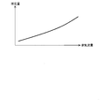
- the amount (adsorption capacity) of NH 3 that can be adsorbed by the SCR catalyst tends to decrease as the temperature of the SCR catalyst increases. Therefore, as shown in FIG. 3, when the temperature of the SCR catalyst becomes equal to or higher than a predetermined temperature (Tsm in FIG. 3) higher than the lower limit temperature (Tsl in FIG. 3), NH that is oxidized per unit time in the SCR catalyst. Compared with the amount of 3 (oxidation rate), the amount of NH 3 (desorption rate) desorbed from the SCR catalyst per unit time increases. Therefore, when the temperature of the SCR catalyst is equal to or higher than the predetermined temperature Tsm higher than the lower limit temperature Tsl, the ECU 7 executes a process for raising the temperature of the SCR catalyst (temperature raising process).
- the adsorption capacity after the temperature of the SCR catalyst is increased by the temperature raising process may be smaller than the NH 3 adsorption amount (current NH 3 adsorption amount) before the temperature raising process is performed.
- the SCR catalyst is desorbed during the temperature raising process.
- the amount of NH 3 may be excessive. If the amount of NH 3 desorbed from the SCR catalyst becomes excessive during the temperature raising process, NH 3 discharged into the atmosphere may generate an irritating odor. Therefore, the temperature increase process is performed so that the amount of NH 3 desorbed from the SCR catalyst during the temperature increase process does not generate an irritating odor (the same amount or less as the above-mentioned allowable amount). Shall be. Specifically, as shown in FIG.
- the ECU 7 subtracts a predetermined amount from the current NH 3 adsorption amount of the SCR catalyst, and the target value of the adsorption capacity of the SCR catalyst after execution of the temperature raising process (FIG. Middle target capacity).
- the “predetermined amount” here is an amount obtained by subtracting a predetermined margin from the allowable amount.
- the predetermined amount may be a fixed value or a variable value that is changed according to the exhaust gas flow rate. For example, the odor of NH 3 when exhaust gas is discharged into the atmosphere becomes stronger as the concentration of NH 3 contained in the exhaust gas becomes higher. Therefore, as shown in FIG. 5, the predetermined amount may be set to a smaller value as the exhaust flow rate decreases.
- the ECU 7 obtains the temperature of the SCR catalyst (Tstrg in FIG. 4) at which the adsorption capacity of the SCR catalyst becomes equal to the target capacity, and sets the temperature Tstrg as the target temperature of the SCR catalyst in the temperature raising process. At that time, as shown in FIG. 4, the correlation between the adsorption capacity of the SCR catalyst and the temperature of the SCR catalyst is experimentally obtained in advance. Next, the ECU 7 calculates the retard amount of the ignition timing and the advance amount of the opening timing of the exhaust valve based on the difference between the current temperature of the SCR catalyst (Tspt in FIG. 4) and the target temperature Tstrg. do it.
- the retard amount of the ignition timing and the advance amount of the exhaust valve opening timing may be fixed values determined in advance.
- the ECU 7 may end the temperature raising process when the temperature of the SCR catalyst reaches the target temperature Tstrg.
- the NH 3 adsorption amount of the SCR catalyst can be reduced without generating an irritating odor.
- the target air-fuel ratio of the air-fuel mixture when the temperature raising process is executed may be set to an air-fuel ratio determined according to the operating state of the internal combustion engine 1, but is set to the predetermined lean air-fuel ratio. May be.
- the target air-fuel ratio of the air-fuel mixture is set to the predetermined lean air-fuel ratio when the temperature raising process is executed, desorption of NH 3 adsorbed on the SCR catalyst is promoted and the SCR catalyst Oxidation of NH 3 adsorbed or NH 3 desorbed from the SCR catalyst is promoted.
- the amount of NH 3 adsorbed by the SCR catalyst can be rapidly reduced while suppressing the amount of NH 3 discharged into the atmosphere below the allowable amount.
- the air-fuel ratio of the air-fuel mixture at the time of executing the temperature raising process is set to the predetermined lean air-fuel ratio, the deterioration of the fuel consumption rate can be suppressed to a minimum.
- the temperature raising process be performed by a method of retarding the ignition timing of the internal combustion engine 1 or a method of advancing the valve opening timing of the exhaust valve of the internal combustion engine 1.
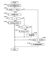
- FIG. 6 is a flowchart showing a processing routine executed by the ECU 7 when the NH 3 adsorption amount of the SCR catalyst is decreased.
- This processing routine is stored in advance in the ROM of the ECU 7, and is periodically executed by the ECU 7.
- the ECU 7 first reads the NH 3 adsorption amount Adnh3 of the SCR catalyst in the processing of S101.
- the NH 3 adsorption amount Adnh3 of the SCR catalyst is obtained by integrating the value obtained by subtracting the NH 3 consumption amount and the NH 3 slip amount from the total amount of NH 3 produced by the three-way catalyst and the NSR catalyst. Desired.
- the ECU 7 determines whether or not the NH 3 adsorption amount Adnh3 read in the process of S101 is equal to or greater than a predetermined threshold value Adthre1.
- a predetermined threshold Adthre1 as described above, when the adsorbed NH 3 amount of the SCR catalyst is the predetermined threshold value Adthre1 above, the internal combustion engine 1 in an easy operating condition NH 3 is desorbed adsorbed on the SCR catalyst
- the amount of NH 3 desorbed from the SCR catalyst and discharged into the atmosphere is an amount obtained by subtracting a predetermined margin from the amount of NH 3 adsorbed that is considered to exceed the allowable amount.
- the ECU 7 reads the temperature Ts of the SCR catalyst in the process of S103. Specifically, the ECU 7 reads the measured value of the temperature sensor 12 as the temperature Ts of the SCR catalyst. In addition, when the temperature sensor is also attached to the exhaust pipe 3 between the second catalyst casing 5 and the third catalyst casing 6, from the difference between the measured value of the temperature sensor and the measured value of the temperature sensor 12. The temperature Ts of the SCR catalyst may be calculated. By obtaining the temperature Ts of the SCR catalyst by these methods, the “detecting means” according to the present invention is realized.
- the ECU 7 determines whether or not the temperature Ts read in the process of S103 is lower than the lower limit temperature Tsl.
- the lower limit temperature Tsl is the lower limit value of the temperature at which NH 3 can be oxidized as described above. If an affirmative determination is made in the process of S104 (Ts ⁇ Tsl), the ECU 7 proceeds to the process of S105.
- the ECU 7 sets the target air-fuel ratio A / Ftrg of the air-fuel mixture to a predetermined weak lean air-fuel ratio A / Fsl.
- the predetermined weak lean air-fuel ratio A / Fsl is an air-fuel ratio at which the amount of NO x flowing out from the three-way catalyst is larger than zero as described in the description of FIG.
- the target air-fuel ratio A / Ftrg of the mixture is set to a predetermined slightly lean air-fuel ratio A / Fsl
- the exhaust gas flowing out of the NSR catalyst is to contain relatively large amounts of NO X.
- the amount of NH 3 contributing to the reduction of NO x in the SCR catalyst increases.
- the NH 3 adsorption amount Adnh3 of the SCR catalyst can be effectively reduced.
- the ECU 7 proceeds to the process of S106, and determines whether or not the temperature Ts read in the process of S103 is less than a predetermined temperature Tsm. To do. That is, the ECU 7 determines whether or not the temperature Ts of the SCR catalyst belongs to a temperature range equal to or higher than the lower limit temperature Tsl and lower than the predetermined temperature Tsm. As described above, the predetermined temperature Tsm is the minimum value of the temperature at which the amount of NH 3 desorbed from the SCR catalyst per unit time is larger than the amount of NH 3 oxidized per unit time in the SCR catalyst. It is. If an affirmative determination is made in the process of S106 (Ts ⁇ Tsm), the ECU 7 proceeds to the process of S107.
- the ECU 7 sets the target air-fuel ratio A / Ftrg of the air-fuel mixture to a predetermined lean air-fuel ratio A / Fl.
- the predetermined lean air-fuel ratio A / Fl is higher than the predetermined weak lean air-fuel ratio A / Fsl, and the combustion stability and drivability of the internal combustion engine 1 can be ensured.
- the highest air-fuel ratio within the air-fuel ratio range (or the highest air-fuel ratio within the range where exhaust emissions other than NH 3 do not exceed the regulation value).
- the predetermined lean air-fuel ratio A / Fl may be an air-fuel ratio determined according to the operating state of the internal combustion engine 1. Good.
- the target air-fuel ratio A / Ftrg of the air-fuel mixture is set to a predetermined lean air-fuel ratio A / Fl
- exhaust gas containing a relatively large amount of oxygen is supplied to the SCR catalyst.
- the NO X is produced by the reaction of NH 3 and oxygen adsorbed on the SCR catalyst, so that the NO X is reacted with NH 3 adsorbed by the SCR catalyst.
- the NH 3 adsorption amount Adnh3 of the SCR catalyst can be effectively reduced.
- the ECU 7 proceeds to the process of S108.
- the ECU 7 executes a temperature raising process. Specifically, the ECU 7 accelerates the temperature increase of the SCR catalyst by executing a process for retarding the ignition timing of the internal combustion engine 1 or a process for advancing the valve opening timing of the exhaust valve of the internal combustion engine 1. .
- the ECU 7 sets the target temperature of the SCR catalyst so that the amount of NH 3 desorbed from the SCR catalyst during the temperature raising process is kept below the predetermined amount. Tstrg is calculated.
- the ECU 7 performs a temperature raising process so that the temperature Ts of the SCR catalyst rises to the target temperature Tstrg.
- the NH 3 adsorption amount of the SCR catalyst can be reduced without generating an irritating odor.
- the ECU 7 may set the target air-fuel ratio of the air-fuel mixture to the predetermined lean air-fuel ratio when executing the temperature raising process.
- the target air-fuel ratio of the air-fuel mixture during the temperature raising process is set to the predetermined lean air-fuel ratio, desorption of NH 3 adsorbed on the SCR catalyst can be promoted and adsorbed on the SCR catalyst.
- the oxidation of NH 3 released from NH 3 and the SCR catalyst can be promoted.
- the ECU 7 finishes executing the process of S108, the ECU 7 once ends the execution of this process routine.
- the ECU 7 proceeds to the process of S109, and determines whether or not the NH 3 adsorption amount Adnh3 of the SCR catalyst read in the process of S101 is equal to or less than a predetermined end determination value Adthre2 that is smaller than the predetermined threshold Adthre1. .
- the ECU 7 If the NH 3 reduction process is being performed when the process of S110 is performed, the ECU 7 returns the target air-fuel ratio A / Ftrg of the air-fuel mixture to the air-fuel ratio corresponding to the operating state of the internal combustion engine 1. The NH 3 reduction process is terminated. If the NH 3 reduction process is not executed when the process of S110 is executed, the ECU 7 continues the non-execution state of the NH 3 reduction process.
- the “control means” according to the present invention is realized. Therefore, the NH 3 adsorption amount of the SCR catalyst can be decreased when the NH 3 adsorption amount of the SCR catalyst becomes equal to or greater than a predetermined threshold value. As a result, since the NH 3 adsorption amount of the SCR catalyst is suppressed from exceeding the predetermined threshold, the amount of NH 3 discharged from the SCR catalyst can be suppressed to the allowable amount or less.
- the air-fuel ratio of the air-fuel mixture is set to a predetermined lean air-fuel ratio higher than a predetermined weak lean air-fuel ratio. Since the amount of NH 3 adsorbed by the SCR catalyst is reduced by setting the fuel ratio, the opportunity for lowering the air-fuel ratio of the air-fuel mixture to a predetermined weak lean air-fuel ratio can be reduced. As a result, the amount of NH 3 discharged from the SCR catalyst can be suppressed to the allowable amount or less while suppressing the deterioration of the fuel consumption rate.
Landscapes
- Engineering & Computer Science (AREA)
- Chemical & Material Sciences (AREA)
- Chemical Kinetics & Catalysis (AREA)
- Combustion & Propulsion (AREA)
- Mechanical Engineering (AREA)
- General Engineering & Computer Science (AREA)
- Health & Medical Sciences (AREA)
- Toxicology (AREA)
- Exhaust Gas After Treatment (AREA)
Abstract
本発明は、NSR触媒とSCR触媒とが排気通路に配置された内燃機関に適用される制御装置において、燃料消費率の悪化を少なく抑えつつ、SCR触媒に吸着されているNH3を減少させることを課題とする。そこで本発明は、NSR触媒とSCR触媒とが排気通路に配置された内燃機関に適用される制御装置であって、SCR触媒に吸着されているNH3を減少させる必要がある場合に、SCR触媒の温度がNH3の酸化可能な下限温度以上であれば、内燃機関で燃焼される混合気の空燃比を理論空燃比より高い所定のリーン空燃比に制御し、SCR触媒の温度が前記下限温度未満であれば、内燃機関で燃焼される混合気の空燃比を前記所定のリーン空燃比より低く、且つ理論空燃比より高い所定の弱リーン空燃比に制御するようにした。
Description
本発明は、選択還元型触媒(SCR(Selective Catalytic Reduction)触媒)が排気通路に配置された内燃機関に適用される制御装置に関する。
三元触媒と吸蔵還元型触媒(NSR(NOX Storage Reduction)触媒)とSCR触媒とが排気通路に配置された内燃機関において、SCR触媒に吸着されているNH3が大気中に排出される可能性がある場合に、内燃機関で燃焼に供される混合気の空燃比を弱リーン空燃比にすることにより、内燃機関から排出されたNOX、及びNSR触媒から脱離したNOXをSCR触媒へ到達させて、SCR触媒に吸着されているNH3を消費させる技術が知られている(例えば、特許文献1を参照)。
また、特許文献2には、SCR触媒とSCR触媒より上流の排気に尿素又はNH3を噴射する噴射ノズルとが排気通路に配置された内燃機関において、SCR触媒の温度が急激に上昇するときに、噴射ノズルからの尿素又はNH3の噴射を停止させるとともに、内燃機関から排出されるNOXの量を増大させることにより、SCR触媒から脱離するNH3をNOXと反応させる技術が開示されている。
ところで、上記した特許文献1に記載の技術によると、SCR触媒に吸着されているNH3が大気中へ排出される可能性がある場合に、混合気の空燃比が内燃機関の運転条件に適したリーン空燃比よりも低い弱リーン空燃比に制御されるため、燃料消費率が悪化する可能性がある。
本発明は、上記した実情に鑑みてなされたものであり、その目的は、NSR触媒とSCR触媒とが排気通路に配置された内燃機関に適用される制御装置において、燃料消費率の悪化を少なく抑えつつ、SCR触媒から排出されるNH3の量を少なく抑えることができる技術の提供にある。
本発明は、上記した課題を解決するために、NSR触媒とSCR触媒とが排気通路に配置された内燃機関に適用される制御装置であって、SCR触媒に吸着されているNH3を減少させる必要がある場合に、SCR触媒の温度がNH3の酸化可能な下限温度以上であれば、内燃機関で燃焼される混合気の空燃比を理論空燃比より高い所定のリーン空燃比に制御し、SCR触媒の温度が前記下限温度未満であれば、内燃機関で燃焼される混合気の空燃比を前記所定のリーン空燃比より低く、且つ理論空燃比より高い所定の弱リーン空燃比に制御するようにした。
詳細には、本発明は、排気通路に配置され、NSR触媒を具備する第一排気浄化装置と、前記第一排気浄化装置より下流の排気通路に配置され、SCR触媒を具備する第二排気浄化装置と、を備える内燃機関に適用される制御装置であって、該制御装置は、前記SCR触媒に吸着されているNH3の量であるNH3吸着量を取得する取得手段と、前記SCR触媒の温度を検出する検出手段と、前記取得手段により取得されるNH3吸着量が所定の閾値以上であるときに、前記検出手段により検出される温度がNH3の酸化可能な下限温度以上であれば、内燃機関で燃焼される混合気の空燃比を理論空燃比より高い所定のリーン空燃比に制御し、前記検出手段により検出される温度が前記下限温度未満であれば、内燃機関で燃焼される混合気の空燃比を前記所定のリーン空燃比より低く、且つ単位時間あたりにNSR触媒に吸蔵されるNOXの量に比して単位時間あたりにNSR触媒から流出するNOXの量が多くなる所定の弱リーン空燃比に制御する制御手段と、を備えるようにした。ここでいう「所定の閾値」は、SCR触媒のNH3吸着量が該所定の閾値以上であるときに、SCR触媒に吸着されているNH3が脱離し易い運転条件で内燃機関が運転されると、SCR触媒から脱離して大気中へ排出されるNH3の量が許容量(例えば、刺激性のある臭気を生じさせない量の最大値)を超えると考えられるNH3吸着量、又は該NH3吸着量から所定のマージンを差し引いた量であり、予め実験等を利用して適合作業によって求めておくものとする。
このような構成によれば、取得手段により取得されたNH3吸着量が前記所定の閾値以上になったときに、検出手段により検出される温度が前記下限温度未満であれば、混合気の空燃比が所定の弱リーン空燃比に制御される。その際の所定の弱リーン空燃比は、前記所定のリーン空燃比より低く、且つ単位時間あたりにNSR触媒に吸蔵されるNOXの量に比して単位時間あたりにNSR触媒から流出するNOXの量が多くなる空燃比である。SCR触媒の温度が前記下限温度未満であるときに混合気の空燃比が前記所定の弱リーン空燃比に制御されると、比較的多量のNOXがNSR触媒から流出する。その結果、SCR触媒に吸着されていたNH3は、NSR触媒から流出するNOXと反応して消費される。
一方、取得手段により取得されたNH3吸着量が前記所定の閾値以上になったときに、検出手段により検出される温度が前記下限温度以上であれば、混合気の空燃比が所定のリーン空燃比に制御される。その際の所定のリーン空燃比は、内燃機関の燃焼安定性やドライバビリティを確保することができる空燃比の範囲内で最も高い空燃比であってもよく、又はNH3以外の排気エミッションが規制値を超えない範囲内で最も高い空燃比であってもよい。なお、取得手段により取得されたNH3吸着量が前記所定の閾値以上となったときの内燃機関の運転状態がリーン運転領域(混合気の空燃比がリーン空燃比に設定される運転領域)に属している場合は、前記所定のリーン空燃比は、内燃機関の運転状態に応じて決定される空燃比と同等にされてもよい。混合気の空燃比が前記所定のリーン空燃比に制御されると、比較的多量の酸素を含む排気がSCR触媒へ供給されることになる。SCR触媒の温度が前記下限温度以上であるときに、比較的多量の酸素を含む排気がSCR触媒へ供給されると、該SCR触媒に吸着されていたNH3が排気中の酸素と反応してNOXに転化されるとともに、NH3から転化したNOXがSCR触媒に吸着されているNH3と反応して還元される。
したがって、本発明の内燃機関の制御装置によれば、SCR触媒のNH3吸着量が所定の閾値以上となったときに、該SCR触媒に吸着されているNH3の量を減少させることができる。その結果、SCR触媒のNH3吸着量が前記所定の閾値を超過することが抑制されるため、前述の許容量より多いNH3がSCR触媒から排出されることも抑制される。また、本発明の内燃機関の制御装置は、NH3吸着量が前記所定の閾値以上になったときに、SCR触媒の温度が前記下限温度以上であれば、混合気の空燃比を前記所定の弱リーン空燃比より高い所定のリーン空燃比に制御することで、SCR触媒のNH3吸着量を減少させるため、前述の従来技術に比べ、混合気の空燃比を所定の弱リーン空燃比まで低下させる機会を少なく抑えることができる。その結果、燃料消費率の悪化を少なく抑えつつ、SCR触媒から排出されるNH3の量を少なく抑えることができる。
ここで、前記制御手段は、前記取得手段により取得されるNH3吸着量が所定の閾値以上であるときに、前記検出手段により検出される温度が前記下限温度より高い所定温度以上であれば、前記選択還元型触媒を昇温させるための昇温処理を実行してもよい。
SCR触媒は、該SCR触媒の温度がある程度高くなると、該SCR触媒の温度が高くなるほど該SCR触媒の吸着可能なNH3の量が少なくなる特性を有する。そのため、SCR触媒の温度が前記下限温度より高い所定温度以上になると、SCR触媒において単位時間あたりに酸化されるNH3の量に比して、単位時間あたりにSCR触媒から脱離するNH3の量が多くなる。そこで、SCR触媒のNH3吸着量が前記所定の閾値以上であるときに、SCR触媒の温度が前記所定温度以上であれば、SCR触媒を昇温させることにより、SCR触媒から積極的にNH3を脱離させるようにしてもよい。その際、昇温処理によるSCR触媒の温度上昇量が過剰に多くなると、昇温処理の実行中にSCR触媒から脱離するNH3の量が過剰に多くなる可能性がある。昇温処理の実行中にSCR触媒から脱離するNH3の量が過剰に多くなると、大気中に排出されるNH3が刺激性のある臭気を発生させる可能性がある。そのため、昇温処理は、該昇温処理の実行中にSCR触媒から脱離するNH3の量が刺激性のある臭気を発生させない量に収まるように行われるものとする。
なお、SCR触媒を昇温させる方法として、燃料噴射量を増量させる方法や、排気中へ燃料を添加する方法が用いられると、内燃機関の燃料消費率が悪化する可能性がある。そのため、前記昇温処理は、内燃機関の点火時期を遅角させる方法、又は内燃機関の排気弁の開弁時期を進角させる方法によって行われてもよい。その場合、燃料消費率の悪化を少なく抑えつつ、SCR触媒のNH3吸着量を減少させることができる。また、昇温処理が実行される際の混合気の空燃比は、内燃機関の運転状態に応じて決定される空燃比と同等に設定されてもよいが、前記所定のリーン空燃比と同等に設定されもよい。昇温処理が実行される際に、混合気の空燃比が前記所定のリーン空燃比に設定されると、燃料消費率の悪化を少なく抑えつつ、SCR触媒のNH3吸着量を減少させることができる。
ここで、前述した内燃機関の制御装置は、第一排気浄化装置がNSR触媒と三元触媒とを具備する場合にも有効である。第一排気浄化装置がNSR触媒と三元触媒とを具備する構成においては、混合気の空燃比が理論空燃比、又は理論空燃比より低いリッチ空燃比に制御されたときに、NSR触媒に加え、三元触媒においてもNH3が生成される。そのため、第一排気浄化装置がNSR触媒と三元触媒とを具備する場合は、第一排気浄化装置がNSR触媒のみを具備する場合に比べ、SCR触媒のNH3吸着量が前記所定の閾値以上となる機会が多くなる。よって、本発明に係わる内燃機関の制御装置を、第一排気浄化装置がNSR触媒と三元触媒とを具備する構成に適用すると、SCR触媒のNH3吸着量を減少させる際の燃料消費率の悪化をより効果的に少なく抑えることができる。
本発明によれば、燃料消費率の悪化を少なく抑えつつ、SCR触媒から排出されるNH3の量を少なく抑えることができる。
以下、本発明の具体的な実施形態について図面に基づいて説明する。本実施形態に記載される構成部品の寸法、材質、形状、相対配置等は、特に記載がない限り発明の技術的範囲をそれらのみに限定する趣旨のものではない。
図1は、本発明を適用する内燃機関とその排気系の概略構成を示す図である。図1に示す内燃機関1は、理論空燃比より高い空燃比(リーン空燃比)の混合気により運転可能な火花点火式の内燃機関(ガソリンエンジン)である。
内燃機関1は、燃料噴射弁2を備えている。燃料噴射弁2は、吸気通路(例えば、吸気ポート)へ燃料を噴射する弁装置であってもよく、又は気筒内へ燃料を噴射する弁装置であってもよい。内燃機関1は、排気管3と接続されている。排気管3は、内燃機関1の気筒内で燃焼されたガス(排気)が流通させる管である。排気管3の途中には、第一触媒ケーシング4が配置されている。第一触媒ケーシング4は、アルミナ等のコート層によって被覆されたハニカム構造体と、前記コート層に担持される貴金属(例えば、白金、パラジウム、又はロジウム等)とから構成される三元触媒を収容する。
第一触媒ケーシング4より下流の排気管3には、第二触媒ケーシング5が配置される。第二触媒ケーシング5は、アルミナ等のコート層によって被覆されたハニカム構造体と、コート層に担持される貴金属(白金、パラジウム、ロジウム等)と、コート層に担持されるNOX吸蔵剤(アルカリ類、アルカリ土類等)とから構成される吸蔵還元型触媒(NSR触媒)を収容する。
第二触媒ケーシング5より下流の排気管3には、第三触媒ケーシング6が配置される。第三触媒ケーシング6は、コーディライトやFe-Cr-Al系の耐熱鋼から成るハニカム構造体と、ハニカム構造体を被覆するゼオライト系のコート層と、コート層に担持される貴金属(白金やパラジウム等)とから構成される選択還元型触媒(SCR触媒)を収容する。
ここで、前記第一触媒ケーシング4と前記第二触媒ケーシング5との組合せは、本発明に係わる「第一排気浄化装置」に相当する。また、前記第三触媒ケーシング6は、本発明に係わる「第二排気浄化装置」に相当する。
このように構成された内燃機関1には、ECU7が併設される。ECU7は、CPU、ROM、RAM、バックアップRAM等から構成される電子制御ユニットである。ECU7は、空燃比センサ(A/Fセンサ)8、酸素濃度センサ(O2センサ)9、第一NOXセンサ10、第二NOXセンサ11、温度センサ12、アクセルポジションセンサ13、クランクポジションセンサ14、及びエアフローメータ15等の各種センサと電気的に接続されている。
空燃比センサ8は、第一触媒ケーシング4より上流の排気管3に取り付けられ、第一触媒ケーシング4へ流入する排気の空燃比に相関する電気信号を出力する。酸素濃度センサ9は、第一触媒ケーシング4と第二触媒ケーシング5との間の排気管3に取り付けられ、第一触媒ケーシング4から流出した排気に含まれる酸素の濃度に相関する電気信号を出力する。第一NOXセンサ10は、第二触媒ケーシング5と第三触媒ケーシング6との間の排気管3に取り付けられ、第二触媒ケーシング5から流出する排気(言い換えると、第三触媒ケーシング6へ流入する排気)に含まれるNOXの濃度に相関する電気信号を出力する。第二NOXセンサ11は、第三触媒ケーシング6より下流の排気管3に取り付けられ、第三触媒ケーシング6から流出する排気に含まれるNOXの濃度に相関する電気信号を出力する。アクセルポジションセンサ13は、アクセルペダルの操作量(アクセル開度)に相関する電気信号を出力する。クランクポジションセンサ14は、内燃機関1の出力軸(クランクシャフト)の回転位置に相関する電気信号を出力する。エアフローメータ15は、内燃機関1の気筒内に吸入される空気量(吸入空気量)に相関する電気信号を出力する。
ECU7は、上記した各種センサの出力信号に基づいて、内燃機関1の運転状態を制御する。例えば、ECU7は、クランクポジションセンサ14の出力信号に基づいて演算される機関回転速度とアクセルポジションセンサ13の出力信号(アクセル開度)とに基づいて混合気の目標空燃比を演算する。ECU7は、目標空燃比とエアフローメータ15の出力信号(吸入空気量)に基づいて燃料噴射弁2の目標燃料噴射量(燃料噴射期間)を演算し、目標燃料噴射量に従って燃料噴射弁2を作動させる。
なお、ECU7は、内燃機関1の運転状態が低回転・低負荷領域又は中回転・中負荷領域(以下、「リーン運転領域」と称する)に属するときは、目標空燃比を理論空燃比より高いリーン空燃比に設定する。ECU7は、内燃機関1の運転状態が高負荷領域又は高回転領域(以下、「リッチ運転領域」と称する)は、目標空燃比を理論空燃比又は理論空燃比より低いリッチ空燃比に設定する。このように、内燃機関1の運転状態がリーン運転領域に属するときに、目標空燃比がリーン空燃比に設定されると、燃料消費量を少なく抑えることができる。また、ECU7は、空燃比センサ8の出力信号が前記目標空燃比と一致するように目標燃料噴射量を補正する空燃比フィードバック制御や、酸素濃度センサ9の出力信号に基づいて空燃比フィードバック制御に使用される補正係数の学習制御等を行う。
ところで、目標空燃比がリーン空燃比に設定される場合は、第一触媒ケーシング4に収容された三元触媒のNOX浄化性能が低くなる。そのため、目標空燃比がリーン空燃比に設定されている場合は、第二触媒ケーシング5のNSR触媒と第三触媒ケーシング6のSCR触媒によって排気中のNOXを浄化する必要がある。
前記NSR触媒は、第二触媒ケーシング5へ流入する排気の酸素濃度が高いとき(排気の空燃比がリーンであるとき)は、排気中のNOXを吸蔵又は吸着する。NSR触媒は、第二触媒ケーシング5へ流入する排気の酸素濃度が低く、且つ炭化水素(HC)や一酸化炭素(CO)等の還元成分が排気に含まれるとき(排気の空燃比がリッチであるとき)は、該NSR触媒に吸蔵されていたNOXを放出し、放出されたNOXを窒素(N2)に還元させる。
そこで、ECU7は、前記リーン運転領域においては、NSR触媒のNOX吸蔵量が一定量以上になったときに、リッチスパイク処理を実行する。リッチスパイク処理は、排気中の酸素濃度が低く且つHCやCOの濃度が高くなるように、燃料噴射量や吸入空気量を調整する処理である。より具体的には、リッチスパイク処理は、燃料噴射弁2の燃料噴射量を増加させる処理、又は吸気絞り弁(スロットル弁)の開度を減少させる処理の少なくなくとも一つを実行する処理である。なお、燃料噴射弁2が気筒内に直接燃料を噴射するように配置される場合は、気筒の排気行程中に燃料噴射弁2から燃料を噴射させる方法によりリッチスパイク処理が実行されてもよい。また、リッチスパイク処理は、前回のリッチスパイク処理終了時からの運転時間(好ましくは、目標空燃比がリーン空燃比に設定された運転時間)が一定時間以上になったときに実行されてもよく、又は前回のリッチスパイク処理終了時からの走行距離(好ましくは、目標空燃比がリーン空燃比に設定された走行距離)が一定距離以上になったときに実行されてもよい。
前記SCR触媒は、排気中に含まれるアンモニア(NH3)を吸着する。SCR触媒は、該SCR触媒に吸着されたNH3と排気中のNOXを反応させることにより、NOXを窒素(N2)に還元させる。なお、SCR触媒へ供給されるNH3は、三元触媒やNSR触媒において生成される。例えば、リッチスパイク処理が実行された場合に、三元触媒においてNOXの一部がNH3に還元され、NSR触媒において該NSR触媒から流出したNOXの一部がNH3に還元される。その際、NSR触媒において生成されるNH3の量は、リッチスパイク処理が実行される間隔や、リッチスパイク処理が実行されるときの空燃比等によって変化する。よって、SCR触媒へNH3を供給する場合は、リッチスパイク処理の実行間隔がNH3の生成に適した間隔に設定され、又はリッチスパイク処理実行時の空燃比がNH3の生成に適した空燃比(例えば、14.1程度)に設定されればよい。
ところで、内燃機関1の運転状態が前記リッチ運転領域に属するときは、混合気の目標空燃比が理論空燃比又はリッチ空燃比に設定されるため、排気中に含まれるNOXが第一触媒ケーシング4の三元触媒で浄化される。よって、第三触媒ケーシング6のSCR触媒へ到達するNOXの量が零又は極めて少なくなるため、SCR触媒に吸着されているNH3がほとんど消費されないことになる。また、混合気の目標空燃比が理論空燃比又はリッチ空燃比に設定されるときは、第一触媒ケーシング4の三元触媒、及び第二触媒ケーシング5のNSR触媒によってNH3が生成されるため、第三触媒ケーシング6のSCR触媒に吸着されるNH3の量が増加する。よって、内燃機関1の運転状態が前記リッチ運転領域に属する機会が多くなると、SCR触媒のNH3吸着能力が飽和する可能性がある。SCR触媒のNH3吸着能力が飽和すると、比較的多量のNH3が大気中に排出されて、臭気を発生させる可能性がある。
そこで、本実施形態においては、SCR触媒のNH3吸着量が所定の閾値以上になると、SCR触媒のNH3吸着量を減少させる処理(以下、「NH3低減処理」と称する)を実行するようにした。なお、ここでいう「所定の閾値」は、SCR触媒のNH3吸着量が該所定の閾値以上であるときに、SCR触媒に吸着されているNH3が脱離し易い運転条件で内燃機関1が運転されると、SCR触媒から脱離して大気中へ排出されるNH3の量が許容量(例えば、刺激性のある臭気を生じさせない量の最大値)を超えると考えられるNH3吸着量から所定のマージンを差し引いた量であり、予め実験等を利用して適合作業によって求めておくものとする。なお、ここでいう「SCR触媒に吸着されているNH3が脱離し易い運転条件」とは、例えば、加速運転のように、排気の流量が急速に多くなり易く、且つ排気の温度が急速に高くなり易い運転条件である。
以下、本実施形態におけるNH3低減処理の実行方法について述べる。先ず、ECU7は、NH3低減処理を実行するにあたり、SCR触媒のNH3吸着量を取得する。SCR触媒のNH3吸着量は、第三触媒ケーシング6のSCR触媒へ供給されるNH3の量から、NH3消費量(NOXの還元に寄与するNH3の量)及びNH3スリップ量(SCR触媒をすり抜けるNH3の量)を減算した値を積算することによって求められる。
ここで、SCR触媒へ供給されるNH3の量は、第一触媒ケーシング4の三元触媒で生成されるNH3の量と第二触媒ケーシング5のNSR触媒で生成されるNH3の量との総量である。三元触媒で生成されるNH3の量は、排気の空燃比と排気流量と三元触媒の温度とに相関する。そのため、それらの相関を予め求めておけば、排気の空燃比と排気流量と三元触媒の温度とを引数として、三元触媒で生成されるNH3の量を求めることができる。一方、NSR触媒で生成されるNH3の量は、排気の空燃比と排気流量とNSR触媒の温度とに相関する。そのため、それらの相関を予め求めておけば、排気の空燃比と排気流量とNSR触媒の温度とを引数として、NSR触媒で生成されるNH3の量を求めることができる。
前記NH3消費量は、前記SCR触媒へ流入するNOXの量(NOX流入量)とSCR触媒のNOX浄化率とをパラメータとして演算される。その際、NOX流入量は、第一NOXセンサ10の測定値(第三触媒ケーシング6へ流入する排気のNOX濃度)と排気流量(エアフローメータ15の測定値と燃料噴射量との総量)を乗算することにより演算される。一方、SCR触媒のNOX浄化率は、排気流量とSCR触媒の温度とをパラメータとして演算される。なお、SCR触媒のNOX浄化率と排気流量とSCR触媒の温度との相関は、予め実験的に求めておくものとする。
前記NH3スリップ量は、NH3吸着量の前回の演算値と、SCR触媒の温度と、排気の流量と、をパラメータとして求められる。ここで、排気の流量が一定であれば、NH3吸着量が多くなるほど、およびまたはSCR触媒の温度が高くなるほど、SCR触媒から流出する排気のNH3濃度が高くなる。また、SCR触媒から流出する排気のNH3濃度が一定であれば、排気の流量が多くなるほど、単位時間あたりのNH3スリップ量が多くなる。これらの相関を踏まえると、NH3吸着量の前回の演算値とSCR触媒の温度とをパラメータとしてSCR触媒から流出する排気のNH3濃度を求め、次いでそのNH3濃度に排気の流量を乗算することで、NH3スリップ量を求めることができる。
上記した方法によって求められるNH3吸着量が前記所定の閾値以上に達すると、ECU7は、NH3低減処理を実行する。先ず、ECU7は、SCR触媒の温度がNH3の酸化可能な下限温度未満であれば、混合気の目標空燃比を理論空燃比より高い所定の弱リーン空燃比に設定する。ここでいう「弱リーン空燃比」は、単位時間あたりに三元触媒へ流入するNOXの量に比して、単位時間あたりに三元触媒で浄化されるNOXの量が少なくなる(三元触媒から流出するNOXの量が零より大きくなる空燃比)であって、且つ単位時間あたりにNSR触媒に吸蔵されるNOXの量に比して、単位時間あたりにNSR触媒から流出するNOXの量が多くなる空燃比である。好ましくは、所定の弱リーン空燃比は、図2に示すように、単位時間あたりに三元触媒へ流入するNOXの量に比して単位時間あたりに三元触媒で浄化されるNOXの量が少なくなる空燃比であって、且つ単位時間あたりにNSR触媒に吸蔵されるNOXの量に比して単位時間あたりにNSR触媒から流出するNOXの量が多くなる空燃比の範囲(図2中のA/F1~A/F2の範囲)において、NSR触媒から流出するNOXの量が最大となる空燃比(図2中のA/Fmax)である。このような空燃比A/Fmaxが所定の弱リーン空燃比に定められると、NSR触媒のNOX吸蔵量が比較的少ない状態でNH3低減処理が実行される場合であっても、比較的多量のNOXを第三触媒ケーシング6のSCR触媒へ供給することができる。SCR触媒の温度が前記下限温度未満であるときに、比較的多量のNOXがSCR触媒へ供給されると、SCR触媒においてNOXの還元に消費されるNH3の量が多くなる。その結果、SCR触媒のNH3吸着量を効果的に減少させることができる。ところで、第三触媒ケーシング6より上流に第二触媒ケーシング5のみが配置される場合は、前記所定の弱リーン空燃比は、単位時間あたりにNSR触媒に吸蔵されるNOXの量に比して、単位時間あたりにNSR触媒から流出するNOXの量が多くなる空燃比の範囲において、NSR触媒から流出するNOXの量が最大となる空燃比に設定されればよい。また、第三触媒ケーシング6より上流に第一触媒ケーシング4のみが配置される場合は、前記所定の弱リーン空燃比は、単位時間あたりに三元触媒へ流入するNOXの量に比して、単位時間あたりに三元触媒で浄化されるNOXの量が少なくなる空燃比の範囲において、三元触媒から流出するNOXの量が最大となる空燃比に設定されればよい。
次に、NH3吸着量が前記所定の閾値以上であるときに、SCR触媒の温度が前記下限温度以上であれば、ECU7は、混合気の目標空燃比を前記所定の弱リーン空燃比より高い所定のリーン空燃比に設定する。ここでいう「所定のリーン空燃比」は、内燃機関1の燃焼安定性やドライバビリティを確保することができる空燃比の範囲内で最も高い空燃比であってもよく、又はNH3以外の排気エミッションが規制値を超えない範囲内で最も高い空燃比であってもよい。なお、NH3低減処理を実行する際の内燃機関1の運転状態が前記リーン運転領域に属している場合は、前記所定のリーン空燃比は、内燃機関1の運転状態に応じて決定される空燃比と同等に設定されてもよい。混合気の目標空燃比が前記所定のリーン空燃比に設定される場合は、酸素濃度の高い排気がSCR触媒へ流入することになる。SCR触媒の温度が前記下限温度以上であるときに、酸素濃度の高い排気がSCR触媒へ供給されると、SCR触媒に吸着されているNH3の酸化が促進される。ここで、SCR触媒に吸着されているNH3が酸化されると、NOXが生成される。このようにして生成されたNOXは、SCR触媒に吸着されているNH3と反応して還元される。よって、SCR触媒の温度が前記下限温度以上であるときに、混合気の空燃比を前記所定のリーン空燃比に設定することで、SCR触媒に吸着されているNH3の酸化を促進させると、SCR触媒のNH3吸着量を効果的に減少させることができる。
ところで、SCR触媒が吸着可能なNH3の量(吸着容量)は、該SCR触媒の温度が高くなるほど少なくなる傾向がある。そのため、図3に示すように、SCR触媒の温度が前記下限温度(図3中のTsl)より高い所定温度(図3中のTsm)以上になると、SCR触媒において単位時間あたりに酸化されるNH3の量(酸化速度)に比して、単位時間あたりにSCR触媒から脱離するNH3の量(脱離速度)が多くなる。そこで、ECU7は、SCR触媒の温度が前記下限温度Tslより高い所定温度Tsm以上であるときは、SCR触媒の温度を昇温させる処理(昇温処理)を実行するものとする。
SCR触媒の温度が前記所定温度Tsm以上であるときに前記昇温処理が実行されると、単位時間あたりにSCR触媒から脱離するNH3の量が増加するため、SCR触媒のNH3吸着量を減少させることができる。ところで、前記昇温処理によってSCR触媒の温度が高められると、それに伴ってSCR触媒の吸着容量が減少する。そのため、前記昇温処理によりSCR触媒の温度が高められた後における吸着容量は、前記昇温処理の実行前のNH3吸着量(現在のNH3吸着量)より少なくなる可能性がある。その際、前記昇温処理によりSCR触媒の温度が高められた後における吸着容量と現在のNH3吸着量との差が過剰に大きくなると、前記昇温処理の実行中にSCR触媒から脱離するNH3の量が過剰に多くなる可能性がある。そして、前記昇温処理の実行中にSCR触媒から脱離するNH3の量が過剰に多くなると、大気中に排出されたNH3が刺激性のある臭気を発生させる可能性がある。そのため、昇温処理は、該昇温処理の実行中にSCR触媒から脱離するNH3の量が刺激性のある臭気を発生させない量(前述の許容量と同量以下)に収まるように行われるものとする。具体的には、ECU7は、図4に示すように、SCR触媒の現在のNH3吸着量から所定量を減算して、昇温処理の実行後におけるSCR触媒の吸着容量の目標値(図4中の目標容量)を演算する。ここでいう「所定量」は、前記許容量から所定のマージンを差し引いた量である。なお、所定量は、固定値であってもよいが、排気流量に応じて変更される可変値であってもよい。例えば、排気が大気中へ排出された際のNH3の臭いは、排気中に含まれるNH3の濃度が高くなるほど強くなる。そのため、前記所定量は、図5に示すように、排気流量が少なくなるほど小さい値に設定されてもよい。次に、ECU7は、SCR触媒の吸着容量が前記目標容量と等しくなるSCR触媒の温度(図4中のTstrg)を求め、その温度Tstrgを昇温処理におけるSCR触媒の目標温度に設定する。その際、図4に示すような、SCR触媒の吸着容量とSCR触媒の温度との相関を予め実験的に求めておくものとする。次に、ECU7は、SCR触媒の現在の温度(図4中のTspt)と前記目標温度Tstrgとの差に基づいて、点火時期の遅角量や排気弁の開弁時期の進角量を演算すればよい。なお、点火時期の遅角量や排気弁の開弁時期の進角量は、予め決定されている固定値としてもよい。その場合は、ECU7は、SCR触媒の温度が目標温度Tstrgに達した時点で昇温処理を終了すればよい。このような方法によって昇温処理が実行されると、刺激性のある臭気を発生させることなく、SCR触媒のNH3吸着量を減少させることができる。
なお、昇温処理が実行される際の混合気の目標空燃比は、内燃機関1の運転状態に応じて決定される空燃比に設定されてもよいが、前記所定のリーン空燃比に設定されてもよい。昇温処理が実行される際に、混合気の目標空燃比が前記所定のリーン空燃比に設定されると、SCR触媒に吸着されているNH3の脱離が促進されるとともに、SCR触媒に吸着されているNH3、又はSCR触媒から脱離したNH3の酸化が促進される。その結果、大気中へ排出されるNH3の量を前記許容量以下に抑えつつ、SCR触媒のNH3吸着量を速やかに減少させることができる。また、昇温処理の実行時における混合気の空燃比が前記所定のリーン空燃比に設定されると、燃料消費率の悪化を少なく抑えることもできる。
ところで、SCR触媒を昇温させる方法として、燃料噴射量を増量させる方法や、排気中へ燃料を添加する方法が用いられると、内燃機関1の燃料消費率が悪化する可能性がある。そのため、前記昇温処理は、内燃機関1の点火時期を遅角させる方法、又は内燃機関1の排気弁の開弁時期を進角させる方法によって行われることが望ましい。このような方法によって昇温処理が行われると、昇温処理の実行に伴う燃料消費率の悪化を少なく抑えることができる。
ここで、本実施形態におけるNH3低減処理の実行手順について図6に沿って説明する。図6は、SCR触媒のNH3吸着量を減少させる際にECU7が実行する処理ルーチンを示すフローチャートである。この処理ルーチンは、予めECU7のROMに記憶されており、ECU7によって周期的に実行される。
図6の処理ルーチンでは、ECU7は、先ずS101の処理において、SCR触媒のNH3吸着量Adnh3を読み込む。SCR触媒のNH3吸着量Adnh3は、前述したように、三元触媒及びNSR触媒で生成されるNH3の総量から前記NH3消費量及び前記NH3スリップ量を減算した値を積算することによって求められる。このような方法によってSCR触媒のNH3吸着量を求めることにより、本発明に係わる「取得手段」が実現される。
S102の処理では、ECU7は、前記S101の処理で読み込まれたNH3吸着量Adnh3が所定の閾値Adthre1以上であるか否かを判別する。所定の閾値Adthre1は、前述したように、SCR触媒のNH3吸着量が該所定の閾値Adthre1以上であるときに、SCR触媒に吸着されているNH3が脱離し易い運転条件で内燃機関1が運転されると、SCR触媒から脱離して大気中へ排出されるNH3の量が許容量を超えると考えられるNH3吸着量から所定のマージンを差し引いた量である。S102の処理において肯定判定された場合(Adnh3≧Adnh3thre)は、SCR触媒に吸着されているNH3が脱離し易い運転条件で内燃機関1が運転されると、SCR触媒から許容量以上のNH3が脱離する可能性があるとみなすことができるため、ECU7は、S103以降の処理においてNH3低減処理を実行する。
先ず、ECU7は、S103の処理においてSCR触媒の温度Tsを読み込む。具体的には、ECU7は、温度センサ12の測定値をSCR触媒の温度Tsとして読み込む。なお、第二触媒ケーシング5と第三触媒ケーシング6との間の排気管3にも温度センサが取り付けられている場合は、その温度センサの測定値と前記温度センサ12の測定値との差からSCR触媒の温度Tsを演算してもよい。これらの方法によってSCR触媒の温度Tsを求めることにより、本発明に係わる「検出手段」が実現される。
S104の処理では、ECU7は、前記S103の処理で読み込まれた温度Tsが下限温度Tsl未満であるか否かを判別する。下限温度Tslは、前述したように、NH3が酸化可能な温度の下限値である。S104の処理において肯定判定された場合(Ts<Tsl)は、ECU7は、S105の処理へ進む。
S105の処理では、ECU7は、混合気の目標空燃比A/Ftrgを所定の弱リーン空燃比A/Fslに設定する。所定の弱リーン空燃比A/Fslは、前述の図2の説明で述べたように、三元触媒から流出するNOXの量が零より大きくなる空燃比であって、且つ単位時間あたりにNSR触媒に吸蔵されるNOXの量に比して単位時間あたりにNSR触媒から流出するNOXの量が多くなる空燃比の範囲において、NSR触媒から流出するNOXの量が最大となる空燃比(図2中のA/Fmax)である。このように混合気の目標空燃比A/Ftrgが所定の弱リーン空燃比A/Fslに設定されると、NSR触媒から流出する排気が比較的多量のNOXを含むことになる。比較的多量のNOXを含む排気がSCR触媒へ流入すると、SCR触媒においてNOXの還元に寄与するNH3の量が増加する。その結果、SCR触媒のNH3吸着量Adnh3を効果的に減少させることができる。ECU7は、S105の処理を実行し終えると、本処理ルーチンの実行を一旦終了する。
また、前記S104の処理において否定判定された場合(Ts≧Tsl)は、ECU7は、S106の処理へ進み、前記S103の処理で読み込まれた温度Tsが所定温度Tsm未満であるか否かを判別する。すなわち、ECU7は、SCR触媒の温度Tsが前記下限温度Tsl以上、且つ所定温度Tsm未満の温度範囲に属しているか否かを判別する。所定温度Tsmは、前述したように、SCR触媒において単位時間あたりに酸化されるNH3の量に比して、単位時間あたりにSCR触媒から脱離するNH3の量が多くなる温度の最小値である。S106の処理において肯定判定された場合(Ts<Tsm)は、ECU7は、S107の処理へ進む。
S107の処理では、ECU7は、混合気の目標空燃比A/Ftrgを所定のリーン空燃比A/Flに設定する。所定のリーン空燃比A/Flは、前述したように、前記所定の弱リーン空燃比A/Fslより高い空燃比であって、且つ内燃機関1の燃焼安定性やドライバビリティを確保することができる空燃比の範囲内で最も高い空燃比(又は、NH3以外の排気エミッションが規制値を超えない範囲内で最も高い空燃比)である。なお、現時点における内燃機関1の運転状態が前記リーン運転領域に属している場合は、所定のリーン空燃比A/Flは、内燃機関1の運転状態に応じて決定される空燃比であってもよい。このように混合気の目標空燃比A/Ftrgが所定のリーン空燃比A/Flに設定されると、比較的多量の酸素を含んだ排気がSCR触媒へ供給されることになる。その場合、SCR触媒に吸着されているNH3と酸素とが反応してNOXが生成されるとともに、そのNOXがSCR触媒に吸着されているNH3と反応することになる。その結果、SCR触媒のNH3吸着量Adnh3を効果的に減少させることができる。ECU7は、前記S107の処理を実行し終えると、本処理ルーチンの実行を一旦終了する。
また、前記S106の処理において否定判定された場合(Ts≧Tsm)は、ECU7は、S108の処理へ進む。S108の処理では、ECU7は、昇温処理を実行する。具体的には、ECU7は、内燃機関1の点火時期を遅角させる処理、又は内燃機関1の排気弁の開弁時期を進角させる処理を実行することにより、SCR触媒の昇温を促進させる。その際、ECU7は、前述の図4の説明で述べたように、昇温処理の実行中にSCR触媒から脱離するNH3の量が前記所定量以下に収まるように、SCR触媒の目標温度Tstrgを演算する。そして、ECU7は、SCR触媒の温度Tsが前記目標温度Tstrgまで上昇するように昇温処理を実行する。このように昇温処理が実行されると、刺激性のある臭気を発生させることなく、SCR触媒のNH3吸着量を減少させることができる。なお、ECU7は、昇温処理を実行する際に、混合気の目標空燃比を前記所定のリーン空燃比に設定してもよい。昇温処理の実行時における混合気の目標空燃比が前記所定のリーン空燃比に設定されると、SCR触媒に吸着されているNH3の脱離を促進させることができるとともに、SCR触媒に吸着されているNH3及びSCR触媒から脱離したNH3の酸化を促進させることもできる。よって、昇温処理の実行後において、SCR触媒に吸着されているNH3が脱離し易い運転条件で内燃機関1が運転されても、大気中に排出されるNH3の量をより確実に許容量以下に抑えることができる。さらに、燃料消費率の悪化を少なく抑えることもできる。ECU7は、前記S108の処理を実行し終えると、本処理ルーチンの実行を一旦終了する。
また、前記S102の処理において否定判定された場合(Adnh3<Adnh3thre)は、SCR触媒に吸着されているNH3が脱離し易い運転条件で内燃機関1が運転されても、SCR触媒から許容量以上のNH3が脱離しないとみなすことができる。そのため、ECU7は、S109の処理へ進み、前記S101の処理で読み込まれたSCR触媒のNH3吸着量Adnh3が前記所定の閾値Adthre1より少ない所定の終了判定値Adthre2以下であるか否かを判別する。S109の処理において否定判定された場合(Adnh3>Adthre2)は、ECU7は、本処理ルーチンの実行を一旦終了する。その際、NH3低減処理が実行中であれば、そのNH3低減処理が引き続き実行される。一方、S109の処理において肯定判定された場合(Adnh3≦Adthre2)は、ECU7は、S110の処理へ進む。
S110の処理が実行される際に、NH3低減処理が実行中であれば、ECU7は、混合気の目標空燃比A/Ftrgを内燃機関1の運転状態に応じた空燃比に復帰させることにより、NH3低減処理を終了する。また、S110の処理が実行される際に、NH3低減処理が実行されていなければ、ECU7は、NH3低減処理の非実行状態を継続する。
以上述べたようにECU7が図6の処理ルーチンを実行することにより、本発明に係わる「制御手段」が実現される。したがって、SCR触媒のNH3吸着量が所定の閾値以上になったときに、SCR触媒のNH3吸着量を減少させることができる。その結果、SCR触媒のNH3吸着量が前記所定の閾値を超過することが抑制されるため、SCR触媒から排出されるNH3の量を前記許容量以下に抑えることができる。また、SCR触媒のNH3吸着量が所定の閾値以上になったときに、SCR触媒の温度が下限温度以上であれば、混合気の空燃比を所定の弱リーン空燃比より高い所定のリーン空燃比にすることで、SCR触媒のNH3吸着量を減少させるため、混合気の空燃比を所定の弱リーン空燃比まで低下させる機会を少なく抑えることもできる。その結果、燃料消費率の悪化を少なく抑えつつ、SCR触媒から排出されるNH3の量を前記許容量以下に抑えることができる。
1 内燃機関
2 燃料噴射弁
3 排気管
4 第一触媒ケーシング
5 第二触媒ケーシング
6 第三触媒ケーシング
7 ECU
8 空燃比センサ
10 第一NOXセンサ
11 第二NOXセンサ
12 温度センサ
2 燃料噴射弁
3 排気管
4 第一触媒ケーシング
5 第二触媒ケーシング
6 第三触媒ケーシング
7 ECU
8 空燃比センサ
10 第一NOXセンサ
11 第二NOXセンサ
12 温度センサ
Claims (5)
- 排気通路に配置され、吸蔵還元型触媒を具備する第一排気浄化装置と、
前記第一排気浄化装置より下流の排気通路に配置され、選択還元型触媒を具備する第二排気浄化装置と、
を備える内燃機関に適用される制御装置であって、
前記選択還元型触媒に吸着されているNH3の量であるNH3吸着量を取得する取得手段と、
前記選択還元型触媒の温度を検出する検出手段と、
前記取得手段により取得されるNH3吸着量が所定の閾値以上であるときに、前記検出手段により検出される温度がNH3の酸化可能な下限温度以上であれば、内燃機関で燃焼される混合気の空燃比を理論空燃比より高い所定のリーン空燃比に制御し、前記検出手段により検出される温度が前記下限温度未満であれば、内燃機関で燃焼される混合気の空燃比を前記所定のリーン空燃比より低く、且つ単位時間あたりに前記吸蔵還元型触媒に吸蔵されるNOXの量に比して単位時間あたりに前記吸蔵還元型触媒から流出するNOXの量が多くなる所定の弱リーン空燃比に制御する制御手段と、
を備える内燃機関の制御装置。 - 請求項1において、前記制御手段は、前記取得手段により取得されるNH3吸着量が前記所定の閾値以上であるときに、前記検出手段により検出される温度が前記下限温度より高い所定温度以上であれば、前記選択還元型触媒を昇温させるための昇温処理を実行する内燃機関の制御装置。
- 請求項2において、前記制御手段は、内燃機関の点火時期を遅角させることにより、前記昇温処理を行う内燃機関の制御装置。
- 請求項2において、前記制御手段は、内燃機関の排気弁の開弁時期を進角させることにより、前記昇温処理を行う内燃機関の制御装置。
- 請求項1乃至4の何れか一項において、前記第一排気浄化装置は、前記吸蔵還元型触媒に加えて三元触媒を具備する内燃機関の制御装置。
Priority Applications (3)
| Application Number | Priority Date | Filing Date | Title |
|---|---|---|---|
| DE112016002413.4T DE112016002413T5 (de) | 2015-05-29 | 2016-05-25 | Steuereinrichtung für Verbrennungskraftmaschine |
| CN201680025506.5A CN107614843B (zh) | 2015-05-29 | 2016-05-25 | 内燃机的控制装置 |
| US15/577,391 US10415490B2 (en) | 2015-05-29 | 2016-05-25 | Control apparatus for internal combustion engine |
Applications Claiming Priority (4)
| Application Number | Priority Date | Filing Date | Title |
|---|---|---|---|
| JP2015-110164 | 2015-05-29 | ||
| JP2015110164 | 2015-05-29 | ||
| JP2016100368A JP6245309B2 (ja) | 2015-05-29 | 2016-05-19 | 内燃機関の制御装置 |
| JP2016-100368 | 2016-05-19 |
Publications (1)
| Publication Number | Publication Date |
|---|---|
| WO2016194735A1 true WO2016194735A1 (ja) | 2016-12-08 |
Family
ID=57441162
Family Applications (1)
| Application Number | Title | Priority Date | Filing Date |
|---|---|---|---|
| PCT/JP2016/065459 Ceased WO2016194735A1 (ja) | 2015-05-29 | 2016-05-25 | 内燃機関の制御装置 |
Country Status (1)
| Country | Link |
|---|---|
| WO (1) | WO2016194735A1 (ja) |
Cited By (5)
| Publication number | Priority date | Publication date | Assignee | Title |
|---|---|---|---|---|
| JP2018105233A (ja) * | 2016-12-27 | 2018-07-05 | トヨタ自動車株式会社 | 内燃機関の排気浄化装置 |
| JP2018105236A (ja) * | 2016-12-27 | 2018-07-05 | トヨタ自動車株式会社 | 内燃機関の排気浄化装置 |
| CN109973181A (zh) * | 2017-12-27 | 2019-07-05 | 丰田自动车株式会社 | 内燃机的排气净化装置 |
| CN109973180A (zh) * | 2017-12-27 | 2019-07-05 | 丰田自动车株式会社 | 内燃机的排气净化装置 |
| US10371029B2 (en) | 2016-12-09 | 2019-08-06 | Toyota Jidasha Kabushiki Kaisha | Exhaust gas control apparatus for internal combustion engine |
Citations (5)
| Publication number | Priority date | Publication date | Assignee | Title |
|---|---|---|---|---|
| JPH1047041A (ja) * | 1996-08-02 | 1998-02-17 | Toyota Motor Corp | 内燃機関の排気浄化装置 |
| JP2009257231A (ja) * | 2008-04-17 | 2009-11-05 | Toyota Motor Corp | 内燃機関の排気浄化装置 |
| JP2009257226A (ja) * | 2008-04-17 | 2009-11-05 | Toyota Motor Corp | 内燃機関の排気浄化装置 |
| JP2012082710A (ja) * | 2010-10-07 | 2012-04-26 | Toyota Motor Corp | Noxセンサの劣化検出システム |
| JP2012237296A (ja) * | 2011-05-13 | 2012-12-06 | Toyota Motor Corp | 内燃機関の制御装置 |
-
2016
- 2016-05-25 WO PCT/JP2016/065459 patent/WO2016194735A1/ja not_active Ceased
Patent Citations (5)
| Publication number | Priority date | Publication date | Assignee | Title |
|---|---|---|---|---|
| JPH1047041A (ja) * | 1996-08-02 | 1998-02-17 | Toyota Motor Corp | 内燃機関の排気浄化装置 |
| JP2009257231A (ja) * | 2008-04-17 | 2009-11-05 | Toyota Motor Corp | 内燃機関の排気浄化装置 |
| JP2009257226A (ja) * | 2008-04-17 | 2009-11-05 | Toyota Motor Corp | 内燃機関の排気浄化装置 |
| JP2012082710A (ja) * | 2010-10-07 | 2012-04-26 | Toyota Motor Corp | Noxセンサの劣化検出システム |
| JP2012237296A (ja) * | 2011-05-13 | 2012-12-06 | Toyota Motor Corp | 内燃機関の制御装置 |
Cited By (7)
| Publication number | Priority date | Publication date | Assignee | Title |
|---|---|---|---|---|
| US10371029B2 (en) | 2016-12-09 | 2019-08-06 | Toyota Jidasha Kabushiki Kaisha | Exhaust gas control apparatus for internal combustion engine |
| TWI672435B (zh) * | 2016-12-09 | 2019-09-21 | 日商豐田自動車股份有限公司 | 用於內燃機之排氣控制裝置 |
| JP2018105233A (ja) * | 2016-12-27 | 2018-07-05 | トヨタ自動車株式会社 | 内燃機関の排気浄化装置 |
| JP2018105236A (ja) * | 2016-12-27 | 2018-07-05 | トヨタ自動車株式会社 | 内燃機関の排気浄化装置 |
| CN109973181A (zh) * | 2017-12-27 | 2019-07-05 | 丰田自动车株式会社 | 内燃机的排气净化装置 |
| CN109973180A (zh) * | 2017-12-27 | 2019-07-05 | 丰田自动车株式会社 | 内燃机的排气净化装置 |
| CN109973181B (zh) * | 2017-12-27 | 2021-04-09 | 丰田自动车株式会社 | 内燃机的排气净化装置 |
Similar Documents
| Publication | Publication Date | Title |
|---|---|---|
| JP6245309B2 (ja) | 内燃機関の制御装置 | |
| JP6123822B2 (ja) | 排気浄化装置の劣化診断装置 | |
| US9416716B2 (en) | Control apparatus for an internal combustion engine | |
| JP6278039B2 (ja) | 選択還元型触媒の劣化診断装置 | |
| US20170306818A1 (en) | Control apparatus for exhaust gas purification apparatus | |
| JP6278005B2 (ja) | 排気浄化装置の劣化診断装置 | |
| US9611776B2 (en) | Deterioration diagnosis device for an exhaust gas purification apparatus | |
| WO2016194735A1 (ja) | 内燃機関の制御装置 | |
| JP2012031826A (ja) | 排気浄化装置の異常検出システム | |
| JP2008175173A (ja) | 空燃比制御装置 | |
| US10316776B2 (en) | Control apparatus for an internal combustion engine | |
| US10760461B2 (en) | Catalyst oxygen purge control apparatus and method | |
| JP2009150367A (ja) | 内燃機関の触媒劣化診断装置 | |
| JP5035670B2 (ja) | 内燃機関の触媒劣化検出装置 | |
| JP6248974B2 (ja) | 内燃機関の制御装置 | |
| JP2015014213A (ja) | 選択還元型触媒の劣化検出装置 | |
| JP7327329B2 (ja) | 触媒制御装置 | |
| KR101816424B1 (ko) | 질소산화물 정화 장치의 배출 가스 공연비 제어 방법 | |
| JP2005090460A (ja) | エンジンの制御装置 | |
| US9562486B2 (en) | Control device for internal combustion engine | |
| JP2014137043A (ja) | 火花点火式内燃機関の排気浄化装置 | |
| JP2007278246A (ja) | 内燃機関の排気浄化装置 |
Legal Events
| Date | Code | Title | Description |
|---|---|---|---|
| 121 | Ep: the epo has been informed by wipo that ep was designated in this application |
Ref document number: 16803170 Country of ref document: EP Kind code of ref document: A1 |
|
| WWE | Wipo information: entry into national phase |
Ref document number: 15577391 Country of ref document: US |
|
| WWE | Wipo information: entry into national phase |
Ref document number: 112016002413 Country of ref document: DE |
|
| 122 | Ep: pct application non-entry in european phase |
Ref document number: 16803170 Country of ref document: EP Kind code of ref document: A1 |