WO2016194673A1 - ログ保存条件生成装置、ログ保存条件生成方法 - Google Patents
ログ保存条件生成装置、ログ保存条件生成方法 Download PDFInfo
- Publication number
- WO2016194673A1 WO2016194673A1 PCT/JP2016/065147 JP2016065147W WO2016194673A1 WO 2016194673 A1 WO2016194673 A1 WO 2016194673A1 JP 2016065147 W JP2016065147 W JP 2016065147W WO 2016194673 A1 WO2016194673 A1 WO 2016194673A1
- Authority
- WO
- WIPO (PCT)
- Prior art keywords
- log
- module
- condition generation
- information
- generation device
- Prior art date
- Legal status (The legal status is an assumption and is not a legal conclusion. Google has not performed a legal analysis and makes no representation as to the accuracy of the status listed.)
- Ceased
Links
Images



Classifications
-
- G—PHYSICS
- G06—COMPUTING OR CALCULATING; COUNTING
- G06F—ELECTRIC DIGITAL DATA PROCESSING
- G06F11/00—Error detection; Error correction; Monitoring
- G06F11/30—Monitoring
-
- G—PHYSICS
- G06—COMPUTING OR CALCULATING; COUNTING
- G06F—ELECTRIC DIGITAL DATA PROCESSING
- G06F11/00—Error detection; Error correction; Monitoring
- G06F11/30—Monitoring
- G06F11/34—Recording or statistical evaluation of computer activity, e.g. of down time, of input/output operation ; Recording or statistical evaluation of user activity, e.g. usability assessment
Definitions
- the present invention relates to a log storage condition generation device and a log storage condition generation method.
- Patent Document 1 cannot set log acquisition according to the nature of the software module.
- a log storage condition generation device that generates conditions for storing log information of a plurality of software modules included in an automobile electronic control device.
- An input unit for inputting a rule, a timing for acquiring log information regarding each software module, and a condition generation unit for determining the information to be acquired based on the nature of the software module and the storage rule.
- a log storage condition generation method in which a computer generates a condition for storing log information of a plurality of software modules constituting an automobile electronic control device is characterized by the properties of the plurality of software modules, The computer inputs the storage rules, the timing of acquiring log information about the plurality of software modules, and the information to be acquired based on the properties of the input software modules and the input storage rules. Generating.
- log information acquisition conditions can be set according to the nature of the software module.
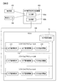
- FIG. 1 is a block diagram showing the configuration of an automotive electronic control device mounted on a vehicle, that is, an ECU. Although a plurality of ECUs are mounted on the vehicle, only one ECU is shown in FIG.
- the ECU 100 includes a CPU 10, a RAM 11, and a flash memory 12.
- the flash memory 12 includes a log storage area 13 in which log information of the ECU 100 is stored.
- the flash memory 12 stores a program 14 for operating the ECU 100.
- the program 14 is expanded in the RAM 11 and executed by the CPU 10.
- the program 14 is composed of 20 software modules (hereinafter referred to as modules) A to T described later.
- the program 14 is one executable file, and each of the software modules A to T is an object file.
- Software modules communicate with each other to exchange information and activate functions. In the following, it is assumed that modules are connected by a node that is a virtual communication path.
- FIG. 2 is a conceptual diagram of the log storage condition generation device and the ECU 100 according to the first embodiment.
- FIG. 2 only a part of the software modules A to T constituting the program 14 is illustrated. Since all the software modules have the same configuration, the following description will be made using the software module A.
- Log information acquired by each software module is stored in the log storage area 13.
- the software module A includes a log acquisition condition 111, a log management function 112, and other functions 113.
- the log management function 112 acquires log information according to the description of the log acquisition condition 111 and stores it in the log storage area 13.
- the source code of the log management function 112 does not describe conditions for acquiring log information
- the software module is obtained after combining the source code of the log management function 112 and the information described in the log acquisition condition 111.
- A is compiled.
- the software module A which is an object file, acquires log information according to the description of the log acquisition condition 111 and stores it in the log storage area 13. Since the log management function 112 does not include the log acquisition condition 111, it has the following advantages. For example, when entrusting production of a module including the log management function 112, it is only necessary to comprehensively indicate conditions for acquiring log information at the stage of entrusting production of the module, and it is not necessary to determine conditions for acquiring log information.
- the log acquisition condition 111 is generated by a log storage condition generation device 102 described later.
- the log storage condition generation device 102 is a computer that includes an input unit 102a and a CPU, ROM, and RAM (not shown).
- the CPU expands and executes a program for performing operations described later stored in the ROM in the RAM.
- the generation unit 102b represents the function of this program as a functional block.
- the input unit 102a is a communication interface or a keyboard, and receives a property table 103 and an acquisition rule 104 described later.
- the property table 103 is a list showing the properties of the software module, and consists of the development vendor, quality level, and verification viewpoint.
- “Development vendor” is information that can at least determine whether or not the company is in-house.
- the “quality level” is an index representing quality, and is determined based on, for example, the safety level of IEC61508 to which the module is compatible.
- the “verification viewpoint” is a test viewpoint in which the verification has been completed in the module, that is, a test item confirmed to operate normally.
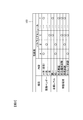
- FIG. 3 shows an example of the property table 103.
- FIG. 3 shows a list of development vendors, quality levels, and verification viewpoints for the software modules A to T.
- the “development vendor” indicates whether the software module is manufactured by company ⁇ , which is its own company, or company ⁇ or ⁇ , which is not its company.
- the “quality level” is indicated as “high” when the safety level of IEC61508 is 3 or more, and “low” otherwise.
- “Verification viewpoint” is indicated by a mark “ ⁇ ” in the test viewpoint where the verification is completed among the form verification, the state transition test, the load test, and the timing test.
- the property table 103 indicates that the software module A is developed by company ⁇ , which is its own, has a low quality level, and is verified by a timing test.
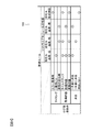
- the acquisition rule 104 is a list of conditions for generating the log acquisition condition 111 based on the property of the software module. For example, when the acquisition rule 104 satisfies at least one of the case where the vendor is not a company, the quality level is low, and the case where the verification viewpoint is low, the frequency of acquiring log information is increased or the information acquired as log information Is specified to increase An example of the acquisition rule 104 is shown in FIG.
- the acquisition rule 104 is composed of a combination of log acquisition conditions and software module properties.
- the log acquisition condition includes a timing, acquisition contents, and an erase condition.
- the timing indicates the timing at which the log information is acquired, and there are, for example, “when an error occurs”, “every period”, and “when a variable changes”. “When an error occurs” indicates that log information is acquired every time an error occurs in the ECU in which the software module is incorporated. “Every cycle” indicates that log information is acquired every predetermined control cycle of the ECU. “When variable changes” indicates that log information is acquired when a variable held by the software module changes.
- the acquired content indicates the content acquired as log information, and there are, for example, “time stamp”, “processing content”, and “variable value”.
- the “time stamp” indicates information related to time, and indicates the current time or the number of seconds elapsed from the start of operation.
- Processing content indicates the content of the processing executed last by the software module. For example, “processing module C is called” or “value 5 is output to module D”.
- “Variable value” indicates a combination of a variable name and its value held by the software module.
- the generation unit 102b of the log storage condition generation device 102 performs the following operation. In other words, the generation unit 102b determines whether the property of any software module described in the acquisition rule 104 corresponds to each module described in the property table 103. If there is a corresponding property, the generation unit 102b outputs the log acquisition condition 111 of the module. The generation unit 102b blanks the log acquisition condition 111 when there is no corresponding property. In this case, log information of the module is not acquired.
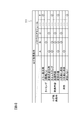
- FIG. 5 shows the log acquisition conditions 111 of the software modules A to T generated by the generation unit 102b based on the property table 103 shown in FIG. 3 and the acquisition rules 104 shown in FIG.
- the log management function 112 acquires log information according to the description of the log acquisition condition 111 and stores it in the log storage area 13. In the log storage area 13, in addition to the log information acquired by the log management function 112, the serial number of the log information and the name of the module that acquired the log information are stored.
- FIG. 6 is a diagram illustrating an example of log information stored in the log storage area 13.
- FIG. 6 corresponds to the log acquisition conditions shown in FIG. 5.
- Module A stores time stamps and variable values
- module B stores time stamps, processing contents, and variable values
- module C stores The processing contents are saved.
- the log storage condition generation device 102 generates a condition for storing log information of a plurality of software modules included in the electronic control unit for an automobile, that is, the ECU 100, that is, a log acquisition condition 111.
- the log storage condition generation device 102 has an input unit 102a to which the properties of a plurality of software modules, that is, the property table 103 and the acquisition rule 104 are input, and the software modules based on the properties of the software modules and the storage rules.
- a condition generation unit that determines information to be acquired that is, a generation unit 102.
- log information acquisition conditions can be set according to the nature of the software module.
- software modules developed by a plurality of vendors coexist, if logs of all modules are output by matching the level with the module having the lowest quality level, excessive logs are output.
- the log storage condition generation device 102 can set the acquisition conditions of each log information according to the property of the software module, such a problem does not occur.
- the log storage condition generation device 102 can generate the log acquisition condition 111 without requiring an operation by an operator.
- the property of the software module described in the table 103 includes at least one of vendor, quality level, and verification viewpoint. Therefore, the generation unit 102b can set log information acquisition conditions based on whether or not the module vendor is in-house, the level of quality level, and the verification viewpoint.
- the quality level is a safety level according to the IEC standard 61508. Therefore, the quality level can be evaluated using objective criteria.
- Modification 1 In the first embodiment, the property table 103 and the acquisition rule 104 are input from the input unit 102a. However, either the property table 103 or the acquisition rule 104 may be stored in the ROM of the log storage condition generation device 102.
- Modification 2 In the first embodiment, the “quality level” in the property table 103 is determined based on the safety level of IEC61508. However, it may be determined based on other criteria.
- FIGS. 1-10 A second embodiment of the log storage condition generation device according to the present invention will be described with reference to FIGS.
- the same components as those in the first embodiment are denoted by the same reference numerals, and different points will be mainly described. Points that are not particularly described are the same as those in the first embodiment.
- This embodiment is different from the first embodiment mainly in that only some software modules have a log management function.
- FIG. 7 is a conceptual diagram of the log storage condition generation device 102 and the ECU 100 according to the second embodiment.
- a connection table 105 described later is also input to the log storage condition generation device 102.
- a group of a plurality of software modules that realize a certain function is referred to as a function block. All software modules transmit processing contents and variable values in response to requests from other software modules in the same functional block. Only the software module determined by the log storage condition generation device 102 includes the log management function 112.
- FIG. 8 shows an example of the connection between software modules and the configuration of functional blocks. As described above, modules are connected by a node that is a virtual communication path.
- the name of the software module shown in FIG. 8 is the identifier of the functional block to which the first character belongs, and the second character is the identifier in the functional block.
- the functional block A is composed of three software modules Aa, Ab, and Ac.
- FIG. 8 shows seven functional blocks A to G.
- the module Aa is connected to the module Ab and the module Ab in the same functional block by a node.
- the module Aa is connected to the module Ba belonging to the functional block B by an interface and a node.
- the interface provides a connection between functional blocks. That is, the module Aa is connected to the function blocks B to G through the interface.
- the log storage condition generation apparatus 102 receives a connection table 105 indicating connections between modules and functional block configurations.
- FIG. 9 is a connection table 105 corresponding to the connections between modules and the functional block configuration shown in FIG.
- the connection of the modules belonging to the functional blocks A to B that is, the presence / absence of a node between the modules is expressed by the presence / absence of a mark.
- the connection with the modules belonging to the function blocks C to G is omitted.
- the log storage condition generation device 102 determines a module including the log management function 112 for each functional block based on the connection table 105.
- the module having the largest number of connected nodes in the functional block is determined as the module having the log management function 112. If the number of connected nodes is the same, the module connected to the interface is given priority. For example, in the function block A, since the number of nodes in the same block connected to the module Aa is 2, and the module Ab and the module Ac are 1, the module Aa is determined as a module having the log management function 112. In the function block B, since the number of nodes connected to both the module Bb and the module Bc is 2, the module Bb connected to the interface is determined as a module having the log management function 112.
- the log storage condition generation device 102 sets the log acquisition conditions of all modules of the functional block to which the module belongs to the module having the determined log management function 112. Thereby, in the example of FIG. 8, the log management function 112 of the module Aa acquires the log information of the modules Aa, Ab, and Ac and stores them in the log storage area 13.
- the log information stored in the log storage area 13 is the same as that in the first embodiment.
- FIG. 10 is a flowchart illustrating the operation of the generation unit 102b according to the second embodiment.
- step S201 log acquisition conditions for all modules are calculated, and the process proceeds to step S202.
- a specific calculation method is as described in the first embodiment.
- step S202 a module having the maximum number of connections in the same group is calculated for each function group, and the process proceeds to step S203.
- step S203 for each function group, the log management function 112 is provided in the module having the largest number of connections in the same group calculated in step S202, and the process proceeds to step S204.
- step S204 log acquisition conditions corresponding to all modules in the functional block to which the module belongs are set in the module provided with the log management function 112 in step S203, and the flowchart shown in FIG. 10 ends.
- a connection relationship between a plurality of software modules connected by a node is input to the input unit 102a as a connection table 105.
- the generation unit 102b determines a software module for acquiring a log based on the number of nodes connected to the software module. Therefore, log information can be collected efficiently by the generation unit 102b determining a module to which many nodes are connected in the same function group as a module having a log acquisition function.
- the generation unit 102b determines a software module for acquiring a log based on the number of nodes connected to the software module belonging to another group, that is, another functional block. Since a lot of information is collected in modules connected to modules belonging to other functional blocks, log information can be efficiently collected by acquiring log information in that module.
- the log acquisition condition is determined based on the property of the module.
- log acquisition conditions may be determined based on the properties of adjacent modules.
- the acquisition rule 104 may include, as one of the determination conditions, whether the vendor of the adjacent module is the company.
- the property table 103 further indicates whether the transmission of processing contents and variable values according to requests from other modules in the same functional block is performed as a property of the module ( Hereinafter, whether or not log information transfer is possible) and whether or not the log management function 112 is provided may be set.
- Log information relating to a module for which log information transfer is not possible is obtained when the module itself has the log management function 112 or indirectly obtained from another module. For example, when a variable is output from module A that cannot transfer log information to module B that can transfer log information, information is indirectly obtained as follows. That is, although the variable output as the log information of module A cannot be obtained, the variable output as the log information of module B is obtained indirectly by obtaining the variable input as the log information of module B.
- the acquisition rule 104 cannot be provided with the log management function 112 due to the nature of the adjacent module, and the processing content according to a request from another module in the same functional block If it is impossible to transmit the value of a variable, it may be specified that the following operation is performed. That is, the value of a variable and an operation command that the module transmits / receives to / from its adjacent module are acquired. According to this modification, when the source code of a module is unknown and provided in a format that cannot be changed, such as a library format, log information regarding the module can be acquired.
- the program 14 is composed of seven functional blocks A to G.
- the number of functional blocks constituting the program 14 is not limited to this.
- the program 14 may be composed of only one functional block, and the program 14 may include only one log management function 112.
- FIGS. 1 and 2 A third embodiment of the log storage condition generation device according to the present invention will be described with reference to FIGS.
- the same components as those in the first embodiment are denoted by the same reference numerals, and different points will be mainly described. Points that are not particularly described are the same as those in the first embodiment.
- This embodiment is different from the first embodiment mainly in that the log acquisition condition is not incorporated into the module.
- FIG. 11 is a block diagram showing a configuration of a certain ECU 100 in the third embodiment.
- a log acquisition condition 111 is stored in the flash memory 12 of the ECU 100.
- log acquisition conditions for all modules may be collectively stored in one file, or may be stored in individual files for each module.
- FIG. 12 is a conceptual diagram of the log storage condition generation device and the ECU 100 according to the third embodiment.
- the log management function 112 operates based on the description of the log acquisition condition 111 stored in the flash memory 12. That is, the log acquisition condition 111 is not incorporated in the program 14.
- the module can be used as it is.
- a module that is an object file is compiled after the source code of the log management function 112 and the information described in the log acquisition condition 111 are combined. Therefore, in the first embodiment, when the log acquisition condition 111 is changed, it is necessary to compile the module again. In the third embodiment, re-compilation is unnecessary, and the module can be easily reused.
Landscapes
- Engineering & Computer Science (AREA)
- Theoretical Computer Science (AREA)
- General Engineering & Computer Science (AREA)
- Quality & Reliability (AREA)
- Physics & Mathematics (AREA)
- General Physics & Mathematics (AREA)
- Computer Hardware Design (AREA)
- Debugging And Monitoring (AREA)
Abstract
ログ保存条件生成装置は、自動車用電子制御装置に含まれる複数のソフトウエアモジュールのログ情報を保存する条件を生成するログ保存条件生成装置であって、複数のソフトウエアモジュールの性質、および保存ルールが入力される入力部と、ソフトウエアモジュールの性質および保存ルールに基づき、各々のソフトウエアモジュールに関するログ情報を取得するタイミング、および取得する情報を決定する条件生成部とを備える。
Description
本発明は、ログ保存条件生成装置、およびログ保存条件生成方法に関する。
近年、組込みソフトウェアの大規模化、複雑化が進んでおり、既存のソフトウエアモジュールを組合せて機能を実現することが一般に行われる。自動車などの車両制御装置に用いられるElectronic Control Unit(ECU)も同様であり、ECUでは、複数のベンダーが開発した品質レベルの異なるソフトウエアモジュールが混在する構成が多くみられる。ECUに不具合が発生した際に、その原因を究明するためにログ情報を保存することが有用であるが、ECUが使用できるリソースは非常に限定的なので、多くの情報をログとして出力することができない。
特許文献1には、正常データと異常データとを比較して相違集合を算出し、障害発生条件を算出できるかを判断し、障害発生条件の算出の可否に基づき取得する入出力信号を変化させる発明が開示されている。
特許文献1には、正常データと異常データとを比較して相違集合を算出し、障害発生条件を算出できるかを判断し、障害発生条件の算出の可否に基づき取得する入出力信号を変化させる発明が開示されている。
特許文献1に記載の発明では、ソフトウエアモジュールの性質に応じたログ取得の設定ができない。
本発明の第1の態様によると、自動車用電子制御装置に含まれる複数のソフトウエアモジュールのログ情報を保存する条件を生成するログ保存条件生成装置は、複数のソフトウエアモジュールの性質、および保存ルールが入力される入力部と、ソフトウエアモジュールの性質および保存ルールに基づき、各々のソフトウエアモジュールに関するログ情報を取得するタイミング、および取得する情報を決定する条件生成部とを備える。
本発明の第2の態様によると、自動車用電子制御装置を構成する複数のソフトウエアモジュールのログ情報を保存する条件をコンピュータが生成するログ保存条件生成方法は、複数のソフトウエアモジュールの性質、および保存ルールをコンピュータに入力することと、入力された複数のソフトウエアモジュールの性質および入力された保存ルールに基づき、複数のソフトウエアモジュールに関するログ情報を取得するタイミング、および取得する情報をコンピュータが生成することとを有する。
本発明の第2の態様によると、自動車用電子制御装置を構成する複数のソフトウエアモジュールのログ情報を保存する条件をコンピュータが生成するログ保存条件生成方法は、複数のソフトウエアモジュールの性質、および保存ルールをコンピュータに入力することと、入力された複数のソフトウエアモジュールの性質および入力された保存ルールに基づき、複数のソフトウエアモジュールに関するログ情報を取得するタイミング、および取得する情報をコンピュータが生成することとを有する。
本発明によれば、ソフトウエアモジュールの性質に応じてログ情報の取得条件を設定できる。
(第1の実施の形態)
以下、図1~6を参照して、本発明によるログ保存条件生成装置の第1の実施の形態を説明する。
以下、図1~6を参照して、本発明によるログ保存条件生成装置の第1の実施の形態を説明する。
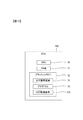
図1は、車両に搭載される自動車用電子制御装置、すなわちECUの構成を示すブロック図である。車両には複数のECUが搭載されるが、図1には1つのECUのみを記載している。ECU100は、CPU10、RAM11、およびフラッシュメモリ12から構成される。フラッシュメモリ12は、当該ECU100のログ情報が保存されるログ保存領域13を含む。フラッシュメモリ12には、ECU100を動作させるプログラム14が保存される。プログラム14は、RAM11に展開されてCPU10により実行される。このプログラム14は、後述するA~Tの20のソフトウエアモジュール(以下、モジュール)から構成される。たとえば、プログラム14は1つの実行可能ファイルであり、A~Tの各々のソフトウエアモジュールは、オブジェクトファイルである。ソフトウエアモジュールは相互に通信を行い、情報の授受や関数の起動などを行う。以下では、仮想的な通信路であるノードによりモジュール同士が接続されているとする。
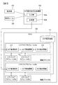
図2は、第1の実施の形態に係るログ保存条件生成装置およびECU100の概念図である。
図2では、プログラム14を構成するソフトウエアモジュールA~Tのうち、一部のみを図示している。いずれのソフトウエアモジュールも構成が同じなので、以下ではソフトウエアモジュールAを用いて説明する。それぞれのソフトウエアモジュールが取得するログ情報は、ログ保存領域13に保存される。
図2では、プログラム14を構成するソフトウエアモジュールA~Tのうち、一部のみを図示している。いずれのソフトウエアモジュールも構成が同じなので、以下ではソフトウエアモジュールAを用いて説明する。それぞれのソフトウエアモジュールが取得するログ情報は、ログ保存領域13に保存される。
ソフトウエアモジュールAは、ログ取得条件111と、ログ管理関数112と、その他の関数113とを含む。ログ管理関数112は、ログ取得条件111の記述に従ってログ情報を取得し、ログ保存領域13に保存する。たとえば、ログ管理関数112のソースコードにはログ情報を取得する条件は記載されておらず、ログ管理関数112のソースコードとログ取得条件111に記載された情報とを結合させてからソフトウエアモジュールAがコンパイルされる。これにより、オブジェクトファイルであるソフトウエアモジュールAは、ログ取得条件111の記述に従ってログ情報を取得し、ログ保存領域13に保存する。
ログ管理関数112にはログ取得条件111が含まれていないため、以下のような利点を有する。たとえばログ管理関数112を含むモジュールを制作委託する場合に、モジュールの制作を委託する段階ではログ情報を取得する条件を網羅的に示せばよく、ログ情報を取得する条件を確定させる必要がない。
ログ管理関数112にはログ取得条件111が含まれていないため、以下のような利点を有する。たとえばログ管理関数112を含むモジュールを制作委託する場合に、モジュールの制作を委託する段階ではログ情報を取得する条件を網羅的に示せばよく、ログ情報を取得する条件を確定させる必要がない。
ログ取得条件111は、後述するログ保存条件生成装置102により生成される。
ログ保存条件生成装置102は、入力部102aおよび不図示のCPU、ROM、RAMを備える計算機である。CPUは、ROMに保存されている後述する動作を行うプログラムをRAMに展開して実行する。生成部102bは、このプログラムの機能を機能ブロックとして表したものである。入力部102aは、通信インタフェースまたはキーボードであり、後述する性質表103および取得ルール104が入力される。
ログ保存条件生成装置102は、入力部102aおよび不図示のCPU、ROM、RAMを備える計算機である。CPUは、ROMに保存されている後述する動作を行うプログラムをRAMに展開して実行する。生成部102bは、このプログラムの機能を機能ブロックとして表したものである。入力部102aは、通信インタフェースまたはキーボードであり、後述する性質表103および取得ルール104が入力される。
性質表103は、ソフトウエアモジュールの性質を示した一覧表であり、開発ベンダー、品質レベル、検証観点から構成される。「開発ベンダー」は、少なくとも自社か否かを判断できる情報である。「品質レベル」は、品質を表す指標であり、たとえば当該モジュールが適合するIEC61508の安全度水準に基づき決定される。「検証観点」は、当該モジュールにおいて検証が完了しているテスト観点、すなわち正常に動作することが確認されたテスト項目である。
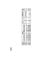
図3に性質表103の一例を示す。図3には、ソフトウエアモジュールA~Tについて、開発ベンダー、品質レベル、検証観点の一覧が示されている。「開発ベンダー」は、ソフトウエアモジュールの製造が、自社であるα社、または自社ではないβ社、γ社のいずれであるかが示される。「品質レベル」は、IEC61508の安全度水準が3以上の場合には「高い」、それ以外の場合は「低い」と示される。「検証観点」は、形式検証、状態遷移試験、負荷試験、タイミング試験、のうち検証が完了しているテスト観点には○の印が示される。性質表103には、ソフトウエアモジュールAは、自社であるα社により開発され、品質レベルは低く、タイミング試験による検証が行われていることが示されている。
取得ルール104は、ソフトウエアモジュールの性質に基づきログ取得条件111を生成する条件の一覧である。取得ルール104により、たとえばベンダーが自社でない場合、品質レベルが低い場合、および検証観点が少ない場合の少なくとも1つを満たす場合に、ログ情報を取得する頻度を増加させる、またはログ情報として取得する情報を増加させる旨が規定される。
図4に取得ルール104の一例を示す。取得ルール104は、ログ取得条件と、ソフトウエアモジュールの性質との組み合わせから構成される。
ログ取得条件は、タイミングと、取得内容と、消去条件とから構成される。
図4に取得ルール104の一例を示す。取得ルール104は、ログ取得条件と、ソフトウエアモジュールの性質との組み合わせから構成される。
ログ取得条件は、タイミングと、取得内容と、消去条件とから構成される。
タイミングは、ログ情報を取得するタイミングを示すものであり、たとえば「エラー発生時」、「一周期ごと」、「変数の変化時」の3つがある。「エラー発生時」は、ソフトウエアモジュールが組み込まれているECUに、何らかのエラーが発生するたびにログ情報が取得されることを示す。「一周期ごと」は、ECUの所定の制御周期ごとにログ情報が取得されることを示す。「変数の変化時」は、当該ソフトウエアモジュールが保持する変数が変化した時にログ情報が取得されることを示す。
取得内容は、ログ情報として取得する内容を示すものであり、たとえば「タイムスタンプ」、「処理内容」、「変数の値」の3つがある。「タイムスタンプ」とは、時間に関する情報を示すものであり、現在時刻または稼働開始からの経過秒数を示す。「処理内容」とは、ソフトウエアモジュールが最後に実行した処理の内容を示すものであり、たとえば“モジュールCを呼びだした”旨や“モジュールDに値5を出力した”旨である。「変数の値」とは、当該ソフトウエアモジュールが保持する変数の名称とその値の組合せを示す。
(動作例)
ログ保存条件生成装置102の動作例を説明する。
ログ保存条件生成装置102の生成部102bは、入力部102aに性質表103および取得ルール104が入力されると、以下の動作を行う。すなわち、生成部102bは、性質表103に記載されたモジュールごとに取得ルール104に記載されたいずれかのソフトウエアモジュールの性質に該当するか否かを判断する。生成部102bは、該当する性質があるとそのモジュールのログ取得条件111として出力する。生成部102bは、該当する性質がない場合はログ取得条件111をブランクにする。この場合、そのモジュールのログ情報は取得されない。
ログ保存条件生成装置102の動作例を説明する。
ログ保存条件生成装置102の生成部102bは、入力部102aに性質表103および取得ルール104が入力されると、以下の動作を行う。すなわち、生成部102bは、性質表103に記載されたモジュールごとに取得ルール104に記載されたいずれかのソフトウエアモジュールの性質に該当するか否かを判断する。生成部102bは、該当する性質があるとそのモジュールのログ取得条件111として出力する。生成部102bは、該当する性質がない場合はログ取得条件111をブランクにする。この場合、そのモジュールのログ情報は取得されない。
図5は、図3に示した性質表103と図4に示した取得ルール104に基づいて、生成部102bが生成したソフトウエアモジュールA~Tのログ取得条件111を示す。たとえばソフトウエアモジュールAは、自社かつ品質が低いというソフトウエアモジュールの性質に該当するので、変数が変化するたびに、タイムスタンプ、および変数の値が取得され、1年後に消去される。
ログ管理関数112は、ログ取得条件111の記述に従ってログ情報を取得し、ログ保存領域13に保存する。ログ保存領域13には、ログ管理関数112が取得したログ情報に加えて、ログ情報の通し番号、およびログ情報を取得したモジュールの名称が保存される。
ログ管理関数112は、ログ取得条件111の記述に従ってログ情報を取得し、ログ保存領域13に保存する。ログ保存領域13には、ログ管理関数112が取得したログ情報に加えて、ログ情報の通し番号、およびログ情報を取得したモジュールの名称が保存される。
図6は、ログ保存領域13に保存されるログ情報の一例を示す図である。図6は、図5に示すログ取得条件に対応しており、モジュールAはタイムスタンプと変数の値が保存され、モジュールBはタイムスタンプ、処理内容、および変数の値が保存され、モジュールCは処理内容が保存される。
上述した実施の形態によれば、次の作用効果が得られる。
(1)本発明にかかるログ保存条件生成装置102は、自動車用電子制御装置、すなわちECU100に含まれる複数のソフトウエアモジュールのログ情報を保存する条件、すなわちログ取得条件111を生成する。ログ保存条件生成装置102は、複数のソフトウエアモジュールの性質、すなわち性質表103、および取得ルール104が入力される入力部102aと、ソフトウエアモジュールの性質および保存ルールに基づき、各々のソフトウエアモジュールに関するログ情報を取得するタイミング、および取得する情報を決定する条件生成部、すなわち生成部102とを備える。
ログ保存条件生成装置102をこのように構成したので、ソフトウエアモジュールの性質に応じてログ情報の取得条件を設定できる。
複数のベンダーにより開発されたソフトウエアモジュールが混在する場合に、最も品質レベルの低いモジュールに水準を合せて全モジュールのログを出力すると、過剰にログが出力される。しかし、ログ保存条件生成装置102はソフトウエアモジュールの性質に応じて、それぞれのログ情報の取得条件を設定できるので、このような問題が生じない。
ログ保存条件生成装置102は、オペレータによる操作を必要とせずにログ取得条件111を生成することができる。
(2)性質表103に記載されるソフトウエアモジュールの性質とは、ベンダー、品質レベル、検証観点の少なくとも1つを含む。
そのため生成部102bは、モジュールのベンダーが自社であるか否か、品質レベルの高低、および検証観点に基づき、ログ情報の取得条件を設定できる。
(3)品質レベルとは、IEC規格61508における安全度水準である。
そのため、客観的な基準を用いて品質レベルを評価することができる。
そのため生成部102bは、モジュールのベンダーが自社であるか否か、品質レベルの高低、および検証観点に基づき、ログ情報の取得条件を設定できる。
(3)品質レベルとは、IEC規格61508における安全度水準である。
そのため、客観的な基準を用いて品質レベルを評価することができる。
(変形例1)
第1の実施の形態では、入力部102aから性質表103および取得ルール104が入力された。しかし、性質表103および取得ルール104のいずれか一方が、ログ保存条件生成装置102のROMに保存されていてもよい。
(変形例2)
第1の実施の形態では、性質表103の「品質レベル」は、IEC61508の安全度水準に基づき決定された。しかし、他の基準に基づいて決定されてもよい。
第1の実施の形態では、入力部102aから性質表103および取得ルール104が入力された。しかし、性質表103および取得ルール104のいずれか一方が、ログ保存条件生成装置102のROMに保存されていてもよい。
(変形例2)
第1の実施の形態では、性質表103の「品質レベル」は、IEC61508の安全度水準に基づき決定された。しかし、他の基準に基づいて決定されてもよい。
(第2の実施の形態)
図7~10を参照して、本発明によるログ保存条件生成装置の第2の実施の形態を説明する。以下の説明では、第1の実施の形態と同じ構成要素には同じ符号を付して相違点を主に説明する。特に説明しない点については、第1の実施の形態と同じである。本実施の形態では、主に、一部のソフトウエアモジュールのみがログ管理関数を備える点で、第1の実施の形態と異なる。
図7~10を参照して、本発明によるログ保存条件生成装置の第2の実施の形態を説明する。以下の説明では、第1の実施の形態と同じ構成要素には同じ符号を付して相違点を主に説明する。特に説明しない点については、第1の実施の形態と同じである。本実施の形態では、主に、一部のソフトウエアモジュールのみがログ管理関数を備える点で、第1の実施の形態と異なる。
図7は、第2の実施の形態に係るログ保存条件生成装置102およびECU100の概念図である。ログ保存条件生成装置102には、性質表103および取得ルール104に加えて、後述する接続表105も入力される。
以下では、ある機能を実現する複数のソフトウエアモジュールのグループを機能ブロックと呼ぶ。いずれのソフトウエアモジュールも、同じ機能ブロック内の他のソフトウエアモジュールの要求に応じて処理内容や変数の値を送信する。ログ保存条件生成装置102が決定したソフトウエアモジュールのみログ管理関数112を備える。
以下では、ある機能を実現する複数のソフトウエアモジュールのグループを機能ブロックと呼ぶ。いずれのソフトウエアモジュールも、同じ機能ブロック内の他のソフトウエアモジュールの要求に応じて処理内容や変数の値を送信する。ログ保存条件生成装置102が決定したソフトウエアモジュールのみログ管理関数112を備える。
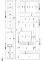
図8に、ソフトウエアモジュール同士の接続、および機能ブロックの構成の一例を示す。前述のとおり、仮想的な通信路であるノードによりモジュール同士が接続される。図8に示すソフトウエアモジュールの名称は、一文字目が属する機能ブロックの識別子、2文字目が機能ブロック内の識別子である。たとえば、機能ブロックAは、3つのソフトウエアモジュールAa、Ab、Acから構成される。図8にはA~Gの7つの機能ブロックが記載される。
モジュールAaは、同一機能ブロック内のモジュールAbおよびモジュールAbとノードにより接続される。モジュールAaは、機能ブロックBに属するモジュールBa、およびインタフェースとノードにより接続される。インタフェースは、機能ブロック同士の接続を提供する。すなわちモジュールAaは、インタフェースを通じて機能ブロックB~Gと接続される。
ログ保存条件生成装置102には、性質表103および取得ルール104に加えて、モジュール間の接続および機能ブロックの構成を示す接続表105が入力される。
ログ保存条件生成装置102には、性質表103および取得ルール104に加えて、モジュール間の接続および機能ブロックの構成を示す接続表105が入力される。
図9は、図8に示したモジュール同士の接続、および機能ブロックの構成に対応する接続表105である。図9では機能ブロックA~Bに属するモジュールの接続、すなわちモジュール間のノードの有無が○印の有無で表現される。図9では機能ブロックC~Gに属するモジュールとの接続の記載は省略されている。
ログ保存条件生成装置102は、接続表105に基づき、機能ブロックごとにログ管理関数112を備えるモジュールを決定する。機能ブロック内における接続されるノードが最も多いモジュールがログ管理関数112を備えるモジュールとして決定され、接続されるノード数が同一であれば、インタフェースに接続されるモジュールが優先される。たとえば、機能ブロックAでは、モジュールAaに接続される同一ブロック内のノード数が2、モジュールAbおよびモジュールAcは1なので、モジュールAaがログ管理関数112を備えるモジュールとして決定される。機能ブロックBでは、モジュールBbおよびモジュールBcのいずれも接続されるノード数が2なので、インタフェースに接続されるモジュールBbがログ管理関数112を備えるモジュールとして決定される。
ログ保存条件生成装置102は、決定したログ管理関数112を備えるモジュールにそのモジュールが属する機能ブロックの全てのモジュールのログ取得条件を設定する。これにより、図8の例ではモジュールAaのログ管理関数112は、モジュールAa、Ab、Acのログ情報を取得し、ログ保存領域13に保存する。ログ保存領域13に保存されるログ情報は、第1の実施の形態と同様である。
(フローチャート)
ログ保存条件生成装置102の生成部102bの動作を、フローチャートを用いて説明する。以下に説明する各ステップの実行主体は、ログ保存条件生成装置102のCPUである。ログ保存条件生成装置102は、入力部102aに性質表103、取得ルール104、および接続表105が入力されると動作を開始する。
図10は、第2の実施の形態における生成部102bの動作を示すフローチャートである。
ログ保存条件生成装置102の生成部102bの動作を、フローチャートを用いて説明する。以下に説明する各ステップの実行主体は、ログ保存条件生成装置102のCPUである。ログ保存条件生成装置102は、入力部102aに性質表103、取得ルール104、および接続表105が入力されると動作を開始する。
図10は、第2の実施の形態における生成部102bの動作を示すフローチャートである。
ステップS201において、全てのモジュールのログ取得条件を算出し、ステップS202に進む。具体的な算出方法は、第1の実施の形態で説明したとおりである。
ステップS202において、機能グループごとに、同一グループ内で接続数が最大のモジュールを算出し、ステップS203に進む。
ステップS203において、機能グループごとに、ステップS202において算出した同一グループ内で接続数が最大のモジュールに、ログ管理関数112を備えさせステップS204に進む。
ステップS204において、ステップS203においてログ管理関数112を備えさせたモジュールに、そのモジュールが属する機能ブロック内の全てのモジュールに対応するログ取得条件を設定し、図10に示すフローチャートを終了する。
ステップS202において、機能グループごとに、同一グループ内で接続数が最大のモジュールを算出し、ステップS203に進む。
ステップS203において、機能グループごとに、ステップS202において算出した同一グループ内で接続数が最大のモジュールに、ログ管理関数112を備えさせステップS204に進む。
ステップS204において、ステップS203においてログ管理関数112を備えさせたモジュールに、そのモジュールが属する機能ブロック内の全てのモジュールに対応するログ取得条件を設定し、図10に示すフローチャートを終了する。
上述した実施の形態によれば、次の作用効果が得られる。
(1)入力部102aには、ノードにより接続される複数のソフトウエアモジュール同士の接続関係が接続表105として入力される。生成部102bは、ソフトウエアモジュールに接続されるノードの数に基づき、ログを取得するソフトウエアモジュールを決定する。
そのため、生成部102bが同一機能グループ内で多くのノードが接続されたモジュールをログ取得関数を備えるモジュールとして決定することで、効率よくログ情報を収集することができる。
(1)入力部102aには、ノードにより接続される複数のソフトウエアモジュール同士の接続関係が接続表105として入力される。生成部102bは、ソフトウエアモジュールに接続されるノードの数に基づき、ログを取得するソフトウエアモジュールを決定する。
そのため、生成部102bが同一機能グループ内で多くのノードが接続されたモジュールをログ取得関数を備えるモジュールとして決定することで、効率よくログ情報を収集することができる。
(2)入力部102aには、複数のソフトウエアモジュールが機能に基づきグループ分けされた情報が接続表105として入力される。生成部102bは、他のグループ、すなわち他の機能ブロックに属するソフトウエアモジュールと接続されるノードの数に基づき、ログを取得するソフトウエアモジュールを決定する。
他の機能ブロックに属するモジュールと接続されるモジュールには多くの情報が集まるので、そのモジュールにおいてログ情報を取得することにより、効率よくログ情報を収集することができる。
他の機能ブロックに属するモジュールと接続されるモジュールには多くの情報が集まるので、そのモジュールにおいてログ情報を取得することにより、効率よくログ情報を収集することができる。
(第2の実施の形態の変形例1)
第1の実施の形態では、当該モジュールの性質に基づきログ取得条件が決定された。しかし、隣接するモジュールの性質に基づきログ取得条件が決定されてもよい。
たとえば、取得ルール104が隣接するモジュールのベンダーが自社であるか否かを判断条件の1つに含んでもよい。
第1の実施の形態では、当該モジュールの性質に基づきログ取得条件が決定された。しかし、隣接するモジュールの性質に基づきログ取得条件が決定されてもよい。
たとえば、取得ルール104が隣接するモジュールのベンダーが自社であるか否かを判断条件の1つに含んでもよい。
(第2の実施の形態の変形例2)
上記、第2の実施の形態の変形例1において、さらに、性質表103にモジュールの性質として、同じ機能ブロック内の他のモジュールからの要求に応じた処理内容や変数の値の送信の可否(以下、ログ情報転送の可否)、およびログ管理関数112の具備の可否が設定されていてもよい。
ログ情報転送が不可能なモジュールに関するログ情報は、当該モジュール自身がログ管理関数112を備える場合か、他のモジュールから間接的に得られる場合に得られる。たとえば、ログ情報転送が不可能なモジュールAから、ログ情報転送が可能なモジュールBに変数が出力された場合に、以下のように間接的に情報が得られる。すなわち、モジュールAのログ情報として出力した変数を得ることはできないが、モジュールBのログ情報として入力された変数を得ることにより、間接的にモジュールAが出力した変数が間接的に得られる。
このような場合に、取得ルール104には、隣接するモジュールの性質が、ログ管理関数112を備えることが不可能であり、なおかつ、同じ機能ブロック内の他のモジュールからの要求に応じた処理内容や変数の値の送信が不可能であれば、以下の動作を行う旨を規定してもよい。すなわち、当該モジュールがその隣接するモジュールとの間で送受信する変数の値、および動作指令を取得する。
この変形例によれば、モジュールのソースコードが不明であり、ライブラリ形式など変更が不可能な形式で提供された場合に、そのモジュールに関するログ情報を取得することができる。
この変形例によれば、モジュールのソースコードが不明であり、ライブラリ形式など変更が不可能な形式で提供された場合に、そのモジュールに関するログ情報を取得することができる。
(第2の実施の形態の変形例3)
第2の実施の形態では、プログラム14がA~Gの7つの機能ブロックから構成された。しかし、プログラム14を構成する機能ブロックの数はこれに限定されない。たとえば、プログラム14が1つの機能ブロックのみから構成され、プログラム14が1つのログ管理関数112のみを備えてもよい。
第2の実施の形態では、プログラム14がA~Gの7つの機能ブロックから構成された。しかし、プログラム14を構成する機能ブロックの数はこれに限定されない。たとえば、プログラム14が1つの機能ブロックのみから構成され、プログラム14が1つのログ管理関数112のみを備えてもよい。
(第3の実施の形態)
図11~12を参照して、本発明によるログ保存条件生成装置の第3の実施の形態を説明する。以下の説明では、第1の実施の形態と同じ構成要素には同じ符号を付して相違点を主に説明する。特に説明しない点については、第1の実施の形態と同じである。本実施の形態では、主に、ログ取得条件がモジュールに組み込まれない点で、第1の実施の形態と異なる。
図11~12を参照して、本発明によるログ保存条件生成装置の第3の実施の形態を説明する。以下の説明では、第1の実施の形態と同じ構成要素には同じ符号を付して相違点を主に説明する。特に説明しない点については、第1の実施の形態と同じである。本実施の形態では、主に、ログ取得条件がモジュールに組み込まれない点で、第1の実施の形態と異なる。
図11は、第3の実施の形態における、ある1つのECU100の構成を示すブロック図である。ECU100のフラッシュメモリ12には、ログ取得条件111が保存される。ただし、ログ取得条件111は、全てのモジュールに関するログ取得条件がまとめて1つのファイルに保存されてもよいし、モジュールごとに個別のファイルに保存されてもよい。
図12は、第3の実施の形態に係るログ保存条件生成装置およびECU100の概念図である。ログ管理関数112は、フラッシュメモリ12に保存されるログ取得条件111の記載に基づき動作する。すなわち、プログラム14にはログ取得条件111が組み込まれていない。
図12は、第3の実施の形態に係るログ保存条件生成装置およびECU100の概念図である。ログ管理関数112は、フラッシュメモリ12に保存されるログ取得条件111の記載に基づき動作する。すなわち、プログラム14にはログ取得条件111が組み込まれていない。
そのため、ログ取得条件111が変更された場合でも、オブジェクトファイルであるモジュールを再構成する必要がなく、そのまま利用することができる。一方、第1の実施の形態では、ログ管理関数112のソースコードとログ取得条件111に記載された情報とが結合されてからオブジェクトファイルであるモジュールがコンパイルされる。そのため、第1の実施の形態ではログ取得条件111が変更されると、モジュールを再度コンパイルする必要があった。第3の実施の形態では、再度のコンパイルが不要であり、モジュールを簡便に再利用することができる。
上述した各実施の形態および変形例は、それぞれ組み合わせてもよい。
上記では、種々の実施の形態および変形例を説明したが、本発明はこれらの内容に限定されるものではない。本発明の技術的思想の範囲内で考えられるその他の態様も本発明の範囲内に含まれる。
上記では、種々の実施の形態および変形例を説明したが、本発明はこれらの内容に限定されるものではない。本発明の技術的思想の範囲内で考えられるその他の態様も本発明の範囲内に含まれる。
次の優先権基礎出願の開示内容は引用文としてここに組み込まれる。
日本国特許出願2015年第109467号(2015年5月29日出願)
日本国特許出願2015年第109467号(2015年5月29日出願)
13 … ログ保存領域
100 … ECU
102 … ログ保存条件生成装置
102 … 生成部
102a … 入力部
102b … 生成部
103 … 性質表
104 … 取得ルール
105 … 接続表
111 … ログ取得条件
112 … ログ管理関数
100 … ECU
102 … ログ保存条件生成装置
102 … 生成部
102a … 入力部
102b … 生成部
103 … 性質表
104 … 取得ルール
105 … 接続表
111 … ログ取得条件
112 … ログ管理関数
Claims (6)
- 自動車用電子制御装置に含まれる複数のソフトウエアモジュールのログ情報を保存する条件を生成するログ保存条件生成装置であって、
前記複数のソフトウエアモジュールの性質、および保存ルールが入力される入力部と、
前記ソフトウエアモジュールの性質および前記保存ルールに基づき、各々の前記ソフトウエアモジュールに関するログ情報を取得するタイミング、および取得する情報を決定する条件生成部とを備えるログ保存条件生成装置。 - 請求項1に記載のログ保存条件生成装置において、
前記ソフトウエアモジュールの性質とは、
ベンダー、品質レベル、検証観点の少なくとも1つを含み、
前記条件生成部は、ソフトウエアモジュールの性質、および前記保存ルールに基づき、
ベンダーが自社でない場合、品質レベルが低い場合、および検証観点が少ない場合の少なくとも1つを満たす場合に、
ログ情報を取得する頻度を増加させる、またはログ情報として取得する情報を増加させる、ログ保存条件生成装置。 - 請求項2に記載のログ保存条件生成装置において、
前記品質レベルとは、IEC規格61508における安全度水準であるログ保存条件生成装置。 - 請求項1に記載のログ保存条件生成装置において、
前記入力部には、ノードにより接続される前記複数のソフトウエアモジュール同士の接続関係がさらに入力され、
前記条件生成部は、前記ソフトウエアモジュールに接続されるノードの数に基づき、ログ情報を取得するソフトウエアモジュールを決定するログ保存条件生成装置。 - 請求項4に記載のログ保存条件生成装置において、
前記入力部には、前記複数のソフトウエアモジュールが機能に基づきグループ分けされた情報がさらに入力され、
前記条件生成部は、他の前記グループに属するソフトウエアモジュールと接続されるノードの数に基づき、ログ情報を取得するソフトウエアモジュールを決定するログ保存条件生成装置。 - 自動車用電子制御装置を構成する複数のソフトウエアモジュールのログ情報を保存する条件をコンピュータが生成するログ保存条件生成方法であって、
前記複数のソフトウエアモジュールの性質、および保存ルールをコンピュータに入力することと、
入力された前記複数のソフトウエアモジュールの性質および入力された前記保存ルールに基づき、前記複数のソフトウエアモジュールに関するログ情報を取得するタイミング、および取得する情報をコンピュータが生成することとを有する、ログ保存条件生成方法。
Applications Claiming Priority (2)
| Application Number | Priority Date | Filing Date | Title |
|---|---|---|---|
| JP2015109467A JP6607705B2 (ja) | 2015-05-29 | 2015-05-29 | ログ保存条件生成装置、ログ保存条件生成方法 |
| JP2015-109467 | 2015-05-29 |
Publications (1)
| Publication Number | Publication Date |
|---|---|
| WO2016194673A1 true WO2016194673A1 (ja) | 2016-12-08 |
Family
ID=57441497
Family Applications (1)
| Application Number | Title | Priority Date | Filing Date |
|---|---|---|---|
| PCT/JP2016/065147 Ceased WO2016194673A1 (ja) | 2015-05-29 | 2016-05-23 | ログ保存条件生成装置、ログ保存条件生成方法 |
Country Status (2)
| Country | Link |
|---|---|
| JP (1) | JP6607705B2 (ja) |
| WO (1) | WO2016194673A1 (ja) |
Families Citing this family (1)
| Publication number | Priority date | Publication date | Assignee | Title |
|---|---|---|---|---|
| JP7886360B2 (ja) * | 2024-01-31 | 2026-07-07 | 株式会社オービック | ログポリシー管理装置、ログポリシー管理方法及びログポリシー管理プログラム |
Citations (4)
| Publication number | Priority date | Publication date | Assignee | Title |
|---|---|---|---|---|
| JP2000311102A (ja) * | 1999-04-27 | 2000-11-07 | Denso Corp | 電子制御装置 |
| JP2008210135A (ja) * | 2007-02-26 | 2008-09-11 | Tokyo Metropolis | ログ取得方法、ログ取得システム及びログ取得プログラム |
| WO2012011145A1 (ja) * | 2010-07-20 | 2012-01-26 | 株式会社 日立製作所 | ソフトウェア保守支援装置及びそれにより検証した電子制御装置 |
| WO2012111167A1 (ja) * | 2011-02-14 | 2012-08-23 | 株式会社日立製作所 | トレース情報取得方法、コンピュータシステム及びプログラム |
-
2015
- 2015-05-29 JP JP2015109467A patent/JP6607705B2/ja active Active
-
2016
- 2016-05-23 WO PCT/JP2016/065147 patent/WO2016194673A1/ja not_active Ceased
Patent Citations (4)
| Publication number | Priority date | Publication date | Assignee | Title |
|---|---|---|---|---|
| JP2000311102A (ja) * | 1999-04-27 | 2000-11-07 | Denso Corp | 電子制御装置 |
| JP2008210135A (ja) * | 2007-02-26 | 2008-09-11 | Tokyo Metropolis | ログ取得方法、ログ取得システム及びログ取得プログラム |
| WO2012011145A1 (ja) * | 2010-07-20 | 2012-01-26 | 株式会社 日立製作所 | ソフトウェア保守支援装置及びそれにより検証した電子制御装置 |
| WO2012111167A1 (ja) * | 2011-02-14 | 2012-08-23 | 株式会社日立製作所 | トレース情報取得方法、コンピュータシステム及びプログラム |
Non-Patent Citations (1)
| Title |
|---|
| YUKO MUTO ET AL.: "Improvement of a Visualization Technique for Unit Testing and Static Checking Using Caller-Callee Relationship and Its Evaluation", LECTURE NOTE/SOFTWARE-GAKU 37 SOFTWARE KOGAKU NO KISO XVIII, 30 November 2011 (2011-11-30), Tokyo, pages 163 - 168 * |
Also Published As
| Publication number | Publication date |
|---|---|
| JP6607705B2 (ja) | 2019-11-20 |
| JP2016224646A (ja) | 2016-12-28 |
Similar Documents
| Publication | Publication Date | Title |
|---|---|---|
| JP6964274B2 (ja) | 監視装置、監視システム及び監視方法 | |
| US10241852B2 (en) | Automated qualification of a safety critical system | |
| US11899788B2 (en) | Attack tree generation device, attack tree generation method, and computer readable medium | |
| US20160080462A1 (en) | Data processing method and apparatus in service-oriented architecture system, and the service-oriented architecture system | |
| JP2016057969A (ja) | プログラム検査装置、ソフトウェア検査装置、sat制約条件データ、記憶媒体 | |
| US20210173938A1 (en) | Security risk reduction method and security risk reduction system | |
| EP3722945B1 (en) | Program operation system and program operation method | |
| CN114556238B (zh) | 用于在云计算环境中生成资产信息的数字表示的方法和系统 | |
| JP6607705B2 (ja) | ログ保存条件生成装置、ログ保存条件生成方法 | |
| JP6664880B2 (ja) | 電子デバイスを備える電子システム、そのようなシステムを備える回路遮断器、デバイス間に非互換性がある場合に偏差指標を生成するための方法および関連するコンピュータ・プログラム製品 | |
| KR101593835B1 (ko) | Plc 시스템 | |
| US9646252B2 (en) | Template clauses based SAT techniques | |
| US10078638B2 (en) | Secure hyper transfer of large files | |
| US20120317526A1 (en) | Verification method, computer-readable recording medium, and design verification apparatus | |
| US20150277858A1 (en) | Performance evaluation device, method, and medium for information system | |
| JP5989193B1 (ja) | ソフトウェア更新システム | |
| JP2007141072A (ja) | トレース情報出力装置 | |
| JP6766962B2 (ja) | 変更手順生成装置、変更手順生成方法および変更手順生成プログラム | |
| KR102545640B1 (ko) | 철도차량 시스템의 소프트웨어 개발 시스템 및 방법 | |
| US20260094018A1 (en) | Generation method, computer-readable recording medium, and information processing device | |
| Grus | Implementation of Integration Testing Test Cases Generation Tool | |
| WO2025009195A1 (ja) | 状態異常検知システム、状態異常検知方法およびプログラム | |
| JP2010097328A (ja) | ループ最適化システム、ループ最適化方法、及びループ最適化用プログラム | |
| US11645061B2 (en) | Construction automation tool for automatic creation of a procedure generation program for changing complex systems | |
| CN120745075A (zh) | 车辆总线数据的生成方法、装置、电子设备及存储介质 |
Legal Events
| Date | Code | Title | Description |
|---|---|---|---|
| 121 | Ep: the epo has been informed by wipo that ep was designated in this application |
Ref document number: 16803108 Country of ref document: EP Kind code of ref document: A1 |
|
| NENP | Non-entry into the national phase |
Ref country code: DE |
|
| 122 | Ep: pct application non-entry in european phase |
Ref document number: 16803108 Country of ref document: EP Kind code of ref document: A1 |