WO2016194299A1 - 電力変換装置 - Google Patents
電力変換装置 Download PDFInfo
- Publication number
- WO2016194299A1 WO2016194299A1 PCT/JP2016/002254 JP2016002254W WO2016194299A1 WO 2016194299 A1 WO2016194299 A1 WO 2016194299A1 JP 2016002254 W JP2016002254 W JP 2016002254W WO 2016194299 A1 WO2016194299 A1 WO 2016194299A1
- Authority
- WO
- WIPO (PCT)
- Prior art keywords
- value
- control unit
- current threshold
- current
- switching elements
- Prior art date
- Legal status (The legal status is an assumption and is not a legal conclusion. Google has not performed a legal analysis and makes no representation as to the accuracy of the status listed.)
- Ceased
Links
Images




Classifications
-
- H—ELECTRICITY
- H02—GENERATION; CONVERSION OR DISTRIBUTION OF ELECTRIC POWER
- H02M—APPARATUS FOR CONVERSION BETWEEN AC AND AC, BETWEEN AC AND DC, OR BETWEEN DC AND DC, AND FOR USE WITH MAINS OR SIMILAR POWER SUPPLY SYSTEMS; CONVERSION OF DC OR AC INPUT POWER INTO SURGE OUTPUT POWER; CONTROL OR REGULATION THEREOF
- H02M7/00—Conversion of AC power input into DC power output; Conversion of DC power input into AC power output
- H02M7/02—Conversion of AC power input into DC power output without possibility of reversal
- H02M7/04—Conversion of AC power input into DC power output without possibility of reversal by static converters
- H02M7/12—Conversion of AC power input into DC power output without possibility of reversal by static converters using discharge tubes with control electrode or semiconductor devices with control electrode
-
- H—ELECTRICITY
- H02—GENERATION; CONVERSION OR DISTRIBUTION OF ELECTRIC POWER
- H02M—APPARATUS FOR CONVERSION BETWEEN AC AND AC, BETWEEN AC AND DC, OR BETWEEN DC AND DC, AND FOR USE WITH MAINS OR SIMILAR POWER SUPPLY SYSTEMS; CONVERSION OF DC OR AC INPUT POWER INTO SURGE OUTPUT POWER; CONTROL OR REGULATION THEREOF
- H02M7/00—Conversion of AC power input into DC power output; Conversion of DC power input into AC power output
- H02M7/02—Conversion of AC power input into DC power output without possibility of reversal
- H02M7/04—Conversion of AC power input into DC power output without possibility of reversal by static converters
- H02M7/12—Conversion of AC power input into DC power output without possibility of reversal by static converters using discharge tubes with control electrode or semiconductor devices with control electrode
- H02M7/21—Conversion of AC power input into DC power output without possibility of reversal by static converters using discharge tubes with control electrode or semiconductor devices with control electrode using devices of a triode or transistor type requiring continuous application of a control signal
Definitions
- the present disclosure relates to a power conversion device.
- a device described in Patent Document 1 below is known as a device that performs power conversion using a rectifier circuit.
- the rectifier circuit switching rectifier circuit
- the AC power is converted into DC power by switching between the ON state and the OFF state of these switching elements.
- the rectifier circuit of the device receives an on signal (gate signal) from the control device (timing control device), thereby turning on some switching elements while turning off other switching elements.
- the control device transmits an ON signal based on the relationship between the voltage of AC power and the threshold value, and periodically switches between the ON state and the OFF state of the switching element. . That is, the control device transmits an ON signal to the rectifier circuit to turn on some of the switching elements based on the fact that the voltage of the AC power has exceeded the threshold value.
- the control device stops transmission of the ON signal to the rectifier circuit in order to turn off some of the switching elements based on the threshold voltage.
- the threshold value used when stopping the transmission of the ON signal to the rectifier circuit is set to be smaller than the threshold value used when transmitting the ON signal. This makes it possible for the device to reliably switch the switching element to the OFF state, and as a result, it is possible to prevent the backflow of current in the rectifier circuit and the decrease in power conversion efficiency.
- This disclosure is intended to provide a power conversion device that can improve the conversion efficiency from AC power to DC power by turning off the switching element of the rectifier circuit at an appropriate timing.
- a power conversion device includes a plurality of switching elements, a rectifier circuit that converts AC power into DC power by switching between an ON state and an OFF state of the plurality of switching elements, and the rectifier circuit Control for transmitting an ON signal to the rectifier circuit based on a relationship between a current detection unit that detects a value of an alternating current supplied to the current detection unit, a value of the alternating current detected by the current detection unit, and a current threshold value A part.
- the control unit sets at least a first current threshold and a second current threshold having an absolute value larger than the first current threshold as the current threshold, and the absolute value of the alternating current value is the first current threshold.
- the absolute value of the second current threshold value used when the control unit stops transmission of the on signal is greater than the absolute value of the first current threshold value used when the control unit transmits the on signal. Is big. Therefore, according to the power conversion device described above, even if a delay time occurs in the detection of the value of the alternating current by the current detection unit and the stop of transmission of the on signal based on the detection, it is considered earlier It becomes possible to stop the transmission of the ON signal at the timing. As a result, according to the power conversion device, it is possible to improve the conversion efficiency from AC power to DC power by turning off the switching element of the rectifier circuit at an appropriate timing.
- the above power converter it is possible to provide a power converter capable of improving the conversion efficiency from AC power to DC power by turning off the switching element of the rectifier circuit at an appropriate timing.
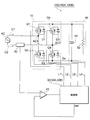
- FIG. 1 is a circuit diagram illustrating a power conversion device according to the first embodiment of the present disclosure.
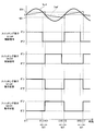
- FIG. 2 is a time chart showing an example of control by the control unit according to the first embodiment.
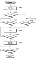
- FIG. 3 is a flowchart showing a flow of processing by the control unit according to the first embodiment.
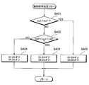
- FIG. 4 is a flowchart showing a flow of processing by the control unit according to the first embodiment.
- FIG. 5 is a time chart illustrating an example of control by the control unit according to the second embodiment.
- FIG. 6 is a flowchart showing a flow of processing by the control unit according to the second embodiment.
- FIG. 1 is a circuit diagram illustrating a power conversion device according to the first embodiment of the present disclosure.
- FIG. 2 is a time chart showing an example of control by the control unit according to the first embodiment.
- FIG. 3 is a flowchart showing a flow of processing by the control unit according to the first embodiment.
- FIG. 4 is a flowchart showing a flow of processing by
- FIG. 7 is a flowchart showing a flow of processing by the control unit according to the second embodiment.
- FIG. 8 is a time chart showing an example of control by the control unit according to the third embodiment.
- FIG. 9 is a flowchart showing a flow of processing by the control unit according to the third embodiment.
- the power conversion device 100 is provided as a device that converts AC power supplied from an AC power source AC into DC power.
- the DC power converted by the power conversion device 100 is supplied to a load 50 having a capacitor 51 and a resistor 52 for smoothing.
- the power conversion apparatus 100 includes a rectifier circuit 10, a current detection unit 20, a control unit 30, and a comparison circuit 40.
- the input side of the rectifier circuit 10 is electrically connected to the AC power supply AC, and the output side thereof is electrically connected to the load 50.
- the rectifier circuit 10 includes switching elements Q1, Q2, Q3, and Q4.
- MOSFETs are employed as the switching elements Q1, Q2, Q3, and Q4.
- the present disclosure is not limited to this, and switching elements that can be switched between an on state and an off state. If it is, arbitrary things can be adopted. For example, JFET, MESFET, IGBT, GTO, power transistor, etc. can be employed.
- Switching element Q1 and switching element Q2 are connected in series.
- one terminal AC1 of the AC power supply AC is connected between the switching element Q1 and the switching element Q2.
- a diode D1 is connected in parallel with the switching element Q1, and a diode D2 is connected in parallel with the switching element Q2.
- Switching element Q3 and switching element Q4 are connected in series. Further, the other terminal AC2 of the AC power supply AC is connected between the switching element Q3 and the switching element Q4. A diode D3 is connected in parallel with the switching element Q3, and a diode D4 is connected in parallel with the switching element Q4.
- the current detection unit 20 is disposed between the AC power supply AC and the other terminal AC2 of the AC power supply AC described above.
- the current detection unit 20 detects an alternating current supplied from the alternating current power supply AC to the rectifier circuit 10. Further, the current detection unit 20 generates a detection signal corresponding to the detected value of the alternating current (hereinafter referred to as “alternating current value”) and transmits the detection signal to the outside.
- the control unit 30 is electrically connected to the switching elements Q1, Q2, Q3, and Q4 via signal lines L1, L2, L3, and L4, and transmits a control signal to the switching elements Q1, Q2, Q3, and Q4. Equipment. Specifically, the control unit 30 generates an ON signal according to PWM (Pulse Width Modulation) control based on an input from the comparison circuit 40 described later, and transmits the ON signal to the switching elements Q1, Q2, Q3, and Q4. , Switch between their on state and off state.
- the control unit 30 is configured to operate by executing a program centering on a CPU (Central Processing Unit), but may be configured to operate by hardware logic including circuit elements.
- CPU Central Processing Unit
- the comparison circuit 40 is a circuit that is electrically connected to the current detection unit 20 and the control unit 30.
- the comparison circuit 40 compares the value of the alternating current detected by the current detection unit 20 with a current threshold Iref described later, generates a signal corresponding to the comparison result, and transmits the signal to the control unit 30. That is, the control unit 30 transmits an ON signal based on the detection of the alternating current by the current detection unit 20.
- the power conversion device 100 configured as described above performs full-wave rectification of AC power supplied from the AC power supply AC by switching the switching elements Q1, Q2, Q3, and Q4 between the on state and the off state.
- the control unit 30 switches the switching elements Q1, Q4. Send the ON signal only to.
- the switching elements Q1 and Q4 are turned on by receiving this on signal, but the switching elements Q2 and Q3 remain in the off state.
- the control unit 30 applies only to the switching elements Q2 and Q3. Send on signal.
- the switching elements Q2 and Q3 are turned on by receiving this on signal, but the switching elements Q1 and Q4 remain in the off state.
- a delay time may occur in the detection of the alternating current by the current detection unit 20 and the stop of transmission of the ON signal from the control unit 30 based on the detection. Due to such factors, if the switching elements Q1, Q2, Q3, and Q4 originally remain in the ON state even at the timing when they should be switched to the OFF state, there is a possibility that a reverse current flows in the rectifier circuit 10. For this reason, there exists a possibility of causing the fall of the conversion efficiency of the power converter device 100, and the damage of switching element Q1, Q2, Q3, Q4.
- the power conversion device 100 is devised in terms of the timing at which the control unit 30 transmits the on signal and the timing at which the transmission of the on signal is stopped.
- this device will be described with reference to FIGS.
- FIG. 2 the time change of the value Iout of the alternating current detected by the current detection unit 20 is shown in the uppermost stage.
- control signals transmitted from the control unit 30 to the switching elements Q1, Q2, Q3, and Q4 are shown. That is, “ON” indicates a state in which the control unit 30 transmits an ON signal to each switching element, and “OFF” indicates a state in which the control unit 30 does not transmit an ON signal to each switching element. Show. Further, the lower part of FIG. 2 shows the on state or the off state of the switching elements Q1, Q2, Q3, and Q4.
- the control unit 30 determines a current threshold value Iref that changes with time, and outputs the current threshold value Iref to the comparison circuit 40.
- the comparison circuit 40 compares the alternating current value Iout detected by the current detection unit 20 with the current threshold value Iref, generates a signal corresponding to the comparison result, and transmits the signal to the control unit 30.
- control unit 30 Based on the signal received from comparison circuit 40, control unit 30 transmits an ON signal to switching elements Q1, Q4 or switching elements Q2, Q3.
- the current threshold value Iref is zero at time t11.
- the comparison circuit 40 When the alternating current value Iout exceeds the current threshold value Iref (zero) at time t11, the comparison circuit 40 generates a signal corresponding to this magnitude relationship and transmits it to the control unit 30.
- the control unit 30 that has received the signal transmits an ON signal only to the switching elements Q1 and Q4. Thereby, switching elements Q1 and Q4 are switched from the off state to the on state.
- the control unit 30 After time t11, the control unit 30 gradually increases the current threshold value Iref.
- the comparison circuit 40 compares the alternating current value Iout with the current threshold value Iref even while the current threshold value Iref is increasing.
- this time td1 corresponds to a delay time from when the control unit 30 stops transmitting the ON signal to the switching elements Q1 and Q4 until the switching elements Q1 and Q4 are actually turned off.
- the alternating current value Iout changes from a positive value to a negative value.
- the change of the alternating current value Iout from the positive value to the negative value and the change of the alternating current value Iout from the negative value to the positive value are referred to as “zero cross”.
- the control unit 30 sets the current threshold value Iref that has been gradually increased to zero based on the detection of a zero crossing in which the alternating current value Iout changes from a positive value to a negative value.
- the control unit 30 applies only to the switching elements Q2 and Q3. Send on signal. Thereby, switching elements Q2 and Q3 are switched from the off state to the on state. At time t13, switching of the switching elements Q1, Q4 from the on state to the off state and switching of the switching elements Q2, Q3 from the off state to the on state are performed substantially simultaneously, thereby suppressing the loss of AC power. Can do.
- the control unit 30 After time t13, the control unit 30 gradually decreases the current threshold value Iref.
- the comparison circuit 40 compares the alternating current value Iout with the current threshold value Iref even while the current threshold value Iref is decreasing.
- the control unit 30 stops transmitting the ON signal to the switching elements Q2 and Q3.
- a delay time occurs from the timing when the control unit 30 stops transmitting the ON signal until the switching elements Q2 and Q3 are actually turned off.
- this time td1 corresponds to a delay time from when the control unit 30 stops transmitting the ON signal to the switching elements Q2 and Q3 until the switching elements Q2 and Q3 are actually turned off.
- control unit 30 sets the current threshold value Iref that has been gradually increased to zero based on the detection of the zero crossing in which the alternating current value Iout changes from a negative value to a positive value. .
- the control unit 30 applies only to the switching elements Q1 and Q4. Send on signal. Thereby, switching elements Q1 and Q4 are switched from the off state to the on state.
- switching of the switching elements Q2 and Q3 from the on-state to the off-state and switching of the switching elements Q1 and Q4 from the off-state to the on-state are performed substantially simultaneously, thereby suppressing the loss of AC power. Can do.
- control unit 30 repeats the control described so far in accordance with the frequency of the AC power supply AC. That is, at times t16 and t17, control similar to that at times t12 and t13 in which the relationship between the alternating current value Iout and the current threshold value Iref is the same is performed.
- step S101 the control unit 30 sets zero as the initial value of the current threshold value Iref.
- step S102 the control unit 30 determines whether or not the alternating current value Iout is a positive value. That is, the control unit 30 determines whether or not current is flowing from the AC power supply AC in the direction indicated by the arrow C1 (see FIG. 1). When it determines with alternating current value Iout being a positive value (S102: YES), the control part 30 progresses to the process of step S103.
- control unit 30 increases the current threshold value Iref by a constant A in step S103.
- the constant A is a positive value.
- control unit 30 determines whether or not the above-described zero cross is detected in step S104.
- the zero crossing here is one in which the alternating current value Iout changes from a positive value to a negative value.
- control part 30 returns to the process of step S103 mentioned above. That is, the control unit 30 increases the current threshold Iref by the constant A until it is determined that a zero cross is detected (S104: YES).
- control unit 30 If it is determined that a zero cross is detected (S104: YES), the control unit 30 returns to the process of step S101 described above. As a result, the current threshold value Iref that has been increased is reset to zero.
- step S102 when it is determined in step S102 that the alternating current value Iout is not a positive value (S102: NO), that is, a current flows from the alternating current power supply AC in the direction indicated by the arrow C2 (see FIG. 1). If it is determined that there is, the control unit 30 proceeds to the process of step S105.
- control unit 30 decreases the current threshold value Iref by a constant A in step S105.
- the constant A is a positive value.
- step S106 the control unit 30 determines whether or not the above-described zero cross is detected.
- the zero crossing here is one in which the alternating current value Iout changes from a negative value to a positive value.
- the control part 30 returns to the process of step S105 mentioned above. That is, the control unit 30 decreases the current threshold Iref by a constant A until it is determined that a zero cross is detected (S106: YES).
- control unit 30 If it is determined that a zero cross is detected (S106: YES), the control unit 30 returns to the process of step S101 described above. As a result, the current threshold value Iref that has been reduced so far is reset to zero.
- step S201 the control unit 30 determines whether the alternating current value Iout is a positive value. That is, the control unit 30 determines whether or not current is flowing from the AC power supply AC in the direction indicated by the arrow C1 (see FIG. 1). When it determines with the alternating current value Iout being a positive value (S201: YES), the control part 30 progresses to the process of step S202.
- step S202 the control unit 30 determines whether or not the alternating current value Iout is larger than the current threshold value Iref.
- the control unit 30 performs the determination based on the signal received from the comparison circuit 40.
- the control part 30 progresses to the process of step S203.
- step S203 the control unit 30 determines that the switching elements Q1, Q4 are turned on and the switching elements Q2, Q3 are turned off. That is, control unit 30 determines to transmit an ON signal only to switching elements Q1 and Q4.
- step S202 when it is determined in step S202 that the alternating current value Iout is not greater than the current threshold value Iref (S202: NO), the control unit 30 proceeds to the process of step S204.
- step S204 the control unit 30 determines to turn off the switching elements Q1, Q4 and the switching elements Q2, Q3. That is, the control unit 30 determines not to transmit the ON signal.
- step S201 when it is determined in step S201 that the AC current value Iout is not a positive value (S201: NO), that is, a current flows from the AC power supply AC in the direction indicated by the arrow C2 (see FIG. 1). If it is determined that there is, the control unit 30 proceeds to the process of step S205.
- control unit 30 determines whether or not the alternating current value Iout is smaller than the current threshold value Iref in step S205.
- the control unit 30 performs the determination based on the signal received from the comparison circuit 40.
- the control part 30 progresses to the process of step S206.
- step S206 the control unit 30 determines that the switching elements Q1 and Q4 are turned off and the switching elements Q2 and Q3 are turned on. In other words, control unit 30 determines to transmit an ON signal only to switching elements Q2 and Q3.
- step S205 when it is determined in step S205 that the alternating current value Iout is not smaller than the current threshold value Iref (S205: NO), the control unit 30 proceeds to the process of step S207.
- control unit 30 determines to turn off the switching elements Q1, Q4 and the switching elements Q2, Q3 in step S207. That is, the control unit 30 determines not to transmit the ON signal.
- the current threshold used when the control unit stops transmission of the on signal is larger than the absolute value of current threshold Iref (zero) used when control unit 30 transmits the on signal.
- Iref current threshold
- the absolute value of Iref (I12, -I12) is large.
- the power conversion device 100 even when the delay time td1 occurs in the detection of the alternating current by the current detection unit 20 and the stop of the transmission of the on signal based on the detection, an earlier timing is taken into consideration. It becomes possible to stop transmission of the ON signal. As a result, according to the power conversion device 100, the switching elements Q1, Q2, Q3, and Q4 of the rectifier circuit 10 can be turned off at an appropriate timing to improve the conversion efficiency from AC power to DC power. Become.
- control unit 30 gradually changes the current threshold value Iref from zero to I12 and ⁇ I12 with time, and sets the current threshold value Iref to zero at the timing when the alternating current value Iout becomes zero.
- the control unit 30 uses the absolute value of the current threshold value Iref (zero) used when the control unit 30 transmits the on signal to stop the on signal transmission.
- the absolute value of the current threshold value Iref (I12, ⁇ I12) can be increased.
- the current threshold value Iref can be periodically changed according to the frequency of the AC power supplied from the AC power supply AC. It becomes.
- the timing at which the current threshold value Iref is zero is the timing at which the AC current value Iout is zero.
- a predetermined time from when the on-signal transmission is stopped is determined. It may be a timing after (first predetermined time). In this case, the same effect can be obtained.
- the power conversion device 100A (see FIG. 1) according to the second embodiment of the present disclosure will be described with reference to FIGS.
- the control by the control unit 30A is different from that of the control unit 30 according to the first embodiment described above.
- symbol is used and the overlapping description is abbreviate
- control unit 30A has current thresholds Iref1 and Iref2 that change with time. Further, the control unit 30A outputs the current threshold values Iref1 and Iref2 to the comparison circuit 40.
- the comparison circuit 40 compares the alternating current value Iout detected by the current detection unit 20 with the current threshold values Iref1 and Iref2, and generates a signal based on the comparison result and transmits it to the control unit 30A. Based on the signal received from comparison circuit 40, control unit 30A transmits an ON signal to switching elements Q1, Q4 or switching elements Q2, Q3.
- the current threshold value Iref1 is I12
- the current threshold value Iref2 is ⁇ I12.
- the comparison circuit 40 When the alternating current value Iout exceeds the current threshold value Iref1 (I12) at time t21, the comparison circuit 40 generates a signal corresponding to this magnitude relationship and transmits it to the control unit 30A.
- Control unit 30A that has received the signal transmits an ON signal only to switching elements Q1 and Q4. Thereby, switching elements Q1 and Q4 are switched from the off state to the on state.
- control unit 30A After time t21, the control unit 30A maintains the current threshold value Iref1 as I12 and maintains the current threshold value Iref2 as ⁇ I12. Then, after time t0 has elapsed from time t21, control unit 30A changes current threshold value Iref1 to I22 larger than I12, and changes current threshold value Iref2 to ⁇ I22 smaller than ⁇ I12 (absolute value is larger).
- the comparison circuit 40 compares the alternating current value Iout with the current threshold values Iref1 and Iref2 before and after the change of the current threshold values Iref1 and Iref2.
- the control unit 30A stops transmitting the ON signal to the switching elements Q1 and Q4.
- the control unit 30A stops transmitting the ON signal until the switching elements Q1 and Q4 are actually turned off.
- this time td2 corresponds to a delay time from when the control unit 30A stops transmitting the ON signal to the switching elements Q1 and Q4 until the switching elements Q1 and Q4 are actually turned off.
- a zero cross where the alternating current value Iout changes from a positive value to a negative value is detected.
- control unit 30A maintains the current threshold value Iref1 as I22 and maintains the current threshold value Iref2 as ⁇ I22. Then, after time t0 has elapsed from time t22, control unit 30A changes current threshold value Iref1 to I12 that is smaller than I22, and changes current threshold value Iref2 to ⁇ I12 that is larger than ⁇ I22 (the absolute value is smaller).
- control unit 30A transmits an ON signal only to switching elements Q2 and Q3. . Thereby, switching elements Q2 and Q3 are switched from the off state to the on state. It takes a short time from switching the switching elements Q1, Q4 from the on-state to the off-state at time t23 to switching the switching elements Q2, Q3 from the off-state to the on-state at time t24. Can be suppressed.
- control unit 30A After time t24, the control unit 30A maintains the current threshold value Iref1 as I12 and maintains the current threshold value Iref2 as ⁇ I12. Then, after time t0 has elapsed from time t24, control unit 30A changes current threshold value Iref1 to I22 larger than I12, and changes current threshold value Iref2 to ⁇ I22 smaller than ⁇ I12 (absolute value is larger).
- the comparison circuit 40 compares the alternating current value Iout with the current threshold values Iref1 and Iref2 before and after the change of the current threshold values Iref1 and Iref2.
- the control unit 30A stops transmitting the ON signal to the switching elements Q2 and Q3.
- a delay time occurs from when the control unit 30A stops transmitting the ON signal until the switching elements Q2 and Q3 are actually turned off.
- the control unit 30A After time t25, the control unit 30A maintains the current threshold value Iref1 as I22 and maintains the current threshold value Iref2 as ⁇ I22. Then, after the elapse of a predetermined time t0 from time t25, the control unit 30A changes the current threshold value Iref1 to I12 smaller than I22, and changes the current threshold value Iref2 larger than ⁇ I22 (absolute value is small) to ⁇ I12. .
- the comparison circuit 40 compares the alternating current value Iout with the current threshold values Iref1 and Iref2 before and after the change of the current threshold values Iref1 and Iref2.
- this time td2 corresponds to a delay time from when the control unit 30A stops transmitting the ON signal to the switching elements Q2 and Q3 until the switching elements Q2 and Q3 are actually turned off.
- a zero crossing in which the alternating current value Iout changes from a negative value to a positive value is detected.
- the control unit 30A transmits an ON signal only to the switching elements Q1 and Q4. Thereby, switching elements Q1 and Q4 are switched from the off state to the on state.
- the switching elements Q2 and Q3 are switched from the on state to the off state and the switching elements Q1 and Q4 are switched from the off state to the on state at substantially the same time, thereby suppressing the loss of AC power. Can do.
- control unit 30A repeats the control described so far in accordance with the frequency of the AC power supply AC. That is, at time t28, t29, and t30, control similar to that at times t22, t23, and t24 in which the relationship between the alternating current value Iout and the current threshold values Iref1 and Iref2 is the same is performed.
- step S301 the control unit 30A sets I12 as the initial value of the current threshold value Iref1, and sets -I12 as the initial value of the current threshold value Iref2.
- step S302 the control unit 30A determines whether or not the alternating current value Iout is a positive value. That is, control unit 30A determines whether or not a current is flowing from AC power supply AC in the direction indicated by arrow C1 (see FIG. 1). When it is determined that the alternating current value Iout is a positive value (S302: YES), the control unit 30A proceeds to the process of step S303.
- step S303 the control unit 30A determines whether or not the alternating current value Iout is larger than the current threshold value Iref1 (I12).
- the control unit 30A stands by. And when it determines with alternating current value Iout being larger than electric current threshold value Iref1 (I12) (S303: YES), control part 30A progresses to the process of step S304.
- step S302 when it is determined in step S302 that the alternating current value Iout is not a positive value (S302: NO), the control unit 30A proceeds to the process of step S308.
- step S308 the control unit 30A determines whether or not the alternating current value Iout is smaller than the current threshold value Iref2 ( ⁇ I12) (the absolute value is large). When it is determined that the alternating current value Iout is not smaller than the current threshold value Iref2 ( ⁇ I12) (S308: NO), the control unit 30A stands by. When it is determined that the alternating current value Iout is smaller than the current threshold value Iref2 ( ⁇ I12) (S308: YES), the control unit 30A proceeds to the process of step S304.
- control unit 30A adds a constant e to the time t in step S304.
- This constant e is a positive value.
- step S305 the control unit 30A determines whether the time t is greater than the time t0.
- This time t0 is a predetermined constant and is the same as the time t0 described with reference to FIG.
- the control unit 30A returns to the process of step S304. That is, the control unit 30A increases the time t by a constant e until it determines that the time t is greater than the time t0 (S305: YES). If it is determined that the time t is greater than the time t0 (S305: YES), the control unit 30A proceeds to the process of step S306.
- step S306 the control unit 30A changes the current threshold value Iref1 to I22 and changes the current threshold value Iref2 to -I22.
- step S307 the control unit 30A determines whether the above-described zero cross is detected. When it is determined that the zero cross is not detected (S307: NO), the control unit 30A stands by.
- step S307 When it is determined in step S307 that a zero cross has been detected (S307: YES), the control unit 30A returns to the process of step S301 described above. As a result, again, the current threshold value Iref1 is set to I12, and the current threshold value Iref2 is set to ⁇ I12.
- step S401 the control unit 30A determines whether or not the alternating current value Iout is larger than the current threshold value Iref1. When it is determined that the alternating current value Iout is not greater than the current threshold value Iref1 (S401: NO), the control unit 30A proceeds to the process of step S402.
- step S402 the control unit 30A determines whether or not the alternating current value Iout is larger than the current threshold value Iref2 and smaller than the current threshold value Iref1.
- the control unit 30A proceeds to the process of step S403.
- step S403 the control unit 30A determines to turn off the switching elements Q1, Q4 and the switching elements Q2, Q3. That is, the control unit 30A determines not to transmit the ON signal.
- step S402 when it is determined in step S402 that the alternating current value Iout is not larger than the current threshold value Iref2 and smaller than the current threshold value Iref1 (S402: NO), the control unit 30A performs the process of step S404. move on.
- step S404 the control unit 30A determines that the switching elements Q1, Q4 are turned off and the switching elements Q2, Q3 are turned on. That is, control unit 30A determines to transmit an ON signal only to switching elements Q2 and Q3.
- step S401 when it is determined in step S401 that the alternating current value Iout is larger than the current threshold value Iref1 (S401: YES), the control unit 30A proceeds to the process of step S405.
- step S405 the control unit 30A determines that the switching elements Q1, Q4 are turned on and the switching elements Q2, Q3 are turned off. That is, control unit 30A determines to transmit the ON signal only to switching elements Q1 and Q4.
- control unit 30A causes predetermined time t0 from the timing when the absolute value of AC current value Iout exceeds the absolute value of current threshold values Iref1 (I12) and Iref2 ( ⁇ I12). After the (second predetermined time) elapses, the current threshold values Iref1 and Iref2 are changed from I12 and ⁇ I12 to I22 and ⁇ I22.
- the control unit 30A also determines a predetermined time t0 (first time) from the timing when the absolute value of the alternating current value Iout detected by the current detection unit 20 falls below the absolute values of the current threshold values Iref1 (I22) and Iref2 ( ⁇ I22). 3), the current threshold values Iref1 and Iref2 are changed from I22 and ⁇ I22 to I12 and ⁇ I12.
- the control unit 30A can turn on the signal more than the absolute values of the current thresholds Iref1 (I12) and Iref2 ( ⁇ I12) used when the control unit 30A transmits the on signal.
- the absolute values of the current threshold values Iref1 (I22) and Iref2 ( ⁇ I22) used when stopping the transmission of can be increased. Further, the current threshold values Iref1 and Iref2 can be periodically changed according to the frequency of the AC power supplied from the AC power supply AC.
- the second predetermined time and the third predetermined time described above are set to the same time t0, but the present disclosure is not limited to this. That is, the second predetermined time and the third predetermined time may be different from each other.
- the power conversion device 100B (see FIG. 1) according to the third embodiment of the present disclosure will be described with reference to FIGS.
- the control by the control unit 30B is different from that of the control units 30 and 30A according to the above-described embodiment.
- symbol is used and the overlapping description is abbreviate
- control unit 30B has constant current thresholds ⁇ I23, ⁇ I13, I13, and I23 regardless of time. Further, the control unit 30B outputs the current threshold values ⁇ I23, ⁇ I13, I13, and I23 to the comparison circuit 40.
- the comparison circuit 40 compares the alternating current value Iout detected by the current detection unit 20 with the current thresholds ⁇ I23, ⁇ I13, I13, and I23, generates a signal based on the comparison result, and transmits the signal to the control unit 30B. To do. Based on the signal received from comparison circuit 40, control unit 30B transmits an ON signal to switching elements Q1, Q4 or switching elements Q2, Q3.
- the comparison circuit 40 when the alternating current value Iout exceeds the current threshold value I13 at time t31, the comparison circuit 40 generates a signal corresponding to this magnitude relationship and transmits it to the control unit 30B.
- the control unit 30B that has received the signal transmits an ON signal only to the switching elements Q1 and Q4. Thereby, switching elements Q1 and Q4 are switched from the off state to the on state.
- the control unit 30B stops transmission of the ON signal to the switching elements Q1 and Q4.
- the control unit 30B stops transmitting the ON signal until the switching elements Q1 and Q4 are actually turned off.
- this time td3 corresponds to a delay time from when the control unit 30B stops transmitting the ON signal to the switching elements Q1 and Q4 until the switching elements Q1 and Q4 are actually turned off.
- a zero crossing in which the alternating current value Iout changes from a positive value to a negative value is detected.
- the control unit 30B turns on only the switching elements Q2 and Q3 based on the fact that the alternating current value Iout becomes negative and falls below the current threshold ⁇ I13 (absolute value exceeds). Send a signal. Thereby, switching elements Q2 and Q3 are switched from the off state to the on state. Since switching from the on state to the off state of the switching elements Q1 and Q4 at time t33 and the switching of the switching elements Q2 and Q3 from the off state to the on state at time t34 takes a short time, the loss of AC power is reduced. Can be suppressed.
- the control unit 30B stops transmitting the ON signal to the switching elements Q2 and Q3.
- the control unit 30B stops transmitting the ON signal to the switching elements Q2 and Q3.
- this time td3 corresponds to a delay time from when the control unit 30A stops transmitting the ON signal to the switching elements Q2 and Q3 until the switching elements Q2 and Q3 are actually turned off.
- a zero cross where the alternating current value Iout changes from a negative value to a positive value is detected.
- the control unit 30 repeats the control described so far in accordance with the frequency of the AC power supply AC. That is, at times t37, t38, t39, and t40, the same control as that at times t31, t32, t33, and t34 in which the relationship between the alternating current value Iout and the current threshold values I23 and ⁇ I13 are equal is performed.
- step S501 the control unit 30 determines whether or not the alternating current value Iout is larger than the current threshold value ⁇ I13 and smaller than the current threshold value I13.
- the control unit 30 proceeds to the process of step S502.
- step S502 the control unit 30B determines whether or not the alternating current value Iout is larger than the current threshold value I13.
- the control unit 30B proceeds to the process of step S503.
- control unit 30B determines whether or not AC current value Iout has changed from a state larger than current threshold value I23 to a smaller state (whether AC current value Iout has fallen below current threshold value I23). .
- the control part 30B progresses to the process of step S504.
- step S504 the control unit 30B determines to turn off the switching elements Q1, Q4 and the switching elements Q2, Q3. That is, the control unit 30B determines not to transmit the ON signal.
- step S503 if it is determined in step S503 that the alternating current value Iout has not changed from a state larger than the current threshold value I23 to a smaller state (S503: NO), the control unit 30B proceeds to the process of step S505.
- step S505 the control unit 30B determines that the switching elements Q1 and Q4 are turned on and the switching elements Q2 and Q3 are turned off. That is, control unit 30B determines to transmit an ON signal only to switching elements Q1 and Q4.
- step S502 when it is determined in step S502 that the alternating current value Iout is not larger than the current threshold value I13 (S502: NO), the control unit 30B proceeds to the process of step S506.
- step S506 the control unit 30B determines whether or not the alternating current value Iout is smaller than the current threshold value ⁇ I13.
- the control unit 30B proceeds to the process of step S507.
- control unit 30B determines whether or not AC current value Iout has changed from a state smaller than current threshold ⁇ I23 to a larger state (whether AC current value Iout has exceeded current threshold ⁇ I23) or not. judge.
- the control unit 30B proceeds to the process of step S508.
- step S508 the control unit 30B determines to turn off the switching elements Q1, Q4 and the switching elements Q2, Q3. That is, the control unit 30B determines not to transmit the ON signal.
- step S507 if it is determined in step S507 that the alternating current value Iout has not changed from a state smaller than the current threshold ⁇ I23 to a larger state (S506: NO), the control unit 30B proceeds to the process of step S509.
- step S509 the control unit 30B determines that the switching elements Q1 and Q4 are turned off and the switching elements Q2 and Q3 are turned on. That is, control unit 30B determines to transmit an ON signal only to switching elements Q2 and Q3.
- step S501 If it is determined in step S501 that the alternating current value Iout is larger than the current threshold value ⁇ I13 and smaller than the current threshold value I13 (S501: YES), the control unit 30B performs the process in step S510. move on. Furthermore, when it is determined in step S506 that the alternating current value Iout is not smaller than the current threshold value ⁇ I13 (S506: NO), the control unit 30B proceeds to the process of step S510.
- step S510 the control unit 30B determines to turn off the switching elements Q1, Q4 and the switching elements Q2, Q3. That is, the control unit 30B determines not to transmit the ON signal.
- the current used when control unit 30B stops transmission of the on signal is larger than the absolute values of current threshold values I13 and -I13 used when control unit 30B transmits the on signal.
- the absolute values of the thresholds I23 and -I23 are larger. Therefore, according to the power conversion device 100B, even if the delay time td3 occurs in the detection of the alternating current by the current detection unit 20 and the stop of the transmission of the on signal based on the detection, an earlier timing is taken into consideration. It becomes possible to stop transmission of the ON signal. As a result, it is possible to improve the conversion efficiency from AC power to DC power by turning off the switching element of the rectifier circuit at an appropriate timing.
- each section is expressed as S101, for example.
- each section can be divided into a plurality of subsections, while a plurality of sections can be combined into one section.
- each section configured in this manner can be referred to as a device, module, or means.
Landscapes
- Engineering & Computer Science (AREA)
- Power Engineering (AREA)
- Rectifiers (AREA)
- Inverter Devices (AREA)
Abstract
電力変換装置は、複数のスイッチング素子(Q1,Q2,Q3,Q4)を有し、交流電力を直流電力に変換する整流回路(10)と、交流電流の値(Iout)を検出する電流検出部(20)と、前記交流電流の値と電流閾値の関係に基づいて前記整流回路にオン信号を送信する制御部(30)とを備える。前記制御部は、第1電流閾値と2電流閾値を少なくとも設定し、前記交流電流の値の絶対値が前記第1電流閾値の絶対値を上回ったことに基づいて、前記スイッチング素子の一部をオン状態にするために前記整流回路にオン信号を送信する一方で、前記交流電流の値の絶対値が前記第2電流閾値の絶対値を下回ったことに基づいて、前記スイッチング素子の一部をオフ状態にするために前記整流回路へのオン信号の送信を停止する。
Description
本出願は、2015年6月2日に出願された日本特許出願番号2015-112150号に基づくもので、ここにその記載内容を援用する。
本開示は、電力変換装置に関するものである。
整流回路を用いて電力変換を行う装置として、下記特許文献1に記載のものが知られている。当該装置は、整流回路(スイッチング整流回路)が複数のスイッチング素子(スイッチ)を有しており、これらのスイッチング素子のオン状態とオフ状態とを切り替えることによって、交流電力を直流電力に変換する。
当該装置の整流回路は、制御装置(タイミング制御装置)からオン信号(ゲート信号)を受信することで、一部のスイッチング素子をオン状態にする一方で、他のスイッチング素子をオフ状態にするように動作する。詳細には、下記特許文献1の装置では、制御装置は、交流電力の電圧と閾値との関係に基づいてオン信号を送信し、スイッチング素子のオン状態とオフ状態との切り替えを周期的に行う。つまり、制御装置は、交流電力の電圧が閾値を上回ったことに基づいて、一部のスイッチング素子をオン状態にするために整流回路にオン信号を送信する。一方、交流電力の電圧が閾値を下回ると、制御装置は、それに基づいて当該一部のスイッチング素子をオフ状態にするために、整流回路へのオン信号の送信を停止する。
下記特許文献1に記載の装置では、更に、整流回路へのオン信号の送信を停止する際に用いる閾値を、当該オン信号を送信する際に用いる閾値よりも小さいものとしている。これにより、当該装置は、スイッチング素子を確実にオフ状態に切り替えることが可能となり、この結果、整流回路における電流の逆流防止や電力の変換効率の低下を抑制することができる。
上記特許文献1記載の装置等では、高い周波数で動作している状態で、交流電力の電圧検出や、当該検出に基づくオン信号の送信停止に遅れ時間が生じると、本来スイッチング素子をオフ状態に切り替えるべきタイミングであっても、オン状態になったままになってしまう。
このように、スイッチング素子が不適切なタイミングでオン状態になってしまうと、整流回路において電流の逆流が生じてしまうおそれがある。このため、電力の変換効率の低下や、スイッチング素子の損傷を招くという課題があった。
本開示は、整流回路のスイッチング素子を適切なタイミングでオフ状態にして、交流電力から直流電力への変換効率を向上させることが可能な電力変換装置を提供することを目的とする。
本開示の態様において、電力変換装置は、複数のスイッチング素子を有し、該複数のスイッチング素子のオン状態とオフ状態とを切り替えることで交流電力を直流電力に変換する整流回路と、前記整流回路に供給される交流電流の値を検出する電流検出部と、前記電流検出部で検出された前記交流電流の値と、電流閾値と、の関係に基づいて前記整流回路にオン信号を送信する制御部とを備える。前記制御部は、前記電流閾値として、第1電流閾値と、前記第1電流閾値よりも絶対値が大きい第2電流閾値と、を少なくとも設定し、前記交流電流の値の絶対値が前記第1電流閾値の絶対値を上回ったことに基づいて、前記複数のスイッチング素子の一部をオン状態にするために前記整流回路にオン信号を送信する一方で、前記交流電流の値の絶対値が前記第2電流閾値の絶対値を下回ったことに基づいて、前記複数のスイッチング素子の一部をオフ状態にするために前記整流回路へのオン信号の送信を停止する。
上記の電力変換装置では、制御部がオン信号を送信する際に用いる第1電流閾値の絶対値よりも、制御部がオン信号の送信を停止する際に用いる第2電流閾値の絶対値の方が大きい。したがって、上記の電力変換装置によれば、電流検出部による交流電流の値の検出や、当該検出に基づくオン信号の送信停止に遅れ時間が生じる場合であっても、それを考慮して早めのタイミングでオン信号の送信を停止することが可能となる。この結果、上記の電力変換装置によれば、整流回路のスイッチング素子を適切なタイミングでオフ状態にして、交流電力から直流電力への変換効率を向上させることが可能となる。
上記の電力変換装置によれば、整流回路のスイッチング素子を適切なタイミングでオフ状態にして、交流電力から直流電力への変換効率を向上させることが可能な電力変換装置を提供することができる。
本開示についての上記目的およびその他の目的、特徴や利点は、添付の図面を参照しながら下記の詳細な記述により、より明確になる。その図面は、
図1は、本開示の第1実施形態に係る電力変換装置を示す回路図であり、
図2は、第1実施形態に係る制御部による制御の例を示すタイムチャートであり、
図3は、第1実施形態に係る制御部による処理の流れを示すフローチャートであり、
図4は、第1実施形態に係る制御部による処理の流れを示すフローチャートであり、
図5は、第2実施形態に係る制御部による制御の例を示すタイムチャートであり、
図6は、第2実施形態に係る制御部による処理の流れを示すフローチャートであり、
図7は、第2実施形態に係る制御部による処理の流れを示すフローチャートであり、
図8は、第3実施形態に係る制御部による制御の例を示すタイムチャートであり、
図9は、第3実施形態に係る制御部による処理の流れを示すフローチャートである。
以下、添付図面を参照しながら本開示の実施形態について説明する。説明の理解を容易にするため、各図面において同一の構成要素に対しては可能な限り同一の符号を付して、重複する説明は省略する。
まず、図1を参照しながら、本開示の第1実施形態に係る電力変換装置100の構成の概略を説明する。電力変換装置100は、交流電源ACから供給される交流電力を直流電力に変換する装置として設けられる。電力変換装置100によって変換された直流電力は、平滑化を行うキャパシタ51及び抵抗52を有する負荷50に供給される。
電力変換装置100は、整流回路10と、電流検出部20と、制御部30と、比較回路40と、を備えている。
整流回路10は、その入力側が交流電源ACと電気的に接続され、その出力側が負荷50と電気的に接続される。整流回路10は、スイッチング素子Q1,Q2,Q3,Q4を有している。本第1実施形態では、スイッチング素子Q1,Q2,Q3,Q4としてMOSFETを採用しているが、本開示はこれに限定されるものではなく、オン状態とオフ状態との切り替えが可能なスイッチング素子であれば、任意のものを採用することができる。例えば、JFET,MESFETや、IGBT、GTO、パワートランジスタ等を採用することができる。
スイッチング素子Q1とスイッチング素子Q2とは直列に接続されている。また、スイッチング素子Q1とスイッチング素子Q2との間には、交流電源ACの一方の端子AC1が接続されている。また、スイッチング素子Q1と並列にダイオードD1が接続されているとともに、スイッチング素子Q2と並列にダイオードD2が接続されている。
スイッチング素子Q3とスイッチング素子Q4とは直列に接続されている。また、スイッチング素子Q3とスイッチング素子Q4との間には、交流電源ACの他方の端子AC2が接続されている。また、スイッチング素子Q3と並列にダイオードD3が接続されているとともに、スイッチング素子Q4と並列にダイオードD4が接続されている。
電流検出部20は、交流電源ACと、前述した交流電源ACの他方の端子AC2との間に配置されている。電流検出部20は、交流電源ACから整流回路10に供給される交流電流を検出する。また、電流検出部20は、検出した交流電流の値(以下、これを「交流電流値」と称する)に対応する検出信号を生成し、外部に送信する。
制御部30は、信号線L1,L2,L3,L4を介してスイッチング素子Q1,Q2,Q3,Q4とそれぞれ電気的に接続されており、スイッチング素子Q1,Q2,Q3,Q4に制御信号を送信する機器である。詳細には、制御部30は、後述する比較回路40からの入力等に基づいて、PWM(Pulse Width Modulation)制御に従ってオン信号を生成し、スイッチング素子Q1,Q2,Q3,Q4に送信することで、それらのオン状態とオフ状態とを切り替える。この制御部30は、CPU(Central Processing Unit)を中心にプログラムの実行で動作する構成となっているが、回路素子からなるハードウェアロジックによって動作する構成としてもよい。
比較回路40は、電流検出部20及び制御部30と電気的に接続されている回路である。比較回路40は、電流検出部20が検出した交流電流の値と、後述する電流閾値Irefとを比較するとともに、その比較結果に対応する信号を生成し、制御部30に送信する。すなわち、制御部30は、電流検出部20による交流電流の検出に基づいてオン信号を送信することになる。
以上のように構成された電力変換装置100は、スイッチング素子Q1,Q2,Q3,Q4のオン状態とオフ状態とを切り替えることによって、交流電源ACから供給される交流電力の全波整流を行う。
詳細には、交流電源ACから矢印C1で示される方向に交流電流が流れる場合(電流検出部20が検出する交流電流の値が正となる場合)は、制御部30は、スイッチング素子Q1,Q4のみにオン信号を送信する。このオン信号を受信することでスイッチング素子Q1,Q4はオン状態となるが、スイッチング素子Q2,Q3はオフ状態のままとなる。
一方、交流電源ACから矢印C2で示される方向に交流電流が流れる場合(電流検出部20が検出する交流電流の値が負となる場合)は、制御部30は、スイッチング素子Q2,Q3のみにオン信号を送信する。このオン信号を受信することでスイッチング素子Q2,Q3はオン状態となるが、スイッチング素子Q1,Q4がオフ状態のままとなる。
ところで、電流検出部20による交流電流の検出や、当該検出に基づく制御部30からのオン信号の送信停止等には、遅れ時間が生じ得る。このような要因のため、本来スイッチング素子Q1,Q2,Q3,Q4がオフ状態に切り替わるべきタイミングでもオン状態のままになってしまうと、整流回路10において電流の逆流が生じてしまうおそれがある。このため、電力変換装置100の変換効率の低下や、スイッチング素子Q1,Q2,Q3,Q4の損傷を招くおそれがある。
そこで、第1実施形態に係る電力変換装置100では、制御部30がオン信号を送信するタイミングと、当該オン信号の送信を停止するタイミングとに工夫がなされている。以下、図2乃至図3を参照しながら、この工夫について説明する。
まず、図2を参照しながら、制御部30による制御の例について説明する。図2では、電流検出部20によって検出された交流電流の値Ioutの時間変化を最上段に示している。また、図2の中段には、制御部30がスイッチング素子Q1,Q2,Q3,Q4に送信する制御信号を示している。すなわち、「オン」は、制御部30が各スイッチング素子にオン信号を送信している状態を示しており、「オフ」は、制御部30が各スイッチング素子にオン信号を送信していない状態を示している。さらに、図2の下段には、スイッチング素子Q1,Q2,Q3,Q4のオン状態又はオフ状態を示している。
制御部30は、時間とともに変化する電流閾値Irefを決定するとともに、この電流閾値Irefを比較回路40に出力する。前述したように、比較回路40では、電流検出部20が検出した交流電流値Ioutと、電流閾値Irefとを比較するとともに、その比較結果に対応する信号を生成して制御部30に送信する。制御部30は、比較回路40から受信する信号に基づいて、スイッチング素子Q1,Q4又はスイッチング素子Q2,Q3にオン信号を送信する。
図2に基づいて説明すると、時刻t11では、電流閾値Irefはゼロである。交流電流値Ioutが、時刻t11でこの電流閾値Iref(ゼロ)を上回ると、比較回路40がこの大小関係に対応する信号を生成し、制御部30に送信する。当該信号を受信した制御部30は、スイッチング素子Q1,Q4のみにオン信号を送信する。これにより、スイッチング素子Q1,Q4がオフ状態からオン状態に切り替えられる。
時刻t11後、制御部30は、電流閾値Irefを漸次増加させる。比較回路40は、この電流閾値Irefの増加中も、交流電流値Ioutと電流閾値Irefとの比較を行う。
時刻t12で、交流電流値Ioutが、I21まで増加した電流閾値Irefを下回ると、制御部30は、スイッチング素子Q1,Q4へのオン信号の送信を停止する。しかしながら、前述した要因のため、制御部30が当該オン信号の送信を停止したタイミングから、スイッチング素子Q1,Q4が実際にオフ状態になるまでに、遅れ時間が生じる。
時刻t12から時間td1が経過した時刻t13で、スイッチング素子Q1,Q4がオン状態からオフ状態に切り替わる。すなわち、この時間td1が、制御部30がスイッチング素子Q1,Q4へのオン信号の送信を停止したタイミングから、スイッチング素子Q1,Q4が実際にオフ状態になるまでの遅れ時間に相当する。
また、時刻t13では、交流電流値Ioutが正の値から負の値に変化する。このように、交流電流値Ioutが正の値から負の値に変化すること、及び、交流電流値Ioutが負の値から正の値に変化することを、「ゼロクロス」と称する。時刻t13では、交流電流値Ioutが正の値から負の値に変化するゼロクロスが検出されたことに基づいて、制御部30は、それまで漸次増加させていた電流閾値Irefをゼロとする。
また、時刻t13で、交流電流値Ioutが正の値から負の値に変化し、且つ、電流閾値Iref(ゼロ)を下回ったことに基づいて、制御部30は、スイッチング素子Q2,Q3のみにオン信号を送信する。これにより、スイッチング素子Q2,Q3がオフ状態からオン状態に切り替えられる。時刻t13で、スイッチング素子Q1,Q4のオン状態からオフ状態への切り替えと、スイッチング素子Q2,Q3のオフ状態からオン状態への切り替えが略同時に行われることから、交流電力の損失を抑制することができる。
時刻t13後、制御部30は、電流閾値Irefを漸次減少させる。比較回路40は、この電流閾値Irefの減少中も、交流電流値Ioutと電流閾値Irefとの比較を行う。
時刻t14で、交流電流値Ioutが、-I21まで減少した電流閾値Irefを上回ると、制御部30は、スイッチング素子Q2,Q3へのオン信号の送信を停止する。しかしながら、ここでも、制御部30が当該オン信号の送信を停止したタイミングから、スイッチング素子Q2,Q3が実際にオフ状態になるまでに、遅れ時間が生じる。
時刻t14から時間td1が経過した時刻t15で、スイッチング素子Q2,Q3がオン状態からオフ状態に切り替わる。すなわち、この時間td1が、制御部30がスイッチング素子Q2,Q3へのオン信号の送信を停止したタイミングから、スイッチング素子Q2,Q3が実際にオフ状態になるまでの遅れ時間に相当する。
また、時刻t15では、交流電流値Ioutが負の値から正の値に変化するゼロクロスが検出されたことに基づいて、制御部30は、それまで漸次増加させていた電流閾値Irefをゼロとする。
また、時刻t15で、交流電流値Ioutが負の値から正の値に変化し、且つ、電流閾値Iref(ゼロ)を上回ったことに基づいて、制御部30は、スイッチング素子Q1,Q4のみにオン信号を送信する。これにより、スイッチング素子Q1,Q4がオフ状態からオン状態に切り替えられる。時刻t15で、スイッチング素子Q2,Q3のオン状態からオフ状態への切り替えと、スイッチング素子Q1,Q4のオフ状態からオン状態への切り替えが略同時に行われることから、交流電力の損失を抑制することができる。
時刻t15以降、制御部30は、交流電源ACの周波数に対応して、これまで説明した制御を繰り返す。すなわち、時刻t16,t17では、それぞれ交流電流値Ioutと電流閾値Irefとの関係が等しい時刻t12,t13と同様の制御を行う。
続いて、図3を参照しながら、以上のような制御を行う制御部30が、電流閾値Irefを決定する際の処理について説明する。
まず、制御部30は、ステップS101で、電流閾値Irefの初期値としてゼロをセットする。
次に、制御部30は、ステップS102で、交流電流値Ioutが正の値であるか否かを判定する。すなわち、制御部30は、交流電源ACから矢印C1(図1参照)で示される方向に電流が流れているか否かを判定する。交流電流値Ioutが正の値であると判定した場合(S102:YES)、制御部30は、ステップS103の処理に進む。
次に、制御部30は、ステップS103で、電流閾値Irefを定数Aだけ増加させる。ここで、定数Aは正の値である。
次に、制御部30は、ステップS104で、前述したゼロクロスが検出されたか否かを判定する。ここでのゼロクロスは、交流電流値Ioutが正の値から負の値に変化するものである。ゼロクロスが検出されていないと判定した場合(S104:NO)、制御部30は、前述したステップS103の処理に戻る。すなわち、制御部30は、ゼロクロスが検出されたと判定する(S104:YES)まで、電流閾値Irefを定数Aだけ増加させていく。
ゼロクロスが検出されたと判定した場合(S104:YES)、制御部30は、前述したステップS101の処理に戻る。これにより、それまで増加していた電流閾値Irefがゼロにリセットされる。
これに対し、ステップS102で、交流電流値Ioutが正の値ではないと判定した場合(S102:NO)、すなわち、交流電源ACから矢印C2(図1参照)で示される方向に電流が流れていると判定した場合、制御部30は、ステップS105の処理に進む。
次に、制御部30は、ステップS105で、電流閾値Irefを定数Aだけ減少させる。前述したように、定数Aは正の値である。
次に、制御部30は、ステップS106で、前述したゼロクロスが検出されたか否かを判定する。ここでのゼロクロスは、交流電流値Ioutが負の値から正の値に変化するものである。ゼロクロスが検出されていないと判定した場合(S106:NO)、制御部30は、前述したステップS105の処理に戻る。すなわち、制御部30は、ゼロクロスが検出されたと判定する(S106:YES)まで、電流閾値Irefを定数Aだけ減少させていく。
ゼロクロスが検出されたと判定した場合(S106:YES)、制御部30は、前述したステップS101の処理に戻る。これにより、それまで減少していた電流閾値Irefがゼロにリセットされる。
続いて、図4を参照しながら、制御部30が整流回路10に送信する制御信号を決定する際の処理について説明する。
まず、制御部30は、ステップS201で、交流電流値Ioutが正の値であるか否かを判定する。すなわち、制御部30は、交流電源ACから矢印C1(図1参照)で示される方向に電流が流れているか否かを判定する。交流電流値Ioutが正の値であると判定した場合(S201:YES)、制御部30は、ステップS202の処理に進む。
次に、制御部30は、ステップS202で、交流電流値Ioutが電流閾値Irefよりも大きいか否かを判定する。制御部30は、比較回路40から受信する信号に基づいて当該判定を行う。交流電流値Ioutが電流閾値Irefよりも大きいと判定した場合(S202:YES)、制御部30は、ステップS203の処理に進む。
次に、制御部30は、ステップS203で、スイッチング素子Q1,Q4をオン状態にするとともに、スイッチング素子Q2,Q3をオフ状態にすることを決定する。すなわち、制御部30は、スイッチング素子Q1,Q4のみにオン信号を送信することを決定する。
一方、ステップS202で、交流電流値Ioutが電流閾値Irefよりも大きくないと判定した場合(S202:NO)、制御部30は、ステップS204の処理に進む。
次に、制御部30は、ステップS204で、スイッチング素子Q1,Q4及びスイッチング素子Q2,Q3をオフ状態にすることを決定する。すなわち、制御部30は、オン信号の送信を行わないことを決定する。
これに対し、ステップS201で、交流電流値Ioutが正の値ではないと判定した場合(S201:NO)、すなわち、交流電源ACから矢印C2(図1参照)で示される方向に電流が流れていると判定した場合、制御部30は、ステップS205の処理に進む。
次に、制御部30は、ステップS205で、交流電流値Ioutが電流閾値Irefよりも小さいか否かを判定する。制御部30は、比較回路40から受信する信号に基づいて当該判定を行う。交流電流値Ioutが電流閾値Irefよりも小さいと判定した場合(S205:YES)、制御部30は、ステップS206の処理に進む。
次に、制御部30は、ステップS206で、スイッチング素子Q1,Q4をオフ状態にするとともに、スイッチング素子Q2,Q3をオン状態にすることを決定する。すなわち、制御部30は、スイッチング素子Q2,Q3のみにオン信号を送信することを決定する。
一方、ステップS205で、交流電流値Ioutが電流閾値Irefよりも小さくないと判定した場合(S205:NO)、制御部30は、ステップS207の処理に進む。
次に、制御部30は、ステップS207で、スイッチング素子Q1,Q4及びスイッチング素子Q2,Q3をオフ状態にすることを決定する。すなわち、制御部30は、オン信号の送信を行わないことを決定する。
以上のように、電力変換装置100では、制御部30がオン信号を送信する際に用いる電流閾値Iref(ゼロ)の絶対値よりも、制御部がオン信号の送信を停止する際に用いる電流閾値Iref(I12,-I12)の絶対値が大きい。
したがって、電力変換装置100によれば、電流検出部20による交流電流の検出や、当該検出に基づくオン信号の送信停止に遅れ時間td1が生じる場合であっても、それを考慮して早めのタイミングでオン信号の送信を停止することが可能となる。この結果、電力変換装置100によれば、整流回路10のスイッチング素子Q1,Q2,Q3,Q4を適切なタイミングでオフ状態にして、交流電力から直流電力への変換効率を向上させることが可能となる。
また、電力変換装置100では、制御部30は、電流閾値Irefをゼロから時間とともにI12,-I12に漸次変化させ、交流電流値Ioutがゼロとなるタイミングにおいて、電流閾値Irefをゼロとする。
このように電流閾値Irefを変化させることで、制御部30がオン信号を送信する際に用いる電流閾値Iref(ゼロ)の絶対値よりも、制御部30がオン信号の送信を停止する際に用いる電流閾値Iref(I12,-I12)の絶対値を大きくすることができる。また、交流電流値Ioutがゼロとなるタイミングにおいて、電流閾値Irefをゼロとすることで、交流電源ACから供給される交流電力の周波数に応じて、電流閾値Irefを周期的に変化させることが可能となる。
また、本第1実施形態では、電流閾値Irefをゼロとするタイミングを、交流電流値Ioutがゼロとなるタイミングとしているが、これに代えて、オン信号の送信の停止から予め定められた所定時間(第1所定時間)後のタイミングとしてもよい。この場合も、同様の効果を得ることができる。
続いて図5乃至図7を参照しながら、本開示の第2実施形態に係る電力変換装置100A(図1参照)について説明する。この電力変換装置100Aは、その制御部30Aによる制御が、前述した第1実施形態に係る制御部30のものと異なっている。第1実施形態と同一の構成については同一の符号を用いて、重複する説明は適宜省略する。
まず、図5を参照しながら、制御部30Aによる制御の例について説明する。図5に示されるように、制御部30Aは、時間とともに変化する電流閾値Iref1,Iref2を有している。また、制御部30Aは、この電流閾値Iref1,Iref2を比較回路40に出力する。
比較回路40では、電流検出部20が検出した交流電流値Ioutと、電流閾値Iref1,Iref2とを比較するとともに、その比較結果に基づく信号を生成して制御部30Aに送信する。制御部30Aは、比較回路40から受信する信号に基づいて、スイッチング素子Q1,Q4又はスイッチング素子Q2,Q3にオン信号を送信する。
図5に基づいて説明すると、時刻t21では、電流閾値Iref1はI12であり、電流閾値Iref2は-I12である。交流電流値Ioutが、時刻t21で電流閾値Iref1(I12)を上回ると、比較回路40がこの大小関係に対応する信号を生成し、制御部30Aに送信する。当該信号を受信した制御部30Aは、スイッチング素子Q1,Q4のみにオン信号を送信する。これにより、スイッチング素子Q1,Q4がオフ状態からオン状態に切り替えられる。
時刻t21後、制御部30Aは、電流閾値Iref1をI12のまま維持するとともに、電流閾値Iref2を-I12のまま維持する。そして、時刻t21から時間t0経過後に、制御部30Aは、電流閾値Iref1をI12よりも大きいI22に変更するとともに、電流閾値Iref2を-I12よりも小さい(絶対値は大きい)-I22に変更する。比較回路40は、この電流閾値Iref1,Iref2の変更の前後に亘って、交流電流値Ioutと電流閾値Iref1,Iref2との比較を行う。
時刻t22で、交流電流値Ioutが、電流閾値Iref1(I22)を下回ると、制御部30Aは、スイッチング素子Q1,Q4へのオン信号の送信を停止する。しかしながら、前述した要因のため、制御部30Aが当該オン信号の送信を停止したタイミングから、スイッチング素子Q1,Q4が実際にオフ状態になるまでに、遅れ時間が生じる。
時刻t22から時間td2が経過した時刻t23で、スイッチング素子Q1,Q4がオン状態からオフ状態に切り替わる。すなわち、この時間td2が、制御部30Aがスイッチング素子Q1,Q4へのオン信号の送信を停止したタイミングから、スイッチング素子Q1,Q4が実際にオフ状態になるまでの遅れ時間に相当する。時刻t23では、交流電流値Ioutが正の値から負の値に変化するゼロクロスが検出される。
また、時刻t22後、制御部30Aは、電流閾値Iref1をI22のまま維持するとともに、電流閾値Iref2を-I22のまま維持する。そして、時刻t22から時間t0経過後に、制御部30Aは、電流閾値Iref1をI22よりも小さいI12に変更するとともに、電流閾値Iref2を-I22よりも大きい(絶対値は小さい)-I12に変更する。
また、時刻t24で、交流電流値Ioutが負の値となり、且つ、電流閾値Iref2(-I12)を下回ったことに基づいて、制御部30Aは、スイッチング素子Q2,Q3のみにオン信号を送信する。これにより、スイッチング素子Q2,Q3がオフ状態からオン状態に切り替えられる。時刻t23におけるスイッチング素子Q1,Q4のオン状態からオフ状態への切り替えから、時刻t24におけるスイッチング素子Q2,Q3のオフ状態からオン状態への切り替えまでが短時間になることから、交流電力の損失を抑制することができる。
時刻t24後、制御部30Aは、電流閾値Iref1をI12のまま維持するとともに、電流閾値Iref2を-I12のまま維持する。そして、時刻t24から時間t0経過後に、制御部30Aは、電流閾値Iref1をI12よりも大きいI22に変更するとともに、電流閾値Iref2を-I12よりも小さい(絶対値は大きい)-I22に変更する。比較回路40は、この電流閾値Iref1,Iref2の変更の前後に亘って、交流電流値Ioutと電流閾値Iref1,Iref2との比較を行う。
時刻t25で、交流電流値Ioutが、電流閾値Iref2(-I22)を上回ると、制御部30Aは、スイッチング素子Q2,Q3へのオン信号の送信を停止する。しかしながら、ここでも、制御部30Aが当該オン信号の送信を停止したタイミングから、スイッチング素子Q2,Q3が実際にオフ状態になるまでには遅れ時間が生じる。
時刻t25後、制御部30Aは、電流閾値Iref1をI22のまま維持するとともに、電流閾値Iref2を-I22のまま維持する。そして、時刻t25から所定時間t0経過後、制御部30Aは、電流閾値Iref1をI22よりも小さいI12に変更するとともに、電流閾値Iref2を-I22よりも大きい(絶対値は小さい)-I12に変更する。比較回路40は、この電流閾値Iref1,Iref2の変更の前後に亘って、交流電流値Ioutと電流閾値Iref1,Iref2との比較を行う。
時刻t25から時間td2が経過した時刻t26で、スイッチング素子Q2,Q3がオン状態からオフ状態に切り替わる。すなわち、この時間td2が、制御部30Aがスイッチング素子Q2,Q3へのオン信号の送信を停止したタイミングから、スイッチング素子Q2,Q3が実際にオフ状態になるまでの遅れ時間に相当する。時刻t26では、交流電流値Ioutが負の値から正の値に変化するゼロクロスが検出される。
また、時刻t27で、交流電流値Ioutが正の値となり、且つ、電流閾値Iref1(I12)を上回ったことに基づいて、制御部30Aは、スイッチング素子Q1,Q4のみにオン信号を送信する。これにより、スイッチング素子Q1,Q4がオフ状態からオン状態に切り替えられる。時刻t25で、スイッチング素子Q2,Q3のオン状態からオフ状態への切り替えと、スイッチング素子Q1,Q4のオフ状態からオン状態への切り替えが略同時に行われることから、交流電力の損失を抑制することができる。
時刻t27以降、制御部30Aは、交流電源ACの周波数に対応して、これまで説明した制御を繰り返す。すなわち、時刻t28,t29,t30では、それぞれ交流電流値Ioutと電流閾値Iref1,Iref2との関係が等しい時刻t22,t23,t24と同様の制御を行う。
続いて、図6を参照しながら、以上のような制御を行う制御部30Aが、電流閾値Iref1,Iref2を決定する際の処理について説明する。
まず、制御部30Aは、ステップS301で、電流閾値Iref1の初期値としてI12をセットし、電流閾値Iref2の初期値として-I12をセットする。
次に、制御部30Aは、ステップS302で、交流電流値Ioutが正の値であるか否かを判定する。すなわち、制御部30Aは、交流電源ACから矢印C1(図1参照)で示される方向に電流が流れているか否かを判定する。交流電流値Ioutが正の値であると判定した場合(S302:YES)、制御部30Aは、ステップS303の処理に進む。
次に、制御部30Aは、ステップS303で、交流電流値Ioutが電流閾値Iref1(I12)よりも大きいか否かを判定する。交流電流値Ioutが電流閾値Iref1(I12)よりも大きくないと判定した場合(S303:NO)、制御部30Aは待機する。そして、交流電流値Ioutが、電流閾値Iref1(I12)よりも大きいと判定した場合(S303:YES)、制御部30Aは、ステップS304の処理に進む。
一方、ステップS302で、交流電流値Ioutが正の値ではないと判定した場合(S302:NO)、制御部30Aは、ステップS308の処理に進む。
次に、制御部30Aは、ステップS308で、交流電流値Ioutが、電流閾値Iref2(-I12)よりも小さい(絶対値は大きい)か否かを判定する。交流電流値Ioutが、電流閾値Iref2(-I12)よりも小さくないと判定した場合(S308:NO)、制御部30Aは待機する。そして、交流電流値Ioutが、電流閾値Iref2(-I12)よりも小さいと判定した場合(S308:YES)、制御部30Aは、ステップS304の処理に進む。
次に、制御部30Aは、ステップS304で、時間tに定数eを加算する。この定数eは、正の値である。
次に、制御部30Aは、ステップS305で、時間tが時間t0よりも大きいか否かを判定する。この時間t0は、予め定められた定数であり、図5を参照しながら説明した時間t0と同一のものである。時間tが時間t0よりも大きくないと判定した場合(S305:NO)、制御部30Aは、ステップS304の処理に戻る。すなわち、制御部30Aは、時間tが時間t0よりも大きいと判定する(S305:YES)まで、時間tを定数eだけ増加させていく。時間tが時間t0よりも大きい判定する(S305:YES)と、制御部30Aは、ステップS306の処理に進む。
次に、制御部30Aは、ステップS306で、電流閾値Iref1をI22に変更し、電流閾値Iref2を-I22に変更する。
次に、制御部30Aは、ステップS307で、前述したゼロクロスが検出されたか否かを判定する。ゼロクロスが検出されていないと判定した場合(S307:NO)、制御部30Aは待機する。
ステップS307で、ゼロクロスが検出されたと判定した場合(S307:YES)、制御部30Aは、前述したステップS301の処理に戻る。これにより、再び電流閾値Iref1にI12がセットされ、電流閾値Iref2に-I12がセットされる。
続いて、図7を参照しながら、制御部30Aが整流回路10に送信する制御信号を決定する際の処理について説明する。
まず、制御部30Aは、ステップS401で、交流電流値Ioutが電流閾値Iref1よりも大きいか否かを判定する。交流電流値Ioutが電流閾値Iref1よりも大きくないと判定した場合(S401:NO)、制御部30Aは、ステップS402の処理に進む。
次に、制御部30Aは、ステップS402で、交流電流値Ioutが、電流閾値Iref2よりも大きく、且つ、電流閾値Iref1よりも小さいか否かを判定する。交流電流値Ioutが、電流閾値Iref2よりも大きく、且つ、電流閾値Iref1よりも小さいと判定した場合(S402:YES)、制御部30Aは、ステップS403の処理に進む。
次に、制御部30Aは、ステップS403で、スイッチング素子Q1,Q4及びスイッチング素子Q2,Q3をオフ状態にすることを決定する。すなわち、制御部30Aは、オン信号の送信を行わないことを決定する。
一方、ステップS402で、交流電流値Ioutが、電流閾値Iref2よりも大きく、且つ、電流閾値Iref1よりも小さい値ではないと判定した場合(S402:NO)、制御部30Aは、ステップS404の処理に進む。
次に、制御部30Aは、ステップS404で、スイッチング素子Q1,Q4をオフ状態にするとともに、スイッチング素子Q2,Q3をオン状態にすることを決定する。すなわち、制御部30Aは、スイッチング素子Q2,Q3のみにオン信号を送信することを決定する。
これに対し、ステップS401で、交流電流値Ioutが電流閾値Iref1よりも大きいと判定した場合(S401:YES)、制御部30Aは、ステップS405の処理に進む。
次に、制御部30Aは、ステップS405で、スイッチング素子Q1,Q4をオン状態にするとともに、スイッチング素子Q2,Q3をオフ状態にすることを決定する。すなわち、制御部30Aは、スイッチング素子Q1,Q4のみにオン信号を送信することを決定する。
以上のように、電力変換装置100Aでは、制御部30Aは、交流電流値Ioutの絶対値が電流閾値Iref1(I12),Iref2(-I12)の絶対値を上回ったタイミングから予め定められた時間t0(第2所定時間)経過後に、電流閾値Iref1,Iref2をI12,-I12からI22,-I22に変更する。また、制御部30Aは、電流検出部20が検出する交流電流値Ioutの絶対値が電流閾値Iref1(I22),Iref2(-I22)の絶対値を下回ったタイミングから予め定められた時間t0(第3所定時間)経過後に、電流閾値Iref1,Iref2をI22,-I22からI12,-I12に変更する。
このように電流閾値Iref1,Iref2を変化させることで、制御部30Aがオン信号を送信する際に用いる電流閾値Iref1(I12),Iref2(-I12)の絶対値よりも、制御部30Aがオン信号の送信を停止する際に用いる電流閾値Iref1(I22),Iref2(-I22)の絶対値を大きくすることができる。また、交流電源ACから供給される交流電力の周波数に応じて、電流閾値Iref1,Iref2を周期的に変化させることが可能となる。
尚、本第2実施形態では、前述した第2所定時間及び第3所定時間をいずれも同一の時間t0としているが、本開示はこれに限られるものではない。すなわち、第2所定時間と第3所定時間とが互いに異なるものであってもよい。
続いて図8及び図9を参照しながら、本開示の第3実施形態に係る電力変換装置100B(図1参照)について説明する。この電力変換装置100Bは、その制御部30Bによる制御が、前述した実施形態に係る制御部30,30Aのものと異なっている。前述した実施形態と同一の構成については同一の符号を用いて、重複する説明は適宜省略する。
まず、図8を参照しながら、制御部30Bによる制御の例について説明する。図8に示されるように、制御部30Bは、時間によらず一定な電流閾値-I23,-I13,I13,I23を有している。また、制御部30Bは、この電流閾値-I23,-I13,I13,I23を比較回路40に出力する。比較回路40では、電流検出部20が検出した交流電流値Ioutと、電流閾値-I23,-I13,I13,I23とを比較するとともに、その比較結果に基づく信号を生成して制御部30Bに送信する。制御部30Bは、比較回路40から受信する信号に基づいて、スイッチング素子Q1,Q4又はスイッチング素子Q2,Q3にオン信号を送信する。
図8に基づいて説明すると、時刻t31で、交流電流値Ioutが電流閾値I13を上回ると、比較回路40がこの大小関係に対応する信号を生成し、制御部30Bに送信する。当該信号を受信した制御部30Bは、スイッチング素子Q1,Q4のみにオン信号を送信する。これにより、スイッチング素子Q1,Q4がオフ状態からオン状態に切り替えられる。
時刻t32で、交流電流値Ioutが電流閾値I23を下回ると、制御部30Bは、スイッチング素子Q1,Q4へのオン信号の送信を停止する。しかしながら、前述した要因のため、制御部30Bが当該オン信号の送信を停止したタイミングから、スイッチング素子Q1,Q4が実際にオフ状態になるまでに、遅れ時間が生じる。
時刻t32から時間td3が経過した時刻t33で、スイッチング素子Q1,Q4がオン状態からオフ状態に切り替わる。すなわち、この時間td3が、制御部30Bがスイッチング素子Q1,Q4へのオン信号の送信を停止したタイミングから、スイッチング素子Q1,Q4が実際にオフ状態になるまでの遅れ時間に相当する。時刻t33では、交流電流値Ioutが正の値から負の値に変化するゼロクロスが検出される。
また、時刻t34で、交流電流値Ioutが負の値となり、且つ、電流閾値-I13を下回った(絶対値は上回った)ことに基づいて、制御部30Bは、スイッチング素子Q2,Q3のみにオン信号を送信する。これにより、スイッチング素子Q2,Q3がオフ状態からオン状態に切り替えられる。時刻t33におけるスイッチング素子Q1,Q4のオン状態からオフ状態への切り替えから、時刻t34におけるスイッチング素子Q2,Q3のオフ状態からオン状態への切り替えまでが短時間になることから、交流電力の損失を抑制することができる。
時刻t35で、交流電流値Ioutが、電流閾値-I23を上回る(絶対値は下回る)と、制御部30Bは、スイッチング素子Q2,Q3へのオン信号の送信を停止する。しかしながら、ここでも、当該オン信号の送信停止から、スイッチング素子Q2,Q3が実際にオフ状態になるまでには遅れ時間が生じる。
時刻t35から時間td3が経過した時刻t36で、スイッチング素子Q2,Q3がオン状態からオフ状態に切り替わる。すなわち、この時間td3が、制御部30Aがスイッチング素子Q2,Q3へのオン信号の送信を停止したタイミングから、スイッチング素子Q2,Q3が実際にオフ状態になるまでの遅れ時間に相当する。時刻t36では、交流電流値Ioutが負の値から正の値に変化するゼロクロスが検出される。
時刻t36以降、制御部30は、交流電源ACの周波数に対応して、これまで説明した制御を繰り返す。すなわち、時刻t37,t38,t39,t40では、それぞれ交流電流値Ioutと電流閾値I23,-I13との関係が等しい時刻t31,t32,t33,t34と同様の制御を行う。
続いて、図9を参照しながら、制御部30Bが整流回路10に送信する制御信号を決定する際の処理について説明する。
まず、制御部30は、ステップS501で、交流電流値Ioutが電流閾値-I13よりも大きく、且つ、電流閾値I13よりも小さいか否かを判定する。交流電流値Ioutが電流閾値-I13よりも大きく、且つ、電流閾値I13よりも小さい値ではないと判定した場合(S501:NO)、制御部30は、ステップS502の処理に進む。
次に、制御部30Bは、ステップS502で、交流電流値Ioutが電流閾値I13よりも大きいか否かを判定する。交流電流値Ioutが電流閾値I13よりも大きいと判定した場合(S502:YES)、制御部30Bは、ステップS503の処理に進む。
次に、制御部30Bは、ステップS503で、交流電流値Ioutが電流閾値I23よりも大きい状態から小さい状態へと変化したか(交流電流値Ioutが電流閾値I23を下回ったか)否かを判定する。交流電流値Ioutがこのように変化したと判定した場合(S503:YES)、制御部30Bは、ステップS504の処理に進む。
次に、制御部30Bは、ステップS504で、スイッチング素子Q1,Q4及びスイッチング素子Q2,Q3をオフ状態にすることを決定する。すなわち、制御部30Bは、オン信号の送信を行わないことを決定する。
一方、ステップS503で、交流電流値Ioutが電流閾値I23よりも大きい状態から小さい状態へと変化していないと判定した場合(S503:NO)、制御部30Bは、ステップS505の処理に進む。
次に、制御部30Bは、ステップS505で、スイッチング素子Q1,Q4をオン状態にするとともに、スイッチング素子Q2,Q3をオフ状態にすることを決定する。すなわち、制御部30Bは、スイッチング素子Q1,Q4のみにオン信号を送信することを決定する。
これに対し、ステップS502で、交流電流値Ioutが電流閾値I13よりも大きくないと判定した場合(S502:NO)、制御部30Bは、ステップS506の処理に進む。
次に、制御部30Bは、ステップS506で、交流電流値Ioutが電流閾値-I13よりも小さいか否かを判定する。交流電流値Ioutが電流閾値-I13よりも小さいと判定した場合(S506:YES)、制御部30Bは、ステップS507の処理に進む。
次に、制御部30Bは、ステップS507で、交流電流値Ioutが電流閾値-I23よりも小さい状態から大きい状態へと変化したか(交流電流値Ioutが電流閾値-I23を上回ったか)否かを判定する。交流電流値Ioutがこのように変化したと判定した場合(S507:YES)、制御部30Bは、ステップS508の処理に進む。
次に、制御部30Bは、ステップS508で、スイッチング素子Q1,Q4及びスイッチング素子Q2,Q3をオフ状態にすることを決定する。すなわち、制御部30Bは、オン信号の送信を行わないことを決定する。
一方、ステップS507で、交流電流値Ioutが電流閾値-I23よりも小さい状態から大きい状態へと変化していないと判定した場合(S506:NO)、制御部30Bは、ステップS509の処理に進む。
次に、制御部30Bは、ステップS509で、スイッチング素子Q1,Q4をオフ状態にするとともに、スイッチング素子Q2,Q3をオン状態にすることを決定する。すなわち、制御部30Bは、スイッチング素子Q2,Q3のみにオン信号を送信することを決定する。
また、ステップS501で、交流電流値Ioutが電流閾値-I13よりも大きく、且つ、電流閾値I13よりも小さい値であると判定した場合(S501:YES)、制御部30Bは、ステップS510の処理に進む。さらに、ステップS506で、交流電流値Ioutが電流閾値-I13よりも小さくないと判定した場合(S506:NO)も、制御部30Bは、ステップS510の処理に進む。
次に、制御部30Bは、ステップS510で、スイッチング素子Q1,Q4及びスイッチング素子Q2,Q3をオフ状態にすることを決定する。すなわち、制御部30Bは、オン信号の送信を行わないことを決定する。
以上のように、電力変換装置100Bでは、制御部30Bがオン信号を送信する際に用いる電流閾値I13,-I13の絶対値よりも、制御部30Bがオン信号の送信を停止する際に用いる電流閾値I23,-I23の絶対値の方が大きい。したがって、電力変換装置100Bによれば、電流検出部20による交流電流の検出や、当該検出に基づくオン信号の送信停止に遅れ時間td3が生じる場合であっても、それを考慮して早めのタイミングでオン信号の送信を停止することが可能となる。この結果、整流回路のスイッチング素子を適切なタイミングでオフ状態にして、交流電力から直流電力への変換効率を向上させることが可能となる。
以上、具体例を参照しつつ本開示の実施の形態について説明した。しかし、本開示はこれらの具体例に限定されるものではない。すなわち、これら具体例に、当業者が適宜設計変更を加えたものも、本開示の特徴を備えている限り、本開示の範囲に包含される。前述した各具体例が備える各要素およびその配置、材料、条件、形状、サイズなどは、例示したものに限定されるわけではなく適宜変更することができる。
ここで、この出願に記載されるフローチャート、あるいは、フローチャートの処理は、複数のセクション(あるいはステップと言及される)から構成され、各セクションは、たとえば、S101と表現される。さらに、各セクションは、複数のサブセクションに分割されることができる、一方、複数のセクションが合わさって一つのセクションにすることも可能である。さらに、このように構成される各セクションは、デバイス、モジュール、ミーンズとして言及されることができる。
本開示は、実施例に準拠して記述されたが、本開示は当該実施例や構造に限定されるものではないと理解される。本開示は、様々な変形例や均等範囲内の変形をも包含する。加えて、様々な組み合わせや形態、さらには、それらに一要素のみ、それ以上、あるいはそれ以下、を含む他の組み合わせや形態をも、本開示の範疇や思想範囲に入るものである。
Claims (3)
- 複数のスイッチング素子(Q1,Q2,Q3,Q4)を有し、該複数のスイッチング素子のオン状態とオフ状態とを切り替えることで交流電力を直流電力に変換する整流回路(10)と、
前記整流回路に供給される交流電流の値(Iout)を検出する電流検出部(20)と、
前記電流検出部で検出された前記交流電流の値と、電流閾値と、の関係に基づいて前記整流回路にオン信号を送信する制御部(30)と、を備え、
前記制御部は、
前記電流閾値として、第1電流閾値と、前記第1電流閾値よりも絶対値が大きい第2電流閾値と、を少なくとも設定し、
前記交流電流の値の絶対値が前記第1電流閾値の絶対値を上回ったことに基づいて、前記複数のスイッチング素子の一部をオン状態にするために前記整流回路にオン信号を送信する一方で、
前記交流電流の値の絶対値が前記第2電流閾値の絶対値を下回ったことに基づいて、前記複数のスイッチング素子の一部をオフ状態にするために前記整流回路へのオン信号の送信を停止する電力変換装置。 - 前記制御部は、
前記電流閾値を時間とともに前記第1電流閾値から前記第2電流閾値に漸次変化させ、
前記交流電流の値がゼロとなるタイミング、又は、前記オン信号の送信の停止から予め定められた第1所定時間後のタイミングにおいて、前記電流閾値をゼロとする請求項1に記載の電力変換装置。 - 前記制御部は、
前記交流電流の値の絶対値が前記第1電流閾値の絶対値を上回ったタイミングから予め定められた第2所定時間(t0)経過後に、前記電流閾値を前記第1電流閾値から前記第2電流閾値に変更し、
前記交流電流の値の絶対値が前記第2電流閾値の絶対値を下回ったタイミングから予め定められた第3所定時間(t0)経過後に、前記電流閾値を前記第2電流閾値から前記第1電流閾値に変更する請求項1に記載の電力変換装置。
Applications Claiming Priority (2)
| Application Number | Priority Date | Filing Date | Title |
|---|---|---|---|
| JP2015112150A JP6254549B2 (ja) | 2015-06-02 | 2015-06-02 | 電力変換装置 |
| JP2015-112150 | 2015-06-02 |
Publications (1)
| Publication Number | Publication Date |
|---|---|
| WO2016194299A1 true WO2016194299A1 (ja) | 2016-12-08 |
Family
ID=57440780
Family Applications (1)
| Application Number | Title | Priority Date | Filing Date |
|---|---|---|---|
| PCT/JP2016/002254 Ceased WO2016194299A1 (ja) | 2015-06-02 | 2016-05-07 | 電力変換装置 |
Country Status (2)
| Country | Link |
|---|---|
| JP (1) | JP6254549B2 (ja) |
| WO (1) | WO2016194299A1 (ja) |
Families Citing this family (1)
| Publication number | Priority date | Publication date | Assignee | Title |
|---|---|---|---|---|
| SE448150B (sv) | 1985-06-07 | 1987-01-26 | Alfa Laval Separation Ab | Centrifugalseparator |
Citations (4)
| Publication number | Priority date | Publication date | Assignee | Title |
|---|---|---|---|---|
| JP2003309978A (ja) * | 1998-12-02 | 2003-10-31 | Seiko Epson Corp | 電力供給装置、電力供給方法、携帯型電子機器および電子時計 |
| WO2008149530A1 (ja) * | 2007-06-04 | 2008-12-11 | Panasonic Corporation | 電源制御装置およびその電源制御装置を有するヒートポンプ装置 |
| JP2013115928A (ja) * | 2011-11-29 | 2013-06-10 | Sanken Electric Co Ltd | 同期整流回路 |
| JP2014090544A (ja) * | 2012-10-29 | 2014-05-15 | Mitsubishi Electric Corp | 直流電源装置、冷凍サイクル装置、空気調和機および冷蔵庫 |
-
2015
- 2015-06-02 JP JP2015112150A patent/JP6254549B2/ja not_active Expired - Fee Related
-
2016
- 2016-05-07 WO PCT/JP2016/002254 patent/WO2016194299A1/ja not_active Ceased
Patent Citations (4)
| Publication number | Priority date | Publication date | Assignee | Title |
|---|---|---|---|---|
| JP2003309978A (ja) * | 1998-12-02 | 2003-10-31 | Seiko Epson Corp | 電力供給装置、電力供給方法、携帯型電子機器および電子時計 |
| WO2008149530A1 (ja) * | 2007-06-04 | 2008-12-11 | Panasonic Corporation | 電源制御装置およびその電源制御装置を有するヒートポンプ装置 |
| JP2013115928A (ja) * | 2011-11-29 | 2013-06-10 | Sanken Electric Co Ltd | 同期整流回路 |
| JP2014090544A (ja) * | 2012-10-29 | 2014-05-15 | Mitsubishi Electric Corp | 直流電源装置、冷凍サイクル装置、空気調和機および冷蔵庫 |
Also Published As
| Publication number | Publication date |
|---|---|
| JP6254549B2 (ja) | 2017-12-27 |
| JP2016226209A (ja) | 2016-12-28 |
Similar Documents
| Publication | Publication Date | Title |
|---|---|---|
| US20110026285A1 (en) | Bidirectional switch circuit and power converter including the same | |
| JP5941128B2 (ja) | バッテリ逆接続防止装置及びその動作方法 | |
| JP6024706B2 (ja) | 電力変換装置 | |
| TWI479792B (zh) | 電源轉換器及其切換控制方法 | |
| US10056837B2 (en) | DC-DC converter and power source device | |
| CN104348360A (zh) | 电压转换控制器及电压转换电路 | |
| TWI624146B (zh) | 應用於電源轉換器的多模控制器及其操作方法 | |
| JP5646070B2 (ja) | 電力用半導体素子のゲート駆動回路、および電力用半導体素子の駆動方法 | |
| US9742279B2 (en) | Interleaved buck converter | |
| JP6552774B1 (ja) | 電力変換装置 | |
| US9806624B2 (en) | System for information feedback through isolation in power converters | |
| EP3648330B1 (en) | Control circuit and ideal diode circuit | |
| JP6254549B2 (ja) | 電力変換装置 | |
| US9473037B2 (en) | Matrix converter | |
| JP2016192868A (ja) | 平滑コンデンサの放電回路 | |
| US10305366B2 (en) | Power converter, a controller and a system | |
| US20100172165A1 (en) | Current controlled shunt regulator | |
| JP6950353B2 (ja) | 電力変換器の制御装置 | |
| US20150117069A1 (en) | Power supply apparatus and method of controlling the same | |
| US20240178764A1 (en) | Methods and apparatus for controlling switch gate logic in a power converter | |
| JP7422549B2 (ja) | 電流検出装置、及び電源装置 | |
| JP2019221079A (ja) | 整流回路 | |
| TWI434497B (zh) | 轉換電路之控制電路 | |
| JP6771375B2 (ja) | 通信装置 | |
| JP6354610B2 (ja) | モータ駆動装置 |
Legal Events
| Date | Code | Title | Description |
|---|---|---|---|
| 121 | Ep: the epo has been informed by wipo that ep was designated in this application |
Ref document number: 16802744 Country of ref document: EP Kind code of ref document: A1 |
|
| NENP | Non-entry into the national phase |
Ref country code: DE |
|
| 122 | Ep: pct application non-entry in european phase |
Ref document number: 16802744 Country of ref document: EP Kind code of ref document: A1 |