WO2016190392A1 - Procédé et dispositif de conception destinés à une lentille à puissance progressive - Google Patents
Procédé et dispositif de conception destinés à une lentille à puissance progressive Download PDFInfo
- Publication number
- WO2016190392A1 WO2016190392A1 PCT/JP2016/065598 JP2016065598W WO2016190392A1 WO 2016190392 A1 WO2016190392 A1 WO 2016190392A1 JP 2016065598 W JP2016065598 W JP 2016065598W WO 2016190392 A1 WO2016190392 A1 WO 2016190392A1
- Authority
- WO
- WIPO (PCT)
- Prior art keywords
- power
- addition
- progressive
- diopter
- region
- Prior art date
Links
- 238000000034 method Methods 0.000 title claims description 44
- 238000004088 simulation Methods 0.000 claims abstract description 147
- 238000012937 correction Methods 0.000 claims abstract description 145
- 230000000750 progressive effect Effects 0.000 claims description 77
- 238000004364 calculation method Methods 0.000 claims description 53
- 201000009310 astigmatism Diseases 0.000 claims description 35
- 238000013461 design Methods 0.000 claims description 35
- 230000000007 visual effect Effects 0.000 claims description 21
- 238000012938 design process Methods 0.000 claims description 12
- 239000011521 glass Substances 0.000 abstract description 3
- 230000014509 gene expression Effects 0.000 description 73
- 238000005259 measurement Methods 0.000 description 14
- 210000005252 bulbus oculi Anatomy 0.000 description 6
- 230000000694 effects Effects 0.000 description 3
- 208000001491 myopia Diseases 0.000 description 3
- 238000012545 processing Methods 0.000 description 3
- 230000002950 deficient Effects 0.000 description 1
- 238000010586 diagram Methods 0.000 description 1
- 210000000887 face Anatomy 0.000 description 1
- 238000012986 modification Methods 0.000 description 1
- 230000004048 modification Effects 0.000 description 1
Images


Classifications
-
- G—PHYSICS
- G02—OPTICS
- G02C—SPECTACLES; SUNGLASSES OR GOGGLES INSOFAR AS THEY HAVE THE SAME FEATURES AS SPECTACLES; CONTACT LENSES
- G02C7/00—Optical parts
- G02C7/02—Lenses; Lens systems ; Methods of designing lenses
- G02C7/024—Methods of designing ophthalmic lenses
- G02C7/027—Methods of designing ophthalmic lenses considering wearer's parameters
-
- G—PHYSICS
- G02—OPTICS
- G02C—SPECTACLES; SUNGLASSES OR GOGGLES INSOFAR AS THEY HAVE THE SAME FEATURES AS SPECTACLES; CONTACT LENSES
- G02C7/00—Optical parts
- G02C7/02—Lenses; Lens systems ; Methods of designing lenses
- G02C7/024—Methods of designing ophthalmic lenses
- G02C7/025—Methods of designing ophthalmic lenses considering parameters of the viewed object
-
- G—PHYSICS
- G02—OPTICS
- G02C—SPECTACLES; SUNGLASSES OR GOGGLES INSOFAR AS THEY HAVE THE SAME FEATURES AS SPECTACLES; CONTACT LENSES
- G02C7/00—Optical parts
- G02C7/02—Lenses; Lens systems ; Methods of designing lenses
- G02C7/06—Lenses; Lens systems ; Methods of designing lenses bifocal; multifocal ; progressive
- G02C7/061—Spectacle lenses with progressively varying focal power
- G02C7/063—Shape of the progressive surface
- G02C7/065—Properties on the principal line
-
- G—PHYSICS
- G06—COMPUTING; CALCULATING OR COUNTING
- G06F—ELECTRIC DIGITAL DATA PROCESSING
- G06F30/00—Computer-aided design [CAD]
-
- G—PHYSICS
- G06—COMPUTING; CALCULATING OR COUNTING
- G06F—ELECTRIC DIGITAL DATA PROCESSING
- G06F30/00—Computer-aided design [CAD]
- G06F30/20—Design optimisation, verification or simulation
-
- G—PHYSICS
- G06—COMPUTING; CALCULATING OR COUNTING
- G06F—ELECTRIC DIGITAL DATA PROCESSING
- G06F2111/00—Details relating to CAD techniques
- G06F2111/10—Numerical modelling
-
- Y—GENERAL TAGGING OF NEW TECHNOLOGICAL DEVELOPMENTS; GENERAL TAGGING OF CROSS-SECTIONAL TECHNOLOGIES SPANNING OVER SEVERAL SECTIONS OF THE IPC; TECHNICAL SUBJECTS COVERED BY FORMER USPC CROSS-REFERENCE ART COLLECTIONS [XRACs] AND DIGESTS
- Y02—TECHNOLOGIES OR APPLICATIONS FOR MITIGATION OR ADAPTATION AGAINST CLIMATE CHANGE
- Y02E—REDUCTION OF GREENHOUSE GAS [GHG] EMISSIONS, RELATED TO ENERGY GENERATION, TRANSMISSION OR DISTRIBUTION
- Y02E60/00—Enabling technologies; Technologies with a potential or indirect contribution to GHG emissions mitigation
-
- Y—GENERAL TAGGING OF NEW TECHNOLOGICAL DEVELOPMENTS; GENERAL TAGGING OF CROSS-SECTIONAL TECHNOLOGIES SPANNING OVER SEVERAL SECTIONS OF THE IPC; TECHNICAL SUBJECTS COVERED BY FORMER USPC CROSS-REFERENCE ART COLLECTIONS [XRACs] AND DIGESTS
- Y04—INFORMATION OR COMMUNICATION TECHNOLOGIES HAVING AN IMPACT ON OTHER TECHNOLOGY AREAS
- Y04S—SYSTEMS INTEGRATING TECHNOLOGIES RELATED TO POWER NETWORK OPERATION, COMMUNICATION OR INFORMATION TECHNOLOGIES FOR IMPROVING THE ELECTRICAL POWER GENERATION, TRANSMISSION, DISTRIBUTION, MANAGEMENT OR USAGE, i.e. SMART GRIDS
- Y04S40/00—Systems for electrical power generation, transmission, distribution or end-user application management characterised by the use of communication or information technologies, or communication or information technology specific aspects supporting them
- Y04S40/20—Information technology specific aspects, e.g. CAD, simulation, modelling, system security
Definitions
- the present invention relates to a design method and design apparatus for a progressive power lens.
- the spectacle lens includes a progressive addition lens in addition to a single focus lens.
- a conventional progressive-power lens has a progressive zone in which the radius of curvature progressively changes along the main meridian passing through the center of the lens, and a predetermined distance between the distance center and the near center on the main meridian.
- Patent Document 1 There is a spectacle lens to which an addition is added.
- a fitting point is set between the start point and end point of the progressive band, and the average gradient of the addition power from the start point of the progressive band to the vicinity of the fitting point, and the fitting point
- the average gradient of the addition power from the vicinity to the end point of the progressive zone is different, and the addition power of about 0.5 diopters is added to the fitting point for the distance power.
- the target addition is set to the fitting point.
- a refractive power of about 0.5 diopters as a target addition power at a footing point is compared with a distance power regardless of the addition power (prescription addition power) prescribed for each user. Since it is added, the distance of about 2 m set as the target distance can be clearly seen regardless of the user's prescription addition degree.
- lens design is performed by controlling the surface power in order to set a target addition (for example, 0.5 diopter) at a fitting point.
- a target addition for example, 0.5 diopter
- An object of the present invention is to provide a design method and a design apparatus for a progressive-power lens capable of maintaining the addition power at the fitting point at a target value when wearing glasses.
- the method for designing a progressive-power lens according to the present invention provides an intermediate region in which the addition power continuously changes between the first region for applying the first refractive power and the second region for applying the second refractive power, A main meridian is provided in the first region, the intermediate region, and the second region, a progressive start point through which the main meridian passes is set in a portion close to the first region of the intermediate region, and a main point is set in a portion close to the second region in the intermediate region.
- a first model is designed.
- the face number is controlled.
- a visual simulation assuming the state of wearing glasses is performed on the first model.
- a device using a known ray tracing method can be used.
- a correction amount for correcting the difference between the simulation value of the addition at the fitting point and the target addition is calculated, and the addition obtained by adding the correction amount to the original target addition is again used as the fitting point.
- the visual simulation assuming the actual wearing state is performed on the first model. Therefore, in the second model, the target addition at the fitting point is deviated from the addition at the time of wearing. There are few things.
- the simulation step includes the objective addition of the first model, the prescription addition defined by the difference between the first refractive power and the second refractive power, the spherical power of the region to which the first refractive power is applied, and the astigmatic power.
- Astigmatism axis direction, prism refractive power, and prism base direction at least one parameter value is changed multiple times
- the calculation process calculates the correction amount for each simulation, and the design process is stored in advance
- a fitting point on the main meridian for designing the second model based on the relationship between the correction amount and the degree
- prescription addition spherical power, astigmatism power, astigmatism axis direction, prism refractive power and prism base direction.
- a configuration in which the addition power at the corresponding position is set is preferable.
- the factors when the added power when the progressive addition lens is actually worn deviates from the set target power are the target power, prescription power, spherical power, astigmatism power, and astigmatic axis direction.
- a correction amount is obtained for each data relating to these factors. Then, an appropriate correction amount is obtained from these data. Therefore, the amount by which the target addition at the fitting point deviates from the addition at the time of wearing can be made extremely small.
- a determination process for re-simulating the spectacle wearing state and determining whether the re-simulation value matches the desired value based on the difference between the re-simulation value and the desired value In the determination step, when it is determined that the re-simulation value does not match the desired value, a configuration in which the design step is performed again is preferable. In this configuration, it is possible to confirm whether or not the correction of the progressive-power lens after the design is correctly performed by the determination step. If the correction is not performed correctly, the design process is performed again, so that the deviation of the target addition at the fitting point from the addition at the time of wearing can be reliably reduced.
- the fitting point is set between the progressive start point and the progressive end point and along the extension line of the portion passing through the first region of the main meridian. It is set according to the target distance to the target position to be visually recognized, and the average gradient of the addition between the progressive start point and the fitting point is different from the average gradient of the addition between the fitting point and the progressive end point.
- the structure set to is preferable. With this configuration, the same effect as described above can be achieved in a lens that can clearly see the place set as the target distance regardless of the user's prescription addition.
- an intermediate region in which the addition power continuously changes is provided between the first region for applying the first refractive power and the second region for applying the second refractive power.
- the first meridian is provided in the first region, the intermediate region, and the second region, and the progressive start point through which the main meridian passes is set in the portion close to the first region of the intermediate region, and the portion close to the second region in the intermediate region Progressive end point where the main meridian passes through is set, and the fitting power is set at a position along the extension line of the part passing through the first region of the main meridian between the progressive start point and the progressive end point
- An apparatus for designing a lens for a first model designed by setting a desired addition of a desired value at a position corresponding to a fitting point on the main meridian, a visual simulation assuming a spectacle wearing state, First Objective addition of the model, prescription addition defined by the difference between the first refractive power and the second refractive power, spher
- a calculation unit for calculating a correction amount for correcting the difference between the simulation value of the addition at the fitting point and the target addition for each simulation, and the target addition and prescription addition based on the result calculated by the calculation unit.
- Spherical power, astigmatism power, astigmatic axis direction, prism refractive power and prism base direction at least one
- a storage unit for storing a relationship with a positive amount
- an input unit for inputting at least one information of a target addition, a prescription addition, a spherical power, an astigmatism power, an astigmatism axis direction, a prism refractive power, and a prism base direction
- an input A control unit for obtaining a correction amount for designing the second model from the information input from the unit and the information stored in the storage unit, and the main meridian by adding the correction amount obtained by the control unit to the target addition
- a design unit that sets the second model again at a position corresponding to the upper fitting point.
- the top view which shows typically the progressive-power lens designed by embodiment of this invention.
- the graph which shows the progressive refractive power lens designed by embodiment of this invention typically, and shows the relationship between refractive power and the position on a main meridian. Schematic which shows the design apparatus of the progressive-power lens concerning 1st Embodiment.
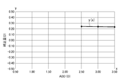
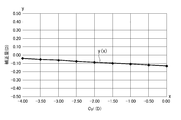
- the graph which shows the relationship between prescription addition degree ADD and correction amount The graph which shows the relationship between prescription addition degree ADD and correction amount.
- the graph which shows the relationship between prescription addition degree ADD and correction amount The graph which shows the relationship between prescription addition degree ADD and correction amount.
- the graph which shows the relationship between prescription addition degree ADD and correction amount The graph which shows the relationship between prescription addition degree ADD and correction amount.
- the graph which shows the relationship between prescription addition degree ADD and correction amount The graph which shows the relationship between prescription addition degree ADD and correction amount.
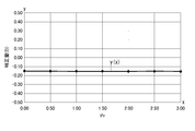
- the graph which shows the relationship between prescription addition degree ADD and correction amount The graph which shows the relationship between prescription addition degree ADD and correction amount. The graph which shows the relationship between prescription addition degree ADD and correction amount. The graph which shows the relationship between prescription addition degree ADD and correction amount. The graph which shows the relationship between astigmatism power Cyl and correction amount. The graph which shows the relationship between astigmatism power Cyl and correction amount. The graph which shows the relationship between astigmatism power Cyl and correction amount. The graph which shows the relationship between astigmatism power Cyl and correction amount. The graph which shows the relationship between astigmatism power Cyl and correction amount. The graph which shows the relationship between astigmatism power Cyl and correction amount. The graph which shows the relationship between astigmatism power Cyl and correction amount. The graph which shows the relationship between astigmatism power Cyl and correction amount. The graph which shows the relationship between astigmatism power Cyl and correction amount. The graph which shows the relationship between astigmatism power Cyl and correction amount. The graph which shows the relationship between astigmatism
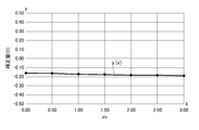
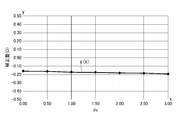
- the graph which shows the relationship between prism refractive power Pr and correction amount The graph which shows the relationship between prism refractive power Pr and correction amount. The graph which shows the relationship between prism refractive power Pr and correction amount. The graph which shows the relationship between prism refractive power Pr and correction amount. The graph which shows the relationship between prism refractive power Pr and correction amount. The graph which shows the relationship between prism refractive power Pr and correction amount. The graph which shows the relationship between prism refractive power Pr and correction amount. The graph which shows the relationship between prism refractive power Pr and correction amount. The graph which shows the relationship between prism refractive power Pr and correction amount. The surface refractive power distribution map of the first model.
- the principal power of 2nd Embodiment of this invention is shown, and the surface refractive power distribution map after the determination process.
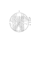
- FIG. 1A shows the front of the progressive-power lens.
- the progressive addition lens 1 includes a first region 1A that provides a first refractive power D1, a second region 1B that provides a second refractive power D2, a first region 1A, and a second region.
- the intermediate region 1C disposed between 1B and the side regions 1D disposed on both sides of the intermediate region 1C.
- the first area 1A is an area for distance vision
- the second area 1B is an area for near vision.
- the intermediate region 1C is a progressive region where the addition power continuously changes.
- the main meridian C is the position on the lens where the line of sight passes most frequently when performing near vision from far vision (moving from the upper side of the lens to the lower side) while wearing a progressive power lens. It is a line along.
- the eyeball side is a progressive surface and the object side is a spherical surface.
- a progressive start point PS is set at a position on the main meridian C and close to the first area 1A of the intermediate area 1C, and a progressive end point PE is set at a position close to the second area 1B.
- the main meridian C corresponds to the first region 1A, the line portion C1 set on the Y axis along the top and bottom, and the second region 1B corresponds to the second region 1B and is separated from the Y axis by the dimension I in the X axis direction, and the Y axis And a line part C3 corresponding to the intermediate area 1C and connecting the progressive start point PS and the progressive end point PE.
- a first measurement reference point P1 for measuring the magnitude of the first refractive power imparted in the first region 1A is set in the first region 1A.
- the first measurement reference point P1 is set on the main meridian and in the vicinity above the progressive start point PS.
- the first measurement reference point P1 may be located at the center of a first refractive power measurement reference circle (not shown), and the progressive start point PS may coincide with the arc portion of the first refractive power measurement reference circle.
- a second measurement reference point P2 for measuring the magnitude of the second refractive power imparted in the second region 1B is set in the second region 1B.
- the second measurement reference point P2 is set on the main meridian C and near the progressive end point PE.
- the second measurement reference point P2 may be positioned at the center of the first refractive power measurement reference circle (not shown), and the progressive end point PE may coincide with the arc portion of the first refractive power measurement reference circle.
- a fitting point FP is set at a position between the progressive start point PS and the progressive end point PE and along the extended line of the line portion C1 of the main meridian C.
- the extension line is a region located in the intermediate region 1C of the Y axis.
- the fitting point FP is set on the first area 1A side from the origin O, but may be coincident with the origin O, or may be set on the second area 1B side from the origin O. Good.
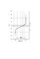
- the refractive power at the position on the main meridian C is shown.
- the refractive power of the line C1 in the main meridian C is the first refractive power D1 diopter from the first region 1A to the progressive start point PS, and the progressive end from the progressive start point PS of the line C3. It increases from D1 diopter to D2 diopter over the point PE, and remains D2 diopter from the progressive end point PE of the line part C2 to the lower part of the second region 1B.
- the addition at the fitting point FP is set as the target addition FAD.
- the target addition FAD is set in relation to a desired value regardless of the size of the prescription addition ADD.
- the desired value is set according to the target distance to the target position that the wearer wants to clearly see.
- the target addition FAD is (1 / d).
- the average gradient M of the addition between the progressive start point PS and the fitting point FP is set to be different from the average gradient N of the addition between the fitting point FP and the progressive end point PE.
- FIG. 2 shows an outline of the progressive-power lens designing apparatus 10 according to the first embodiment.
- the design apparatus 10 includes a simulation apparatus 20 and a computer 30.
- the simulation apparatus 20 performs a visual simulation assuming a spectacle wearing state on a first model (not shown) designed by setting a target addition FAD corresponding to the target distance d at the fitting point FP.
- a known ray tracing method is used.
- the light ray incident on the objective side surface of the lens is used to calculate the route along which the light ray comes out from the eyeball side surface of the lens and is collected.
- the ray tracing method is used.
- the simulation value SDD of the addition at the fitting point FP of the first model is calculated.
- the simulation device 20 has an input device (not shown) for inputting parameters and lens information other than the parameters.
- the parameters include objective addition FAD, prescription addition ADD, spherical power Sph of first region 1A to which first refractive power D1 is applied, astigmatism power Cyl, astigmatism axis direction Ax, prism refractive power Pr, prism base.
- the lens information includes the refractive index n of the lens, the fitting point FP, the progressive start point PS, the progressive end point PE, the first measurement reference point P1, and the second measurement.
- the visual simulation is performed a plurality of times by selecting a predetermined parameter and changing the value of the selected parameter.
- the computer 30 designs a progressive-power lens based on the result obtained by the simulation apparatus 20, and includes a processing unit 40 and an input unit 50.
- the input unit 50 inputs various pieces of information on the progressive-power lens to be designed, and examples of the input means include a keyboard and other input means in a personal computer.
- the input data input through the input unit 50 includes the target addition FAD, the prescription addition ADD, the spherical power Sph of the first region 1A to which the first refractive power D1 is applied, the astigmatic power Cyl, the astigmatic axis direction Ax, and the prism refractive power.
- Pr prism base direction PBE, convex curve ABC, lens center thickness CT, and lens information includes the refractive index n of the lens, the fitting point FP, the progressive start point PS, the progressive end point PE, and the first measurement reference point P1. And the position of the second measurement reference point P2, and other information required for lens design.
- the processing unit 40 includes an information acquisition unit 41, a calculation unit 42, a storage unit 43, a control unit 44, and a design unit 45.
- the information acquisition unit 41 acquires the addition simulation value SDD at the fitting point FP output from the simulation apparatus 20 and the parameter value changed in the simulation.
- the calculation unit 42 sets the difference between the addition simulation value SDD at the fitting point FP and the target addition FAD input at the input unit 50 as a correction amount CDD for each simulation.
- the storage unit 43 is based on the result calculated by the correction amount calculation unit 421, based on the correction amount storage unit 431 that stores the relationship between the parameter and the correction amount CDD, and the result calculated by the relational expression calculation unit 422. , A relational expression storage unit 432 that stores the relationship between parameters and relational expressions, and a basic information database 433.
- the basic information database 433 stores, for example, the position of the progressive start point PS, the position of the progressive end point PE, the position of the fitting point FP, and other basic information necessary for designing the lens.
- the control unit 44 collates the lens information for actual design input from the input unit 50 with the information stored in the storage unit 43 to obtain a correction amount CDD for designing the second model.
- the design unit 45 designs the second model (not shown) by adding the correction amount CDD obtained by the control unit 44 to the target addition FAD set by the first model.
- the designed second model is displayed on a display (not shown) or printed by a printing device (not shown).
- the fitting point FP is set to the origin O of the Y axis (see FIG. 1A).
- the target addition FAD is 1.00 diopter (D)
- Table 1 shows that when the spherical power Sph is ⁇ 8.00 diopter (D) and the prescription addition ADD is 2.50 diopter (D) (S1), and 3.00 diopter (D) (S2 ), The simulation value SDD and the correction amount CDD in the case of 3.50 diopter (D) (S3) are shown.
- the simulation value SDD is the magnitude of addition at a position corresponding to the fitting point FP on the main meridian.
- the simulation value SDD and the correction amount CDD are displayed by rounding off the decimal point 3 or less. The same applies to the following examples. Table 1 shows the necessary parameters for obtaining the simulation value SDD.
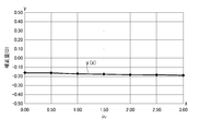
- a relational expression between the prescription addition ADD and the correction amount CDD can be obtained as an approximate expression of a polynomial. That is, if there are a plurality of points indicating the correspondence relationship between the prescription addition degree ADD and the correction amount CDD, the relational expression can be obtained by analogizing the locus of these points.
- the relational expression y (x) and the calculation result are shown in FIG.
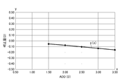
- Table 2 shows a case where the spherical power Sph is ⁇ 4.00 dioptre (D) and the prescription addition ADD is 2.50 dioptre (D) as an example of changing the prescription addition ADD (S4). , 3.00 diopter (D) (S5), and 3.50 diopter (D) (S3) simulation values SDD and correction amount CDD are shown. Table 2 shows the parameters necessary for obtaining the simulation value SDD.
- FIG. 4 shows the relational expression y (x) and the calculation result.
- Table 3 shows that when the spherical power Sph is 0.00 diopter (D) and the prescription addition ADD is 2.50 diopter (D) (S7), and 3.00 dioptre (D) (S8). , 3.50 diopter (D) (S9) simulation value SDD and correction amount CDD are shown. It should be noted that the parameters necessary for obtaining the simulation value SDD are shown in Table 3.
- Table 4 shows that when the spherical power Sph is 4.00 diopter (D) and the prescription addition ADD is 2.50 diopter (D) (S10), and 3.00 dioptre (D) (S11). , 3.50 diopter (D) (S12) simulation value SDD and correction amount CDD are shown. Table 4 shows the parameters required for obtaining the simulation value SDD.
- Table 5 shows that when the spherical power Sph is 6.00 diopter (D) and the prescription addition ADD is 2.50 diopter (D) (S13), and 3.00 diopter (D) (S14). , 3.50 diopter (D) (S15) simulation value SDD and correction amount CDD are shown. Table 5 shows necessary parameters for obtaining the simulation value SDD.
- FIG. 7 shows the relational expression y (x) and the calculation result.
- the target addition FAD is 0.50 diopter (D)
- the change of the correction amount CDD when the prescription addition ADD is changed with respect to the representative spherical power Sph of the first refractive power D1 is S16.
- Table 6 shows that when the spherical power Sph is ⁇ 8.00 dioptre (D) and the prescription addition ADD is 1.50 diopter (D) (S16), and 2.0 dioptre (D) (S17). ), 2.50 diopter (D) (S18), 3.00 diopter (D) (S19), 3.50 diopter (D) (S20) simulation value SDD and correction amount CDD is shown. Further, parameters required for obtaining the simulation value SDD are shown in Table 6.
- Table 7 shows that the spherical power Sph is ⁇ 4.00 diopter (D), the prescription addition ADD is 1.50 diopter (D) (S21), and 2.00 diopter (D) (S22). ), 2.50 diopter (D) (S23), 3.00 diopter (D) (S24), 3.50 diopter (D) (S25) simulation value SDD and correction amount CDD is shown. It should be noted that necessary parameters for obtaining the simulation value SDD are shown in Table 7.
- FIG. 9 shows the relational expression y (x) and the calculation result.
- Table 8 shows that when the spherical power Sph is 0.00 diopter (D) and the prescription addition ADD is 1.50 diopter (D) (S26), and 2.00 diopter (D) (S27). , 2.50 diopter (D) (S28), 3.00 diopter (D) (S29), 3.50 diopter (D) (S30) simulation value SDD and correction amount CDD It is shown. Table 8 shows necessary parameters for obtaining the simulation value SDD.
- Table 9 shows that when the spherical power Sph is 4.00 diopter (D) and the prescription addition ADD is 1.50 diopter (D) (S31), and 2.00 diopter (D) (S32). , 2.50 diopter (D) (S33), 3.00 diopter (D) (S34), 3.50 diopter (D) (S35) simulation value SDD and correction amount CDD It is shown. In addition, Table 9 shows parameters necessary for obtaining the simulation value SDD.
- FIG. 11 shows the relational expression y (x) and the calculation result.
- Table 10 shows that when the spherical power Sph is 6.00 diopters (D) and the prescription addition ADD is 1.50 diopters (D) (S36), and 2.00 diopters (D) (S37). , 2.50 diopter (D) (S38), 3.00 diopter (D) (S39), 3.50 diopter (D) (S40) simulation value SDD and correction amount CDD It is shown. Table 10 shows the parameters necessary for obtaining the simulation value SDD.
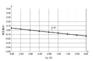
- Table 11 shows that the astigmatic power Cyl is 0.00 diopter (D) (S41), -0.50 diopter (D) (S42), and -1.00 diopter (D) ( S43), -1.50 diopter (D) (S44), -2.00 diopter (D) (S45), -2.50 diopter (D) (S46), -3 Simulation value SDD and correction amount CDD when .00 diopter (D) is set (S47), -3.50 diopter (D) is set (S48), and -4.00 diopter (D) is set (S49). It is shown.
- parameters required for obtaining the simulation value SDD are shown in Table 11.
- Table 12 shows that when the astigmatism axis direction Ax is 45 ° and the astigmatism power Cyl is 0.00 diopter (D) (S50), -0.50 dioptre (D) (S51), -1. 00 diopter (D) (S52), -1.50 diopter (D) (S53), -2.00 diopter (D) (S54), -2.50 diopter (D) (S55), -3.00 diopter (D) (S56), -3.50 diopter (D) (S57), and -4.00 diopter (D) (S58). ) Shows a simulation value SDD and a correction amount CDD. In addition, Table 12 shows necessary parameters for obtaining the simulation value SDD.
- FIG. 14 shows the relational expression y (x) and the calculation result.
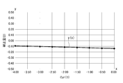
- Table 13 shows that when the astigmatic axis direction Ax is 90 ° and the astigmatism power Cyl is 0.00 diopter (D) (S59), -0.50 dioptre (D) (S60), -1. 00 diopter (D) (S61), -1.50 diopter (D) (S62), -2.00 diopter (D) (S63), -2.50 diopter (D) (S64), -3.00 diopter (D) (S65), -3.50 diopter (D) (S66), and -4.00 diopter (D) (S67). ) Shows a simulation value SDD and a correction amount CDD. In addition, parameters required for obtaining the simulation value SDD are shown in Table 13.
- FIG. 15 shows the relational expression y (x) and the calculation result.
- Table 14 shows that when the astigmatic axis direction Ax is 135 ° and the astigmatism power Cyl is 0.00 diopter (D) (S68), -0.50 dioptre (D) (S69), -1. 00 diopter (D) (S70), -1.50 diopter (D) (S71), -2.00 diopter (D) (S72), -2.50 diopter (D) (S73), -3.00 diopter (D) (S74), -3.50 diopter (D) (S75), and -4.00 diopter (D) (S76). ) Shows a simulation value SDD and a correction amount CDD. Further, parameters required for obtaining the simulation value SDD are shown in Table 14.
- Table 16 shows that when the astigmatic axis direction Ax is 45 ° and the astigmatism power Cyl is 0.00 diopter (D) (S86), -0.50 dioptre (D) (S87), -1. 00 diopter (D) (S88), -1.50 diopter (D) (S89), -2.00 diopter (D) (S90), -2.50 diopter (D) (S91), -3.00 diopter (D) (S92), -3.50 diopter (D) (S93), -4.00 diopter (D) (S94) ) Shows a simulation value SDD and a correction amount CDD. In addition, parameters required for obtaining the simulation value SDD are shown in Table 16.
- Table 17 shows that when the astigmatism axis direction Ax is 90 ° and the astigmatism power Cyl is 0.00 diopter (D) (S95), -0.50 dioptre (D) (S96), -1. 00 diopter (D) (S97), -1.50 diopter (D) (S98), -2.00 diopter (D) (S99), -2.50 diopter (D) (S100), -3.00 diopter (D) (S101), -3.50 diopter (D) (S102), -4.00 diopter (D) (S103) ) Shows a simulation value SDD and a correction amount CDD. In addition, parameters required for obtaining the simulation value SDD are shown in Table 17.
- Table 18 shows the cases where the astigmatic axis direction Ax is 135 ° and the astigmatic power Cyl is 0.00 diopter (D) (S104), -0.50 dioptre (D) (S105), and -1. 00 diopter (D) (S106), -1.50 diopter (D) (S107), -2.00 diopter (D) (S108), -2.50 diopter (D) (S109), -3.00 diopter (D) (S110), -3.50 diopter (D) (S111), -4.00 diopter (D) (S112) ) Shows a simulation value SDD and a correction amount CDD. In addition, parameters required for obtaining the simulation value SDD are shown in Table 18.
- the target addition FAD is 1.00 diopter (D)
- the change in the correction amount CDD when the prism refractive power Pr is changed with respect to the typical prism base direction PBE is based on S113 to S140.
- Table 19 shows that the prism base direction PBE is 0 ° and the prism refractive power Pr is 0.00 diopter (D) (S113), 0.50 diopter (D) (S114), and 1.00.
- diopter (D) (S115) 1.50 diopter (D) (S116), 2.00 diopter (D) (S117), 2.50 diopter (D) ( S118)
- the simulation value SDD and the correction amount CDD in the case of 3.00 diopter (D) (S119) are shown.
- parameters required for obtaining the simulation value SDD are shown in Table 19.
- FIG. 21 shows the relational expression y (x) and the calculation result.
- Table 20 shows that the prism base direction PBE is 90 ° and the prism refractive power Pr is 0.00 diopter (D) (S120), 0.50 diopter (D) (S121), 1.00.
- diopter (D) (S122), 1.50 diopter (D) (S123), 2.00 diopter (D) (S124), 2.50 diopter (D) ( S125) the simulation value SDD and the correction amount CDD in the case of 3.00 diopter (D) (S126) are shown.
- parameters required for obtaining the simulation value SDD are shown in Table 20.
- Table 21 shows that the prism base direction PBE is 180 °, and the prism refractive power Pr is 0.00 diopter (D) (S127), 0.50 diopter (D) (S128), 1.00.
- diopter (D) S129
- 1.50 diopter D
- S130 1.50 diopter
- D S131
- 2.50 diopter D
- SDD simulation value
- parameters required for obtaining the simulation value SDD are shown in Table 23.
- Table 22 shows that the prism base direction PBE is 270 ° and the prism refractive power Pr is 0.00 diopter (D) (S134), 0.50 diopter (D) (S135), 1.00.
- diopter (D) (S136), 1.50 diopter (D) (S137), 2.00 diopter (D) (S138), 2.50 diopter (D) ( S139) the simulation value SDD and the correction amount CDD in the case of 3.00 diopter (D) (S140) are shown.
- Table 22 shows necessary parameters for obtaining the simulation value SDD.
- the target addition FAD is 0.50 diopter (D)
- the change in the correction amount CDD when the prism refractive power Pr is changed with respect to the typical prism base direction PBE is based on S141 to S168.
- Table 23 shows that the prism base direction PBE is 0 ° and the prism refractive power Pr is 0.00 diopter (D) (S141), 0.50 diopter (D) (S142), and 1.00.
- diopter (D) (S143) 1.50 diopter (D) (S144), 2.00 diopter (D) (S145), 2.50 diopter (D) ( S146)
- the simulation value SDD and the correction amount CDD in the case of 3.00 diopter (D) (S147) are shown.
- parameters required for obtaining the simulation value SDD are shown in Table 23.
- Table 24 shows that the prism base direction PBE is 90 ° and the prism refractive power Pr is 0.00 diopter (D) (S148), 0.50 diopter (D) (S149), and 1.00.
- diopter (D) (S150) 1.50 diopter (D) (S151), 2.00 diopter (D) (S152), 2.50 diopter (D) ( S153)
- the simulation value SDD and the correction amount CDD in the case of 3.00 diopter (D) (S154) are shown.
- Table 24 shows necessary parameters for obtaining the simulation value SDD.
- Table 25 shows that the prism base direction PBE is 180 ° and the prism refractive power Pr is 0.00 diopter (D) (S155), 0.50 diopter (D) (S156), 1.00.
- diopter (D) (S157), 1.50 diopter (D) (S158), 2.00 diopter (D) (S159), 2.50 diopter (D) ( S160) the simulation value SDD and the correction amount CDD in the case of 3.00 diopter (D) (S161) are shown.
- Table 25 shows necessary parameters for obtaining the simulation value SDD.
- Table 26 shows that the prism base direction PBE is 270 ° and the prism refractive power Pr is 0.00 diopter (D) (S162), 0.50 diopter (D) (S163), and 1.00.
- diopter (D) (S164) 1.50 diopter (D) (S165), 2.00 diopter (D) (S166), 2.50 diopter (D) ( S167)
- simulation value SDD and correction amount CDD in the case of 3.00 diopter (D) (S168) are shown. Further, parameters required for obtaining the simulation value SDD are shown in Table 26.
- the progressive addition lens is designed with a prescription addition ADD of 3.00 diopters (D).
- a fitting point FP is set at a position corresponding to the main meridian (the origin O of the Y axis in FIG. 1A), and the target addition FAD is set as 0.5 diopter (D).
- the surface refractive power distribution on the progressive surface (concave surface) side of the first model is shown in FIG. 29A.
- a region E1 has a refractive power of 8.00 to 8.25 diopters (D)
- a region E2 has a refractive power of 8.25 to 8.50 diopters (D)
- a region E3 has a refractive power of 8.50. ⁇ 8.75 diopters (D).
- the refractive power at the position corresponding to the fitting point FP on the main meridian is a value obtained by subtracting the target addition FAD from the first refractive power D1. 8.50 diopters (D).
- FIG. 29B the relationship between the refractive power of the eyeball side surface of the lens and the position of the main meridian is shown.
- the refractive power changes from the progressive start point PS to the progressive end point PE, and the refractive power at the position corresponding to the fitting point FP in the main meridian is 8.5 diopters (D).
- FIGS. 30A and 30B show the results of visual simulation performed on the first model shown in FIGS. 29A and 29B.
- 30A and 30B differ from FIGS. 29A and 29B in that they are viewed.
- a region F1 has a refractive power of ⁇ 7.50 to ⁇ 7.25 diopter (D)
- a region F2 has a refractive power of ⁇ 7.50 to ⁇ 7.75 diopter (D).
- the fitting point FP is in the area F2.
- FIG. 30B the relationship between refractive power and the position of the main meridian is shown.
- the simulation value of refractive power is ⁇ 7.70 diopter (D) at the position corresponding to the fitting point FP of the main meridian. This corresponds to 0.20 diopter (D) of the simulation value SDD of the addition at the position corresponding to the fitting point FP of the main meridian.
- the simulation result from the simulation apparatus 20 is acquired by the information acquisition unit 41 of the computer 30.
- the calculation unit 42 calculates a correction amount CDD from the simulation result acquired by the information acquisition unit 41 and information on the progressive power lens to be designed input through the input unit 50, and obtains a relational expression from the correction amount CDD.
- the refractive power simulation value is ⁇ 7.70 diopter (D). This translates into 0.30 diopter (D) when converted to the addition simulation value SDD, which is deficient by 0.20 diopter (D). Therefore, the correction amount CDD is 0.20 diopter (D), which is an insufficient value.
- the target addition FAD of the progressive power lens to be designed is set to 0.50 diopter (D), which is a value set in the visual simulation, but the target addition FAD of the progressive power lens to be designed is set at the time of simulation. If the value is not set, the correction amount CDD is calculated based on the relational expression.
- the correction amount CDD obtained by the control unit 44 is added to the target addition FAD and set again at a position corresponding to the fitting point FP on the main meridian to design a second model. For example, as shown in FIGS. 31A and 31B, when designing the first model, correction is made for the refractive power of 8.50 diopters (D) set as the addition on the main meridian corresponding to the fitting point FP.
- a value obtained by adding 0.2 diopter (D) of the amount CDD (8.70 diopter (D)) is reset.
- a visual simulation assuming a spectacle wearing state is performed on the first model designed by setting a target addition FAD of a desired value at a position corresponding to the fitting point FP on the main meridian, and obtained by visual simulation.
- the correction amount CDD for correcting the difference between the simulation value SDD of the addition at the position corresponding to the fitting point FP on the main meridian and the target addition FAD is calculated, and the correction amount CDD obtained by the calculation is used as the target addition power.
- the second model is designed by setting again as the addition added to the FAD, the visual simulation assuming the actual wearing state is performed on the first model, so in the final second model, The target addition FAD at the fitting point FP is less likely to deviate from the addition at the time of wearing.
- the factors that cause the added power to deviate from the set target power FAD are the size of the target power FAD, the prescription power ADD, the spherical power Sph, the astigmatic power Cyl, the astigmatic axis.
- a correction amount is obtained for each data related to these factors, so that the deviation of the target addition FAD at the fitting point from the addition during wearing is determined. Can be very small.
- FIGS. 32A and 32B a second embodiment of the present invention will be described based on FIGS. 32A and 32B.
- the same components as those in the first embodiment are denoted by the same reference numerals and the description thereof is omitted.
- the second embodiment performs the determination process after performing the simulation process, the correction amount calculation process, and the design process.
- the computer 30 of 1st Embodiment may be used from a simulation process to a design process, and another apparatus may be used.
- [Judgment process] A simulation assuming the spectacle wearing state is performed again on the second model designed in the design process. The simulation to be performed again is performed in the same process as the simulation process of the first embodiment. The results obtained in the simulation process performed again are shown in FIGS. 32A and 32B.
- the fitting point FP is at the boundary portion ( ⁇ 7.50 diopter (D)) between the region F1 and the region F2.
- the simulation value of refractive power is ⁇ 7.50 diopter (D) at the position of the main meridian where the fitting point FP is set (origin 0).
- the re-simulation value ( ⁇ 7.50 diopter (D)) obtained in the re-executed simulation process matches the refractive power ( ⁇ 7.50 diopter (D)) set as the target addition FAD. It will be. This completes the design process.
- the determination process when it is determined that the re-simulation value does not match the desired value based on the target addition FAD, the design process is performed again, and the determination process is performed again.
- the simulation process assuming the spectacle wearing state is performed again on the second model designed in the design process, and the re-simulation value obtained in the simulation process and the target addition FAD are calculated. Since it is determined whether or not the desired value is based on this, it is possible to confirm whether or not the correction of the progressive-power lens after the design is correctly performed.
- the present invention is not limited to the above-described embodiments, and modifications, improvements, and the like within the scope that can achieve the object of the present invention are included in the present invention.
- the main meridian C is set on the Y axis along the top and bottom corresponding to the first region 1A.
- the main meridian C is linearly formed along the Y axis over the first region 1A, the intermediate region 1C, and the second region 1B. You may do it.
- the line segment along the top and bottom of the main meridian is not limited to the one set on the Y axis, and may be separated from the Y axis in the X axis direction and parallel to the Y axis.
- the progressive addition lens 1 designed in each embodiment has a progressive surface on the eyeball side and a spherical surface on the object side.
- both the eyeball side and the object side are designed as progressive surfaces. It can also be applied to things.
- a relational expression indicating the relationship between the correction amount and the parameter obtained for each simulation executed a plurality of times is obtained by the calculation process, and the design process is performed. It is also possible to set the addition power at the position corresponding to the fitting point FP on the main meridian based on the relational expression obtained in the calculation process. In the present invention, it is not always necessary to obtain the relational expression.
- SYMBOLS 1 ... Progressive-power lens, 10 ... Progressive-power lens design apparatus, 1A ... 1st area
Abstract
La présente invention concerne une simulation de vision, sur l'hypothèse que des lunettes sont portées, qui est exécutée à l'aide d'un premier modèle, celui-ci étant conçu par l'établissement d'une puissance supplémentaire prévue (FAD) d'une valeur souhaitable à la position correspondant à un point d'ajustement (FP) sur un méridien principal. Une quantité de correction (CDD) est calculée dans le but de corriger la différence entre une valeur de simulation (SDD) obtenue pour la puissance supplémentaire à la position correspondant au point d'ajustement (FP) sur le méridien principal au moyen de la simulation de vision et de la puissance supplémentaire prévue. Un second modèle est conçu en remplaçant la puissance supplémentaire par une valeur obtenue par l'ajout de la quantité de correction calculée (CDD) à la puissance supplémentaire prévue (FAD)
Priority Applications (4)
| Application Number | Priority Date | Filing Date | Title |
|---|---|---|---|
| EP16800096.6A EP3306499A4 (fr) | 2015-05-26 | 2016-05-26 | Procédé et dispositif de conception destinés à une lentille à puissance progressive |
| JP2017520804A JP6496019B2 (ja) | 2015-05-26 | 2016-05-26 | 累進屈折力レンズの設計方法及び設計装置 |
| US15/576,266 US10545354B2 (en) | 2015-05-26 | 2016-05-26 | Designing method and designing device for progressive power lens |
| CN201680030205.1A CN107615280B (zh) | 2015-05-26 | 2016-05-26 | 渐进屈光力镜片的设计方法及设计装置 |
Applications Claiming Priority (2)
| Application Number | Priority Date | Filing Date | Title |
|---|---|---|---|
| JP2015-106887 | 2015-05-26 | ||
| JP2015106887 | 2015-05-26 |
Publications (1)
| Publication Number | Publication Date |
|---|---|
| WO2016190392A1 true WO2016190392A1 (fr) | 2016-12-01 |
Family
ID=57393916
Family Applications (1)
| Application Number | Title | Priority Date | Filing Date |
|---|---|---|---|
| PCT/JP2016/065598 WO2016190392A1 (fr) | 2015-05-26 | 2016-05-26 | Procédé et dispositif de conception destinés à une lentille à puissance progressive |
Country Status (5)
| Country | Link |
|---|---|
| US (1) | US10545354B2 (fr) |
| EP (1) | EP3306499A4 (fr) |
| JP (1) | JP6496019B2 (fr) |
| CN (1) | CN107615280B (fr) |
| WO (1) | WO2016190392A1 (fr) |
Cited By (1)
| Publication number | Priority date | Publication date | Assignee | Title |
|---|---|---|---|---|
| CN111358421A (zh) * | 2020-03-16 | 2020-07-03 | 深圳盛达同泽科技有限公司 | 屈光图形生成方法、装置及计算机可读存储介质 |
Families Citing this family (9)
| Publication number | Priority date | Publication date | Assignee | Title |
|---|---|---|---|---|
| WO2016190391A1 (fr) * | 2015-05-26 | 2016-12-01 | ホヤ レンズ タイランド リミテッド | Procédé de conception de lentille à puissance de réfraction progressive et ensemble de lentilles |
| US11175518B2 (en) | 2018-05-20 | 2021-11-16 | Neurolens, Inc. | Head-mounted progressive lens simulator |
| US10783700B2 (en) | 2018-05-20 | 2020-09-22 | Neurolens, Inc. | Progressive lens simulator with an axial power-distance simulator |
| US11559197B2 (en) | 2019-03-06 | 2023-01-24 | Neurolens, Inc. | Method of operating a progressive lens simulator with an axial power-distance simulator |
| US11202563B2 (en) | 2019-03-07 | 2021-12-21 | Neurolens, Inc. | Guided lens design exploration system for a progressive lens simulator |
| US11259699B2 (en) | 2019-03-07 | 2022-03-01 | Neurolens, Inc. | Integrated progressive lens simulator |
| US11288416B2 (en) | 2019-03-07 | 2022-03-29 | Neurolens, Inc. | Deep learning method for a progressive lens simulator with an artificial intelligence engine |
| US11259697B2 (en) | 2019-03-07 | 2022-03-01 | Neurolens, Inc. | Guided lens design exploration method for a progressive lens simulator |
| US11241151B2 (en) | 2019-03-07 | 2022-02-08 | Neurolens, Inc. | Central supervision station system for Progressive Lens Simulators |
Citations (3)
| Publication number | Priority date | Publication date | Assignee | Title |
|---|---|---|---|---|
| JP2012022288A (ja) * | 2010-03-10 | 2012-02-02 | Seiko Epson Corp | 累進屈折力レンズの設計方法、累進屈折力レンズ設計システム、および累進屈折力レンズ |
| JP2012185424A (ja) * | 2011-03-08 | 2012-09-27 | Seiko Epson Corp | 累進屈折力レンズの設計方法 |
| JP2013217948A (ja) * | 2012-03-12 | 2013-10-24 | Nikon-Essilor Co Ltd | 眼鏡レンズ、眼鏡レンズの製造方法及び眼鏡レンズの設計方法 |
Family Cites Families (8)
| Publication number | Priority date | Publication date | Assignee | Title |
|---|---|---|---|---|
| JP3853849B2 (ja) | 1993-12-09 | 2006-12-06 | セイコーエプソン株式会社 | 眼鏡レンズ |
| JP3881449B2 (ja) * | 1998-04-17 | 2007-02-14 | ペンタックス株式会社 | 累進多焦点レンズの加工方法 |
| CN1815299B (zh) * | 2005-02-04 | 2010-06-02 | 精工爱普生株式会社 | 组合眼镜镜片、辅助镜片和组合眼镜镜片的磨边加工方法 |
| JP4400549B2 (ja) * | 2005-02-04 | 2010-01-20 | セイコーエプソン株式会社 | 組み合わせ眼鏡レンズ及び組み合わせ眼鏡レンズの玉型加工方法 |
| DE102010049168A1 (de) | 2010-10-21 | 2012-04-26 | Rodenstock Gmbh | Verordnungs- und individualisierungsabhängige Modifikation des temporalen peripheren Sollastigmatismus und Anpassung der Objektabstandsfunktion an veränderte Objektabstände für die Nähe und/oder die Ferne |
| JP2012103312A (ja) * | 2010-11-08 | 2012-05-31 | Seiko Epson Corp | 累進屈折力レンズ及びその設計方法 |
| JP6242013B2 (ja) * | 2012-03-23 | 2017-12-06 | Hoya株式会社 | 眼鏡レンズ、並びに眼鏡レンズの設計方法、製造方法及び製造システム |
| FR2996316B1 (fr) | 2012-09-28 | 2015-09-18 | Thomas Sinclair Laboratoires | Lentille ophtalmique progressive pour patient souffrant de deficience visuelle |
-
2016
- 2016-05-26 EP EP16800096.6A patent/EP3306499A4/fr active Pending
- 2016-05-26 WO PCT/JP2016/065598 patent/WO2016190392A1/fr active Application Filing
- 2016-05-26 CN CN201680030205.1A patent/CN107615280B/zh active Active
- 2016-05-26 JP JP2017520804A patent/JP6496019B2/ja active Active
- 2016-05-26 US US15/576,266 patent/US10545354B2/en active Active
Patent Citations (3)
| Publication number | Priority date | Publication date | Assignee | Title |
|---|---|---|---|---|
| JP2012022288A (ja) * | 2010-03-10 | 2012-02-02 | Seiko Epson Corp | 累進屈折力レンズの設計方法、累進屈折力レンズ設計システム、および累進屈折力レンズ |
| JP2012185424A (ja) * | 2011-03-08 | 2012-09-27 | Seiko Epson Corp | 累進屈折力レンズの設計方法 |
| JP2013217948A (ja) * | 2012-03-12 | 2013-10-24 | Nikon-Essilor Co Ltd | 眼鏡レンズ、眼鏡レンズの製造方法及び眼鏡レンズの設計方法 |
Non-Patent Citations (1)
| Title |
|---|
| See also references of EP3306499A4 * |
Cited By (1)
| Publication number | Priority date | Publication date | Assignee | Title |
|---|---|---|---|---|
| CN111358421A (zh) * | 2020-03-16 | 2020-07-03 | 深圳盛达同泽科技有限公司 | 屈光图形生成方法、装置及计算机可读存储介质 |
Also Published As
| Publication number | Publication date |
|---|---|
| EP3306499A4 (fr) | 2019-02-06 |
| JPWO2016190392A1 (ja) | 2018-03-22 |
| CN107615280A (zh) | 2018-01-19 |
| US20180149883A1 (en) | 2018-05-31 |
| JP6496019B2 (ja) | 2019-04-03 |
| CN107615280B (zh) | 2021-12-24 |
| EP3306499A1 (fr) | 2018-04-11 |
| US10545354B2 (en) | 2020-01-28 |
Similar Documents
| Publication | Publication Date | Title |
|---|---|---|
| JP6496019B2 (ja) | 累進屈折力レンズの設計方法及び設計装置 | |
| CN102439511B (zh) | 评估眼科镜片设计的光学特征的方法 | |
| EP2959339B1 (fr) | Méthode de production d'une paire de verres ophtalmiques progressifs | |
| US11415816B2 (en) | Contact lens | |
| EP2442171A2 (fr) | Verres de lunettes, lunettes et procédé de fabrication de verres de lunettes | |
| CN110431474A (zh) | 具有可变折光力的渐变眼镜片及其设计与生产方法 | |
| US10386652B2 (en) | Lens design method, lens manufacturing method, storage medium, and lens design system | |
| CN106716231B (zh) | 用于向配戴者提供定制的渐变眼镜眼科镜片的多焦点镜片供应系统 | |
| US20170299891A1 (en) | Progressive power lens and method of designing and manufacturing the same | |
| TWI663444B (zh) | 在生產眼鏡鏡片用於建立目標設計之方法及設備 | |
| WO2016068117A1 (fr) | Procédé de conception de lentille, procédé de fabrication de lentille, programme de conception de lentille et système de conception de lentille | |
| US20180307058A1 (en) | Computer implemented method of determining a base curve for a spectacle lens and method of manufacturing a spectacle lens | |
| JP2019045545A (ja) | バイフォーカルレンズ及びそのバイフォーカルレンズの製造方法 | |
| JP5057229B2 (ja) | 可変焦点レンズ | |
| KR20220019672A (ko) | 착용자에게 맞춰진 안과용 요소를 결정하는 방법 및 시스템 | |
| JP6416394B2 (ja) | 累進屈折力レンズの設計方法及びレンズセット | |
| JP6495864B2 (ja) | 眼鏡レンズ、眼鏡レンズの設計方法、眼鏡レンズの製造方法 | |
| CN105204181B (zh) | 渐进多焦点镜片 | |
| CN105074541A (zh) | 眼镜镜片及其制造方法以及镜片供给系统 | |
| JP2014215538A (ja) | 眼鏡レンズの設計方法、眼鏡レンズ設計装置、眼鏡レンズの製造方法、及び眼鏡レンズ製造システム | |
| ITBO20070816A1 (it) | Lente oftalmica multifocale progressiva e semilavorato per la realizzazione di una lente oftalmica multifocale progressiva |
Legal Events
| Date | Code | Title | Description |
|---|---|---|---|
| 121 | Ep: the epo has been informed by wipo that ep was designated in this application |
Ref document number: 16800096 Country of ref document: EP Kind code of ref document: A1 |
|
| WWE | Wipo information: entry into national phase |
Ref document number: 15576266 Country of ref document: US |
|
| ENP | Entry into the national phase |
Ref document number: 2017520804 Country of ref document: JP Kind code of ref document: A |
|
| NENP | Non-entry into the national phase |
Ref country code: DE |