WO2016190225A1 - 電極材料、その製造方法、および、それを用いた蓄電デバイス - Google Patents
電極材料、その製造方法、および、それを用いた蓄電デバイス Download PDFInfo
- Publication number
- WO2016190225A1 WO2016190225A1 PCT/JP2016/064937 JP2016064937W WO2016190225A1 WO 2016190225 A1 WO2016190225 A1 WO 2016190225A1 JP 2016064937 W JP2016064937 W JP 2016064937W WO 2016190225 A1 WO2016190225 A1 WO 2016190225A1
- Authority
- WO
- WIPO (PCT)
- Prior art keywords
- ionic liquid
- imide
- bis
- trifluoromethanesulfonyl
- electrode material
- Prior art date
- Legal status (The legal status is an assumption and is not a legal conclusion. Google has not performed a legal analysis and makes no representation as to the accuracy of the status listed.)
- Ceased
Links
Images








Classifications
-
- H—ELECTRICITY
- H01—ELECTRIC ELEMENTS
- H01G—CAPACITORS; CAPACITORS, RECTIFIERS, DETECTORS, SWITCHING DEVICES, LIGHT-SENSITIVE OR TEMPERATURE-SENSITIVE DEVICES OF THE ELECTROLYTIC TYPE
- H01G11/00—Hybrid capacitors, i.e. capacitors having different positive and negative electrodes; Electric double-layer [EDL] capacitors; Processes for the manufacture thereof or of parts thereof
- H01G11/22—Electrodes
- H01G11/24—Electrodes characterised by structural features of the materials making up or comprised in the electrodes, e.g. form, surface area or porosity; characterised by the structural features of powders or particles used therefor
-
- H—ELECTRICITY
- H01—ELECTRIC ELEMENTS
- H01G—CAPACITORS; CAPACITORS, RECTIFIERS, DETECTORS, SWITCHING DEVICES, LIGHT-SENSITIVE OR TEMPERATURE-SENSITIVE DEVICES OF THE ELECTROLYTIC TYPE
- H01G11/00—Hybrid capacitors, i.e. capacitors having different positive and negative electrodes; Electric double-layer [EDL] capacitors; Processes for the manufacture thereof or of parts thereof
- H01G11/22—Electrodes
- H01G11/30—Electrodes characterised by their material
- H01G11/32—Carbon-based
- H01G11/36—Nanostructures, e.g. nanofibres, nanotubes or fullerenes
-
- H—ELECTRICITY
- H01—ELECTRIC ELEMENTS
- H01G—CAPACITORS; CAPACITORS, RECTIFIERS, DETECTORS, SWITCHING DEVICES, LIGHT-SENSITIVE OR TEMPERATURE-SENSITIVE DEVICES OF THE ELECTROLYTIC TYPE
- H01G11/00—Hybrid capacitors, i.e. capacitors having different positive and negative electrodes; Electric double-layer [EDL] capacitors; Processes for the manufacture thereof or of parts thereof
- H01G11/54—Electrolytes
- H01G11/58—Liquid electrolytes
-
- H—ELECTRICITY
- H01—ELECTRIC ELEMENTS
- H01G—CAPACITORS; CAPACITORS, RECTIFIERS, DETECTORS, SWITCHING DEVICES, LIGHT-SENSITIVE OR TEMPERATURE-SENSITIVE DEVICES OF THE ELECTROLYTIC TYPE
- H01G11/00—Hybrid capacitors, i.e. capacitors having different positive and negative electrodes; Electric double-layer [EDL] capacitors; Processes for the manufacture thereof or of parts thereof
- H01G11/84—Processes for the manufacture of hybrid or EDL capacitors, or components thereof
- H01G11/86—Processes for the manufacture of hybrid or EDL capacitors, or components thereof specially adapted for electrodes
-
- H—ELECTRICITY
- H01—ELECTRIC ELEMENTS
- H01M—PROCESSES OR MEANS, e.g. BATTERIES, FOR THE DIRECT CONVERSION OF CHEMICAL ENERGY INTO ELECTRICAL ENERGY
- H01M10/00—Secondary cells; Manufacture thereof
- H01M10/05—Accumulators with non-aqueous electrolyte
- H01M10/052—Li-accumulators
-
- H—ELECTRICITY
- H01—ELECTRIC ELEMENTS
- H01M—PROCESSES OR MEANS, e.g. BATTERIES, FOR THE DIRECT CONVERSION OF CHEMICAL ENERGY INTO ELECTRICAL ENERGY
- H01M10/00—Secondary cells; Manufacture thereof
- H01M10/05—Accumulators with non-aqueous electrolyte
- H01M10/056—Accumulators with non-aqueous electrolyte characterised by the materials used as electrolytes, e.g. mixed inorganic/organic electrolytes
- H01M10/0564—Accumulators with non-aqueous electrolyte characterised by the materials used as electrolytes, e.g. mixed inorganic/organic electrolytes the electrolyte being constituted of organic materials only
- H01M10/0566—Liquid materials
- H01M10/0568—Liquid materials characterised by the solutes
-
- H—ELECTRICITY
- H01—ELECTRIC ELEMENTS
- H01M—PROCESSES OR MEANS, e.g. BATTERIES, FOR THE DIRECT CONVERSION OF CHEMICAL ENERGY INTO ELECTRICAL ENERGY
- H01M4/00—Electrodes
- H01M4/02—Electrodes composed of, or comprising, active material
- H01M4/36—Selection of substances as active materials, active masses, active liquids
-
- H—ELECTRICITY
- H01—ELECTRIC ELEMENTS
- H01M—PROCESSES OR MEANS, e.g. BATTERIES, FOR THE DIRECT CONVERSION OF CHEMICAL ENERGY INTO ELECTRICAL ENERGY
- H01M4/00—Electrodes
- H01M4/02—Electrodes composed of, or comprising, active material
- H01M4/36—Selection of substances as active materials, active masses, active liquids
- H01M4/58—Selection of substances as active materials, active masses, active liquids of inorganic compounds other than oxides or hydroxides, e.g. sulfides, selenides, tellurides, halogenides or LiCoFy; of polyanionic structures, e.g. phosphates, silicates or borates
- H01M4/583—Carbonaceous material, e.g. graphite-intercalation compounds or CFx
- H01M4/587—Carbonaceous material, e.g. graphite-intercalation compounds or CFx for inserting or intercalating light metals
-
- Y—GENERAL TAGGING OF NEW TECHNOLOGICAL DEVELOPMENTS; GENERAL TAGGING OF CROSS-SECTIONAL TECHNOLOGIES SPANNING OVER SEVERAL SECTIONS OF THE IPC; TECHNICAL SUBJECTS COVERED BY FORMER USPC CROSS-REFERENCE ART COLLECTIONS [XRACs] AND DIGESTS
- Y02—TECHNOLOGIES OR APPLICATIONS FOR MITIGATION OR ADAPTATION AGAINST CLIMATE CHANGE
- Y02E—REDUCTION OF GREENHOUSE GAS [GHG] EMISSIONS, RELATED TO ENERGY GENERATION, TRANSMISSION OR DISTRIBUTION
- Y02E60/00—Enabling technologies; Technologies with a potential or indirect contribution to GHG emissions mitigation
- Y02E60/10—Energy storage using batteries
Definitions
- the present invention relates to an electrode material using graphene oxide, a manufacturing method thereof, and an electricity storage device using the same.
- Non-Patent Document 1 N-butyl-n-methylpyrrolidinium bis (trifluoromethanesulfonyl) imide (PYR 14 TFSI) as an ionic liquid, acetonitrile, butylnitrile, benzonitrile, propylene carbonate as solvent molecules,
- PYR 14 TFSI N-butyl-n-methylpyrrolidinium bis (trifluoromethanesulfonyl) imide
- Non-Patent Document 2 there is a technique in which a mixture of an ionic liquid and a single-walled nanotube is used as an electrolyte (see, for example, Non-Patent Document 2).
- the conductivity can be improved by adding single-walled nanotubes to 1-ethyl-3-methylimidazolium tetrafluoroborate (EMIBF 4 ) as an ionic liquid.
- EMIBF 4 1-ethyl-3-methylimidazolium tetrafluoroborate
- Non-Patent Document 1 and Non-Patent Document 2 are aimed at improving the characteristics of ionic liquids for power storage devices, and attention has not been paid to electrode materials.
- An object of the present invention is to provide an electrode material that improves rate characteristics in an electricity storage device using an ionic liquid as an electrolyte, a manufacturing method thereof, and an electricity storage device using the electrode material.
- the electrode material including a laminate in which reduced graphene oxide is laminated according to the present invention includes an ionic liquid between the reduced graphene oxide, thereby achieving the above-described problem.
- the weight ratio of the ionic liquid to the reduced graphene oxide may be in the range of 0.01 to 1.00.
- the weight ratio of the ionic liquid to the reduced graphene oxide may be in the range of 0.02 to 0.60.
- the specific surface area of the laminate may be in the range of 350 m 2 / g to 500 m 2 / g.
- the specific surface area of the laminate may be 420 m 2 / g or more and 450 m 2 / g or less.
- the pore volume of the laminate may be in the range of 0.75 cc / g to 1.5 cc / g.
- the pore volume of the laminate may be in the range of 0.85 cc / g to 0.95 cc / g.
- the ionic liquids are 1-ethyl-3-methylimidazolium tetrafluoroborate (EMIMBF 4 ), 1-ethyl-3-methylimidazolium-bis (fluorosulfonyl) imide (EMIFSI), 1-ethyl-3-methylimidazole Rium-bis (trifluoromethanesulfonyl) imide (EMITFSI), 1-butyl-3-methylimidazolium-bis (trifluoromethanesulfonyl) imide (BMITSI), 1-hexyl-3-methylimidazolium tetrafluoroborate (HMIBF 4 ) , 1-hexyl-3-methylimidazolium - bis (trifluoromethanesulfonyl) imide (HMITFSI), 1-ethyl-3-methylimidazolium - fluorohydrocarbon oxygenate (EMI (FH) 2.3 F) , N, N Diethyl -N-
- the laminate may have mesopores having a diameter in the range of 2 nm to 6 nm and macropores having a diameter of 50 nm or more.
- the laminate may have a specific capacity in the range of 80 F / g or more and 140 F / g or less at a current density of 20 A / g.
- a method for producing an electrode material according to the present invention includes the steps of preparing a suspension obtained by adding graphene oxide and an ionic liquid to a polar solvent, and adding a reducing agent to the suspension followed by refluxing. This achieves the above-mentioned problem.
- a weight ratio of the ionic liquid to the graphene oxide may be 0.005 or more and 0.5 or less.
- the weight ratio of the ionic liquid to the graphene oxide may be 0.01 or more and 0.3 or less.
- the polar solvent may be selected from the group consisting of water, dimethyl sulfoxide (DMSO), N, N-dimethylsulfamide (DMF) and ethanol.
- the ionic liquid includes 1-ethyl-3-methylimidazolium tetrafluoroborate (EMIBF 4 ), 1-ethyl-3-methylimidazolium-bis (fluorosulfonyl) imide (EMIFSI), 1-ethyl-3-methylimidazole Rium-bis (trifluoromethanesulfonyl) imide (EMITFSI), 1-butyl-3-methylimidazolium-bis (trifluoromethanesulfonyl) imide (BMITSI), 1-hexyl-3-methylimidazolium tetrafluoroborate (HMIBF 4 ) 1-hexyl-3-methylimidazolium-bis (trifluoromethanesulfonyl) imide (HMITFSI), 1-ethyl-3-methylimidazolium-fluorohydrogenate (EMI (FH) 2.3 F), N, N - Ethyl -N- methyl -N- (2-
- the reducing agent includes hydrazine, dimethylhydrazine, ascorbic acid, hydroquinone, sodium borohydride (NaBH 4 ), tetrabutylammonium bromide (TBAB), LiAlH 4 , ethylene glycol, polyethylene glycol, hydrogen iodide, and N, N At least one selected from the group consisting of diethylhydroxylamine.
- the electrode is made of the electrode material described above, thereby achieving the above-described object.
- the electricity storage device may be an electric double layer capacitor, the electrolyte may be an ionic liquid, and the ionic liquid may be the same as the ionic liquid contained in the electrode material.
- the electricity storage device is a lithium ion battery, the electrolyte is an ionic liquid containing lithium, and the ionic liquid containing lithium may be the same as the ionic liquid contained in the electrode material. .
- An electrode material including a laminate in which reduced graphene oxide (RGO) according to the present invention is laminated contains an ionic liquid between RGOs. Since the ionic liquid is located between the RGOs, the laminate has a large specific surface area. As a result, the electrode material of the present invention can achieve a high energy density. In addition, since the surface free energy of RGO is reduced by positioning the ionic liquid on the surface of RGO, diffusion, adsorption and desorption of electrolyte, which is the same kind of ionic liquid, into RGO are promoted. Since the RGOs are separated by the ionic liquid, the ion diffusion path can be increased and the ion transport of the electrolyte can be promoted. As a result, when the electrode material of the present invention is used for an electrode of an electricity storage device in which the electrolyte is an ionic liquid, rate characteristics can be improved.
- RGO reduced graphene oxide
- the method for producing an electrode material according to the present invention includes a step of preparing a suspension obtained by adding graphene oxide and an ionic liquid to a polar solvent, and a step of adding a reducing agent to the suspension and refluxing.
- the ionic liquid functions like a surfactant, suppresses the re-lamination of graphene oxide, and oxidizes while the ionic liquid is positioned between the graphene oxide in a self-organizing manner Graphene is stacked. Since the laminated body thus obtained may be reduced, one-pot synthesis is possible and a complicated apparatus is unnecessary, which is advantageous for industrial production.
- FIG. 1 is a schematic view of the electrode material of the present invention.
- the electrode material 100 of the present invention includes a stacked body 120 in which reduced graphene oxide 110 (referred to as RGO for simplicity) is integrated.
- the stacked body 120 contains an ionic liquid 130 between the RGOs 110.
- the ionic liquid 130 is positioned between the RGOs 110, the RGO 110 is surely separated from the single layer, and thus the laminate 120 has a large specific surface area.
- the electrode material 100 of this invention can achieve a high energy density.
- the ionic liquid 130 is positioned on the surface of the RGO 110, the surface free energy of the RGO 110 is reduced, so that the diffusion and adsorption / desorption of the electrolyte, which is the same kind of ionic liquid, to the RGO 110 is promoted.
- the RGOs 110 are separated by the ionic liquid 130, the ion diffusion path can be increased and the ion transport of the electrolyte can be promoted.
- rate characteristics can be improved.
- the distance d is in the range of not less than 0.5 nm and not more than 2 nm, and facilitates diffusion of ions that are electrolytes.
- RGO110 is obtained by removing the carbonyl group of graphene oxide, which is a nanosheet peeled off from graphite.
- RGO 110 has high conductivity since the carbonyl group is removed, and is suitable for an electrode material.
- RGO110 since RGO110 has a hydroxy group, it has an affinity for a polar solvent or the like, and is advantageous for construction of an electricity storage device.
- the RGO 110 preferably has a thickness of 0.3 nm to 1 nm, and has a sheet-like form having a length of 1 ⁇ m to 10 ⁇ m in the longitudinal direction.
- the graphite is substantially exfoliated, so that the specific surface area of the laminate 120 can be increased, so that an improvement in energy density can be expected.
- the ionic liquid 130 is a salt composed of a combination of an anion and a cation, but is a liquid at room temperature, and has a characteristic of non-volatility because the vapor pressure is substantially zero.
- the anion include AlCl 4 ⁇ , NO 2 ⁇ , NO 3 ⁇ , I ⁇ , BF 4 ⁇ , PF 6 ⁇ , AsF 6 ⁇ , SbF 6 ⁇ , NbF 6 ⁇ , TaF 6 ⁇ , F (HF) 2.
- Examples of the cation include an imidazolium ion, a pyridinium ion, a piperidinium ion, a pyrrolidinium ion, and a sulfonium ion having an alkyl group having 1 to 8 carbon atoms.
- the ionic liquid 130 includes 1-ethyl-3-methylimidazolium tetrafluoroborate (EMIMBF 4 ), 1-ethyl-3-methylimidazolium-bis (fluorosulfonyl) imide (EMIFSI), 1- Ethyl-3-methylimidazolium-bis (trifluoromethanesulfonyl) imide (EMITFSI), 1-butyl-3-methylimidazolium-bis (trifluoromethanesulfonyl) imide (BMITSI), 1-hexyl-3-methylimidazolium tetra tetrafluoroborate (HMIBF 4), 1- hexyl-3-methylimidazolium - bis (trifluoromethanesulfonyl) imide (HMITFSI), 1- ethyl-3-methylimidazolium - fluorohydrocarbon oxygenate (EMI (FH) .3 F), N, N- diethyl
- the ratio of the ionic liquid 130 to the RGO 110 is preferably 0.01 or more and 1.00 or less. If the ratio is less than 0.01, since the ionic liquid 130 is small, the RGO 110 may re-stack without supporting the ionic liquid, and the specific surface area may not be increased. Further, since there are few ionic liquids 130 located in the RGO 110, the surface free energy of the RGO 110 cannot be reduced, so that the adsorption / desorption / diffusion of the ionic liquid as the electrolyte cannot be promoted. When the ratio exceeds 1.00, the ionic liquid 130 is excessively present between the RGOs, and the ionic liquid as an electrolyte may not be able to diffuse into the laminate 120.
- the ratio of the RGO 110 and the ionic liquid 130 is more preferably 0.02 or more and 0.60 or less.
- the ratio of the RGO 110 and the ionic liquid 130 is more preferably 0.02 or more and 0.15 or less.
- the specific surface area obtained by the BET method of the laminate 120 is preferably in the range of 350 m 2 / g to 500 m 2 / g. If the specific surface area is less than 350 m 2 / g, the ionic liquid is not sufficiently located between the RGOs, the RGO is not separated from the single layer, or the ionic liquid is located excessively between the RGOs. High energy density and high rate characteristics cannot be obtained. When the specific surface area exceeds 500 m 2 / g, the RGO is peeled off in a single layer, but the ionic liquid may not be positioned between the RGOs, and the electrolyte may not be used as an electrode material for an electricity storage device that is an ionic liquid. is there.
- the specific surface area obtained by the BET method of the laminate 120 is more preferably in the range of 420 m 2 / g to 450 m 2 / g. If this range is satisfied, the graphene is peeled off in a single layer, and it can be considered that the ionic liquid is arranged between the layers at the ratio of RGO and ionic liquid described above, so that high energy density and high rate characteristics are ensured. To do.
- the pore volume determined by the BJH method of the laminate 120 is preferably in the range of 0.75 cc / g to 1.5 cc / g.
- the pore volume determined by the BJH method of the laminate 120 is more preferably in the range of 0.85 cc / g or more and 0.95 cc / g or less.
- the ionic liquid is disposed between the layers at the ratio of the RGO and the ionic liquid described above, and a sufficient amount of ionic liquid as an electrolyte enters the layers, resulting in high energy density and high Ensure rate characteristics.
- the laminate 120 has pores having two different pore sizes. Specifically, the laminate 120 preferably has mesopores having a diameter in the range of 2 nm to 6 nm and macropores having a diameter of 50 nm or more.
- the electrode material 100 of the present invention when employed in an electricity storage device in which the electrolyte is an ionic liquid, ions can be adsorbed in the mesopores, and the ionic liquid can be retained in the macropores. . That is, since the ion diffusion distance can be shortened by applying an electric field, high rate characteristics can be achieved.
- the laminate 120 preferably has a specific capacity in the range of 80 F / g to 140 F / g at a current density of 20 A / g. That is, since the laminate 120 of the present invention has a high specific capacity even at a high current density, it has excellent retention characteristics and is advantageous for an electrode material.
- the electrode material 100 of the present invention may consist of a laminate 120, but may contain a binder, an organic solvent, a conductive agent, a supporting salt, etc. in addition to the laminate 120 as long as the electrical characteristics are maintained.
- the electrode material 100 may include a binder such as a fluororesin such as polytetrafluoroethylene (PTFE) in addition to the laminate 120, and may be molded into a pellet shape or a sheet shape.
- PTFE polytetrafluoroethylene
- the electrode material 100 when the electrode material 100 is applied to an electrode of a lithium ion battery, the electrode material 100 may include a supporting salt in addition to the stacked body 120.
- the electrode material 100 may include a conductive agent in addition to the stacked body 120 to enhance conductivity.
- FIG. 2 is a flowchart showing a manufacturing process of an electrode material including the laminate of the present invention. Each step will be described in detail.
- Step S210 A suspension obtained by adding graphene oxide (hereinafter referred to as GO for simplicity) and an ionic liquid to a polar solvent is prepared and stirred.
- GO graphene oxide
- ionic liquid functions like a surfactant in the prepared suspension, and the GO is laminated while the ionic liquid is positioned between the layers in a self-organizing manner.
- the graphene oxide may be purchased or may be produced from graphite by the Brodie method, the Staudenmeier method, the Hummer method, the modified Hummers method, or the like.
- the graphene oxide preferably has a sheet-like form having a thickness of 0.3 nm to 1 nm and a length of 1 ⁇ m to 10 ⁇ m in the longitudinal direction. In such a sheet-like form, since the graphite is substantially exfoliated, the specific surface area of the resulting laminate is increased, and an improvement in energy density can be expected.
- the polar solvent is selected from the group consisting of water, dimethyl sulfoxide (DMSO), N, N-dimethylsulfamide (DMF) and ethanol. Since these polar solvents have an affinity for the ionic liquid described later, a good suspension can be obtained.
- the concentration of the solution is preferably 0.5 mg / mL or more and 3 mg / mL or less. If it is this range, lamination
- the ionic liquid is the same as the ionic liquid 130 described with reference to FIG. 1, but is a salt composed of a combination of an anion and a cation, but is a liquid at room temperature and has a substantially zero vapor pressure. It has the feature of non-volatility.
- the anion include AlCl 4 ⁇ , NO 2 ⁇ , NO 3 ⁇ , I ⁇ , BF 4 ⁇ , PF 6 ⁇ , AsF 6 ⁇ , SbF 6 ⁇ , NbF 6 ⁇ , TaF 6 ⁇ , F (HF) 2.
- Examples of the cation include an imidazolium ion, a pyridinium ion, a piperidinium ion, a pyrrolidinium ion, and a sulfonium ion having an alkyl group having 1 to 8 carbon atoms.
- the ionic liquids are 1-ethyl-3-methylimidazolium tetrafluoroborate (EMIMBF 4 ), 1-ethyl-3-methylimidazolium-bis (fluorosulfonyl) imide (EMIFSI), 1-ethyl -3-Methylimidazolium-bis (trifluoromethanesulfonyl) imide (EMITFSI), 1-butyl-3-methylimidazolium-bis (trifluoromethanesulfonyl) imide (BMITSI), 1-hexyl-3-methylimidazolium tetrafluoro borate (HMIBF 4), 1- hexyl-3-methylimidazolium - bis (trifluoromethanesulfonyl) imide (HMITFSI), 1- ethyl-3-methylimidazolium - fluorohydrocarbon oxygenate (EMI (FH) 2.3 ), N, N-diethyl
- the ratio of the ionic liquid to GO (weight ratio, hereinafter simply referred to as the ratio of GO to ionic liquid) is preferably 0.005 or more and 0.5 or less.
- the ratio is less than 0.05, since the ionic liquid is small, the GO may not be re-laminated without supporting the ionic liquid and the specific surface area may not be increased.
- the surface free energy of GO cannot be made small, Therefore The adsorption / desorption / diffusion of the ionic liquid which is electrolyte cannot be promoted.
- the ratio exceeds 0.5, there may be an excess of ionic liquid between the GOs, and the ionic liquid that is an electrolyte may not diffuse into the laminate.
- the specific gravity of the ionic liquid described above is in the range of 1.1 g / mL to 1.6 g / mL. Therefore, even if the ratio of GO to ionic liquid is calculated by weight ratio, the type of ionic liquid There is virtually no dependency.
- the ratio of GO to ionic liquid is more preferably 0.01 or more and 0.3 or less.
- the ratio of GO to the ionic liquid is more preferably 0.01 or more and 0.07 or less.
- diffusion of the ionic liquid, which is an electrolyte, into the laminate can be surely promoted, a high specific capacity can be maintained even at a high current density, and the retention characteristics can be excellent.
- Step S220 A reducing agent is added to the suspension obtained in step S210 and refluxed. As a result, in the suspension obtained in step S210, GO in the stacked body in which GO is stacked with the ionic liquid positioned between the layers is reduced to become reduced graphene oxide (referred to as RGO). .
- RGO reduced graphene oxide
- Reducing agents include hydrazine, dimethylhydrazine, ascorbic acid, hydroquinone, sodium borohydride (NaBH 4 ), tetrabutylammonium bromide (TBAB), LiAlH 4 , ethylene glycol, polyethylene glycol, hydrogen iodide, and N, N— At least one selected from the group consisting of diethylhydroxylamine. With these reducing agents, the reduction of GO is promoted and RGO is obtained.
- Reflux time is preferably in the range of 1 hour to 10 hours. If the reflux time is less than 1 hour, the reduction does not proceed and part or all of GO becomes unreacted. Even if the reflux time exceeds 10 hours, the reduction does not proceed any more, so it is meaningless.
- the product may be washed with water and dried in an oven or the like.
- FIG. 3 is a flowchart showing a manufacturing process of an electrode material including another laminate of the present invention.
- Step S310 A suspension to which graphene oxide (RGO) reduced to a polar solvent and an ionic liquid are added is prepared and stirred.
- RGO graphene oxide
- ionic liquid functions like a surfactant in the prepared suspension, and the RGO is laminated while the ionic liquid is positioned between the RGOs in a self-organizing manner. To do.
- RGO preferably has a sheet-like form having a thickness of 0.3 nm to 1 nm and a length of 1 ⁇ m to 10 ⁇ m in the longitudinal direction.
- a sheet-like form since the graphite is substantially exfoliated, the specific surface area of the resulting laminate is increased, and an improvement in energy density can be expected.
- the ratio (weight ratio) between RGO and ionic liquid is preferably 0.01 or more and 1.00 or less. If the ratio is less than 0.01, since there is little ionic liquid, RGO may re-stack without supporting the ionic liquid, and the specific surface area may not be increased. Moreover, since there are few ionic liquids located in RGO, the surface free energy of RGO cannot be made small, Therefore The adsorption / desorption / diffusion of the ionic liquid which is electrolyte cannot be promoted. When the ratio exceeds 1.00, an ionic liquid is excessively present between RGOs, and the ionic liquid as an electrolyte may not be able to diffuse into the laminate.
- the ratio of RGO and ionic liquid is more preferably 0.02 or more and 0.60 or less.
- step S310 since the polar solvent and the ionic liquid are the same as those of the polar solvent and the ionic liquid in step S210, the description thereof is omitted. Further, following step S310, the product may be washed with water and dried in an oven or the like.
- Embodiment 2 In Embodiment 2, an application using an electrode material including the laminate of the present invention obtained in Embodiment 1 will be described.
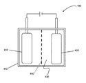
- FIG. 4 is a schematic diagram of an electric double layer capacitor provided with the electrode material of the present invention.
- the electric double layer capacitor of the present invention includes at least an electrode and an electrolyte.
- a positive electrode 410 and a negative electrode 420 are immersed in an electrolyte 430 as electrodes.
- the positive electrode 410 and the negative electrode 420 are made of the electrode material 100 described in the first embodiment.
- the electrolyte 430 is an ionic liquid.
- the ionic liquid is the same as the ionic liquid described in Embodiment 1, but preferably, the ionic liquid of the electrolyte 430 and the ionic liquid contained in the positive electrode 410 and the negative electrode 420 are the same. Thereby, since diffusion of electrolyte 430 to positive electrode 410 and negative electrode 420 is promoted, high rate characteristics can be achieved.
- the electric double layer capacitor 400 further includes a separator 440 between the positive electrode 410 and the negative electrode 420 to isolate the positive electrode 410 and the negative electrode 420.
- the material of the separator 440 is, for example, fluoropolymer, polyether such as polyethylene oxide or polypropylene oxide, polyolefin such as polyethylene or polypropylene, polyacrylonitrile, polyvinylidene chloride, polymethyl methacrylate, polymethyl acrylate, polyvinyl alcohol, polymethacrylo It is a material selected from nitrile, polyvinyl acetate, polyvinyl pyrrolidone, polyethyleneimine, polybutadiene, polystyrene, polyisoprene, polyurethane polymers and derivatives thereof, cellulose, paper, and nonwoven fabric.
- fluoropolymer polyether such as polyethylene oxide or polypropylene oxide
- polyolefin such as polyethylene or polypropylene
- polyacrylonitrile polyvinylidene chloride
- polymethyl methacrylate polymethyl acrylate
- polyvinyl alcohol polymethacrylo It is a material selected from nitrile,
- the positive electrode 410, the negative electrode 420, the electrolyte 430, and the separator 440 described above are accommodated in the cell 450. Further, each of the positive electrode 410 and the negative electrode 420 may have an existing current collector.
- Such an electric double layer capacitor 400 may be a chip type, a coin type, a mold type, a pouch type, a laminate type, a cylindrical type, a square type or the like, and is used in a module in which a plurality of these are connected. May be.
- the anion of the ionic liquid that is the electrolyte 430 is adsorbed on the positive electrode 410, and the cation of the ionic liquid that is the electrolyte 430 is adsorbed on the negative electrode 420, respectively.
- an electric double layer is formed on the surface of each of the positive electrode 410 and the negative electrode 420 and is charged.
- the positive electrode 410 and the negative electrode 420 are formed from the electrode material described in Embodiment 1, adsorption and diffusion of cations and anions are facilitated, and high rate characteristics can be achieved.
- the positive electrode 410 and the negative electrode 420 are formed from the electrode material described in Embodiment 1, many ions can be adsorbed on a large specific surface area and high energy density can be achieved.
- the anions and cations adsorbed on the positive electrode 410 and the negative electrode 420 are desorbed and discharged.
- the positive electrode 410 and the negative electrode 420 are formed from the electrode materials described in the first embodiment, desorption / diffusion of cations and anions is facilitated, and high rate characteristics can be achieved.
- output density can also be improved with ease of desorption / diffusion.
- the electric double layer capacitor 400 of the present invention uses the electrode material of the present invention, it enables quick charging and has a high energy density and a high output density. Moreover, since the formation of an electric double layer is used for charging / discharging, it is excellent in repeated use.
- the electric double layer capacitor 400 of the present invention can be used for wind power generation, electric vehicles and the like.
- the electrode material of the present invention may be applied to a lithium ion battery.
- the lithium ion battery of the present invention includes at least an electrode and an electrolyte, as in the electric double layer capacitor 400 of the present invention of FIG. 4, but the positive electrode 410 has at least an active material capable of adsorbing and desorbing lithium ions. The content is different.
- the positive electrode 410 is typically represented by LiMO 2 (M is an element selected from the group consisting of Ni, Co, Mn, Fe, Ti, Zr, Al, Mg, Cr, and V).
- Li metal oxide is known, but a material for a positive electrode applied to an existing lithium ion battery is applied.
- the electrode material of the present invention coated with Li metal may be used as the positive electrode 410.
- Li When a voltage is applied to the lithium ion battery, Li is ionized from the positive electrode, and is adsorbed and accumulated on the negative electrode.
- the negative electrode is made of the electrode material of the present invention, the diffusion of Li ions is promoted, so that a high energy density can be achieved with a large specific surface area and a large pore volume while achieving high rate characteristics. In this way, the lithium ion battery is charged.
- the lithium ion battery of the present invention uses the electrode material of the present invention, it can be charged quickly and has a high energy density and a high output density.
- the lithium ion battery of the present invention can be used in portable electronic devices such as notebook computers and mobile phones.
- Example 1 an electrode material containing 1-ethyl-3-methylimidazolium tetrafluoroborate (EMIMBF 4 ) as an ionic liquid was produced in a laminate in which reduced graphene oxide (RGO) was laminated.
- EMIMBF 4 1-ethyl-3-methylimidazolium tetrafluoroborate
- graphene oxide was produced from natural graphite powder using the modified Hummers method.
- the graphite powder was mixed with sulfuric acid and sodium nitrate in an ice bath. After these mixtures were stirred, sodium permanganate was slowly added so that the temperature did not exceed 20 ° C. These mixtures were reacted in a 35 ° C. water bath for 1 hour. Thereby, the mixture became a paste.
- a suspension was prepared by adding GO to water as a polar solvent and EMIMBF 4 as an ionic liquid (step S210 in FIG. 2). Specifically, powdered GO is dispersed in water and subjected to ultrasonic treatment for 2 hours to prepare a 1 mg / mL uniform GO aqueous solution, and EMIMBF 4 (0.5 mL) is added as an ionic liquid to this GO aqueous solution (100 mL). ) And stirred for 30 minutes to obtain a suspension.
- the porous structure of the product was evaluated by a Raman spectroscopic apparatus (RAMAN-11 manufactured by Nanophoton Co., Ltd.) using Raman spectroscopy.
- the wavelength of the light source was 532 nm.
- the results are shown in FIG.
- the presence of an ionic liquid in the product was measured by a Fourier transform infrared spectrometer (FT-IR, Thermo Fisher Scientific, Inc. Nicolet 6700) using Fourier transform infrared spectroscopy. The results are shown in FIG.
- the specific surface area and pore distribution of the product were measured by the BET method.
- an Autosorb-iQ analyzer manufactured by Quantachrome Corporation was used for the measurement.
- the results are shown in FIG.
- the specific surface area and pore volume were calculated based on the amount of adsorption in the relative pressure (P / P 0 ) range of 0.05 to 0.3.
- the results are shown in Table 2.
- an electric double layer capacitor (supercapacitor) using the product as an electrode was manufactured.
- the specific manufacturing procedure was as follows.
- the product (90 wt%) and polytetrafluoroethylene (PTFE, 10 wt%) were dispersed in ethanol and sonicated to obtain a suspension.
- the suspension was passed through a porous membrane by vacuum filtration.
- This porous membrane was dried in vacuum for 24 hours, and the membrane made of the product obtained by vacuum filtration and PTFE was cut into a circle, and this was used as an electrode.
- the electrode was circular with a diameter of 15 mm and weighed about 1 mg.
- a porous separator (440 in FIG. 4) is placed between these electrodes (410 and 420 in FIG.
- Electrochemical measurement of the electric double layer capacitor was performed using a multi-channel potentiostat galvanostat (manufactured by Bio-Logic, VMP-300). Specific capacity-voltage measurement (CV measurement) and galvanostat charge / discharge measurement were performed in a potential range of 0 V to 3.5 V at room temperature. The results are shown in FIG. 10 and FIG.
- Cs 4I / (mdV / dt).
- I (A) is a constant current
- m (g) is the total weight of the two electrodes
- dV / dt (V / s) is Vmax (voltage at the start of discharge) and 1/2 Vmax.
- Is a slope obtained by linear fitting of the discharge curve. The results are shown in FIG. 13, Table 3 and Table 4.
- Comparative Example 2 In Comparative Example 2, an electrode material containing a laminate in which reduced graphene oxide (RGO) was laminated without using an ionic liquid was manufactured. The same as Example 1 except that no ionic liquid was used.
- RGO reduced graphene oxide
- Example 1 the morphology and structure of the product obtained in Comparative Example 2 were observed using SEM and TEM. The results are shown in FIGS. 5 (a) and 5 (b) and FIGS. 6 (a) and 6 (b).
- Example 1 the product obtained in Comparative Example 2 was evaluated by Raman spectroscopy and Fourier transform infrared spectroscopy. The results are shown in FIG. 7 and FIG. Furthermore, the specific surface area and pore distribution of the product obtained in Comparative Example 2 were measured, and the specific surface area and pore volume were calculated. The results are shown in FIG.
- Example 1 an electric double layer capacitor (supercapacitor) using the product obtained in Comparative Example 2 as an electrode was manufactured, CV measurement and galvanostat charge / discharge measurement were performed, and the specific capacity depends on the current density. Sex was calculated. The results are shown in FIG. 10, FIG. 11, FIG. 13, Table 3 and Table 4. Further, a Ragone plot of the electric double layer capacitor manufactured in Comparative Example 2 was created, cycle characteristics were measured, and EIS measurement was performed. The results are shown in FIGS.
- Example 3 In Example 3, as in Example 1, 1-ethyl-3-methylimidazolium tetrafluoroborate (EMIMBF 4 ) is contained as an ionic liquid in a laminate in which reduced graphene oxide (RGO) is laminated. An electrode material was manufactured. However, it was the same as Example 1 except using 500 mL of GO aqueous solution (1 mg / mL).
- EMIMBF 4 1-ethyl-3-methylimidazolium tetrafluoroborate
- Example 2 In the same manner as in Example 1, the morphology and structure of the product obtained in Example 3 were observed, and the specific surface area and pore distribution were measured. Further, as in Example 1, an electric double layer capacitor (supercapacitor) using the product obtained in Example 3 as an electrode was manufactured, CV measurement and galvanostat charge / discharge measurement were performed, and a Ragone plot, cycle The characteristics were measured and EIS measurement was performed. Here, the result of the galvanostat charge / discharge measurement is shown in FIG.
- Example 4 In Example 4, as in Example 1, 1-ethyl-3-methylimidazolium tetrafluoroborate (EMIMBF 4 ) is contained as an ionic liquid in a laminate in which reduced graphene oxide (RGO) is laminated. An electrode material was manufactured. However, it was the same as Example 1 except that 2 mL of EMIMBF 4 was used.
- EMIMBF 4 1-ethyl-3-methylimidazolium tetrafluoroborate
- Example 2 In the same manner as in Example 1, the morphology and structure of the product obtained in Example 4 were observed, and the specific surface area and pore distribution were measured. Further, as in Example 1, an electric double layer capacitor (supercapacitor) using the product obtained in Example 3 as an electrode was manufactured, CV measurement and galvanostat charge / discharge measurement were performed, and a Ragone plot, cycle The characteristics were measured and EIS measurement was performed. Here, the result of the galvanostat charge / discharge measurement is shown in FIG.
- Example 5 In Example 5, as in Example 1, 1-ethyl-3-methylimidazolium-bis (trifluoromethanesulfonyl) imide (EMITFSI) was used as an ionic liquid in a laminate in which reduced graphene oxide (RGO) was laminated. ) was produced. However, it was the same as Example 1 except that 0.5 mL of EMITFSI was used as the ionic liquid.
- EMITFSI 1-ethyl-3-methylimidazolium-bis (trifluoromethanesulfonyl) imide
- Example 1 As in Example 1, the morphology and structure of the product obtained in Example 5 were observed, and the specific surface area and pore distribution were measured. Similarly to Example 1, the product obtained in Example 3 was used as an electrode, EMITFSI was used as an electrolyte, an electric double layer capacitor (supercapacitor) was manufactured, and CV measurement and galvanostat charge / discharge measurement were performed. The Rone plot and cycle characteristics were measured, and EIS measurement was performed. Here, the result of the galvanostat charge / discharge measurement is shown in FIG.
- Table 1 shows a list of experimental conditions for the above examples and comparative examples for simplicity.
- the weight of the ionic liquid used for the electrode material of the present invention was calculated assuming that the specific gravity of EMIMBF 4 and EMITFSI was 1.294 g / ml and 1.53 g / ml, respectively. Further, when GO was reduced to RGO, the weight of RGO was calculated based on being 1/2 of the weight of GO.
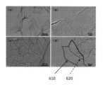
- FIG. 5 is a diagram showing SEM images of the products of Example 1 and Comparative Example 2.
- FIGS. 5 (a) and 5 (b) are SEM images of the product of Comparative Example 2
- FIGS. 5 (c) and 5 (d) are SEM images of the product of Example 1.
- the product of Example 1 represented a porous structure consisting of a layered curved sheet. From this, the product of Example 1 can adsorb many ions that are electrolytes on the surface, suggesting an increase in energy density.
- the products of Examples 3 to 5 also showed the same morphology as Example 1.
- FIG. 6 is a diagram showing TEM images of the products of Example 1 and Comparative Example 2.
- FIGS. 6 (a) and 6 (b) are TEM images of the product of Comparative Example 2
- FIGS. 6 (c) and 6 (d) are TEM images of the product of Example 1.
- FIGS. 6C and 6D the product of Example 1 is similar to the SEM image, although the layered curved RGO sheets are laminated, compared with that of Comparative Example 2. It turned out to be very thin.
- FIG. 6D shows that the thin RGO sheet 620 is positioned above the RGO sheet 610, and each RGO sheet is laminated in a single-layer peeled state.
- the products of Examples 3 to 5 also showed the same morphology as Example 1.
- the ionic liquid functions as a surfactant or a soft template, and maintains the state where the RGO is peeled off from the single layer while maintaining the state where the RGO is separated from the interlayer. It was confirmed that a laminate composed of RGO holding the liquid was obtained.
- FIG. 7 is a diagram showing the Raman spectra of the products of Example 1 and Comparative Example 2.
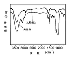
- FIG. 8 is a diagram showing FT-IR spectra of the products of Example 1 and Comparative Example 2.
- the FT-IR spectrum of the product of Example 1 has wave numbers of 3160 cm ⁇ 1 , 3090 cm ⁇ 1 , 1572 cm ⁇ 1 and 1065 cm. A noticeable peak different from that of the product of Comparative Example 2 was observed at -1 . These peaks, CH x unsaturated bond, C-N bond from imidazolium ring, and, [BF 4] - corresponding to stretching vibration of BF binding anions. This indicates that the product of Example 1 has an ionic liquid located on the surface of RGO. Although not shown, the products of Examples 3 to 4 also showed the same spectrum as the FT-IR spectrum of the product of Example 1.
- the product of the present invention was a material including a laminate in which RGO containing an ionic liquid was laminated. Furthermore, when the manufacturing method (FIG. 2) of this invention was used, it turned out that the material containing the laminated body which the RGO containing the above-mentioned ionic liquid laminated
- FIG. 9 is a graph showing nitrogen adsorption / desorption isotherms and pore size distributions of the products of Example 1 and Comparative Example 2.
- FIG. 9 (a) shows a nitrogen adsorption / desorption isotherm, that of the product of Comparative Example 2 is of type IV indicating that mesopores are present, that of the product of Example 1 is mesopores And the combination of type III and IV indicating the presence of macropores. From comparison between Example 1 and Comparative Example 2, it can be seen that the macropores were generated by the ionic liquid. This result is in good agreement with the results of FIGS. 5 and 6 (the product of Example 1 exhibits a porous structure). Although not shown, the nitrogen adsorption and desorption isotherms of the products of Examples 3-5 also showed a combination of types III and IV.
- the material of the present invention has mesopores and macropores, when the material of the present invention is employed in an electricity storage device in which the electrolyte is an ionic liquid, ions can be adsorbed into the mesopores, Since the ionic liquid that is an electrolyte can be retained, the ion diffusion distance can be shortened, and thus high rate characteristics can be achieved.
- FIG. 9 (b) shows the pore size distribution. It was found that the pore peak of the product of Example 1 is at 4 nm and mainly has mesopores having a diameter in the range of 2 nm to 6 nm. On the other hand, the pore peak of the product of Comparative Example 2 was at 3.5 nm, which was smaller than that of the product of Example 1. This indicates that the RGO in the product of Example 1 is more monolayer separated than that in the product of Comparative Example 2 due to the function of the ionic liquid as a surfactant. Table 2 shows the specific surface area and pore volume calculated from FIG.
- FIG. 10 is a diagram showing specific capacity-voltage curves (CV curves) of the products of Example 1 and Comparative Example 2.
- FIGS. 10 (a) and 10 (b) show the results of the sweep rates of 50 mV / s and 500 mV / S, respectively.
- the products of Example 1 and Comparative Example 2 exhibited a rectangular CV curve representing an ideal electric double layer capacitor.
- the product of Example 1 exhibited a rectangular CV curve, whereas the product of Comparative Example 2 did not exhibit a rectangular CV curve. It was. From this, it was confirmed that the product of Example 1 functions as an electrode material having excellent rate characteristics.
- the CV curves of the products of Examples 3-5 showed similar results to those of the product of Example 1.
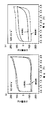
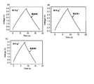
- FIG. 11 is a diagram showing charge / discharge curves of the products of Example 1 and Comparative Example 2.
- FIG. 12 shows the charge / discharge curves of the products of Examples 3 to 5.
- FIGS. 11A and 11B are constant current charge / discharge curves with current densities of 2 A / g and 20 A / g, respectively.
- FIG. 12 is a constant current charge / discharge curve with a current density of 20 A / g.
- the product showed a constant current charge / discharge curve typical of an electric double layer capacitor.
- the charge / discharge curve of the product of Example 1 is substantially longer than that of Comparative Example 2, although the discharge time is slightly longer. It didn't change.
- FIG. 11B when the current density increased, the discharge time of the charge / discharge curve of the product of Example 1 was significantly longer than that of Comparative Example 2.
- FIG. 12 similar to the product of Example 1, the products of Examples 3-5 showed similar results with long discharge times. From this, it was confirmed that the products of Examples 1, 3 to 5 function as electrode materials having excellent rate characteristics.
- FIG. 13 is a graph showing the current density dependence of the specific capacities of the products of Example 1 and Comparative Example 2.
- the specific capacity of the product of Example 1 at a current density of 0.5 A / g is 135 F / g, slightly larger than that of the product of Comparative Example 2 (129 F / g). It was. This is because the specific surface area of the product of Example 1 is larger than that of the product of Comparative Example 2 as described with reference to Table 2.
- the specific capacity of the product of Example 1 at a current density of 20 A / g was 114 F / g, whereas that of the product of Comparative Example 2 was 68 F / g.
- the specific capacity of the product of Comparative Example 2 decreased from 129 F / g (@ 0.5 A / g) to 68 F / g (@ 20 A / g), and its retention rate was only 53%, with very low retention It was a characteristic.
- the specific capacity of the product of Example 1 slightly decreased from 135 F / g (@ 0.5 A / g) to 114 F / g (@ 20 A / g), but the retention rate was as high as 85%. It showed high retention characteristics.
- the products of Examples 3 to 5 also had a high specific capacity and high retention characteristics even at a high current density, like the products of Example 1.
- the product of the present invention is a material including a laminate in which RGO containing an ionic liquid is laminated, and is suitable as an electrode material for an electricity storage device using the ionic liquid as an electrolyte.
- FIG. 14 is a graph showing a Ragone plot of the products of Example 1 and Comparative Example 2.
- the energy density of the product of Example 1 did not substantially decrease with the increase of the power density, compared with that of the product of Comparative Example 2.
- the energy density of the product of Example 1 at a power density of 18 kW / kg was 49 Wh / kg, significantly higher than that of the product of Comparative Example 2 (29 Wh / kg).
- the products of Examples 3 to 5 showed the same tendency as the product of Example 1.
- FIG. 15 is a diagram showing cycle characteristics of the products of Example 1 and Comparative Example 2.
- Example 1 had a high capacity retention of 92% even after 2000 repeated cycles at a current density of 10 A / g, which was higher than that of the product of Comparative Example 2 (82%). Although not shown, the products of Examples 3 to 5 showed the same results as the product of Example 1.
- the product of the present invention is suitable as an electrode material for an electricity storage device using an ionic liquid as an electrolyte.
- FIG. 16 is a diagram showing a Nyquist plot of the products of Example 1 and Comparative Example 2.
- the equivalent series resistance (ESR; 4.7 ⁇ ) obtained from the x-axis intercept of the product of Example 1 is smaller than that of the product of Comparative Example 2 (6.1 ⁇ ). It was found that the product of Example 1 can make good contact with the current collector. This is because the product of Example 1 has a porous structure consisting of hierarchical curved sheets, as described with reference to FIGS. Based on being offered.
- the diameter of the semicircle represents the charge transport resistance (R ct ) and is related to the transport of electrolyte ions at the interface between the electrode and the electrolyte.
- the R ct of the product of Example 1 was 0.86 ⁇ , which was only a quarter of the R ct (3.5 ⁇ ) of the product of Comparative Example 2.
- the resistance is reduced, the adsorption / desorption of ions is promoted, and the rate characteristics of the electric double layer capacitor are improved.
- the R ct of the products of Examples 3-5 was also low.
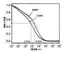
- FIG. 17 is a diagram showing the frequency dependence of the normalized specific capacity of the products of Example 1 and Comparative Example 2.
- the operating frequencies f 0.5 of the products of Example 1 and Comparative Example 2 were 18.60 Hz and 5.75 Hz, respectively.
- the product of the present invention is a material including a laminate in which RGO containing an ionic liquid is laminated, and it is confirmed that the consistency between the product of the present invention and the electrolyte that is the ionic liquid is improved. It was done.
- the electrode material of the present invention is used in an electricity storage device using an ionic liquid as an electrolyte, the rate characteristics of the electrode material are improved, and quick charge / discharge is possible while achieving high output density and high energy density.
- an electricity storage device is an electric double layer capacitor, it is advantageous for wind power generation, electric vehicles and the like.
- an electricity storage device is a lithium ion battery, it is advantageous for portable electronic devices such as notebook computers and mobile phones.
- Electrode material 110 Graphene oxide (RGO) 120 laminate 130 ionic liquid 400 electric double layer capacitor 410 positive electrode 420 negative electrode transmission 430 electrolyte 440 separator 450 cell
Landscapes
- Engineering & Computer Science (AREA)
- Chemical & Material Sciences (AREA)
- Power Engineering (AREA)
- Chemical Kinetics & Catalysis (AREA)
- Electrochemistry (AREA)
- Microelectronics & Electronic Packaging (AREA)
- General Chemical & Material Sciences (AREA)
- Manufacturing & Machinery (AREA)
- Materials Engineering (AREA)
- Inorganic Chemistry (AREA)
- General Physics & Mathematics (AREA)
- Condensed Matter Physics & Semiconductors (AREA)
- Crystallography & Structural Chemistry (AREA)
- Nanotechnology (AREA)
- Physics & Mathematics (AREA)
- Electric Double-Layer Capacitors Or The Like (AREA)
- Secondary Cells (AREA)
- Battery Electrode And Active Subsutance (AREA)
Abstract
イオン液体を電解質に用いた蓄電デバイスにおいて、レート特性を向上させる電極材料、その製造方法、および、それを用いた蓄電デバイスを提供することを課題としている。 本発明の電極材料は、還元された酸化グラフェンが積層した積層体を含み、積層体は、還元された酸化グラフェン間にイオン液体を含有する。
Description
本発明は、酸化グラフェンを用いた電極材料、その製造方法、および、それを用いた蓄電デバイスに関する。
電気二重層キャパシタやリチウムイオン電池といった蓄電デバイスは、容量が大きく、注目を集めている。電極材料にグラフェンを用いた蓄電デバイスにおいて、電解質として大きな電位窓を有するイオン液体を用いることが期待されている。しかしながら、イオン液体は、分子が大きく、粘性が高く、伝導率が小さいために、グラフェンへのイオン液体のレート特性(rate capability)が低い。このため、イオン液体を蓄電デバイスに用いても、素早い充放電ができない。
このような問題を解決するために、イオン液体と溶媒分子とを混合した混合物を電解質に用いる技術がある(例えば、非特許文献1を参照)。非特許文献1によれば、イオン液体としてN-ブチル-n-メチルピロリジニウムビス(トリフルオロメタンスルホニル)イミド(PYR14TFSI)に、溶媒分子としてアセトニトリル、ブチルニトリル、ベンゾニトリル、プロピレン炭酸塩、ジメチル炭酸塩等を添加することにより、伝導率が向上し得る。
別の技術には、イオン液体と単層ナノチューブとを混合した混合物を電解質に用いる技術がある(例えば、非特許文献2を参照)。非特許文献2によれば、イオン液体として1-エチル-3-メチルイミダゾリウムテトラフルオロボレート(EMIBF4)に単層ナノチューブを添加することにより、伝導率が向上し得る。
しかしながら、非特許文献1および非特許文献2のいずれも、蓄電デバイス向けにイオン液体の特性を改善することを目的としており、電極材料には注目されていなかった。
V.Ruizら,RSC Advances,2012,2,5591~5598
C.Kongら,Chemical Communications,2013,49,10727
本発明の課題は、イオン液体を電解質に用いた蓄電デバイスにおいて、レート特性を向上させる電極材料、その製造方法、および、それを用いた蓄電デバイスを提供することである。
本発明による還元された酸化グラフェンが積層した積層体を含む電極材料は、前記積層体は、前記還元された酸化グラフェン間にイオン液体を含有し、これにより上記課題を達成する。
還元された酸化グラフェンに対する含有されるイオン液体との重量比は、0.01以上1.00以下の範囲であってもよい。
還元された酸化グラフェンに対する含有されるイオン液体との重量比は、0.02以上0.60以下の範囲であってもよい。
前記積層体の比表面積は、350m2/g以上500m2/g以下の範囲であってもよい。
前記積層体の比表面積は、420m2/g以上450m2/g以下の範囲であってもよい。
前記積層体の細孔容積は、0.75cc/g以上1.5cc/g以下の範囲であってもよい。
前記積層体の細孔容積は、0.85cc/g以上0.95cc/g以下の範囲であってもよい。
前記イオン液体は、1-エチル-3-メチルイミダゾリウムテトラフルオロボレート(EMIMBF4)、1-エチル-3-メチルイミダゾリウム-ビス(フルオロスルホニル)イミド(EMIFSI)、1-エチル-3-メチルイミダゾリウム-ビス(トリフルオロメタンスルホニル)イミド(EMITFSI)、1-ブチル-3-メチルイミダゾリウム-ビス(トリフルオロメタンスルホニル)イミド(BMITFSI)、1-ヘキシル-3-メチルイミダゾリウムテトラフルオロボレート(HMIBF4)、1-ヘキシル-3-メチルイミダゾリウム-ビス(トリフルオロメタンスルホニル)イミド(HMITFSI)、1-エチル-3-メチルイミダゾリウム-フルオロハイドロジェネート(EMI(FH)2.3F)、N,N-ジエチル-N-メチル-N-(2-メトキシエチル)-テトラフルオロボレート(DEMEBF4)、N,N-ジエチル-N-メチル-N-(2-メトキシエチル)-ビス(トリフルオロメタンスルホニル)イミド(DEMETFSI)、N-メチル-N-プロピルピペリジニウム-ビス(トリフルオロメタンスルホニル)イミド(PP13TFSI)、トリエチルスルホニウム-ビス(トリフルオロメタンスルホニル)イミド(TESTFSI)、N-メチル-Nプロピルピロリジニウム-ビス(トリフルオロメタンスルホニル)イミド(P13TFSI)、トリエチルオクチルホスホニウム-ビス(トリフルオロメタンスルホニル)イミド(P2228TFSI)、N-メチル-メトキシメチルピロリジニウム-テトラフルオロボレート(C13BF4)、リチウム-ビス(フルオロスルホニル)イミド(LiFSI)、および、リチウム-ビス(トリフルオロメタンスルホニル)イミド(LiTFSI)からなる群から少なくとも1つ選択されてもよい。
前記積層体は、2nm以上6nm以下の範囲の直径を有するメソ細孔、および、50nm以上の直径を有するマクロ細孔を有してもよい。
前記積層体は、電流密度20A/gにおいて、80F/g以上140F/g以下の範囲の比容量を有してもよい。
本発明による電極材料を製造する方法は、極性溶媒に酸化グラフェンおよびイオン液体を添加した懸濁液を調製するステップと、前記懸濁液に還元剤を添加し、還流するステップとを包含し、これにより上記課題を達成する。
前記調製するステップにおいて、前記酸化グラフェンに対するイオン液体の重量比は、0.005以上0.5以下であってもよい。
前記調製するステップにおいて、前記酸化グラフェンに対するイオン液体の重量比は、0.01以上0.3以下であってもよい。
前記極性溶媒は、水、ジメチルスルホキシド(DMSO)、N,N-ジメチルスルホアミド(DMF)およびエタノールからなる群から選択されてもよい。
前記イオン液体は、1-エチル-3-メチルイミダゾリウムテトラフルオロボレート(EMIBF4)、1-エチル-3-メチルイミダゾリウム-ビス(フルオロスルホニル)イミド(EMIFSI)、1-エチル-3-メチルイミダゾリウム-ビス(トリフルオロメタンスルホニル)イミド(EMITFSI)、1-ブチル-3-メチルイミダゾリウム-ビス(トリフルオロメタンスルホニル)イミド(BMITFSI)、1-ヘキシル-3-メチルイミダゾリウムテトラフルオロボレート(HMIBF4)、1-ヘキシル-3-メチルイミダゾリウム-ビス(トリフルオロメタンスルホニル)イミド(HMITFSI)、1-エチル-3-メチルイミダゾリウム-フルオロハイドロジェネート(EMI(FH)2.3F)、N,N-ジエチル-N-メチル-N-(2-メトキシエチル)-テトラフルオロボレート(DEMEBF4)、N,N-ジエチル-N-メチル-N-(2-メトキシエチル)-ビス(トリフルオロメタンスルホニル)イミド(DEMETFSI)、N-メチル-N-プロピルピペリジニウム-ビス(トリフルオロメタンスルホニル)イミド(PP13TFSI)、トリエチルスルホニウム-ビス(トリフルオロメタンスルホニル)イミド(TESTFSI)、N-メチル-Nプロピルピロリジニウム-ビス(トリフルオロメタンスルホニル)イミド(P13TFSI)、トリエチルオクチルホスホニウム-ビス(トリフルオロメタンスルホニル)イミド(P2228TFSI)、N-メチル-メトキシメチルピロリジニウム-テトラフルオロボレート(C13BF4)、リチウム-ビス(フルオロスルホニル)イミド(LiFSI)、および、リチウム-ビス(トリフルオロメタンスルホニル)イミド(LiTFSI)からなる群から少なくとも1つ選択されてもよい。
前記還元剤は、ヒドラジン、ジメチルヒドラジン、アスコルビン酸、ヒドロキノン、水素化硼素ナトリウム(NaBH4)、テトラブチルアンモニウムブロマイド(TBAB)、LiAlH4、エチレングリコール、ポリエチレングリコール、ヨウ化水素、および、N,N-ジエチルヒドロキシルアミンからなる群から少なくとも1つ選択されてもよい。
本発明による電極と、電解質とを備えた蓄電デバイスは、前記電極は、上述の電極材料からなり、これにより上記課題を達成する。
前記蓄電デバイスは、電気二重層キャパシタであり、前記電解質は、イオン液体であり、前記イオン液体は、前記電極材料中に含有されるイオン液体と同じであってもよい。
前記蓄電デバイスは、リチウムイオン電池であり、前記電解質は、リチウムを含有するイオン液体であり、前記リチウムを含有するイオン液体は、前記電極材料中に含有されるイオン液体と同じであってもよい。
還元された酸化グラフェンに対する含有されるイオン液体との重量比は、0.01以上1.00以下の範囲であってもよい。
還元された酸化グラフェンに対する含有されるイオン液体との重量比は、0.02以上0.60以下の範囲であってもよい。
前記積層体の比表面積は、350m2/g以上500m2/g以下の範囲であってもよい。
前記積層体の比表面積は、420m2/g以上450m2/g以下の範囲であってもよい。
前記積層体の細孔容積は、0.75cc/g以上1.5cc/g以下の範囲であってもよい。
前記積層体の細孔容積は、0.85cc/g以上0.95cc/g以下の範囲であってもよい。
前記イオン液体は、1-エチル-3-メチルイミダゾリウムテトラフルオロボレート(EMIMBF4)、1-エチル-3-メチルイミダゾリウム-ビス(フルオロスルホニル)イミド(EMIFSI)、1-エチル-3-メチルイミダゾリウム-ビス(トリフルオロメタンスルホニル)イミド(EMITFSI)、1-ブチル-3-メチルイミダゾリウム-ビス(トリフルオロメタンスルホニル)イミド(BMITFSI)、1-ヘキシル-3-メチルイミダゾリウムテトラフルオロボレート(HMIBF4)、1-ヘキシル-3-メチルイミダゾリウム-ビス(トリフルオロメタンスルホニル)イミド(HMITFSI)、1-エチル-3-メチルイミダゾリウム-フルオロハイドロジェネート(EMI(FH)2.3F)、N,N-ジエチル-N-メチル-N-(2-メトキシエチル)-テトラフルオロボレート(DEMEBF4)、N,N-ジエチル-N-メチル-N-(2-メトキシエチル)-ビス(トリフルオロメタンスルホニル)イミド(DEMETFSI)、N-メチル-N-プロピルピペリジニウム-ビス(トリフルオロメタンスルホニル)イミド(PP13TFSI)、トリエチルスルホニウム-ビス(トリフルオロメタンスルホニル)イミド(TESTFSI)、N-メチル-Nプロピルピロリジニウム-ビス(トリフルオロメタンスルホニル)イミド(P13TFSI)、トリエチルオクチルホスホニウム-ビス(トリフルオロメタンスルホニル)イミド(P2228TFSI)、N-メチル-メトキシメチルピロリジニウム-テトラフルオロボレート(C13BF4)、リチウム-ビス(フルオロスルホニル)イミド(LiFSI)、および、リチウム-ビス(トリフルオロメタンスルホニル)イミド(LiTFSI)からなる群から少なくとも1つ選択されてもよい。
前記積層体は、2nm以上6nm以下の範囲の直径を有するメソ細孔、および、50nm以上の直径を有するマクロ細孔を有してもよい。
前記積層体は、電流密度20A/gにおいて、80F/g以上140F/g以下の範囲の比容量を有してもよい。
本発明による電極材料を製造する方法は、極性溶媒に酸化グラフェンおよびイオン液体を添加した懸濁液を調製するステップと、前記懸濁液に還元剤を添加し、還流するステップとを包含し、これにより上記課題を達成する。
前記調製するステップにおいて、前記酸化グラフェンに対するイオン液体の重量比は、0.005以上0.5以下であってもよい。
前記調製するステップにおいて、前記酸化グラフェンに対するイオン液体の重量比は、0.01以上0.3以下であってもよい。
前記極性溶媒は、水、ジメチルスルホキシド(DMSO)、N,N-ジメチルスルホアミド(DMF)およびエタノールからなる群から選択されてもよい。
前記イオン液体は、1-エチル-3-メチルイミダゾリウムテトラフルオロボレート(EMIBF4)、1-エチル-3-メチルイミダゾリウム-ビス(フルオロスルホニル)イミド(EMIFSI)、1-エチル-3-メチルイミダゾリウム-ビス(トリフルオロメタンスルホニル)イミド(EMITFSI)、1-ブチル-3-メチルイミダゾリウム-ビス(トリフルオロメタンスルホニル)イミド(BMITFSI)、1-ヘキシル-3-メチルイミダゾリウムテトラフルオロボレート(HMIBF4)、1-ヘキシル-3-メチルイミダゾリウム-ビス(トリフルオロメタンスルホニル)イミド(HMITFSI)、1-エチル-3-メチルイミダゾリウム-フルオロハイドロジェネート(EMI(FH)2.3F)、N,N-ジエチル-N-メチル-N-(2-メトキシエチル)-テトラフルオロボレート(DEMEBF4)、N,N-ジエチル-N-メチル-N-(2-メトキシエチル)-ビス(トリフルオロメタンスルホニル)イミド(DEMETFSI)、N-メチル-N-プロピルピペリジニウム-ビス(トリフルオロメタンスルホニル)イミド(PP13TFSI)、トリエチルスルホニウム-ビス(トリフルオロメタンスルホニル)イミド(TESTFSI)、N-メチル-Nプロピルピロリジニウム-ビス(トリフルオロメタンスルホニル)イミド(P13TFSI)、トリエチルオクチルホスホニウム-ビス(トリフルオロメタンスルホニル)イミド(P2228TFSI)、N-メチル-メトキシメチルピロリジニウム-テトラフルオロボレート(C13BF4)、リチウム-ビス(フルオロスルホニル)イミド(LiFSI)、および、リチウム-ビス(トリフルオロメタンスルホニル)イミド(LiTFSI)からなる群から少なくとも1つ選択されてもよい。
前記還元剤は、ヒドラジン、ジメチルヒドラジン、アスコルビン酸、ヒドロキノン、水素化硼素ナトリウム(NaBH4)、テトラブチルアンモニウムブロマイド(TBAB)、LiAlH4、エチレングリコール、ポリエチレングリコール、ヨウ化水素、および、N,N-ジエチルヒドロキシルアミンからなる群から少なくとも1つ選択されてもよい。
本発明による電極と、電解質とを備えた蓄電デバイスは、前記電極は、上述の電極材料からなり、これにより上記課題を達成する。
前記蓄電デバイスは、電気二重層キャパシタであり、前記電解質は、イオン液体であり、前記イオン液体は、前記電極材料中に含有されるイオン液体と同じであってもよい。
前記蓄電デバイスは、リチウムイオン電池であり、前記電解質は、リチウムを含有するイオン液体であり、前記リチウムを含有するイオン液体は、前記電極材料中に含有されるイオン液体と同じであってもよい。
本発明による還元された酸化グラフェン(RGO)が積層した積層体を含む電極材料は、RGO間にイオン液体を含有する。RGO間にイオン液体が位置することにより、積層体は大きな比表面積を有する。この結果、本発明の電極材料は高いエネルギー密度を達成できる。また、RGOの表面にイオン液体が位置することにより、RGOの表面自由エネルギーが小さくなるので、同じ種類のイオン液体である電解質の、RGOへの拡散および吸脱着が促進される。RGO間がイオン液体により離間しているため、イオン拡散のパスを増大し、電解質のイオン輸送を促進できる。この結果、本発明の電極材料を電解質がイオン液体である蓄電デバイスの電極に用いれば、レート特性が向上し得る。
本発明による電極材料を製造する方法は、極性溶媒に酸化グラフェンおよびイオン液体を添加した懸濁液を調製するステップと、懸濁液に還元剤を添加し、還流するステップとを包含する。酸化グラフェンとイオン液体とを混合することにより、イオン液体が界面活性剤のように機能し、酸化グラフェンが再積層するのを抑制し、自己組織的に酸化グラフェン間にイオン液体が位置しながら酸化グラフェンが積層する。このようにして得た積層体を還元すればよいので、ワンポット合成が可能であり、複雑な装置を不要とするので、工業生産に有利である。
以下、図面を参照しながら本発明の実施の形態を説明する。なお、同様の要素には同様の番号を付し、その説明を省略する。
(実施の形態1)
実施の形態1では、本発明の電極材料およびその製造方法について説明する。
実施の形態1では、本発明の電極材料およびその製造方法について説明する。
図1は、本発明の電極材料の模式図である。
本発明の電極材料100は、還元された酸化グラフェン110(簡単のため、RGOと称する)が集積した積層体120を含む。積層体120は、RGO110間にイオン液体130を含有する。RGO110間にイオン液体130が位置することにより、RGO110が確実に単層剥離された状態となるので、積層体120は大きな比表面積を有する。これにより、本発明の電極材料100は高いエネルギー密度を達成できる。また、RGO110の表面にイオン液体130が位置することにより、RGO110の表面自由エネルギーが小さくなるので、同じ種類のイオン液体である電解質の、RGO110への拡散および吸脱着が促進される。さらに、RGO110間がイオン液体130により離間しているため、イオン拡散のパスを増大し、電解質のイオン輸送を促進できる。この結果、本発明の電極材料100を電解質がイオン液体である蓄電デバイスの電極に用いれば、レート特性が向上し得る。
RGO110間にイオン液体130が位置することにより、RGOは物理的に離間する。その距離dは、0.5nm以上2nm以下の範囲であり、電解質であるイオンの拡散を容易にする。
RGO110は、グラファイトから単層剥離されたナノシートである酸化グラフェンのカルボニル基を除去することによって得られる。RGO110は、カルボニル基が除去されているので、高い導電性を有し、電極材料に好適である。一方で、RGO110は、ヒドロキシ基を有するので、極性溶媒などに対して親和性を有し、蓄電デバイスの構築に有利である。
RGO110は、好ましくは、0.3nm以上1nm以下の厚さを有し、長手方向に1μm以上10μm以下の長さを有する、シート状の形態を有する。このような厚さを有するシート状の形態であれば、グラファイトが実質的に単層剥離されているので、積層体120の比表面積を大きくできるので、エネルギー密度の向上が期待できる。
イオン液体130は、アニオンおよびカチオンの組み合わせからなる塩であるが、室温において液体であり、実質的に蒸気圧が0であるため、不揮発性という特徴を有する。アニオンには、例えば、AlCl4
-、NO2
-、NO3
-、I-、BF4
-、PF6
-、AsF6
-、SbF6
-、NbF6
-、TaF6
-、F(HF)2.3
-、p-CH3PhSO3
-、CH3CO2
-、CF3CO2
-、CH3SO3
-、CF3SO3
-、(CF3SO2)3C-、C3F7CO2
-、C4F9SO3
-、(CF3SO2)2N-、(C2F5SO2)2N-、(CF3SO2)(CF3CO)N-、(CN)2N-等がある。カチオンには、例えば、炭素数1~8のアルキル基を有する、イミダゾリウムイオン、ピリジニウムイオン、ピペリジニウムイオン、ピロリジニウムイオン、スルホニウムイオン等がある。
より具体的には、イオン液体130は、1-エチル-3-メチルイミダゾリウムテトラフルオロボレート(EMIMBF4)、1-エチル-3-メチルイミダゾリウム-ビス(フルオロスルホニル)イミド(EMIFSI)、1-エチル-3-メチルイミダゾリウム-ビス(トリフルオロメタンスルホニル)イミド(EMITFSI)、1-ブチル-3-メチルイミダゾリウム-ビス(トリフルオロメタンスルホニル)イミド(BMITFSI)、1-ヘキシル-3-メチルイミダゾリウムテトラフルオロボレート(HMIBF4)、1-ヘキシル-3-メチルイミダゾリウム-ビス(トリフルオロメタンスルホニル)イミド(HMITFSI)、1-エチル-3-メチルイミダゾリウム-フルオロハイドロジェネート(EMI(FH)2.3F)、N,N-ジエチル-N-メチル-N-(2-メトキシエチル)-テトラフルオロボレート(DEMEBF4)、N,N-ジエチル-N-メチル-N-(2-メトキシエチル)-ビス(トリフルオロメタンスルホニル)イミド(DEMETFSI)、N-メチル-N-プロピルピペリジニウム-ビス(トリフルオロメタンスルホニル)イミド(PP13TFSI)、トリエチルスルホニウム-ビス(トリフルオロメタンスルホニル)イミド(TESTFSI)、N-メチル-Nプロピルピロリジニウム-ビス(トリフルオロメタンスルホニル)イミド(P13TFSI)、トリエチルオクチルホスホニウム-ビス(トリフルオロメタンスルホニル)イミド(P2228TFSI)、N-メチル-メトキシメチルピロリジニウム-テトラフルオロボレート(C13BF4)、リチウム-ビス(フルオロスルホニル)イミド(LiFSI)、および、リチウム-ビス(トリフルオロメタンスルホニル)イミド(LiTFSI)からなる群から少なくとも1つ選択される。これらのイオン液体は、入手可能であり、蓄電デバイスの電解質としても利用可能であるので、本発明の電極材料に用いることができる。
積層体120において、RGO110に対するイオン液体130の割合(重量比、以降では単にRGOとイオン液体との割合と称する)は、好ましくは、0.01以上1.00以下である。割合が0.01未満であると、イオン液体130が少ないため、RGO110がイオン液体を担持することなく再積層し、比表面積を大きくできない場合がある。また、RGO110に位置するイオン液体130が少ないため、RGO110の表面自由エネルギーを小さくすることができないので、電解質であるイオン液体の吸脱着・拡散を促進できない。割合が1.00を超えると、RGO間にイオン液体130が過剰に存在し、電解質であるイオン液体が積層体120へ拡散できない場合がある。
積層体120において、RGO110とイオン液体130との割合は、より好ましくは、0.02以上0.60以下である。これにより、電解質であるイオン液体の積層体120への拡散を確実に促進し得る。
積層体120において、例えば、イオン液体130がEMIMBF4である場合、RGO110とイオン液体130との割合は、より好ましくは、0.02以上0.15以下である。これにより、電解質であるイオン液体の積層体120への拡散を確実に促進し得、高い電流密度においても高い比容量を維持し、保持特性に優れ得る。
積層体120のBET法により求めた比表面積は、好ましくは、350m2/g以上500m2/g以下の範囲である。比表面積が350m2/g未満であると、RGO間にイオン液体が十分に位置しておらず、RGOが単層剥離されていない、あるいは、RGO間に過剰にイオン液体が位置しているので、高いエネルギー密度および高いレート特性が得られない。比表面積が500m2/gを超えると、RGOが単層剥離されているが、イオン液体がRGO間に位置していない場合あり、電解質がイオン液体である蓄電デバイスの電極材料に使えない恐れがある。
積層体120のBET法により求めた比表面積は、より好ましくは、420m2/g以上450m2/g以下の範囲である。この範囲を満たしていれば、グラフェンが単層剥離されており、上述したRGOとイオン液体との割合で層間へのイオン液体の配置がなされたとみなせるので、高いエネルギー密度および高いレート特性を確実にする。
積層体120のBJH法により求めた細孔容積は、好ましくは、0.75cc/g以上1.5cc/g以下の範囲である。細孔容積が0.75cc/g未満であると、積層体120への十分な量の電解質であるイオン液体が拡散できないので、高いエネルギー密度を達成できない。細孔容積が1.5cc/gを超えてもよいが、RGO間にイオン液体が位置するRGOが積層した、良質な積層体を製造することは困難である。積層体120のBJH法により求めた細孔容積は、より好ましくは、0.85cc/g以上0.95cc/g以下の範囲である。この範囲を満たしていれば、上述したRGOとイオン液体との比率で層間へのイオン液体の配置がなされており、層間へ十分な量の電解質であるイオン液体が侵入し、高いエネルギー密度および高いレート特性を確実にする。
積層体120は、2種類の異なる細孔径を有する細孔を有する。詳細には、積層体120は、好ましくは、2nm以上6nm以下の範囲の直径を有するメソ細孔、および、50nm以上の直径を有するマクロ細孔を有する。このような構造により、本発明の電極材料100を電解質がイオン液体である蓄電デバイスに採用した場合、メソ細孔にイオンが吸着し得、マクロ細孔には電解質であるイオン液体が保持され得る。すなわち、電界印加によって、イオンの拡散距離を短くすることができるので、高いレート特性を達成できる。
積層体120は、好ましくは、電流密度20A/gにおいて、80F/g以上140F/g以下の範囲の比容量を有する。すなわち、本発明の積層体120は、高い電流密度においても、高い比容量有するので、保持特性に優れており、電極材料に有利である。
本発明の電極材料100は、積層体120からなってもよいが、電気的特性を維持する限り、積層体120に加えて、バインダ、有機溶媒、導電剤、支持塩などを含んでもよい。例えば、電極材料100は、積層体120に加えて、ポリテトラフルオロエチレン(PTFE)などのフッ素樹脂等のバインダを含み、ペレット状やシート状に成型されてもよい。例えば、電極材料100がリチウムイオン電池の電極に適用される場合、電極材料100は、積層体120に加えて支持塩を含んでもよい。例えば、電極材料100は、積層体120に加えて、導電剤を含み、導電性を高めてもよい。
次に、本発明の積層体を含む電極材料の製造方法を説明する。
図2は、本発明の積層体を含む電極材料の製造過程を示すフローチャートである。各ステップを詳述する。
ステップS210:極性溶媒に酸化グラフェン(以降では簡単のため、GOと称する)およびイオン液体を添加した懸濁液を調製し、撹拌する。GOとイオン液体とを混合し、撹拌することにより、調製された懸濁液中でイオン液体が界面活性剤のように機能し、自己組織的に層間にイオン液体が位置しながらGOが積層する。
GOは、購入してもよいし、グラファイトからBrodie法、Staudenmaier法、Hummer法、改良Hummers法等により製造してもよい。酸化グラフェンは、好ましくは、0.3nm以上1nm以下の厚さを有し、長手方向に1μm以上10μm以下の長さを有する、シート状の形態を有する。このようなシート状の形態であれば、グラファイトが実質的に単層剥離されているので、得られる積層体の比表面積が大きくなり、エネルギー密度の向上が期待できる。
極性溶媒は、水、ジメチルスルホキシド(DMSO)、N,N-ジメチルスルホアミド(DMF)およびエタノールからなる群から選択される。これらの極性溶媒であれば、後述するイオン液体に親和性があるので、良好な懸濁液が得られる。例えば、GOを極性溶媒に含有した溶液を調製した場合には、その溶液の濃度は、好ましくは、0.5mg/mL以上3mg/mL以下である。この範囲であれば、層間にイオン液体が位置したGOの積層が促進され得る。
イオン液体は、図1を参照して説明したイオン液体130と同様であるが、アニオンおよびカチオンの組み合わせからなる塩であるが、室温において液体であり、実質的に蒸気圧が0であるため、不揮発性という特徴を有する。アニオンには、例えば、AlCl4
-、NO2
-、NO3
-、I-、BF4
-、PF6
-、AsF6
-、SbF6
-、NbF6
-、TaF6
-、F(HF)2.3
-、p-CH3PhSO3
-、CH3CO2
-、CF3CO2
-、CH3SO3
-、CF3SO3
-、(CF3SO2)3C-、C3F7CO2
-、C4F9SO3
-、(CF3SO2)2N-、(C2F5SO2)2N-、(CF3SO2)(CF3CO)N-、(CN)2N-等がある。カチオンには、例えば、炭素数1~8のアルキル基を有する、イミダゾリウムイオン、ピリジニウムイオン、ピペリジニウムイオン、ピロリジニウムイオン、スルホニウムイオン等がある。
より具体的には、イオン液体は、1-エチル-3-メチルイミダゾリウムテトラフルオロボレート(EMIMBF4)、1-エチル-3-メチルイミダゾリウム-ビス(フルオロスルホニル)イミド(EMIFSI)、1-エチル-3-メチルイミダゾリウム-ビス(トリフルオロメタンスルホニル)イミド(EMITFSI)、1-ブチル-3-メチルイミダゾリウム-ビス(トリフルオロメタンスルホニル)イミド(BMITFSI)、1-ヘキシル-3-メチルイミダゾリウムテトラフルオロボレート(HMIBF4)、1-ヘキシル-3-メチルイミダゾリウム-ビス(トリフルオロメタンスルホニル)イミド(HMITFSI)、1-エチル-3-メチルイミダゾリウム-フルオロハイドロジェネート(EMI(FH)2.3F)、N,N-ジエチル-N-メチル-N-(2-メトキシエチル)-テトラフルオロボレート(DEMEBF4)、N,N-ジエチル-N-メチル-N-(2-メトキシエチル)-ビス(トリフルオロメタンスルホニル)イミド(DEMETFSI)、N-メチル-N-プロピルピペリジニウム-ビス(トリフルオロメタンスルホニル)イミド(PP13TFSI)、トリエチルスルホニウム-ビス(トリフルオロメタンスルホニル)イミド(TESTFSI)、N-メチル-Nプロピルピロリジニウム-ビス(トリフルオロメタンスルホニル)イミド(P13TFSI)、トリエチルオクチルホスホニウム-ビス(トリフルオロメタンスルホニル)イミド(P2228TFSI)、N-メチル-メトキシメチルピロリジニウム-テトラフルオロボレート(C13BF4)、リチウム-ビス(フルオロスルホニル)イミド(LiFSI)、および、リチウム-ビス(トリフルオロメタンスルホニル)イミド(LiTFSI)からなる群から少なくとも1つ選択される。これらのイオン液体は、入手可能であり、上述の極性溶媒に親和性があるので、好ましい。
GOに対するイオン液体の割合(重量比、以降では単にGOとイオン液体との割合と称する)は、好ましくは、0.005以上0.5以下である。割合が0.05未満であると、イオン液体が少ないため、GOがイオン液体を担持することなく、再積層し、比表面積を大きくできない場合がある。また、GOに位置するイオン液体が少ないため、GOの表面自由エネルギーを小さくすることができないので、電解質であるイオン液体の吸脱着・拡散を促進できない。割合が0.5を超えると、GO間にイオン液体が過剰に存在し、電解質であるイオン液体が積層体へ拡散できない場合がある。なお、上述したイオン液体の比重は、いずれも、1.1g/mL~1.6g/mLの範囲にあるので、GOとイオン液体との割合を重量比で算出してもイオン液体の種類の依存性は実質ない。
GOとイオン液体との割合は、より好ましくは、0.01以上0.3以下である。これにより、電解質であるイオン液体の積層体への拡散を確実に促進し得る。
例えば、イオン液体がEMIMBF4である場合、GOとイオン液体との割合は、さらに好ましくは、0.01以上0.07以下である。これにより、電解質であるイオン液体の積層体への拡散を確実に促進し得、高い電流密度においても高い比容量を維持し、保持特性に優れ得る。
ステップS220:ステップS210で得られた懸濁液に、還元剤を添加し、還流する。これにより、ステップS210で得られた懸濁液における、層間にイオン液体が位置した状態でGOが積層した積層体中の、GOが還元されて、還元された酸化グラフェン(RGOと称する)となる。
還元剤は、ヒドラジン、ジメチルヒドラジン、アスコルビン酸、ヒドロキノン、水素化硼素ナトリウム(NaBH4)、テトラブチルアンモニウムブロマイド(TBAB)、LiAlH4、エチレングリコール、ポリエチレングリコール、ヨウ化水素、および、N,N-ジエチルヒドロキシルアミンからなる群から少なくとも1つ選択される。これらの還元剤であれば、GOの還元を促進し、RGOが得られる。
還流時間は、好ましくは、1時間以上10時間以下の範囲の時間である。還流時間が1時間未満であると、還元が進まず、GOの一部あるいは全部が未反応となる。還流時間が10時間を超えても、これ以上還元が進まないので、意味がない。
なお、ステップS220に続いて、生成物を水で洗浄し、オーブン等で乾燥させてもよい。
このように、図2に示す本発明の製造方法によれば、イオン液体を層間に位置するGOからなる積層体を還元すればよいので、ワンポット合成が可能であり、複雑な装置を不要とするので、工業生産に有利である。
図3は、別の本発明の積層体を含む電極材料の製造過程を示すフローチャートである。
ステップS310:極性溶媒に還元された酸化グラフェン(RGO)およびイオン液体を添加した懸濁液を調製し、撹拌する。RGOとイオン液体とを混合し、撹拌することにより、調製された懸濁液中でイオン液体が界面活性剤のように機能し、自己組織的にRGO間にイオン液体が位置しながらRGOが積層する。
RGOは、好ましくは、0.3nm以上1nm以下の厚さを有し、長手方向に1μm以上10μm以下の長さを有する、シート状の形態を有する。このようなシート状の形態であれば、グラファイトが実質的に単層剥離されているので、得られる積層体の比表面積が大きくなり、エネルギー密度の向上が期待できる。
RGOとイオン液体との割合(重量比)は、好ましくは、0.01以上1.00以下である。割合が0.01未満であると、イオン液体が少ないため、RGOがイオン液体を担持することなく再積層し、比表面積を大きくできない場合がある。また、RGOに位置するイオン液体が少ないため、RGOの表面自由エネルギーを小さくすることができないので、電解質であるイオン液体の吸脱着・拡散を促進できない。割合が1.00を超えると、RGO間にイオン液体が過剰に存在し、電解質であるイオン液体が積層体へ拡散できない場合がある。
RGOとイオン液体との割合は、より好ましくは、0.02以上0.60以下である。これにより、電解質であるイオン液体の積層体への拡散を確実に促進し得る。
ステップS310において、極性溶媒、および、イオン液体は、いずれも、ステップS210の極性溶媒、および、イオン液体のそれと同じであるため、説明を省略する。また、ステップS310に続いて、生成物を水で洗浄し、オーブン等で乾燥させてもよい。
このように、図3に示す本発明の製造方法によれば、還元する必要がないので、予めRGOを入手している場合に有効である。
(実施の形態2)
実施の形態2では、実施の形態1で得た本発明の積層体を含む電極材料を用いた用途について説明する。
実施の形態2では、実施の形態1で得た本発明の積層体を含む電極材料を用いた用途について説明する。
図4は、本発明の電極材料を備えた電気二重層キャパシタの模式図である。
本発明の電気二重層キャパシタは、少なくとも、電極および電解質を備える。図4の電気二重層キャパシタ400は、電極として正極電極410および負極電極420が電解質430に浸漬している。これら正極電極410および負極電極420は、実施の形態1で説明した電極材料100からなる。電解質430はイオン液体である。イオン液体は、実施の形態1で説明したイオン液体と同様であるが、好ましくは、電解質430のイオン液体と、正極電極410および負極電極420に含有されるイオン液体とは同じである。これにより、電解質430の正極電極410および負極電極420への拡散が促進されるので、高いレート特性を達成できる。
電気二重層キャパシタ400は、さらに、正極電極410と負極電極420との間にセパレータ440を有し、これら正極電極410および負極電極420を隔離している。
セパレータ440の材料は、例えば、フッ素系ポリマー、ポリエチレンオキシド、ポリプロピレンオキシド等のポリエーテル、ポリエチレン、ポリプロピレン等のポリオレフィン、ポリアクリロニトリル、ポリ塩化ビニリデン、ポリメチルメタクリレート、ポリメチルアクリレート、ポリビニルアルコール、ポリメタクリロニトリル、ポリビニルアセテート、ポリビニルピロリドン、ポリエチレンイミン、ポリブタジエン、ポリスチレン、ポリイソプレン、ポリウレタン系高分子およびこれらの誘導体、セルロース、紙、および、不織布から選ばれる材料である。
電気二重層キャパシタ400では、上述の正極電極410、負極電極420、電解質430およびセパレータ440がセル450に収容されている。また、正極電極410および負極電極420は、それぞれ、既存の集電体を有していてもよい。
このような電気二重層キャパシタ400は、チップ型、コイン型、モールド型、パウチ型、ラミネート型、円筒型、角型等のキャパシタであってもよく、さらに、これらを複数接続したモジュールで使用されてもよい。
次に、図4の電気二重層キャパシタ400の動作を説明する。
電気二重層キャパシタ400に電圧を印加すると、正極電極410には、電解質430であるイオン液体のアニオンが、負極電極420には、電解質430であるイオン液体のカチオンが、それぞれ、吸着する。その結果、正極電極410および負極電極420のそれぞれの表面に電気二重層が形成され、充電される。ここで、正極電極410および負極電極420は、実施の形態1で説明した電極材料から形成されるので、カチオンおよびアニオンの吸着・拡散が容易となり、高いレート特性を達成できる。また、正極電極410および負極電極420は、実施の形態1で説明した電極材料から形成されるので、大きな比表面積に多くのイオンを吸着し、高いエネルギー密度を達成できる。
充電した電気二重層キャパシタ400を抵抗等の回路に接続すると、正極電極410および負極電極420にそれぞれ吸着していたアニオンおよびカチオンが脱着し、放電する。ここでもやはり、正極電極410および負極電極420は、実施の形態1で説明した電極材料から形成されるので、カチオンおよびアニオンの脱着・拡散が容易となり、高いレート特性を達成できる。また、導電性に優れるので、脱着・拡散の容易性に伴い、出力密度も向上し得る。
このように本発明の電気二重層キャパシタ400は、本発明の電極材料を用いているので、素早い充電を可能にし、高いエネルギー密度および高い出力密度を有する。また、充放電には電気二重層の形成を利用しているので、繰り返し使用に優れている。本発明の電気二重層キャパシタ400は、風力発電、電気自動車等に利用され得る。
本発明の電極材料は、リチウムイオン電池に適用してもよい。この場合、本発明のリチウムイオン電池は、図4の本発明の電気二重層キャパシタ400と同様に、少なくとも、電極および電解質を備えるが、正極電極410が少なくともリチウムイオンを吸脱着可能な活物質を含有する点が異なる。
正極電極410は、代表的にはLiMO2(Mは、Ni、Co、Mn、Fe、Ti、Zr、Al、Mg、CrおよびVからなる群から少なくとも1つ選択される元素である)で表されるLi金属酸化物が知られているが、既存のリチウムイオン電池に適用される正極電極用の材料が適用される。あるいは、正極電極410として、Li金属でコーティングした本発明の電極材料を用いてもよい。
次に、リチウムイオン電池の動作原理を簡単に説明する。
リチウムイオン電池に電圧を印加すると、正極電極からLiがイオン化し、負極電極に吸着し、蓄積する。ここで、負極電極は、本発明の電極材料からなるので、Liイオンの拡散が促進されるので、高いレート特性を達成するととに、大きな比表面積および細孔容積により高いエネルギー密度を達成できる。このようにして、リチウムイオン電池が充電される。
一方、リチウムイオン電池を抵抗等の回路に接続すると、負極電極に蓄積・吸着したLiイオンが、正極電極側に移動し、正極電極に戻る。ここでもやはり、負極電極は、実施の形態1で説明した電極材料から形成されるので、リチウムイオンの脱着・拡散が容易となり、高いレート特性を達成できる。また、導電性に優れるので、脱着・拡散の容易性に伴い、出力密度も向上し得る。このようにして、リチウムイオン電池が放電される。
このように本発明のリチウムイオン電池は、本発明の電極材料を用いているので、素早い充電を可能にし、高いエネルギー密度および高い出力密度を有する。本発明のリチウムイオン電池は、ノートパソコン、携帯電話等のポータブル電子機器に利用され得る。
次に具体的な実施例を用いて本発明を詳述するが、本発明がこれら実施例に限定されないことに留意されたい。
[実施例1]
実施例1では、還元された酸化グラフェン(RGO)が積層した積層体中に、イオン液体として1-エチル-3-メチルイミダゾリウムテトラフルオロボレート(EMIMBF4)を含有する電極材料を製造した。
実施例1では、還元された酸化グラフェン(RGO)が積層した積層体中に、イオン液体として1-エチル-3-メチルイミダゾリウムテトラフルオロボレート(EMIMBF4)を含有する電極材料を製造した。
まず、改良Hummers法を用いて天然グラファイト粉末から酸化グラフェンを製造した。氷浴中でグラファイト粉末を硫酸および硝酸ナトリウムと混合した。これらの混合物を撹拌した後、温度が20℃を超えないよう、過マンガン酸ナトリウムをゆっくりと添加した。これらの混合物を35℃の湯浴中で1時間反応させた。これにより、混合物はペースト状になった。
このペースト状の混合物に脱イオン水をゆっくりと添加し、さらに1時間撹拌した。次いで、この混合物にさらに水を添加し、30分撹拌後、過酸化水素を添加した。これにより、濃い茶色の混合物が、黄色の懸濁液となった。
黄色の懸濁液を遠心分離機にかけ、得られた固体を塩酸溶液および脱イオン水で6回洗浄し、金属イオンおよび酸を除去し、真空中で乾燥させた。このようにして酸化グラフェン(GO)を得た。
次に、GOを用いて、本発明の電極材料を製造した。極性溶媒として水にGOおよびイオン液体としてEMIMBF4を添加した懸濁液を調製した(図2のステップS210)。詳細には、粉末状のGOを水に分散させ、2時間超音波処理をし、1mg/mLの均一なGO水溶液を調製し、このGO水溶液(100mL)にイオン液体としてEMIMBF4(0.5mL)を添加し、30分撹拌し、懸濁液を得た。
次に、懸濁液を98℃まで加熱し、還元剤としてヒドラジン(35wt%、0.1mL)を添加し、98℃で2時間還流した(図2のステップS220)。得られた生成物を水で洗浄し、オーブン中、60℃で乾燥させた。
このようにして得られた生成物のモルフォロジおよび構造を走査型電子顕微鏡(SEM、日本電子株式会社製JSM-6500)、および、透過型電子顕微鏡(TEM、日本電子株式会社製EMM-2100)を用いて観察した。これらの結果を図5(c)、(d)および図6(c)、(d)に示す。
また、生成物の多孔構造を、ラマン分光法を用いたラマン分光装置(ナノフォトン株式会社製RAMAN-11)により評価した。光源の波長は532nmであった。結果を図7に示す。生成物中にイオン液体が存在することを、フーリエ変換赤外分光法を用いたフーリエ変換赤外分光計(FT-IR、Thermo Fisher Scientific,Inc.製Nicolet 6700)により測定した。結果を図8に示す。
生成物の比表面積および細孔分布を、BET法により測定した。測定には、Quantachrome Corporation製のAutosorb-iQ分析器を用いた。結果を図9に示す。また、相対圧(P/P0)の範囲0.05~0.3における吸着量に基づいて、比表面積および細孔容積を算出した。結果を表2に示す。
次に、生成物の電気的特性を評価するため、生成物を電極に用いた電気二重層キャパシタ(スーパーキャパシタ)を製造した。具体的な製造手順は次のとおりであった。エタノール中に生成物(90wt%)とポリテトラフルオロエチレン(PTFE、10wt%)とを分散させ、超音波処理し、懸濁液を得た。懸濁液を真空ろ過により多孔膜を通した。この多孔膜を真空中で24時間乾燥させ、真空ろ過によって得られた生成物とPTFEとからなる膜を円形にカットし、これを電極とした。この電極は、直径15mmの円形であり、約1mgの重さであった。次に、ステンレス製のセル(図4の450)内に多孔性のセパレータ(図4の440)をこれら電極(図4の410、420)間に配置し、電解質としてEMIMBF4(図4の430)を充填し、電気二重層キャパシタ(図4の400)を製造した。なお、電気二重層キャパシタの組み立ては、Arガスで充填されたグローブボックス内で行った。
電気二重層キャパシタの電気化学測定を、マルチ-チャンネルポテンショスタットガルバノスタット(Bio-Logic製、VMP-300)を用いて行った。比容量-電圧測定(CV測定)、および、ガルバノスタット充放電測定を、室温において、0V~3.5Vの電位範囲で行った。結果を図10および図11に示す。
比容量Cs(F/g)を、式Cs=4I/(mdV/dt)にしたがって算出した。ここで、I(A)は定電流であり、m(g)は2つの電極の合計重量であり、dV/dt(V/s)は、Vmax(放電開始時の電圧)と1/2Vmaxとの間の放電曲線を直線フィッティングによって得られる傾きである。結果を図13、表3および表4に示す。
電気二重層キャパシタの優位性を調べるため、Ragoneプロットを作成した。Ragoneプロットの縦軸であるエネルギー密度Ecell(Wh/kg)は、式Ecell=CsV2/8にしたがって算出した。Ragoneプロットの横軸である電力密度Pcell(W/kg)は、式Pcell=Ecell/t(ここで、tは放電時間である)にしたがって算出した。結果を図14に示す。
次に電気二重層キャパシタのサイクル特性を調べた。電気二重層キャパシタの充放電を2000回まで繰り返し、各充放電サイクル後、電流密度10A/gにおける比容量の変化を測定した。結果を図15に示す。
電気二重層キャパシタを用いて、電気化学インピーダンス分光法(EIS)測定を行った。測定は、AC振幅5mVの開回路電位において、周波数100kHzから10mHzの範囲について行われた。得られたインピーダンスをナイキストプロットした。結果を図16に示す。図16の周波数応答解析から、RC等価回路に基づいて、容量Cを、式C=-1/(2πfZ”)(ここで、fは周波数(Hz)であり、Z”はインピーダンスの虚数部である)を用いて算出し、容量の周波数依存性を調べた。結果を図17に示す。
[比較例2]
比較例2では、イオン液体を用いない、還元された酸化グラフェン(RGO)が積層した積層体を含有する電極材料を製造した。イオン液体を用いない以外は、実施例1と同様であった。
比較例2では、イオン液体を用いない、還元された酸化グラフェン(RGO)が積層した積層体を含有する電極材料を製造した。イオン液体を用いない以外は、実施例1と同様であった。
実施例1と同様に、比較例2で得られた生成物のモルフォロジおよび構造をSEMおよびTEMを用いて観察した。結果を図5(a)、(b)および図6(a)、(b)に示す。実施例1と同様に、比較例2で得られた生成物について、ラマン分光法およびフーリエ変換赤外分光法により評価した。結果を図7および図8に示す。さらに、比較例2で得られた生成物の比表面積および細孔分布を測定し、比表面積および細孔容積を算出した。結果を図9および表2に示す。
実施例1と同様に、比較例2で得られた生成物を電極に用いた電気二重層キャパシタ(スーパーキャパシタ)を製造し、CV測定、ガルバノスタット充放電測定を行い、比容量の電流密度依存性を算出した。結果を図10、図11、図13、表3および表4に示す。また、比較例2で製造した電気二重層キャパシタのRagoneプロットを作成し、サイクル特性を測定し、EIS測定を行った。結果を図14~図17に示す。
[実施例3]
実施例3では、実施例1と同様に、還元された酸化グラフェン(RGO)が積層した積層体中に、イオン液体として1-エチル-3-メチルイミダゾリウムテトラフルオロボレート(EMIMBF4)を含有する電極材料を製造した。ただし、GO水溶液(1mg/mL)を500mL用いた以外は、実施例1と同様であった。
実施例3では、実施例1と同様に、還元された酸化グラフェン(RGO)が積層した積層体中に、イオン液体として1-エチル-3-メチルイミダゾリウムテトラフルオロボレート(EMIMBF4)を含有する電極材料を製造した。ただし、GO水溶液(1mg/mL)を500mL用いた以外は、実施例1と同様であった。
実施例1と同様に、実施例3で得られた生成物のモルフォロジおよび構造を観察し、比表面積および細孔分布を測定した。また、実施例1と同様に、実施例3で得られた生成物を電極に用いた電気二重層キャパシタ(スーパーキャパシタ)を製造し、CV測定、ガルバノスタット充放電測定を行い、Ragoneプロット、サイクル特性を測定し、EIS測定を行った。ここでは、ガルバノスタット充放電測定の結果を図12(A)に示す。
[実施例4]
実施例4では、実施例1と同様に、還元された酸化グラフェン(RGO)が積層した積層体中に、イオン液体として1-エチル-3-メチルイミダゾリウムテトラフルオロボレート(EMIMBF4)を含有する電極材料を製造した。ただし、EMIMBF4を2mL用いた以外は、実施例1と同様であった。
実施例4では、実施例1と同様に、還元された酸化グラフェン(RGO)が積層した積層体中に、イオン液体として1-エチル-3-メチルイミダゾリウムテトラフルオロボレート(EMIMBF4)を含有する電極材料を製造した。ただし、EMIMBF4を2mL用いた以外は、実施例1と同様であった。
実施例1と同様に、実施例4で得られた生成物のモルフォロジおよび構造を観察し、比表面積および細孔分布を測定した。また、実施例1と同様に、実施例3で得られた生成物を電極に用いた電気二重層キャパシタ(スーパーキャパシタ)を製造し、CV測定、ガルバノスタット充放電測定を行い、Ragoneプロット、サイクル特性を測定し、EIS測定を行った。ここでは、ガルバノスタット充放電測定の結果を図12(B)に示す。
[実施例5]
実施例5では、実施例1と同様に、還元された酸化グラフェン(RGO)が積層した積層体中に、イオン液体として1-エチル-3-メチルイミダゾリウム-ビス(トリフルオロメタンスルホニル)イミド(EMITFSI)を含有する電極材料を製造した。ただし、イオン液体として、EMITFSIを0.5mL用いた以外は、実施例1と同様であった。
実施例5では、実施例1と同様に、還元された酸化グラフェン(RGO)が積層した積層体中に、イオン液体として1-エチル-3-メチルイミダゾリウム-ビス(トリフルオロメタンスルホニル)イミド(EMITFSI)を含有する電極材料を製造した。ただし、イオン液体として、EMITFSIを0.5mL用いた以外は、実施例1と同様であった。
実施例1と同様に、実施例5で得られた生成物のモルフォロジおよび構造を観察し、比表面積および細孔分布を測定した。また、実施例1と同様に、実施例3で得られた生成物を電極に用い、電解質としてEMITFSIを用い、電気二重層キャパシタ(スーパーキャパシタ)を製造し、CV測定、ガルバノスタット充放電測定を行い、Ragoneプロット、サイクル特性を測定し、EIS測定を行った。ここでは、ガルバノスタット充放電測定の結果を図12(C)に示す。
以上の実施例および比較例の実験条件の一覧を簡単のため表1に示す。なお、本発明の電極材料に用いたイオン液体の重量は、EMIMBF4およびEMITFSIの比重を、それぞれ、1.294g/mlおよび1.53g/mlとして算出した。また、GOが還元されRGOになると、RGOの重量は、GOの重量の1/2となることに基づいて、算出した。

図5は、実施例1および比較例2の生成物のSEM像を示す図である。
SEM像は、加速電圧15kVで撮影された。図5(a)および(b)は、比較例2の生成物のSEM像であり、図5(c)および(d)は、実施例1の生成物のSEM像である。図5(a)および(b)によれば、比較例2の生成物は、ぎっしりと詰まった様態をしており、多孔構造を表さなかった。一方、図5(c)および(d)によれば、実施例1の生成物は、階層状のカーブしたシートからなる多孔構造を表した。このことから、実施例1の生成物は、表面に電解質である多くのイオンが吸着可能であり、エネルギー密度の増大が示唆される。なお、図示しないが、実施例3~5の生成物も、実施例1と同様のモルフォロジを示した。
図6は、実施例1および比較例2の生成物のTEM像を示す図である。
図6(a)および(b)は、比較例2の生成物のTEM像であり、図6(c)および(d)は、実施例1の生成物のTEM像である。図6(a)および(b)によれば、比較例2の生成物は、大きなRGOシートが何層も積層しており、平坦な様態を示した。一方、図6(c)および(d)によれば、実施例1の生成物は、SEM像と同様に、階層状のカーブしたRGOシートが積層しているものの、比較例2のそれと比べて極めて薄いことが分かった。例えば、図6(d)において、薄いRGOシート620が、RGOシート610よりも上に位置しており、各RGOシートが単層剥離した状態で積層されていることが示される。なお、図示しないが、実施例3~5の生成物も、実施例1と同様のモルフォロジを示した。
以上より、図2を参照して説明した方法において、イオン液体を用いることにより、イオン液体は、界面活性剤あるいはソフトテンプレートとして機能し、RGOが単層剥離した状態を維持しつつ、層間にイオン液体を保持したRGOからなる積層体が得られることが確認された。
図7は、実施例1および比較例2の生成物のラマンスペクトルを示す図である。
いずれの生成物のラマンスペクトルも、1340cm-1におけるDバンド、および、1590cm-1におけるGバンドの2つの顕著なピークを示した。Gバンドは、Csp2原子のE2gフォノンに相当し、Dバンドは、構造的な欠陥から生じる歪みに相当する。Gバンドに対するDバンドの強度比(ID/IG)が歪みの程度の指標として知られており、実施例1の生成物のID/IG(1.53)は、比較例2の生成物のそれ(1.30)よりも大きかった。このことは、実施例1の生成物は、比較例2の生成物よりも多く歪みが生じており、図6および図7の結果に一致する。図示しないが、実施例3~5の生成物のID/IGも、比較例2の生成物のそれよりも大きかった。
図8は、実施例1および比較例2の生成物のFT-IRスペクトルを示す図である。
実施例1の生成物と比較例2の生成物のFI-IRスペクトルを比較すると、実施例1の生成物のFT-IRスペクトルには、波数3160cm-1、3090cm-1、1572cm-1および1065cm-1に比較例2の生成物のそれとは異なる顕著なピークが見られた。これらのピークは、CHx不飽和結合、イミダゾリウム環からのC-N結合、および、[BF4]-アニオンのB-F結合の伸縮振動に相当する。このことは、実施例1の生成物は、RGOの表面にイオン液体が位置していることを示している。なお、図示しないが、実施例3~4の生成物も、実施例1の生成物のFT-IRスペクトルと同様のスペクトルを示した。
以上より、本発明の生成物は、イオン液体を含有したRGOが積層した積層体を含む材料であることが確認された。さらに、本発明の製造方法(図2)を用いれば、上述のイオン液体を含有したRGOが積層した積層体を含む材料が得られることが分かった。
図9は、実施例1および比較例2の生成物の窒素吸脱着等温線および細孔径分布を示す図である。
図9(a)は、窒素吸脱着等温線を示し、比較例2の生成物のそれは、メソ細孔が存在することを示すタイプIVであり、実施例1の生成物のそれは、メソ細孔とマクロ細孔とが存在することを示すタイプIIIおよびIVの組み合わせであった。実施例1と比較例2との比較から、マクロ細孔はイオン液体によって生成されたことが分かる。この結果は、図5および図6の結果(実施例1の生成物が多孔構造を示す)に良好に一致する。図示しないが、実施例3~5の生成物の窒素吸脱着等温線も、タイプIIIおよびIVの組み合わせを示した。
本発明の材料が、メソ細孔とマクロ細孔とを有するため、本発明の材料を電解質がイオン液体である蓄電デバイスに採用した場合、メソ細孔にイオンが吸着し得、マクロ細孔には電解質であるイオン液体が保持され得るので、イオンの拡散距離を短くすることができるので、高いレート特性を達成できる。
図9(b)は、細孔径分布を示す。実施例1の生成物の細孔ピークは、4nmにあり、2nm以上6nm以下の範囲の直径を有するメソ細孔を主として有することが分かった。一方、比較例2の生成物の細孔ピークは、3.5nmにあり、実施例1の生成物のそれよりも小さかった。このことは、実施例1の生成物中のRGOは、イオン液体の界面活性剤としての機能により、比較例2の生成物中のそれよりも、より単層分離されていることを示す。図9から算出された比表面積および細孔容積を表2に示す。
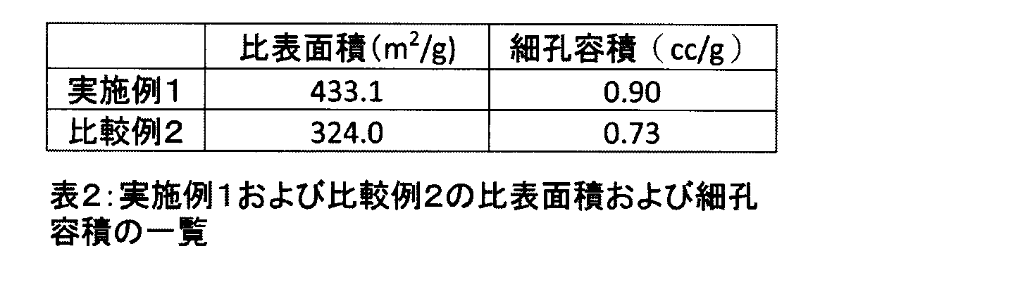
表2によれば、実施例1の生成物の比表面積および細孔容積は、比較例2の生成物のそれよりも大きいことが分かる。特に、本発明の材料が、大きな比表面積を有することにより、高エネルギー密度を達成することを示唆する。
図10は、実施例1および比較例2の生成物の比容量-電圧曲線(CV曲線)を示す図である。
図10(a)および(b)は、それぞれ、掃引速度50mV/sおよび500mV/Sの結果である。図10(a)によれば、実施例1および比較例2の生成物は、理想的な電気二重層キャパシタを表す矩形のCV曲線を示した。しかしながら図10(b)に示されるように、掃引速度が増大すると、実施例1の生成物は、矩形のCV曲線を示したものの、比較例2の生成物は、矩形のCV曲線を示さなかった。このことから、実施例1の生成物は、優れたレート特性を有する電極材料として機能することが確認された。図示しないが、実施例3~5の生成物のCV曲線も、実施例1の生成物のそれと同様の結果を示した。
図11は、実施例1および比較例2の生成物の充放電曲線を示す図である。
図12は、実施例3~5の生成物の充放電曲線を示す図である。
図12は、実施例3~5の生成物の充放電曲線を示す図である。
図11(a)および(b)は、それぞれ、電流密度2A/gおよび20A/gの定電流充放電曲線である。図12は、電流密度20A/gの定電流充放電曲線である。いずれの結果も、生成物は、電気二重層キャパシタに典型的な定電流充放電曲線を示した。詳細には、図11(a)によれば、低電流密度においては、実施例1の生成物の充放電曲線は、比較例2のそれに比べて、わずかながら放電時間が長いものの、実質的に変わらなかった。しかしながら、図11(b)によれば、電流密度が増大すると、実施例1の生成物の充放電曲線は、比較例2のそれに比べて、放電時間が顕著に長くなった。図12によれば、実施例1の生成物と同様に、実施例3~5の生成物も、長い放電時間同様の結果を示した。このことからも、実施例1、3~5の生成物は、優れたレート特性を有する電極材料として機能することが確認された。
図13は、実施例1および比較例2の生成物の比容量の電流密度依存性を示す図である。
実施例1の生成物の比容量は、電流密度に関わらず、実質的に変化しないことが分かった。一方、比較例2の生成物の比容量は、電流密度の増大に伴い、減少した。各電流密度における比容量の値を表3にまとめた。

表3によれば、電流密度0.5A/gにおける、実施例1の生成物の比容量は、135F/gであり、比較例2の生成物のそれ(129F/g)よりもわずかに大きかった。これは、表2を参照して説明したように、実施例1の生成物の比表面積が、比較例2の生成物のそれよりも大きいことに起因する。
さらに、表3によれば、電流密度20A/gにおける、実施例1の生成物の比容量は、114F/gであったが、比較例2の生成物のそれは、68F/gであった。比較例2の生成物の比容量は、129F/g(@0.5A/g)から68F/g(@20A/g)まで減少し、その保持率は、わずか53%であり、極めて低いリテンション特性であった。一方、実施例1の生成物の比容量は、135F/g(@0.5A/g)から114F/g(@20A/g)にわずかに減少したが、その保持率は、85%と高く、高いリテンション特性を示した。このことから、実施例1の生成物を電解質がイオン液体である蓄電デバイスにおける電極として用いた場合、比較例2の生成物に対して、イオン液体の低い導電性および高い粘性にかかわらず、高いレート特性を有し得ることを示唆する。
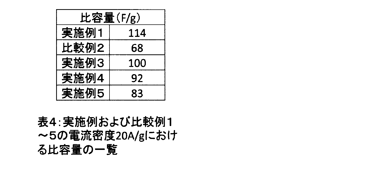
表4に示すように、実施例3~5の生成物も、実施例1の生成物と同様に、高い電流密度においても、高い比容量を有しており、高いリテンション特性を示した。
以上より、本発明の生成物は、イオン液体を含有したRGOが積層した積層体を含む材料であり、イオン液体を電解質とする蓄電デバイスの電極材料として好適であることが確認された。
図14は、実施例1および比較例2の生成物のRagoneプロットを示す図である。
図14によれば、実施例1の生成物のエネルギー密度は、比較例2の生成物のそれに比べて、電力密度の増加によっても、実質的に減少しなかった。例えば、電力密度18kW/kgにおける実施例1の生成物のエネルギー密度は、49Wh/kgであり、比較例2の生成物のそれ(29Wh/kg)よりも顕著に大きかった。図示しないが、実施例3~5の生成物も、実施例1の生成物と同様の傾向を示した。
図15は、実施例1および比較例2の生成物のサイクル特性を示す図である。
実施例1の生成物は、電流密度10A/gにおける繰り返しサイクル2000回後も、92%の高い容量保持率を有し、比較例2の生成物のそれ(82%)よりも高かった。図示しないが、実施例3~5の生成物も、実施例1の生成物と同様の結果を示した。
以上より、本発明の生成物は、イオン液体を電解質とする蓄電デバイスの電極材料として好適であることが確認された。
図16は、実施例1および比較例2の生成物のナイキストプロットを示す図である。
図16によれば、実施例1の生成物のx軸の切片から得られる等価直列抵抗(ESR;4.7Ω)は、比較例2の生成物のそれ(6.1Ω)よりも小さく、実施例1の生成物が、集電体と良好に接触し得ることが分かった。これは、実施例1の生成物が、図5および図6を参照して説明したように、階層状のカーブしたシートからなる多孔構造を有しているため、電荷輸送のための多くの接点が提供されることに基づく。
図16の挿入図に示されるように、半円の直径は、電荷輸送抵抗(Rct)を表しており、電極と電解質との間の界面における電解質のイオンの輸送に関係している。実施例1の生成物のRctは、0.86Ωであり、この値は、比較例2の生成物のRct(3.5Ω)のわずか1/4であった。抵抗が低減すると、イオンの吸脱着を促進するので、電気二重層キャパシタのレート特性が向上する。同様に、実施例3~5の生成物のRctもまた、低い値であった。
図17は、実施例1および比較例2の生成物の規格化比容量の周波数依存性を示す図である。
実施例1および比較例2の生成物の動作周波数f0.5(容量が最大値の50%となる周波数)は、それぞれ、18.60Hzおよび5.75Hzであった。これらの値から求めた実施例1および比較例2の生成物の緩和時定数τ0(=1/f0.5)は、それぞれ、53.6msおよび173.9msであった。図示しないが、実施例3~5の生成物の周波数応答も、比較例2の生成物のそれよりも速いことを確認した。
以上から、本発明の生成物は、イオン液体を含有したRGOが積層した積層体を含む材料であり、本発明の生成物とイオン液体である電解質との間の整合性が向上したことが確認された。
本発明の電極材料を、イオン液体を電解質に用いた蓄電デバイスに用いれば、電極材料のレート特性が向上し、高い出力密度および高いエネルギー密度を達成しつつ素早い充放電を可能にする。このような蓄電デバイスが電気二重層キャパシタであれば、風力発電、電気自動車などに有利である。このような蓄電デバイスがリチウムイオン電池であれば、ノートパソコン、携帯電話等のポータブル電子機器に有利である。
100 電極材料
110 酸化グラフェン(RGO)
120 積層体
130 イオン液体
400 電気二重層キャパシタ
410 正極電極
420 負極伝国
430 電解質
440 セパレータ
450 セル
110 酸化グラフェン(RGO)
120 積層体
130 イオン液体
400 電気二重層キャパシタ
410 正極電極
420 負極伝国
430 電解質
440 セパレータ
450 セル
Claims (19)
- 還元された酸化グラフェンが積層した積層体を含む電極材料であって、
前記積層体は、前記還元された酸化グラフェン間にイオン液体を含有する、電極材料。 - 還元された酸化グラフェンに対する含有されるイオン液体との重量比は、0.01以上1.00以下の範囲である、請求項1に記載の電極材料。
- 還元された酸化グラフェンに対する含有されるイオン液体との重量比は、0.02以上0.60以下の範囲である、請求項2に記載の電極材料。
- 前記積層体の比表面積は、350m2/g以上500m2/g以下の範囲である、請求項1に記載の電極材料。
- 前記積層体の比表面積は、420m2/g以上450m2/g以下の範囲である、請求項4に記載の電極材料。
- 前記積層体の細孔容積は、0.75cc/g以上1.5cc/g以下の範囲である、請求項1に記載の電極材料。
- 前記積層体の細孔容積は、0.85cc/g以上0.95cc/g以下の範囲である、請求項6に記載の電極材料。
- 前記イオン液体は、1-エチル-3-メチルイミダゾリウムテトラフルオロボレート(EMIMBF4)、1-エチル-3-メチルイミダゾリウム-ビス(フルオロスルホニル)イミド(EMIFSI)、1-エチル-3-メチルイミダゾリウム-ビス(トリフルオロメタンスルホニル)イミド(EMITFSI)、1-ブチル-3-メチルイミダゾリウム-ビス(トリフルオロメタンスルホニル)イミド(BMITFSI)、1-ヘキシル-3-メチルイミダゾリウムテトラフルオロボレート(HMIBF4)、1-ヘキシル-3-メチルイミダゾリウム-ビス(トリフルオロメタンスルホニル)イミド(HMITFSI)、1-エチル-3-メチルイミダゾリウム-フルオロハイドロジェネート(EMI(FH)2.3F)、N,N-ジエチル-N-メチル-N-(2-メトキシエチル)-テトラフルオロボレート(DEMEBF4)、N,N-ジエチル-N-メチル-N-(2-メトキシエチル)-ビス(トリフルオロメタンスルホニル)イミド(DEMETFSI)、N-メチル-N-プロピルピペリジニウム-ビス(トリフルオロメタンスルホニル)イミド(PP13TFSI)、トリエチルスルホニウム-ビス(トリフルオロメタンスルホニル)イミド(TESTFSI)、N-メチル-Nプロピルピロリジニウム-ビス(トリフルオロメタンスルホニル)イミド(P13TFSI)、トリエチルオクチルホスホニウム-ビス(トリフルオロメタンスルホニル)イミド(P2228TFSI)、N-メチル-メトキシメチルピロリジニウム-テトラフルオロボレート(C13BF4)、リチウム-ビス(フルオロスルホニル)イミド(LiFSI)、および、リチウム-ビス(トリフルオロメタンスルホニル)イミド(LiTFSI)からなる群から少なくとも1つ選択される、請求項1に記載の電極材料。
- 前記積層体は、2nm以上6nm以下の範囲の直径を有するメソ細孔、および、50nm以上の直径を有するマクロ細孔を有する、請求項1に記載の電極材料。
- 前記積層体は、電流密度20A/gにおいて、80F/g以上140F/g以下の範囲の比容量を有する、請求項1に記載の電極材料。
- 請求項1~10のいずれかに記載の電極材料を製造する方法であって、
極性溶媒に酸化グラフェンおよびイオン液体を添加した懸濁液を調製するステップと、
前記懸濁液に還元剤を添加し、還流するステップと
を包含する、方法。 - 前記調製するステップにおいて、前記酸化グラフェンに対するイオン液体の重量比は、0.005以上0.5以下である、請求項11に記載の方法。
- 前記調製するステップにおいて、前記酸化グラフェンに対するイオン液体の重量比は、0.01以上0.3以下である、請求項12に記載の方法。
- 前記極性溶媒は、水、ジメチルスルホキシド(DMSO)、N,N-ジメチルスルホアミド(DMF)およびエタノールからなる群から選択される、請求項11に記載の方法。
- 前記イオン液体は、1-エチル-3-メチルイミダゾリウムテトラフルオロボレート(EMIBF4)、1-エチル-3-メチルイミダゾリウム-ビス(フルオロスルホニル)イミド(EMIFSI)、1-エチル-3-メチルイミダゾリウム-ビス(トリフルオロメタンスルホニル)イミド(EMITFSI)、1-ブチル-3-メチルイミダゾリウム-ビス(トリフルオロメタンスルホニル)イミド(BMITFSI)、1-ヘキシル-3-メチルイミダゾリウムテトラフルオロボレート(HMIBF4)、1-ヘキシル-3-メチルイミダゾリウム-ビス(トリフルオロメタンスルホニル)イミド(HMITFSI)、1-エチル-3-メチルイミダゾリウム-フルオロハイドロジェネート(EMI(FH)2.3F)、N,N-ジエチル-N-メチル-N-(2-メトキシエチル)-テトラフルオロボレート(DEMEBF4)、N,N-ジエチル-N-メチル-N-(2-メトキシエチル)-ビス(トリフルオロメタンスルホニル)イミド(DEMETFSI)、N-メチル-N-プロピルピペリジニウム-ビス(トリフルオロメタンスルホニル)イミド(PP13TFSI)、トリエチルスルホニウム-ビス(トリフルオロメタンスルホニル)イミド(TESTFSI)、N-メチル-Nプロピルピロリジニウム-ビス(トリフルオロメタンスルホニル)イミド(P13TFSI)、トリエチルオクチルホスホニウム-ビス(トリフルオロメタンスルホニル)イミド(P2228TFSI)、N-メチル-メトキシメチルピロリジニウム-テトラフルオロボレート(C13BF4)、リチウム-ビス(フルオロスルホニル)イミド(LiFSI)、および、リチウム-ビス(トリフルオロメタンスルホニル)イミド(LiTFSI)からなる群から少なくとも1つ選択される、請求項11に記載の方法。
- 前記還元剤は、ヒドラジン、ジメチルヒドラジン、アスコルビン酸、ヒドロキノン、水素化硼素ナトリウム(NaBH4)、テトラブチルアンモニウムブロマイド(TBAB)、LiAlH4、エチレングリコール、ポリエチレングリコール、ヨウ化水素、および、N,N-ジエチルヒドロキシルアミンからなる群から少なくとも1つ選択される、請求項11に記載の方法。
- 電極と、電解質とを備えた蓄電デバイスであって、
前記電極は、請求項1~10のいずれかに記載の電極材料からなる、蓄電デバイス。 - 前記蓄電デバイスは、電気二重層キャパシタであり、
前記電解質は、イオン液体であり、
前記イオン液体は、前記電極材料中に含有されるイオン液体と同じである、請求項17に記載の蓄電デバイス。 - 前記蓄電デバイスは、リチウムイオン電池であり、
前記電解質は、リチウムを含有するイオン液体であり、
前記リチウムを含有するイオン液体は、前記電極材料中に含有されるイオン液体と同じである、請求項17に記載の蓄電デバイス。
Priority Applications (1)
| Application Number | Priority Date | Filing Date | Title |
|---|---|---|---|
| JP2017520672A JP6455861B2 (ja) | 2015-05-28 | 2016-05-19 | 電極材料、その製造方法、および、それを用いた蓄電デバイス |
Applications Claiming Priority (2)
| Application Number | Priority Date | Filing Date | Title |
|---|---|---|---|
| JP2015109185 | 2015-05-28 | ||
| JP2015-109185 | 2015-05-28 |
Publications (1)
| Publication Number | Publication Date |
|---|---|
| WO2016190225A1 true WO2016190225A1 (ja) | 2016-12-01 |
Family
ID=57393849
Family Applications (1)
| Application Number | Title | Priority Date | Filing Date |
|---|---|---|---|
| PCT/JP2016/064937 Ceased WO2016190225A1 (ja) | 2015-05-28 | 2016-05-19 | 電極材料、その製造方法、および、それを用いた蓄電デバイス |
Country Status (2)
| Country | Link |
|---|---|
| JP (1) | JP6455861B2 (ja) |
| WO (1) | WO2016190225A1 (ja) |
Cited By (13)
| Publication number | Priority date | Publication date | Assignee | Title |
|---|---|---|---|---|
| JP2017050109A (ja) * | 2015-08-31 | 2017-03-09 | トヨタ自動車株式会社 | 負極活物質粒子及び負極活物質粒子の製造方法 |
| CN108428565A (zh) * | 2017-02-13 | 2018-08-21 | 中国科学院宁波材料技术与工程研究所 | 二硫化钨/氧化石墨烯复合材料、其制备方法与应用 |
| JP2019507081A (ja) * | 2015-12-22 | 2019-03-14 | ザ リージェンツ オブ ザ ユニバーシティ オブ カリフォルニア | セル式グラフェン膜 |
| US11004618B2 (en) | 2012-03-05 | 2021-05-11 | The Regents Of The University Of California | Capacitor with electrodes made of an interconnected corrugated carbon-based network |
| US11062855B2 (en) | 2016-03-23 | 2021-07-13 | The Regents Of The University Of California | Devices and methods for high voltage and solar applications |
| US11097951B2 (en) | 2016-06-24 | 2021-08-24 | The Regents Of The University Of California | Production of carbon-based oxide and reduced carbon-based oxide on a large scale |
| US11133134B2 (en) | 2017-07-14 | 2021-09-28 | The Regents Of The University Of California | Simple route to highly conductive porous graphene from carbon nanodots for supercapacitor applications |
| US11397173B2 (en) | 2011-12-21 | 2022-07-26 | The Regents Of The University Of California | Interconnected corrugated carbon-based network |
| US11569538B2 (en) | 2014-06-16 | 2023-01-31 | The Regents Of The University Of California | Hybrid electrochemical cell |
| JP2023069303A (ja) * | 2021-11-05 | 2023-05-18 | パナソニックIpマネジメント株式会社 | キャパシタ |
| US11791453B2 (en) | 2016-08-31 | 2023-10-17 | The Regents Of The University Of California | Devices comprising carbon-based material and fabrication thereof |
| US11810716B2 (en) | 2014-11-18 | 2023-11-07 | The Regents Of The University Of California | Porous interconnected corrugated carbon-based network (ICCN) composite |
| US11842850B2 (en) | 2016-01-22 | 2023-12-12 | The Regents Of The University Of California | High-voltage devices |
Citations (3)
| Publication number | Priority date | Publication date | Assignee | Title |
|---|---|---|---|---|
| JP2005347611A (ja) * | 2004-06-04 | 2005-12-15 | Honda Motor Co Ltd | 電気二重層キャパシタ |
| JP2013514963A (ja) * | 2009-12-22 | 2013-05-02 | スー・クワンスック | グラフェン分散液およびグラフェン−イオン性液体高分子複合物 |
| JP2014240330A (ja) * | 2013-05-16 | 2014-12-25 | 独立行政法人物質・材料研究機構 | グラフェン球状中空体の作成方法、グラフェン球状中空体、グラフェン球状中空体集積電極及びグラフェン球状中空体集積キャパシター |
Family Cites Families (1)
| Publication number | Priority date | Publication date | Assignee | Title |
|---|---|---|---|---|
| JP2014225508A (ja) * | 2013-05-15 | 2014-12-04 | 住友電気工業株式会社 | 蓄電デバイス用電極、蓄電デバイスおよび蓄電デバイス用電極の製造方法 |
-
2016
- 2016-05-19 WO PCT/JP2016/064937 patent/WO2016190225A1/ja not_active Ceased
- 2016-05-19 JP JP2017520672A patent/JP6455861B2/ja active Active
Patent Citations (3)
| Publication number | Priority date | Publication date | Assignee | Title |
|---|---|---|---|---|
| JP2005347611A (ja) * | 2004-06-04 | 2005-12-15 | Honda Motor Co Ltd | 電気二重層キャパシタ |
| JP2013514963A (ja) * | 2009-12-22 | 2013-05-02 | スー・クワンスック | グラフェン分散液およびグラフェン−イオン性液体高分子複合物 |
| JP2014240330A (ja) * | 2013-05-16 | 2014-12-25 | 独立行政法人物質・材料研究機構 | グラフェン球状中空体の作成方法、グラフェン球状中空体、グラフェン球状中空体集積電極及びグラフェン球状中空体集積キャパシター |
Cited By (22)
| Publication number | Priority date | Publication date | Assignee | Title |
|---|---|---|---|---|
| US11397173B2 (en) | 2011-12-21 | 2022-07-26 | The Regents Of The University Of California | Interconnected corrugated carbon-based network |
| US11257632B2 (en) | 2012-03-05 | 2022-02-22 | The Regents Of The University Of California | Capacitor with electrodes made of an interconnected corrugated carbon-based network |
| US11915870B2 (en) | 2012-03-05 | 2024-02-27 | The Regents Of The University Of California | Capacitor with electrodes made of an interconnected corrugated carbon-based network |
| US11004618B2 (en) | 2012-03-05 | 2021-05-11 | The Regents Of The University Of California | Capacitor with electrodes made of an interconnected corrugated carbon-based network |
| US11569538B2 (en) | 2014-06-16 | 2023-01-31 | The Regents Of The University Of California | Hybrid electrochemical cell |
| US11810716B2 (en) | 2014-11-18 | 2023-11-07 | The Regents Of The University Of California | Porous interconnected corrugated carbon-based network (ICCN) composite |
| DE102016115875B4 (de) * | 2015-08-31 | 2021-01-28 | Toyota Jidosha Kabushiki Kaisha | Verfahren zum Herstellen eines Anodenaktivmaterialteilchens, einer Anode sowie einer Lithiumbatterie |
| JP2017050109A (ja) * | 2015-08-31 | 2017-03-09 | トヨタ自動車株式会社 | 負極活物質粒子及び負極活物質粒子の製造方法 |
| JP7176735B2 (ja) | 2015-12-22 | 2022-11-22 | ザ リージェンツ オブ ザ ユニバーシティ オブ カリフォルニア | セル式グラフェン膜 |
| US11891539B2 (en) | 2015-12-22 | 2024-02-06 | The Regents Of The University Of California | Cellular graphene films |
| US11118073B2 (en) | 2015-12-22 | 2021-09-14 | The Regents Of The University Of California | Cellular graphene films |
| JP2019507081A (ja) * | 2015-12-22 | 2019-03-14 | ザ リージェンツ オブ ザ ユニバーシティ オブ カリフォルニア | セル式グラフェン膜 |
| US11842850B2 (en) | 2016-01-22 | 2023-12-12 | The Regents Of The University Of California | High-voltage devices |
| US11062855B2 (en) | 2016-03-23 | 2021-07-13 | The Regents Of The University Of California | Devices and methods for high voltage and solar applications |
| US11961667B2 (en) | 2016-03-23 | 2024-04-16 | The Regents Of The University Of California | Devices and methods for high voltage and solar applications |
| US11097951B2 (en) | 2016-06-24 | 2021-08-24 | The Regents Of The University Of California | Production of carbon-based oxide and reduced carbon-based oxide on a large scale |
| US11791453B2 (en) | 2016-08-31 | 2023-10-17 | The Regents Of The University Of California | Devices comprising carbon-based material and fabrication thereof |
| CN108428565A (zh) * | 2017-02-13 | 2018-08-21 | 中国科学院宁波材料技术与工程研究所 | 二硫化钨/氧化石墨烯复合材料、其制备方法与应用 |
| CN108428565B (zh) * | 2017-02-13 | 2019-09-27 | 中国科学院宁波材料技术与工程研究所 | 二硫化钨/氧化石墨烯复合材料、其制备方法与应用 |
| US11133134B2 (en) | 2017-07-14 | 2021-09-28 | The Regents Of The University Of California | Simple route to highly conductive porous graphene from carbon nanodots for supercapacitor applications |
| US12283424B2 (en) | 2017-07-14 | 2025-04-22 | The Regents Of The University Of California | Simple route to highly conductive porous graphene from carbon nanodots for supercapacitor applications |
| JP2023069303A (ja) * | 2021-11-05 | 2023-05-18 | パナソニックIpマネジメント株式会社 | キャパシタ |
Also Published As
| Publication number | Publication date |
|---|---|
| JPWO2016190225A1 (ja) | 2018-02-01 |
| JP6455861B2 (ja) | 2019-01-23 |
Similar Documents
| Publication | Publication Date | Title |
|---|---|---|
| JP6455861B2 (ja) | 電極材料、その製造方法、および、それを用いた蓄電デバイス | |
| Shabangoli et al. | Nile blue functionalized graphene aerogel as a pseudocapacitive negative electrode material across the full pH range | |
| Ji et al. | Nanoporous Ni (OH) 2 thin film on 3D ultrathin-graphite foam for asymmetric supercapacitor | |
| Farisabadi et al. | Controlled thermolysis of MIL-101 (Fe, Cr) for synthesis of FexOy/porous carbon as negative electrode and Cr2O3/porous carbon as positive electrode of supercapacitor | |
| Hao et al. | B/N co-doped carbon nanosphere frameworks as high-performance electrodes for supercapacitors | |
| Zhang et al. | ZIF-derived porous carbon: a promising supercapacitor electrode material | |
| Lin et al. | A novel core–shell multi-walled carbon nanotube@ graphene oxide nanoribbon heterostructure as a potential supercapacitor material | |
| Chen et al. | Rich nitrogen-doped ordered mesoporous phenolic resin-based carbon for supercapacitors | |
| Yu et al. | Controllable growth of polyaniline nanowire arrays on hierarchical macro/mesoporous graphene foams for high-performance flexible supercapacitors | |
| Wang et al. | Asymmetric supercapacitors based on nano-architectured nickel oxide/graphene foam and hierarchical porous nitrogen-doped carbon nanotubes with ultrahigh-rate performance | |
| Ghosh et al. | α MnMoO4/graphene hybrid composite: high energy density supercapacitor electrode material | |
| Joseph et al. | Metallic MoS2 grown on porous g-C3N4 as an efficient electrode material for supercapattery application | |
| Sassin et al. | Electroless deposition of conformal nanoscale iron oxide on carbon nanoarchitectures for electrochemical charge storage | |
| Guo et al. | Tailoring kirkendall effect of the KCu7S4 microwires towards CuO@ MnO2 core-shell nanostructures for supercapacitors | |
| Li et al. | Graphene@ hierarchical meso-/microporous carbon for ultrahigh energy density lithium-ion capacitors | |
| Kim et al. | Ionic liquid-assisted microwave reduction of graphite oxide for supercapacitors | |
| CN105900200A (zh) | 基于三维石墨烯框架的高性能超级电容器 | |
| Tang et al. | Enhanced energy density of asymmetric supercapacitors via optimizing negative electrode material and mass ratio of negative/positive electrodes | |
| CN105393321A (zh) | 蓄电装置用电极、蓄电装置以及蓄电装置用电极的制造方法 | |
| Jain et al. | Experimental studies on high-performance supercapacitor based on nanogel polymer electrolyte with treated activated charcoal | |
| Yang et al. | Facile synthesis of reduced graphene oxide/tungsten disulfide/tungsten oxide nanohybrids for high performance supercapacitor with excellent rate capability | |
| Barmi et al. | Role of polymeric surfactant in the synthesis of cobalt molybdate nanospheres for hybrid capacitor applications | |
| Aghazadeh et al. | In situ growth of Ni (OH) 2-porous nitrogen-doped graphene composite onto Ni foam support as advanced electrochemical supercapacitors materials | |
| Xu et al. | KOH‐assisted microwave post‐treatment of activated carbon for efficient symmetrical double‐layer capacitors | |
| Phattharasupakun et al. | High-performance supercapacitors of carboxylate-modified hollow carbon nanospheres coated on flexible carbon fibre paper: Effects of oxygen-containing group contents, electrolytes and operating temperature |
Legal Events
| Date | Code | Title | Description |
|---|---|---|---|
| 121 | Ep: the epo has been informed by wipo that ep was designated in this application |
Ref document number: 16799931 Country of ref document: EP Kind code of ref document: A1 |
|
| ENP | Entry into the national phase |
Ref document number: 2017520672 Country of ref document: JP Kind code of ref document: A |
|
| NENP | Non-entry into the national phase |
Ref country code: DE |
|
| 122 | Ep: pct application non-entry in european phase |
Ref document number: 16799931 Country of ref document: EP Kind code of ref document: A1 |