WO2016190132A1 - Système, procédé, et programme de gestion d'un dispositif de transmission de puissance - Google Patents
Système, procédé, et programme de gestion d'un dispositif de transmission de puissance Download PDFInfo
- Publication number
- WO2016190132A1 WO2016190132A1 PCT/JP2016/064309 JP2016064309W WO2016190132A1 WO 2016190132 A1 WO2016190132 A1 WO 2016190132A1 JP 2016064309 W JP2016064309 W JP 2016064309W WO 2016190132 A1 WO2016190132 A1 WO 2016190132A1
- Authority
- WO
- WIPO (PCT)
- Prior art keywords
- power transmission
- level
- transmission device
- power
- unit
- Prior art date
Links
Images


Classifications
-
- H—ELECTRICITY
- H02—GENERATION; CONVERSION OR DISTRIBUTION OF ELECTRIC POWER
- H02J—CIRCUIT ARRANGEMENTS OR SYSTEMS FOR SUPPLYING OR DISTRIBUTING ELECTRIC POWER; SYSTEMS FOR STORING ELECTRIC ENERGY
- H02J50/00—Circuit arrangements or systems for wireless supply or distribution of electric power
- H02J50/80—Circuit arrangements or systems for wireless supply or distribution of electric power involving the exchange of data, concerning supply or distribution of electric power, between transmitting devices and receiving devices
-
- B—PERFORMING OPERATIONS; TRANSPORTING
- B60—VEHICLES IN GENERAL
- B60L—PROPULSION OF ELECTRICALLY-PROPELLED VEHICLES; SUPPLYING ELECTRIC POWER FOR AUXILIARY EQUIPMENT OF ELECTRICALLY-PROPELLED VEHICLES; ELECTRODYNAMIC BRAKE SYSTEMS FOR VEHICLES IN GENERAL; MAGNETIC SUSPENSION OR LEVITATION FOR VEHICLES; MONITORING OPERATING VARIABLES OF ELECTRICALLY-PROPELLED VEHICLES; ELECTRIC SAFETY DEVICES FOR ELECTRICALLY-PROPELLED VEHICLES
- B60L50/00—Electric propulsion with power supplied within the vehicle
- B60L50/50—Electric propulsion with power supplied within the vehicle using propulsion power supplied by batteries or fuel cells
- B60L50/60—Electric propulsion with power supplied within the vehicle using propulsion power supplied by batteries or fuel cells using power supplied by batteries
-
- B—PERFORMING OPERATIONS; TRANSPORTING
- B60—VEHICLES IN GENERAL
- B60L—PROPULSION OF ELECTRICALLY-PROPELLED VEHICLES; SUPPLYING ELECTRIC POWER FOR AUXILIARY EQUIPMENT OF ELECTRICALLY-PROPELLED VEHICLES; ELECTRODYNAMIC BRAKE SYSTEMS FOR VEHICLES IN GENERAL; MAGNETIC SUSPENSION OR LEVITATION FOR VEHICLES; MONITORING OPERATING VARIABLES OF ELECTRICALLY-PROPELLED VEHICLES; ELECTRIC SAFETY DEVICES FOR ELECTRICALLY-PROPELLED VEHICLES
- B60L53/00—Methods of charging batteries, specially adapted for electric vehicles; Charging stations or on-board charging equipment therefor; Exchange of energy storage elements in electric vehicles
- B60L53/30—Constructional details of charging stations
-
- B—PERFORMING OPERATIONS; TRANSPORTING
- B60—VEHICLES IN GENERAL
- B60L—PROPULSION OF ELECTRICALLY-PROPELLED VEHICLES; SUPPLYING ELECTRIC POWER FOR AUXILIARY EQUIPMENT OF ELECTRICALLY-PROPELLED VEHICLES; ELECTRODYNAMIC BRAKE SYSTEMS FOR VEHICLES IN GENERAL; MAGNETIC SUSPENSION OR LEVITATION FOR VEHICLES; MONITORING OPERATING VARIABLES OF ELECTRICALLY-PROPELLED VEHICLES; ELECTRIC SAFETY DEVICES FOR ELECTRICALLY-PROPELLED VEHICLES
- B60L53/00—Methods of charging batteries, specially adapted for electric vehicles; Charging stations or on-board charging equipment therefor; Exchange of energy storage elements in electric vehicles
- B60L53/60—Monitoring or controlling charging stations
- B60L53/63—Monitoring or controlling charging stations in response to network capacity
-
- B—PERFORMING OPERATIONS; TRANSPORTING
- B60—VEHICLES IN GENERAL
- B60L—PROPULSION OF ELECTRICALLY-PROPELLED VEHICLES; SUPPLYING ELECTRIC POWER FOR AUXILIARY EQUIPMENT OF ELECTRICALLY-PROPELLED VEHICLES; ELECTRODYNAMIC BRAKE SYSTEMS FOR VEHICLES IN GENERAL; MAGNETIC SUSPENSION OR LEVITATION FOR VEHICLES; MONITORING OPERATING VARIABLES OF ELECTRICALLY-PROPELLED VEHICLES; ELECTRIC SAFETY DEVICES FOR ELECTRICALLY-PROPELLED VEHICLES
- B60L53/00—Methods of charging batteries, specially adapted for electric vehicles; Charging stations or on-board charging equipment therefor; Exchange of energy storage elements in electric vehicles
- B60L53/60—Monitoring or controlling charging stations
- B60L53/64—Optimising energy costs, e.g. responding to electricity rates
-
- B—PERFORMING OPERATIONS; TRANSPORTING
- B60—VEHICLES IN GENERAL
- B60L—PROPULSION OF ELECTRICALLY-PROPELLED VEHICLES; SUPPLYING ELECTRIC POWER FOR AUXILIARY EQUIPMENT OF ELECTRICALLY-PROPELLED VEHICLES; ELECTRODYNAMIC BRAKE SYSTEMS FOR VEHICLES IN GENERAL; MAGNETIC SUSPENSION OR LEVITATION FOR VEHICLES; MONITORING OPERATING VARIABLES OF ELECTRICALLY-PROPELLED VEHICLES; ELECTRIC SAFETY DEVICES FOR ELECTRICALLY-PROPELLED VEHICLES
- B60L53/00—Methods of charging batteries, specially adapted for electric vehicles; Charging stations or on-board charging equipment therefor; Exchange of energy storage elements in electric vehicles
- B60L53/60—Monitoring or controlling charging stations
- B60L53/66—Data transfer between charging stations and vehicles
- B60L53/665—Methods related to measuring, billing or payment
-
- H—ELECTRICITY
- H02—GENERATION; CONVERSION OR DISTRIBUTION OF ELECTRIC POWER
- H02J—CIRCUIT ARRANGEMENTS OR SYSTEMS FOR SUPPLYING OR DISTRIBUTING ELECTRIC POWER; SYSTEMS FOR STORING ELECTRIC ENERGY
- H02J50/00—Circuit arrangements or systems for wireless supply or distribution of electric power
- H02J50/10—Circuit arrangements or systems for wireless supply or distribution of electric power using inductive coupling
-
- H—ELECTRICITY
- H02—GENERATION; CONVERSION OR DISTRIBUTION OF ELECTRIC POWER
- H02J—CIRCUIT ARRANGEMENTS OR SYSTEMS FOR SUPPLYING OR DISTRIBUTING ELECTRIC POWER; SYSTEMS FOR STORING ELECTRIC ENERGY
- H02J7/00—Circuit arrangements for charging or depolarising batteries or for supplying loads from batteries
- H02J7/02—Circuit arrangements for charging or depolarising batteries or for supplying loads from batteries for charging batteries from ac mains by converters
- H02J7/04—Regulation of charging current or voltage
-
- H—ELECTRICITY
- H02—GENERATION; CONVERSION OR DISTRIBUTION OF ELECTRIC POWER
- H02J—CIRCUIT ARRANGEMENTS OR SYSTEMS FOR SUPPLYING OR DISTRIBUTING ELECTRIC POWER; SYSTEMS FOR STORING ELECTRIC ENERGY
- H02J2310/00—The network for supplying or distributing electric power characterised by its spatial reach or by the load
- H02J2310/10—The network having a local or delimited stationary reach
- H02J2310/20—The network being internal to a load
- H02J2310/22—The load being a portable electronic device
-
- H—ELECTRICITY
- H02—GENERATION; CONVERSION OR DISTRIBUTION OF ELECTRIC POWER
- H02J—CIRCUIT ARRANGEMENTS OR SYSTEMS FOR SUPPLYING OR DISTRIBUTING ELECTRIC POWER; SYSTEMS FOR STORING ELECTRIC ENERGY
- H02J2310/00—The network for supplying or distributing electric power characterised by its spatial reach or by the load
- H02J2310/40—The network being an on-board power network, i.e. within a vehicle
- H02J2310/48—The network being an on-board power network, i.e. within a vehicle for electric vehicles [EV] or hybrid vehicles [HEV]
-
- H—ELECTRICITY
- H02—GENERATION; CONVERSION OR DISTRIBUTION OF ELECTRIC POWER
- H02J—CIRCUIT ARRANGEMENTS OR SYSTEMS FOR SUPPLYING OR DISTRIBUTING ELECTRIC POWER; SYSTEMS FOR STORING ELECTRIC ENERGY
- H02J7/00—Circuit arrangements for charging or depolarising batteries or for supplying loads from batteries
- H02J7/00032—Circuit arrangements for charging or depolarising batteries or for supplying loads from batteries characterised by data exchange
- H02J7/00034—Charger exchanging data with an electronic device, i.e. telephone, whose internal battery is under charge
-
- H—ELECTRICITY
- H02—GENERATION; CONVERSION OR DISTRIBUTION OF ELECTRIC POWER
- H02J—CIRCUIT ARRANGEMENTS OR SYSTEMS FOR SUPPLYING OR DISTRIBUTING ELECTRIC POWER; SYSTEMS FOR STORING ELECTRIC ENERGY
- H02J7/00—Circuit arrangements for charging or depolarising batteries or for supplying loads from batteries
- H02J7/0029—Circuit arrangements for charging or depolarising batteries or for supplying loads from batteries with safety or protection devices or circuits
- H02J7/00304—Overcurrent protection
-
- H—ELECTRICITY
- H02—GENERATION; CONVERSION OR DISTRIBUTION OF ELECTRIC POWER
- H02J—CIRCUIT ARRANGEMENTS OR SYSTEMS FOR SUPPLYING OR DISTRIBUTING ELECTRIC POWER; SYSTEMS FOR STORING ELECTRIC ENERGY
- H02J7/00—Circuit arrangements for charging or depolarising batteries or for supplying loads from batteries
- H02J7/0047—Circuit arrangements for charging or depolarising batteries or for supplying loads from batteries with monitoring or indicating devices or circuits
- H02J7/0048—Detection of remaining charge capacity or state of charge [SOC]
-
- H—ELECTRICITY
- H02—GENERATION; CONVERSION OR DISTRIBUTION OF ELECTRIC POWER
- H02J—CIRCUIT ARRANGEMENTS OR SYSTEMS FOR SUPPLYING OR DISTRIBUTING ELECTRIC POWER; SYSTEMS FOR STORING ELECTRIC ENERGY
- H02J7/00—Circuit arrangements for charging or depolarising batteries or for supplying loads from batteries
- H02J7/007—Regulation of charging or discharging current or voltage
- H02J7/007188—Regulation of charging or discharging current or voltage the charge cycle being controlled or terminated in response to non-electric parameters
- H02J7/007192—Regulation of charging or discharging current or voltage the charge cycle being controlled or terminated in response to non-electric parameters in response to temperature
-
- Y—GENERAL TAGGING OF NEW TECHNOLOGICAL DEVELOPMENTS; GENERAL TAGGING OF CROSS-SECTIONAL TECHNOLOGIES SPANNING OVER SEVERAL SECTIONS OF THE IPC; TECHNICAL SUBJECTS COVERED BY FORMER USPC CROSS-REFERENCE ART COLLECTIONS [XRACs] AND DIGESTS
- Y02—TECHNOLOGIES OR APPLICATIONS FOR MITIGATION OR ADAPTATION AGAINST CLIMATE CHANGE
- Y02E—REDUCTION OF GREENHOUSE GAS [GHG] EMISSIONS, RELATED TO ENERGY GENERATION, TRANSMISSION OR DISTRIBUTION
- Y02E60/00—Enabling technologies; Technologies with a potential or indirect contribution to GHG emissions mitigation
-
- Y—GENERAL TAGGING OF NEW TECHNOLOGICAL DEVELOPMENTS; GENERAL TAGGING OF CROSS-SECTIONAL TECHNOLOGIES SPANNING OVER SEVERAL SECTIONS OF THE IPC; TECHNICAL SUBJECTS COVERED BY FORMER USPC CROSS-REFERENCE ART COLLECTIONS [XRACs] AND DIGESTS
- Y02—TECHNOLOGIES OR APPLICATIONS FOR MITIGATION OR ADAPTATION AGAINST CLIMATE CHANGE
- Y02T—CLIMATE CHANGE MITIGATION TECHNOLOGIES RELATED TO TRANSPORTATION
- Y02T10/00—Road transport of goods or passengers
- Y02T10/60—Other road transportation technologies with climate change mitigation effect
- Y02T10/70—Energy storage systems for electromobility, e.g. batteries
-
- Y—GENERAL TAGGING OF NEW TECHNOLOGICAL DEVELOPMENTS; GENERAL TAGGING OF CROSS-SECTIONAL TECHNOLOGIES SPANNING OVER SEVERAL SECTIONS OF THE IPC; TECHNICAL SUBJECTS COVERED BY FORMER USPC CROSS-REFERENCE ART COLLECTIONS [XRACs] AND DIGESTS
- Y02—TECHNOLOGIES OR APPLICATIONS FOR MITIGATION OR ADAPTATION AGAINST CLIMATE CHANGE
- Y02T—CLIMATE CHANGE MITIGATION TECHNOLOGIES RELATED TO TRANSPORTATION
- Y02T90/00—Enabling technologies or technologies with a potential or indirect contribution to GHG emissions mitigation
- Y02T90/10—Technologies relating to charging of electric vehicles
- Y02T90/16—Information or communication technologies improving the operation of electric vehicles
- Y02T90/167—Systems integrating technologies related to power network operation and communication or information technologies for supporting the interoperability of electric or hybrid vehicles, i.e. smartgrids as interface for battery charging of electric vehicles [EV] or hybrid vehicles [HEV]
-
- Y—GENERAL TAGGING OF NEW TECHNOLOGICAL DEVELOPMENTS; GENERAL TAGGING OF CROSS-SECTIONAL TECHNOLOGIES SPANNING OVER SEVERAL SECTIONS OF THE IPC; TECHNICAL SUBJECTS COVERED BY FORMER USPC CROSS-REFERENCE ART COLLECTIONS [XRACs] AND DIGESTS
- Y04—INFORMATION OR COMMUNICATION TECHNOLOGIES HAVING AN IMPACT ON OTHER TECHNOLOGY AREAS
- Y04S—SYSTEMS INTEGRATING TECHNOLOGIES RELATED TO POWER NETWORK OPERATION, COMMUNICATION OR INFORMATION TECHNOLOGIES FOR IMPROVING THE ELECTRICAL POWER GENERATION, TRANSMISSION, DISTRIBUTION, MANAGEMENT OR USAGE, i.e. SMART GRIDS
- Y04S10/00—Systems supporting electrical power generation, transmission or distribution
- Y04S10/12—Monitoring or controlling equipment for energy generation units, e.g. distributed energy generation [DER] or load-side generation
- Y04S10/126—Monitoring or controlling equipment for energy generation units, e.g. distributed energy generation [DER] or load-side generation the energy generation units being or involving electric vehicles [EV] or hybrid vehicles [HEV], i.e. power aggregation of EV or HEV, vehicle to grid arrangements [V2G]
-
- Y—GENERAL TAGGING OF NEW TECHNOLOGICAL DEVELOPMENTS; GENERAL TAGGING OF CROSS-SECTIONAL TECHNOLOGIES SPANNING OVER SEVERAL SECTIONS OF THE IPC; TECHNICAL SUBJECTS COVERED BY FORMER USPC CROSS-REFERENCE ART COLLECTIONS [XRACs] AND DIGESTS
- Y04—INFORMATION OR COMMUNICATION TECHNOLOGIES HAVING AN IMPACT ON OTHER TECHNOLOGY AREAS
- Y04S—SYSTEMS INTEGRATING TECHNOLOGIES RELATED TO POWER NETWORK OPERATION, COMMUNICATION OR INFORMATION TECHNOLOGIES FOR IMPROVING THE ELECTRICAL POWER GENERATION, TRANSMISSION, DISTRIBUTION, MANAGEMENT OR USAGE, i.e. SMART GRIDS
- Y04S30/00—Systems supporting specific end-user applications in the sector of transportation
- Y04S30/10—Systems supporting the interoperability of electric or hybrid vehicles
- Y04S30/14—Details associated with the interoperability, e.g. vehicle recognition, authentication, identification or billing
Definitions
- the present disclosure relates to a system, a method, and a program for managing a power transmission device.
- This application is based on Japanese Patent Application No. 2015-105345 filed on May 25, 2015, and claims the benefit of priority thereto, the entire contents of which are referred to Is incorporated herein by reference.
- a mobile body for example, an electric vehicle
- a rechargeable battery as at least a part of a power source
- Such a mobile body needs to receive power at the charging station when the remaining amount of the battery decreases.
- a mechanism for managing the state of a power transmission device that supplies power to a moving body is known.
- Patent Document 1 describes a non-contact power feeding device that can detect an abnormality.
- the detection unit of the non-contact power feeding device detects the phase difference between the output voltage and the output current output from the power supply main circuit, and the power supply controller determines that the phase difference is outside the specific range.
- the notification device is used to notify that there is an abnormality.
- Patent Document 2 describes a power feeding device including a warning device. Specifically, the power transmission ECU determines whether or not the primary resonance coil is abnormal based on a signal indicating the state of the primary resonance coil detected by the detector, and the warning device notifies the presence or absence of the abnormality.
- JP 2013-115833 A JP2012-055109A
- the power transmission device of the non-contact power supply system may be able to transmit power with restrictions even if normal power transmission (that is, power transmission without restrictions) cannot be performed.
- the temperature in the apparatus is within an allowable range, but when normal power transmission is performed, the temperature may exceed the allowable range.
- the power transmission time is limited, but power transmission is not impossible.
- This is an aspect of limited power transmission and there may be a user who wants to accept charging while allowing the limitation.
- such restricted transmission is treated as being able to be transmitted or not being transmitted, but if so, it cannot be distinguished from normal transmission or impossible transmission. For example, if it is determined that restricted power transmission is impossible, power supply opportunities are reduced and the time until desired charging is completed is increased. Therefore, it is desired to provide a more detailed manner of power transmission by the power transmission device before the start of power feeding.
- a management system is a management system for a power transmission device capable of transmitting power to a mobile power receiving device in a contactless manner, a detection unit that detects a state of the power transmission device, a state of the power transmission device, and power transmission
- a storage unit that stores a relationship with a power transmission level indicating the possibility of power transmission of the device, a specifying unit that identifies a power transmission level corresponding to the state detected by the detection unit with reference to the storage unit, and a power transmission device that transmits power
- An output unit that outputs the power transmission level specified by the specifying unit, and the power transmission level is capable of power transmission under a predetermined limit, indicating that power transmission is impossible. And at least a normal level indicating that power can be transmitted without restriction.
- a management method is a management method executed by a management system for a power transmission device capable of contactless power transmission to a power receiving device of a mobile body, the detection step detecting the state of the power transmission device; A specific step of identifying a power transmission level corresponding to the state detected in the detection step with reference to a storage unit that stores a relationship between a state of the power transmission device and a power transmission level indicating the possibility of power transmission of the power transmission device; Output step of outputting the power transmission level specified in the specific step before the power transmission starts, and the power transmission level can be transmitted under a predetermined limit and a non-transmission level indicating that power transmission is impossible. It includes at least a restriction level indicating that it is present and a normal level indicating that transmission is possible without restriction.
- a management program is a management program for causing a computer system including one or more computers to function as a management system for a power transmission device capable of transmitting power to a mobile power receiving device in a contactless manner.
- a detection unit that detects the state of the power transmission, a storage unit that stores the relationship between the state of the power transmission device and the power transmission level indicating the possibility of power transmission of the power transmission device, and the state detected by the detection unit with reference to the storage unit
- the computer system functions as an identifying unit that identifies the corresponding power transmission level and an output unit that outputs the power transmission level identified by the identifying unit before the power transmission device starts power transmission.
- the mode of power transmission is an unacceptable level (impossible to transmit power), a restriction level (possible power transmission with restriction), or a normal level (no restriction) Output in at least three stages.
- a restriction level possible power transmission with restriction
- a normal level no restriction
- the specifying unit specifies the power transmission level based on both the charging request obtained from the predetermined device and indicating the request for charging the moving body and the detected state. Good.
- the request for charging the mobile body it is possible to specify the power transmission level according to the status of each mobile body that is the target of power transmission.
- the power transmission device may include a detection unit, a specification unit, and an output unit.
- the power transmission device can specify and output the power transmission level of its own device without using an intermediary device such as a server.
- each of the plurality of power transmission devices includes a detection unit, a server that can communicate with the plurality of power transmission devices includes a specifying unit and an output unit, and thereby the server is configured for each of the plurality of power transmission devices.
- the power transmission level may be specified.
- the output unit may output the information on the power transmission device identified as being at the normal level in preference to the information on the power transmission device identified as being at the restriction level.
- the power transmission level is specified further considering the charging request, the power transmission device specified as the restriction level for the first user (mobile body) is specified as the normal level for the second user (mobile body).
- the information on the power transmission device is preferentially provided to the second user (moving body).
- a power transmission device that does not completely satisfy the charging request of some users (mobile units) may completely satisfy the charging request of other users (mobile units).
- the operating rate can be leveled among the plurality of power transmission devices. Eventually, it can be expected to increase the overall operating rate of the power transmission device in the management system.
- the management system further includes a database that stores operation histories of a plurality of power transmission apparatuses, and when the output unit includes two or more power transmission apparatuses having the same power transmission level, the two or more power transmission apparatuses
- the operation frequency obtained from the operation history stored in the database is compared between the devices, and the information on the power transmission device on the side having the lower operation frequency is selected from the two or more power transmission devices. You may give priority and output rather than the information of the remaining power transmission apparatuses.
- the output unit transmits the identified power transmission level of the power transmission device together with the position of the power transmission device to the terminal of the user of the mobile body, whereby the terminal determines the power transmission level and position of the power transmission device. It may be displayed.
- the terminal determines the power transmission level and position of the power transmission device.
- the management system 1 is a computer system that manages a power transmission device that can transmit power to a mobile power receiving device in a contactless manner.
- the management system 1 also plays a role of guiding a specific power transmission device to a user of a moving body.
- “Moving object” is a device that transports people or things from one place to another.
- the mobile body includes a rechargeable battery (hereinafter simply referred to as “battery”) as at least a part of a power source.
- a rechargeable battery hereinafter simply referred to as “battery”
- an electric vehicle is shown as an example of the moving body, but the type of the moving body is not limited at all, and for example, a motorcycle, a bicycle, a train, a watercraft, an underwater vehicle, and an airplane may be used. Therefore, the route along which the mobile body travels may be a land route, a water route or an air route.
- a “mobile user” (hereinafter, also simply referred to as “user”) is a person who wants to know information related to the power transmission device in order to charge the mobile battery.
- the user may be a driver or a pilot of the mobile body, a passenger of the mobile body, or a person who is not on the mobile body.
- the location where the power transmission device is provided is not limited, but may be a public facility such as a charging station or a parking lot. Since the type of the moving body is not limited, the position where the power transmission device is provided is not limited. For example, the power transmission device can be installed along a road, a port, an airport, or the like.
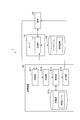
- FIG. 1 schematically shows an example in which the management system 1 is applied.
- the management system 1 includes at least the power transmission device 91 of the non-contact power feeding system 90. Although only one power transmission device 91 is shown in FIG. 1, the management system 1 may include a plurality of power transmission devices 91.
- the management system 1 may further include a server 10.
- the power transmission device 91, the server 10, and the terminal 20 can transmit and receive data to and from each other via the communication network N.
- the configuration of the communication network N is not limited at all, and the communication network N may be constructed by an arbitrary communication network such as the Internet or an intranet.
- the non-contact power supply system 90 includes a power transmission device 91 and a power reception device 92, and supplies power from the power transmission device 91 to the power reception device 92 in a non-contact manner using magnetic coupling between coils such as a magnetic resonance method and an electromagnetic induction method. It is a system to do.
- the power transmission device 91 includes a transmission power conversion device (for example, a rectifier circuit, a DC / DC converter, an inverter circuit, etc.) 91a and a power transmission coil device 91b.
- the power receiving device 92 includes a power receiving coil device 92 a and a received power conversion device (for example, a rectifier circuit or a DC / DC converter) 92 b and is mounted on the moving object V.
- the electric power sent to the power receiving device 92 is stored in the battery 93 of the moving object V.
- Each of the power transmission device 91 and the power reception device 92 includes hardware elements such as a processor, a memory, an input / output interface, and a communication interface.
- the method for transmitting power in a non-contact manner is not limited to the magnetic field resonance method and the electromagnetic induction method, and other methods such as an electromagnetic coupling method and a radio wave method may be used.
- the server 10 is a computer that manages information related to the power transmission device 91.
- the server 10 can be a server of a guidance system such as a car navigation system.
- the management system 1 may include a plurality of servers 10.
- the terminal 20 is a computer that displays information related to the power transmission device 91 to the user, and is also referred to as a user terminal.
- the type of computer used as the terminal 20 is not limited, and the terminal 20 may or may not be mounted on the moving object V.
- the terminal 20 may be a car navigation system, or a mobile terminal such as a high-function mobile phone (smart phone), a mobile phone, a personal digital assistant (PDA), a tablet, or a laptop computer.
- the terminal 20 may or may not be connected to the system in the moving object V.
- the management system 1 may include a plurality of terminals 20.
- the management system 1 specifies the power transmission level of the power transmission device 91 and outputs the result.
- the management system 1 may specify and output the power transmission level according to the charging request from the terminal 20, or may specify and output the power transmission level without acquiring the charging request.
- the power transmission device 91 may receive the charging request directly from the terminal 20 or may receive it via the server 10.
- the power transmission device 91 may directly transmit the processing result (specified power transmission level) to the terminal 20 or may transmit via the server 10.
- the management system 1 may temporarily store the processing result in the database 30 and transmit the processing result read from the database 30 to the terminal 20 or directly transmit the processing result to the terminal 20 without storing the processing result in the database 30. May be.
- the timing for specifying the power transmission level and the mode of data transmission / reception between devices are not limited at all. Below, a typical aspect is illustrated.
- the “power transmission level” is an index indicating the possibility of power transmission by the power transmission device (in other words, the possibility of supplying power from the power transmission device to the power receiving device).
- the power transmission level not only indicates whether or not power transmission is possible, but also indicates how much power can be transmitted when power transmission is possible.
- the power transmission level includes at least three levels of an impossible level, a restriction level, and a normal level, and one power transmission level is specified from the plurality of candidates.
- Impossible level means that power transmission is impossible.
- the restriction level means that power transmission is possible under a predetermined restriction.
- the normal level means that power transmission is possible without the limitation. For example, the normal level indicates that power transmission according to the specification of the power transmission device is possible.
- restriction that distinguishes the restriction level from the normal level is a concept that is determined by the relative relationship between these two types of levels. That is, “no restriction” at the normal level means that there is no restriction applied at the restriction level, and does not mean that transmission can be performed without any restriction. For example, if the power itself provided to the power transmission device 91 is limited, the battery 93 of the moving object V may not be fully charged even at the normal level.
- restrictions on the types of restrictions that exist at the restriction level but do not exist at the normal level include restrictions on electric power (unit: kilowatt (kW)), restrictions on transmission time (unit: hours (h)), restrictions on electric energy (unit: kilowatt hours (kWh)), power efficiency (% ).
- a restriction based on any combination of a plurality of parameters selected from these parameters may be used.
- restrictions based on other parameters different from these parameters may be used.
- the power range P Lmin to P Lmax guaranteed at the limit level is less than P N.
- the value P Lmin is the minimum value of power at the limit level
- the value P Lmax is the maximum value of power at the limit level. If the guaranteed power is less than PLmin , the power transmission level is not possible.
- the power transmission possible time (normally possible time) guaranteed at the normal level is equal to or longer than H Nmin
- the power transmission possible time range H Lmin to H Lmax guaranteed at the limit level is less than H Nmin .
- the value HLmin is the minimum value of the transmittable time at the limit level
- the value HLmax is the maximum value of the transmittable time at the limit level. If the guaranteed power transmission time is less than HLmin , the power transmission level is an unacceptable level.
- the range of power amounts W Lmin to W Lmax guaranteed at the limit level is less than W Nmin .
- the value WLmin is the minimum value of the electric energy at the limit level
- the value WLmax is the maximum value of the electric energy at the limit level. If the guaranteed power amount is less than W Lmin , the power transmission level is not possible.
- the power efficiency (normal efficiency) guaranteed at the normal level is equal to or higher than E Nmin
- the power efficiency range E Lmin to E Lmax guaranteed at the limit level is less than E Nmin .
- the value E Lmin is the minimum value of the power efficiency at the limit level
- the value E Lmax is the maximum value of the power efficiency at the limit level. If the guaranteed power efficiency is less than ELmin , the power transmission level is not possible.
- At least one of the normal level and the restriction level may be further subdivided into a plurality of levels based on an arbitrary parameter. For example, if the minimum power amount guaranteed at the normal level is W Na and W Nb (> W Na ) is further set as the power amount at the normal level, the power amount is not less than W Na but less than W Nb . A certain normal level Na and a normal level Nb whose electric energy is W Nb or more can be set. At this time, the power level at the limit level is naturally limited to less than W Na .
- the transmission time of the ranging H Lmin ⁇ H Lmax guaranteed with a restriction level, a range of less than H Lmin H La Ra, ranges of less than H La or H Lb Rb, and H Lb or H Lmax less
- the limit level La corresponding to the range Ra, the limit level Lb corresponding to the range Rb, and the limit level Lc corresponding to the range Rc are set.
- Charging request is information indicating a request for charging the mobile unit V to the battery 93.
- the specific content of the request for charging is not limited, but may be, for example, the current remaining battery level (SOC: State Of Charge), the required or desired charge amount, and the charge time. May be.
- the charge request may indicate that the SOC should be reduced from 30% to 100%, that the maximum time that can be spent for charging is 1 hour, or that the SOC is reduced from 40% to 80% within 2 hours. You may show that it raises to%.
- the power transmission device 91 includes a receiving unit (for example, a receiver) 911, a detection unit (for example, a detector) 912, a storage unit (for example, a memory) 913, and a specifying unit (for example, a controller) 914 as functional components. , And an output unit (for example, output device) 915.
- a receiving unit for example, a receiver
- a detection unit for example, a detector
- storage unit for example, a memory
- a specifying unit for example, a controller
- an output unit for example, output device 915.
- These functional components are realized by a processor executing a management program installed in the power transmission apparatus 91 to control hardware elements such as a memory and a communication interface.
- the receiving unit 911 is a functional element that receives a charging request from the terminal 20 or the server 10.
- the receiving unit 911 is realized by the processor executing the management program, reading / writing data from / to the memory, and controlling the communication interface.
- the receiving unit 911 outputs the received charging request to the detecting unit 912.
- the detection unit 912 is a functional element that detects the state of the power transmission device 91.
- the detection unit 912 is realized by a processor executing a management program, reading / writing data from / to a memory, and controlling a sensor provided in the power transmission device 91.
- the state of the power transmission device refers to the inside or outside of the power transmission device at a certain point in time. The type of state detected is not limited.
- the detection unit 912 indicates the state of hardware elements such as a circuit (for example, an inverter circuit, a rectifier circuit, a resonance circuit, a communication circuit) in the power transmission device 91 and a device (for example, a foreign object detection device) associated with the power transmission device 91. It may be detected.
- a circuit for example, an inverter circuit, a rectifier circuit, a resonance circuit, a communication circuit
- a device for example, a foreign object detection device associated with the power transmission device 91. It may be detected.
- the detection unit 912 detects whether these hardware elements are normal or abnormal (for example, short circuit, element breakage, sensor inability) The operating status of the wear element can be detected.
- the detection unit 912 may detect the temperature in the power transmission device 91.
- the temperature in the power transmission device may be the temperature of the internal space of the power transmission device 91 or the temperature of a specific part of the power transmission device 91 (element temperature of each circuit, ferrite temperature of the resonance circuit, etc.).
- the detection unit 912 can detect the temperature.
- the detection unit 912 may detect a foreign object existing around the power transmission device 91.
- the “foreign matter” is an object that may reduce power efficiency or hinder power transmission.
- the detection unit 912 may detect a foreign object that is likely to exist between the power transmission device 91 and the power reception device 92.
- the detection unit 912 detects a foreign object by providing a foreign object detection coil formed of a conductive wire as a detection unit 912 in the power transmission device 91 and detecting a disturbance of magnetic flux linked to the coil as a change in induced voltage. Can do. Further, it can be determined that the power efficiency decreases as the change in the induced voltage of the detection unit 912 (hereinafter, also simply referred to as “change in the induced voltage”) increases.
- the timing at which the detection unit 912 operates is not limited.
- the detection unit 912 may detect the state of the power transmission device 91 when a charge request is input from the reception unit 911, or at any timing without receiving an input of a charge request (for example, periodically) ) The state of the power transmission device 91 may be detected.
- the detecting unit 912 generates state information indicating the detected state and outputs the information to the specifying unit 914.
- the detection unit 912 outputs state information to the specifying unit 914 together with the charge request.
- the expression method of the state information may be arbitrarily determined.
- the state information may be represented by a binary value (for example, “0” or “1”), or the measurement value may be used as the state information as it is.
- whether a hardware element is normal or abnormal, whether a foreign object exists, can be expressed by a binary value, and temperature can be expressed by a measured value.
- the storage unit 913 is a functional element that stores the relationship between the state of the power transmission device 91 and the power transmission level, and is realized by a memory.
- the “relation between the state of the power transmission device and the power transmission level” is a rule used for specifying the power transmission level from the state of the power transmission device, and this rule is hereinafter referred to as “specific rule”.
- the storage unit 913 stores data or an algorithm indicating this relationship (specific rule).
- the expression method of the specific rule is not limited.
- the specific rule may be represented by a correspondence table indicating a correspondence relationship between the state of the power transmission device 91 and the power transmission level.
- the specific rule may be represented by a predetermined algorithm for calculating a power transmission level without using a correspondence table. In any case, by using the specific rule, one power transmission level is specified when the state of the power transmission device 91 is given as a condition.
- the power transmission device 91 since the power transmission device 91 has various states and power transmission levels, various relationships can be set between the state and the power transmission level. Therefore, the content of the specific rule is not limited at all. The following are some examples of specific rules.
- storage part 913 may memorize
- the storage unit 913 may store a correspondence table showing the following relationships R a1 to R a3 .
- R a1 Normal level if all circuits in the device are normal.
- R a2 A limit level if all circuits essential for power transmission (for example, inverter circuit, rectifier circuit, resonance circuit) are normal, but a circuit (for example, communication circuit) not directly involved in power transmission is abnormal.
- R a3 Impossible level if any of the circuits essential for power transmission is abnormal.
- a case where there is an abnormality in a communication circuit that is not directly involved in power transmission may be associated with a normal level.
- this state may be associated with the limit level when a circuit essential for power transmission is duplicated and a backup system is operating instead of a normal system.
- the storage unit 913 may store the relationship between the temperature in the power transmission device 91 (hereinafter also simply referred to as “temperature”) and the power transmission level as a specific rule.
- temperature the temperature in the power transmission device 91
- the management system 1 determines that power transmission is impossible. Even if the detected temperature is within the allowable range, if the temperature in the power transmission device 91 is expected to exceed the allowable range after only a relatively short period of power transmission, the management system 1 limits the transmission time to Multiply. In order to make such a determination, the storage unit 913 stores the relationship between the power transmission time and the temperature rise in the power transmission device 91.
- the storage unit 913 may store the relationship between the amount of power supplied from the power transmission device 91 and the temperature rise.
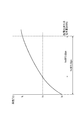
- FIG. 3 is a graph showing an example of such a relationship, in which the vertical axis represents temperature (° C.) and the horizontal axis represents time (h) or electric energy (kWh).
- This graph shows the temperature change when the temperature inside the power transmission device 91 is continued to operate the power transmission device 91 since a standard value t A.
- the value t L is a limit value of the allowable temperature range. When the temperature exceeds the value t L , it is considered that power transmission from the power transmission device 91 is impossible. If the temperature at the start of power transmission is t A , the maximum power transmission time is h A (or the maximum power supply amount is p A ).
- the power transmission possible time is h B shorter than h A (or suppliable power) amount is less p B than p a).
- the power transmission level is specified as the limit level.
- Even temperature is a t B the charging time that is time or request required charging if less h B would power level is specified as the normal level. Such specification is the same for the electric energy.
- the storage unit 913 stores specific rules as shown in the graph of FIG. 3 in the form of data, functions, programs, or the like.
- storage part 913 may memorize
- the storage unit 913 may store a correspondence table indicating the following relationships R b1 to R b3 .
- Rb1 Normal level when no foreign matter is present.
- R b2 Limit level if foreign matter is present but the change in induced voltage is less than threshold Ta.
- R b3 Impossible level when there is foreign matter whose induced voltage change is greater than or equal to the threshold Ta.
- storage part 913 may memorize
- the storage unit 913 may store a correspondence table indicating the following relationships R c1 to R c3 .
- R c1 Normal level when all circuits in the apparatus are normal and there is no foreign object.
- Rc2 All circuits essential for power transmission (for example, inverter circuit, rectifier circuit, resonance circuit) are all normal, but a circuit (for example, communication circuit) that is not directly involved in power transmission is abnormal, or there is a foreign object If the induced voltage change is less than the threshold Ta, the limit level.
- R c3 Impossible level when there is an abnormality in any of the circuits essential for power transmission, or when there is a foreign object whose induced voltage change is greater than or equal to the threshold value Ta.
- the storage unit 913 may store a correspondence table showing the following relationships R d1 to R d4 . It is assumed that the first restriction level is less restrictive regarding power transmission than the second restriction level.
- R d1 Normal level when all circuits in the apparatus are normal and no foreign matter is present.
- R d2 The first limit level if foreign matter is present but the induced voltage change is less than the threshold Ta.
- R d3 The second restriction level if all circuits essential for power transmission (for example, inverter circuit, rectifier circuit, resonance circuit) are normal but a circuit (for example, communication circuit) not directly involved in power transmission is abnormal.
- R d4 Impossible level when there is an abnormality in any of the circuits indispensable for power transmission, or when there is a foreign object whose induced voltage change is greater than or equal to the threshold value Ta.
- the storage unit 913 may further store device information indicating the power transmission performance of the power transmission device 91.
- This device information can be used as an additional or auxiliary parameter for identifying the power transmission level using a specific rule.
- the power transmission performance includes output voltage, output current, charging time, and the like, but the parameters indicating the power transmission performance are not limited to these. For example, when specifying the power transmission parameter from the temperature in the power transmission device 91, the output voltage and the output current can be used when obtaining the required power amount from the charging time indicated by the charge request.
- the identification unit 914 is a functional element that identifies the power transmission level of the power transmission device 91 corresponding to the state detected by the detection unit 912. “Identify” is a process of deriving one power transmission level, and its specific method is not limited. For example, the process of specifying one power transmission level using the correspondence table and the process of obtaining the power transmission level using some algorithm are included in the concept of “identifying”.
- the identifying unit 914 outputs the identified power transmission level to the output unit 915.
- the specifying unit 914 is realized by a processor executing a management program to read / write data from / to a memory.
- the specifying unit 914 refers to the specific rule stored in the storage unit 913 and specifies the power transmission level corresponding to the state information. For example, assuming that the storage unit 913 stores the above relationships R a1 to R a3 and state information indicating an abnormality of the communication circuit is input, the specifying unit 914 has the power transmission level of the power transmission device 91 at the limit level. Is identified. In another example, it is assumed that the storage unit 913 stores the relationship between the temperature and the power transmission time or the amount of supplied power shown in FIG. 3 as a specific rule.
- the specifying unit 914 applies a default value (for example, a time or power amount required to change the SOC from 0% to 100%) predetermined for the transmission time or the supplied power amount to the specifying rule.
- the power transmission level may be specified. For example, if the temperature indicated by the state information is t X ( ⁇ t L ) and the default value of the power transmission time or the amount of supplied power is applied to the specific rule illustrated in FIG. 3, the specifying unit 914 may exceed the temperature t L. For example, the power transmission level is specified as the restriction level. If the temperature indicated by the status information t L or more, the specifying unit 914 specifies the power transmission level is impossible level.
- the specifying unit 914 specifies that the power transmission level of the power transmission device 91 is an unacceptable level.
- the specifying unit 914 may further specify the power transmission level based on the charge request. However, when the power transmission level is specified as the impossible level based only on the state information, the specifying unit 914 sets the “impossible level” as the final processing result without considering the charge request.
- the storage unit 913 stores the specific rule shown in FIG. 3 and device information. Further, it is assumed that state information indicating the temperature in the power transmission device 91 and a charge request indicating that “the SOC is changed from the current 30% to 100%” are input. In this case, the specifying unit 914 calculates a time (required time for charging) necessary to satisfy the charging request based on the charging request and the device information. Subsequently, the specifying unit 914 determines whether the temperature in the power transmission device 91 exceeds the allowable range during the requested charging based on the required time, the current temperature in the device indicated by the status information, and the specific rule. determining whether a (whether or not the temperature exceeds t L).
- the specifying unit 914 specifies that the power transmission level is a normal level. If the temperature exceeds the allowable range, the specifying unit 914 indicates that the power transmission level is a limit level. Is identified. If the temperature indicated by the state information is outside the allowable range, the specifying unit 914 specifies that the power transmission level is an unacceptable level without considering the charge request.
- the output unit 915 is a functional element that outputs the power transmission level specified by the specifying unit 914.
- the output unit 915 is realized by the processor executing the management program, reading / writing data from / to the memory, and controlling the communication interface.
- the output unit 915 outputs a processing result including the identified power transmission level and power transmission device ID.
- the processing result may indicate the reason (for example, “hardware abnormality”, “temperature”, etc.) specified as the restriction level or the impossibility level.
- the power transmission device ID is an identifier for identifying each power transmission device, and is stored in advance in the memory of the power transmission device 91.
- the output unit 915 may transmit the processing result to the server 10, may transmit it to the terminal 20, or may output it to a computer system (not shown) other than the management system 1. . As long as a user such as a user of the moving body V or an operator of the management system 1 can finally know the power transmission level of the power transmission device 91, the output destination of the processing result is not limited.
- the server 10 includes a management unit (for example, a controller) 11 as a functional component.
- a management unit for example, a controller
- FIG. 4 shows a general hardware configuration of the server 10.
- the server 10 includes a processor 101 that executes an operating system, application programs, and the like, a main storage unit 102 that includes a ROM and a RAM, an auxiliary storage unit 103 that includes a hard disk, a flash memory, and the like, and a network card or wireless
- the communication control unit 104 includes a communication module, an input device 105 such as a keyboard and a mouse, and an output device 106 such as a display.
- Each functional element of the server 10 reads predetermined software on the processor 101 or the main storage unit 102, operates the communication control unit 104, the input device 105, the output device 106, and the like under the control of the processor 101. This is realized by reading and writing data in the storage unit 102 or the auxiliary storage unit 103. Data or a database necessary for processing is stored in the main storage unit 102 or the auxiliary storage unit 103.
- the management unit 11 is a functional element that manages the specified power transmission level for one or more power transmission devices 91. More specifically, the management unit 11 stores the specified power transmission level in the database 30 or transmits it to the terminal 20.
- the management unit 11 is realized by the processor 101 executing a management program installed in the server 10 to read / write data from / to the main storage unit 102 or the auxiliary storage unit 103 and control the communication control unit 104. .
- the management unit 11 stores a record indicating the processing result (power transmission device ID and power transmission level) received from the power transmission device 91 in the database 30.
- One record indicating the processing result of one power transmission device 91 may include other attributes related to the power transmission device 91.
- the management unit 11 can receive processing results from the plurality of power transmission apparatuses 91, and thus the database 30 can store a plurality of records for the plurality of power transmission apparatuses 91.
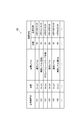
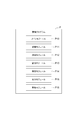
- FIG. 5 is an example of a record stored in the database 30.
- the reasons for the restriction level and the impossible level (“temperature”, “hardware abnormality”, “foreign matter”) are registered as part of the processing result, but the reason registration may be omitted.
- the power transmission apparatus 91 with IDs “101”, “104”, and “105” can be used without any particular limitation, and the power transmission apparatus 91 with IDs “102” and “106” has limitations when transmitting power. It can be seen that the power transmission device 91 whose ID is “103” cannot be used.
- each record includes a geographical position where the power transmission apparatus 91 is installed (hereinafter simply referred to as “position”) and an operation history of the power transmission apparatus 91 in addition to the power transmission apparatus ID and the power transmission level.
- position the position of the power transmission device 91 is indicated by two-dimensional coordinates (x, y) represented by latitude and longitude.
- the method of expressing the position is not limited, and another position such as a location may be used.
- the position may be indicated by a value.
- the operation history is a record of past power transmission of the power transmission device 91.
- the operation history is shown as a combination of the number of operations and the last operation date and time, but the method of expressing the operation history is not limited.
- the operation history may be a set of past operation dates, may be indicated by either the number of operations or the last operation date, or may be an average value of the number of operations per unit time (for example, per day) May be shown.
- This operation history is registered or updated every time power transmission is performed in the power transmission device 91.
- the operation history registration / update method is not limited.
- the server 10 may execute the process, or another information processing apparatus may execute the process.
- the mounting method of the database 30 is not limited.
- the database 30 may be a relational database or a CSV file.
- the configuration of each record is not limited to the example of FIG. 5, and other items may be included in the record, some of the items shown in FIG. 5 may be omitted if necessary, Normalization or redundancy may be performed.
- the data shown in FIG. 5 may be divided into a table indicating the power transmission level of each power transmission device 91 and a table indicating the position and movement history of each power transmission device 91.
- the management unit 11 can notify the user of the power transmission level of the power transmission device 91 by transmitting the processing result to the terminal 20.
- the management unit 11 may transmit the processing result to the terminal 20 when the request from the terminal 20 is received, and the processing result may be transmitted at an arbitrary timing (for example, periodically) without requiring the reception.
- Push distribution may be performed toward one or more terminals 20.
- the management unit 11 transmits the charging request to at least one power transmission device 91, and receives the processing result transmitted from each power transmission device 91 in response to the transmission. Then, the management unit 11 transmits the received one or more processing results to the terminal 20 as a response to the charge request.
- the terminal 20 displays the processing result. If the management part 11 transmits the process result which also shows the position of the power transmission apparatus 91 to the terminal 20, the terminal 20 can display the power transmission level and location of each power transmission apparatus 91. It can be determined whether the power transmission device 91 should be used. In order to obtain only information related to the power transmission device 91 in a specific area, the charging request may include the current position of the user or the moving object V and the search range (for example, within a radius of 5 km).
- the management unit 11 When the charging request is not received from the terminal 20, the management unit 11 reads out the processing result of each power transmission device 91 from the database 30 and transmits the information to the terminal 20. Or the management part 11 receives the request
- the management unit 11 prioritizes the information on the power transmission device 91 identified as the normal level over the information on the power transmission device 91 identified as the restriction level. You may transmit to the terminal 20.
- “transmitting (outputting) certain information (first information) with priority over other information (second information)” means that the user can make the first information easier than the second information. Output at least the first information so that it can be recognized.
- the method for realizing this is not limited.
- the management unit 11 may output only the first information without outputting the second information, or the first information is more than the second information. Both information may be output after setting the display order to be displayed first.
- the management unit 11 may transmit only the processing result of the power transmission device 91 whose power transmission level is the normal level. In this case, only the information on the power transmission device that can charge the battery of the mobile body without particular limitation is transmitted. The user can be guided.
- the management unit 11 may transmit only the processing result indicating either the normal level or the restriction level, and in this case, more power transmission devices that can be charged can be guided to the user.
- one power transmission device 91 may be determined to be a normal level for a certain user, and may be determined to be a restriction level for another user. That is, the power transmission device 91 that does not completely satisfy the charging request of some users may completely satisfy the charging request of other users.
- the charging request of some users is completely satisfied.
- Other users can be guided to the non-power transmission device 91. As a result, it is possible to equalize the operation rate among the plurality of power transmission devices 91 and increase the overall operation rate of the power transmission device 91 in the management system 1.
- the management unit 11 may execute the following process when there are two or more power transmission apparatuses 91 having the same power transmission level. That is, the management unit 11 first compares the operation frequencies obtained from the operation history in the database 30 between the power transmission apparatuses 91. Then, the management unit 11 transmits (outputs) the information of the power transmission device 91 on the side with the lower operation frequency among the two or more power transmission devices in preference to the information of the remaining power transmission devices 91.
- the definition of “priority” here is the same as the above (“output at least the first information so that the user can easily recognize the first information rather than the second information”).
- the “power transmission device having a lower operation frequency” is a power transmission device having an operation frequency lower than the operation frequency of at least one power transmission device among the two or more power transmission devices.
- standard which divides two or more power transmission apparatuses into two groups is not limited.
- the management unit 11 may set a power transmission device other than the power transmission device with the highest operation frequency as the “power transmission device with the lower operation frequency”.
- the management unit 11 may set only the power transmission device with the lowest operation frequency as the “power transmission device with the lower operation frequency”.
- the management unit 11 arranges two or more power transmission devices in ascending or descending order of operation frequency, and sets about half of the power transmission devices on the low operation frequency side as “power transmission devices on the low operation frequency side”. May be.
- the method for obtaining the operating frequency is not limited.
- the management unit 11 may regard the number of operations as the operation frequency as it is, or may determine that the operation frequency is lower as the elapsed time from the last operation date is longer.
- the database 30 stores the processing results shown in FIG. 5, there are three normal-level power transmission apparatuses with IDs “101”, “104”, and “105”. If the operation frequency is regarded as the operation frequency as it is, the IDs of the three power transmission devices are arranged in ascending order of the operation frequency, and “105”, “101”, and “104” are obtained. Therefore, the management unit 11 may determine only the power transmission device with the ID “105” as “the power transmission device with the lower operation frequency” or only the two power transmission devices with the IDs “105” and “101”.
- the management unit 11 may determine only the power transmission device with the ID “104” as “the power transmission device with the lower operation frequency” or only the two power transmission devices with the IDs “104” and “101”. You may determine as "the power transmission apparatus with the low operation frequency.”
- the user By transmitting information on the power transmission device 91 having a relatively low operating frequency to the terminal 20, the user is encouraged to use the power transmission device 91, thereby avoiding a situation where only a specific power transmission device 91 is used.
- the operating rates of the plurality of power transmission devices 91 can be leveled. This can lead to an increase in the overall operating rate of the power transmission device 91 in the management system 1.
- the function and configuration of the management system 1A according to the second embodiment will be described with reference to FIGS.
- the second embodiment is different from the first embodiment in that the server specifies the power transmission level of the power transmission device.
- the server specifies the power transmission level of the power transmission device.
- the management system 1A includes at least a power transmission device 91A and a server 10A, and provides information related to the power transmission device 91A to the terminal 20.
- the power transmission device 91A includes a detection unit (for example, a detector) 912A as a functional component.
- the detection unit 912A is realized by a processor executing a management program, reading / writing data from / to a memory, and controlling a sensor and a communication module provided in the power transmission apparatus 91A.
- the detection unit 912A detects an arbitrary type of state related to the power transmission device 91A.
- the timing at which the detection unit 912A operates is not limited.
- the detection unit 912A may detect the state of the power transmission apparatus 91A when receiving a detection request from the server 10A.
- the detection unit 912A may detect the state of the power transmission device 91A at an arbitrary timing (for example, periodically) without receiving an input of a detection request.
- the detection unit 912A generates state information indicating the detected state and transmits the information to the server 10A.
- the state information in the present embodiment further includes the ID of the power transmission device 91A (power transmission device ID) so that the server 10A can identify the transmission source of the state information.
- the server 10A includes a receiving unit (for example, a receiver) 12, a specifying unit (for example, a controller) 13, and an output unit (for example, an output device) 14 as functional components, and can access the database 30A.
- the database 30A is a device that stores a specification rule 31 used to specify the power transmission level of the power transmission device 91A and a processing result 32 indicating the specified power transmission level.
- the receiving unit 12 is a functional element that receives a charging request from the terminal 20 and outputs the request to the specifying unit 13.
- the contents and configuration of the charge request are the same as in the first embodiment.
- the specifying unit 13 is a functional element that specifies the power transmission level of the power transmission device 91A corresponding to the state detected by the detection unit 912A of the power transmission device 91A.
- the specifying unit 13 is realized by the processor 101 executing the management program installed in the server 10A, reading / writing data from / to the main storage unit 102 or the auxiliary storage unit 103, and controlling the communication control unit 104. .
- the specifying unit 13 specifies the power transmission level using the specifying rule 31. While the specifying unit 13 can specify the power transmission levels of the plurality of power transmission devices 91A, the specification rule is not necessarily the same among all the power transmission devices 91A. Therefore, the specific rule 31 in the present embodiment includes the power transmission device ID as a data item, which makes it possible to distinguish the specific rule of each power transmission device 91A.
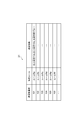
- An example of the specific rule 31 in the present embodiment is shown in FIG. Since the specifying unit 13 may execute the specifying process using the power transmission performance of the power transmission device 91A as in the first embodiment, each record of the specification rule 31 further includes the power transmission performance as a data item as shown in FIG. May be included.
- FIG. 7 specific values of specific rules are schematically shown as “Rule Ra” or the like, but specific contents and configurations of individual specific rules are the same as those in the first embodiment. Further, the specific contents and configuration of the power transmission performance are not limited to the example of FIG.
- the specifying unit 13 receives the state information from the power transmission device 91A, refers to the specific rule 31, and corresponds to the state information (the power transmission device ID and the detected state). Identify the power transmission level.
- the identification part 13 may transmit the detection request
- the specifying unit 13 transmits a detection request to one or more power transmission devices 91A according to the charging request, and is transmitted from each power transmission device 91A according to the transmission. Receive status information.
- specification part 13 specifies the power transmission level corresponding to the state information (power transmission apparatus ID and the detected state) with reference to the specific rule 31.
- the specifying unit 13 outputs the specified power transmission level to the output unit 14 together with the power transmission device ID.
- the output unit 14 is a functional element that outputs a processing result including the input power transmission level and power transmission device ID.
- the output unit 14 is realized when the processor 101 executes a management program, reads / writes data from / to the main storage unit 102 or the auxiliary storage unit 103, and controls the communication control unit 104.
- the output unit 14 may transmit the processing result to the terminal 20 without storing the processing result in the database 30A regardless of whether or not the charging request is received.
- the output unit 14 may store the processing result in the database 30A, or may output the result to a computer system (not shown) other than the management system 1A.
- the output destination of the processing result is not limited as long as a user such as a user of the moving body V or an operator of the management system 1A can finally know the power transmission level of the power transmission device 91A. .
- the output unit 14 may read the processing result 32 from the database 30 ⁇ / b> A in response to the charging request received from the terminal 20 and transmit the data to the terminal 20.
- the output unit 14 receives a request including the current position and search range of the user or the moving object V from the terminal 20 in order to obtain only information related to the power transmission device 91A in a specific area, and within the area that matches the request. Only the processing result 32 of the power transmission device 91A may be transmitted to the terminal 20 as a response.
- the data structure of the processing result 32 can be set in the same manner as in the first embodiment (FIG. 5).
- the output unit 14 gives priority to the information of the power transmission device 91A identified as the normal level over the information of the power transmission device 91A identified as the restriction level. You may transmit to the terminal 20. Alternatively, the output unit 14 may transmit only the processing result indicating either the normal level or the limit level. Alternatively, when there are two or more power transmission devices 91A having the same power transmission level, the output unit 14 compares the operation frequencies obtained from the operation history in the database 30A (processing result 32) between the power transmission devices 91A. Then, among the two or more power transmission devices, the information on the power transmission device 91A having the lower operation frequency may be transmitted (output) with priority over the information on the remaining power transmission devices 91A. As described above, the output priority may be set in the same manner as in the first embodiment, and the setting method is various as in the first embodiment.
- FIG. 8 is a flowchart illustrating a management method according to the present disclosure, which is executed by the management systems 1 and 1A.
- the processing shown in this flowchart is started when the management system 1 or 1A acquires a charge request from the terminal 20 or when a predetermined execution time has arrived without receiving the charge request.
- the status information is obtained by detecting the status of the power transmission devices 91 and 91A (step S11, detection step). Then, the power transmission level of the power transmission apparatuses 91 and 91A is specified by referring to the specific rule using the state information (step S12, specific step). Then, the identified power transmission level is output (step S13, output step).
- the management systems 1 and 1A set the power transmission levels of the power transmission devices 91 and 91A before the power transmission of the power transmission devices 91 and 91A is started (in other words, before the power supply to the power receiving device 92 of the moving object V is started). Output.
- step S13 is performed before the said power transmission is started, and the process of step S11, S12 used as the premise of the process is also performed before the start of the said power transmission.
- the apparatus for executing the processing of each step is not limited.
- the management program P includes a main module P10, a reception module P11, a detection module P12, a storage module P13, a specific module P14, an output module P15, and a management module P16.
- the main module P10 is a part that comprehensively controls the management of the power transmission level of the power transmission device.
- the functions realized by executing the reception module P11, the detection module P12, the storage module P13, the specific module P14, the output module P15, and the management module P16 are respectively the reception unit, detection unit, and storage unit ( Alternatively, the functions of the database), the specifying unit, the output unit, and the management unit are the same. If the functional components are divided among a plurality of computers as in the above embodiments, the necessary modules are provided for each computer. In the management program P corresponding to the second embodiment, the management module P16 may be omitted.
- the management program P may be provided after being fixedly recorded on a tangible recording medium such as a CD-ROM, DVD-ROM, or semiconductor memory. Alternatively, the management program P may be provided via a communication network as a data signal superimposed on a carrier wave.
- the management system is a management system for a power transmission device that can transmit power to a mobile power receiving device in a contactless manner, and a detection unit that detects the state of the power transmission device;
- a storage unit that stores the relationship between the state of the power transmission device and the power transmission level indicating the power transmission possibility of the power transmission device, and a specifying unit that identifies the power transmission level corresponding to the state detected by the detection unit with reference to the storage unit
- an output unit that outputs the power transmission level specified by the specifying unit before the power transmission device starts power transmission, and the power transmission level is set to an unacceptable level indicating that power transmission is impossible, and under a predetermined limit. At least a limit level indicating that power can be transmitted and a normal level indicating that power can be transmitted without limitation.
- a management method is a management method executed by a management system for a power transmission device capable of contactless power transmission to a power receiving device of a mobile body, the detection step detecting the state of the power transmission device; A specific step of identifying a power transmission level corresponding to the state detected in the detection step with reference to a storage unit that stores a relationship between a state of the power transmission device and a power transmission level indicating the possibility of power transmission of the power transmission device; Output step of outputting the power transmission level specified in the specific step before the power transmission starts, and the power transmission level can be transmitted under a predetermined limit and a non-transmission level indicating that power transmission is impossible. It includes at least a restriction level indicating that it is present and a normal level indicating that transmission is possible without restriction.
- a management program is a management program for causing a computer system including one or more computers to function as a management system for a power transmission device capable of transmitting power to a mobile power receiving device in a contactless manner.
- a detection unit that detects the state of the power transmission, a storage unit that stores the relationship between the state of the power transmission device and the power transmission level indicating the possibility of power transmission of the power transmission device, and the state detected by the detection unit with reference to the storage unit
- the computer system functions as an identifying unit that identifies the corresponding power transmission level and an output unit that outputs the power transmission level identified by the identifying unit before the power transmission device starts power transmission.
- the mode of power transmission is an unacceptable level (impossible to transmit power), a restriction level (possible power transmission with restriction), or a normal level (no restriction) Output in at least three stages.
- a restriction level possible power transmission with restriction
- a normal level no restriction
- the specifying unit specifies the power transmission level based on both the charging request obtained from the predetermined device and indicating the request for charging the moving body and the detected state. Good.
- the request for charging the mobile body it is possible to specify the power transmission level according to the status of each mobile body that is the target of power transmission.
- the power transmission device may include a detection unit, a specification unit, and an output unit.
- the power transmission device can specify and output the power transmission level of its own device without using an intermediary device such as a server.
- each of the plurality of power transmission devices includes a detection unit, a server that can communicate with the plurality of power transmission devices includes a specifying unit and an output unit, and thereby the server is configured for each of the plurality of power transmission devices.
- the power transmission level may be specified.
- the output unit may output the information on the power transmission device identified as being at the normal level in preference to the information on the power transmission device identified as being at the restriction level.
- the power transmission level is specified further considering the charging request, the power transmission device specified as the restriction level for the first user (mobile body) is specified as the normal level for the second user (mobile body).
- the information on the power transmission device is preferentially provided to the second user (moving body).
- a power transmission device that does not completely satisfy the charging request of some users (mobile units) may completely satisfy the charging request of other users (mobile units).
- the operating rate can be leveled among the plurality of power transmission devices. Eventually, it can be expected to increase the overall operating rate of the power transmission device in the management system.
- the management system further includes a database that stores operation histories of a plurality of power transmission apparatuses, and when the output unit includes two or more power transmission apparatuses having the same power transmission level, the two or more power transmission apparatuses
- the operation frequency obtained from the operation history stored in the database is compared between the devices, and the information on the power transmission device on the side having the lower operation frequency is selected from the two or more power transmission devices. You may give priority and output rather than the information of the remaining power transmission apparatuses.
- the output unit transmits the identified power transmission level of the power transmission device together with the position of the power transmission device to the terminal of the user of the mobile body, whereby the terminal determines the power transmission level and position of the power transmission device. It may be displayed.
- the terminal determines the power transmission level and position of the power transmission device.
- the present disclosure has been described in detail based on the embodiment. However, the present disclosure is not limited to the above embodiment. The present disclosure can be variously modified without departing from the gist thereof.
- the management system also has a function of transmitting information related to the power transmission device to the user terminal, but this transmission function is not essential. Therefore, the function of guiding a specific power transmission device to the user is not essential.
- the management system provides the processing result to the user terminal, but the management system provides the processing result to a device other than the user terminal (for example, a power receiving device or an information processing device outside the management system). May be.
- the management system includes a database, but the database arrangement mode is not limited to this.
- this database may be in another information processing system different from the management system, or the database may be constructed in the server.
- the devices in the management system can access the database via the communication network, the location of the database is not limited.
- the database is not an essential component.
Landscapes
- Engineering & Computer Science (AREA)
- Power Engineering (AREA)
- Transportation (AREA)
- Mechanical Engineering (AREA)
- Computer Networks & Wireless Communication (AREA)
- Life Sciences & Earth Sciences (AREA)
- Sustainable Development (AREA)
- Sustainable Energy (AREA)
- Charge And Discharge Circuits For Batteries Or The Like (AREA)
- Electric Propulsion And Braking For Vehicles (AREA)
Abstract
Selon un mode de réalisation, l'invention concerne un système de gestion qui gère un dispositif de transmission de puissance pouvant transmettre une puissance sans contact à un dispositif de réception de puissance d'un corps mobile. Un système de gestion comporte une unité de détection pour la détection d'un état du dispositif de transmission de puissance, une unité de mémoire pour la conservation de la relation entre l'état du dispositif de transmission de puissance et le niveau de transmission de puissance indiquant la possibilité de transmission de puissance par le dispositif de transmission de puissance, une unité de spécification pour la spécification du niveau de transmission de puissance correspondant à l'état détecté par l'unité de détection, et une unité de sortie pour l'émission du niveau de transmission de puissance spécifié avant que le dispositif de transmission de puissance ne commence à transmettre la puissance. Le niveau de transmission de puissance inclut au moins un niveau impossible indiquant que la transmission de puissance n'est pas possible, un niveau de restriction indiquant que la transmission de puissance est possible avec une restriction préétablie, et un niveau normal indiquant que la transmission de puissance est possible sans restriction.
Priority Applications (2)
| Application Number | Priority Date | Filing Date | Title |
|---|---|---|---|
| EP16799840.0A EP3306782B1 (fr) | 2015-05-25 | 2016-05-13 | Système, procédé, et programme de gestion d'un dispositif de transmission de puissance |
| US15/697,980 US10454319B2 (en) | 2015-05-25 | 2017-09-07 | System, method, and program for managing power transmission device |
Applications Claiming Priority (2)
| Application Number | Priority Date | Filing Date | Title |
|---|---|---|---|
| JP2015-105345 | 2015-05-25 | ||
| JP2015105345A JP6447359B2 (ja) | 2015-05-25 | 2015-05-25 | 送電装置を管理するためのシステム、方法、およびプログラム |
Related Child Applications (1)
| Application Number | Title | Priority Date | Filing Date |
|---|---|---|---|
| US15/697,980 Continuation US10454319B2 (en) | 2015-05-25 | 2017-09-07 | System, method, and program for managing power transmission device |
Publications (1)
| Publication Number | Publication Date |
|---|---|
| WO2016190132A1 true WO2016190132A1 (fr) | 2016-12-01 |
Family
ID=57394110
Family Applications (1)
| Application Number | Title | Priority Date | Filing Date |
|---|---|---|---|
| PCT/JP2016/064309 WO2016190132A1 (fr) | 2015-05-25 | 2016-05-13 | Système, procédé, et programme de gestion d'un dispositif de transmission de puissance |
Country Status (4)
| Country | Link |
|---|---|
| US (1) | US10454319B2 (fr) |
| EP (1) | EP3306782B1 (fr) |
| JP (1) | JP6447359B2 (fr) |
| WO (1) | WO2016190132A1 (fr) |
Families Citing this family (6)
| Publication number | Priority date | Publication date | Assignee | Title |
|---|---|---|---|---|
| JP6910902B2 (ja) * | 2017-09-15 | 2021-07-28 | 株式会社ダイヘン | 移動装置及び給電システム |
| EP3509186A1 (fr) * | 2018-01-03 | 2019-07-10 | Koninklijke Philips N.V. | Commande de puissance dans un système de transfert de puissance sans fil |
| KR102220909B1 (ko) * | 2018-06-04 | 2021-02-25 | 엘지전자 주식회사 | 무선 전력 시스템 |
| JP6906488B2 (ja) * | 2018-09-05 | 2021-07-21 | 株式会社東芝 | 電子装置及び方法 |
| US11247578B2 (en) * | 2018-11-14 | 2022-02-15 | Ford Global Technologies, Llc | Electric charging stations with docking management and methods of use |
| JP7307615B2 (ja) * | 2019-07-10 | 2023-07-12 | 株式会社Subaru | 電動車両 |
Citations (4)
| Publication number | Priority date | Publication date | Assignee | Title |
|---|---|---|---|---|
| JP2013146133A (ja) * | 2012-01-13 | 2013-07-25 | Pfu Ltd | 電動車両用充電装置、その管理装置、管理方法及び管理システム |
| WO2014157091A1 (fr) * | 2013-03-29 | 2014-10-02 | 日産自動車株式会社 | Système d'alimentation d'électricité sans contact et dispositif d'alimentation d'électricité |
| JP2015008620A (ja) * | 2013-06-26 | 2015-01-15 | キヤノン株式会社 | 無線電力伝送装置、無線電力伝送装置の制御方法、プログラム |
| WO2015068476A1 (fr) * | 2013-11-06 | 2015-05-14 | 本田技研工業株式会社 | Système de transmission d'énergie sans contact |
Family Cites Families (11)
| Publication number | Priority date | Publication date | Assignee | Title |
|---|---|---|---|---|
| JP2010011650A (ja) | 2008-06-27 | 2010-01-14 | Seiko Epson Corp | 送電制御装置、送電装置、電子機器、及び送電制御方法 |
| US8347120B2 (en) * | 2008-08-12 | 2013-01-01 | Ixys Corporation | System and method for conserving power applied to an electrical apparatus |
| JP5050135B2 (ja) | 2010-03-31 | 2012-10-17 | パイオニア株式会社 | 検索装置、ナビゲーション装置、情報提供装置、検索方法、検索プログラムおよび記録媒体 |
| JP5599259B2 (ja) | 2010-08-09 | 2014-10-01 | マスプロ電工株式会社 | 車両の非接触給電システム |
| JP5508637B2 (ja) | 2010-09-02 | 2014-06-04 | 株式会社日本自動車部品総合研究所 | 非接触電力転送装置の異常検出装置、およびそれを備える非接触送電装置、非接触受電装置および車両 |
| US8810198B2 (en) | 2011-09-02 | 2014-08-19 | Tesla Motors, Inc. | Multiport vehicle DC charging system with variable power distribution according to power distribution rules |
| KR101338732B1 (ko) * | 2011-11-10 | 2013-12-06 | 엘지이노텍 주식회사 | 무선전력 송신장치, 무선전력 수신장치, 무선전력 전송 방법, 무선전력 수신 방법, 정보 전송 방법 및 정보 수신 방법 |
| JP5754359B2 (ja) | 2011-11-24 | 2015-07-29 | 株式会社豊田自動織機 | 非接触給電装置及び非接触給電システム |
| JP2013192281A (ja) * | 2012-03-12 | 2013-09-26 | Toyota Industries Corp | 非接触充電システム、非接触充電スタンド、および非接触充電方法 |
| JP2015100173A (ja) | 2013-11-18 | 2015-05-28 | トヨタ自動車株式会社 | 非接触充電システム及び非接触充電システムのペアリング方法 |
| KR101804410B1 (ko) * | 2015-12-17 | 2017-12-04 | 엘지이노텍 주식회사 | 무선 전력 송신기를 위한 송신 코일 모듈 |
-
2015
- 2015-05-25 JP JP2015105345A patent/JP6447359B2/ja active Active
-
2016
- 2016-05-13 EP EP16799840.0A patent/EP3306782B1/fr active Active
- 2016-05-13 WO PCT/JP2016/064309 patent/WO2016190132A1/fr active Application Filing
-
2017
- 2017-09-07 US US15/697,980 patent/US10454319B2/en active Active
Patent Citations (4)
| Publication number | Priority date | Publication date | Assignee | Title |
|---|---|---|---|---|
| JP2013146133A (ja) * | 2012-01-13 | 2013-07-25 | Pfu Ltd | 電動車両用充電装置、その管理装置、管理方法及び管理システム |
| WO2014157091A1 (fr) * | 2013-03-29 | 2014-10-02 | 日産自動車株式会社 | Système d'alimentation d'électricité sans contact et dispositif d'alimentation d'électricité |
| JP2015008620A (ja) * | 2013-06-26 | 2015-01-15 | キヤノン株式会社 | 無線電力伝送装置、無線電力伝送装置の制御方法、プログラム |
| WO2015068476A1 (fr) * | 2013-11-06 | 2015-05-14 | 本田技研工業株式会社 | Système de transmission d'énergie sans contact |
Non-Patent Citations (1)
| Title |
|---|
| See also references of EP3306782A4 * |
Also Published As
| Publication number | Publication date |
|---|---|
| EP3306782A4 (fr) | 2019-05-15 |
| EP3306782A1 (fr) | 2018-04-11 |
| US20170373544A1 (en) | 2017-12-28 |
| JP6447359B2 (ja) | 2019-01-09 |
| EP3306782B1 (fr) | 2022-08-03 |
| US10454319B2 (en) | 2019-10-22 |
| JP2016220464A (ja) | 2016-12-22 |
Similar Documents
| Publication | Publication Date | Title |
|---|---|---|
| JP6447359B2 (ja) | 送電装置を管理するためのシステム、方法、およびプログラム | |
| US10239414B2 (en) | Information providing system, power receiving device, information providing method and information providing program | |
| US11408941B2 (en) | Information processing apparatus, computer-readable storage medium, and information processing method | |
| US11893517B2 (en) | Information processing apparatus, computer-readable storage medium, and information processing method | |
| US11254235B2 (en) | Information processing apparatus, computer-readable storage medium, and information processing method | |
| US9496736B1 (en) | Portable device charging system | |
| EP3369605B1 (fr) | Procédé de présentation de chargeabilité et système de présentation de chargeabilité | |
| US9442548B1 (en) | Device charging system | |
| US20190130318A1 (en) | Charge management server and method of controlling the same | |
| CN110579218B (zh) | 一种规划更换电池路径的方法及终端 | |
| JP6315632B2 (ja) | 情報提供システム、情報機器、および情報提供方法 | |
| WO2020148848A1 (fr) | Dispositif de gestion de transmission/réception de courant, et programme | |
| WO2020213608A1 (fr) | Procédé de commande, système de commande, et programme | |
| CN110634192B (zh) | 停车场出借装置、停车场出借系统及停车场出借方法 | |
| JP7065212B2 (ja) | 送受電管理装置及びプログラム | |
| WO2021100748A1 (fr) | Dispositif de traitement d'informations, programme et procédé de traitement d'informations | |
| US20220363148A1 (en) | Abnormality determination apparatus and information providing apparatus | |
| US20220134894A1 (en) | Control device, non-contact power supply program, and non-contact power supply system | |
| WO2020213609A1 (fr) | Procédé de commande, système de commande et programme |
Legal Events
| Date | Code | Title | Description |
|---|---|---|---|
| 121 | Ep: the epo has been informed by wipo that ep was designated in this application |
Ref document number: 16799840 Country of ref document: EP Kind code of ref document: A1 |
|
| NENP | Non-entry into the national phase |
Ref country code: DE |
|
| WWE | Wipo information: entry into national phase |
Ref document number: 2016799840 Country of ref document: EP |