WO2016189994A1 - 翼、フラップおよび航空機 - Google Patents
翼、フラップおよび航空機 Download PDFInfo
- Publication number
- WO2016189994A1 WO2016189994A1 PCT/JP2016/061970 JP2016061970W WO2016189994A1 WO 2016189994 A1 WO2016189994 A1 WO 2016189994A1 JP 2016061970 W JP2016061970 W JP 2016061970W WO 2016189994 A1 WO2016189994 A1 WO 2016189994A1
- Authority
- WO
- WIPO (PCT)
- Prior art keywords
- flap
- vortex
- wing
- tip
- blade tip
- Prior art date
Links
Images


Classifications
-
- B—PERFORMING OPERATIONS; TRANSPORTING
- B64—AIRCRAFT; AVIATION; COSMONAUTICS
- B64C—AEROPLANES; HELICOPTERS
- B64C3/00—Wings
- B64C3/10—Shape of wings
-
- B—PERFORMING OPERATIONS; TRANSPORTING
- B64—AIRCRAFT; AVIATION; COSMONAUTICS
- B64C—AEROPLANES; HELICOPTERS
- B64C9/00—Adjustable control surfaces or members, e.g. rudders
- B64C9/14—Adjustable control surfaces or members, e.g. rudders forming slots
- B64C9/16—Adjustable control surfaces or members, e.g. rudders forming slots at the rear of the wing
- B64C9/20—Adjustable control surfaces or members, e.g. rudders forming slots at the rear of the wing by multiple flaps
-
- B—PERFORMING OPERATIONS; TRANSPORTING
- B64—AIRCRAFT; AVIATION; COSMONAUTICS
- B64C—AEROPLANES; HELICOPTERS
- B64C23/00—Influencing air flow over aircraft surfaces, not otherwise provided for
- B64C23/06—Influencing air flow over aircraft surfaces, not otherwise provided for by generating vortices
-
- B—PERFORMING OPERATIONS; TRANSPORTING
- B64—AIRCRAFT; AVIATION; COSMONAUTICS
- B64C—AEROPLANES; HELICOPTERS
- B64C9/00—Adjustable control surfaces or members, e.g. rudders
- B64C9/14—Adjustable control surfaces or members, e.g. rudders forming slots
- B64C9/16—Adjustable control surfaces or members, e.g. rudders forming slots at the rear of the wing
- B64C9/18—Adjustable control surfaces or members, e.g. rudders forming slots at the rear of the wing by single flaps
-
- Y—GENERAL TAGGING OF NEW TECHNOLOGICAL DEVELOPMENTS; GENERAL TAGGING OF CROSS-SECTIONAL TECHNOLOGIES SPANNING OVER SEVERAL SECTIONS OF THE IPC; TECHNICAL SUBJECTS COVERED BY FORMER USPC CROSS-REFERENCE ART COLLECTIONS [XRACs] AND DIGESTS
- Y02—TECHNOLOGIES OR APPLICATIONS FOR MITIGATION OR ADAPTATION AGAINST CLIMATE CHANGE
- Y02T—CLIMATE CHANGE MITIGATION TECHNOLOGIES RELATED TO TRANSPORTATION
- Y02T50/00—Aeronautics or air transport
- Y02T50/10—Drag reduction
Definitions
- the present invention relates to a wing used for a flap or the like provided in an aircraft.
- the present invention also relates to a flap provided in an aircraft and the aircraft.
- the trailing edge of the main wing of the aircraft is equipped with a flap as a high lift device.
- the flaps are deployed rearward and downward when taking off and landing, thereby generating necessary lift.
- a tip vortex is generated at the tip of the flap.
- the tip vortex flows to the upper surface of the flap, and noise is generated from pressure fluctuations caused by the vortex on the flap surface.
- the wings which are not only the flaps provided in the aircraft, but are shaped so that lift can be efficiently obtained by interaction with the fluid, generate noise due to the tip vortex as described above.
- Patent Document 1 discloses a technique in which, in order to reduce such noise, a flow suppression unit is provided on the upper surface side of the front edge portion of the front end portion of the flap body to separate the flow along the upper surface of the front end portion. Yes.
- Patent Document 1 reduces the noise by weakening the vortex at the flap end by peeling the flow along the upper surface of the tip of the flap body and reducing the lift at the flap end.
- New technologies for reducing noise caused by blade tip vortices are required in various technical fields using wings, not limited to flaps provided in aircraft.
- An object of the present invention is to provide a wing, a flap, and an aircraft that can reduce noise caused by a wing tip vortex.
- a blade according to an embodiment of the present invention is provided in a region close to the blade tip on the top surface of the blade member, and a blade length of the blade member. And a vortex generator that generates a second vortex in the same rotational direction as the first vortex generated from the blade tip from a fluid flowing in the direction.
- the vortex generating portion is provided in a region close to the wing tip on the upper surface of the wing-like member, so that the second vortex collides with the first vortex. Since the second vortex has the same rotational direction as the first vortex, the first vortex becomes a set of a plurality of vortices, and these vortices are distributed in a wider area than the first vortex area. Therefore, the amount of sound generated by pressure fluctuations caused by these vortices on the surface of the upper surface of the wing-like member is reduced through the blade tip of the wing-like member.
- the second vortex has the same rotational direction as the first vortex, when the second vortex hits the first vortex, the first vortex and the second vortex are like a satellite from a predetermined center.
- the first vortex is rotated in a direction away from the surface of the upper surface of the wing member. Accordingly, the pressure fluctuation due to the first vortex on the surface of the upper surface of the wing member is reduced, and the sound generated on the surface is reduced. As a result, the noise caused by the blade tip vortex can be reduced.
- the vortex generator has a projecting member that forms a second vortex at a predetermined angle with respect to a direction in which the fluid flows.
- the vortex generating portion is simple and durable, and the weight can be reduced.
- the protruding member is provided so as to approach the wing tip from the front edge of the wing-shaped member toward the rear edge of the wing-shaped member. This makes it possible to generate the second vortex in the same rotational direction as the first vortex generated from the blade tip while making the protruding member a very simple shape such as a plate.
- the region where the vortex generating portion is provided is near the front edge of the wing member.
- region where the said vortex generating part was provided exists in the range which left
- the vortex generating part has a plurality of protruding members arranged in the blade length direction of the wing-like member. Thereby, the noise resulting from the tip vortex of a wing
- a flap according to an aspect of the present invention is provided in a region close to a wing tip of the flap body on the upper surface of the flap body and provided on a flap body provided to be deployable with respect to a main wing of the aircraft. And a vortex generator that generates a second vortex in the same rotational direction as the first vortex generated from the blade tip from the gas flowing in the direction. Thereby, the noise resulting from the wing tip vortex of a flap main body can be reduced.
- the vortex generator has a protruding member that forms a second angle with respect to a direction in which the gas flows.
- the vortex generating portion is simple and durable, and the weight can be reduced.
- the projecting member passes through the front edge of the projecting member, and the rear edge of the projecting member is closer to the span direction of the flap body than the imaginary line parallel to the axial direction. It is preferably located on the side close to the blade tip. This makes it possible to generate the second vortex in the same rotational direction as the first vortex generated from the blade tip while making the protruding member a very simple shape.
- the vortex generator is disposed in a region from the position of the blade tip of the flap body to a position separated by the cord length of the flap body in the span direction.
- the vortex generator includes a plurality of protruding members, and the plurality of protruding members are arranged in the span direction.
- the protruding member when the flap main body is in a deployed state, the protruding member is exposed from the main wing, and when the flap main body is stored in the main wing, the protruding member It is preferable that the projecting member is disposed near the front edge of the flap body so that it is hidden by the main wing. Thus, the protruding member does not adversely affect the cruise at a high speed other than the low speed flight.
- An aircraft according to an aspect of the present invention includes the flap of the above form. Thereby, the noise at the time of landing can be reduced at least.
- An aircraft flap includes an installation portion on which an apparatus protruding from the upper surface can be installed on an upper surface of at least an end portion of the outer fence side in the span direction of the flap, and the installation portion includes a fastener inserted in each of the installation portions.
- Two or more fastener inserts are included in the fastener insertion portions.
- the fastener insertion portion disposed relatively rearward is an end portion in the span direction of the flap body rather than a virtual line passing through the fastener insertion portion disposed relatively forward and parallel to the axis direction. It is located on the side close to the blade tip surface.
- the device protruding from the upper surface is a protruding member constituting the vortex generator according to the present invention.
- noise caused by blade tip vortices such as flaps can be reduced.
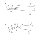
- FIG. 1 is a plan view showing a starboard of an aircraft according to a first embodiment.
- A is a figure which shows the state in which the flap of the aircraft was accommodated.
- B is a figure which shows the state by which the flap was expand
- FIG. 1 is a figure which shows the protrusion member of 1st Embodiment.
- B is a figure which shows the protrusion member which makes angle (theta) with respect to the axis direction D1 in the reverse direction to the protrusion member of (a). It is a graph which shows the relationship with the sound pressure level evaluated from the wind tunnel test result using the wind tunnel test model of an aircraft.
- a flap 3 is provided on the trailing edge 1A of the main wing 1 of the aircraft of the first embodiment shown in FIG.
- the main wing 1 includes a main wing 2 on which a flap 3 can be accommodated and deployed, and a flap 3 which is a high lift device.
- the flap 3 generates high lift by being deployed from the main wing 2 as shown in FIG. 1 during low speed flight such as takeoff and landing.
- the flap 3 is accommodated in the main wing 2 when cruising at a high speed other than during low-speed flight.
- the flap 3 includes an outboard flap 31 positioned on the wing tip 1B side of the main wing 1 and an inboard flap 32 positioned on the fuselage 4 side where the main wing 1 is provided.
- the outboard flap 31 and the inboard flap 32 are collectively referred to as a flap 3.
- the outboard flap 31 and the inboard flap 32 are simultaneously deployed and stored at the same time.
- a gap S1 between the outboard flap 31 and the inboard flap 32 is sealed with a rubber seal (not shown).
- the direction along the axis (one-dot chain line) set on the fuselage 4 is defined as the machine direction D1.
- the nose direction D1 the nose 41 side of the aircraft is referred to as “front”, and the tail side is referred to as “rear”.
- the fuselage 4 side in the span direction of the main wing 1 is referred to as an inner flange side, and the opposite side is referred to as an outer flange side.
- the upper surface side that is the suction surface of the main wing 1 is referred to as “upper”
- the lower surface side that is the pressure surface of the main wing 1 is referred to as “lower”.
- front is “FWD”
- rear is “AFT”
- upper is “UPR”
- lower is “LWR”
- inner side is “INB”
- outer side Is represented by “OTB”.
- the flap 3 is stored in the storage unit 21 prepared in the main wing 2 as shown in FIG. 2A when the aircraft cruises at a high speed. At that time, the flap 3 is integrated with the main wing 2 and constitutes the trailing edge 1A of the main wing 1. The lower surface 302 of the flap 3 is entirely exposed below the main wing 2 during storage.
- the flap 3 is deployed rearward and downward by being driven by an actuator (not shown). At this time, the flap 3 is guided by a rail (not shown).
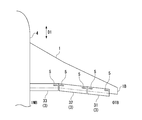
- FIG. 2 (b) shows a state in which the flap 3 is deployed to the flap position at the time of landing. At this time, since the entire flap 3 is exposed from the main wing 2, the area of the main wing 1 is enlarged. A gap S2 is provided between the leading edge 3A of the flap 3 and the trailing edge 2A of the main wing 2.
- the air flow F from the lower surface 102 side of the main wing 1 is squeezed by the gap S2 and flows into the upper surface 301 side of the flap 3 at a high speed, as shown by a one-dot chain line in FIG. . Because of this, and because the angle of attack is given to the flap 3, the difference in flow velocity between the upper surface 301 side and the lower surface 302 side of the flap 3 is large. Therefore, a large pressure difference corresponding to the flow velocity difference is obtained, which can contribute to the generation of high lift.
- the flap 3 has a wing tip 40 that is placed in an air flow when in the deployed state.
- the wing tip 40 corresponds to an end portion of the outer side OTB of the outboard flap 31 and has an end face with a predetermined area.
- a blade tip vortex 40 ⁇ / b> V is generated by an airflow that wraps around from the lower surface 302 side to the upper surface 301 side of the flap 3 due to the pressure difference.
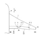
- the blade tip vortex 40V will be described with reference to FIG. 3 showing the basic form of the flap 3 (the form in which the vortex generator according to the present invention is not provided).
- the vortex generated at the leading edge 3 ⁇ / b> A of the blade tip 40 takes a course on the upper surface 301 side and the lower surface 302 side of the flap 3.
- the upper vortex 41V and the lower vortex 42V each flow backward while drawing a spiral in a direction from the lower surface 302 side to the upper surface 301 side.
- the lower vortex 42V that gradually moves upward and the upper vortex 41V merge.
- the upper vortex 41V, the lower vortex 42V, and the vortex 43V after they merge together are collectively referred to as a blade tip vortex 40V.
- the end portion of the inner side INB of the inboard flap 32 (FIG. 1) is close to the body 4, and the gap S1 between the inboard flap 32 and the outboard flap 31 is closed with a seal. ing. Therefore, a wing tip vortex does not occur at the both end portions of the inboard flap 32 and the end portion of the inner side INB of the outboard flap, or even if it occurs.
- the pressure of the airflow forming the tip vortex 40V generated at the tip 40 of the flap 3 fluctuates temporally and spatially, and the pressure fluctuation becomes sound on the surface of the flap 3 and diffuses to the surroundings.
- the diffused sound becomes a source of noise.
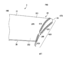
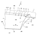
- the flap 3 has a vortex generator 50 as a noise reduction device close to the tip 40 of the upper surface 301 as shown in FIGS. Prepared.
- the flap 3 includes a vortex generator 50 and a flap body 8 in which the vortex generator 50 is provided.
- Each component of the flap 3 can be formed using an appropriate material such as metal or fiber reinforced resin.
- the flap body 8 includes a plurality of ribs arranged along the axis direction D1, a front spar that connects the front ends of the ribs, and a rear spar that connects the rear ends of the ribs. It has a box structure with an upper skin and a lower skin.
- the flap body 8 has a shape in which the dimension in the span direction of the main wing 1 is longer than the dimension in the machine axis direction D1, and the cross section is formed in a wing shape.
- End ribs 80 are respectively disposed at both ends of the flap body 8.
- An end surface 81 of the flap body 8 is formed by the end rib 80.
- the inner wall 21 ⁇ / b> A formed in the storage portion 21 of the main wing 2 faces the end surface 81.
- the end surface 81 of the outer side OTB of the outboard flap 31 of this embodiment forms a predetermined angle with respect to the machine axis direction D1, but may be formed in parallel with the machine axis direction D1.
- the configuration of the vortex generator 50 that reduces noise by generating vortices that interfere with the blade tip vortex 40V will be described.
- the vortex generator 50 is provided at the blade tip 40 of the flap body 8 so as to protrude from the upper surface 301 in the out-of-plane direction, and is a rectangular and plate-like shape having a predetermined angle ⁇ when viewed from the upper surface with respect to the axis direction D1.
- a protruding member 5 is provided. This angle ⁇ (FIG. 5) is about 20 ° as an example.
- the vortex generator 50 of this embodiment includes a plurality of protruding members 5. Of course, the vortex generator 50 may be constituted by one protruding member 5. All the protruding members 5 form a predetermined angle in the same direction with respect to the machine direction D1 and extend by a predetermined length.
- protruding members 5 are arranged at a predetermined interval in the span direction D2 (blade width) of the flap 3.
- the protruding members 5 do not necessarily have to be arranged at equal intervals. Further, the protruding members 5 do not necessarily have the same height, the same angle ⁇ , and the same length.
- the positions of the plurality of protruding members 5 in the cord direction D3 may not be unified.
- the plurality of protruding members 5 can be arranged while shifting the position in the front-rear direction while leaving an interval in the span direction D2.
- the protruding members 5 can be arranged so as to form a plurality of rows.
- the first row of protruding members 5 can be arranged near the front edge 3 ⁇ / b> A of the flap 3, and the second row of protruding members 5 can be arranged behind the protruding members 5.
- the protruding member 5 has a front end 51 located on the front side and a rear end 52 located on the rear side. The front end 51 is disposed in the vicinity of the front edge 3 ⁇ / b> A of the flap body 8.
- the protruding member 5 forms a predetermined angle when viewed from the upper surface with respect to the machine direction D1 so as to approach the side edge 301A of the upper surface 301 from the front end 51 toward the rear end 52.
- the rotation direction of the vortex 5V generated by the vortex generator 50 is the same as the rotation direction of the blade tip vortex 40V described later.
- the protruding member 5 of the present embodiment is a protrusion formed in a rectangular cross section over the entire length extending from the front end 51 to the rear end 52.
- the present invention is not limited thereto, and the form of the protruding member 5 is appropriately set. Can be determined.
- the protruding member 5 may be formed in a triangular shape when viewed from the span direction D2, or may be formed in a semicircular shape when viewed from the span direction D2.
- the protruding member 5 is exposed from the main wing 2 over the entire length.
- FIG. 4 when cruising, as shown in FIG.
- the flap 3 is housed in the main wing 2, and the rear end 52 of the projecting member 5 is positioned in front of the rear edge 2 ⁇ / b> A of the main wing 2. The whole is hidden in the main wing 2.
- the protruding member 5 is exposed to the airflow when the flap 3 is deployed, and exhibits a noise reduction effect. Note that there may be both a case where the protruding member 5 is hidden by the main wing 2 and a case where the protruding member 5 is not hidden at the time of takeoff or at an intermediate steering angle.
- the projecting member 5 is not hidden by the main wing 2 and a part of the projecting member 5 is exposed, there is also an air flow passing through the slot between the main wing 2 and the flap 3, and in this case By configuring so that the protruding member 5 is exposed at the time of takeoff, noise reduction can be brought about.
- the projecting member 5 When hidden by the main wing 2, the projecting member 5 is disposed in a space S ⁇ b> 3 between the upper surface 301 of the flap 3 and the wall 21 ⁇ / b> B of the storage portion 21 prepared in the main wing 2.
- the protruding member 5 When the flap 3 is deployed to a predetermined takeoff position, the protruding member 5 may be exposed from the main wing 2 or may be disposed in the space S3.
- the protruding member 5 is formed at a predetermined height so as to be accommodated in the space S3.
- a predetermined clearance is set between the upper end of the protruding member 5 and the wall 21 ⁇ / b> B of the storage portion 21. Thereby, it can avoid that the protrusion member 5 interferes with a main wing
- the boundary generated on the surface of the flap body 8 on which the protruding member 5 is installed is preferable that the thickness be at least twice the thickness of the layer.
- the height of the protruding member 5 from the upper surface 301 can be appropriately determined as long as it does not interfere with the main wing 2 or the like.
- the relationship between the length and height of the protruding member 5 is preferably L / h> 1, where L is the length and h is the height. More preferably, L / h is 3 to 10. If L / h is too small, the generated vortex 5V becomes weak, so that the noise reduction effect obtained by causing the vortex 5V to interfere with the blade tip vortex 40V becomes small. On the other hand, if L / h is too large, the generated vortex 5V becomes too strong and becomes a new sound source, or aerodynamic performance deteriorates.
- the angle ⁇ (FIG. 5) with respect to the axis direction D1 of the protruding member 5 can be determined as appropriate as long as an appropriate vortex 5V that interferes with the blade tip vortex 40V can be generated.
- the angle ⁇ of the projecting member 5 with respect to the machine axis direction D1 is 10 ° to 30 °. If the angle ⁇ is smaller than the above-mentioned angle range, the generated vortex 5V becomes weak, so that the noise reduction effect obtained by causing the vortex 5V to interfere with the blade tip vortex 40V becomes small. If the angle ⁇ is larger than the above-mentioned angle range, the generated vortex 5V becomes too strong and becomes a new sound source, or the aerodynamic performance is lowered.
- the optimum angle ⁇ at which an excellent noise reduction effect was confirmed in a wind tunnel test described later was 20 °.
- the interval (pitch) P (FIG. 5) between the adjacent protruding members 5 can be determined as appropriate, but is preferably 2 to 10 as a ratio (P / h) to the height h. If it is the space
- the projecting member 5 can be formed integrally with the flap body 8 when the flap body 8 is manufactured, or the projecting member 5 manufactured separately from the flap body 8 can be appropriately bonded and fastened to the upper surface 301 of the flap body 8. It can also be joined by a method.
- the vortex generating portion 50 having the protruding member 5 has a chord direction D3 in which a lower wing tip vortex 42V, which will be described later, faces upward and merges with an upper wing tip vortex 41V. It is preferable that it is located before the position. Therefore, in the cord direction D3, the front end 51 of the protruding member 5 is located in the range of 0% to 60% of the cord length CL (blade chord length) of the flap body 8 from the front edge 3A of the flap body 8. preferable.
- the front end 51 of the protruding member 5 of the present embodiment is separated from the front edge 3A by about 10% of the cord length CL of the flap body 8 in the cord direction D3.
- the vortex generator 50 having the protruding member 5 is disposed in the region R (FIG. 5) from the position of the adjacent side edge 301A to the position separated by the cord length CL in the span direction D2. Is preferred.
- the pressure fluctuation of the air flow due to the blade tip vortex 40V over the region R is remarkably large, and a noise is generated in this region R. Therefore, by providing the vortex generator 50 at the corresponding position, the blade tip vortex 40V The resulting noise can be reliably reduced.
- the leading protruding member 5 closest to the side edge 301A in the arrangement direction of the protruding members 5 (span direction D2) is the side edge 301A. It is preferable to arrange the projecting members 5 at a predetermined pitch P from the projecting members 5.
- the noise reduction effect by the flap 3 of this embodiment is demonstrated.
- noise is generated by the following mechanism. That is, the pressure of the airflow that forms the tip vortex 40V generated at the tip 40 of the flap 3 fluctuates temporally and spatially.
- the pressure fluctuation due to the blade tip vortex 40V becomes sound on the surface of the upper surface of the flap 3, and diffuses to the surroundings. The diffused sound becomes a source of noise.
- the upper direction of the flap 3 is an empty direction, there is no person. In reality, noise is a problem in the downward direction of the flap 3 where a person who receives noise may exist. Therefore, if the noise in the downward direction of the flap 3 (the lower side of the airplane) is reduced, the noise is reduced.
- the blade tip vortex 40V generated at the blade tip 40 of the flap 3 collides with the vortex 5V generated in the vortex generator 50 and becomes a set of a plurality of vortices.
- a set of these vortices is dispersed in the span direction of the flap 3 and away from the blade tip 40 of the flap 3. These dispersed vortices generate sound (noise) on the upper surface of the flap 3.
- the blade tip vortex 40V generated at the blade tip 40 of the flap 3 becomes sound (noise) as it is on the upper surface of the flap 3.
- the center of the position where the sound is generated is closer to the blade tip 40 of the flap 3 as compared with the center of the position where the sound is generated by the dispersed vortex.
- the noise below the flap 3 via the blade tip 40 of the flap 3 is reduced. That is, the noise on the lower side of the aircraft is reduced when the vortex generator 50 is provided.
- the blade tip vortex 40V generated at the blade tip 40 of the flap 3 is caught in the vortex 5V generated by the vortex generating part 50 and away from the surface of the upper surface of the flap 3. More specifically, the wing tip vortex 40V and the vortex 5V merge to cause the wing tip vortex 40V and the vortex 5V to rotate from a predetermined center as if they were planets. Is kept away from the upper surface of the flap 3. Thereby, the pressure fluctuation of the airflow flowing on the upper surface of the flap 3 can be reduced to reduce noise.
- a general vortex generator (Vortex Generator) is arranged in the span direction near the leading edge of the main wing or near the control surface, and suppresses separation of the boundary layer due to shock waves during high-speed flight, etc., and aerodynamics that suppress deterioration of vibration and rudder effectiveness Used as a device.
- This general vortex generator is disposed in a wide range in the span direction of the flap, and is also used as a device for improving aerodynamic characteristics by suppressing separation on the flap at low speed.
- the vortex generator 50 according to the present invention is generally used in that the blade tip vortex 40V is separated from the surface of the upper surface of the flap 3 and exhibits a noise reduction effect.
- the vortex generator is also different in action and effect. More specifically, the operation of the vortex generator 50 (projecting member 5) will be described.
- the protruding member 5 generates a vortex 5V that interferes with the blade tip vortex 40V.
- the air flow F ⁇ b> 1 flowing into the flap body 8 from the front to the rear is indicated by a straight arrow.
- the air flow F1 is parallel to the machine axis direction D1, and the protruding member 5 forms a predetermined angle with respect to the air flow F1.
- the air flow F1 flows into the projecting member 5, and a pressure difference is generated between the left surface side and the right surface side of the projecting member 5, whereby a vortex 5V indicated by a curved arrow is generated in the rotational direction of the arrow.
- the direction of the vortex 5V is represented by a counterclockwise arrow (counterclockwise).
- the vortex 5V flows backward while rotating spirally in the direction of the right screw (FIG. 8A).
- the direction of rotation of the vortex 5V is the same as the direction of rotation of the blade tip vortex 40V generated in the direction of turning from the lower surface 302 to the upper surface 301 at the blade tip 40.
- the generated vortex 5V follows the projecting member 5 and moves toward the side edge 301A as it moves backward (see the broken line arrow).
- the vortex 5V is generated from each of the protruding members 5 arranged on the upper surface 301 of the blade tip 40.
- the vortex 5V generated from each of the projecting members 5 and moved to the side edge 301A side interferes with the upper blade tip vortex 41V and becomes a plurality of vortices.
- a set of these vortices is dispersed in the span direction of the flap 3 and away from the blade tip 40 of the flap 3. Since the center of the position where the sound generated by the dispersed vortex is generated is further away from the blade tip 40 of the flap 3, the noise below the flap 3 via the blade tip 40 of the flap 3 is reduced. That is, when the vortex generator 50 is provided, the noise on the lower side of the aircraft is reduced.
- the vortex 5V including the upper blade tip vortex 41V further flows in the lower blade tip vortex 42V and flows backward.
- a single path F2 through which the upper blade tip vortex 41V and the lower blade tip vortex 42V flow together is shown. This is indicated by a chain line arrow.
- the path F2 is substantially along the upper surface 301 of the flap body 8, whereas the path of the vortex 5V is away from the upper surface 301 of the flap body 8 (FIG. 8B). That is, the upper wing tip vortex 41V and the lower wing tip vortex 42V are pulled up from the initial course F2 while being wound by the vortex 5V, and thus move away from the upper surface 301 of the flap body 8.
- the upper vortex tip vortex 41V is dispersed into a plurality of vortices by causing the vortex 5V generated by the vortex generator 50 to interfere, and the lower noise of the flap 3 via the wing tip 40 of the flap 3 is dispersed.
- the upper blade tip vortex 41V and the lower blade tip vortex 42V that merges with the upper blade tip vortex 42V are wound into the vortex 5V, so that the blade tip vortex 40 is moved away from the surface of the flap 3, and The fluctuation is reduced and the generated noise itself is also reduced.
- the protruding member 5 of the present embodiment is located on the upper surface 301 of the flap 3 before the joining position of the upper blade tip vortex 41V and the lower blade tip vortex 42V, and near the front edge 3A of the flap 3.
- the vortex 5V generated by the projecting member 5 interferes with the upper blade tip vortex 41V at an early stage from the generation at the front edge 3A of the flap 3. Due to the interference by the vortex 5V, the upper blade tip vortex 41V is separated from the surface of the flap 3 and is caught in the vortex 5V.
- the lower wing tip vortex 42V joins the vortex.
- the blade tip vortex 41V is separated from the surface of the flap 3 early due to interference by the vortex 5V, and accordingly, on the surface of the upper surface of the flap 3 accordingly. Pressure fluctuation is further reduced, and noise can be further reduced.
- the protruding member 5 is a small piece that occupies a small area of the upper surface 301 of the flap 3 and is lightweight, the weight of the flap 3 is hardly increased. Further, since the protruding member 5 is hidden by the main wing 2 when the flap 3 is stored, it does not affect the aerodynamic performance during cruising.
- FIG. 9A shows the protruding member 5 of the present embodiment
- FIG. 9B shows a protruding member 15 having a predetermined angle ⁇ opposite to the protruding member 5 of FIG. 9A. Is shown.
- the projecting member 15 shown in FIG. 9B forms an angle ⁇ with respect to the machine direction D1 so as to move away from the side edge 301A of the upper surface 301 from the front end 151 toward the rear end 152.
- the rear end 152 of the protruding member 15 is located on the side farther from the side edge 301A than the virtual line VL.
- the air flow F1 flows into the projecting member 15 in parallel to the machine direction D1, and is turned by the projecting member 15, so that a vortex 15V indicated by a curved arrow is generated in the rotational direction of the arrow (clockwise). Contrary to the vortex 5V generated by the protruding member 5 in FIG. 9A, the vortex 15V flows backward while following the protruding member 15 while spirally rotating in the direction of the left screw (broken arrow) reference). The direction of rotation of the vortex 15V is opposite to that of the wing tip vortex 40V generated in the direction of turning from the lower surface 302 to the upper surface 301 at the wing tip 40. When the vortex 15V generated from the protruding member 15 interferes with the upper wing tip vortex 41V, the energy of the upper wing tip vortex 41V becomes rather large.
- the vortex 15V is pressed against the upper surface 301 of the flap body 8 without involving the blade tip vortex 40V.
- the tip vortex 40V is held on the upper surface 301 of the flap body 8.
- FIG. 10 shows the relationship between the frequency converted into the actual machine scale and the sound pressure level, and the sound pressure level (SPL; Sound Pressure Level) confirmed for the flap 3 of the first embodiment having the protruding member 5 is circled ( ⁇ ). Is plotted. Moreover, the sound pressure level confirmed about the flap (FIG. 3) which does not have the protrusion member 5 is plotted by the square ( ⁇ ).
- FIG. 11 shows a comparison between the sound pressure level of the flap 3 of the first embodiment having the protruding member 5 and the sound pressure level of the flap (FIG. 3) not having the protruding member 5. In both cases, the measurement location was directly under the aircraft.
- the evaluation method is as follows. (1) Noise data only in the vicinity of the flap was extracted by sound source exploration measurement using a microphone array.
- SPL SPL model + 60log (U / U model ) + 20log (L / L model ) -20log (R / R model )
- Scale effect Lmodel / L 0.231 The wind tunnel test model is 23.1% of the actual model.
- Speed dependence Umodel / U 0.791 The wind speed of the wind tunnel test is 53m / s.
- the actual machine is assumed to be 67m / s.
- the wind tunnel test measurement position is 1.1m below the model. The actual machine is assumed to have an altitude of 120m.
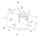
- FIG. 12 shows an example in which the protruding member 5 is installed on the upper surface 301 of the flap body 8 using the fastener 87.
- the protruding member 5 includes a pedestal 53 in which a plurality of holes 531 to 534 into which the fasteners 87 are inserted is formed, and a protrusion 54 that rises from the pedestal 53.
- the pedestal 53 is formed substantially symmetrically on both sides of the protrusion 54.
- the protruding member 5 is fastened to the flap body 8 by a fastener 87.
- a fastener 87 As the fastener 87, a rivet or a bolt can be used.
- the flap body 8 includes an installation portion 85 that protrudes from the upper surface 301 of the wing tip 40 and can be provided with the protruding member 5. As many installation parts 85 as the plurality of projecting members 5 are disposed at positions corresponding to the projecting members 5. A region on the flap body 8 where the pedestal 53 is disposed is indicated by a two-dot chain line. Each installation portion 85 has a plurality of fastener insertion portions 851 to 854 that are disposed in the vicinity of the front edge 3A of the flap body 8 and into which the fasteners 87 are inserted.
- the fastener insertion portions 851 and 852 correspond to one side of the pedestal 53 of the projecting member 5, and among them, the fastener insertion portion 851 is located on the front side, and the fastener insertion portion 852 is located on the rear side.
- the fastener insertion portion 852 is located closer to the side edge 301A than the virtual line VL passing through the fastener insertion portion 851 and parallel to the machine axis direction D1.
- the positional relationship of the fastener insertion portions 853 and 854 corresponding to the other side of the pedestal 53 of the protruding member 5 is the same as described above.
- the existing flap that does not include the protruding member 5 can also be equipped with the protruding member 5 by providing the installation portion 85 and fastening the pedestal 53 and the flap of the protruding member 5 with the fastener 87.
- the projecting member 5 can be detachably provided on the flap body 8, so that maintenance such as replacement and repair is improved.
- a larger number of fasteners 87 can be used.
- three flaps 31, 32, and 33 are arranged on the starboard side and the port side of the aircraft, respectively.
- a predetermined gap exists between the flaps 31 and 32 and the flaps 32 and 33, and a blade tip vortex similar to that of the first embodiment is generated from these gaps.
- the protruding member 5 is also provided at the end portion of the inner side INB of the outboard flap 31.
- projecting members 5 are also provided at the end of the outer side OTB and the end of the inner side INB of the middle board flap 32.
- the protruding member 5 is provided at the end of the outer side OTB of the inboard flap 33. Note that the same configuration can be made when flaps (outboard flaps, inboard flaps) are arranged on the starboard and port side of the aircraft, and a gap exists between these flaps. The same applies when four or more flaps are arranged.
- the present invention can be applied even if there is no gap between the flaps. That is, when only the outboard flap 31 is developed out of the outboard flap 31, the middle board flap 32, and the inboard flap 33, the end of the inner side INB of the outboard flap 31 protrudes in the air current, and the wing Corresponds to the tip of a wing that generates an end vortex.
- the end of the outer side OTB of the middle board flap 32 or the inboard flap 33 also protrudes in the air current and generates the blade tip vortex 40V. It corresponds to the end. Therefore, it is preferable to dispose the protruding members 5 at the blade tips to reduce noise caused by the blade tip vortex generated at the blade tips.
- the tip vortex 40V is generated in the same direction as the end of the outer side OTB such as the outboard flap 31 (wing end 40 in FIG. 7). Therefore, the predetermined angle ⁇ of the projecting member 5 that generates the vortex 5V that interferes with the blade tip vortex 40V is the same as the angle ⁇ of the projecting member 5 located at the end of the outer board side OTB of the outboard flap 31.
- the protruding member 5 located on the outer side OTB of the middle board flap 32 or the inboard flap 33 provides the same operational effects as the protruding member 5 located on the outer side OTB of the outboard flap 31 described in the first embodiment. Therefore, the description about it is abbreviate
- the inner wing side end 40INB of the outboard flap 31 or the middle board flap 32 is opposite to the tip vortex 40VOTB generated at the outer ridge side end 40OTB shown in FIG. 14B.
- Directional tip vortex 40VINB is produced.
- the direction of the vortex capable of interfering with the blade tip vortex 40VINB is also opposite to the direction of the vortex 5VOTB generated by the outer flange side protruding member 5OTB. Therefore, the protruding member 5INB of the end 40INB is The protruding member 5OTB is disposed at an angle ⁇ opposite to that of the protruding member 5OTB.
- the outer flange-side protruding member 5OTB and the inner flange-side protruding member 5INB have a predetermined angle ⁇ in the same direction with respect to the virtual line VL. That is, the rear end 52 of the inner flange side protruding member 5INB is positioned closer to the side edge 301A of the end portion 40INB than the virtual line VL passing through the front end 51 of the inner flange side protruding member 5INB and parallel to the machine axis direction D1. is doing.
- FIG. 15 shows a modification of the present invention.
- outboard flap 31 and the inboard flap 32 described above are arranged adjacent to each other. However, as shown in FIG. 15, the outboard flap 31 and the inboard flap 32 are arranged at a predetermined interval S4. Another member may be disposed between the two.
- the protruding members 5 are provided so as to protrude at least on the upper surface of the outer blade side blade tip.
- the protrusion member 5 can also be provided only about some of the some flaps with which the aircraft was equipped.
- the present invention is not limited to the above-described embodiment, and various forms can be implemented without departing from the gist of the present invention, and the feasible range belongs to the technical scope of the present invention.
- the present invention can be applied to an appropriate type of flap such as a throated flap or a fowler flap.
- a wing having a wing member having an end surface at the wing tip for example, a wing of an aircraft main wing
- the present invention can be applied to an end or a windmill.
- the end face may have not only a planar shape but also various shapes such as a concave shape and a convex shape.
- the vortex generating part has the protruding member.
- the second vortex in the same rotational direction as the first vortex generated from the blade tip is generated from the fluid flowing in the blade length direction of the wing-like member.
- Any vortex generating part to be generated is provided in a region close to the blade tip on the upper surface of the wing-like member and belongs to the technical scope of the present invention.
Abstract
【課題】フラップなどの翼の翼端渦に起因する騒音を低減すること。 【解決手段】航空機のフラップ3は、母翼2に対して展開可能に設けられるフラップ本体8と、フラップ本体8のスパン方向D2の少なくとも外舷側OTBの端部40における上面301に突設されていて、航空機の機軸方向D1に対して所定の角度をなす突出部材5を有する渦発生部50とを備えている。突出部材5の前端51を通り機軸方向D1と平行な仮想線VLよりも、突出部材5の後端52が、フラップ本体8のスパン方向D2の端部40における側端縁301Aに近接する側に位置している。
Description
本発明は、航空機に備えられるフラップ等に用いられる翼に関する。また、本発明は、航空機に備えられるフラップおよび当該航空機に関する。
航空機の主翼の後縁には、高揚力装置としてのフラップが備えられている。フラップは、離着陸時に後方かつ下方に向けて展開されることにより、必要な揚力を発生させる。
主翼からフラップが展開されていると、フラップの翼端で翼端渦が生じる。その翼端渦は、フラップの上面に流れ、フラップ表面でその渦に起因する圧力変動から騒音が発生する。航空機に備えられるフラップに限らず、流体との相互作用によって効率よく揚力を得られるような形状をした物体である翼は、上記のように翼端渦に起因する騒音が発生する。
特許文献1には、そのような騒音を低減するため、フラップ本体の先端部の前縁部の上面側に、先端部の上面に沿う流れを剥離させる流れ抑制部を設けた技術が開示されている。
すなわち、特許文献1に開示された技術は、フラップ本体の先端部の上面に沿う流れを剥離させてフラップ端での揚力を落とすことによって、フラップ端の渦を弱めて騒音を低減している。
航空機に備えられるフラップに限らず、翼を用いる様々な技術分野において、翼端渦に起因する騒音を低減するための新たな技術が求められている。
本発明は、翼の翼端渦に起因する騒音を低減することのできる翼、フラップおよび航空機を提供することを目的とする。
上記課題を解決するため、本発明の一形態に係る翼は、翼端に端面を有する翼状部材と、前記翼状部材の上面で前記翼端に近接する領域に設けられ、前記翼状部材の翼長方向に流れる流体から、前記翼端より発生する第1の渦と同じ回転方向の第2の渦を発生させる渦発生部とを具備する。
本発明の一形態に係る翼では、渦発生部が翼状部材の上面で翼端に近接する領域に設けられているので、第2の渦は第1の渦とぶつかる。第2の渦は第1の渦と同じ回転方向であるので、これにより第1の渦は複数の渦の集合となり第1の渦の領域より広い領域にこれらの渦が分散する。従って、翼状部材の上面の表面でこれらの渦による圧力変動により発生する音のうち翼状部材の翼端を通って下方に向かう量が減る。また、第2の渦は第1の渦と同じ回転方向であるので、第2の渦が第1の渦にぶつかると第1の渦および第2の渦が所定の中心からいわば衛星のように回転し、第1の渦が翼状部材の上面の表面より離間する方向に向かう。従って、翼状部材の上面の表面での第1の渦による圧力変動が小さくなり、その表面で発生する音が小さくなる。この結果、翼の翼端渦に起因する騒音を低減することができる。
本発明の一形態に係る翼では、前記渦発生部は、前記流体が流れる方向に対して所定の角度をなし、前記第2の渦を発生させる突出部材を有することが好ましい。これにより、渦発生部をシンプルで耐久性を有するものとし、軽量化も図ることができる。
本発明の一形態に係る翼では、前記突出部材は、前記翼状部材の前縁から前記翼状部材の後縁に向かうに従って前記翼端に近づくように設けられていることが好ましい。これにより、突出部材を例えば板状などの非常にシンプルな形状としつつ翼端より発生する第1の渦と同じ回転方向の第2の渦を発生させることができる。
本発明の一形態に係る翼では、前記渦発生部が設けられた領域は、前記翼状部材の前縁の近くにあることが好ましい。また、前記渦発生部が設けられた領域は、前記翼状部材の前記翼端の位置から、前記翼状部材の翼長方向に前記翼状部材のコード長だけ離れた範囲にあることが好ましい。更に、前記渦発生部は、前記翼状部材の翼長方向に配列された複数の前記突出部材を有することが好ましい。これにより、より効率よく翼の翼端渦に起因する騒音を低減することができる。
本発明の一形態に係るフラップは、航空機の母翼に対して展開可能に設けられるフラップ本体と、前記フラップ本体の上面で当該フラップ本体の翼端に近接する領域に設けられ、前記航空機の機軸方向に流れる気体から、前記翼端より発生する第1の渦と同じ回転方向の第2の渦を発生させる渦発生部とを具備する。これにより、フラップ本体の翼端渦に起因する騒音を低減することができる。
本発明の一形態に係るフラップでは、前記渦発生部は、前記気体が流れる方向に対して所定の角度をなし、前記第2の渦を発生させる突出部材を有することが好ましい。これにより、渦発生部をシンプルで耐久性を有するものとし、軽量化も図ることができる。
本発明の一形態に係るフラップでは、前記突出部材は、前記突出部材の前縁を通り前記機軸方向と平行な仮想線よりも、前記突出部材の後縁が、前記フラップ本体の前記スパン方向の前記翼端に近接する側に位置することが好ましい。これにより、突出部材を非常にシンプルな形状としつつ翼端より発生する第1の渦と同じ回転方向の第2の渦を発生させることができる。
本発明の一形態に係るフラップでは、前記渦発生部は、前記フラップ本体の前記翼端の位置から、前記スパン方向において前記フラップ本体のコード長だけ離れた位置までの領域に配置されていることが好ましい、また、前記渦発生部は、複数の前記突出部材を備え、前記複数の突出部材は、前記スパン方向に配列されていることが好ましい。これにより、より効率よくフラップの翼端渦に起因する騒音を低減することができる。
本発明の一形態に係るフラップでは、前記フラップ本体が展開された状態のとき、前記突出部材が前記母翼から露出し、前記フラップ本体が前記母翼に収納された状態のとき、前記突出部材が前記母翼に隠れるように、前記突出部材は、前記フラップ本体の前縁の近くに配置されていることが好ましい。これにより、突出部材が低速飛行時以外の高速での巡航時に悪影響を与えることはない。
本発明の一形態に係る航空機は、上記形態のフラップを備える。これにより、少なくとも着陸時の騒音を低減することができる。
本発明の一形態に係る航空機のフラップは、フラップのスパン方向の少なくとも外舷側の端部における上面に、上面から突出するデバイスを設置可能な設置部を備え、設置部は、それぞれにファスナが挿入される2つ以上のファスナ挿入部を備える。ファスナ挿入部のうち、相対的に後方に配置されるファスナ挿入部は、相対的に前方に配置されるファスナ挿入部を通り機軸方向と平行な仮想線よりも、フラップ本体のスパン方向の端部における翼端面に近接する側に位置する。ここで、上面から突出するデバイスとは、本発明に係る渦発生部を構成する突出部材である。
本発明により、フラップなどの翼の翼端渦に起因する騒音を低減することができる。
以下、添付図面を参照しながら、本発明の実施形態について説明する。
〔第1実施形態〕
図1に示す第1実施形態の航空機の主翼1の後縁1Aには、フラップ3が備えられている。
主翼1は、フラップ3が収容かつ展開可能に設けられる母翼2と、高揚力装置であるフラップ3とを備えている。
〔第1実施形態〕
図1に示す第1実施形態の航空機の主翼1の後縁1Aには、フラップ3が備えられている。
主翼1は、フラップ3が収容かつ展開可能に設けられる母翼2と、高揚力装置であるフラップ3とを備えている。
フラップ3は、離着陸時等の低速飛行時に、図1に示すように母翼2から展開されることで高揚力を発生させる。フラップ3は、低速飛行時以外の高速での巡航時には母翼2に収容される。
フラップ3には、主翼1の翼端1B側に位置するアウトボードフラップ31と、主翼1が設けられる胴体4側に位置するインボードフラップ32とがある。これらアウトボードフラップ31およびインボードフラップ32をフラップ3と総称する。
アウトボードフラップ31およびインボードフラップ32は、同時に展開され、同時に収納される。アウトボードフラップ31とインボードフラップ32との間の隙間S1は、ラバーシール(図示を省略)により封止される。
以下では、胴体4に設定された軸線(一点鎖線)に沿った方向のことを機軸方向D1と定義する。機軸方向D1において航空機の機首41側を「前」、尾翼側を「後」というものとする。
また、胴体4の左側および右側のそれぞれにおいて、主翼1のスパン方向における胴体4側を内舷側、その反対側を外舷側というものとする。
さらに、主翼1の負圧面である上面側を「上」、主翼1の正圧面である下面側を「下」というものとする。
さらに、主翼1の負圧面である上面側を「上」、主翼1の正圧面である下面側を「下」というものとする。
なお、図において、「前」を「FWD」、「後」を「AFT」、「上」を「UPR」、「下」を「LWR」、「内舷側」を「INB」、「外舷側」を「OTB」で表すものとする。
フラップ3は、航空機の高速での巡航時には、図2(a)に示すように母翼2に用意された収納部21内に収納されている。そのときフラップ3は母翼2と一体化されており、主翼1の後縁1Aを構成している。収納時にフラップ3の下面302は母翼2の下方に全体的に露出している。
フラップ3は、図示しないアクチュエータにより駆動されることで、後方かつ下方に向けて展開される。このときフラップ3は、図示しないレールによりガイドされる。
図2(b)は、着陸時のフラップ位置にまでフラップ3が展開された状態を示している。このときフラップ3の全体が母翼2から露出しているので主翼1の面積が拡大される。フラップ3の前縁3Aと母翼2の後縁2Aとの間には間隙S2があいている。
フラップ3の展開時には、図2(b)に一点鎖線で示すように、主翼1の下面102側からの気流Fが間隙S2により絞られて、フラップ3の上面301側へと速い速度で流入する。そのことと、フラップ3に迎角が与えられていることにより、フラップ3の上面301側と下面302側との流速差が大きい。そのため、流速差に対応する大きな圧力差が得られるので、高揚力の発生に寄与することができる。
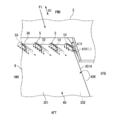
フラップ3は、図1に示すように、展開された状態のとき気流に置かれる翼端40を有している。翼端40は、アウトボードフラップ31の外舷側OTBの端部に該当し、所定の面積の端面を有する。この翼端40では、上述の圧力差によりフラップ3の下面302側から上面301側へと回り込む気流によって翼端渦40Vが生じる。
フラップ3の基本形態(本発明に係る渦発生部が設けられていない形態)を示す図3を参照し、翼端渦40Vについて説明する。
フラップ3の基本形態(本発明に係る渦発生部が設けられていない形態)を示す図3を参照し、翼端渦40Vについて説明する。
図3に示すように、翼端40の前縁3Aで発生した渦は、フラップ3の上面301側と下面302側とに進路をとる。上側の渦41Vと、下側の渦42Vとは、それぞれ、下面302側から上面301側へと向かう向きで螺旋を描きつつ後方へと流れる。そして、次第に上方へと進む下側の渦42Vと、上側の渦41Vとが合流する。上側の渦41V、下側の渦42Vおよびそれらが合流した後の渦43Vを翼端渦40Vと総称する。
本実施形態では、インボードフラップ32(図1)の内舷側INBの端部は胴体4に近接しており、インボードフラップ32とアウトボードフラップ31との間の隙間S1はシールで塞がれている。そのため、インボードフラップ32の両端部およびアウトボードフラップの内舷側INBの端部では翼端渦が生じないか、生じたとしても軽微である。
フラップ3の翼端40で生じる翼端渦40Vを形成する気流の圧力は、時間的および空間的に変動しており、その圧力変動がフラップ3の表面において音となり、周囲へ拡散する。その拡散する音が騒音の発生源となる。
フラップ3が途中まで展開される離陸時と比べて、フラップ3が全体的に露出するように最後まで展開される着陸時は(図2(b))、上面301と下面302との流速差に起因する圧力差が大きくなることで、よりエネルギーが大きい渦となり、より大きな騒音が発生する。しかも、着陸時には、騒音を発生するエンジンの出力が低いので、フラップ3の翼端40からの騒音が顕在化する。
着陸時などの翼端渦40Vに起因する騒音を低減するため、フラップ3は、図4および図5に示すように、騒音低減デバイスとしての渦発生部50を上面301の翼端40に近接して備えている。
フラップ3は、渦発生部50と、渦発生部50が設けられるフラップ本体8とを備えている。フラップ3の各構成要素は、金属や繊維強化樹脂等の適宜な材料を用いて形成することができる。
フラップ本体8は、具体的な図示を省略するが、機軸方向D1に沿って配置される複数のリブと、各リブの前端を連結する前スパーと、各リブの後端を連結する後スパーと、上スキンおよび下スキンを備えたボックス構造となっている。
フラップ本体8は、機軸方向D1の寸法よりも主翼1のスパン方向の寸法が長い形状で、横断面が翼状に形成されている。フラップ本体8の両端部にはそれぞれ、エンドリブ80が配置されている。エンドリブ80によってフラップ本体8の端面81が形成されている。フラップ3の収納時、端面81には、母翼2の収納部21に形成された内壁21Aが対向する。本実施形態のアウトボードフラップ31の外舷側OTBの端面81は、機軸方向D1に対して所定の角度をなしているが、機軸方向D1と平行に形成されていてもよい。
翼端渦40Vに干渉する渦を発生させることで騒音低減を図る渦発生部50の構成について説明する。
翼端渦40Vに干渉する渦を発生させることで騒音低減を図る渦発生部50の構成について説明する。
渦発生部50は、フラップ本体8の翼端40に、上面301から面外方向に突出するように設けられ、機軸方向D1に対して上面から見て所定の角度θをなす矩形で板状の突出部材5を有する。この角度θ(図5)は、一例として、約20°である。
本実施形態の渦発生部50は、複数の突出部材5を備えている。勿論、渦発生部50は、1つの突出部材5により構成されていてもよい。
いずれの突出部材5も機軸方向D1に対して同じ向きに所定の角度をなし、所定の長さだけ延びている。
それらの突出部材5は、フラップ3のスパン方向D2(翼幅)に所定の間隔をおいて配列されている。
突出部材5は、必ずしも等しい間隔をおいて配列されている必要がない。
また、各突出部材5は、必ずしも同じ高さや同じ角度θ、同じ長さでなくてもよい。
本実施形態の渦発生部50は、複数の突出部材5を備えている。勿論、渦発生部50は、1つの突出部材5により構成されていてもよい。
いずれの突出部材5も機軸方向D1に対して同じ向きに所定の角度をなし、所定の長さだけ延びている。
それらの突出部材5は、フラップ3のスパン方向D2(翼幅)に所定の間隔をおいて配列されている。
突出部材5は、必ずしも等しい間隔をおいて配列されている必要がない。
また、各突出部材5は、必ずしも同じ高さや同じ角度θ、同じ長さでなくてもよい。
複数の突出部材5のコード方向D3(図5)における位置は統一されていなくてもよい。例えば、スパン方向D2に間隔をおきつつ、前後互い違いに位置をずらしながら複数の突出部材5を配置することができる。
また、複数の列をなすように突出部材5を配置することもできる。例えば、フラップ3の前縁3Aの付近に1列目の突出部材5を配置し、それらの突出部材5よりも後方に2列目の突出部材5を配置することができる。
図4および図5に示すように、突出部材5は、前方に位置する前端51と、後方に位置する後端52とを有している。
前端51は、フラップ本体8の前縁3Aの近傍に配置されている。
図4および図5に示すように、突出部材5は、前方に位置する前端51と、後方に位置する後端52とを有している。
前端51は、フラップ本体8の前縁3Aの近傍に配置されている。
そして、前端51を通り機軸方向D1と平行な仮想線VL(図5)を設定すると、この仮想線VLよりも、フラップ本体8の上面301の側端縁301Aに近接する側に後端52が位置している。
つまり、突出部材5は、前端51から後端52に向かうにつれて上面301の側端縁301Aに近づくように、機軸方向D1に対して上面から見て所定の角度をなしている。これにより、渦発生部50により発生する渦5Vの回転方向は、後述する翼端渦40Vの回転方向と同じになる。
本実施形態の突出部材5は、前端51から後端52まで延びる長さの全体に亘り、断面矩形状に形成されている突条であるが、これに限らず、突出部材5の形態を適宜に定めることができる。例えば、突出部材5は、スパン方向D2から見たとき三角状に形成されていてもよく、スパン方向D2から見たとき半円状に形成されていてもよい。
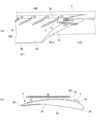
図4に示すようにフラップ3が着陸時の位置まで展開されているとき、突出部材5は全長に亘り母翼2から露出している。
一方、巡航時には、図6に示すように、フラップ3が母翼2に収納され、突出部材5の後端52が母翼2の後縁2Aよりも前方に位置しており、突出部材5の全体が母翼2に隠れている。
突出部材5は、フラップ3が展開されているときに気流に曝され、騒音低減効果を発揮する。
なお、離陸時や中間舵角では突出部材5が母翼2に隠れる場合と隠れない場合の両方がありうる。突出部材5が母翼2に隠れず、突出部材5の一部が露出する場合には、母翼2とフラップ3間のスロットを抜ける気流もあり、気流に曝されるので、この場合には、離陸時などに突出部材5が露出するように構成することで、騒音低減をもたらすことができる。
母翼2に隠れているとき、突出部材5は、フラップ3の上面301と、母翼2に用意された収納部21の壁21Bとの間のスペースS3内に配置されている。
フラップ3が所定の離陸時の位置まで展開されているとき、突出部材5は母翼2から露出していても、スペースS3内に配置されていてもよい。
フラップ3が展開されているとき、母翼2とフラップ3との間に母翼2の下面側からの気流が通り抜けるスロットが形成されているので、突出部材5は、母翼2から露出していなくても、そのスロットを通る気流に曝されることで、騒音低減効果を発揮する。
突出部材5は、スペースS3内に収容されるように、所定の高さに形成されている。
突出部材5は、スペースS3内に収容されるように、所定の高さに形成されている。
突出部材5の上端と収納部21の壁21Bとの間には、所定のクリアランスが設定されている。それによって突出部材5が母翼や周囲の部材(スポイラ等)に干渉することを避けることができる。
突出部材5の上面301からの高さは、後述するように翼端渦40Vに干渉する渦5V(図7)を発生させる必要から、突出部材5の設置されるフラップ本体8の表面に生じる境界層の厚さの2倍以上とするのが好ましい。突出部材5の上面301からの高さは、母翼2等と干渉しない限りにおいて、適宜に定めることができる。
突出部材5の長さと高さとの関係は、長さをL、高さをhとすると、L/h>1であることが好ましい。より好ましくは、L/hが3~10である。L/hが小さ過ぎると、発生する渦5Vが弱くなるので、渦5Vを翼端渦40Vに干渉させることによって得られる騒音低減効果が小さくなる。また、L/hが大き過ぎると、発生する渦5Vが強くなり過ぎて新たな音源となり、あるいは空力性能が低下する。
突出部材5の機軸方向D1に対する角度θ(図5)は、翼端渦40Vに干渉する適切な渦5Vを発生させることができる限りにおいて、適宜に定めることができる。
好ましい突出部材5の機軸方向D1に対する角度θは、10°~30°である。角度θが前述の角度範囲よりも小さいと、発生する渦5Vが弱くなるので、渦5Vを翼端渦40Vに干渉させることによって得られる騒音低減効果が小さくなる。また、角度θが前述の角度範囲よりも大きいと、発生する渦5Vが強くなり過ぎて新たな音源となり、あるいは空力性能が低下する。
後述する風洞試験において優れた騒音低減効果が確認された最適な角度θは20°であった。
後述する風洞試験において優れた騒音低減効果が確認された最適な角度θは20°であった。
隣り合う突出部材5の間の間隔(ピッチ)P(図5)は、適宜に定めることができるが、好ましくは、高さhに対する比率(P/h)として、2~10である。その範囲の間隔であれば、隣り合う突出部材5がそれぞれ発生させた渦5V同士の干渉を抑制することができるので、渦5Vを翼端渦40Vに十分に干渉させることができる。一方、P/hが2より小さいと、隣接する突出部材5で発生する渦5V同士が緩衝し、渦5Vのエネルギーが分散し、渦5Vを翼端渦40Vに十分に干渉させることができなくなる。また、P/hが10より大きいと、各渦5Vを翼端渦40Vに連続的に干渉できなくなり、騒音低減効果が不十分になるおそれがある。
突出部材5は、フラップ本体8の製造時にフラップ本体8と一体に形成することもできるし、フラップ本体8とは別に製作した突出部材5をフラップ本体8の上面301に接着、締結等の適宜な方法で接合することもできる。
フラップ3のコード(翼弦)方向D3(図5)において、突出部材5を有する渦発生部50は、後述する下側翼端渦42Vが上方に向かい、上側翼端渦41Vに合流するコード方向D3の位置よりも前に位置していることが好ましい。そのため、コード方向D3において、突出部材5の前端51が、フラップ本体8の前縁3Aからフラップ本体8のコード長CL(翼弦長)の0%~60%の範囲に位置している状態が好ましい。
本実施形態の突出部材5の前端51は、コード方向D3において、前縁3Aからフラップ本体8のコード長CLの約10%だけ離れている。
本実施形態の突出部材5の前端51は、コード方向D3において、前縁3Aからフラップ本体8のコード長CLの約10%だけ離れている。
また、突出部材5を有する渦発生部50は、隣に位置する側端縁301Aの位置から、スパン方向D2においてコード長CLだけ離れた位置までの領域R(図5)内に配置されることが好ましい。領域Rに亘り翼端渦40Vによる気流の圧力変動が顕著に大きく、この領域Rにおいて騒音となる音が発生するので、そこ対応する位置に渦発生部50を設けることにより、翼端渦40Vに起因する騒音を確実に低減することができる。
本実施形態のように渦発生部50が複数の突出部材5を備える場合は、突出部材5の配列方向(スパン方向D2)において側端縁301Aに最も近い先頭の突出部材5を側端縁301Aのすぐそばに配置し、その突出部材5から所定のピッチPをおいて突出部材5を並べるとよい。
以下、本実施形態のフラップ3による騒音低減効果について説明する。
以下、本実施形態のフラップ3による騒音低減効果について説明する。
フラップ3の上面では、以下のメカニズムで騒音が発生する。つまり、フラップ3の翼端40で生じる翼端渦40Vを形成する気流の圧力は、時間的および空間的に変動している。その翼端渦40Vがフラップ3の上面の表面に流れ込むと、翼端渦40Vによる圧力変動がフラップ3の上面の表面において音となり、周囲へ拡散する。その拡散する音が騒音の発生源となる。
フラップ3の上方向は空の方向であるので、人が存在しない。現実的に騒音が問題となるのは、騒音を受ける人が存在する可能性のあるフラップ3の下方向である。従って、フラップ3の下方向(飛行機の下側)における騒音が小さくなれば、騒音を低減したことになる。
本実施形態では、フラップ3の翼端40で生じる翼端渦40Vは、渦発生部50で発生した渦5Vとぶつかり、複数の渦の集合となる。ここで、翼端渦40Vと渦5Vとの回転方向は同じであるので、フラップ3のスパン方向であってフラップ3の翼端40から離れる方向にこれらの渦の集合が分散する。これら分散した渦によりフラップ3の上面の表面において音(騒音)が発生する。
一方、渦発生部50が設けられていない場合には、フラップ3の翼端40で生じる翼端渦40Vがそのままフラップ3の上面の表面において音(騒音)となる。その音の発生する位置の中心は、上記の分散した渦による音の発生する位置の中心と比べると、フラップ3の翼端40に近くなる。逆にいうと、分散した渦による音の発生する位置の中心は、フラップ3の翼端40からより遠くなるので、フラップ3の翼端40経由でのフラップ3の下側の騒音は小さくなる。つまり、渦発生部50が設けたときに航空機の下側での騒音は小さくなる。
また、渦発生部50を設けたことにより、フラップ3の翼端40で生じる翼端渦40Vは、渦発生部50により発生させた渦5Vに巻き込まれフラップ3の上面の表面から遠ざけられる。具体的には、翼端渦40Vと渦5Vとの合流により、翼端渦40Vと渦5Vとが所定の中心からそれぞれがいわば惑星のように回転して進行し、この結果、翼端渦40Vは、フラップ3の上面の表面から遠ざけられる。これにより、フラップ3の上面の表面を流れる気流の圧力変動を小さくして騒音を減らすことができる。
一般の渦発生装置(Vortex Generator)は、主翼の前縁近くまたは舵面近くのスパン方向に配置され、高速飛行時の衝撃波などによる境界層の剥離を抑え、振動や舵効きの悪化を抑える空力デバイスとして用いられている。また、この一般の渦発生装置は、フラップのスパン方向に幅広い範囲に配置され、同じく低速時のフラップ上の剥離を抑えて空力特性を改善するデバイスとして用いられている。本発明に係る渦発生部50は、空力特性改善を目的とする一般の渦発生装置と異なり、翼端渦40Vをフラップ3の上面の表面から遠ざけることで騒音低減効果を発揮するという点で一般の渦発生装置とは作用・効果も異なる。
より具体的に、渦発生部50(突出部材5)の作用について説明する。
突出部材5は、翼端渦40Vに干渉する渦5Vを発生させる。
より具体的に、渦発生部50(突出部材5)の作用について説明する。
突出部材5は、翼端渦40Vに干渉する渦5Vを発生させる。
図7には、前方から後方に向けてフラップ本体8へと流入する気流F1を直線の矢印で示している。この気流F1は機軸方向D1に平行であり、気流F1に対して突出部材5が所定の角度をなしている。気流F1が突出部材5に流入し、突出部材5の左面側と右面側との間で圧力差が生じることで、曲線の矢印で示す渦5Vが矢印の回転向きに発生する。図7のように後方から見ると、渦5Vの向きは左回り(反時計回り)の矢印で表される。渦5Vは、右ねじの向きで螺旋状に回転しながら後方へと流れていく(図8(a))。この渦5Vの回転の向きは、翼端40で下面302から上面301へと回り込む向きに生じる翼端渦40Vの回転の向きと同様である。発生した渦5Vは、突出部材5に倣い、後方へと進むにつれて側端縁301A側へと移動する(破線矢印参照)。
渦5Vは、翼端40の上面301に配列された突出部材5の各々から発生する。
渦5Vは、翼端40の上面301に配列された突出部材5の各々から発生する。
突出部材5の各々から発生して側端縁301A側へと移動した渦5Vは、上側翼端渦41Vに干渉し、複数の渦となる。ここで、上側翼端渦41Vと渦5Vとの回転方向は同じであるので、フラップ3のスパン方向であってフラップ3の翼端40から離れる方向にこれらの渦の集合が分散する。分散した渦による音の発生する位置の中心は、フラップ3の翼端40からより遠くなるので、フラップ3の翼端40経由でのフラップ3の下側の騒音は小さくなる。つまり、渦発生部50を設けたときに航空機の下側での騒音は小さくなる。
上側翼端渦41Vを巻き込んだ渦5Vは、図8(a)に示すように、さらに下側翼端渦42Vをも巻き込んで後方へと流れる。
上側翼端渦41Vを巻き込んだ渦5Vは、図8(a)に示すように、さらに下側翼端渦42Vをも巻き込んで後方へと流れる。
図8(a)および(b)には、仮に、上側翼端渦41Vが渦5Vにより干渉されないとした場合に、上側翼端渦41Vおよび下側翼端渦42Vが合流して流れる進路F2を一点鎖線の矢印で示している。その進路F2がフラップ本体8の上面301にほぼ沿っているのに対して、渦5Vの進路はフラップ本体8の上面301から離れている(図8(b))。つまり、上側翼端渦41Vおよび下側翼端渦42Vは、渦5Vにより巻き込まれつつ当初の進路F2から引き上げられるので、フラップ本体8の上面301から遠ざかる。これは、翼端渦40Vと渦5Vとの合流により、翼端渦40Vと渦5Vとが所定の中心点からそれぞれがいわば惑星のように回転して進行し、この結果、翼端渦40Vは、フラップ3の上面の表面から遠ざけられるからである。
以上のように、渦発生部50により発生させた渦5Vを干渉させることで、上側翼端渦41Vを複数の渦に分散し、フラップ3の翼端40経由でのフラップ3の下側の騒音は小さくなり、加えて上側翼端渦41Vおよびそれに合流した下側翼端渦42Vを渦5Vに巻き込むことで、翼端渦40がフラップ3の表面から遠ざけられ、フラップ3の表面を流れる気流の圧力変動が小さくなり、発生する騒音自体も小さくなる。
上述したように、本実施形態の突出部材5は、フラップ3の上面301において上側翼端渦41Vと下側翼端渦42Vとの合流位置よりも前であって、フラップ3の前縁3Aの近くに位置しており、突出部材5により発生した渦5Vは、上側翼端渦41Vに対して、フラップ3の前縁3Aにおける発生からの早い段階で干渉する。渦5Vによる干渉によって上側翼端渦41Vはフラップ3の表面から離れて渦5Vに巻き込まれる。その渦流に下側翼端渦42Vが合流する。
突出部材5が前縁3Aの近くに配置されていると、渦5Vによる干渉によって翼端渦41Vがフラップ3の表面から早期に離れることとなるので、その分、フラップ3の上面の表面での圧力変動がより一層減少し、騒音をさらに低減することができる。
本実施形態によれば、フラップ本体8に突出部材5を設けるだけで、低騒音化が特に求められる例えば着陸時の騒音を低減することができる。突出部材5はフラップ3の上面301の僅かな領域を占める小片であって軽量なので、フラップ3の重量を殆ど増加させない。
また、突出部材5は、フラップ3の収納時には母翼2に隠れているため、巡航時の空力性能に影響しない。
また、突出部材5は、フラップ3の収納時には母翼2に隠れているため、巡航時の空力性能に影響しない。
もっとも、突出部材5の一部または全体が、離陸時に母翼2から露出するコード方向D3における位置にあってもよい。その場合にも、気流に突出部材5が与える影響は小さく、離陸時の騒音を突出部材5の作用により低減でき、離陸時における所定の空力性能を実現することができる。
以下、機軸方向D1に対して突出部材5のなす角度θについて説明する。
図9(a)は、本実施形態の突出部材5を示し、図9(b)は、図9(a)の突出部材5とは逆向きに所定の角度θを有している突出部材15を示している。
以下、機軸方向D1に対して突出部材5のなす角度θについて説明する。
図9(a)は、本実施形態の突出部材5を示し、図9(b)は、図9(a)の突出部材5とは逆向きに所定の角度θを有している突出部材15を示している。
図9(b)に示す突出部材15は、前端151から後端152に向かうにつれて上面301の側端縁301Aから離れるように、機軸方向D1に対して角度θをなしている。
前端151を通り機軸方向D1と平行な仮想線VLを設定すると、突出部材15の後端152は、仮想線VLよりも側端縁301Aから離れる側に位置している。
機軸方向D1と平行に気流F1が突出部材15に流入し、突出部材15により転向されることで、曲線の矢印で示す渦15Vが矢印の回転向き(時計回り)に発生する。渦15Vは、図9(a)の突出部材5により発生する渦5Vとは逆に、左ねじの向きで螺旋状に回転しながら、突出部材15に倣いつつ後方へと流れていく(破線矢印参照)。この渦15Vは、翼端40で下面302から上面301へと回り込む向きに生じる翼端渦40Vとは回転の向きが逆である。
突出部材15から発生した渦15Vが上側翼端渦41Vに対して干渉すると、上側翼端渦41Vのエネルギーはむしろ大きくなってしまう。
突出部材15から発生した渦15Vが上側翼端渦41Vに対して干渉すると、上側翼端渦41Vのエネルギーはむしろ大きくなってしまう。
しかも、渦15Vと翼端渦40Vとは回転の向きが逆なので、渦15Vは、翼端渦40Vを巻き込むことなく、フラップ本体8の上面301へと押し付ける。それによって翼端渦40Vがフラップ本体8の上面301に保持される。
以上より、本実施形態の突出部材5とは逆向きに角度θを有する突出部材15により、翼端渦40Vとは逆向きの渦15Vが発生すると、翼端渦40Vによりフラップ3の表面での圧力変動が増大するので、騒音が助長されてしまう。突出部材15によりフラップ3の上面301の渦の強さが増大することは、数値流体力学(Computational Fluid Dynamics ;CFD)シミュレーションによって確認されている。
航空機の風洞試験模型を用いた風洞試験結果を用いて評価した音低減効果について説明する。
航空機の風洞試験模型を用いた風洞試験結果を用いて評価した音低減効果について説明する。
図10は実機スケールに換算した周波数と音圧レベルとの関係し、突出部材5を備えた第1実施形態のフラップ3について確認された音圧レベル(SPL;Sound Pressure Level)を丸(○)でプロットしている。また、突出部材5を備えないフラップ(図3)について確認された音圧レベルを四角(□)でプロットしている。
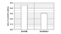
また、図11は突出部材5を備えた第1実施形態のフラップ3の音圧レベルと突出部材5を備えないフラップ(図3)の音圧レベルとを比較したものである。
いずれも測定場所は、航空機の直下とした。
また、評価方法は、以下のとおりである。
(1)マイクロフォンアレイを用いた音源探査計測によりフラップ近傍のみの騒音データを抽出した。
(2)周波数と音圧レベル(SPL)に関して、以下の式でスケール効果、速度補正、距離減衰補正を加えて実機スケールへ換算した。
SPL=SPLmodel+60log(U/Umodel)+20log(L/Lmodel)-20log(R/Rmodel)
ただし、
スケール効果 Lmodel/L 0.231 風洞試験模型は実機の23.1%スケール。
速度依存性 Umodel/U 0.791 風洞試験の風速は53m/s。実機は67m/sと仮定。
距離減衰補正 Rmodel/R 0.00917 風洞試験の計測位置はモデル下方1.1m位置。
実機は高度120mと仮定。
図10及び図11より、基本形態のフラップ(フラップ本体8)に突出部材5を設けると、フラップ騒音のピーク周波数を含む帯域に亘り、かつトータルでも騒音低減効果を得ることができる。
上述した突出部材5の設置形態の一例を示す。
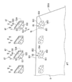
図12は、突出部材5をフラップ本体8の上面301にファスナ87を用いて設置する例を示している。
上述した突出部材5の設置形態の一例を示す。
図12は、突出部材5をフラップ本体8の上面301にファスナ87を用いて設置する例を示している。
突出部材5は、ファスナ87が挿入される複数の孔531~534が形成された台座53と、台座53から起立する突起54とを備えている。台座53は、突起54の両側に略対称に形成されている。
突出部材5は、ファスナ87によりフラップ本体8に締結される。
ファスナ87として、リベットやボルトを採用することができる。
突出部材5は、ファスナ87によりフラップ本体8に締結される。
ファスナ87として、リベットやボルトを採用することができる。
フラップ本体8は、翼端40の上面301から突出していて突出部材5を設置可能な設置部85を備えている。設置部85は、複数の突出部材5と同じ数だけ、突出部材5の各々に対応する位置に配置されている。台座53が配置されるフラップ本体8上の領域を二点鎖線で示している。
各設置部85は、フラップ本体8の前縁3Aの近傍に配置されてファスナ87が挿入される複数のファスナ挿入部851~854を有している。
各設置部85は、フラップ本体8の前縁3Aの近傍に配置されてファスナ87が挿入される複数のファスナ挿入部851~854を有している。
ファスナ挿入部851,852は、突出部材5の台座53の一方側に対応しており、それらのうちファスナ挿入部851は前方に位置し、ファスナ挿入部852は後方に位置している。そして、ファスナ挿入部852は、ファスナ挿入部851を通り機軸方向D1と平行な仮想線VLよりも、側端縁301Aに近接する側に位置している。
突出部材5の台座53の他方側に対応しているファスナ挿入部853,854の位置関係も上記と同様である。
突出部材5の台座53の他方側に対応しているファスナ挿入部853,854の位置関係も上記と同様である。
突出部材5を備えていない既存のフラップにも、設置部85を設け、突出部材5の台座53とフラップとをファスナ87により締結することにより、突出部材5を装備することができる。
ファスナ87にボルトを用いると、突出部材5をフラップ本体8に着脱可能に設けることができるので、交換、修理等のメンテナンス性が向上する。
突出部材5を締結するため、より多くの数のファスナ87を用いることもできる。
〔第2実施形態〕
図13および図14を参照し、本発明の第2実施形態について説明する。
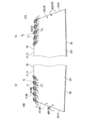
第2実施形態では、図13に示すように、航空機の右舷および左舷のそれぞれに3つのフラップ31、32、33(アウトボードフラップ、ミドルボードフラップ、インボードフラップ)が配置されている。これらフラップ31と32およびフラップ32と33との間には、所定の隙間が存在し、これらの隙間から最初の実施形態と同様の翼端渦が発生する。この第2の実施形態では、アウトボードフラップ31の外舷側OTBの端部に加えて、アウトボードフラップ31の内舷側INBの端部にも突出部材5が設けられている。また、ミドルボードフラップ32の外舷側OTBの端部および内舷側INBの端部にも突出部材5が設けられている。さらに、インボードフラップ33の外舷側OTBの端部に、突出部材5が設けられている。
なお、航空機の右舷および左舷のそれぞれにフラップ(アウトボードフラップ、インボードフラップ)が配置され、これらフラップの間に隙間が存在する場合にも同様に構成することができる。また、4つ以上のフラップが配置されている場合も同様である。
ファスナ87にボルトを用いると、突出部材5をフラップ本体8に着脱可能に設けることができるので、交換、修理等のメンテナンス性が向上する。
突出部材5を締結するため、より多くの数のファスナ87を用いることもできる。
〔第2実施形態〕
図13および図14を参照し、本発明の第2実施形態について説明する。
第2実施形態では、図13に示すように、航空機の右舷および左舷のそれぞれに3つのフラップ31、32、33(アウトボードフラップ、ミドルボードフラップ、インボードフラップ)が配置されている。これらフラップ31と32およびフラップ32と33との間には、所定の隙間が存在し、これらの隙間から最初の実施形態と同様の翼端渦が発生する。この第2の実施形態では、アウトボードフラップ31の外舷側OTBの端部に加えて、アウトボードフラップ31の内舷側INBの端部にも突出部材5が設けられている。また、ミドルボードフラップ32の外舷側OTBの端部および内舷側INBの端部にも突出部材5が設けられている。さらに、インボードフラップ33の外舷側OTBの端部に、突出部材5が設けられている。
なお、航空機の右舷および左舷のそれぞれにフラップ(アウトボードフラップ、インボードフラップ)が配置され、これらフラップの間に隙間が存在する場合にも同様に構成することができる。また、4つ以上のフラップが配置されている場合も同様である。
図13では、アウトボードフラップ31、ミドルボードフラップ32およびインボードフラップ33のいずれも展開されている。しかし、本実施形態では、アウトボードフラップ31、ミドルボードフラップ32およびインボードフラップ33が異なるタイミングで展開される場合がある。図13に、収納されている状態のアウトボードフラップ31、ミドルボードフラップ32およびインボードフラップ33をそれぞれ二点鎖線で示している。
その場合、上記のフラップ間に隙間がなくとも本発明を適用できる。すなわち、アウトボードフラップ31、ミドルボードフラップ32およびインボードフラップ33のうち、アウトボードフラップ31だけが展開されているとき、アウトボードフラップ31の内舷側INBの端部が、気流中で突出し、翼端渦を発生させる翼端に該当する。
また、ミドルボードフラップ32またはインボードフラップ33だけが展開されているとき、ミドルボードフラップ32またはインボードフラップ33の外舷側OTBの端部も、気流中で突出し、翼端渦40Vを発生させる翼端に該当する。
そこで、それらの翼端にも突出部材5を配置し、その翼端で生ずる翼端渦に起因する騒音を低減することが好ましい。
そこで、それらの翼端にも突出部材5を配置し、その翼端で生ずる翼端渦に起因する騒音を低減することが好ましい。
ミドルボードフラップ32またはインボードフラップ33の外舷側OTBの端部では、アウトボードフラップ31などの外舷側OTBの端部(図7の翼端40)と同様の向きに翼端渦40Vが生じる。そのため、その翼端渦40Vに干渉させる渦5Vを発生させる突出部材5の所定の角度θは、アウトボードフラップ31の外舷側OTBの端部に位置する突出部材5の角度θと同様である。ミドルボードフラップ32またはインボードフラップ33の外舷側OTBに位置する突出部材5により、第1実施形態で説明したアウトボードフラップ31の外舷側OTBに位置する突出部材5と同様の作用効果が得られるため、それについての説明は省略する。
図14(a)に示すように、アウトボードフラップ31またはミドルボードフラップ32の内舷側の端部40INBでは、図14(b)に示す外舷側の端部40OTBで生じる翼端渦40VOTBとは逆向きの翼端渦40VINBが生じる。
そのため、その翼端渦40VINBに干渉させることのできる渦の向きも、外舷側の突出部材5OTBが発生する渦5VOTBの向きとは逆となるから、端部40INBの突出部材5INBは、外舷側の突出部材5OTBとは逆向きの角度θで配置される。
但し、外舷側の突出部材5OTBも内舷側の突出部材5INBも、仮想線VLを基準とすれば同様の向きに所定の角度θをなしている。つまり、内舷側の突出部材5INBの前端51を通り機軸方向D1と平行な仮想線VLよりも、内舷側の突出部材5INBの後端52は端部40INBの側端縁301Aに近接する側に位置している。
内舷側の端部40INBに位置する突出部材5INBが発生する渦5VINBの働きにより、翼端渦40VINBを拡散し、かつフラップ本体8の表面から遠ざけることができるので、翼端渦40VINBに起因する騒音を低減することができる。
図15は本発明の変形例を示す。
図15は本発明の変形例を示す。
上述したアウトボードフラップ31およびインボードフラップ32は、互いに隣接して配置されているが、図15に示すように、所定の間隔S4をおいて配置され、アウトボードフラップ31とインボードフラップ32との間に他の部材が配置されていてもよい。
図15に示す構成では、全部のフラップ3について、少なくとも外舷側の翼端の上面に突出部材5が突設されている。
なお、航空機に備えられた複数のフラップのうちの一部についてのみ、突出部材5を設けることもできる。
なお、航空機に備えられた複数のフラップのうちの一部についてのみ、突出部材5を設けることもできる。
本発明は、上記の実施形態には限定されず、その主旨を逸脱しない限り、様々に形態で実施が可能であり、その実施可能な範囲は本発明の技術的範囲に属するものである。
本発明は、スローテッドフラップやファウラーフラップ等の適宜な形式のフラップに適用することができる。
本発明は、スローテッドフラップやファウラーフラップ等の適宜な形式のフラップに適用することができる。
上記の実施形態では、航空機の母翼に対して展開可能に設けられるフラップに本発明を適用した例を説明したが、翼端に端面を有する翼状部材を有する翼、例えば航空機の母翼の翼端や風車などであっても本発明を適用できる。ここで、端面は、平面形状ばかりでなく、凹形状、凸形状など様々な形状であってもよい。
上記の実施形態では、渦発生部が突出部材を有するものであったが、翼状部材の翼長方向に流れる流体から、翼端より発生する第1の渦と同じ回転方向の第2の渦を発生させる渦発生部を翼状部材の上面で翼端に近接する領域に設けたものであれば、本発明の技術的範囲に属するものである。
1 主翼
1A 後縁
1B 翼端
2 母翼
2A 後縁
3 フラップ
3A 前縁
3B 後縁
4 胴体
5 突出部材
5V 渦(第2の渦)
6 フラップ
8 フラップ本体
13 フラップ
21 収納部
21A 内壁
21B 壁
31 アウトボードフラップ
32 インボードフラップ
40 翼端
40V 翼端渦(第1の渦)
50 渦発生部
1A 後縁
1B 翼端
2 母翼
2A 後縁
3 フラップ
3A 前縁
3B 後縁
4 胴体
5 突出部材
5V 渦(第2の渦)
6 フラップ
8 フラップ本体
13 フラップ
21 収納部
21A 内壁
21B 壁
31 アウトボードフラップ
32 インボードフラップ
40 翼端
40V 翼端渦(第1の渦)
50 渦発生部
Claims (13)
- 翼端に端面を有する翼状部材と、
前記翼状部材の上面で前記翼端に近接する領域に設けられ、前記翼状部材の翼長方向に流れる流体から、前記翼端より発生する第1の渦と同じ回転方向の第2の渦を発生させる渦発生部と
を具備する翼。 - 請求項1に記載の翼であって、
前記渦発生部は、前記流体が流れる方向に対して所定の角度をなし、前記第2の渦を発生させる突出部材を有する
翼。 - 請求項2に記載の翼であって、
前記突出部材は、前記翼状部材の前縁から前記翼状部材の後縁に向かうに従って前記翼端に近づくように設けられている
翼。 - 請求項1から3のうちいずれか1項に記載の翼であって、
前記渦発生部が設けられた領域は、前記翼状部材の前縁の近くにある
翼。 - 請求項1から4のうちいずれか1項に記載の翼であって、
前記渦発生部が設けられた領域は、前記翼状部材の前記翼端の位置から、前記翼状部材の翼長方向に前記翼状部材のコード長だけ離れた範囲にある
翼。 - 請求項2から5のうちいずれか1項に記載の翼であって、
前記渦発生部は、前記翼状部材の翼長方向に配列された複数の前記突出部材を有する
翼。 - 航空機の母翼に対して展開可能に設けられるフラップ本体と、
前記フラップ本体の上面で当該フラップ本体の翼端に近接する領域に設けられ、前記航空機の機軸方向に流れる気体から、前記翼端より発生する第1の渦と同じ回転方向の第2の渦を発生させる渦発生部と
を具備するフラップ。 - 請求項7に記載のフラップであって、
前記渦発生部は、前記気体が流れる方向に対して所定の角度をなし、前記第2の渦を発生させる突出部材を有する
フラップ。 - 請求項8に記載のフラップであって、
前記突出部材は、前記突出部材の前縁を通り前記機軸方向と平行な仮想線よりも、前記突出部材の後縁が、前記フラップ本体の前記スパン方向の前記翼端に近接する側に位置する
フラップ。 - 請求項7から9のうちいずれか1項に記載のフラップであって、
前記渦発生部は、前記フラップ本体の前記翼端の位置から、前記スパン方向において前記フラップ本体のコード長だけ離れた位置までの領域に配置されている
フラップ。 - 請求項8から10のうちいずれか1項に記載のフラップであって、
前記渦発生部は、複数の前記突出部材を備え、
前記複数の突出部材は、前記スパン方向に配列されている
フラップ。 - 請求項8から11のうちいずれか1項に記載のフラップであって、
前記フラップ本体が展開された状態のとき、前記突出部材が前記母翼から露出し、前記フラップ本体が前記母翼に収納された状態のとき、前記突出部材が前記母翼に隠れるように、前記突出部材は、前記フラップ本体の前縁の近くに配置されている
フラップ。 - 請求項7から12のうちいずれか1項に記載のフラップを備える
航空機。
Priority Applications (2)
| Application Number | Priority Date | Filing Date | Title |
|---|---|---|---|
| EP16799702.2A EP3305656B1 (en) | 2015-05-28 | 2016-04-14 | Wing, flap, and aircraft |
| US15/577,055 US10562606B2 (en) | 2015-05-28 | 2016-04-14 | Wing, flap, and aircraft |
Applications Claiming Priority (2)
| Application Number | Priority Date | Filing Date | Title |
|---|---|---|---|
| JP2015108517A JP6486201B2 (ja) | 2015-05-28 | 2015-05-28 | 翼、フラップおよび航空機 |
| JP2015-108517 | 2015-05-28 |
Publications (1)
| Publication Number | Publication Date |
|---|---|
| WO2016189994A1 true WO2016189994A1 (ja) | 2016-12-01 |
Family
ID=57394056
Family Applications (1)
| Application Number | Title | Priority Date | Filing Date |
|---|---|---|---|
| PCT/JP2016/061970 WO2016189994A1 (ja) | 2015-05-28 | 2016-04-14 | 翼、フラップおよび航空機 |
Country Status (4)
| Country | Link |
|---|---|
| US (1) | US10562606B2 (ja) |
| EP (1) | EP3305656B1 (ja) |
| JP (1) | JP6486201B2 (ja) |
| WO (1) | WO2016189994A1 (ja) |
Cited By (1)
| Publication number | Priority date | Publication date | Assignee | Title |
|---|---|---|---|---|
| CN111284683A (zh) * | 2018-12-10 | 2020-06-16 | 庞巴迪公司 | 飞行器机翼组件 |
Families Citing this family (5)
| Publication number | Priority date | Publication date | Assignee | Title |
|---|---|---|---|---|
| EP3241742B1 (en) * | 2016-05-06 | 2018-12-12 | Airbus Operations S.L. | Aircraft empennage |
| US11111003B2 (en) * | 2019-05-17 | 2021-09-07 | The Boeing Company | Aeroseal and method of forming the same |
| CN112660363A (zh) * | 2020-12-31 | 2021-04-16 | 中国商用飞机有限责任公司 | 一种飞机襟翼 |
| CN114750931A (zh) * | 2022-04-14 | 2022-07-15 | 中国空气动力研究与发展中心空天技术研究所 | 一种无人机前襟翼舵面结构 |
| CN116424544B (zh) * | 2023-06-14 | 2023-08-15 | 清华大学 | 飞机襟翼 |
Citations (8)
| Publication number | Priority date | Publication date | Assignee | Title |
|---|---|---|---|---|
| JPS5433498A (en) * | 1977-08-20 | 1979-03-12 | Masaaki Kusano | Method of producing high lift |
| JPH01285492A (ja) * | 1988-05-12 | 1989-11-16 | Mitsubishi Heavy Ind Ltd | 翼端渦打消し翼 |
| JPH04103495A (ja) * | 1990-08-21 | 1992-04-06 | Mitsubishi Heavy Ind Ltd | ボルテクス・ジェネレータ |
| US6105904A (en) * | 1998-03-30 | 2000-08-22 | Orbital Research Inc. | Deployable flow control device |
| WO2007077620A1 (ja) * | 2005-12-28 | 2007-07-12 | National University Corporation Nagoya University | スマートボルテックスジェネレータ及びそれを備えた航空機、船舶、回転機械 |
| JP2011506160A (ja) * | 2007-12-10 | 2011-03-03 | エアバス・オペレーションズ・ゲーエムベーハー | 航空機の翼端渦を低減するための小翼延長部 |
| US20120256049A1 (en) * | 2011-04-11 | 2012-10-11 | The Boeing Company | Systems and Methods for Attenuation of Noise and Wakes Produced by Aircraft |
| US20130037657A1 (en) * | 2011-07-09 | 2013-02-14 | Ramgen Power Systems, Llc | Vortex generators |
Family Cites Families (8)
| Publication number | Priority date | Publication date | Assignee | Title |
|---|---|---|---|---|
| US3578264A (en) * | 1968-07-09 | 1971-05-11 | Battelle Development Corp | Boundary layer control of flow separation and heat exchange |
| US3596854A (en) * | 1969-06-09 | 1971-08-03 | William R Haney Jr | Vortex generator for airfoil structures |
| US4477042A (en) * | 1981-01-19 | 1984-10-16 | Griswold Ii Roger W | Vortex alleviating wing tip |
| US4655419A (en) * | 1984-12-31 | 1987-04-07 | The Boeing Company | Vortex generator |
| US8870124B2 (en) * | 2009-07-10 | 2014-10-28 | Peter Ireland | Application of elastomeric vortex generators |
| JP5286527B2 (ja) * | 2009-07-13 | 2013-09-11 | 三菱重工業株式会社 | 高揚力発生装置、翼および高揚力発生装置の騒音低減装置 |
| US8434723B2 (en) * | 2010-06-01 | 2013-05-07 | Applied University Research, Inc. | Low drag asymmetric tetrahedral vortex generators |
| EP2692632B1 (en) | 2011-03-30 | 2019-09-04 | The Society of Japanese Aerospace Companies | High-lift device of flight vehicle |
-
2015
- 2015-05-28 JP JP2015108517A patent/JP6486201B2/ja active Active
-
2016
- 2016-04-14 WO PCT/JP2016/061970 patent/WO2016189994A1/ja active Application Filing
- 2016-04-14 US US15/577,055 patent/US10562606B2/en active Active
- 2016-04-14 EP EP16799702.2A patent/EP3305656B1/en active Active
Patent Citations (8)
| Publication number | Priority date | Publication date | Assignee | Title |
|---|---|---|---|---|
| JPS5433498A (en) * | 1977-08-20 | 1979-03-12 | Masaaki Kusano | Method of producing high lift |
| JPH01285492A (ja) * | 1988-05-12 | 1989-11-16 | Mitsubishi Heavy Ind Ltd | 翼端渦打消し翼 |
| JPH04103495A (ja) * | 1990-08-21 | 1992-04-06 | Mitsubishi Heavy Ind Ltd | ボルテクス・ジェネレータ |
| US6105904A (en) * | 1998-03-30 | 2000-08-22 | Orbital Research Inc. | Deployable flow control device |
| WO2007077620A1 (ja) * | 2005-12-28 | 2007-07-12 | National University Corporation Nagoya University | スマートボルテックスジェネレータ及びそれを備えた航空機、船舶、回転機械 |
| JP2011506160A (ja) * | 2007-12-10 | 2011-03-03 | エアバス・オペレーションズ・ゲーエムベーハー | 航空機の翼端渦を低減するための小翼延長部 |
| US20120256049A1 (en) * | 2011-04-11 | 2012-10-11 | The Boeing Company | Systems and Methods for Attenuation of Noise and Wakes Produced by Aircraft |
| US20130037657A1 (en) * | 2011-07-09 | 2013-02-14 | Ramgen Power Systems, Llc | Vortex generators |
Cited By (1)
| Publication number | Priority date | Publication date | Assignee | Title |
|---|---|---|---|---|
| CN111284683A (zh) * | 2018-12-10 | 2020-06-16 | 庞巴迪公司 | 飞行器机翼组件 |
Also Published As
| Publication number | Publication date |
|---|---|
| US10562606B2 (en) | 2020-02-18 |
| EP3305656B1 (en) | 2021-03-31 |
| JP6486201B2 (ja) | 2019-03-20 |
| JP2016222043A (ja) | 2016-12-28 |
| EP3305656A1 (en) | 2018-04-11 |
| EP3305656A4 (en) | 2019-02-06 |
| US20180170521A1 (en) | 2018-06-21 |
Similar Documents
| Publication | Publication Date | Title |
|---|---|---|
| JP6486201B2 (ja) | 翼、フラップおよび航空機 | |
| US8061652B2 (en) | Rudder of a commercial aircraft | |
| US8393567B2 (en) | Method and apparatus for reducing aircraft noise | |
| US9908613B2 (en) | Propulsion system for aircraft, in particular lightweight aircraft | |
| US10611461B2 (en) | Flap and aircraft | |
| US8240125B2 (en) | Thrust vectoring system and method | |
| US10967980B2 (en) | Turbine engine propelled airplane having an acoustic baffle | |
| US10953982B2 (en) | Rotorcraft including auxiliary propulsor positioned to ingest boundary layer flow | |
| US20110248116A1 (en) | Attachment pylon for aircraft turboshaft engine, comprising a rear flap with mobile incidence | |
| US9938901B2 (en) | Attachment pylon for a turbine engine | |
| US6854687B1 (en) | Nacelle integration with reflexed wing for sonic boom reduction | |
| WO2011099276A1 (ja) | 高揚力発生装置、翼、スラット | |
| US20110186679A1 (en) | Aircraft with at least two propeller drives arranged at a distance from one another in the span width direction of the wings | |
| JP5286527B2 (ja) | 高揚力発生装置、翼および高揚力発生装置の騒音低減装置 | |
| JP2000128088A (ja) | 飛行機の造波抵抗低減方法 | |
| GB2488172A (en) | Flow modifying formation for aircraft wing | |
| US9340281B2 (en) | Submerged vortex generator | |
| JP5214025B2 (ja) | 固定部及び可動部を有する航空機のフィレット・フェアリング、及び関連システム及び方法 | |
| JP4676633B2 (ja) | 回転翼航空機の回転翼羽根 | |
| JP5046115B2 (ja) | 舵面端騒音低減デバイス | |
| US20200385101A1 (en) | Wing of aircraft and aircraft | |
| WO2022249758A1 (ja) | 前縁高揚力装置、翼および航空機、ならびに緩衝部材 | |
| CN109415121B (zh) | 在其后区中具有突起的飞行器转子叶片套筒及具有此套筒的转子 | |
| JP2010228598A (ja) | 翼胴結合部騒音低減デバイス | |
| Keller | Numerical investigation of engine effects on the stability and controllability of a transport aircraft with circulation control |
Legal Events
| Date | Code | Title | Description |
|---|---|---|---|
| 121 | Ep: the epo has been informed by wipo that ep was designated in this application |
Ref document number: 16799702 Country of ref document: EP Kind code of ref document: A1 |
|
| WWE | Wipo information: entry into national phase |
Ref document number: 15577055 Country of ref document: US |
|
| NENP | Non-entry into the national phase |
Ref country code: DE |
|
| WWE | Wipo information: entry into national phase |
Ref document number: 2016799702 Country of ref document: EP |