WO2016189610A1 - 静電塗装ガンの異常接近検出方法、静電塗装方法及び静電塗装装置 - Google Patents
静電塗装ガンの異常接近検出方法、静電塗装方法及び静電塗装装置 Download PDFInfo
- Publication number
- WO2016189610A1 WO2016189610A1 PCT/JP2015/064868 JP2015064868W WO2016189610A1 WO 2016189610 A1 WO2016189610 A1 WO 2016189610A1 JP 2015064868 W JP2015064868 W JP 2015064868W WO 2016189610 A1 WO2016189610 A1 WO 2016189610A1
- Authority
- WO
- WIPO (PCT)
- Prior art keywords
- gun
- electrostatic coating
- value
- current value
- paint
- Prior art date
- Legal status (The legal status is an assumption and is not a legal conclusion. Google has not performed a legal analysis and makes no representation as to the accuracy of the status listed.)
- Ceased
Links
Images




Classifications
-
- B—PERFORMING OPERATIONS; TRANSPORTING
- B05—SPRAYING OR ATOMISING IN GENERAL; APPLYING FLUENT MATERIALS TO SURFACES, IN GENERAL
- B05B—SPRAYING APPARATUS; ATOMISING APPARATUS; NOZZLES
- B05B12/00—Arrangements for controlling delivery; Arrangements for controlling the spray area
- B05B12/08—Arrangements for controlling delivery; Arrangements for controlling the spray area responsive to condition of liquid or other fluent material to be discharged, of ambient medium or of target ; responsive to condition of spray devices or of supply means, e.g. pipes, pumps or their drive means
-
- B—PERFORMING OPERATIONS; TRANSPORTING
- B05—SPRAYING OR ATOMISING IN GENERAL; APPLYING FLUENT MATERIALS TO SURFACES, IN GENERAL
- B05B—SPRAYING APPARATUS; ATOMISING APPARATUS; NOZZLES
- B05B13/00—Machines or plants for applying liquids or other fluent materials to surfaces of objects or other work by spraying, not covered by groups B05B1/00 - B05B11/00
- B05B13/02—Means for supporting work; Arrangement or mounting of spray heads; Adaptation or arrangement of means for feeding work
- B05B13/04—Means for supporting work; Arrangement or mounting of spray heads; Adaptation or arrangement of means for feeding work the spray heads being moved during spraying operation
- B05B13/0447—Installation or apparatus for applying liquid or other fluent material to conveyed separate articles
- B05B13/0452—Installation or apparatus for applying liquid or other fluent material to conveyed separate articles the objects being vehicle components, e.g. vehicle bodies
-
- B—PERFORMING OPERATIONS; TRANSPORTING
- B05—SPRAYING OR ATOMISING IN GENERAL; APPLYING FLUENT MATERIALS TO SURFACES, IN GENERAL
- B05B—SPRAYING APPARATUS; ATOMISING APPARATUS; NOZZLES
- B05B13/00—Machines or plants for applying liquids or other fluent materials to surfaces of objects or other work by spraying, not covered by groups B05B1/00 - B05B11/00
- B05B13/02—Means for supporting work; Arrangement or mounting of spray heads; Adaptation or arrangement of means for feeding work
- B05B13/04—Means for supporting work; Arrangement or mounting of spray heads; Adaptation or arrangement of means for feeding work the spray heads being moved during spraying operation
- B05B13/0431—Means for supporting work; Arrangement or mounting of spray heads; Adaptation or arrangement of means for feeding work the spray heads being moved during spraying operation with spray heads moved by robots or articulated arms, e.g. for applying liquid or other fluent material to three-dimensional [3D] surfaces
- B05B13/0433—Means for supporting work; Arrangement or mounting of spray heads; Adaptation or arrangement of means for feeding work the spray heads being moved during spraying operation with spray heads moved by robots or articulated arms, e.g. for applying liquid or other fluent material to three-dimensional [3D] surfaces the work being vehicle components, e.g. vehicle bodies
-
- B—PERFORMING OPERATIONS; TRANSPORTING
- B05—SPRAYING OR ATOMISING IN GENERAL; APPLYING FLUENT MATERIALS TO SURFACES, IN GENERAL
- B05D—PROCESSES FOR APPLYING FLUENT MATERIALS TO SURFACES, IN GENERAL
- B05D1/00—Processes for applying liquids or other fluent materials
- B05D1/02—Processes for applying liquids or other fluent materials performed by spraying
- B05D1/04—Processes for applying liquids or other fluent materials performed by spraying involving the use of an electrostatic field
-
- G—PHYSICS
- G01—MEASURING; TESTING
- G01B—MEASURING LENGTH, THICKNESS OR SIMILAR LINEAR DIMENSIONS; MEASURING ANGLES; MEASURING AREAS; MEASURING IRREGULARITIES OF SURFACES OR CONTOURS
- G01B7/00—Measuring arrangements characterised by the use of electric or magnetic techniques
-
- B—PERFORMING OPERATIONS; TRANSPORTING
- B05—SPRAYING OR ATOMISING IN GENERAL; APPLYING FLUENT MATERIALS TO SURFACES, IN GENERAL
- B05B—SPRAYING APPARATUS; ATOMISING APPARATUS; NOZZLES
- B05B5/00—Electrostatic spraying apparatus; Spraying apparatus with means for charging the spray electrically; Apparatus for spraying liquids or other fluent materials by other electric means
- B05B5/025—Discharge apparatus, e.g. electrostatic spray guns
- B05B5/04—Discharge apparatus, e.g. electrostatic spray guns characterised by having rotary outlet or deflecting elements, i.e. spraying being also effected by centrifugal forces
- B05B5/0426—Means for supplying shaping gas
Definitions
- the present invention relates to a method for detecting an abnormal approach of an electrostatic coating gun, and an electrostatic coating method and an electrostatic coating apparatus using the method.
- the actual current value that flows through the voltage application circuit of the electrostatic coating gun is to prevent the corona discharge field formed between the object to be coated and the coating gun from breaking down and causing sparks.
- the amount of change in actual current is measured, and when these reach a predetermined upper limit threshold, the application of voltage is interrupted (Patent Document 1).
- the value of the current that flows in the voltage application circuit is higher when paint is not supplied to the paint gun (hereinafter also referred to as non-painting) than when paint is supplied to the paint gun (hereinafter also referred to as paint). It is said that it is bigger.
- the predetermined upper limit threshold value of the above-described prior art is determined based on the actual current at the time of non-painting at which a large current is likely to flow.
- the value of the current flowing through the high voltage application circuit does not reach the upper threshold value thus determined, there is a problem that even if the painting gun abnormally approaches the object to be coated, this cannot be detected. .
- the problem to be solved by the present invention is to detect an abnormal approach between a painting gun and an object to be coated regardless of whether it is painted or not and to detect an abnormal approach of an electrostatic painting gun capable of preventing a spark generated between them.
- An electrostatic coating method and an electrostatic coating apparatus are provided.
- the present invention sets the current value equal to or lower than the current value when the first current value flowing through the voltage application circuit during non-coating and the second current value flowing through the voltage application circuit during painting are equal to the abnormality detection threshold. Solve the above problems.
- the coating time and the non-painting time are repeated, but the current upper limit value at which no spark is generated between the electrostatic coating gun and the object to be coated.
- the (abnormality detection threshold) a current value equal to or less than the current value at which the first current value at the time of non-coating and the second current value at the time of painting are equal is set. And an abnormal approach between the object and the object to be coated can be detected, and a spark generated between them can be prevented.
- the method for detecting an abnormal approach of an electrostatic coating gun according to the present invention, and an electrostatic coating apparatus and an electrostatic coating method using the same form a corona discharge field by applying a voltage to an object to be coated. If you apply a so-called electrostatic coating method that charges the paint particles by spraying the paint in an electric field and generates an attractive force due to the Coulomb force between it and the coating object to increase the coating efficiency of the paint There are no restrictions on the type of electrostatic coating gun, the type of paint, the type of object to be coated, and the coating conditions.
- FIG. 1 is a semi-front view showing an embodiment in which the electrostatic coating apparatus according to the present invention is applied to an automobile body painting booth.
- the automobile body 1 as an object to be coated is conveyed at a constant speed by the floor conveyor 4 in the painting booth 3 in a state where the automobile body 1 is mounted on the painting carriage 2.
- the painting robots 52 installed on both sides of the painting booth 3 move along the previously taught painting locus PL (indicated by a dotted line in FIG. 1), and during that time, the electrostatic painting gun 53 and the vehicle body 1 are moved.
- the paint is applied toward the outer plate. Therefore, the electrostatic coating apparatus 5 of this embodiment is equipped with an electrostatic coating gun 53 and a coating robot that attaches the electrostatic coating gun 53 to a hand and moves the electrostatic coating gun 53 according to a previously taught coating locus. 52 and a control device 51 that controls the electrostatic painting gun 53 and the painting robot 52.
- the painting booth 3 may be either the intermediate coating booth or the top coating booth as long as it is a painting process for the automobile body 1, and it may be an undercoating booth (primer painting booth) or an intermediate coating if it is a painting process for automobile parts. Either a paint booth or a top coat booth may be used.
- the object to be coated is an automobile body 1, the object to be coated is generally pulled by a floor conveyor 4 on a painting carriage 2 on which the automobile body 1 is mounted.
- a mounting jig corresponding to the shape of the automobile part may be pulled by a floor conveyor or an overhead conveyor.
- the form of conveyance of the object to be coated may be such that a plurality of objects to be coated are continuously conveyed at a constant pitch at a constant speed, or one or a plurality of objects to be coated are conveyed by a so-called batch conveyance method. You may paint in the state where paint stopped.
- the painting robot 52 is installed on both sides of the painting booth 3 as shown in FIG. 1, and is installed at a necessary number of intervals along the extending direction of the painting booth 3.
- the top coat base coat and the top coat clear coat are performed wet-on-wet, so that a paint robot 52 for the top coat base coat and a paint robot 52 for the top coat clear coat are required respectively. Only the number is installed.
- the painting robot 52 for the general intermediate coating and the coating robot for the inner plate coating are performed. 52 are installed in the required number.
- the number of installation of the painting robot 52 is not particularly limited, but the production capacity of the painting booth 3 and the entire painting process (the number of production per unit time) and the work capacity of the painting robot 52 (application per unit time) The larger the production capacity of the entire painting process is, and the lower the work capacity of the painting robot 52 is, the more painting robots 52 are installed.
- the painting robot 52 is, for example, an articulated robot, and an electrostatic painting gun 53 is attached to the hand.
- the painting robot 52 includes a robot control device 54 that stores one or a plurality of preset painting loci PL by a teaching operation.
- the robot control device 54 has a painting specification (automobile) detected by the vehicle type detector 6. If the paint locus PL corresponding to the vehicle type, paint color, etc. of the body 1 is extracted and it is detected by the detector of the paint carriage 2 (not shown) that the vehicle body 1 has arrived at a predetermined position, it follows the extracted paint locus.
- the electrostatic coating gun 53 is moved. When the predetermined movement is completed, the vehicle moves to the original position and waits for the next vehicle body 1 to arrive.
- the painting robot 52 may include a moving mechanism that moves in synchronization with the conveyance direction of the automobile body 1.
- the electrostatic coating gun abnormal approach detection method of the present invention and the electrostatic coating apparatus and electrostatic coating method using the same, other than the painting robot 52 shown in this embodiment, in which the coating locus PL can be freely set.
- a reciprocating automatic machine that moves the electrostatic coating gun 53 along a predetermined coating locus PL that is determined in advance may be used.
- the electrostatic coating gun 53 of this embodiment is not particularly limited as long as it is a coating gun that performs electrostatic coating, and either a rotary atomizing electrostatic coating gun or an air atomizing electrostatic coating gun can be used. .
- a rotary atomizing electrostatic coating gun an indirect application that forms a corona discharge field by providing a needle-shaped grid electrode around the bell cup that rotates when supplied with paint is applied to the grid electrode.
- It may be a rotary atomizing electrostatic spray gun of the type, or a direct application rotary atomizing electrostatic that forms a corona discharge field by applying a voltage to the electrostatic coating gun itself including the bell cup. It may be a paint gun.
- an indirect application type rotary atomizing electrostatic paint gun is often used. If a voltage block mechanism (mechanism for electrically insulating the electrostatic coating gun in the middle of the paint supply system) is provided, a conductive paint can be used. In the present embodiment, the present invention will be described using a general direct application type rotary atomizing electrostatic coating gun.
- FIG. 2 is a block diagram showing the direct application type rotary atomizing electrostatic coating gun 53 of the present embodiment.
- the electrostatic coating gun 53 of this embodiment includes a gun housing 53A formed of an electrically insulating material, a hollow shaft (not shown) rotatably mounted on the gun housing 53A, and a tip of the hollow shaft.
- An air supply system 53P for supplying shaping air around the bell cup 53B.
- the bell cup 53B has a substantially cup shape, is formed of a conductive material such as metal, and the paint from the feed tube 53F inserted through the hollow shaft is supplied to the center of the inner surface of the bell cup 53B.
- the coating material supplied to the center of the bell cup 53B is diffused while being thinly stretched toward the outer peripheral edge of the inner surface of the bell cup 53B by the centrifugal force generated by the rotation of the bell cup 53B, and atomized from the outer peripheral edge into a mist. And release.
- Compressed air from a compressor 53T that generates compressed air is supplied to the air motor 53C, and ON / OFF of the air motor 53C and control of the rotational speed are executed by the air motor control device 53D.
- a metering pump 53G that feeds paint to the feed tube 53F inserted through the hollow shaft described above, and a color change valve 53H for switching the paint type in top coat and the like are provided in the paint pipe 53J.
- the base end of the paint pipe 53J is connected to one or a plurality of paint tanks 53K.
- the color change valve 53H has air and a cleaning agent for extruding and cleaning the paint remaining in the feed tube 53F at the time of color change (for organic solvent-based paints, cleaning thinner, and water-based paints).
- a pipe for supplying water is also connected.
- the control of the paint discharge amount by the metering pump 53G and the switching control of the color change valve 53H are executed by a control signal from the paint supply system controller 53L.
- the color change operation by the color change valve 53H is executed within a waiting time after the completion of painting of the current car and until the next car body 1 arrives.
- the paint supply system control device 53L receives the vehicle type signal from the vehicle type detector 6, and outputs information on the paint discharge amount and paint color stored in advance to the metering pump 53G and the color change valve 53H.
- an open / close valve (not shown) provided at the tip of the feed tube 53F or the like to prevent the occurrence of sparks when the electrostatic coating gun 53 abnormally approaches the object to be coated. And the supply of paint by the metering pump 53G is stopped.
- the voltage application device 53M is housed in the gun housing 53A and is electrically connected so that a desired high voltage is applied to at least the bell cup 53B.
- a high voltage of ⁇ 30 to ⁇ 90 KV is applied to the electrostatic painting gun 53, but there is no particular limitation.
- the applied voltage and ON / OFF of the voltage application device 53M are controlled by the voltage control device 53N.
- voltage application by the voltage application device 53M is cut off in order to prevent the occurrence of sparks.
- the air supply system 53P that supplies the shaping air has an air pipe 53Q connected to the compressor 53T, a control valve 53R that is provided in the air pipe 53Q, and controls the opening and closing of the control valve 53R. And a system control device 53S. If the shaping air pressure is increased, the pattern width of the megaphone-like coating particles discharged from the outer peripheral edge of the bell cup 53B is reduced and the coating film thickness per unit area is increased, but the coating efficiency tends to decrease. It is in. On the other hand, if the shaping air pressure is lowered, the pattern width of the megaphone-like coating particles discharged from the outer peripheral edge of the bell cup 53B is increased, and the coating film thickness per unit area is reduced. It tends to increase. Such a shaping pressure is determined by the relationship with the painting locus PL by the painting robot 52 and the like.
- a distance (hereinafter also referred to as a gun distance L) between the electrostatic coating gun 53 and the automobile body 1 (hereinafter also referred to as the coating object 1) that is a coating object.
- the ratio of the applied paint weight is high.
- the corona discharge field formed between the electrostatic coating gun 53 and the object to be coated is broken down, an instantaneous spark is generated between the electrostatic coating gun 53 and the object to be coated, and the coating booth 3 It is not preferable from the viewpoint of fire prevention.
- FIG. 4 (a graph showing a relationship between a gun distance and an applied voltage value as a safety standard for the electrostatic coating gun 53).
- the absolute value is, for example, 4 kV / cm or less, which is a safety standard.
- it is considered preferable to set the gun distance L to 90/4 225 mm or more from the viewpoint of fire prevention.
- the current value flowing through the voltage application device 53M is measured in advance in the state where the paint is turned off (during non-painting) in all the paint trajectories PL, and the maximum current value at which no spark is generated is determined as an abnormal approach of the electrostatic paint gun 53.
- the upper limit threshold value to be detected is set.
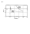
- FIG. 5 is a graph showing the current value at the time of painting and the current value at the time of non-painting in the confirmation experiment that became the beginning of the abnormal approach detection method of the electrostatic painting gun according to the present invention.
- a specific electrostatic coating gun 53 and the object to be coated 1 face each other, and the applied voltage of the electrostatic coating gun 53 is set to, for example, ⁇ 75 kV, which is the safety standard.
- the non-painting time (first current value) shown in FIG. 5 is a current value when no paint is supplied to the bell cup 53B. At the time of non-painting (first current value), the current value increases from 70 ⁇ A to 95 ⁇ A when the gun distance approaches from 200 mm to 150 mm. Is set to an abnormality detection threshold for detecting an abnormal approach of the electrostatic coating gun 53.
- the electrostatic coating gun 53 is applied to the object 1 from a gun distance of 200 mm while continuously supplying the paint to the bell cup 53B by the metering pump 53G using the same apparatus shown in FIG.
- the gun distance L was around 60 mm
- the value of the current flowing through the voltage applying device 53M is gradually increased to 80 ⁇ A, and the dielectric breakdown of the corona discharge field did not occur.
- the gun distance was 50 to 60 mm
- the current value immediately before the spark was a value (around 80 ⁇ A) that did not reach the above-described abnormality detection threshold value of 95 ⁇ A for detecting the abnormal approach.
- the occurrence of a spark due to an abnormal approach during painting cannot be prevented by only the behavior of the current value flowing through the voltage application device 53M during non-painting as in the prior art.
- the non-painting with the paint turned off is more likely to cause dielectric breakdown of the corona discharge field.
- the gun distance L is much less than the safety standard. This is appropriate for distances that are not separated, but when approaching further, it is not possible to determine whether or not sparking will occur only by detecting the current value even during painting.
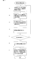
- FIG. 3 is a flowchart showing an embodiment of an abnormal approach detection method for an electrostatic coating gun according to the present invention
- FIG. 6 shows an embodiment of an abnormal approach detection method for an electrostatic coating gun according to the present invention. It is a graph which shows an example of the 1st current value (at the time of non-painting) and the 2nd current value (at the time of painting) calculated
- the current value flowing through the voltage application device 53M is carried out with the configuration of each electrostatic coating apparatus 5 to be used.
- the value of the current flowing through the voltage application device 53M when the electrostatic coating gun 53 is applied is not limited to the type of paint used, the amount of paint discharged, and the amount of shaping air.
- the current value at the time of painting is measured according to the conditions assumed to be used, such as the type of paint, the amount of paint discharged, and the flow rate of shaping air.
- the routine shown in FIG. 3 is executed for one of these conditions.
- a desired applied voltage is set, and a safe gun distance L is obtained from the above-mentioned safety standard of 4 kV / cm.
- the behavior of the current value when not painting is confirmed. That is, the above-described applied voltage is set to ⁇ 60 KV and the initial gun distance L is set to 150 mm. From this state, the electrostatic coating gun 53 is gradually brought closer to the object to be coated, and the voltage applying device 53M at each distance is set. Measure the flowing current value.
- step S2 the behavior of the current value during painting is confirmed. That is, similarly to step S1, the desired applied voltage is set to ⁇ 60 KV, the initial gun distance L is set to 150 mm, the supply of paint from this state is started, and the electrostatic coating gun 53 is gradually brought closer to the object to be coated while step S1 is started.
- the value of the current flowing through the voltage applying device 53M at each position measured in (1) is measured.
- the curve at the time of painting (second current value) shown in FIG. 6 shows the result.
- first current value second current value
- the second current value increases rapidly compared to the first current value when the supply of the paint starts from the position of the initial gun distance of 150 mm. To do. However, as the electrostatic coating gun 53 approaches the object to be coated, the increase amount of the second current value decreases compared to the increase amount of the first current value, and gradually increases. On the other hand, the first current value at the time of coating increases from the initial gun distance of 150 mm, but the increase amount at the initial stage is smaller than the increase amount of the second current value, and as it approaches the object to be coated. Increase amount becomes large.
- the first current value and the second current value are equal to each other at the illustrated intersection point P (gun distance L is about 120 mm).
- step S3 a current value and a gun distance L when the first current value and the second current value are equal (that is, both curves intersect) are obtained.
- the current value at the intersection P is 55 ⁇ A
- the gun distance L is 120 mm.
- step S4 the current value 55 ⁇ A (or a current value lower than this) at the intersection P obtained in step S3 is set as an abnormality detection threshold for detecting an abnormal approach of the electrostatic coating gun 53.
- step S5 the approach speed of the electrostatic coating gun 53 is changed and the above steps S1 to S4 are performed. In general, it is said that the current value flowing through the voltage application device 53M increases as the approach speed increases, and this is verified by the electrostatic coating gun 53.
- the abnormality detection threshold is set for all possible approach speeds, the minimum current value is set as the final abnormality detection threshold in step S6.
- the paint is turned ON between the gun distance 150 mm, which is the safety standard, and this 120 mm. Even when the paint is applied or when the paint is turned off, the current value is such that no dielectric breakdown occurs in the corona discharge field, so 55 ⁇ A is set as the abnormality detection threshold. Then, the value of the current flowing through the voltage application device 53M is monitored, and if it is less than 55 ⁇ A, it can be determined that the electrostatic coating gun 53 has not abnormally approached.
- a safety measure is taken such as whether to stop the voltage application by the voltage application device 53M or to stop the supply of the paint.
- the type of paint used, the amount of paint discharged, and the flow rate of shaping air are changed as described above, and the same steps S1 to S6 are executed and used.
- An abnormality detection threshold value is determined for each paint type, paint discharge amount, and shaping air flow rate.
- the painting robot 52 is actually operated using the determined abnormality detection threshold value, and it is verified whether or not an abnormal approach is detected.
- the abnormal approach of the electrostatic coating gun 53 can be detected regardless of whether painting or not. It is possible to prevent the occurrence of sparks.
- the gun distance L between the electrostatic coating gun 53 and the object to be coated can be shortened from 150 mm, which is said to be a safety standard. That is, even if the applied voltage is set to ⁇ 60 kV and the gun distance L is set to 130 mm, for example, there is no possibility that dielectric breakdown of the corona discharge field will occur in both coating and non-painting. If the applied voltage is set to -60 kV and the gun distance L is set to 130 mm, in order to make the pattern width equal to the pattern width when the gun distance L is 150 mm, the amount corresponding to the reduction of the gun distance L is used. Since the flow rate of the shaping air is decreased, the peeling air flow of the coating grains generated on the surface of the object is also decreased. Therefore, the coating efficiency of the paint is improved.
- the voltage application device 53M corresponds to a voltage application circuit and voltage application control means according to the present invention
- the painting robot 52 corresponds to a movement mechanism according to the present invention
- the robot control device 54 corresponds to a movement control means according to the present invention. It corresponds to.
Landscapes
- Physics & Mathematics (AREA)
- General Physics & Mathematics (AREA)
- Engineering & Computer Science (AREA)
- Robotics (AREA)
- Application Of Or Painting With Fluid Materials (AREA)
- Electrostatic Spraying Apparatus (AREA)
Abstract
静電塗装ガン(53)に印加する所望の印加電圧値と、静電塗装ガンに関する安全基準となる印加電圧値に対するガン距離の関係とから、初期のガン距離(L)を求める第1ステップと、静電塗装ガンと前記被塗物(1)とのガン距離を初期のガン距離に設定し、静電塗装ガンに塗料を供給しない状態で、所定の速度でガン距離を短くしながら静電塗装ガンの電圧印加回路に流れる第1電流値を測定する第2ステップと、静電塗装ガンと被塗物とのガン距離を初期のガン距離に設定し、静電塗装ガンへの塗料の供給を開始し、所定の速度でガン距離を短くしながら静電塗装ガンの電圧印加回路に流れる第2電流値を測定する第3ステップと、測定された第1電流値と測定された第2電流値とが等しくなる場合の電流値を求める第4ステップと、第4ステップで求められた電流値以下の値を異常検出閾値に設定する第5ステップと、を備える。
Description
本発明は、静電塗装ガンの異常接近検出方法、並びにこれを用いた静電塗装方法及び静電塗装装置に関するものである。
静電塗装において、被塗物と塗装ガンとの間に形成されたコロナ放電界が絶縁破壊してスパークが発生するのを防止するものとして、静電塗装ガンの電圧印加回路に流れる実電流値又は実電流変化量を測定し、これらが所定の上限閾値に達したら、電圧の印加を中断するものが知られている(特許文献1)。
電圧印加回路に流れる電流値は、塗装ガンに塗料を供給している状態(以下、塗装時ともいう)よりも、塗装ガンに塗料を供給していない状態(以下、非塗装時ともいう)の方が大きいといわれている。このため、上記従来技術の所定の上限閾値は、大電流が流れる可能性の高い非塗装時における実電流を基準にして定められる。しかしながら、塗装時において、高電圧印加回路に流れる電流値が、こうして定められた上限閾値に達しなければ、塗装ガンが被塗物に異常接近してもこれを検知することができないという問題がある。
本発明が解決しようとする課題は、塗装時及び非塗装時に拘わらず塗装ガンと被塗物との異常接近を検出し、これらの間に生じるスパークを防止できる静電塗装ガンの異常接近検出方法、静電塗装方法及び静電塗装装置を提供することである。
本発明は、非塗装時に電圧印加回路に流れる第1電流値と、塗装時に電圧印加回路に流れる第2電流値とが等しくなる場合の電流値以下の電流値を異常検出閾値に設定することによって上記課題を解決する。
本発明によれば、静電塗装ガンが被塗物に向かって動作しながら塗装時と非塗装時が繰り返されるが、静電塗装ガンと被塗物との間にスパークが生じない電流上限値(異常検出閾値)として、非塗装時の第1電流値と塗装時の第2電流値とが等しくなる電流値以下の電流値を設定するので、塗装時及び非塗装時に拘わらず静電塗装ガンと被塗物との異常接近を検出し、これらの間に生じるスパークを防止することができる。
以下、本発明の静電塗装ガンの異常接近検出方法と、これを用いた静電塗装装置及び静電塗装方法の一実施の形態を図面に基づいて説明する。本発明に係る静電塗装ガンの異常接近検出方法と、これを用いた静電塗装装置及び静電塗装方法は、被塗物との間に電圧を印加してコロナ放電界を形成し、当該電界中に塗料を噴霧することで塗料粒子を帯電させ、被塗物との間にクーロン力による引力を発生させて塗料の塗着効率を高める、いわゆる静電塗装方法を適用するものであれば、静電塗装ガンの方式、塗料の種類、被塗物の種類及び塗装条件等々に何ら限定されない。以下の一実施の形態は、これら本発明に係る静電塗装ガンの異常接近検出方法と、これを用いた静電塗装装置及び静電塗装方法を、自動車ボディを塗装ブース内で塗装する場合に適用したものであり、図1は、本発明に係る静電塗装装置を自動車ボディの塗装ブースに適用した一実施の形態を示す半正面図である。
本実施形態では、被塗物としての自動車ボディ1が、塗装台車2に搭載された状態で、塗装ブース3内をフロアコンベア4により定速度で搬送される。この間に、塗装ブース3の両サイドに設置された塗装ロボット52は、予め教示された塗装軌跡PL(図1に点線で示す)に沿って移動し、その間に静電塗装ガン53から自動車ボディ1の外板に向かって塗料が塗布される。そのため、本実施形態の静電塗装装置5は、静電塗装ガン53と、この静電塗装ガン53をハンドに装着し、予め教示された塗装軌跡にしたがって静電塗装ガン53を移動させる塗装ロボット52と、静電塗装ガン53及び塗装ロボット52を制御する制御装置51と、を備える。
ちなみに、塗装ブース3は、自動車ボディ1の塗装工程であれば、中塗り塗装ブース又は上塗り塗装ブースのいずれでもよく、自動車部品の塗装工程であれば、下塗り塗装ブース(プライマ塗装ブース)、中塗り塗装ブース又は上塗り塗装ブースのいずれでもよい。また、被塗物の搬送形態は、被塗物が自動車ボディ1であれば当該自動車ボディ1を搭載した塗装台車2をフロアコンベア4で牽引することが一般的であるが、被塗物が自動車部品(バンパその他の樹脂製部品など)である場合は、自動車部品の形状に応じた搭載治具をフロアコンベア又はオーバーヘッドコンベアで牽引すればよい。さらに、被塗物の搬送形態は、一定のピッチで複数の被塗物を定速度で連続的に搬送してもよいし、いわゆるバッチ搬送方式で一又は複数の被塗物を搬送し、被塗物が停止した状態で塗装してもよい。
塗装ロボット52は、図1に示すように塗装ブース3の両サイドに設置され、塗装ブース3の延在方向に沿って必要な台数だけ間隔をあけて設置されている。たとえば自動車ボディ1の上塗り塗装工程では、上塗りベース塗装と上塗りクリヤ塗装とがウェットオンウェットで行われるので、上塗りベース塗装用としての塗装ロボット52と、上塗りクリヤ塗装用としての塗装ロボット52がそれぞれ必要台数だけ設置される。またたとえば自動車ボディ1の中塗り塗装工程では、一般中塗り塗装と内板塗装とがウェットオンウェットで行われるので、一般中塗り塗装用としての塗装ロボット52と、内板塗装用としての塗装ロボット52がそれぞれ必要台数だけ設置される。なお、塗装ロボット52の設置台数は特に限定されないが、その塗装ブース3、延いては塗装工程全体の生産能力(単位時間当たりの生産台数)と、塗装ロボット52の作業能力(単位時間当たりの塗布面積)等に応じて設定され、塗装工程全体の生産能力が高いほど、また塗装ロボット52の作業能力が低いほど相対的に多くの塗装ロボット52が設置される。
塗装ロボット52は、たとえば多関節ロボットであって、ハンドに静電塗装ガン53が装着されている。また、塗装ロボット52は、予め設定された一又は複数の塗装軌跡PLを教示操作によって記憶させるロボット制御装置54を備え、このロボット制御装置54は、車種検出器6により検出された塗装仕様(自動車ボディ1の車型、塗装色など)に応じた塗装軌跡PLを抽出し、図示しない塗装台車2の検出器によりその自動車ボディ1が所定位置に到着したことを検出したら、抽出された塗装軌跡に沿って静電塗装ガン53を移動させる。そして、所定の移動が終了したら原位置に移動して次の自動車ボディ1が到着するのを待機する。塗装ロボット52は、自動車ボディ1の搬送方向に同期して移動する移動機構を備えてもよい。
ちなみに、本発明の静電塗装ガンの異常接近検出方法と、これを用いた静電塗装装置及び静電塗装方法においては、本実施形態で示す、塗装軌跡PLが自由に設定できる塗装ロボット52以外にも、予め定められた所定の塗装軌跡PLに沿って静電塗装ガン53を移動させるレシプロ式自動機を用いることもできる。
本実施形態の静電塗装ガン53は、静電塗装を行う塗装ガンであれば特に限定されず、回転霧化式静電塗装ガン又はエア霧化式静電塗装ガンのいずれも用いることができる。また回転霧化式静電塗装ガンにおいては、塗料が供給されて回転するベルカップの周囲に針状のグリッド電極を設け、このグリッド電極に電圧を印加することでコロナ放電界を形成する間接印加方式の回転霧化式静電塗装ガンであってもよいし、ベルカップを含めた静電塗装ガン自体に電圧を印加することでコロナ放電界を形成する直接印加式の回転霧化式静電塗装ガンであってもよい。特に塗料として水系塗料のような導電性塗料を用いる場合は、間接印加方式の回転霧化式静電塗装ガンを用いることが多いが、直接印加方式の回転霧化式静電塗装ガンであってもボルテージブロック機構(静電塗装ガンを塗料供給系の途中で電気的に絶縁する機構)を設ければ導電性塗料を用いることができる。本実施形態では、一般的な直接印加方式の回転霧化式静電塗装ガンを用いたもので本発明を説明するものとする。
図2は、本実施形態の直接印加方式の回転霧化式静電塗装ガン53を示すブロック図であり、本図では機械的な構成は概略化し、主として機能的な構成を示す。本実施形態の静電塗装ガン53は、電気絶縁性材料により形成されたガン筐体53Aと、当該ガン筐体53Aに回転自在に装着された中空シャフト(不図示)と、当該中空シャフトの先端に装着されたベルカップ53Bと、中空シャフト及びベルカップ53Bを回転させるエアモータ53Cと、ベルカップ53Bに塗料を供給する塗料供給系統53Eと、ベルカップ53Bに電圧を印加する電圧印加装置53Mと、ベルカップ53Bの周囲にシェーピングエアを供給するエア供給系統53Pと、を備える。
ベルカップ53Bは、略カップ形状とされ、金属などの導電性材料から形成され、ベルカップ53Bの内面の中心に、中空シャフトに挿通されたフィードチューブ53Fからの塗料が供給される。そして、ベルカップ53Bの中心に供給された塗料は、ベルカップ53Bの回転による遠心力によりベルカップ53Bの内面を外周縁に向かって薄く引き伸ばされながら拡散し、外周縁から霧状に微粒化されて放出する。エアモータ53Cには、圧縮空気を生成するコンプレッサ53Tからの圧縮エアが供給されるが、エアモータ53CのON/OFF及び回転速度の制御は、当該エアモータ制御装置53Dにより実行される。
塗料供給系統53Eは、上述した中空シャフトに挿通されたフィードチューブ53Fに塗料を圧送する定量ポンプ53G(ギヤポンプなど)と、上塗り塗装などにおいて塗料種を切り換えるためのカラーチェンジバルブ53Hが塗料配管53Jに設けられた構成とされ、当該塗料配管53Jの基端は、一又は複数の塗料タンク53Kに接続されている。なお、カラーチェンジバルブ53Hには、色替え時にフィードチューブ53F内に残留した塗料を押し出して洗浄するためのエアと洗浄剤(有機溶剤系塗料にあっては洗浄用シンナー、水系塗料にあっては水)とを供給する配管も接続されている。なお、定量ポンプ53Gによる塗料の吐出量の制御と、カラーチェンジバルブ53Hの切り替え制御は、塗料供給系統制御装置53Lからの制御信号により実行される。また、カラーチェンジバルブ53Hによる色替え操作は、現在の自動車のディの塗装終了後であって次の自動車ボディ1が到着するまでの待機時間内において実行される。塗料供給系統制御装置53Lは、車種検出器6からの車種信号を受信し、予め記憶されている塗料の吐出量や塗色の情報を定量ポンプ53Gとカラーチェンジバルブ53Hに出力する。また、詳細は後述するが、静電塗装ガン53が被塗物に異常接近した場合には、スパークの発生を防止するために、フィードチューブ53Fの先端などに設けられた開閉バルブ(不図示)を閉塞するとともに定量ポンプ53Gによる塗料の供給を中止する。
電圧印加装置53Mは、ガン筐体53A内に収納され、少なくともベルカップ53Bに所望の高電圧が印加されるように電気的に接続されている。一般に自動車ボディ1の塗装工程では、静電塗装ガン53に-30~-90KVの高電圧が印加されるが、特に限定はされない。電圧印加装置53Mは、電圧制御装置53Nにより、その印加電圧とON/OFFが制御される。また、詳細は後述するが、静電塗装ガン53が被塗物に異常接近した場合には、スパークの発生を防止するために電圧印加装置53Mによる電圧印加が遮断される。
シェーピングエアを供給するエア供給系統53Pは、コンプレッサ53Tに接続されたエア配管53Qと、当該エア配管53Qに設けられシェーピングエア圧を制御する制御バルブ53Rと、制御バルブ53Rの開閉を制御するエア供給系統制御装置53Sとを備える。シェーピングエア圧を高くすれば、ベルカップ53Bの外周縁から放出されるメガホン状の塗粒のパターン幅が小さくなり、単位面積当たりの塗着膜厚が厚くなるが、塗着効率は低下する傾向にある。逆に、シェーピングエア圧を低くすれば、ベルカップ53Bの外周縁から放出されるメガホン状の塗粒のパターン幅が大きくなり、単位面積当たりの塗着膜厚が薄くなるが、塗着効率は増加する傾向にある。こうしたシェーピング圧は、塗装ロボット52による塗装軌跡PLとの関係等で定められる。
ところで、こうした静電塗装を行う場合には、静電塗装ガン53と被塗物である自動車ボディ1(以下、被塗物1ともいう。)との距離(以下、ガン距離Lともいう)が近いほど、また静電塗装ガン53に印加する電圧が高いほど、ベルカップ53Bから放出された塗粒の飛散が抑制され、塗着効率(ベルカップ53Bから放出された塗料重量に対する被塗物に塗着した塗料重量の割合)が高い。しかしながら、静電塗装ガン53と被塗物との間に形成されるコロナ放電界が絶縁破壊すると、静電塗装ガン53と被塗物との間に瞬間的なスパークが発生し、塗装ブース3の防火の観点から好ましくない。そのため、静電塗装においては、印加電圧値に対する安全なガン距離というものが定められており、一般に、図4(静電塗装ガン53に関する安全基準となる印加電圧値に対するガン距離の関係を示すグラフ)に示すように、絶対値でたとえば4kV/cm以下にすることが安全基準とされている。たとえば、-30kVの印加電圧を設定する場合は、ガン距離Lを30/4=75mm以上、-60kVの印加電圧を設定する場合は、ガン距離Lを60/4=150mm以上、-90kVの印加電圧を設定する場合は、ガン距離Lを90/4=225mm以上にそれぞれ設定することが防火の観点から好ましいとされている。
また、自動車ボディ1などのように単純でない形状の被塗物を静電塗装する場合には、塗装軌跡PLの途中で塗料のON/OFFを繰り返しながら塗装することが多いが、塗料をONした塗装時に比べて、塗料をOFFした非塗装時の方が、電圧印加装置53Mに流れる電流値が大きくなり、コロナ放電界の絶縁破壊が生じる可能性が高くなるといわれている。ベルカップ53Bから放出された塗粒がコロナ放電界の電気抵抗となると考えられるからである。そのため、全ての塗装軌跡PLにおいて塗料をOFF(非塗装時)した状態で電圧印加装置53Mに流れる電流値を予め測定し、スパークが発生しない最大電流値を、静電塗装ガン53の異常接近を検出する上限閾値に設定することが従来行われていた。
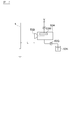
図5は、本発明に係る静電塗装ガンの異常接近検出方法の端緒となった確認実験における塗装時の電流値及び非塗装時の電流値を示すグラフである。この確認実験では、図7に示すように、特定の静電塗装ガン53と被塗物1とを対面させ、静電塗装ガン53の印加電圧をたとえば-75kVに設定し、上記安全基準である4kV/cmから算出される安全なガン距離Lを200mmに設定する。そして、このガン距離L=200mmの位置から所定速度で静電塗装ガン53を被塗物1に近づけていった場合に、電圧印加装置53Mに流れる電流値を測定したものである。図5に示す非塗装時(第1電流値)は、ベルカップ53Bに塗料を供給しない非塗装時における電流値である。この非塗装時(第1電流値)では、ガン距離200mmから150mmに近づくと電流値が70μAから95μAまで増加することから、これ以上の電流が流れるとスパークの発生が懸念されるので、この95μAを静電塗装ガン53の異常接近を検出するための異常検出閾値に設定することとした。
しかしながら、本発明者らが検証したところ、図7に示す同じ機器を用いて、定量ポンプ53Gによりベルカップ53Bに塗料を供給し続けながらガン距離200mmから静電塗装ガン53を被塗物1に近づけていくと、ガン距離Lが60mm前後までは、電圧印加装置53Mに流れる電流値も80μAまで徐々に増加する程度であり、コロナ放電界の絶縁破壊は生じなかったが、それより近づいたときに(ガン距離が50~60mm)、突如絶縁破壊が生じ、スパークが発生した。しかも、スパーク直前の電流値は、上述した異常接近を検出する異常検出閾値である95μAに達していない値(80μA前後)であった。したがって、従来のように非塗装時における電圧印加装置53Mに流れる電流値の挙動だけでは、塗装時の異常接近によるスパークの発生は未然に防止できないことになる。従来言われてきた、塗料をONした塗装時に比べて塗料をOFFした非塗装時の方が、コロナ放電界の絶縁破壊が生じる可能性が高くなるということは、ガン距離Lが安全基準からさほど離れていない距離の場合は妥当するが、それ以上接近すると、塗装時においても電流値の検出だけではスパークが生じるか否かを判定できないことになる。
そこで本発明者らは、塗装時であっても非塗装時であっても、電圧印加装置53Mに流れる電流値を検出するだけでコロナ放電界の絶縁破壊が生じることなく、静電塗装ガン53の異常接近を検出し、未然にスパークの発生を防止できる方法を完成するに至った。以下、本発明に係る静電塗装ガンの異常接近検出方法の一実施の形態を説明する。図3は、本発明に係る静電塗装ガンの異常接近検出方法の一実施の形態を示すフローチャート、図6は、本発明に係る静電塗装ガンの異常接近検出方法の一実施の形態にて求められる第1電流値(非塗装時)及び第2電流値(塗装時)の一例を示すグラフである。
静電塗装ガン53の非塗装時に発生するコロナ放電の発生量は、静電塗装ガン53の機種、ベルカップ53Bの形状、印加電圧値等の条件で異なるため、電圧印加装置53Mに流れる電流値の測定は、使用する静電塗装装置5ごとの構成にて実施する。また、静電塗装ガン53の塗装時に電圧印加装置53Mに流れる電流値は、上記の静電塗装装置5の機器構成の影響の他に、使用する塗料の種類、塗料の吐出量、シェーピングエアの流量等の影響を受けるため、塗装時の電流値の測定は、塗料の種類、塗料の吐出量、シェーピングエアの流量等を使用が想定される条件と合わせて実施する。図3に示すルーチンは、こうした各条件のうちの一つの条件について実行するものである。
上記の前提条件のもと、まず所望の印加電圧を設定し、上述した安全基準である4kV/cmから安全なガン距離Lを求める。図6に示す例では、所望の印加電圧を-60KVとした場合であり、安全基準である4kV/cmから、60/4=150mmを初期のガン距離Lに設定した。そして、図3のステップS1では、非塗装時の電流値の挙動を確認する。すなわち、上述した印加電圧を-60KVに設定するとともに初期のガン距離Lを150mmに設定し、この状態から静電塗装ガン53を徐々に被塗物に近づけつつ、各距離における電圧印加装置53Mに流れる電流値を測定する。図6に示す非塗装時(第1電流値)の曲線がその結果を示す。
次のステップS2では、塗装時の電流値の挙動を確認する。すなわち、ステップS1と同様に、所望の印加電圧を-60KV、初期のガン距離Lを150mmとし、この状態から塗料を供給し始めて静電塗装ガン53を徐々に被塗物に近づけつつ、ステップS1で測定した各位置における電圧印加装置53Mに流れる電流値を測定する。図6に示す塗装時(第2電流値)の曲線がその結果を示す。ここで、初期のガン距離Lである150mmにおける第2電流値は、塗料を供給していない被塗装時の電流値を測定している(そのため、第1電流値=第2電流値)。そして、定量の塗料を供給し始めるのと同時に静電塗装ガン53を徐々に被塗物に近づける。
図6の第1電流値及び第2電流値の曲線に示すように、第2電流値は、初期のガン距離150mmの位置から塗料の供給が開始すると、第1電流値に比べて急激に増加する。しかしながら、静電塗装ガン53が被塗物に近づくにつれ第2電流値の増加量は第1電流値の増加量に比べて減少し、漸増状態となる。これに対して、被塗装時の第1電流値は、初期のガン距離150mmから増加はするものの、初期段階の増加量は第2電流値の増加量に比べて小さく、被塗物に近づくにつれて増加量が大きくなる。そして、図示する交点P(ガン距離Lが約120mm)において第1電流値と第2電流値が等しい電流値となる。ステップS3においては、この第1電流値と第2電流値とが等しくなる(すなわち両曲線が交わる)ときの電流値とガン距離Lを求める。図示する例では交点Pにおける電流値は55μA、ガン距離Lは120mmである。
次のステップS4では、静電塗装ガン53の異常接近を検出するための異常検出閾値として、上記ステップS3で求めた交点Pの電流値55μA(又はこれ以下の電流値でもよい)を設定する。そして、ステップS5では、静電塗装ガン53の接近速度を変えて以上のステップS1~S4を実施する。一般に接近速度が大きいほど電圧印加装置53Mに流れる電流値は大きくなるといわれているが、これをその静電塗装ガン53にて検証する。可能性のある接近速度の全てについて異常検出閾値が設定されたら、ステップS6において、そのうちの最小の電流値を最終的な異常検出閾値に設定する。たとえば、図示する例において最終的な異常検出閾値が55μA、そのときのガン距離Lが120mmであったとすると、安全基準とされるガン距離150mmから、この120mmまでの間については、塗料がONされている塗装時であっても、塗料がOFFされている非塗装時であっても、コロナ放電界に絶縁破壊が生じない電流値となるから、異常検出閾値として55μAを設定する。そして、電圧印加装置53Mに流れる電流値を監視して、当該55μA未満であれば静電塗装ガン53の異常接近は生じていないと判断できる。逆に、電圧印加装置53Mに流れる電流値を監視して当該55μA以上となれば、塗装時及び非塗装時において静電塗装ガン53の異常接近の可能性があり、スパークが発生するおそれがあるので、電圧印加装置53Mによる電圧印加を中止するか、塗料の供給を停止するかといった安全策を採る。
なお、ステップS1~S6により異常検出閾値が決定したら、上述したように使用する塗料の種類、塗料の吐出量、シェーピングエアの流量を変更し、同様のステップS1~S6を実行し、これら使用する塗料の種類、塗料の吐出量、シェーピングエアの流量ごとに異常検出閾値を決定する。そして、ステップS7においては、決定された異常検出閾値を用いて実際に塗装ロボット52を動作させ、異常接近が検出されるか否かを検証する。
以上の手順により、図6に示す所望の印加電圧が-60kV、ガン距離Lが150mmの場合(特定の塗料の種類、塗料の吐出量、シェーピングエアの流量である)は、交点Pの電流値が55μA,ガン距離Lが120mmとなり、異常検出閾値を55μAに設定して電圧印加装置53Mに流れる電流値を監視すれば、塗装時及び非塗装時に拘らず静電塗装ガン53の異常接近を検出することができ、スパークの発生を未然に防止することができる。
また見方を変えれば、静電塗装ガン53と被塗物とのガン距離Lは、安全基準といわれている150mmより短縮できるという意味でもある。すなわち、印加電圧を-60kVに設定し、たとえばガン距離Lを130mmにしても、塗装時及び非塗装時のいずれにおいてもコロナ放電界の絶縁破壊が生じるおそれはない。そして仮に印加電圧を-60kV、ガン距離Lを130mmにした場合には、パターン幅を、ガン距離Lが150mmの場合のパターン幅と同等にするためには、ガン距離Lが短縮された分だけシェーピングエアの流量を減少させるから、被塗物表面に生じる塗粒の剥離気流も減少する。したがって、塗料の塗着効率が向上する。
上記電圧印加装置53Mは本発明に係る電圧印加回路及び電圧印加制御手段に相当し、上記塗装ロボット52は本発明に係る移動機構に相当し、上記ロボット制御装置54は本発明に係る移動制御手段に相当する。
1…自動車ボディ
2…塗装台車
3…塗装ブース
4…フロアコンベア
5…静電塗装装置
51…制御装置
52…塗装ロボット
54…ロボット制御装置
53…静電塗装ガン
53A…ガン筐体
53B…ベルカップ
53C…エアモータ
53U…制御バルブ
53D…エアモータ制御装置
53E…塗料供給系統
53F…フィードチューブ
53G…定量ポンプ
53H…カラーチェンジバルブ
53J…塗料配管
53K…塗料タンク
53L…塗料供給系統制御装置
53M…電圧印加装置
53N…電圧制御装置
53P…エア供給系統
53Q…エア配管
53R…制御バルブ
53S…エア供給系統制御装置
53T…コンプレッサ
6…車種検出器
L…ガン距離
PL…塗装軌跡
2…塗装台車
3…塗装ブース
4…フロアコンベア
5…静電塗装装置
51…制御装置
52…塗装ロボット
54…ロボット制御装置
53…静電塗装ガン
53A…ガン筐体
53B…ベルカップ
53C…エアモータ
53U…制御バルブ
53D…エアモータ制御装置
53E…塗料供給系統
53F…フィードチューブ
53G…定量ポンプ
53H…カラーチェンジバルブ
53J…塗料配管
53K…塗料タンク
53L…塗料供給系統制御装置
53M…電圧印加装置
53N…電圧制御装置
53P…エア供給系統
53Q…エア配管
53R…制御バルブ
53S…エア供給系統制御装置
53T…コンプレッサ
6…車種検出器
L…ガン距離
PL…塗装軌跡
Claims (14)
- 静電塗装ガンと被塗物との異常接近を検出する方法において、
前記静電塗装ガンに印加する所望の印加電圧値と、静電塗装ガンに関する安全基準となる印加電圧値に対するガン距離の関係とから、初期のガン距離を求める第1ステップと、
前記静電塗装ガンと前記被塗物とのガン距離を前記初期のガン距離に設定し、前記静電塗装ガンに塗料を供給しない状態で、所定の速度で前記ガン距離を短くしながら前記静電塗装ガンの電圧印加回路に流れる第1電流値を測定する第2ステップと、
前記静電塗装ガンと前記被塗物とのガン距離を前記初期のガン距離に設定し、前記静電塗装ガンへの塗料の供給を開始し、前記所定の速度で前記ガン距離を短くしながら前記静電塗装ガンの電圧印加回路に流れる第2電流値を測定する第3ステップと、
前記測定された第1電流値と前記測定された第2電流値とが等しくなる場合の電流値を求める第4ステップと、
前記第4ステップで求められた電流値以下の値を異常検出閾値に設定する第5ステップと、を備える静電塗装ガンの異常接近検出方法。 - 前記測定された第1電流値と前記測定された第2電流値とが等しくなる場合のガン距離を求める第6ステップと、
前記所望の印加電圧値を前記静電塗装ガンに印加する電圧値の上限値に設定し、前記第6ステップで求められたガン距離を前記静電塗装ガンと前記被塗物とのガン距離の最小値に設定する第7ステップと、を備える請求項1に記載の静電塗装ガンの異常接近検出方法。 - 前記静電塗装ガンに流れる電流値が前記異常検出閾値を超えた場合に、前記静電塗装ガンへの電圧印加を停止及び/又は塗料の供給を停止する第8ステップを備える請求項1又は2に記載の静電塗装ガンの異常接近検出方法。
- 前記静電塗装ガンの機種、ベルカップの形状、塗料の種類、塗料の吐出量及びシェーピングエアの流量のうち少なくとも一つの属性毎に前記異常検出閾値を設定する請求項1~3のいずれか一項に記載の静電塗装ガンの異常接近検出方法。
- 前記所定の速度を複数設定し、各所定の速度について前記第4ステップで求められた電流値のうちの最小値を、前記第5ステップにおける異常検出閾値の最大値とする請求項1~4のいずれか一項に記載の静電塗装ガンの異常接近検出方法。
- 静電塗装ガンに所定の電圧を印加し被塗物に塗料を塗布する静電塗装方法において、
予め前記被塗物に塗料を塗布する前に、
前記所定の印加電圧値と、静電塗装ガンに関する安全基準となる印加電圧値に対するガン距離の関係とから、初期のガン距離を求め、
前記静電塗装ガンと前記被塗物とのガン距離を前記初期のガン距離に設定し、前記静電塗装ガンに塗料を供給しない状態で、所定の速度で前記ガン距離を短くしながら前記静電塗装ガンの電圧印加回路に流れる第1電流値を測定し、
前記静電塗装ガンと前記被塗物とのガン距離を前記初期のガン距離に設定し、前記静電塗装ガンへの塗料の供給を開始し、前記所定の速度で前記ガン距離を短くしながら前記静電塗装ガンの電圧印加回路に流れる第2電流値を測定し、
前記測定された第1電流値と前記測定された第2電流値とが等しくなる場合の電流値及びその場合のガン距離を求め、
前記第1電流値と前記第2電流値とが等しくなる電流値以下の値を異常検出閾値に設定し、
その後、
前記所定の印加電圧値を前記静電塗装ガンに印加する電圧値の上限値に設定し、前記第1電流値と前記第2電流値とが等しくなる場合のガン距離を前記静電塗装ガンと前記被塗物とのガン距離の最小値に設定し、被塗物に塗料を塗布する静電塗装方法。 - 前記静電塗装ガンに流れる電流値が前記異常検出閾値を超えた場合に、前記静電塗装ガンへの電圧の印加を停止及び/又は塗料の供給を停止する請求項6に記載の静電塗装方法。
- 前記静電塗装ガンの機種、ベルカップの形状、塗料の種類、塗料の吐出量及びシェーピングエアの流量のうち少なくとも一つの属性毎に、前記異常検出閾値、前記静電塗装ガンに印加する電圧値の上限値及び前記前記静電塗装ガンと前記被塗物とのガン距離の最小値を設定する請求項6又は7に記載の静電塗装方法。
- 前記所定の速度を複数設定し、各所定の速度について前記第1電流値と前記第2電流値とが等しくなる電流値のうちの最小値を、前記異常検出閾値の最大値とする請求項6~8のいずれか一項に記載の静電塗装方法。
- 被塗物に対して塗料を塗布する静電塗装ガンと、
前記静電塗装ガンを所定の塗装軌跡に沿って移動させる移動機構と、
前記静電塗装ガンと前記被塗物とのガン距離が設定され、前記移動機構を制御する移動制御手段と、
印加電圧値と異常検出閾値が設定され、前記静電塗装ガンに印加する電圧を制御する電圧印加制御手段と、を備える静電塗装装置において、
予め前記被塗物に塗料を塗布する前に、
前記静電塗装ガンに印加する所望の印加電圧値と、静電塗装ガンに関する安全基準となる印加電圧値に対するガン距離の関係とから、初期のガン距離を求め、
前記静電塗装ガンと前記被塗物とのガン距離を前記初期のガン距離に設定し、前記静電塗装ガンに塗料を供給しない状態で、所定の速度で前記ガン距離を短くしながら前記静電塗装ガンの電圧印加回路に流れる第1電流値を測定し、
前記静電塗装ガンと前記被塗物とのガン距離を前記初期のガン距離に設定し、前記静電塗装ガンへの塗料の供給を開始し、前記所定の速度で前記ガン距離を短くしながら前記静電塗装ガンの電圧印加回路に流れる第2電流値を測定し、
前記測定された第1電流値と前記測定された第2電流値とが等しくなる場合の電流値及びその場合のガン距離を求め、
前記第1電流値と前記第2電流値とが等しくなる電流値以下の値を、前記電圧印加制御手段の前記異常検出閾値に設定し、
前記所望の印加電圧値を、前記電圧印加制御手段の前記印加電圧値の上限値に設定し、
前記第1電流値と前記第2電流値とが等しくなる場合のガン距離を、前記移動制御手段の前記ガン距離の最小値に設定する静電塗装装置。 - 前記電圧印加制御手段は、前記静電塗装ガンに流れる電流値が前記異常検出閾値を超えた場合に、前記静電塗装ガンへの電圧印加を停止する請求項10に記載の静電塗装装置。
- 前記静電塗装ガンに塗料を供給する塗料供給手段をさらに備え、
前記塗料供給手段は、前記静電塗装ガンに流れる電流値が前記異常検出閾値を超えた場合に、前記静電塗装ガンへの塗料の供給を停止する請求項10又は11に記載の静電塗装装置。 - 前記静電塗装ガンの機種、ベルカップの形状、塗料の種類、塗料の吐出量及びシェーピングエアの流量のうち少なくとも一つの属性毎に、前記異常検出閾値、前記静電塗装ガンに印加する電圧値の上限値及び前記前記静電塗装ガンと前記被塗物とのガン距離の最小値を設定する請求項10~12のいずれか一項に記載の静電塗装装置。
- 前記所定の速度を複数設定し、各所定の速度について前記第1電流値と前記第2電流値とが等しくなる電流値のうちの最小値を、前記異常検出閾値の最大値とする請求項10~13のいずれか一項に記載の静電塗装装置。
Priority Applications (1)
| Application Number | Priority Date | Filing Date | Title |
|---|---|---|---|
| PCT/JP2015/064868 WO2016189610A1 (ja) | 2015-05-25 | 2015-05-25 | 静電塗装ガンの異常接近検出方法、静電塗装方法及び静電塗装装置 |
Applications Claiming Priority (1)
| Application Number | Priority Date | Filing Date | Title |
|---|---|---|---|
| PCT/JP2015/064868 WO2016189610A1 (ja) | 2015-05-25 | 2015-05-25 | 静電塗装ガンの異常接近検出方法、静電塗装方法及び静電塗装装置 |
Publications (1)
| Publication Number | Publication Date |
|---|---|
| WO2016189610A1 true WO2016189610A1 (ja) | 2016-12-01 |
Family
ID=57393828
Family Applications (1)
| Application Number | Title | Priority Date | Filing Date |
|---|---|---|---|
| PCT/JP2015/064868 Ceased WO2016189610A1 (ja) | 2015-05-25 | 2015-05-25 | 静電塗装ガンの異常接近検出方法、静電塗装方法及び静電塗装装置 |
Country Status (1)
| Country | Link |
|---|---|
| WO (1) | WO2016189610A1 (ja) |
Cited By (1)
| Publication number | Priority date | Publication date | Assignee | Title |
|---|---|---|---|---|
| CN113042288A (zh) * | 2021-03-22 | 2021-06-29 | 深圳市德贝尔喷枪有限公司 | 一种高均匀性全自动粉末喷涂生产线及其喷涂方法 |
Citations (3)
| Publication number | Priority date | Publication date | Assignee | Title |
|---|---|---|---|---|
| JPS491987U (ja) * | 1972-04-07 | 1974-01-09 | ||
| JPS5820268A (ja) * | 1981-07-31 | 1983-02-05 | Origin Electric Co Ltd | 静電塗装方法 |
| WO2013111664A1 (ja) * | 2012-01-25 | 2013-08-01 | Abb株式会社 | 静電塗装装置 |
-
2015
- 2015-05-25 WO PCT/JP2015/064868 patent/WO2016189610A1/ja not_active Ceased
Patent Citations (3)
| Publication number | Priority date | Publication date | Assignee | Title |
|---|---|---|---|---|
| JPS491987U (ja) * | 1972-04-07 | 1974-01-09 | ||
| JPS5820268A (ja) * | 1981-07-31 | 1983-02-05 | Origin Electric Co Ltd | 静電塗装方法 |
| WO2013111664A1 (ja) * | 2012-01-25 | 2013-08-01 | Abb株式会社 | 静電塗装装置 |
Cited By (2)
| Publication number | Priority date | Publication date | Assignee | Title |
|---|---|---|---|---|
| CN113042288A (zh) * | 2021-03-22 | 2021-06-29 | 深圳市德贝尔喷枪有限公司 | 一种高均匀性全自动粉末喷涂生产线及其喷涂方法 |
| CN113042288B (zh) * | 2021-03-22 | 2022-04-22 | 深圳市德贝尔喷枪有限公司 | 一种高均匀性全自动粉末喷涂生产线及其喷涂方法 |
Similar Documents
| Publication | Publication Date | Title |
|---|---|---|
| EP1295648B1 (en) | Two-tone coating method | |
| KR101826738B1 (ko) | 스프레이건 및 이를 이용한 도장 시스템 | |
| KR101282287B1 (ko) | 도장로봇을 이용한 자동 도장 시스템 및 도료 비산 방지를 위한 도장기 | |
| CN110743719B (zh) | 静电微粒化式涂装装置以及静电微粒化式涂装方法 | |
| CN113853252A (zh) | 静电涂覆系统及方法 | |
| US9354626B2 (en) | Method for restarting a robot | |
| CN102596422B (zh) | 具有对喷雾器转速和高压进行动态匹配的涂层方法和涂层设备 | |
| EP3978362B1 (en) | Flying object, flying object system, and method for painting object to be painted | |
| CN107081228A (zh) | 一种喷涂面积自动控制的静电粉末喷涂机 | |
| CN110947534B (zh) | 涂装装置 | |
| KR20160033972A (ko) | 균일한 도막 두께 형성이 가능한 도료 분사 장치 | |
| CN105612010B (zh) | 用于给具有特征棱边的构件喷漆的喷漆方法以及喷漆设备 | |
| KR101581287B1 (ko) | 플라스틱 부품 도장장치 | |
| WO2016189610A1 (ja) | 静電塗装ガンの異常接近検出方法、静電塗装方法及び静電塗装装置 | |
| CN103826755B (zh) | 对喷流非对称性补偿的涂覆方法与涂覆装置 | |
| JP5390259B2 (ja) | 静電塗装装置及び塗装方法 | |
| JP4327846B2 (ja) | 回転霧化頭型塗装装置 | |
| JPH0459945B2 (ja) | ||
| JP3754632B2 (ja) | ツートーン塗装方法 | |
| KR20070114843A (ko) | 도막 형성장치 | |
| CN106413910A (zh) | 具有外部充电点的静电喷枪 | |
| US11969750B2 (en) | Painting method and painting apparatus for insulator | |
| JP5731218B2 (ja) | 静電塗装装置 | |
| JPH0150463B2 (ja) | ||
| KR20140117875A (ko) | 레귤레이터가 장착된 자동도장장비를 이용한 도장방법 |
Legal Events
| Date | Code | Title | Description |
|---|---|---|---|
| 121 | Ep: the epo has been informed by wipo that ep was designated in this application |
Ref document number: 15893246 Country of ref document: EP Kind code of ref document: A1 |
|
| DPE2 | Request for preliminary examination filed before expiration of 19th month from priority date (pct application filed from 20040101) | ||
| NENP | Non-entry into the national phase |
Ref country code: DE |
|
| 122 | Ep: pct application non-entry in european phase |
Ref document number: 15893246 Country of ref document: EP Kind code of ref document: A1 |
|
| NENP | Non-entry into the national phase |
Ref country code: JP |