WO2016189595A1 - 無線通信システム、無線装置および処理方法 - Google Patents
無線通信システム、無線装置および処理方法 Download PDFInfo
- Publication number
- WO2016189595A1 WO2016189595A1 PCT/JP2015/064799 JP2015064799W WO2016189595A1 WO 2016189595 A1 WO2016189595 A1 WO 2016189595A1 JP 2015064799 W JP2015064799 W JP 2015064799W WO 2016189595 A1 WO2016189595 A1 WO 2016189595A1
- Authority
- WO
- WIPO (PCT)
- Prior art keywords
- transmission
- transmission points
- received power
- base station
- terminal
- Prior art date
- Legal status (The legal status is an assumption and is not a legal conclusion. Google has not performed a legal analysis and makes no representation as to the accuracy of the status listed.)
- Ceased
Links
Images




Classifications
-
- H—ELECTRICITY
- H04—ELECTRIC COMMUNICATION TECHNIQUE
- H04W—WIRELESS COMMUNICATION NETWORKS
- H04W24/00—Supervisory, monitoring or testing arrangements
- H04W24/10—Scheduling measurement reports ; Arrangements for measurement reports
-
- H—ELECTRICITY
- H04—ELECTRIC COMMUNICATION TECHNIQUE
- H04W—WIRELESS COMMUNICATION NETWORKS
- H04W28/00—Network traffic management; Network resource management
- H04W28/16—Central resource management; Negotiation of resources or communication parameters, e.g. negotiating bandwidth or QoS [Quality of Service]
Definitions
- the present invention relates to a wireless communication system, a wireless device, and a processing method.
- a CoMP transmission / reception (Coordinated Multiple-Point transmission and reception) system (hereinafter abbreviated as CoMP) using a plurality of reception points for receiving data signals is known.
- CoMP Coordinatd Multiple-Point transmission and reception
- the wireless capacity can be increased by increasing the arrangement density of transmission points.
- each base station transmits a common pilot signal having a different pseudo-random noise offset for other base stations (see, for example, Patent Document 1 below). ).
- CSI-RS Channel State Information-Reference Signal: channel state information reference signal
- OFDM Orthogonal Frequency Division Multiplexing
- an object of the present invention is to provide a wireless communication system, a wireless device, and a processing method that can suppress an increase in the amount of wireless resources required for notification of transmission point candidate information.
- a first wireless device that transmits a data signal by coordinating each transmission point included in a plurality of transmission points includes the plurality of transmission points.
- a reference signal is transmitted from each transmission point
- the second wireless device measures the received power of the reference signal transmitted from each of the plurality of transmission points by the first wireless device, and each bit position is the plurality of transmissions.
- a radio communication system, a radio apparatus, and a process for transmitting a bit string that is associated with a point and that indicates whether or not the received power satisfies a predetermined condition for each of the plurality of transmission points to the first radio apparatus A method is proposed.
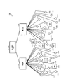
- FIG. 1 is a diagram illustrating an example of a wireless communication system according to an embodiment.
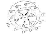
- FIG. 2 is a diagram illustrating an example of transmission point selection according to the embodiment.
- FIG. 3 is a diagram of an example of the base station according to the embodiment.
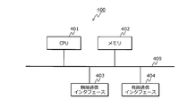
- FIG. 4 is a diagram illustrating an example of a hardware configuration of the base station according to the embodiment.
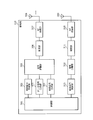
- FIG. 5 is a diagram illustrating an example of a terminal according to the embodiment.
- FIG. 6 is a diagram illustrating an example of a hardware configuration of the terminal according to the embodiment.
- FIG. 7 is a diagram illustrating an example of reference signal transmission from each transmission point according to the embodiment.
- FIG. 8 is a sequence diagram illustrating an example of processing in the communication system according to the embodiment.
- FIG. 1 is a diagram illustrating an example of a wireless communication system according to an embodiment.
- FIG. 2 is a diagram illustrating an example of transmission point selection according to the embodiment.
- FIG. 3 is a diagram of an example of the base station according
- FIG. 9 is a flowchart of an example of bit string generation processing by the terminal according to the embodiment.
- FIG. 10 is a flowchart illustrating an example of processing by the base station according to the embodiment.
- FIG. 11 is a diagram illustrating another example of reference signal transmission from each transmission point according to the embodiment.
- FIG. 12 is a diagram illustrating still another example of the transmission of the reference signal from each transmission point according to the embodiment.
- FIG. 13 is a diagram illustrating an example of reducing the amount of information by notifying a transmission point to be reported by a bit string.
- FIG. 1 is a diagram illustrating an example of a wireless communication system according to an embodiment.
- a communication system 100 includes terminals 101 to 106, base stations 110 and 130, and a central controller 150.
- Base stations 110 and 130 are first wireless devices capable of wireless communication with terminals 101 to 106.
- Terminals 101 to 106 are second wireless devices capable of wireless communication with base stations 110 and 130.
- the base station 110 has transmission points 111 to 127 provided at different positions.
- Each of the transmission points 111 to 127 is a transmission point for forming a cell and for the base station 110 to transmit a radio signal.
- a plurality of transmission points among the transmission points 111 to 127 may cooperate to form one cell.
- Each of the transmission points 111 to 127 may also be used as a reception point for the base station 110 to receive a radio signal.
- the base station 110 and the transmission points 111 to 127 may be connected in accordance with an interface called CPRI (Common Public Radio Interface).
- CPRI Common Public Radio Interface
- the base station 130 has transmission points 131 to 146 provided at different positions. Each of the transmission points 131 to 146 forms a cell and is a transmission point for the base station 130 to transmit a radio signal. A plurality of transmission points among the transmission points 131 to 146 may cooperate to form one cell. Each of the transmission points 131 to 146 may also be used as a reception point for the base station 130 to receive a radio signal.
- the base station 130 and the transmission points 131 to 146 may be connected in accordance with an interface called CPRI (Common Public Radio Interface).
- CPRI Common Public Radio Interface
- an eNB (evolved Node B) defined in 3GPP can be used for each of the base stations 110 and 130.
- eNB evolved Node B
- 3GPP 3rd Generation Partnership Project
- Each of the terminals 101 to 106 transmits and receives a radio signal to and from at least one of the base stations 110 and 130 using at least one of the transmission points 111 to 127 and 131 to 146.
- a UE User Equipment
- 3GPP 3rd Generation Partnership Project
- each of the terminals 101 to 106 is not limited to the UE, and various terminals can be used.
- the central controller 150 controls wireless communication between the base stations 110 and 130 and the terminals 101 to 106.
- MME Mobility Management Entity
- 3GPP 3rd Generation Partnership Project
- the central controller 150 can use various control devices without being limited to the MME.
- the base stations 110 and 130 can arrange small-sized cells with high density by appropriately setting the mutual distance between the transmission points by the transmission points 111 to 127 and 131 to 146. Thereby, the amount of radio traffic that can be accommodated per unit area can be increased. By increasing the number of transmission points, the amount of wireless traffic that can be accommodated per unit area can be further increased. In addition, the base stations 110 and 130 can perform CoMP transmission using a plurality of transmission points to increase a transmission rate by using radio signal interference generated between cells arranged at high density.
- DPS Dynamic Point Selection
- CS / CB Coordinated Scheduling / Coordinated Beam forming
- JT Joint Transmission: Co-transmission
- the base station 110 performs CoMP transmission that simultaneously transmits the same data signal to the terminal 101 using a plurality of transmission points included in the transmission points 111 to 127.
- the base station 110 or the central control device 150 controls CoMP transmission to the terminal 101.
- base stations 110 and 130 perform CoMP transmission in which the same data signal is simultaneously transmitted to terminal 101 using a plurality of transmission points included in transmission points 111 to 127 and 131 to 146. You may go.
- the central controller 150 controls CoMP transmission to the terminal 101.
- the base station 110 performs CoMP transmission that simultaneously transmits the same data signal to the terminal 101 using a plurality of transmission points included in the transmission points 111 to 127, and the base station 110 controls the CoMP transmission. The case will be described.
- the terminal 101 receives wireless data signals transmitted from a plurality of transmission points and synthesized in space.
- Base station 110 performs phase calculation processing on the data signals transmitted from the respective transmission points so that the reception characteristics of the data signals received by terminal 101 are the best.
- the phase calculation processing may be performed independently for each transmission point used for transmission, or may be performed so as to span between transmission points used for transmission.
- the number of transmission points varies.
- the base station 110 reports which transmission point from among the candidate transmission points used for transmission of the data signal to the terminal 101 is used to transmit the data signal to the terminal 101 from the terminal 101 to the base station 110. Determine based on the signal.
- This report signal includes a radio measurement result described later by the terminal 101.
- transmission points 111 to 127 transmission points that are candidates for use in transmitting a data signal to the terminal 101 change as the terminal 101 moves.
- FIG. 2 is a diagram illustrating an example of transmission point selection according to the embodiment.
- selection of a transmission point used for the base station 110 to transmit a data signal to the terminal 101 will be described.
- Transmission points 201 to 218 shown in FIG. 2 are transmission points included in transmission points 111 to 127 shown in FIG. 1, for example.
- the transmission points 201 to 211 included in the range 251 are transmission points in the vicinity of the terminal 101 and are measurement target transmission points of the received power (wireless quality) in the terminal 101.
- P of P + L is the number of transmission points to be reported later.
- L in P + L is the number of non-report target transmission points to be described later.
- the terminal 101 measures the received power for the radio signals from the transmission points 201 to 211 to be measured.
- the received power is, for example, RSRP (Reference Signal Received Power: Reference Signal Received Power) or RSSI (Received Signal Strength Indicator: Received Signal Strength) of the reference signal from the transmission points 201 to 211 to be measured.
- RSRP and RSSI may be defined in TS36.214, which is one of 3GPP specifications, for example.
- the reference signal to be measured may be cell specific or terminal specific.
- the reference signal is not a reference signal used only for the purpose of demodulating the received radio signal, but evaluates the quality and characteristics of the radio space between the radio device transmitting the radio signal and the radio device receiving the radio signal.
- Reference signal for example, CSI RS: Channel State Reference Signal
- a reference signal for example, DRS: Discovery Reference Signal
- the transmission points 212 to 218 not included in the range 251 are transmission points that are farther away from the terminal 101 than the transmission points 201 to 211, for example, and are not transmission power measurement targets at the terminal 101.
- the transmission points 201 to 211 to be measured may be transmission points designated by the base station 110 to the terminal 101. When the terminal 101 moves, all or some of the transmission points 212 to 218 may become new measurement target candidates.
- Transmission points 201 to 206 included in the range 252 are transmission points to be reported to the base station 110 of the measurement result of the received power by the terminal 101.
- the terminal 101 measures the received power with respect to the reference signals transmitted from the transmission points 201 to 206 at a predetermined time period or at a time period instructed from the base station. At this time, interference signal power may be measured.
- the terminal 101 selects report target transmission points 201 to 206 from the measurement target transmission points 201 to 211 based on the measurement result of the received power at the measurement target transmission points 201 to 211.
- the terminal 101 transmits a report signal including information (a bit string described later) indicating the selected P report target transmission points 201 to 206 to the base station 110. Also, the terminal 101 displays the measurement results for the reference signals transmitted from the selected P report target transmission points 201 to 206 in a predetermined time period or a time period instructed from the base station. To the base station 110. In addition to this periodic transmission, the terminal 101 may transmit the measurement result to the base station 110 when requested by the base station 110.
- the P reporting target transmission points 201 to 206 can be, for example, transmission points having a reception power of a predetermined value or more among the measurement target transmission points 201 to 211.
- P is a variable value.
- this predetermined value may be a value set based on the maximum received power among the received powers of the transmission points 201 to 211 to be measured.
- the P report target transmission points 201 to 206 may be P transmission points selected from the measurement target transmission points 201 to 211 in descending order of reception power. In this case, P is a preset value.
- the transmission points 207 to 211 included in the range 251 but not included in the range 252 are non-report target transmission points that are not the report target among the measurement target transmission points 201 to 211.
- Let L be the number of non-reporting target transmission points. In the example shown in FIG. 2, there are five transmission points 207 to 211, and L 5. Although the terminal 101 recognizes the reference signals transmitted by the transmission points 207 to 211, it is not required to continuously measure the reference signals.
- the terminal may start continuous measurement for the reference signal transmitted from the transmission points 207 to 211.
- the received power of the reference signals transmitted from the transmission points 201 to 206 is equal to or lower than a predetermined value or a value instructed by the base station, the reference signals transmitted from the transmission points 207 to 211 are continuous. Measurement may be started.
- the transmission points 201 and 202 are transmission points to be used for transmitting data signals to the terminal 101 at a certain transmission timing.
- the base station 110 selects the transmission points 201 and 202 to be used from the transmission points 201 to 206 to be reported indicated by the bit string included in the report signal transmitted from the terminal 101. Then, the base station 110 performs CoMP transmission in which the same data signal is simultaneously transmitted from the transmission points 201 and 202 to be used to the terminal 101.
- the transmission timing generation period is 1 [ms]
- a wireless data signal is transmitted to the terminal 101 using a time interval of 1 [ms] length at a certain transmission timing.
- the wireless data signal may be transmitted at two continuous transmission timings (that is, using a continuous time interval of 2 [ms] length).
- the base station 110 receives the selection of the transmission points 201 and 202 to be used from the transmission points 201 to 206 to be reported, for example, periodically transmitted from the terminal 101 for the transmission points 201 to 206 to be reported. This is based on the power measurement results.
- the base station 110 uses a transmission point in which the reception power of the reference signal transmitted from these transmission points in the terminal 101 among the transmission points 201 to 206 to be reported is a predetermined value or more. Select as. In this case, N is a variable value. Alternatively, the base station 110 may select N transmission points selected in descending order of reception power at the terminal 101 from among the transmission points 201 to 206 to be reported, as transmission points to be used. In this case, P is a preset value.
- the base station 110 may determine the main transmission point from the selected transmission points to be used.
- the main transmission point is a transmission point used for transmitting downlink control information from the base station 110 to the terminal 101, for example.
- the base station 110 determines the transmission point with the highest received power at the terminal 101 among the selected transmission points to be used as the main transmission point.
- a transmission point different from the main transmission point among the transmission points to be used selected by the base station 110 is a coordinated transmission point that transmits data to the terminal 101 in cooperation with the main transmission point.
- the control information here includes a modulation scheme, a coding rate, HARQ-related information, and the like that are applied to a radio data signal transmitted to the terminal 101.
- the transmission points 203 to 206 are non-use target transmission points that are not selected as use target transmission points at a certain transmission timing among the report target transmission points 201 to 206. At the next transmission timing, either or both of the transmission points 201 and 202 may not be used for transmission, and any of the transmission points 203 to 206 may be used for transmission.
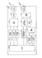
- FIG. 3 is a diagram of an example of the base station according to the embodiment.
- the base station 110 includes a control unit 301, a control signal generation unit 302, a data signal generation unit 303, a reference signal generation unit 304, a signal multiplexing unit 305, and a modulation.
- Unit 306 RF transmission unit 307, and transmission antenna group 308.
- the base station 110 includes a reception antenna 309, an RF reception unit 310, a demodulation unit 311, a signal separation unit 312, and a report signal extraction unit 313.
- the control unit 301 controls communication in the base station 110. For example, the control unit 301 determines a reference signal sequence (pattern) transmitted by the base station 110 and controls the reference signal generation unit 304 to generate a reference signal of the determined sequence. In addition, the control unit 301 controls the control signal generation unit 302 so as to generate a control signal including information on the reference signal indicating the determined reference signal sequence and the like. Further, the control unit 301 controls generation of a data signal by the data signal generation unit 303.
- a reference signal sequence pattern
- the control unit 301 controls the control signal generation unit 302 so as to generate a control signal including information on the reference signal indicating the determined reference signal sequence and the like.
- the control unit 301 controls generation of a data signal by the data signal generation unit 303.
- the control signal generation unit 302 generates a control signal that the base station 110 transmits to a terminal (for example, the terminal 101) under the control of the control unit 301. Then, the control signal generation unit 302 outputs the generated control signal to the signal multiplexing unit 305.
- the control signal generated by the control signal generation unit 302 includes, for example, information on a reference signal transmitted from each transmission point by the base station 110 and information on a transmission point to be used for the terminal.
- the information regarding the transmission point to be used for the target terminal may include, for example, information indicating the main transmission point among the transmission points to be used for the target terminal.
- the data signal generation unit 303 generates a data signal that the base station 110 transmits to the terminal under the control of the control unit 301. Then, the data signal generation unit 303 outputs the generated data signal to the signal multiplexing unit 305.
- the reference signal generation unit 304 generates a reference signal transmitted by the base station 110 under the control of the control unit 301. Then, the reference signal generation unit 304 outputs the generated reference signal to the signal multiplexing unit 305.
- the signal multiplexing unit 305 multiplexes the control signal from the control signal generation unit 302, the data signal from the data signal generation unit 303, and the reference signal from the reference signal generation unit 304. Then, the signal multiplexing unit 305 outputs a signal obtained by multiplexing to the modulation unit 306.
- multiplexing in the signal multiplexing unit 305 for example, multiplexing in at least one of the frequency direction and the time direction can be used.
- a plurality of types of reference signals or a plurality of reference signals that are of the same type but have different parameter values that define a signal configuration code may be code-multiplexed on the same frequency at the same time.
- the modulation unit 306 performs modulation based on the signal output from the signal multiplexing unit 305. Then, modulation section 306 outputs a signal obtained by modulation to RF transmission section 307.
- modulation schemes such as QPSK (Quadrature Phase Shift Keying), 16QAM (Quadrature Amplitude Modulation), and 64 QAM can be used as the modulation scheme in the modulation unit 306, for example.
- the RF transmission unit 307 performs an RF transmission process on the signal output from the modulation unit 306. Then, the RF transmission unit 307 wirelessly transmits the signal subjected to the RF transmission processing via the transmission antenna group 308.
- the RF transmission processing in the RF transmission unit 307 includes, for example, digital / analog signal conversion from a baseband frequency band to an RF (Radio Frequency) band, frequency conversion, signal power amplification, and the like.
- the transmission antenna group 308 forms the transmission points 111 to 127 shown in FIG. 1, for example. That is, each transmission antenna included in the transmission antenna group 308 is connected to the main body of the base station 110 by a wire such as an optical fiber line, for example, and is arranged at a different point. Some functions in the base station 110 may be included in the transmission antenna group 308 arranged at a location distant from the base station and not included in the base station 110. In this case, such functions include an RF transmitter, an optical / electrical signal converter, and a digital / analog signal converter.
- the receiving antenna 309 receives a signal wirelessly transmitted from the outside of the base station 110 (for example, the terminal 101).
- the reception antenna 309 may be a common antenna with the transmission antenna group 308, for example.
- the RF receiver 310 performs an RF reception process on the signal received by the reception antenna 309. Then, the RF reception unit 310 outputs the signal subjected to the RF reception process to the demodulation unit 311.
- the RF reception processing in the RF receiver 310 includes, for example, amplification, frequency conversion from the RF band to the baseband frequency band, analog / digital signal conversion, and the like.
- the demodulator 311 demodulates the signal output from the RF receiver 310.
- Demodulation section 311 outputs the signal obtained by demodulation to signal separation section 312.
- the signal separator 312 demultiplexes the signal output from the demodulator 311. Then, the signal separation unit 312 outputs each signal obtained by the demultiplexing to the report signal extraction unit 313.
- the report signal extraction unit 313 extracts a report signal from the terminal among the signals output from the signal separation unit 312. Then, the report signal extraction unit 313 outputs the extracted report signal to the control unit 301.
- the control unit 301 selects a transmission point to be used for the terminal based on the report signal output from the report signal extraction unit 313. Then, the control unit 301 controls the control signal generation unit 302 so as to generate a control signal including information indicating the selected transmission point. Further, the control unit 301 controls the data signal generation unit 303 so as to generate a data signal transmitted by the selected transmission point. For selection of a transmission point to be used by the control unit 301, in addition to the report signal output from the report signal extraction unit 313, the reception power from the terminal included in each signal output from the signal separation unit 312 is measured. Results may be used.
- a transmitter that transmits reference signals from a plurality of transmission points can be realized by, for example, reference signal generator 304, signal multiplexer 305, modulator 306, RF transmitter 307, and transmission antenna group 308. it can.
- a reception unit that receives a bit string from terminal 101 can be realized by, for example, reception antenna 309, RF reception unit 310, demodulation unit 311, signal separation unit 312 and report signal extraction unit 313.
- FIG. 4 is a diagram illustrating an example of a hardware configuration of the base station according to the embodiment.
- the base station 110 shown in FIG. 3 can be realized by the communication device 400 shown in FIG. 4, for example.
- the communication device 400 includes a CPU 401, a memory 402, a wireless communication interface 403, and a wired communication interface 404.
- the CPU 401, the memory 402, the wireless communication interface 403 and the wired communication interface 404 are connected by a bus 409.
- a CPU (Central Processing Unit) 401 governs overall control of the communication device 400.
- the memory 402 includes, for example, a main memory and an auxiliary memory.
- the main memory is, for example, a RAM (Random Access Memory).
- the main memory is used as a work area for the CPU 401.
- the auxiliary memory is, for example, a nonvolatile memory such as a magnetic disk, an optical disk, or a flash memory.
- Various programs for operating the communication device 400 are stored in the auxiliary memory. The program stored in the auxiliary memory is loaded into the main memory and executed by the CPU 401.
- the wireless communication interface 403 is a communication interface that communicates with the outside of the communication device 400 (for example, a terminal such as the terminal 101) wirelessly.
- the wireless communication interface 403 is controlled by the CPU 401.
- the wired communication interface 404 is a communication interface that communicates with the outside of the communication device 400 (for example, the central control device 150) by wire.
- the wired communication interface 404 is controlled by the CPU 401.
- the modulation unit 306, the RF transmission unit 307, the transmission antenna group 308, the reception antenna 309, the RF reception unit 310, and the demodulation unit 311 illustrated in FIG. 3 can be realized by the wireless communication interface 403, for example.
- FIG. 5 is a diagram illustrating an example of a terminal according to the embodiment. Although the configuration of the terminal 101 will be described in FIG. 5, the configurations of the terminals 102 to 106 are the same as the configuration of the terminal 101. As illustrated in FIG. 5, the terminal 101 according to the embodiment includes a control unit 501, a control signal generation unit 502, a data signal generation unit 503, a report signal generation unit 504, a signal multiplexing unit 505, and a modulation unit. 506, an RF transmission unit 507, and a transmission antenna 508.
- the terminal 101 includes a reception antenna 509, an RF reception unit 510, a signal separation unit 511, a reference signal detection / measurement unit 512, and a reference signal measurement result evaluation unit 513.
- the terminal 101 includes a demodulation unit 514, a signal separation unit 515, a control signal extraction unit 516, and a data signal extraction unit 517.
- the control unit 501 controls communication in the terminal 101. For example, the control unit 501 controls generation of a control signal by the control signal generation unit 502. Further, the control unit 501 controls the generation of the data signal by the data signal generation unit 503. Further, the control unit 501 controls the generation of the report signal by the report signal generation unit 504. In addition, the control unit 501 controls the evaluation of the transmission point to be measured by the reference signal measurement result evaluation unit 513. The control unit 501 controls the detection of the reference signal by the reference signal detection / measurement unit 512.
- the control signal generation unit 502 generates a control signal transmitted from the terminal 101 to the base station (for example, the base station 110) under the control of the control unit 501. Then, the control signal generation unit 502 outputs the generated control signal to the signal multiplexing unit 505.
- the data signal generation unit 503 generates a data signal that the terminal 101 transmits to the base station under the control of the control unit 501. Then, the data signal generation unit 503 outputs the generated data signal to the signal multiplexing unit 505.
- the report signal generation unit 504 generates a report signal that the terminal 101 transmits to the base station under the control of the control unit 501. Then, the report signal generation unit 504 outputs the generated report signal to the signal multiplexing unit 505.
- the report signal generated by the report signal generation unit 504 is information for reporting, to the base station 110, the report target transmission point notified from the reference signal measurement result evaluation unit 513, for example.
- the report signal generated by the report signal generation unit 504 further reports to the base station 110 the transmission point with the highest received power among the transmission points to be reported, notified from the reference signal measurement result evaluation unit 513. It may be a report signal. Further, the report signal generated by the report signal generation unit 504 is a report signal for reporting to the base station 110 the reception power of the transmission point with the highest reception power, notified from the reference signal measurement result evaluation unit 513. Also good.
- the signal multiplexing unit 505 multiplexes the control signal from the control signal generation unit 502, the data signal from the data signal generation unit 503, and the report signal from the report signal generation unit 504. Then, the signal multiplexing unit 505 outputs the signal obtained by multiplexing to the modulation unit 506.
- multiplexing in the signal multiplexing unit 505 for example, multiplexing in at least one of the frequency direction and the time direction can be used.
- Information to be reported that is transmitted in the report signal may be transmitted in the data signal instead of in the report signal. In this case, the data signal containing the information to be reported is transmitted without being multiplexed with the report signal, or is multiplexed with the report signal with other information.
- the modulation unit 506 performs modulation based on the signal output from the signal multiplexing unit 505. Then, modulation section 506 outputs a signal obtained by modulation to RF transmission section 507. For example, various modulation schemes such as QPSK, 16QAM, and 64QAM can be used as the modulation scheme in the modulation unit 506.
- the RF transmission unit 507 performs an RF transmission process on the signal output from the modulation unit 506. Then, the RF transmission unit 507 wirelessly transmits the signal subjected to the RF transmission processing via the transmission antenna 508.
- the RF transmission processing in the RF transmission unit 507 includes, for example, digital / analog signal conversion from the baseband frequency band to the RF band, frequency conversion, amplification, and the like.
- the receiving antenna 509 receives a signal wirelessly transmitted from the outside of the terminal 101 (for example, the base station 110).
- the reception antenna 509 may be a common antenna with the transmission antenna 508, for example.
- the RF reception unit 510 performs an RF reception process on the signal received by the reception antenna 509. Then, the RF reception unit 510 outputs the signal subjected to the RF reception process to the signal separation unit 511.
- the RF reception processing in the RF reception unit 510 includes, for example, amplification, frequency conversion from the RF band to the baseband frequency band, analog / digital signal conversion, and the like.
- the signal separation unit 511 demultiplexes the signal output from the RF reception unit 510. Then, the signal demultiplexing unit 511 outputs the reference signal obtained by demultiplexing to the reference signal detection / measurement unit 512 and outputs other signals obtained by demultiplexing to the demodulation unit 514.
- the reference signal detection / measurement unit 512 performs detection of a reference signal included in each signal output from the signal separation unit 511 and measurement of received power based on the detected reference signal under the control of the control unit 501. .
- each transmission point to be measured for terminal 101 is associated with a different radio resource (for example, subframe). This association is notified from the base station 110, for example.
- the reference signal detection / measurement unit 512 measures the reference signal transmitted from each transmission point of the measurement target by measuring the reception power of the reference signal transmitted by each radio resource associated with each transmission point of the measurement target. Each received power of the signal can be measured. Further, the reference signal detection / measurement unit 512 outputs the reception power measurement result to the reference signal measurement result evaluation unit 513.
- the reference signal measurement result evaluation unit 513 evaluates a transmission point to be measured in the terminal 101 based on the measurement result of the received power output from the reference signal detection / measurement unit 512 under the control of the control unit 501. Then, the reference signal measurement result evaluation unit 513 selects a report target transmission point from the measurement target transmission points based on the evaluation result.
- the reference signal measurement result evaluation unit 513 notifies the report signal generation unit 504 of the selected transmission point of the report target. Further, the reference signal measurement result evaluation unit 513 further transmits the transmission point having the highest received power among the selected transmission points to be reported, and the received power of the transmission point having the highest received power to the report signal generation unit 504. You may be notified.
- the demodulator 514 demodulates the signal output from the signal separator 511.
- Demodulation section 514 outputs a signal obtained by demodulation to signal separation section 515.
- the signal separator 515 demultiplexes the signal output from the demodulator 514. Then, the signal separation unit 515 outputs each signal obtained by the demultiplexing to the control signal extraction unit 516 and the data signal extraction unit 517.
- the control signal extraction unit 516 extracts a control signal from the base station from among the signals output from the signal separation unit 515 under the control of the control unit 501. Then, the control signal extraction unit 516 outputs the extracted control signal to the control unit 501.
- the control signal extracted by the control signal extraction unit 516 includes, for example, information on the reference signal described above, information on a transmission point to be used, and the like.
- the data signal extraction unit 517 extracts the data signal from the base station out of the signals output from the signal separation unit 515 under the control of the control unit 501. Then, the data signal extraction unit 517 outputs the extracted data signal to the control unit 501.
- control unit 501 controls the detection of the reference signal by the reference signal detection / measurement unit 512 based on the information related to the reference signal output from the control signal extraction unit 516. Further, the control unit 501 controls transmission point evaluation in the reference signal measurement result evaluation unit 513 based on the information related to the reference signal output from the control signal extraction unit 516.
- control unit 501 controls the extraction of the control signal by the control signal extraction unit 516 based on the information regarding the transmission point output from the control signal extraction unit 516. Further, the control unit 501 controls the data signal extraction by the data signal extraction unit 517 based on the information regarding the transmission point output from the control signal extraction unit 516.
- measurement units that measure the received power of reference signals respectively transmitted from a plurality of transmission points by base station 110 include, for example, reception antenna 509, RF reception unit 510, signal separation unit 511, and reference signal detection / measurement unit. 512.
- a transmission unit that transmits a bit string to base station 110 can be realized by report signal generation unit 504, signal multiplexing unit 505, modulation unit 506, RF transmission unit 507, and transmission antenna 508.
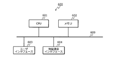
- FIG. 6 is a diagram illustrating an example of a hardware configuration of the terminal according to the embodiment.
- the terminal 101 shown in FIG. 5 can be realized by, for example, the communication device 600 shown in FIG.
- the communication device 600 includes a CPU 601, a memory 602, a user interface 603, and a wireless communication interface 604.
- the CPU 601, the memory 602, the user interface 603, and the wireless communication interface 604 are connected by a bus 609.
- the CPU 601 governs overall control of the communication device 600.
- the memory 602 includes, for example, a main memory and an auxiliary memory.
- the main memory is, for example, a RAM.
- the main memory is used as a work area for the CPU 601.
- the auxiliary memory is a non-volatile memory such as a magnetic disk or a flash memory.
- Various programs for operating the communication device 600 are stored in the auxiliary memory.
- the program stored in the auxiliary memory is loaded into the main memory and executed by the CPU 601.
- the user interface 603 includes, for example, an input device that receives an operation input from the user, an output device that outputs information to the user, and the like.
- the input device can be realized by, for example, a key (for example, a keyboard) or a remote controller.
- the output device can be realized by, for example, a display or a speaker. Further, an input device and an output device may be realized by a touch panel or the like.
- the user interface 603 is controlled by the CPU 601.
- the wireless communication interface 604 is a communication interface that performs communication with the outside of the communication device 600 (for example, a base station such as the base station 110) wirelessly.
- the wireless communication interface 604 is controlled by the CPU 601.
- the control unit 501, control signal generation unit 502, data signal generation unit 503, report signal generation unit 504, and signal multiplexing unit 505 shown in FIG. 5 can be realized by the CPU 601, for example.
- the reference signal measurement result evaluation unit 513, the signal separation unit 515, the control signal extraction unit 516, and the data signal extraction unit 517 illustrated in FIG. 5 can be realized by the CPU 601, for example.
- the modulation unit 506, the RF transmission unit 507, the transmission antenna 508, the reception antenna 509, the RF reception unit 510, the signal separation unit 511, the reference signal detection / measurement unit 512, and the demodulation unit 514 illustrated in FIG. Can be realized.
- FIG. 7 is a diagram illustrating an example of reference signal transmission from each transmission point according to the embodiment.
- the transmission points # 1 to #m to be measured correspond to, for example, P + L transmission points 201 to 211 shown in FIG.
- FIG. 7 shows a subframe of the downlink radio link in the base station 110, and the horizontal axis direction shows the time axis.
- the length of one subframe on the time axis is, for example, 1 [ms].
- Transmission timings 710, 720, 730, and 740 indicate the transmission timings of the reference signals by the transmission points # 1 to # 4, respectively.
- the base station 110 transmits a reference signal every m subframes at each of the transmission points # 1 to #m. Then, the base station 110 performs control so that the subframes for transmitting the reference signals are different at the transmission points # 1 to #m.
- k 0, 1, 2,...
- base station 110 transmits an OFDM symbol in which a reference signal is mapped in transmission point # 1 in the (k * 16 + 1) th subframe. That is, base station 110 transmits OFDM symbols 711, 712,... To which reference signals are mapped in the first subframe, the 17th subframe,.
- the base station 110 transmits an OFDM symbol in which the reference signal is mapped in the (k * 16 + 2) th subframe by the transmission point # 2. That is, the base station 110 transmits OFDM symbols 721, 722,... To which reference signals are mapped in the second subframe, the 18th subframe,.
- base station 110 transmits an OFDM symbol to which a reference signal is mapped in transmission point # 3 in the (k * 16 + 3) th subframe. That is, base station 110 transmits OFDM symbols 731, 732,... To which reference signals are mapped in the third subframe, the 19th subframe,.
- base station 110 transmits an OFDM symbol to which a reference signal is mapped in transmission point # 4 in the (k * 16 + 4) th subframe. That is, base station 110 transmits OFDM symbols 741, 742,... To which reference signals are mapped in the fourth subframe, the twentieth subframe,.
- the base station 110 transmits OFDM symbols to which the reference signals are mapped in the (k * 16 + 5) to (k * 16 + m) subframes for the transmission points # 5 to #m, respectively. Thereby, the base station 110 can map and transmit each reference signal from the transmission points # 1 to #m to a different subframe (timing) depending on the transmission point.
- a reference signal having a sequence (pattern) common to the transmission points # 1 to #m can be used for each reference signal transmitted from the transmission points # 1 to #m by the base station 110.
- the base station 110 periodically transmits a reference signal using a sequence common between transmission points in a certain area on subframes different between adjacent transmission points (every m subframes).
- a common sequence for the reference signal of each transmission point it is possible to reduce radio resources required for notification of the sequence of the reference signal from the base station 110 to the terminal 101.
- cyclic shifts having different lengths between the transmission points may be applied to the reference signals transmitted from the transmission points. By detecting the cyclic shift amount, the terminal can know from which transmission point of the transmission points # 1 to #m the received reference signal is transmitted.
- the period m at which the base station 110 transmits the reference signal at each transmission point can be set according to the arrangement density of the transmission points, for example. For example, as the arrangement density of transmission points increases, the base station 110 can appropriately set reference signals at each transmission point by increasing the value of m and increasing the number of cell repetitions.
- the position where the reference signal is mapped in each subframe can be set in advance, for example, the xth to yth subcarriers on the nth OFDM symbol in the subframe. Further, a plurality of OFDM symbols to which reference signals are mapped may be transmitted in one subframe at each of transmission points # 1 to #m. In addition, a part of the radio data signal may be mapped onto the reference signal so as to be frequency-multiplexed or code-multiplexed on one OFDM symbol to which the reference signal is mapped.
- the terminal 101 can recognize the timing of each subframe based on a synchronization signal transmitted from the base station 110, for example.
- the timing here can be said to be the head position of each subframe in the time domain.
- Terminal 101 then performs scan measurement on the reference signal in the time direction, and identifies a transmission point with the maximum received power among transmission points # 1 to #m. This maximum received power is A [dBm].
- the terminal 101 identifies a transmission point where the received power among the transmission points # 1 to #m is A [dBm] or less and AB [dBm] or more. Thereby, the transmission point whose difference from the largest received power A is equal to or smaller than the predetermined value (B) can be specified as the transmission point to be reported.
- B may be a fixed value or a parameter that the base station 110 notifies the terminal 101 of.
- Terminal 101 has an m-bit bit string indicating a transmission point at which the received power is equal to or lower than A [dBm] and equal to or higher than AB [dBm], and identification information (for example, a cell ID) indicating the transmission point with the highest received power. Are transmitted to the base station 110.
- the bit string is a bitmap (bit arrangement) in which each bit position is associated with each subframe. For example, in the bit string, MSB (Most Significant Bit: most significant bit) corresponds to subframe # 0, and LSB (Least Significant Bit: least significant bit) corresponds to subframe # m-1. Since the transmission points # 1 to #m correspond to different subframes, each bit position of the bit string is associated with each subframe, so that each bit position of the bit string corresponds to each of the transmission points # 1 to #m. is associated with m.
- the relationship between the frame number and m is defined in advance using a formula Is possible.
- a formula Is possible for example, in an LTE system for which specifications are created in 3GPP, one frame is composed of 10 subframes, and a terminal transmits a frame number and subframe through a PBCH (Primary Broadcast Channel) transmitted on a specific subframe. Since the frame number can be grasped, it is possible to define in advance an expression that uniquely determines the relationship among the frame number, the subframe number, and the transmission point number.
- PBCH Primary Broadcast Channel
- the received power at the terminal 101 of the reference signal mapped to the OFDM symbols 711, 712,... Transmitted by the transmission point # 1 is ⁇ 12 [dBm].
- the reception power at the terminal 101 of the reference signal mapped to the OFDM symbols 721, 722,... Transmitted by the transmission point # 2 is ⁇ 8 [dBm].
- the received power at the terminal 101 of the reference signal mapped to the OFDM symbols 731, 732,... Transmitted by the transmission point # 3 is ⁇ 17 [dBm]. Further, it is assumed that the reception power at the terminal 101 of the reference signal mapped to the OFDM symbols 741, 742,... Transmitted by the transmission point # 4 is ⁇ 11 [dBm].
- the transmission points # 1 to #m the transmission points whose reference signal reception power is ⁇ 13 [dBm] or more are transmission points # 1, # 2, and # 4 (reception power is ⁇ 12 [dBm], -8 [dBm], -11 [dBm]) only.
- terminal 101 selects transmission points # 1, # 2, and # 4 as transmission points to be reported, and transmits a report signal including a bit string indicating transmission points # 1, # 2, and # 4 to base station 110.
- the bit string indicating the transmission points # 1, # 2, and # 4 can be, for example, “1101000000000”.
- This bit string is an m-bit bit string corresponding to the number of transmission points # 1 to #m to be measured. The first to mth bits of this bit string indicate whether transmission points # 1 to #m are transmission points to be reported, that is, whether or not the received power is AB or higher.
- bit string “1101000000000000000” is generated.
- the meaning of the bit value can be arbitrarily designed. For example, the bit corresponding to the transmission point may be “0” and the other bits may be “1”.
- the terminal 101 transmits a report signal including this bit string “1101000000000000000” to the base station 110. Thereby, it is possible to notify the base station 110 that the transmission points # 1, # 2, and # 4 among the transmission points # 1 to #m are the transmission points to be reported.
- the base station 110 selects the reporting transmission point from the transmission points # 1 to #m using the maximum received power A as a reference (AB [dBm] or more). B may be notified to the terminal 101 in advance. Since B is a parameter that determines a relative reference based on the maximum received power A, the range of values that B can take can be narrowed. For this reason, since the terminal 101 selects the transmission point to be reported, the information amount of the control signal transmitted from the base station 110 to the terminal 101 can be reduced.
- the terminal 101 may select a transmission point having a reception power of C or more among the transmission points # 1 to #m as a transmission point to be reported.
- C is an absolute reference, unlike the above-described AB, which is a relative reference based on the maximum received power A.
- C is determined by the base station 110, for example, and is notified from the base station 110 to the terminal 101.
- terminal 101 may transmit a report signal including identification information (for example, cell ID) of transmission point # 2 having the maximum received power to base station 110. Thereby, it is possible to notify the base station 110 that the reception power at the transmission point # 2 among the transmission points # 1, # 2, and # 4 to be reported is maximum.
- identification information for example, cell ID
- the base station 110 sets the transmission point # 2 having the maximum received power among the transmission points # 1, # 2, and # 4 to be reported as the main transmission point for the terminal 101, and performs other transmissions Points # 1 and # 4 can be set as coordinated transmission points.
- terminal 101 reports that includes information indicating the bit position on the bit string corresponding to transmission point # 2 having the largest received power, instead of identification information (for example, cell ID) of transmission point # 2 having the largest received power.
- a signal may be transmitted to the base station 110. Thereby, it is possible to notify the base station 110 that the reception power at the transmission point # 2 among the transmission points # 1, # 2, and # 4 to be reported is maximum. Further, the amount of information of the report signal can be reduced as compared with the case where a report signal including identification information (for example, a 9-bit cell ID) of the transmission point # 2 is transmitted. For example, when the bit string is 16 bits as described above, the information indicating the bit position on the bit string corresponding to the transmission point # 2 is realized by 4-bit information indicating one of the 16 bit positions. Can do.
- terminal 101 may transmit a report signal including a measurement result indicating the received power measured for transmission point # 2 to base station 110. Thereby, the received power measured about transmission point # 2 can be notified with respect to the base station 110.
- the base station 110 determines that it is difficult for the base station 110 to transmit the data signal to the terminal 101 when the received power measured for the transmission point # 2 is lower than a predetermined value, for example. be able to.
- a predetermined value for example. be able to.
- the base station 110 determines that it is difficult for the base station 110 to transmit a data signal to the terminal 101. Such as handing over to the small cell base station.
- FIG. 8 is a sequence diagram illustrating an example of processing in the communication system according to the embodiment.
- each step shown in FIG. 8 is executed between the base station 110 and the terminal 101.
- Each step shown in FIG. 8 is performed at the start of communication between base station 110 and terminal 101, for example.
- each step shown in FIG. 8 may be periodically performed while communication is performed between the base station 110 and the terminal 101.
- the content of the information related to the reference signal for example, step S801 can change greatly.
- the base station 110 transmits to the terminal 101 information related to the reference signal that the base station 110 transmits from each transmission point (step S801).
- the information related to the reference signal includes the above-described value of m, a parameter indicating the sequence (pattern) of the reference signal, and the like.
- the base station 110 transmits the value B to the terminal 101 (step S802).
- B is a parameter for selecting a transmission point to be reported on the basis of the maximum received power A described above.
- a downlink channel such as PDSCH (Physical Downlink Shared Channel) can be used.
- the base station 110 may collectively transmit information on the reference signal and the value of B to the terminal 101.
- the terminal 101 detects the reference signal transmitted from each transmission point by the base station 110 based on the information related to the reference signal transmitted in step S801, and measures the received power of the detected reference signal ( Step S803).
- the terminal 101 selects the transmission point to be reported based on the value of B transmitted in step S802 and the measurement result of the received power in step S803. Then, the terminal 101 generates a report signal including a bit string indicating the selected report target transmission point (step S804).
- the report signal generated in step S804 may include, in addition to the bit string, the ID of the transmission point with the maximum received power of the reference signal and the received power of the reference signal from the transmission point. A method of generating a bit string by the terminal 101 will be described later (for example, see FIG. 9).
- the terminal 101 transmits the report signal generated in step S804 to the base station 110 (step S805).
- an uplink channel such as PUCCH (Physical Uplink Control Channel: physical uplink control channel) or PUSCH (Physical Uplink Shared Channel: physical uplink shared channel) can be used.
- the base station 110 sets a transmission point to be used for transmission of a data signal to the terminal 101 (step S806).
- the transmission points to be used are, for example, transmission points corresponding to the transmission points 201 and 202 shown in FIG.
- the base station 110 determines whether or not it is necessary to change at least one of the main transmission point and the coordinated transmission point among the transmission points to be used for the terminal 101.
- the base station 110 determines that at least one of the main transmission point and the coordinated transmission point needs to be changed, the base station 110 changes at least one of the main transmission point and the coordinated transmission point with respect to the terminal 101, and changes the change.
- the control signal shown is transmitted to the terminal 101.
- the terminal 101 need not be notified of the change in the coordinated transmission point.
- the base station 110 determines that neither the main transmission point nor the coordinated transmission point needs to be changed, the base station 110 maintains the current main transmission point and the coordinated transmission point.
- the base station 110 transmits a data signal to the terminal 101 using the transmission points to be used (main transmission point and cooperative transmission point) set in step S806 (step S807).
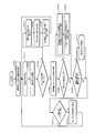
- FIG. 9 is a flowchart of an example of bit string generation processing by the terminal according to the embodiment.
- step S804 shown in FIG. 8 the terminal 101 executes each step shown in FIG. 9 to generate a bit string to be included in the report signal.
- the terminal 101 measures the received power Pi [dBm] of the reference signal in the subframe i for each of the m subframes i (step S901).
- the terminal 101 sets the maximum value in the received power Pi measured in step S901 as A (step S902).
- the terminal 101 determines whether or not the received power Pi is equal to or higher than AB (step S904).
- A is the maximum value among the reception power Pi set in step S902.
- B is a value transmitted from the base station 110 to the terminal 101 in step S802 shown in FIG.
- step S904 if the received power Pi is equal to or higher than AB (step S904: Yes), it can be determined that the transmission point i that transmitted the reference signal in the subframe i satisfies the standard. In this case, the terminal 101 sets the bit Bi to “1” (step S905), and proceeds to step S907.
- Bit Bi is the value of the i-th bit in the above-described bit string, and is information indicating whether or not the transmission point i that transmitted the reference signal in the subframe i satisfies the standard.
- step S904 if the received power Pi is not equal to or higher than AB (step S904: No), it can be determined that the transmission point i that transmitted the reference signal in the subframe i does not satisfy the standard. In this case, the terminal 101 sets the bit Bi to “0” (step S906).
- step S908 the terminal 101 determines whether i is larger than m (step S908). When i is not larger than m (step S908: No), the terminal 101 returns to step S904. When i is larger than m (step S908: Yes), the terminal 101 ends a series of processes.
- Bi arranged in step S905 or step S906 arranged in the order of i is a bit string included in the report signal generated in step S804 shown in FIG.
- FIG. 10 is a flowchart illustrating an example of processing by the base station according to the embodiment.
- the base station 110 according to the embodiment executes, for example, each step shown in FIG. First, the base station 110 transmits information on a reference signal transmitted from each transmission point to the terminal 101 (step S1001).
- the base station 110 transmits a reference signal from each transmission point (step S1002).
- the base station 110 receives a report signal from the terminal 101 (step S1003).
- the base station 110 determines whether or not all bit string values included in the report signal received in step S1003 are zero (step S1004).
- step S1004 if all the bit string values are zero (step S1004: Yes), it can be determined that all of the current measurement target transmission points for the terminal 101 do not satisfy the standard. In this case, the base station 110 resets the measurement target transmission point candidates for the terminal 101 (step S1005).
- the base station 110 generates a new reference signal (step S1006).
- the new reference signal is a reference signal whose sequence has been changed, for example.
- the base station 110 generates information related to the reference signal generated in step S1006 and transmits the information to the terminal 101 (step S1007), and returns to step S1002.
- step S1004 if the values of the bit strings are not all zero (step S1004: No), it can be determined that at least one of the current measurement target transmission points for the terminal 101 satisfies the criterion. In this case, the base station 110 identifies the transmission point with the maximum reception power among the transmission points currently being measured for the terminal 101 based on the report signal received in step S1003 (step S1008).
- the base station 110 determines whether or not the transmission point with the maximum received power identified in step S1008 is the same as the current main transmission point for the terminal 101 (step S1009). When the transmission point with the maximum received power is the same as the main transmission point (step S1009: Yes), the base station 110 proceeds to step S1012. When the transmission point with the maximum received power is not the same as the main transmission point (step S1009: No), the base station 110 performs the main transmission so that the transmission point with the maximum reception power identified at step S1008 is the main transmission point. The point is changed (step S1010). Next, the base station 110 transmits a control signal indicating a change of the main transmission point to the terminal 101 (step S1011).
- the base station 110 determines whether or not it is necessary to change the coordinated transmission point for the terminal 101 (step S1012).
- the determination in step S1012 is, for example, whether the transmission point excluding the main transmission point of the terminal 101 among the P transmission points indicated by the bit string included in the report signal is the same as the current cooperative transmission point for the terminal 101 Judgment can be made based on whether or not.
- step S1012 If it is determined in step S1012 that no change is required (step S1012: No), the base station 110 proceeds to step S1014.
- step S1012: Yes the base station 110 changes the cooperative transmission point for the terminal 101 (step S1013).
- the base station 110 may transmit control information indicating the change of the cooperative transmission point to the terminal 101.
- the base station 110 determines whether there is data to be transmitted to the terminal 101 (step S1014). If there is no data to be transmitted to the terminal 101 (step S1014: No), the base station 110 returns to step S1002. When there is data to be transmitted to the terminal 101 (step S1014: Yes), the base station 110 transmits the data signal to the terminal 101 (step S1015), and returns to step S1002.
- FIG. 11 is a diagram illustrating another example of reference signal transmission from each transmission point according to the embodiment.
- FIG. 11 the same parts as those shown in FIG.
- FIG. 7 illustrates the case where the reference signals of the transmission points # 1 to #m are transmitted in each subframe, a subframe in which the reference signal of any transmission point is not transmitted may be provided.
- a transmission timing 1110 illustrated in FIG. 11 indicates the transmission timing of the reference signal by the transmission point # 11.
- the OFDM symbols 1111 and 1112 are OFDM symbols to which the reference signal is mapped, which is transmitted from the base station 110 at the transmission point # 11.
- base station 110 transmits reference signals of transmission points # 1 to #m using only the first m subframes in each of 10240 subframe periods. That is, if base station 110 transmits each reference signal of transmission points # 1 to #m using the 1st to m-th subframes, then it does not transmit the reference signal until 10240th subframes. Then, base station 110 transmits each reference signal of transmission points # 1 to #m using the 10241th to m + 10240 subframes.
- the number of frames is 1024 from 0 to 1023, and 1024 frame numbers from 0 to 1023 are repeated for every 1024 frames.
- the terminal 101 can know the number of the currently received frame and the number of the subframe in the frame through the PBCH transmitted on the specific subframe. By determining in advance an expression indicating the relationship between the frame number and the number of the frame in which the reference signal is transmitted, the terminal can grasp from which subframe of which frame the reference signal is transmitted.
- FIG. 11 shows a case where the reference signals of transmission points # 1 to #m are transmitted continuously in time, but the base station 110 transmits the reference signals of transmission points # 1 to #m. You may make it transmit at intervals mutually.
- FIG. 12 is a diagram illustrating still another example of the transmission of the reference signal from each transmission point according to the embodiment. 7 and 11, the case has been described in which each reference signal from transmission points # 1 to #m is assigned to a different subframe (time resource) for transmission, but the radio resource to which each reference signal is assigned is a time resource. Not limited to only.
- FIG. 12 a case will be described in which reference signals from transmission points # 1 to #m are allocated to different time resources and frequency resources for transmission.
- the horizontal axis indicates the frequency axis
- the vertical axis indicates the time axis.
- the transmission points to be measured for terminal 101 are 16 transmission points # 1 to # 16.
- Reference signals 1201 to 1216 are reference signals transmitted by transmission points # 1 to # 16, respectively.
- reference signals 1201 to 1216 from transmission points # 1 to # 16 are transmitted such that their time and frequency are different from each other.
- terminal 101 receives a plurality of reference signals 1201 transmitted from transmission point # 1 at different frequencies (for example, one or a plurality of subcarriers) at time T1, and receives each of the plurality of received reference signals 1201. The average value of received power is calculated. Thereby, the reception power at the terminal 101 of the reference signal 1201 from the transmission point # 1 is calculated.
- terminal 101 calculates received power by calculating an average value of received power of each reference signal transmitted at times T2 to T16, similarly for transmission points # 2 to # 16. Also, reference signals 1201 to 1216 from transmission points # 1 to # 16 are transmitted again from time T17 following time T16.
- FIG. 12 illustrates the case where the base station 110 transmits the reference signals from the transmission points # 1 to #m by assigning them to different time resources and frequency resources. Further, the base station 110 may allocate and transmit the reference signals from the transmission points # 1 to #m to different frequency resources. In this case, the base station 110 allocates and transmits each reference signal from the transmission points # 1 to #m to the same time resource.
- FIG. 13 is a diagram illustrating an example of reducing the amount of information by notifying a transmission point to be reported by a bit string.
- the table 1300 shown in FIG. 13 is required for notification in the case where the notification of the transmission point to be reported is performed by each ID of the transmission point to be reported as in the conventional case and the case where the transmission point is performed by a bit string as in the communication system 100.
- the amount of information (number of bits) is shown.
- the size of an ID for example, a cell ID
- indicating a transmission point is 9 bits.
- m 16 corresponding to the number of transmission points # 1 to #m to be measured, and the number of IDs that the terminal 101 reports to the base station 110, that is, the number of transmission points to be reported is 5.
- 5 ⁇ 9 bits 45 bits are required.
- the amount of information required for notification increases as the number of transmission points to be reported increases.
- notification is performed using a bit string as in the communication system 100, the amount of information does not increase even when the number of transmission points to be reported increases.
- the terminal 101 can transmit the bit string without notifying the base station 110 of the size of the radio resource for transmitting the bit string. For this reason, the information content of the control signal between the terminal 101 and the base station 110 can be reduced.
- the terminal 101 measures the received power of the reference signal transmitted from each transmission point to be measured.
- the terminal 101 is a bit string in which each bit position is associated with a transmission point to be measured, and a bit string indicating whether or not the received power satisfies a predetermined condition for each transmission point to be measured is a base station 110.
- the reporting target transmission point can be notified to the base station 110 with a small amount of information. For this reason, it is possible to suppress an increase in the amount of radio resources required for reporting information on the transmission target candidates to be reported.
- the transmission point notification by this bit string is not limited to the notification of the transmission point to be reported from the terminal 101 to the base station 110, but can also be used for the transmission point notification from the base station 110 to the terminal 101, for example. .
- the base station 110 may notify the terminal 101 of transmission points to be measured (for example, transmission points 201 to 211 shown in FIG. 2) using a bit string.
- the base station 110 transmits a bit string associated with each transmission point (for example, the transmission points 201 to 218 shown in FIG. 2) of the transmission point group in which each bit position includes the transmission point to be measured. Transmit to terminal 101.
- This bit string is a bit string indicating whether or not each transmission point of the transmission point group is included in the transmission point to be measured.
- the terminal 101 specifies a measurement target transmission point based on the bit string transmitted by the base station 110, and measures the received power of each reference signal transmitted from the measurement target transmission point by the base station 110. Thereby, for example, even if there are many transmission points to be measured, the transmission points to be measured can be notified to the terminal 101 with a small amount of information. For this reason, it is possible to suppress an increase in the amount of radio resources required for notification of information on transmission point candidates to be measured.
- the wireless device As described above, according to the wireless communication system, the wireless device, and the processing method, it is possible to suppress an increase in the amount of wireless resources required for notification of transmission point candidate information.
- reporting the specific IDs of more transmission points to the wireless network side is limited due to the limited amount of uplink radio resources. For this reason, it is conceivable that the improvement in characteristics that can be expected by reducing the size of radio cells (that is, increasing the arrangement density of transmission points) cannot be realized sufficiently.
- the terminal reports information to the radio network side that can suppress an increase in the amount of uplink radio resources used for reporting purposes and can identify many transmission points. Is possible.
Landscapes
- Engineering & Computer Science (AREA)
- Computer Networks & Wireless Communication (AREA)
- Signal Processing (AREA)
- Quality & Reliability (AREA)
- Mobile Radio Communication Systems (AREA)
Abstract
基地局(110)は、送信点(111~127)の中から選択した各送信点を協調させてデータ信号を送信する。また、基地局(110)は、送信点(111~127)からそれぞれ参照信号を送信する。端末(101)は、基地局(110)によって送信点(111~127)からそれぞれ送信された参照信号の受信電力を測定し、各ビット位置がそれぞれ送信点(111~127)と対応付けられたビット列であって、送信点(111~127)のそれぞれについて受信電力が所定条件を満たすか否かを示すビット列を基地局(110)へ送信する。
Description
本発明は、無線通信システム、無線装置および処理方法に関する。
従来、無線基地局(これ以降、基地局と略記)から一つの無線端末(これ以降、端末と略記)への無線データ送信に複数の送信点を、一つの端末から基地局へ送信される無線データ信号の受信に複数の受信点を用いるCoMP送受信(Coordinated Multiple-Point transmission and reception:多地点協調通信)方式(これ以降、CoMPと略記)が知られている。CoMPを用いる無線通信システムにおいては、送信点の配置密度を大きくすることにより無線容量を増加することが可能であると考えられている。
また、符号分割多元接続スペクトル拡散セルラ通信システムにおいて、各基地局が他基地局について異なる擬似ランダム雑音オフセットとなる共通のパイロット信号を送信する技術が知られている(たとえば、下記特許文献1参照。)。
また、複数のCSI-RS(Channel State Information-Reference Signal:チャネル状態情報参照信号)を異なるOFDM(Orthogonal Frequency Division Multiplexing:直交周波数分割多重)シンボルを用いて時間多重して送信する技術が知られている(たとえば、下記特許文献2参照。)。
しかしながら、上述した従来技術であるCoMPを採用する無線セルラ通信システムにおいて、送信点が高密度に配置され、一つの端末の周辺に多くの送信点が存在する状況では、本端末に対する無線データ信号の送信に使用される可能性がある送信点候補の数が多くなり、本端末に対する無線データ信号送信のために使用される本端末が希望する送信点候補に関する情報を本端末が基地局に対し通知するために要する無線リソースの量が大きくなる場合がある。
1つの側面では、本発明は、送信点候補の情報の通知に要する無線リソースの量の増大を抑制することができる無線通信システム、無線装置および処理方法を提供することを目的とする。
上述した課題を解決し、目的を達成するため、本発明の一側面によれば、複数の送信点に含まれる各送信点を協調させてデータ信号を送信する第1無線装置が、前記複数の送信点からそれぞれ参照信号を送信し、第2無線装置が、前記第1無線装置によって前記複数の送信点からそれぞれ送信された参照信号の受信電力を測定し、各ビット位置がそれぞれ前記複数の送信点と対応付けられたビット列であって、前記複数の送信点のそれぞれについて前記受信電力が所定条件を満たすか否かを示すビット列を前記第1無線装置へ送信する無線通信システム、無線装置および処理方法が提案される。
本発明の一側面によれば、送信点候補の情報の通知に要する無線リソースの量の増大を抑制することができるという効果を奏する。
以下に図面を参照して、本発明にかかる無線通信システム、無線装置および処理方法の実施の形態を詳細に説明する。
(実施の形態)
(実施の形態にかかる無線通信システム)
図1は、実施の形態にかかる無線通信システムの一例を示す図である。図1に示すように、実施の形態にかかる通信システム100は、端末101~106と、基地局110,130と、中央制御装置150と、を含む。基地局110,130は、端末101~106との間で無線通信が可能な第1無線装置である。端末101~106は、基地局110,130との間で無線通信が可能な第2無線装置である。
(実施の形態にかかる無線通信システム)
図1は、実施の形態にかかる無線通信システムの一例を示す図である。図1に示すように、実施の形態にかかる通信システム100は、端末101~106と、基地局110,130と、中央制御装置150と、を含む。基地局110,130は、端末101~106との間で無線通信が可能な第1無線装置である。端末101~106は、基地局110,130との間で無線通信が可能な第2無線装置である。
基地局110は、それぞれ異なる位置に設けられた送信点111~127を有する。送信点111~127のそれぞれは、セルを形成し、基地局110が無線信号を送信するための送信点である。送信点111~127の中の複数の送信点が協調して一つのセルを形成してもよい。また、送信点111~127のそれぞれは、基地局110が無線信号を受信するための受信ポイントとしても用いられてもよい。基地局110と送信点111~127の間は、たとえば、CPRI(Common Public Radio Interface)と呼ばれるインタフェースに準じて接続されてもよい。
基地局130は、それぞれ異なる位置に設けられた送信点131~146を有する。送信点131~146のそれぞれは、セルを形成し、基地局130が無線信号を送信するための送信点である。送信点131~146の中の複数の送信点が協調して一つのセルを形成してもよい。また、送信点131~146のそれぞれは、基地局130が無線信号を受信するための受信ポイントとしても用いられてもよい。基地局130と送信点131~146の間は、たとえば、CPRI(Common Public Radio Interface)と呼ばれるインタフェースに準じて接続されてもよい。
基地局110,130のそれぞれには、一例としては、3GPPに規定されたeNB(evolved Node B)を用いることができる。ただし、基地局110,130のそれぞれには、eNBに限らず各種の基地局を用いることができる。
端末101~106のそれぞれは、送信点111~127,131~146のうちの少なくともいずれかを用いて、基地局110,130のうちの少なくともいずれかとの間で無線信号の送受信を行う。端末101~106のそれぞれには、たとえば3GPPに規定されたUE(User Equipment)を用いることができる。ただし、端末101~106のそれぞれには、UEに限らず各種の端末を用いることができる。
中央制御装置150は、基地局110,130による端末101~106との間の無線通信を制御する。中央制御装置150には、たとえば3GPPに規定されたMME(Mobility Management Entity:移動性管理エンティティ)を用いることができる。ただし、中央制御装置150には、MMEに限らず各種の制御装置を用いることができる。
基地局110,130は、送信点111~127,131~146によって送信点間の相互距離を適切に設定することにより小サイズのセルを高密度で配置することができる。これにより、単位面積あたりの無線トラフィック収容可能量を増やすことができる。送信点の数を増やすことにより、更に、単位面積あたりの無線トラフィック収容可能量を増やすことができる。また、基地局110,130は、複数の送信点を用いることにより、高密度で配置したセル間で発生する無線信号の干渉を利用して伝送レートを高めるCoMP送信を行うことが可能である。
基地局110,130によるCoMP送信には、DPS(Dynamic Point Selection)方式、CS/CB(Coordinated Scheduling/Coordinated Beam forming)方式、JT(Joint Transmission:ジョイントトランスミッション)方式などの各種の方式のCoMP送信を用いることができる。以下、主に、基地局110,130によるCoMP送信にDPS方式のCoMP送信を用いる場合について説明する。
通信システム100においては、たとえば、基地局110が、送信点111~127に含まれる複数の送信点を用いて端末101に対して同一のデータ信号を同時に送信するCoMP送信を行う。この場合は、基地局110または中央制御装置150が、端末101へのCoMP送信の制御を行う。
または、通信システム100においては、基地局110,130が、送信点111~127,131~146に含まれる複数の送信点を用いて端末101に対して同一のデータ信号を同時に送信するCoMP送信を行ってもよい。この場合は、中央制御装置150が、端末101へのCoMP送信の制御を行う。
以下、基地局110が送信点111~127に含まれる複数の送信点を用いて端末101に対して同一のデータ信号を同時に送信するCoMP送信を行い、基地局110が該CoMP送信の制御を行う場合について説明する。
端末101は、複数の送信点から送信され空間上で合成された無線データ信号を受信する。基地局110は、端末101が受信するデータ信号の受信特性が最良になるように、それぞれの送信点から送信するデータ信号に対して位相演算処理を行う。位相演算処理は、送信に使用される送信点ごとに独立して行っても、あるいは、送信に使用される送信点の間にまたがるように行ってもよい。
また、端末101の周辺の環境変化、端末101の移動、基地局110の各送信点の負荷状態の変化に伴い、端末101に対してデータ信号を送信する際に使用される送信点、使用される送信点の数等が変化する。
基地局110は、端末101へのデータ信号の送信に用いる候補の送信点のうちのいずれの送信点を用いて端末101へデータ信号を送信するかを、端末101から基地局110へ送信する報告信号に基づいて決定する。この報告信号には、端末101による後述の無線測定結果が含まれる。送信点111~127のうちの端末101へのデータ信号の送信に用いる候補となる送信点は、端末101の移動等にともなって変化する。
(実施の形態にかかる送信点の選択)
図2は、実施の形態にかかる送信点の選択の一例を示す図である。図2においては、基地局110が端末101へデータ信号を送信するために使用する送信点の選択について説明する。図2に示す送信点201~218は、たとえば図1に示した送信点111~127に含まれる送信点である。
図2は、実施の形態にかかる送信点の選択の一例を示す図である。図2においては、基地局110が端末101へデータ信号を送信するために使用する送信点の選択について説明する。図2に示す送信点201~218は、たとえば図1に示した送信点111~127に含まれる送信点である。
範囲251に含まれる送信点201~211は、端末101の周辺における各送信点であって、端末101における受信電力(無線品質)の測定対象の送信点である。測定対象の送信点の数をP+L個とする。図2に示す例では、送信点201~211の11個であり、P+L=11である。P+LのうちのPは、後述の報告対象の送信点の数である。P+LのうちのLは、後述の非報告対象の送信点の数である。端末101は、測定対象の送信点201~211からの無線信号についての受信電力の測定を行う。
ここで、受信電力は、たとえば測定対象の送信点201~211からの参照信号の端末101におけるRSRP(Reference Signal Received Power:基準信号受信電力)やRSSI(Received Signal Strength Indicator:受信信号強度)等である。RSRPやRSSIは、たとえば、3GPPの仕様書のひとつであるTS36.214の中で定義されているものであってもよい。測定対象となる参照信号はセル固有のものであっても、端末固有のものであってもよい。なお、参照信号は、受信した無線信号を復調する目的だけで使用する参照信号ではなく、無線信号を送信する無線装置とその無線信号を受信する無線装置の間の無線空間の品質や特性を評価する目的で送信される参照信号(たとえばCSI RS:Channel State Information Reference Signal)、あるいは、無線装置が他の無線装置の存在を検出することを目的として送信される参照信号(たとえばDRS:Discovery Reference Signal)とすることができる。
範囲251に含まれない送信点212~218は、たとえば送信点201~211よりも端末101から離れた送信点であって、端末101における受信電力の測定対象ではない送信点である。なお、測定対象の送信点201~211は、基地局110が端末101に対して指示した送信点であってもよい。端末101が移動した場合、送信点212~218の中の全て、あるいは、一部が、新たな測定対象候補になることもある。
範囲252に含まれる送信点201~206は、端末101による受信電力の測定結果の基地局110への報告対象の送信点である。端末101は、送信点201~206から送信される参照信号に対し、事前に決められた時間周期、あるいは、基地局から指示された時間周期で、受信電力の測定を行う。この際、干渉信号電力の測定を行ってもよい。端末101は、測定対象の送信点201~211についての受信電力の測定結果に基づいて、測定対象の送信点201~211の中から報告対象の送信点201~206を選択する。報告対象の送信点の数をP個とする。図2に示す例では、送信点201~206の6個であり、P=6である。
また、端末101は、選択したP個の報告対象の送信点201~206を示す情報(後述のビット列)を含む報告信号を基地局110へ送信する。また、端末101は、選択したP個の報告対象の送信点201~206から送信される参照信号に対する測定の結果を、事前に決められた時間周期、あるいは、基地局から指示された時間周期で、基地局110へ送信する。この周期的送信に加え、基地局110から要求された時に、端末101は測定結果を基地局110へ送信してもよい。
P個の報告対象の送信点201~206は、たとえば測定対象の送信点201~211のうちの受信電力が所定値以上の送信点とすることができる。この場合は、Pは可変の値となる。この所定値は、後述のように、測定対象の送信点201~211の各受信電力のうちの最大の受信電力に基づいて設定される値であってもよい。または、P個の報告対象の送信点201~206は、測定対象の送信点201~211の中から受信電力が大きい順に選択したP個の送信点であってもよい。この場合は、Pは予め設定された値となる。
範囲251に含まれるが範囲252に含まれない送信点207~211は、測定対象の送信点201~211のうちの報告対象ではない非報告対象の送信点である。非報告対象の送信点の数をL個とする。図2に示す例では、送信点207~211の5個であり、L=5である。端末101は、送信点207~211が送信する参照信号を認識しているが、それらの参照信号に対する測定を連続して測定することは要求されてはいない。
ただし、たとえば、送信点201~206から送信される参照信号の受信電力が低下した際、端末は自主的に送信点207~211から送信される参照信号に対する連続測定を開始してもよいし、あるいは、送信点201~206から送信される参照信号の受信電力が事前に決められた値あるいは基地局から指示された値以下になった場合、送信点207~211から送信される参照信号に対する連続測定を開始してもよい。
送信点201,202は、ある送信タイミングで端末101へデータ信号を送信する使用対象の送信点である。基地局110は、端末101から送信された報告信号に含まれるビット列が示す報告対象の送信点201~206の中から、使用対象の送信点201,202を選択する。そして、基地局110は、使用対象の送信点201,202から同一のデータ信号を端末101へ同時に送信するCoMP送信を行う。使用対象の送信点の数をN個とする。図2に示す例では、送信点201,202の2個であり、N=2である。
3GPPのLTEシステムにおいては、送信タイミングの発生周期は1[ms]であり、端末101に対し、ある送信タイミングで単発的に1[ms]長の時間区間を利用して無線データ信号の送信を行ってもいいし、たとえば2つの連続する送信タイミング(すなわち2[ms]長の連続した時間区間を利用)で無線データ信号の送信を行ってもいい。
基地局110は、報告対象の送信点201~206からの使用対象の送信点201,202の選択を、たとえば、端末101から周期的に送信される、報告対象の送信点201~206についての受信電力の測定結果に基づいて行う。
一例としては、基地局110は、報告対象の送信点201~206のうちの端末101におけるこれらの送信点から送信される参照信号の受信電力が所定値以上である送信点を使用対象の送信点として選択する。この場合は、Nは可変の値となる。または、基地局110は、報告対象の送信点201~206の中から端末101における受信電力が大きい順に選択したN個の送信点を使用対象の送信点として選択してもよい。この場合は、Pは予め設定された値となる。
また、基地局110は、選択した使用対象の送信点の中から主送信点を決定してもよい。主送信点は、たとえば基地局110から端末101への下りの制御情報の送信に用いられる送信点である。たとえば、基地局110は、選択した使用対象の送信点のうちの端末101における受信電力が最も大きい送信点を主送信点に決定する。基地局110によって選択された使用対象の送信点のうちの主送信点と異なる送信点は、主送信点と協調して端末101へデータを送信する協調送信点となる。ここでの制御情報とは、端末101に対し送信される無線データ信号に適用されている変調方式や符号化率、HARQ関連の情報などが含まれる。
送信点203~206は、報告対象の送信点201~206のうち、ある送信タイミングにおいて使用対象の送信点として選択されなかった非使用対象の送信点である。次の送信タイミングでは、送信点201,202のいずれかまたは両方が送信に使用されず、送信点203~206の中のいずれかが送信に使用される可能性がある。非使用対象の送信点の数をM個とする。図2に示す例では、送信点203~206の4個であり、M=4である。また、Mの値は可変であり、次の送信タイミングでは、たとえば、3あるいは5という値をとることもありうる。すなわち、各送信タイミングにおいて、端末101に対する無線データ信号の送信に使用される送信点の数は可変である。
(実施の形態にかかる基地局)
図3は、実施の形態にかかる基地局の一例を示す図である。図3においては基地局110の構成について説明するが、基地局130の構成も基地局110の構成と同様である。図3に示すように、実施の形態にかかる基地局110は、制御部301と、制御信号生成部302と、データ信号生成部303と、参照信号生成部304と、信号多重部305と、変調部306と、RF送信部307と、送信アンテナ群308と、を備える。また、基地局110は、受信アンテナ309と、RF受信部310と、復調部311と、信号分離部312と、報告信号抽出部313と、を備える。
図3は、実施の形態にかかる基地局の一例を示す図である。図3においては基地局110の構成について説明するが、基地局130の構成も基地局110の構成と同様である。図3に示すように、実施の形態にかかる基地局110は、制御部301と、制御信号生成部302と、データ信号生成部303と、参照信号生成部304と、信号多重部305と、変調部306と、RF送信部307と、送信アンテナ群308と、を備える。また、基地局110は、受信アンテナ309と、RF受信部310と、復調部311と、信号分離部312と、報告信号抽出部313と、を備える。
制御部301は、基地局110における通信の制御を行う。たとえば、制御部301は、基地局110が送信する参照信号のシーケンス(パターン)を決定し、決定したシーケンスの参照信号を生成するように参照信号生成部304を制御する。また、制御部301は、決定した参照信号のシーケンス等を示す、参照信号に関する情報を含む制御信号を生成するように制御信号生成部302を制御する。また、制御部301は、データ信号生成部303によるデータ信号の生成を制御する。
制御信号生成部302は、制御部301からの制御により、基地局110が端末(たとえば端末101)へ送信する制御信号の生成を行う。そして、制御信号生成部302は、生成した制御信号を信号多重部305へ出力する。制御信号生成部302が生成する制御信号には、たとえば、基地局110が各送信点から送信する参照信号に関する情報や、端末についての使用対象の送信点に関する情報が含まれる。対象の端末についての使用対象の送信点に関する情報には、たとえば対象の端末についての使用対象の送信点のうちの主送信点を示す情報が含まれていてもよい。
データ信号生成部303は、制御部301からの制御により、基地局110が端末へ送信するデータ信号の生成を行う。そして、データ信号生成部303は、生成したデータ信号を信号多重部305へ出力する。参照信号生成部304は、制御部301からの制御により、基地局110が送信する参照信号の生成を行う。そして、参照信号生成部304は、生成した参照信号を信号多重部305へ出力する。
信号多重部305は、制御信号生成部302からの制御信号と、データ信号生成部303からのデータ信号と、参照信号生成部304からの参照信号と、を多重化する。そして、信号多重部305は、多重化により得られた信号を変調部306へ出力する。信号多重部305における多重化には、たとえば、周波数方向および時間方向の少なくともいずれかによる多重化を用いることができる。複数の種類の参照信号、あるいは、同一種類ではあるが信号構成符号を定義するパラメータの値が異なる複数の参照信号を同一時間同一周波数上において符号多重してもよい。
変調部306は、信号多重部305から出力された信号に基づく変調を行う。そして、変調部306は、変調により得られた信号をRF送信部307へ出力する。変調部306における変調方式には、たとえばQPSK(Quadrature Phase Shift Keying:四位相偏移変調)、16QAM(Quadrature Amplitude Modulation:直角位相振幅変調)、64QAMなどの各種の変調方式を用いることができる。
RF送信部307は、変調部306から出力された信号のRF送信処理を行う。そして、RF送信部307は、RF送信処理を行った信号を、送信アンテナ群308を介して無線送信する。RF送信部307におけるRF送信処理には、たとえば、ベースバンド周波数帯からRF(Radio Frequency:高周波)帯へのデジタル/アナログ信号変換や周波数変換や信号電力増幅などが含まれる。
送信アンテナ群308は、たとえば図1に示した送信点111~127を形成する。すなわち、送信アンテナ群308に含まれる各送信アンテナは、たとえば光ファイバー回線等の有線で基地局110の本体部に接続され、それぞれ異なる地点に配置される。基地局110内の一部の機能を、基地局から離れた場所に配置される送信アンテナ群308の中に含め基地局110の中に入れないようにしてもよい。この場合、そのような機能として、RF送信部、光/電気信号変換部、デジタル/アナログ信号変換部等がある。
受信アンテナ309は、基地局110の外部(たとえば端末101)から無線送信された信号を受信する。受信アンテナ309は、たとえば送信アンテナ群308と共通のアンテナであってもよい。RF受信部310は、受信アンテナ309によって受信された信号のRF受信処理を行う。そして、RF受信部310は、RF受信処理を行った信号を復調部311へ出力する。RF受信部310におけるRF受信処理には、たとえば、増幅や、RF帯からベースバンド周波数帯への周波数変換や、アナログ/デジタル信号変換などが含まれる。
復調部311は、RF受信部310から出力された信号の復調を行う。そして、復調部311は、復調により得られた信号を信号分離部312へ出力する。信号分離部312は、復調部311から出力された信号を多重分離する。そして、信号分離部312は、多重分離により得られた各信号を報告信号抽出部313へ出力する。報告信号抽出部313は、信号分離部312から出力された各信号のうちの端末からの報告信号を抽出する。そして、報告信号抽出部313は、抽出した報告信号を制御部301へ出力する。
制御部301は、報告信号抽出部313から出力された報告信号に基づいて、端末についての使用対象の送信点を選択する。そして、制御部301は、選択した送信点を示す情報を含む制御信号を生成するように制御信号生成部302を制御する。また、制御部301は、選択した送信点によって送信されるデータ信号を生成するようにデータ信号生成部303を制御する。制御部301による使用対象の送信点の選択には、報告信号抽出部313から出力された報告信号に加えて、信号分離部312から出力された各信号に含まれる、端末からの受信電力の測定結果を用いてもよい。
基地局110において、複数の送信点からそれぞれ参照信号を送信する送信部は、たとえば参照信号生成部304、信号多重部305、変調部306、RF送信部307および送信アンテナ群308により実現することができる。また、基地局110において、端末101からのビット列を受信する受信部は、たとえば受信アンテナ309、RF受信部310、復調部311、信号分離部312および報告信号抽出部313により実現することができる。
(実施の形態にかかる基地局のハードウェア構成)
図4は、実施の形態にかかる基地局のハードウェア構成の一例を示す図である。図3に示した基地局110は、たとえば図4に示す通信装置400により実現することができる。通信装置400は、CPU401と、メモリ402と、無線通信インタフェース403と、有線通信インタフェース404と、を備える。CPU401、メモリ402、無線通信インタフェース403および有線通信インタフェース404は、バス409により接続される。
図4は、実施の形態にかかる基地局のハードウェア構成の一例を示す図である。図3に示した基地局110は、たとえば図4に示す通信装置400により実現することができる。通信装置400は、CPU401と、メモリ402と、無線通信インタフェース403と、有線通信インタフェース404と、を備える。CPU401、メモリ402、無線通信インタフェース403および有線通信インタフェース404は、バス409により接続される。
CPU(Central Processing Unit)401は、通信装置400の全体の制御を司る。メモリ402には、たとえばメインメモリおよび補助メモリが含まれる。メインメモリは、たとえばRAM(Random Access Memory)である。メインメモリは、CPU401のワークエリアとして使用される。補助メモリは、たとえば磁気ディスク、光ディスク、フラッシュメモリなどの不揮発メモリである。補助メモリには、通信装置400を動作させる各種のプログラムが記憶されている。補助メモリに記憶されたプログラムは、メインメモリにロードされてCPU401によって実行される。
無線通信インタフェース403は、無線によって通信装置400の外部(たとえば端末101などの端末)との間で通信を行う通信インタフェースである。無線通信インタフェース403は、CPU401によって制御される。
有線通信インタフェース404は、有線によって通信装置400の外部(たとえば中央制御装置150)との間で通信を行う通信インタフェースである。有線通信インタフェース404は、CPU401によって制御される。
図3に示した制御部301、制御信号生成部302、データ信号生成部303、参照信号生成部304、信号多重部305、信号分離部312および報告信号抽出部313は、たとえばCPU401により実現することができる。図3に示した変調部306、RF送信部307、送信アンテナ群308、受信アンテナ309、RF受信部310および復調部311は、たとえば無線通信インタフェース403により実現することができる。
(実施の形態にかかる端末)
図5は、実施の形態にかかる端末の一例を示す図である。図5においては端末101の構成について説明するが、端末102~106の構成も端末101の構成と同様である。図5に示すように、実施の形態にかかる端末101は、制御部501と、制御信号生成部502と、データ信号生成部503と、報告信号生成部504と、信号多重部505と、変調部506と、RF送信部507と、送信アンテナ508と、を備える。また、端末101は、受信アンテナ509と、RF受信部510と、信号分離部511と、参照信号検出・測定部512と、参照信号測定結果評価部513と、を備える。また、端末101は、復調部514と、信号分離部515と、制御信号抽出部516と、データ信号抽出部517と、を備える。
図5は、実施の形態にかかる端末の一例を示す図である。図5においては端末101の構成について説明するが、端末102~106の構成も端末101の構成と同様である。図5に示すように、実施の形態にかかる端末101は、制御部501と、制御信号生成部502と、データ信号生成部503と、報告信号生成部504と、信号多重部505と、変調部506と、RF送信部507と、送信アンテナ508と、を備える。また、端末101は、受信アンテナ509と、RF受信部510と、信号分離部511と、参照信号検出・測定部512と、参照信号測定結果評価部513と、を備える。また、端末101は、復調部514と、信号分離部515と、制御信号抽出部516と、データ信号抽出部517と、を備える。
制御部501は、端末101における通信の制御を行う。たとえば、制御部501は、制御信号生成部502による制御信号の生成を制御する。また、制御部501は、データ信号生成部503によるデータ信号の生成を制御する。また、制御部501は、報告信号生成部504による報告信号の生成を制御する。また、制御部501は、参照信号測定結果評価部513による測定対象の送信点の評価を制御する。また、制御部501は、参照信号検出・測定部512による参照信号の検出を制御する。
制御信号生成部502は、制御部501からの制御により、端末101が基地局(たとえば基地局110)へ送信する制御信号の生成を行う。そして、制御信号生成部502は、生成した制御信号を信号多重部505へ出力する。
データ信号生成部503は、制御部501からの制御により、端末101が基地局へ送信するデータ信号の生成を行う。そして、データ信号生成部503は、生成したデータ信号を信号多重部505へ出力する。
報告信号生成部504は、制御部501からの制御により、端末101が基地局へ送信する報告信号の生成を行う。そして、報告信号生成部504は、生成した報告信号を信号多重部505へ出力する。報告信号生成部504が生成する報告信号は、たとえば、参照信号測定結果評価部513から通知された報告対象の送信点を基地局110へ報告する情報である。
また、報告信号生成部504が生成する報告信号は、さらに、参照信号測定結果評価部513から通知された、報告対象の送信点のうちの受信電力が最も大きい送信点を基地局110へ報告する報告信号であってもよい。また、報告信号生成部504が生成する報告信号は、さらに、参照信号測定結果評価部513から通知された、受信電力が最も大きい送信点の受信電力を基地局110へ報告する報告信号であってもよい。
信号多重部505は、制御信号生成部502からの制御信号と、データ信号生成部503からのデータ信号と、報告信号生成部504からの報告信号と、を多重化する。そして、信号多重部505は、多重化により得られた信号を変調部506へ出力する。信号多重部505における多重化には、たとえば、周波数方向および時間方向の少なくともいずれかによる多重化を用いることができる。なお、報告信号の中に入れて送信される報告する情報を報告信号の中ではなくデータ信号の中に入れて送信してもよい。この場合、報告する情報が入れられたデータ信号は報告信号と多重されずに送信されるか、あるいは他の情報が入れられた報告信号と多重して送信される。
変調部506は、信号多重部505から出力された信号に基づく変調を行う。そして、変調部506は、変調により得られた信号をRF送信部507へ出力する。変調部506における変調方式には、一例としては、QPSK、16QAM、64QAMなど各種の変調方式を用いることができる。
RF送信部507は、変調部506から出力された信号のRF送信処理を行う。そして、RF送信部507は、RF送信処理を行った信号を、送信アンテナ508を介して無線送信する。RF送信部507におけるRF送信処理には、たとえば、ベースバンド周波数帯からRF帯へのデジタル/アナログ信号変換、周波数変換や増幅などが含まれる。
受信アンテナ509は、端末101の外部(たとえば基地局110)から無線送信された信号を受信する。受信アンテナ509は、たとえば送信アンテナ508と共通のアンテナであってもよい。RF受信部510は、受信アンテナ509によって受信された信号のRF受信処理を行う。そして、RF受信部510は、RF受信処理を行った信号を信号分離部511へ出力する。RF受信部510におけるRF受信処理には、たとえば、増幅や、RF帯からベースバンド周波数帯への周波数変換、アナログ/デジタル信号変換などが含まれる。
信号分離部511は、RF受信部510から出力された信号を多重分離する。そして、信号分離部511は、多重分離により得られた参照信号を参照信号検出・測定部512へ出力し、多重分離により得られた他の信号を復調部514へ出力する。
参照信号検出・測定部512は、制御部501からの制御により、信号分離部511から出力された各信号に含まれる参照信号の検出と、検出した参照信号に基づく受信電力の測定と、を行う。たとえば、端末101についての測定対象の各送信点は、それぞれ異なる無線リソース(たとえばサブフレーム)と対応付けられている。この対応付けは、たとえば基地局110から通知される。このため、参照信号検出・測定部512は、測定対象の各送信点と対応付けられた各無線リソースによって送信された参照信号の受信電力を測定することにより、測定対象の各送信点からの参照信号の受信電力をそれぞれ測定することができる。また、参照信号検出・測定部512は、受信電力の測定結果を参照信号測定結果評価部513へ出力する。
参照信号測定結果評価部513は、制御部501からの制御により、参照信号検出・測定部512から出力された受信電力の測定結果に基づいて、端末101における測定対象の送信点の評価を行う。そして、参照信号測定結果評価部513は、評価結果に基づいて、測定対象の送信点の中から報告対象の送信点を選択する。
また、参照信号測定結果評価部513は、選択した報告対象の送信点を報告信号生成部504へ通知する。また、参照信号測定結果評価部513は、さらに、選択した報告対象の送信点のうちの受信電力が最も大きい送信点や、該受信電力が最も大きい送信点の受信電力を報告信号生成部504へ通知してもよい。
復調部514は、信号分離部511から出力された信号の復調を行う。そして、復調部514は、復調により得られた信号を信号分離部515へ出力する。信号分離部515は、復調部514から出力された信号の多重分離を行う。そして、信号分離部515は、多重分離により得られた各信号を制御信号抽出部516およびデータ信号抽出部517へ出力する。
制御信号抽出部516は、制御部501からの制御により、信号分離部515から出力された各信号のうちの、基地局からの制御信号を抽出する。そして、制御信号抽出部516は、抽出した制御信号を制御部501へ出力する。制御信号抽出部516が抽出する制御信号には、たとえば、上述した参照信号に関する情報や、使用対象の送信点に関する情報などが含まれる。
データ信号抽出部517は、制御部501からの制御により、信号分離部515から出力された各信号のうちの、基地局からのデータ信号を抽出する。そして、データ信号抽出部517は、抽出したデータ信号を制御部501へ出力する。
たとえば、制御部501は、制御信号抽出部516から出力された参照信号に関する情報に基づいて、参照信号検出・測定部512による参照信号の検出を制御する。また、制御部501は、制御信号抽出部516から出力された参照信号に関する情報に基づいて、参照信号測定結果評価部513における送信点の評価を制御する。
また、制御部501は、制御信号抽出部516から出力された送信点に関する情報に基づいて、制御信号抽出部516による制御信号の抽出を制御する。また、制御部501は、制御信号抽出部516から出力された送信点に関する情報に基づいて、データ信号抽出部517によるデータ信号の抽出を制御する。
端末101において、基地局110により複数の送信点からそれぞれ送信された参照信号の受信電力を測定する測定部は、たとえば受信アンテナ509、RF受信部510、信号分離部511および参照信号検出・測定部512により実現することができる。また、端末101において、ビット列を基地局110へ送信する送信部は、報告信号生成部504、信号多重部505、変調部506、RF送信部507および送信アンテナ508により実現することができる。
(実施の形態にかかる端末のハードウェア構成)
図6は、実施の形態にかかる端末のハードウェア構成の一例を示す図である。図5に示した端末101は、たとえば図6に示す通信装置600により実現することができる。通信装置600は、CPU601と、メモリ602と、ユーザインタフェース603と、無線通信インタフェース604と、を備える。CPU601、メモリ602、ユーザインタフェース603および無線通信インタフェース604は、バス609により接続される。
図6は、実施の形態にかかる端末のハードウェア構成の一例を示す図である。図5に示した端末101は、たとえば図6に示す通信装置600により実現することができる。通信装置600は、CPU601と、メモリ602と、ユーザインタフェース603と、無線通信インタフェース604と、を備える。CPU601、メモリ602、ユーザインタフェース603および無線通信インタフェース604は、バス609により接続される。
CPU601は、通信装置600の全体の制御を司る。メモリ602には、たとえばメインメモリおよび補助メモリが含まれる。メインメモリは、たとえばRAMである。メインメモリは、CPU601のワークエリアとして使用される。補助メモリは、たとえば磁気ディスク、フラッシュメモリなどの不揮発メモリである。補助メモリには、通信装置600を動作させる各種のプログラムが記憶されている。補助メモリに記憶されたプログラムは、メインメモリにロードされてCPU601によって実行される。
ユーザインタフェース603は、たとえば、ユーザからの操作入力を受け付ける入力デバイスや、ユーザへ情報を出力する出力デバイスなどを含む。入力デバイスは、たとえばキー(たとえばキーボード)やリモコンなどにより実現することができる。出力デバイスは、たとえばディスプレイやスピーカなどにより実現することができる。また、タッチパネルなどによって入力デバイスおよび出力デバイスを実現してもよい。ユーザインタフェース603は、CPU601によって制御される。
無線通信インタフェース604は、無線によって通信装置600の外部(たとえば基地局110などの基地局)との間で通信を行う通信インタフェースである。無線通信インタフェース604は、CPU601によって制御される。
図5に示した制御部501、制御信号生成部502、データ信号生成部503、報告信号生成部504および信号多重部505は、たとえばCPU601により実現することができる。図5に示した参照信号測定結果評価部513、信号分離部515、制御信号抽出部516およびデータ信号抽出部517は、たとえばCPU601により実現することができる。図5に示した変調部506、RF送信部507、送信アンテナ508、受信アンテナ509、RF受信部510、信号分離部511、参照信号検出・測定部512および復調部514は、たとえば無線通信インタフェース604により実現することができる。
(実施の形態にかかる各送信点からの参照信号の送信)
図7は、実施の形態にかかる各送信点からの参照信号の送信の一例を示す図である。図7においては、端末101における測定対象の送信点がm個の送信点#1~#mである場合について説明する。mは2以上の自然数であり、任意に設定可能である(たとえばm={16,32,64})。図7に示す例ではm=16とする。測定対象の送信点#1~#mは、たとえば図2に示したP+L個の送信点201~211に対応する。
図7は、実施の形態にかかる各送信点からの参照信号の送信の一例を示す図である。図7においては、端末101における測定対象の送信点がm個の送信点#1~#mである場合について説明する。mは2以上の自然数であり、任意に設定可能である(たとえばm={16,32,64})。図7に示す例ではm=16とする。測定対象の送信点#1~#mは、たとえば図2に示したP+L個の送信点201~211に対応する。
図7は、基地局110における下り無線リンクのサブフレームを示し、横軸方向は時間軸を示す。1個のサブフレームの時間軸上での長さは、たとえば、1[ms]である。送信タイミング710,720,730,740は、それぞれ送信点#1~#4による参照信号の送信タイミングを示している。
また、図7に示す例では、基地局110は、送信点#1~#mのそれぞれにおいて、mサブフレームごとに参照信号を送信する。そして、基地局110は、送信点#1~#mのそれぞれにおいて、参照信号を送信するサブフレームが異なるように制御する。以下、k=0,1,2,…とする。
たとえば、送信タイミング710に示すように、基地局110は、送信点#1により、第(k*16+1)サブフレームにおいて、参照信号をマッピングしたOFDMシンボルを送信する。すなわち、基地局110は、送信点#1により、第1サブフレーム、第17サブフレーム、…において、参照信号をマッピングしたOFDMシンボル711,712,…を送信する。
また、送信タイミング720に示すように、基地局110は、送信点#2により、第(k*16+2)サブフレームにおいて、参照信号をマッピングしたOFDMシンボルを送信する。すなわち、基地局110は、送信点#2により、第2サブフレーム、第18サブフレーム、…において、参照信号をマッピングしたOFDMシンボル721,722,…を送信する。
また、送信タイミング730に示すように、基地局110は、送信点#3により、第(k*16+3)サブフレームにおいて、参照信号をマッピングしたOFDMシンボルを送信する。すなわち、基地局110は、送信点#3により、第3サブフレーム、第19サブフレーム、…において、参照信号をマッピングしたOFDMシンボル731,732,…を送信する。
また、送信タイミング740に示すように、基地局110は、送信点#4により、第(k*16+4)サブフレームにおいて、参照信号をマッピングしたOFDMシンボルを送信する。すなわち、基地局110は、送信点#4により、第4サブフレーム、第20サブフレーム、…において、参照信号をマッピングしたOFDMシンボル741,742,…を送信する。
また、基地局110は、送信点#5~#mについても同様に、それぞれ第(k*16+5)~(k*16+m)サブフレームにおいて、それぞれ参照信号をマッピングしたOFDMシンボルを送信する。これにより、基地局110は、送信点#1~#mからの各参照信号を、送信点によって異なるサブフレーム(タイミング)にマッピングして送信することができる。
また、基地局110が送信点#1~#mから送信する各参照信号には、送信点#1~#mの間で共通のシーケンス(パターン)の参照信号を用いることができる。このように、基地局110は、ある一定エリア内の送信点間で共通のシーケンスを用いる参照信号を、隣接する送信点間で異なるサブフレーム上で周期的(mサブフレームごと)に送信する。各送信点の参照信号に共通のシーケンスを用いることにより、基地局110から端末101への参照信号のシーケンスの通知に要する無線リソースを少なくすることができる。また、送信点#1~#mの間で共通のシーケンスの参照信号を用いる際、送信点間で異なる長さの巡回シフトを各送信点から送信される参照信号に対し施してもよい。端末は、巡回シフト量を検出することにより、受信した参照信号が送信点#1~#mの中のどの送信点から送信されたのかを知ることが可能になる。
基地局110が各送信点において参照信号を送信する周期mは、たとえば送信点の配置密度に応じて設定することができる。たとえば、送信点の配置密度が大きくなるにつれ、mの値を大きくしてセル繰り返し数を大きくすることで、基地局110が各送信点において参照信号を適切に設定することができる。
また、各サブフレームにおける参照信号がマッピングされる位置は、たとえばサブフレーム内の第n番目のOFDMシンボル上のx番目からy番目のサブキャリアなど、予め設定しておくことができる。また、送信点#1~#mのそれぞれにおいて、参照信号がマッピングされたOFDMシンボルが一つのサブフレーム内で複数個送信されてもよい。また、参照信号がマッピングされた一つのOFDMシンボル上に、無線データ信号の一部が参照信号に対し周波数多重あるいは符号多重されるようにマッピングされてもよい。
端末101は、たとえば基地局110から送信される同期信号に基づいて各サブフレームのタイミングを認識することができる。ここでいうタイミングとは、時間領域における各サブフレームの先頭位置ということができる。そして、端末101は、時間方向に参照信号に対してスキャン測定を行い、送信点#1~#mのうちの受信電力が最大となる送信点を特定する。この最大の受信電力をA[dBm]とする。
また、端末101は、送信点#1~#mのうちの受信電力がA[dBm]以下、かつA-B[dBm]以上となる送信点を特定する。これにより、最も大きい受信電力Aとの差が所定値(B)以下である送信点を報告対象の送信点として特定することができる。Bは、固定値としてもよいし、基地局110が端末101へ通知するパラメータとしてもよい。
端末101は、受信電力がA[dBm]以下、かつA-B[dBm]以上となる送信点を示すmビットのビット列と、受信電力が最大の送信点を示す識別情報(たとえばセルID)と、を含む報告信号を基地局110へ送信する。
ビット列は、各ビット位置が各サブフレームに対応付けられたビットマップ(ビット配列)である。たとえば、ビット列は、MSB(Most Significant Bit:最上位ビット)がサブフレーム#0に対応し、LSB(Least Significant Bit:最下位ビット)がサブフレーム#m-1に対応付けられる。そして、送信点#1~#mはそれぞれ異なるサブフレームに対応しているため、ビット列の各ビット位置が各サブフレームに対応付けられることにより、ビット列の各ビット位置がそれぞれ送信点#1~#mに対応付けられる。
端末101が受信したサブフレームのサブフレーム番号と送信点番号(#1から#m)の関係を端末101が把握できるようにするために、たとえば、フレーム番号とmの関係を事前に式で定義することが可能である。たとえば、3GPPで仕様が作成されるLTEシステムにおいては、1フレームは10サブフレームで構成され、特定のサブフレーム上で送信されるPBCH(Primary Broadcast Channel:プライマリー報知チャネル)を通じて端末はフレーム番号とサブフレーム番号を把握できるので、フレーム番号とサブフレーム番号と送信点番号の関係が一意に決まる式を事前に定義しておくことが可能である。
図7に示す例では、送信点#1によって送信されたOFDMシンボル711,712,…にマッピングされた参照信号の端末101における受信電力が-12[dBm]であったとする。また、送信点#2によって送信されたOFDMシンボル721,722,…にマッピングされた参照信号の端末101における受信電力が-8[dBm]であったとする。
また、送信点#3によって送信されたOFDMシンボル731,732,…にマッピングされた参照信号の端末101における受信電力が-17[dBm]であったとする。また、送信点#4によって送信されたOFDMシンボル741,742,…にマッピングされた参照信号の端末101における受信電力が-11[dBm]であったとする。
そして、送信点#1~#mのうちの、参照信号の受信電力が最大であった送信点が送信点#2(受信電力=-8[dBm])であったとする。また、B=5であるとする。この場合は、上述したA-Bは、A-B=-8-5=-13となる。
送信点#1~#mのうちの、参照信号の受信電力が-13[dBm]以上である送信点は、送信点#1,#2,#4(それぞれ受信電力が-12[dBm]、-8[dBm]、-11[dBm])のみであったとする。
この場合は、端末101は、報告対象の送信点として送信点#1,#2,#4を選択し、送信点#1,#2,#4を示すビット列を含む報告信号を基地局110へ送信する。送信点#1,#2,#4を示すビット列は、たとえば、“1101000000000000”とすることができる。このビット列は、測定対象の送信点#1~#mの数に対応するmビットのビット列である。そして、このビット列の第1~第mビットは、それぞれ送信点#1~#mが報告対象の送信点であるか、すなわち受信電力がA-B以上であるか否かを示している。
上述したように送信点#1,#2,#4のみが報告対象の送信点である場合は、第1,第2,第4ビットのみが“1”であり、残りのビットが“0”である上述したビット列“1101000000000000”が生成される。なお、ビットの値の意味は任意に設計可能であり、たとえば送信点に対応するビットが“0”であり、他のビットが“1”であってもよい。
端末101は、このビット列“1101000000000000”を含む報告信号を基地局110へ送信する。これにより、送信点#1~#mのうちの送信点#1,#2,#4が報告対象の送信点であることを基地局110に通知することができる。
また、上述のように、送信点#1~#mの中から、最大の受信電力Aを基準(A-B[dBm]以上)として報告対象の送信点を選択することで、基地局110は事前にBを端末101へ通知しておけばよい。Bは、最大の受信電力Aに基づく相対的な基準を決定するパラメータであるため、Bのとり得る値の範囲は狭くすることができる。このため、端末101が報告対象の送信点を選択するために基地局110が端末101へ送信する制御信号の情報量を少なくすることができる。
また、たとえば基地局110がJT方式のCoMP送信を行う場合は、端末101における受信電力の差が小さくなる送信点を組み合わせることにより伝送特性がよくなる。たとえば受信電力差が1[dB]となる各送信点をJT方式のCoMP送信における送信点と組み合わせる場合は、B=1と設定することにより、いずれの送信点が好ましいかを、ビット列により基地局110に通知することが可能になる。
また、端末101は、送信点#1~#mのうちの受信電力がC以上の送信点を報告対象の送信点として選択してもよい。Cは、最大の受信電力Aに基づく相対基準である上述したA-Bと異なり、絶対的な基準である。Cは、たとえば基地局110によって決定され、基地局110から端末101へ通知される。
また、端末101は、ビット列に加えて、受信電力が最大の送信点#2の識別情報(たとえばセルID)を含む報告信号を基地局110へ送信してもよい。これにより、基地局110に対して、報告対象の送信点#1,#2,#4のうちの送信点#2の受信電力が最大であることを通知することができる。
これに対して、基地局110は、たとえば、報告対象の送信点#1,#2,#4のうちの受信電力が最大の送信点#2を端末101についての主送信点とし、他の送信点#1,#4を協調送信点に設定することができる。
または、端末101は、受信電力が最大の送信点#2の識別情報(たとえばセルID)に代えて、受信電力が最大の送信点#2に対応するビット列上のビット位置を示す情報を含む報告信号を基地局110へ送信してもよい。これにより、基地局110に対して、報告対象の送信点#1,#2,#4のうちの送信点#2の受信電力が最大であることを通知することができる。また、送信点#2の識別情報(たとえば9ビットのセルID)を含む報告信号を送信する場合に比べて、報告信号の情報量を少なくすることができる。たとえば、ビット列が上述のように16ビットである場合は、送信点#2に対応するビット列上のビット位置を示す情報は、16通りのビット位置のいずれかを示す4ビットの情報によって実現することができる。
また、端末101は、ビット列および送信点#2の識別情報に加えて、送信点#2について測定した受信電力を示す測定結果を含む報告信号を基地局110へ送信してもよい。これにより、基地局110に対して、送信点#2について測定した受信電力を通知することができる。
これに対して、基地局110は、たとえば、送信点#2について測定した受信電力が所定値を下回っている場合は、基地局110による端末101へのデータ信号の送信が困難であると判断することができる。たとえば、基地局110がフェムトセル等のスモールセルである場合に、基地局110は、基地局110による端末101へのデータ信号の送信が困難であると判断すると、端末101をマクロ基地局や近接のスモールセル基地局へハンドオーバさせるなどの処理を行うことができる。
(実施の形態にかかる通信システムにおける処理)
図8は、実施の形態にかかる通信システムにおける処理の一例を示すシーケンス図である。実施の形態にかかる通信システム100においては、たとえば、基地局110と端末101との間において、図8に示す各ステップが実行される。図8に示す各ステップは、たとえば、基地局110と端末101との間における通信の開始時に行われる。また、図8に示す各ステップは、基地局110と端末101との間において通信が行われている間に周期的に行われてもよい。特に端末101が移動し、端末101に対し無線データ信号を送信可能な潜在的送信点候補が変化する時、参照信号に関する情報(たとえばステップS801)の内容が大きく変わりうる。
図8は、実施の形態にかかる通信システムにおける処理の一例を示すシーケンス図である。実施の形態にかかる通信システム100においては、たとえば、基地局110と端末101との間において、図8に示す各ステップが実行される。図8に示す各ステップは、たとえば、基地局110と端末101との間における通信の開始時に行われる。また、図8に示す各ステップは、基地局110と端末101との間において通信が行われている間に周期的に行われてもよい。特に端末101が移動し、端末101に対し無線データ信号を送信可能な潜在的送信点候補が変化する時、参照信号に関する情報(たとえばステップS801)の内容が大きく変わりうる。
まず、基地局110は、基地局110が各送信点から送信する参照信号に関する情報を端末101へ送信する(ステップS801)。参照信号に関する情報には、上述したmの値や参照信号のシーケンス(パターン)を示すパラメータなどが含まれる。
また、基地局110が、Bの値を端末101へ送信する(ステップS802)。Bは、上述した最大の受信電力Aを基準として報告対象の送信点を選択するためのパラメータである。ステップS801,S802における送信には、たとえばPDSCH(Physical Downlink Shared Channel:物理下りリンク共有チャネル)などの下りリンクのチャネルを用いることができる。
また、基地局110は、参照信号に関する情報およびBの値をまとめて端末101へ送信してもよい。
つぎに、端末101が、ステップS801によって送信された参照信号に関する情報に基づいて、基地局110が各送信点から送信する参照信号の検出を行い、検出した参照信号の受信電力の測定を行う(ステップS803)。
つぎに、端末101が、ステップS802によって送信されたBの値と、ステップS803による受信電力の測定結果と、に基づいて、上述した報告対象の送信点を選択する。そして、端末101は、選択した報告対象の送信点を示すビット列を含む報告信号を生成する(ステップS804)。ステップS804によって生成される報告信号には、ビット列に加えて、参照信号の受信電力が最大の送信点のIDや、該送信点からの参照信号の受信電力が含まれていてもよい。端末101によるビット列の生成方法については後述する(たとえば図9参照)。
つぎに、端末101が、ステップS804によって生成した報告信号を基地局110へ送信する(ステップS805)。ステップS805による送信には、たとえば、PUCCH(Physical Uplink Control Channel:物理上りリンク制御チャネル)やPUSCH(Physical Uplink Shared Channel:物理上りリンク共有チャネル)などの上りリンクのチャネルを用いることができる。
つぎに、基地局110が、端末101へのデータ信号の送信に使用する使用対象の送信点の設定を行う(ステップS806)。使用対象の送信点は、たとえば図2に示した送信点201,202に対応する送信点である。ステップS806において、基地局110は、たとえば、端末101についての使用対象の送信点のうちの主送信点および協調送信点の少なくともいずれかの変更を要するか否かを判断する。
基地局110は、主送信点および協調送信点の少なくともいずれかの変更を要すると判断した場合は、端末101に対して主送信点および協調送信点の少なくともいずれかの変更を行い、該変更を示す制御信号を端末101へ送信する。ただし、主送信点の変更は無いが協調送信点の変更だけが生じた場合、基本的には、協調送信点の変更を端末101に通知しなくてもよい。また、基地局110は、主送信点および協調送信点のいずれの変更も要しないと判断した場合は、現状の主送信点および協調送信点を維持する。
つぎに、基地局110が、ステップS806によって設定された使用対象の送信点(主送信点および協調送信点)を用いて端末101へデータ信号を送信する(ステップS807)。
(実施の形態にかかる端末によるビット列の生成処理)
図9は、実施の形態にかかる端末によるビット列の生成処理の一例を示すフローチャートである。端末101は、図8に示したステップS804において、図9に示す各ステップを実行することにより、報告信号に含めるビット列を生成する。図9において、iは、m個のサブフレームに対応するインデクスである(i={1,2,…,m})。
図9は、実施の形態にかかる端末によるビット列の生成処理の一例を示すフローチャートである。端末101は、図8に示したステップS804において、図9に示す各ステップを実行することにより、報告信号に含めるビット列を生成する。図9において、iは、m個のサブフレームに対応するインデクスである(i={1,2,…,m})。
まず、端末101は、m個のサブフレームiのそれぞれについて、サブフレームiにおける参照信号の受信電力Pi[dBm]を測定する(ステップS901)。つぎに、端末101は、ステップS901によって測定した受信電力Piの中の最大値をAとして設定する(ステップS902)。
つぎに、端末101は、インデクスiを初期化(i=1)する(ステップS903)。つぎに、端末101は、受信電力PiがA-B以上であるか否かを判断する(ステップS904)。Aは、ステップS902によって設定された受信電力Piの中の最大値である。Bは、図8に示したステップS802によって基地局110から端末101へ送信された値である。
ステップS904において、受信電力PiがA-B以上である場合(ステップS904:Yes)は、サブフレームiにおいて参照信号を送信した送信点iが基準を満たすと判断することができる。この場合は、端末101は、ビットBiを“1”に設定し(ステップS905)、ステップS907へ移行する。ビットBiは、上述したビット列におけるi番目のビットの値であり、サブフレームiにおいて参照信号を送信した送信点iが基準を満たすか否かを示す情報である。
ステップS904において、受信電力PiがA-B以上でない場合(ステップS904:No)は、サブフレームiにおいて参照信号を送信した送信点iが基準を満たさないと判断することができる。この場合は、端末101は、ビットBiを“0”に設定する(ステップS906)。
つぎに、端末101は、iをインクリメント(i=i+1)する(ステップS907)。つぎに、端末101は、iがmより大きいか否かを判断する(ステップS908)。iがmより大きくない場合(ステップS908:No)は、端末101は、ステップS904へ戻る。iがmより大きい場合(ステップS908:Yes)は、端末101は、一連の処理を終了する。この時点で、ステップS905またはステップS906により設定したBiをiの順に並べたものが、図8に示したステップS804によって生成される報告信号に含まれるビット列となる。
(実施の形態にかかる基地局による処理)
図10は、実施の形態にかかる基地局による処理の一例を示すフローチャートである。実施の形態にかかる基地局110は、たとえば図10に示す各ステップを実行する。まず、基地局110は、基地局110が各送信点から送信する参照信号に関する情報を端末101へ送信する(ステップS1001)。
図10は、実施の形態にかかる基地局による処理の一例を示すフローチャートである。実施の形態にかかる基地局110は、たとえば図10に示す各ステップを実行する。まず、基地局110は、基地局110が各送信点から送信する参照信号に関する情報を端末101へ送信する(ステップS1001)。
つぎに、基地局110は、各送信点から参照信号を送信する(ステップS1002)。つぎに、基地局110は、端末101からの報告信号を受信する(ステップS1003)。つぎに、基地局110は、ステップS1003によって受信した報告信号に含まれるビット列の値が全てゼロであるか否かを判断する(ステップS1004)。
ステップS1004において、ビット列の値が全てゼロである場合(ステップS1004:Yes)は、端末101についての現在の測定対象の送信点の全てが基準を満たさなかったと判断することができる。この場合は、基地局110は、端末101についての測定対象の送信点の候補を再設定する(ステップS1005)。
また、基地局110は、新たな参照信号を生成する(ステップS1006)。新たな参照信号は、たとえばシーケンスを変更した参照信号である。つぎに、基地局110は、ステップS1006によって生成した参照信号に関する情報の生成および端末101への送信を行い(ステップS1007)、ステップS1002へ戻る。
ステップS1004において、ビット列の値が全てゼロでない場合(ステップS1004:No)は、端末101についての現在の測定対象の送信点の少なくともいずれかが基準を満たしたと判断することができる。この場合は、基地局110は、ステップS1003によって受信した報告信号に基づいて、端末101についての現在の測定対象の送信点のうちの受信電力が最大の送信点を特定する(ステップS1008)。
つぎに、基地局110は、ステップS1008によって特定した受信電力が最大の送信点が、端末101についての現在の主送信点と同一であるか否かを判断する(ステップS1009)。受信電力が最大の送信点が主送信点と同一である場合(ステップS1009:Yes)は、基地局110は、ステップS1012へ移行する。受信電力が最大の送信点が主送信点と同一でない場合(ステップS1009:No)は、基地局110は、ステップS1008によって特定した受信電力が最大の送信点を主送信点とするように主送信点の変更を行う(ステップS1010)。つぎに、基地局110は、主送信点の変更を示す制御信号を端末101へ送信する(ステップS1011)。
つぎに、基地局110は、端末101についての協調送信点の変更を要するか否かを判断する(ステップS1012)。ステップS1012の判断は、たとえば、報告信号に含まれるビット列が示すP個の送信点のうちの端末101の主送信点を除く送信点が、端末101についての現在の協調送信点と同一であるか否かによって判断することができる。
ステップS1012において、変更を要しないと判断した場合(ステップS1012:No)は、基地局110は、ステップS1014へ移行する。変更を要すると判断した場合(ステップS1012:Yes)は、基地局110は、端末101についての協調送信点の変更を行う(ステップS1013)。このとき、たとえば、基地局110は、協調送信点の変更を示す制御情報を端末101へ送信してもよい。
つぎに、基地局110は、端末101へ送信するデータがあるか否かを判断する(ステップS1014)。端末101へ送信するデータがない場合(ステップS1014:No)は、基地局110は、ステップS1002へ戻る。端末101へ送信するデータがある場合(ステップS1014:Yes)は、基地局110は、該データ信号を端末101に送信し(ステップS1015)、ステップS1002へ戻る。
(実施の形態にかかる各送信点からの参照信号の送信の他の例)
図11は、実施の形態にかかる各送信点からの参照信号の送信の他の例を示す図である。図11において、図7に示した部分と同様の部分については同一の符号を付して説明を省略する。図7においては各サブフレームにおいて送信点#1~#mの参照信号を送信する場合について説明したが、いずれの送信点の参照信号を送信しないサブフレームを設けてもよい。
図11は、実施の形態にかかる各送信点からの参照信号の送信の他の例を示す図である。図11において、図7に示した部分と同様の部分については同一の符号を付して説明を省略する。図7においては各サブフレームにおいて送信点#1~#mの参照信号を送信する場合について説明したが、いずれの送信点の参照信号を送信しないサブフレームを設けてもよい。
図11に示す例では、m=20とする。図11に示す送信タイミング1110は、送信点#11による参照信号の送信タイミングを示している。OFDMシンボル1111,1112は、基地局110が送信点#11により送信する、参照信号がマッピングされたOFDMシンボルである。
たとえば、図11に示すように、基地局110は、10240サブフレーム周期のそれぞれにおける先頭のmサブフレームのみを用いて送信点#1~#mの参照信号を送信する。すなわち、基地局110は、第1~第mサブフレームを用いて送信点#1~#mの各参照信号を送信すると、その後、第10240サブフレームまでは参照信号を送信しない。そして、基地局110は、第10241~第m+10240サブフレームを用いて送信点#1~#mの各参照信号を送信する。
LTEにおいては、フレームの番号は0から1023までの1024個であり、1024個のフレームごとに0から1023までの1024個のフレーム番号を繰り返す。端末101は、特定のサブフレーム上で送信されるPBCHを通じて、現在受信中のフレームの番号とそのフレームの中のサブフレームの番号を知ることができる。フレーム番号と参照信号が送信されるフレームの番号の関係を示す式を事前に決めておくことにより、端末はどのフレームのどのサブフレームから参照信号が送信されるかを把握できる。
また、図11においては送信点#1~#mの各参照信号を時間的に連続して送信する場合を示しているが、基地局110は、送信点#1~#mの各参照信号を互いに時間間隔を空けて送信するようにしてもよい。
図12は、実施の形態にかかる各送信点からの参照信号の送信のさらに他の例を示す図である。図7,図11においては、送信点#1~#mからの各参照信号をそれぞれ異なるサブフレーム(時間リソース)に割り当てて送信する場合について説明したが、各参照信号を割り当てる無線リソースは時間リソースのみに限らない。図12においては、送信点#1~#mからの各参照信号をそれぞれ異なる時間リソースおよび周波数リソースに割り当てて送信する場合について説明する。
図12において、横軸は周波数軸を示し、縦軸は時間軸を示す。また、図12においては、端末101についての測定対象の送信点が16個の送信点#1~#16であるとする。参照信号1201~1216は、それぞれ送信点#1~#16により送信される参照信号である。図12に示すように、送信点#1~#16からの参照信号1201~1216は、それぞれ時間および周波数が異なるように送信される。
たとえば、端末101は、時間T1において、それぞれ異なる周波数(たとえば、単数または複数のサブキャリア)によって送信点#1から送信される複数の参照信号1201を受信し、受信した複数の参照信号1201の各受信電力の平均値を算出する。これにより、送信点#1からの参照信号1201の端末101における受信電力を算出する。
また、端末101は、送信点#2~#16についても同様に、それぞれ時間T2~T16によって送信される各参照信号の受信電力の平均値を算出することにより受信電力を算出する。また、時間T16のつぎの時間T17より、再度、送信点#1~#16からの参照信号1201~1216が送信される。
図12においては、基地局110が送信点#1~#mからの各参照信号をそれぞれ異なる時間リソースおよび周波数リソースに割り当てて送信する場合について説明した。また、基地局110は、送信点#1~#mからの各参照信号をそれぞれ異なる周波数リソースに割り当てて送信してもよい。この場合は、基地局110は、送信点#1~#mからの各参照信号を同一の時間リソースに割り当てて送信する。
(報告対象の送信点をビット列により通知することによる情報量の低減)
図13は、報告対象の送信点をビット列により通知することによる情報量の低減の一例を示す図である。図13に示すテーブル1300は、報告対象の送信点の通知を、従来のように報告対象の送信点の各IDにより行う場合と、通信システム100のようにビット列により行う場合と、における通知に要する情報量(ビット数)を示している。ここで、送信点を示すID(たとえばセルID)のサイズを9ビットとする。
図13は、報告対象の送信点をビット列により通知することによる情報量の低減の一例を示す図である。図13に示すテーブル1300は、報告対象の送信点の通知を、従来のように報告対象の送信点の各IDにより行う場合と、通信システム100のようにビット列により行う場合と、における通知に要する情報量(ビット数)を示している。ここで、送信点を示すID(たとえばセルID)のサイズを9ビットとする。
測定対象の送信点#1~#mの数に相当するm=16とし、端末101が基地局110へ報告するIDの数、すなわち報告対象の送信点の数が5である場合について説明する。この場合に、従来のように報告対象の送信点の各IDによる通知を行うと、5個×9ビット=45ビットを要する。一方、通信システム100のようにビット列による通知を行うと、ビット列長m=16ビットと、受信電力が最大の送信点のIDを1個=9ビットと、の合計の25ビットで済む。また、受信電力が最大の送信点のIDを通知しない場合は16ビットで済む。
また、従来のように報告対象の送信点の各IDによる通知を行う場合は、報告対象の送信点の数が多くなるほど通知に要する情報量が多くなる。一方、通信システム100のようにビット列による通知を行う場合は、報告対象の送信点の数が多くなっても情報量は増加しない。
また、ビット列はビット長が固定であるため、端末101は、ビット列を送信するための無線リソースのサイズを基地局110に通知しなくてもビット列を送信することができる。このため、端末101と基地局110との間の制御信号の情報量を低減することができる。
このように、実施の形態にかかる通信システム100において、端末101は、測定対象の送信点からそれぞれ送信された参照信号の受信電力を測定する。そして、端末101は、各ビット位置がそれぞれ測定対象の送信点と対応付けられたビット列であって、測定対象の送信点のそれぞれについて受信電力が所定条件を満たすか否かを示すビット列を基地局110へ送信する。
これにより、たとえば測定対象の送信点のうちの受信電力が所定条件を満たす報告対象の送信点が多くても、少ない情報量によって報告対象の送信点を基地局110へ通知することができる。このため、報告対象の送信点候補の情報の通知に要する無線リソースの量の増大を抑制することができる。
また、このビット列による送信点の通知は、端末101から基地局110への報告対象の送信点の通知に限らず、たとえば基地局110から端末101への送信点の通知に用いることも可能である。
たとえば、基地局110が、測定対象の送信点(たとえば図2に示した送信点201~211)を、ビット列を用いて端末101に通知するようにしてもよい。この場合に、たとえば、基地局110は、各ビット位置がそれぞれ測定対象の送信点を含む送信点群の各送信点(たとえば図2に示した送信点201~218)に対応付けられたビット列を端末101へ送信する。このビット列は、該送信点群の各送信点について、測定対象の送信点に含まれるか否かを示すビット列である。
端末101は、基地局110によって送信されたビット列に基づいて測定対象の送信点を特定し、基地局110によって測定対象の送信点からそれぞれ送信された参照信号の受信電力を測定する。これにより、たとえば測定対象の送信点が多くても、少ない情報量によって測定対象の送信点を端末101へ通知することができる。このため、測定対象の送信点候補の情報の通知に要する無線リソースの量の増大を抑制することができる。
以上説明したように、無線通信システム、無線装置および処理方法によれば、送信点候補の情報の通知に要する無線リソースの量の増大を抑制することができる。
たとえば、今後の無線システムでは、急増する無線データトラフィックに対応できるようにするために、送信点数を増やし、一つの無線ポイントが形成する無線セルを小さくすることが考えられる。無線セルが小さくなるにつれ、見通し内通信が可能となる可能性が高くなり、一つの端末に無線データ信号を送信する候補となる送信点数が増加する。
しかしながら、より多くの送信点の特定IDを無線ネットワーク側に報告するのは、アップリンク無線リソースの量に限りがあるので制限される。このため、無線セルの小サイズ化(すなわち送信点の配置密度増加)によって期待できる特性の向上を十分実現できなくなることが考えられる。
これに対して、上述した実施の形態によれば、報告の目的で使用されるアップリンク無線リソースの量の増加を抑え、多くの送信点を特定できる情報を端末が無線ネットワーク側へ報告することが可能になる。
100 通信システム
101~106 端末
110,130 基地局
111~127,131~146,201~218 送信点
150 中央制御装置
251,252 範囲
301,501 制御部
302,502 制御信号生成部
303,503 データ信号生成部
304 参照信号生成部
305,505 信号多重部
306,506 変調部
307,507 RF送信部
308 送信アンテナ群
309,509 受信アンテナ
310,510 RF受信部
311,514 復調部
312,511,515 信号分離部
313 報告信号抽出部
400,600 通信装置
401,601 CPU
402,602 メモリ
403,604 無線通信インタフェース
404 有線通信インタフェース
409,609 バス
504 報告信号生成部
508 送信アンテナ
512 参照信号検出・測定部
513 参照信号測定結果評価部
516 制御信号抽出部
517 データ信号抽出部
603 ユーザインタフェース
710,720,730,740,1110 送信タイミング
711,712,721,722,…,1111,1112 OFDMシンボル
1201~1216 参照信号
1300 テーブル
101~106 端末
110,130 基地局
111~127,131~146,201~218 送信点
150 中央制御装置
251,252 範囲
301,501 制御部
302,502 制御信号生成部
303,503 データ信号生成部
304 参照信号生成部
305,505 信号多重部
306,506 変調部
307,507 RF送信部
308 送信アンテナ群
309,509 受信アンテナ
310,510 RF受信部
311,514 復調部
312,511,515 信号分離部
313 報告信号抽出部
400,600 通信装置
401,601 CPU
402,602 メモリ
403,604 無線通信インタフェース
404 有線通信インタフェース
409,609 バス
504 報告信号生成部
508 送信アンテナ
512 参照信号検出・測定部
513 参照信号測定結果評価部
516 制御信号抽出部
517 データ信号抽出部
603 ユーザインタフェース
710,720,730,740,1110 送信タイミング
711,712,721,722,…,1111,1112 OFDMシンボル
1201~1216 参照信号
1300 テーブル
Claims (13)
- 複数の送信点の中から選択した各送信点を協調させてデータ信号を送信する第1無線装置であって、前記複数の送信点からそれぞれ参照信号を送信する第1無線装置と、
前記第1無線装置によって前記複数の送信点からそれぞれ送信された参照信号の受信電力を測定し、各ビット位置がそれぞれ前記複数の送信点と対応付けられたビット列であって、前記複数の送信点のそれぞれについて前記受信電力が所定条件を満たすか否かを示すビット列を前記第1無線装置へ送信する第2無線装置と、
を含むことを特徴とする無線通信システム。 - 前記第2無線装置は、前記ビット列と、前記受信電力が前記所定条件を満たす各送信点のうちの前記受信電力が最も大きい送信点の識別情報と、を前記第1無線装置へ送信することを特徴とする請求項1に記載の無線通信システム。
- 前記第2無線装置は、前記ビット列と、前記受信電力が最も大きい送信点の識別情報と、前記受信電力が最も大きい送信点についての前記受信電力と、を前記第1無線装置へ送信することを特徴とする請求項2に記載の無線通信システム。
- 前記第2無線装置は、前記ビット列と、前記受信電力が前記所定条件を満たす各送信点のうちの前記受信電力が最も大きい送信点に対応する前記ビット列におけるビット位置を示す情報と、を前記第1無線装置へ送信することを特徴とする請求項1に記載の無線通信システム。
- 前記第2無線装置は、測定した前記受信電力のうちの最も大きい受信電力を特定し、前記複数の送信点のそれぞれについて前記受信電力と前記最も大きい受信電力との差が所定値以下であるか否かを示す前記ビット列を前記第1無線装置へ送信する、
ことを特徴とする請求項1~4のいずれか一つに記載の無線通信システム。 - 前記第1無線装置は、前記第2無線装置によって送信された前記ビット列に基づいて前記複数の送信点の中から選択した前記各送信点を協調させて前記データ信号を前記第2無線装置へ送信することを特徴とする請求項1~5のいずれか一つに記載の無線通信システム。
- 前記第1無線装置は、前記複数の送信点の間で異なる各無線リソースによって前記複数の送信点からそれぞれ参照信号を送信することを特徴とする請求項1~6のいずれか一つに記載の無線通信システム。
- 前記第1無線装置は、前記複数の送信点の間で共通の参照信号を前記複数の送信点から送信することを特徴とする請求項1~7のいずれか一つに記載の無線通信システム。
- 前記第1無線装置は、各ビット位置がそれぞれ前記複数の送信点を含む送信点群の各送信点に対応付けられたビット列であって、前記送信点群の各送信点について前記複数の送信点に含まれるか否かを示すビット列を前記第2無線装置へ送信し、
前記第2無線装置は、前記第1無線装置によって送信された前記ビット列に基づいて、前記第1無線装置によって前記複数の送信点からそれぞれ送信された参照信号の受信電力を測定する、
ことを特徴とする請求項1~8のいずれか一つに記載の無線通信システム。 - 複数の送信点に含まれる各送信点を協調させてデータ信号を送信する無線装置であって、
前記複数の送信点からそれぞれ参照信号を送信する送信部と、
前記送信部によって前記複数の送信点からそれぞれ送信された参照信号の受信電力を測定する他の無線装置から、各ビット位置がそれぞれ前記複数の送信点と対応付けられたビット列であって、前記複数の送信点のそれぞれについて前記受信電力が所定条件を満たすか否かを示すビット列を受信する受信部と、
を備えることを特徴とする無線装置。 - 複数の送信点に含まれる各送信点を協調させてデータ信号を送信する他の無線装置によって前記複数の送信点からそれぞれ送信された参照信号の受信電力を測定する測定部と、
前記測定部による測定結果に基づいて、各ビット位置がそれぞれ前記複数の送信点と対応付けられたビット列であって、前記複数の送信点のそれぞれについて前記受信電力が所定条件を満たすか否かを示すビット列を前記他の無線装置へ送信する送信部と、
を備えることを特徴とする無線装置。 - 複数の送信点に含まれる各送信点を協調させてデータ信号を送信する無線装置における処理方法であって、
前記複数の送信点からそれぞれ参照信号を送信し、
前記複数の送信点からそれぞれ送信した参照信号の受信電力を測定する他の無線装置から、各ビット位置がそれぞれ前記複数の送信点と対応付けられたビット列であって、前記複数の送信点のそれぞれについて前記受信電力が所定条件を満たすか否かを示すビット列を受信する、
ことを特徴とする処理方法。 - 複数の送信点に含まれる各送信点を協調させてデータ信号を送信する他の無線装置によって前記複数の送信点からそれぞれ送信された参照信号の受信電力を測定し、
前記受信電力の測定結果に基づいて、各ビット位置がそれぞれ前記複数の送信点と対応付けられたビット列であって、前記複数の送信点のそれぞれについて前記受信電力が所定条件を満たすか否かを示すビット列を前記他の無線装置へ送信する、
ことを特徴とする処理方法。
Priority Applications (2)
| Application Number | Priority Date | Filing Date | Title |
|---|---|---|---|
| PCT/JP2015/064799 WO2016189595A1 (ja) | 2015-05-22 | 2015-05-22 | 無線通信システム、無線装置および処理方法 |
| JP2017520073A JP6432678B2 (ja) | 2015-05-22 | 2015-05-22 | 無線通信システム、無線装置および処理方法 |
Applications Claiming Priority (1)
| Application Number | Priority Date | Filing Date | Title |
|---|---|---|---|
| PCT/JP2015/064799 WO2016189595A1 (ja) | 2015-05-22 | 2015-05-22 | 無線通信システム、無線装置および処理方法 |
Publications (1)
| Publication Number | Publication Date |
|---|---|
| WO2016189595A1 true WO2016189595A1 (ja) | 2016-12-01 |
Family
ID=57392964
Family Applications (1)
| Application Number | Title | Priority Date | Filing Date |
|---|---|---|---|
| PCT/JP2015/064799 Ceased WO2016189595A1 (ja) | 2015-05-22 | 2015-05-22 | 無線通信システム、無線装置および処理方法 |
Country Status (2)
| Country | Link |
|---|---|
| JP (1) | JP6432678B2 (ja) |
| WO (1) | WO2016189595A1 (ja) |
Citations (3)
| Publication number | Priority date | Publication date | Assignee | Title |
|---|---|---|---|---|
| US20100173660A1 (en) * | 2009-01-07 | 2010-07-08 | Samsung Electronics Co., Ltd. | COORDINATED MULTIPOINT (CoMP) JOINT TRANSMISSION USING CHANNEL INFORMATION FEEDBACK AND HIGHER RANK DEDICATED BEAM-FORMING |
| JP2013021380A (ja) * | 2011-07-07 | 2013-01-31 | Sony Corp | 通信装置、通信方法、プログラムおよび通信システム |
| WO2013021556A1 (ja) * | 2011-08-05 | 2013-02-14 | パナソニック株式会社 | 端末、基地局、送信方法および受信方法 |
-
2015
- 2015-05-22 JP JP2017520073A patent/JP6432678B2/ja not_active Expired - Fee Related
- 2015-05-22 WO PCT/JP2015/064799 patent/WO2016189595A1/ja not_active Ceased
Patent Citations (3)
| Publication number | Priority date | Publication date | Assignee | Title |
|---|---|---|---|---|
| US20100173660A1 (en) * | 2009-01-07 | 2010-07-08 | Samsung Electronics Co., Ltd. | COORDINATED MULTIPOINT (CoMP) JOINT TRANSMISSION USING CHANNEL INFORMATION FEEDBACK AND HIGHER RANK DEDICATED BEAM-FORMING |
| JP2013021380A (ja) * | 2011-07-07 | 2013-01-31 | Sony Corp | 通信装置、通信方法、プログラムおよび通信システム |
| WO2013021556A1 (ja) * | 2011-08-05 | 2013-02-14 | パナソニック株式会社 | 端末、基地局、送信方法および受信方法 |
Also Published As
| Publication number | Publication date |
|---|---|
| JP6432678B2 (ja) | 2018-12-05 |
| JPWO2016189595A1 (ja) | 2018-02-15 |
Similar Documents
| Publication | Publication Date | Title |
|---|---|---|
| JP5089504B2 (ja) | 無線通信システム、基地局及びユーザ装置並びに方法 | |
| US10999104B2 (en) | Measurement in non-cellular wireless networks | |
| US10165456B2 (en) | Methods for transmitting mobility signals and related network nodes and wireless devices | |
| JP6053305B2 (ja) | 無線基地局、無線通信システム及び無線通信方法 | |
| JP5684237B2 (ja) | 基地局装置、移動局装置及び参照信号送信方法 | |
| JP5413628B2 (ja) | リソース割り当て方法、通信方法、通信システム、基地局、及び移動局 | |
| JP5440802B2 (ja) | リソース割当方法、特定方法、無線通信システム、基地局、移動局、及びプログラム | |
| EP2809101B1 (en) | Wireless communication device, wireless communication method, and wireless communication system | |
| JPWO2016148127A1 (ja) | ユーザ装置、基地局及び通信方法 | |
| KR20110043893A (ko) | 광대역 무선통신 시스템에서 협력적 송수신 장치 및 방법 | |
| JPWO2011118242A1 (ja) | 基地局装置、端末装置、受信側基地局装置、及び、無線通信方法 | |
| CN107197526B (zh) | 无线通信系统、基站、移动台以及无线通信方法 | |
| WO2014077742A1 (en) | Methods and apparatus for reference signal antenna mapping configuration | |
| US20140211735A1 (en) | Small cell base station and victim terminal device detection method | |
| US20130279620A1 (en) | Methods of transmitting coordinate multiple point data based on ortogonal covering codes | |
| JP2008283528A (ja) | 移動通信システム、無線制御装置および通信端末装置 | |
| JP6432678B2 (ja) | 無線通信システム、無線装置および処理方法 | |
| JP2018148333A (ja) | 無線基地局およびスケジューリング方法 | |
| KR20170020927A (ko) | 무선 통신 시스템, 기지국, 이동국, 송신 방법 및 복조 방법 | |
| JP2012129811A (ja) | 無線基地局装置 | |
| JP5482844B2 (ja) | 移動無線通信システムにおけるパイロット配置方法及びこれを適用する送受信装置 | |
| JP5056893B2 (ja) | 移動無線通信システムにおけるパイロット配置方法及びこれを適用する送受信装置 | |
| WO2013161054A1 (ja) | 無線基地局、無線端末、無線通信システム及び通信制御方法 | |
| JP2014138318A (ja) | 基地局装置、端末装置、通信システム及び通信方法 |
Legal Events
| Date | Code | Title | Description |
|---|---|---|---|
| 121 | Ep: the epo has been informed by wipo that ep was designated in this application |
Ref document number: 15893231 Country of ref document: EP Kind code of ref document: A1 |
|
| ENP | Entry into the national phase |
Ref document number: 2017520073 Country of ref document: JP Kind code of ref document: A |
|
| NENP | Non-entry into the national phase |
Ref country code: DE |
|
| 122 | Ep: pct application non-entry in european phase |
Ref document number: 15893231 Country of ref document: EP Kind code of ref document: A1 |