WO2016186242A1 - 마이크로파 간접 조사 방식에 의한 오염 토양 및 자갈 열탈착 시스템 및 이를 이용한 오염 토양 및 자갈 열탈착 방법 - Google Patents
마이크로파 간접 조사 방식에 의한 오염 토양 및 자갈 열탈착 시스템 및 이를 이용한 오염 토양 및 자갈 열탈착 방법 Download PDFInfo
- Publication number
- WO2016186242A1 WO2016186242A1 PCT/KR2015/007043 KR2015007043W WO2016186242A1 WO 2016186242 A1 WO2016186242 A1 WO 2016186242A1 KR 2015007043 W KR2015007043 W KR 2015007043W WO 2016186242 A1 WO2016186242 A1 WO 2016186242A1
- Authority
- WO
- WIPO (PCT)
- Prior art keywords
- gravel
- microwave
- contaminated soil
- unit
- soil
- Prior art date
- Legal status (The legal status is an assumption and is not a legal conclusion. Google has not performed a legal analysis and makes no representation as to the accuracy of the status listed.)
- Ceased
Links
Images


Classifications
-
- B—PERFORMING OPERATIONS; TRANSPORTING
- B09—DISPOSAL OF SOLID WASTE; RECLAMATION OF CONTAMINATED SOIL
- B09C—RECLAMATION OF CONTAMINATED SOIL
- B09C1/00—Reclamation of contaminated soil
- B09C1/06—Reclamation of contaminated soil thermally
-
- F—MECHANICAL ENGINEERING; LIGHTING; HEATING; WEAPONS; BLASTING
- F26—DRYING
- F26B—DRYING SOLID MATERIALS OR OBJECTS BY REMOVING LIQUID THEREFROM
- F26B3/00—Drying solid materials or objects by processes involving the application of heat
- F26B3/32—Drying solid materials or objects by processes involving the application of heat by development of heat within the materials or objects to be dried, e.g. by fermentation or other microbiological action
- F26B3/34—Drying solid materials or objects by processes involving the application of heat by development of heat within the materials or objects to be dried, e.g. by fermentation or other microbiological action by using electrical effects
- F26B3/347—Electromagnetic heating, e.g. induction heating or heating using microwave energy
Definitions
- the present invention relates to a contaminated soil and gravel thermal desorption system using a microwave indirect irradiation method and a contaminated soil and gravel thermal desorption method using the same, and more particularly, to microwave and indirectly contaminated soil and gravel contaminated by various sources of oil or organic waste.
- the present invention relates to an apparatus and a method of purifying economically using an irradiation method.
- Environmental restoration is generally carried out by government regulation and coordination rather than voluntary, and the introduction of environmental laws and regulations for human health and environmental protection is the driving force behind the environmental restoration industry.
- the main contaminants of soil and road gravel on railroad sites are oil spills from oil storage tanks and locomotive refueling areas located underground or above ground, leakages from fuels, greases, lubricants, etc. from railway vehicles, and leachate from waste loading stations.
- various sources of pollution such as various types of particulate matter generated at the time of maintenance of the vehicle, such as milk and maintenance work.
- some workplaces are operating a diesel locomotive, a rolling pad installation and a FRP or steel plate installation, and concrete pavement of railroad cars. This is only a temporary solution, not a solution.
- Railroad workplaces and pollution-producing facilities are not dense but distributed in large areas.There are many difficulties in identifying pollution levels and managing and controlling pollutants due to the lack of basic data on pollution at railway sites. The reality is that it takes a lot of time and money to solve the problem.
- blasting is performed by using a media such as sand on the collected gravel and a facility for collecting the gravel in a vehicle that can travel on the track.
- a media such as sand on the collected gravel
- the technology has been proposed to move along the track and remove the contaminants from the gravel.
- the above method has the advantage that it is possible to purify the gravel by moving on the tracks, but because of the blasting method, the decontamination efficiency is not high.
- the present invention has been newly developed in consideration of the situation of the prior art as described above, by improving the structure of the contaminant desorption unit of the contaminants heat desorption from soil and gravel contaminated by thermal desorption method using microwaves composed of outer and inner cylinders and inner cylinder
- the soil and gravel contaminated inside pass through and the microwave absorption heating element is provided on the outer circumferential surface of the inner cylinder to irradiate microwaves to the microwave absorption heating element so that contaminants on the soil and gravel surface of the inner cylinder can be thermally desorbed.
- As a heating element it is very inexpensive compared to the price of existing materials and has excellent heat generating efficiency, ensuring economic feasibility and heat generation at low temperature and high temperature, and sufficient heat desorption is possible with just one pass regardless of oil type. Should be As a new concept of using microwave enhanced real-world feasibility to provide a contaminated soil and gravel apparatus and method.
- the present invention to achieve the above object
- a transfer unit for transferring the contaminated soil and gravel to the contaminant detachment unit
- the contaminant desorption unit in which the contaminants are heat-desorbed by the heat of the contaminated soil and gravel transferred from the transfer unit, the inlet to which the contaminated soil and the gravel are input, the heat treatment unit for thermal desorption of the contaminated soil and the gravel, and the heat and desorption treated soil and gravel It is configured to include a discharge port, one side or the plurality of microwave oscillation unit is connected to one side of the heat treatment unit, the outer cylinder constituting a cylindrical fixed container and the cylinder is smaller in diameter than the outer cylinder provided in the outer cylinder by a rotating shaft
- the inner cylinder is rotatably installed in the outer cylinder and is provided with an inner cylinder into which contaminated soil and gravel are introduced through the inlet.
- the outer cylinder is provided with a driving motor connected to the rotating shaft to extend, and the outer circumferential surface of the inner cylinder absorbs microwaves.
- Microwave absorbing feet to generate heat A sieve is provided, and a cavity space for reflecting microwaves is provided between the outer cylinder and the inner cylinder, so that the microwaves radiated from the microwave oscillating unit generate diffuse reflection in the cavity space to generate heat in the microwave absorption heating element provided on the outer circumferential surface of the inner cylinder.
- a contaminant desorption unit configured to thermally desorb contaminants on the contaminated soil and gravel surface inside the inner cylinder; And
- It provides a contaminated soil and gravel thermal desorption system by the microwave indirect irradiation method comprising a; recovery unit for recovering the soil and gravel from which the contaminants have been removed via the contaminant desorption unit.
- the contaminant desorption unit is characterized in that the discharge after-treatment for discharging the gas and dust discharged by the desorption of the contaminant after transport is connected.
- the microwave absorption heating element is a quenched steel slag particles having a particle size of 5.0 mm or less and a spherical ratio of 0.5 or more, characterized in that the quenched steel slag particles are enclosed and fixed by an outer shell to be fixed to an inner circumferential surface of the inner cylinder. .
- the microwave absorbing heating element is a hardened body cured by mixing a binder in a quenching steel slag particle having a particle size of 5.0 mm or less and a spherical ratio of 0.5 or more, and is applied and fixed to the inner circumferential outer surface of a uniform thickness. It is done.
- the outer circumferential surface of the microwave absorption heating element is characterized in that it is surrounded by a heat insulating material.
- the contaminant desorption unit is an inlet to which the contaminated soil and gravel are input, and a heat treatment in which the contaminated soil and gravel are thermally desorption treated;
- a discharge port through which the soil and gravel and the soil desorption process are discharged, and one side or the plurality of microwave oscillation parts are connected to one side of the heat treatment unit, and the diameter of the outer cylinder within the outer cylinder and the outer cylinder forming a cylindrical fixed container.
- the outer peripheral surface of the inner cylinder absorbs microwaves to generate heat
- a microwave absorbing heating element is provided, and a cavity space for reflecting microwaves is provided between the outer cylinder and the inner cylinder, so that the microwaves radiated from the microwave oscillating unit cause diffuse reflection in the cavity space, so that the microwave absorbing heating element is provided on the outer circumferential surface of the inner cylinder.
- the characteristics and advantages of the contaminated soil and gravel thermal desorption system by the microwave indirect irradiation method and the contaminated soil and gravel thermal desorption method using the same according to the present invention are as follows.
- a contaminant desorption unit consisting of an outer cylinder and an inner cylinder, and purifying the object (contaminated soil and gravel) into the inner cylinder that rotates inside, and having a microwave absorption heating element on the outer peripheral surface of the inner cylinder to irradiate the microwave absorption heating element with microwaves
- Thermal desorption efficiency is significantly higher than that of the conventional method because heat is desorbed by the heat transfer to the soil and gravel contaminated by the indirect method. Therefore, it exhibits sufficient contaminant removal performance and significantly higher productivity than the conventional method.
- the material used as the microwave absorption heating element uses a material which is significantly cheaper than the expensive material of the prior art, it is excellent in economy. That is, in the case of silicon carbide (SiC) used in the prior art, the market value is about 6.5 million won / ton, and even in the case of zirconia (ZrO 2 ), the market price is very high as about 2.2 million won / ton, but the microwave absorption heating element according to the present invention Even including all manufacturing costs, the price does not exceed 200,000 won / ton. Therefore, compared with the prior art, which is not utilized due to economic efficiency, the present technology can secure economic feasibility, and thus the possibility of actual field application is very high.
- the microwave absorber is not discarded like a conventional method or filtered using a net, but rather a semi-permanently used microwave absorbing heating element is provided in the inner cylinder, so there is no need for a separate post process and the process operation cost can be significantly reduced. There is this.
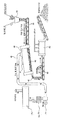
- FIG. 1 is a view showing the overall purification process of contaminated soil and gravel using a contaminated soil and gravel purification system according to an embodiment of the present invention.
- FIG. 2 is a view illustrating in detail a contaminant detachment unit in a contaminated soil and gravel purification system according to FIG. 1.
- FIG. 3 is a view showing in more detail the heat treatment in the contaminant desorption unit of the contaminated soil and gravel purification system according to FIG.
- FIG. 4 is a view showing in detail the principle of heat generation in the heat treatment unit in the contaminated soil and gravel purification system using the thermal desorption method according to the present invention.
- FIG. 5 is a view showing that the microwave absorption heating element provided on the outer circumferential surface of the inner cylinder in the contaminant desorption unit in the contaminated soil and gravel purification system according to FIG. 1 is wrapped with a heat insulating material.
- FIG. 6 is a process chart showing a contaminated soil and gravel purification method according to an embodiment of the present invention.
- FIG. 1 is a view showing a contaminated soil and gravel purification process using a contaminated soil and gravel purification system according to an embodiment of the present invention
- Figure 2 specifically showing the desorption of contaminants in the contaminated soil and gravel system according to Figure 1 3 is a view showing a heat treatment unit in a contaminant desorption unit of the contaminated soil and gravel purification system according to FIG. 1 in more detail.
- Transfer unit 30 for transferring the contaminated soil and gravel to the decontamination unit
- a contaminant desorbing unit 40 in which contaminants are thermally desorbed by heat of contaminated soil and gravel transferred from the conveying unit;
- recovery unit 50 for recovering the soil and gravel from which the contaminants have been removed via the contaminant desorption unit.
- the transfer unit 30 may be further provided with a drying means for drying the moisture in the contaminated soil and gravel, the drying means may be a known, common drying means such as heating, vent or hot air drying, etc. . As moisture is removed by the drying means, contaminant removal efficiency of contaminated soil and gravel by heat in the contaminant desorbing unit 40 may be increased.
- the contaminant desorption unit 40 serves as a resonance room for diffusely reflecting the microwaves irradiated from the microwave oscillation unit 41 in a sealed room structure except for the inlet and the outlet of the contaminated soil and gravel 42,
- the contaminated soil and the gravel 42 are transferred downward by the self-weight, or by the self-weight and vibration in a state in which the heat treatment part of the pollutant detachment part is inclined to one side.
- at least one microwave oscillation unit 41 is provided at one side of the outer cylinder, for example, the top or the side of the pollutant desorption unit, and the microwave oscillation unit 41 includes a microwave oscillator (magnetron) and a high voltage transformer.
- Furnaces include high voltage capacitors, high voltage diodes, and the like.
- the high voltage transformer converts a commercial AC voltage input from the outside into a high voltage suitable for high frequency generation (for example, about 4 kilovolts [kV]) and applies it to the magnetron, and the magnetron generates a high frequency by high voltage applied from the high voltage transformer To generate microwaves.
- Microwave frequency should use ISM (Industrial, Scientific and Medical) frequency, but it is preferable to use the 2,450MHz band mainly to take advantage of the smoothness of supply and demand, but is not limited to this, depending on the purpose of 300MHz ⁇ 300GHz Microwaves with frequency can be used in various modifications.
- a cooling fan is installed at one end of the magnetron to cool the high temperature generated by the magnetron, the cooling fan is connected to the fan motor, and when a voltage is applied to the fan motor from the outside, the fan motor is operated.
- the cooling fan is driven to blow external cold air to the magnetron, thereby cooling the high heat generated in the magnetron.
- a cooling fan may be excluded when an individual cooling device is not required, such as when using another device for cooling the magnetron or when exposed to the outside.
- the microwave oscillation portion 41 spaced apart from the contaminant desorption portion 40 can be connected using a waveguide (not shown).
- the pollutant desorption unit 40 may be further connected to the discharge after-treatment unit 70 for discharging the gas and dust discharged by the thermal desorption of the contaminants to be discharged.
- the exhaust gas and the dust are transported to the afterburner 71 through the transfer pipe 43, afterburned by the burner, and then cooled through the cooler 72 to be discharged to the atmosphere through the bag filter 73. Can be.
- the contaminants that are not dusted completely by the post-combustor as a dust state and are not preferable to be released into the atmosphere may be collected with a separate dust collector.
- Bonsai such as noxious gases, whose emissions to the atmosphere are also restricted, can be filtered by an adsorber to force suction and attachment to separate from the air.
- the recovery unit 50 is provided for recovering the soil and gravel (purified soil and gravel, 42-1) from which the contaminants have been removed via the contaminant desorbing unit 40.
- a cooling treatment unit 60 for treating and recovering the cooling water.
- FIG. 2 is a view specifically illustrating contaminant desorption part in the contaminated soil and gravel purification system according to FIG. 1, (a) a plan view, (b) a front cross-sectional view, and (c) a side view, and FIG. 3 is a contaminated soil and gravel according to FIG. 1. More specifically, the heat treatment unit is shown in the contaminant desorption unit of the purification system.
- the contaminated soil and the gravel 42 is the inlet 410 is injected, the contaminated soil and gravel heat-desorption treatment unit 420 and the thermal desorption treated soil and gravel discharge outlet 430 is configured to include
- the one side or the plurality of microwave oscillation portions 41 are connected to the heat treatment part 420, and an outer cylinder 421 constituting a cylindrical fixed container and a cylinder having a smaller diameter than the outer cylinder in the outer cylinder are provided with a rotating shaft ( 423 is rotatably installed in the outer cylinder 421 and is provided with an inner cylinder 422 into which contaminated soil and gravel are introduced through the inlet 410, and the rotating shaft 423 outside the outer cylinder 421.
- the extended driving motor 424 is provided, the outer peripheral surface of the inner cylinder 422 is provided with a microwave absorption heating element 426 for absorbing microwaves to generate heat, between the outer cylinder and the inner cylinder It is provided with a cavity space (427) for reflecting the microwaves, the microwaves emitted from the microwave oscillation unit 41 causes diffuse reflection in the cavity space (427), the microwave absorption heating element (426) provided on the outer peripheral surface of the inner cylinder (422) And heat desorption of contaminants on the surface of the contaminated soil and gravel 42 inside the inner cylinder by generating heat.
- the driving motor 424 is illustrated as a driving force is transmitted to the rotation shaft 423 by the chain 425, but the driving motor 424 is not necessarily to be thus performed, but may be transmitted in a geared manner. 424 may be directly connected.
- one side or one side of the microwave oscillation unit 41 is connected to one side of the heat treatment unit 420.
- the position is preferably at the top or side but may be installed at the bottom.
- the outer cylinder 421 and the outer cylinder 421 constituting the cylindrical fixed container is provided in the cylindrical having a smaller diameter than the outer cylinder and is rotatably installed in the outer cylinder 421 by the rotation shaft 423
- An inner cylinder 422 into which contaminated soil and gravel are introduced through an inlet 410 is provided, and a driving motor 424 is provided at an outer side of the outer cylinder 421 to which the rotation shaft 423 extends, and the inner cylinder
- the outer circumferential surface of the 422 is provided with a microwave absorption heating element 426 for absorbing microwaves to generate heat, and a cavity space 427 for reflecting the microwaves is provided between the outer cylinder and the inner cylinder is irradiated from the microwave oscillator 41
- the inner tube by generating reflected light in the cavity space 427 and generating heat in
- FIG 3 is a view showing the heat treatment unit in the contaminant desorption unit of the contaminated soil and gravel purification system according to Figure 1 in more detail
- Figure 4 is a heat generation in the heat treatment unit in the contaminated soil and gravel purification system using the thermal desorption method according to the present invention. It is a figure which showed the principle concretely.
- the method according to the present invention does not thermally desorb contaminated soil and gravel in the drum by using high heat generated from the contaminated soil and gravel in a heat source (torch), but heat generated from the microwave absorption heating element. Since the heat transferred indirectly into the inner cylinder and the heat transferred in direct contact with soil and gravel directly, the heat transfer efficiency is high, and the heat source works evenly throughout the inner cylinder, thereby enabling uniform heating as a whole, resulting in uniform thermal desorption. In addition, since the heat insulating material is formed on the outside of the microwave absorption heating element to prevent heat from being lost to the outside, the heat transfer efficiency to contaminated soil and gravel is further improved, thereby maximizing the heat desorption efficiency.
- the present invention is provided with a rod-shaped temperature measuring unit 428 at the center of the inner cylinder 422 can detect the temperature inside the inner cylinder.
- FIG. 5 is a view showing that the microwave absorption heating element provided on the outer circumferential surface of the inner cylinder in the contaminant desorption unit in the contaminated soil and gravel purification system according to FIG. 1 is wrapped with a heat insulating material.
- a microwave absorption heating element (not shown in FIG. 5) is provided on an outer circumferential surface of the inner cylinder 422 in a contaminant removal unit in a contaminated soil and gravel purification system according to the present invention, wherein the microwave absorption heating element is As a quenched steel slag particle having a particle size of 5.0 mm or less and a sphericity of 0.5 or more, the quenched steel slag particles may be fixed by being surrounded by an outer shell (for example, a heat resistant metal mesh) to be fixed to the inner circumferential surface of the inner cylinder.
- an outer shell for example, a heat resistant metal mesh
- the microwave absorption heating element is a hardened body that is cured by mixing a binder in a quenching steel slag particle having a particle size of 5.0 mm or less and a sphericity of 0.5 or more, and may be applied and fixed to the inner circumferential outer surface of a uniform thickness.
- the binder may be a mixture of cement and water, may be a dedicated adhesive, and in general, any binder capable of binding inorganic materials may be used.
- the outer circumferential surface of the microwave absorbing heating element is preferably surrounded by a heat insulator so that heat generated in the microwave absorbing heating element is concentrated in the inner direction instead of the outer direction.
- a heat insulator Glass wool, gypsum, heat-resistant plastic, heat-resistant ceramic, heat-resistant paper or stone powder may be used as the heat insulator that may be used in the present invention.
- the contaminated soil and gravel in the present invention has been described with reference to the soil and gravel of the railway site, but also should be interpreted to include both general soil and gravel that need to be decontaminated. It should also be interpreted to include both soil and gravel or both.
- the term "above” means that the value is higher than the corresponding value and generally has an upper limit that can be understood as common sense and reasonably understood in the field to which the present technology belongs. It means that it has a lower limit as much as can be commonly understood and reasonably understood in the field to which the present technology belongs, which should be understood as an expression for simple and clear representation of the invention.
- the heating element according to the present invention is a special ceramic composition, which is a ceramic composition which is a quenching steel slag having a particle size of 5.0 mm or less and a spherical ratio of 0.5 or more.
- the quenched steel slag is more preferably a particle size of 3.0mm or less, even more preferably 1.0mm or less.
- the slag discharged from the steelmaking factory is treated by receiving the slag in the slag port disposed in the lower part of the converter or the electric furnace and then discharging it to the treatment plant.
- the slag is cooled by spraying a large amount of water on the discharged slag.
- the iron component in the slag was selected through a magnetic separator and used again as an iron source.
- the remaining slag had no special use, so it was mostly used as landfill or aggregate for road pavement.
- landfill cost is incurred additionally, and if the landfill volume is large, the cost is considerably burdened and environmental problems occur. Therefore, it is urgent to develop a solution for separate use. .
- the steelmaking slag cooled by the cooling is called slow cooling steelmaking slag, which contains a large amount of free lime (free CaO), and the free lime reacts with water in road pavement to produce calcium hydroxide (Ca (OH)). 2 ) form.
- the formed calcium hydroxide has a larger volume and easier to differentiate than free lime, so when used as a roadbed material, there is a problem that the road is lifted, and the differentiated calcium hydroxide causes air and water pollution.
- calcium hydroxide is alkaline, which may cause soil contamination, the use of aggregates for road pavement was also very limited.
- the quenched steel slag may be manufactured by a method of dropping hot molten slag and spraying high speed airflow to blow off high temperature molten slag to rapidly cool the high speed airflow and to produce fine powder.
- the slag of fine powder rather than the slag of the bulk is produced, thus eliminating the need for a separate crushing process and reducing the amount of free lime.
- the conventional quenching steel slag was focused on reducing the amount of free lime and using it as a construction aggregate.
- the present invention is to develop a new solution of such quenched steel slag, and to find the property that the quenched steel slag absorbs microwaves to generate heat, and use it as a heating material.
- the quenching steel slag used in the present invention is not to use conventional quenching steel slag conventionally used as it is, but is manufactured and used in a purified form using a special screening and purification method.
- an example of a method for manufacturing a quenched steel slag according to the present invention is as follows. That is, in the first step, the quenching steel slag having a particle size of 5.0 mm or less is subjected to sieving process, and in the second step, a magnetic separator having a magnetic strength of 500 gauss or more, preferably 700 to 5,000 gauss, is used. After screening and screening only particles having a microwave absorption efficiency required by the present invention, only screens with a sphericity of 0.5 or more are screened through a spherical screening device.
- the sieving process, the spherical screening process and the magnetic screening process may be changed in order or proceed simultaneously, all of which fall within the scope of the present invention.
- the quenched steel slag obtained through such a special screening and purification operation is simply referred to as "MIP (Microwave-irradiated pyrogen)".
- the particle size of the quenched steel slag is preferably 5.0 mm or less, and the sphericity is required to be 0.5 or more.
- the spherical ratio means the ratio of the smallest diameter to the longest diameter of the particle as a shape factor. If the quenching steel slag has a spherical ratio of less than 0.5, it has a crushed shape and thus the point where the microwave is sharp.
- the quenched steel slag has the characteristics of an intermediate semiconductor between the conductor and the non-conductor, absorption heating and induction heating are performed, and internal microwaves are transmitted according to the state of charge. That is, when microwave is applied to the continuous spherical quenching steel slag, the microwave is transmitted along the quenching steel slag by the surface effect, and the absorption and induction heating are also performed in the adjacent quenching steel slag as before.
- the microwave absorption heating element is a quenched steel slag particles having a particle size of 5.0 mm or less and a spherical ratio of 0.5 or more, so that the quenched steel slag particles are surrounded by an outer surface of a metal mesh, a fiber network, or the like so as to be fixed to an inner circumferential surface of the inner cylinder. can do.
- the microwave absorbing heating element may be a cured body obtained by mixing a binder and curing the quenching steel slag particles having a particle size of 5.0 mm or less and a spherical ratio of 0.5 or more.
- the binder may be a mixture of cement and water, or a dedicated adhesive.
- the microwave absorption heating element has been described with reference to “MIP” described above, but is not necessarily limited thereto, and materials known as conventional microwave absorption heating elements, specifically, SiC, ZrO 2 , SiN 4 , Of course, carbon and the like can be used alone, mixed or mixed with the MIP, which is also included in the scope of the present invention.
- the outer cylinder inner circumferential surface of the contaminant detachment part 40 may further include a reflector to effectively reflect microwaves.
- the material used as the reflecting plate is preferably a material that does not absorb microwaves, and examples thereof include steel, aluminum, or copper.
- the reflecting plate has a smooth plate shape or a plate shape irregularities on the surface.
- the present invention also includes a method for purifying contaminated soil and gravel using a contaminated soil and gravel thermal desorption system by microwave indirect irradiation having the above characteristics.
- FIG. 6 is a process chart showing a contaminated soil and gravel purification method according to an embodiment of the present invention.
- the contaminant desorption unit is configured to include an inlet for the contaminated soil and gravel input, a heat treatment unit for heat desorption of the contaminated soil and gravel and a discharge port for discharging the thermal desorption treated soil and gravel, the one side of the heat treatment unit
- the microwave oscillation unit is connected to a singular or plural, the outer cylinder constituting the cylindrical fixed container and the inner cylinder is provided with a cylindrical diameter smaller than the outer cylinder and the inner cylinder rotatably installed in the outer cylinder by a rotating shaft, The outside of the outer cylinder is connected to the drive motor extending the rotation axis, the outer peripheral surface of the inner cylinder is provided with a microwave absorption heating element for generating heat, the cavity space between the outer cylinder and the inner cylinder is provided with a reflection of the microwave In the microwave oscillation unit
- the microwave is a configuration causes a diffuse reflection in the cavity so as to thermal desorption of contaminants in contaminated
- the contaminated soil and gravel thermal desorption system by the microwave indirect irradiation method according to the present invention and the contaminated soil and gravel thermal desorption method using the same have been described.
- the new contaminated soil and gravel purification device and method of the present invention since the purification operation can be completed by only treating the contaminated soil and the gravel once, it is possible to secure high productivity and waste materials discharged from the steelmaking process. Since it is used as a raw material of the heating element particles can achieve the object even without using a conventional expensive material, it is possible to secure a high economic efficiency can significantly increase the applicability of the actual site.
Landscapes
- Engineering & Computer Science (AREA)
- Life Sciences & Earth Sciences (AREA)
- Microbiology (AREA)
- Physics & Mathematics (AREA)
- Biotechnology (AREA)
- Biomedical Technology (AREA)
- Health & Medical Sciences (AREA)
- Electromagnetism (AREA)
- Molecular Biology (AREA)
- Mechanical Engineering (AREA)
- General Engineering & Computer Science (AREA)
- Thermal Sciences (AREA)
- Soil Sciences (AREA)
- Environmental & Geological Engineering (AREA)
- Processing Of Solid Wastes (AREA)
Abstract
본 발명은 마이크로파 간접 조사 방식에 의한 오염 토양 및 자갈 열탈착 시스템 및 이를 이용한 오염 토양 및 자갈 열탈착 방법에 관한 것으로서, 더욱 상세하게는 각종 유류나 유기 폐기물 등의 오염원에 의해 오염된 토양 및 자갈을 마이크로파 간접 조사 방식을 이용하여 경제적으로 정화할 수 있는 장치 및 그 방법을 제공한다. 본 발명에 사용되는 마이크로파 간접 조사 방식에 의한 오염 토양 및 자갈 열탈착 시스템은 오염물질이 열탈착되는 오염물 탈착부의 구조를 개선하여 외통과 내통으로 구성하고 내통 내부로 오염 토양 및 자갈이 지나가도록 구성하며 내통의 외주면에 마이크로파 흡수 발열체를 구비하여 상기 마이크로파 흡수 발열체에 마이크로파를 조사함으로써 내통 내부의 오염 토양 및 자갈의 오염물질이 열탈착될 수 있도록 할 수 있으며 마이크로파 흡수 발열체로서 원가가 비교적 저렴한 동시에 열발생 효율이 우수한 재료를 사용함으로써 경제성을 확보하는 동시에 저온 및 고온의 열 발생이 이루어지도록 하여 유류의 종류에 상관없이 충분한 열탈착이 가능하도록 함으로써 실제 현장 활용 가능성을 높일 수 있다.
Description
본 발명은 마이크로파 간접 조사 방식에 의한 오염 토양 및 자갈 열탈착 시스템 및 이를 이용한 오염 토양 및 자갈 열탈착 방법에 관한 것으로서, 더욱 상세하게는 각종 유류나 유기 폐기물 등의 오염원에 의해 오염된 토양 및 자갈을 마이크로파 간접 조사 방식을 이용하여 경제적으로 정화할 수 있는 장치 및 그 방법에 관한 것이다.
최근 지구 환경과 인간의 생활 환경에 대한 관심이 높아지고 환경 오염에 따른 폐해가 인식되면서 전세계적으로 환경 오염 복원 사업이 실시됨에 따라 복원 사업 시장이 급성장하고 있다.
환경 복원은 자발적이기보다는 정부의 규제와 조정에 의해 실행되는 것이 일반적이며, 인간 건강과 환경 보호를 위한 환경법과 규제의 도입이 환경 복원 산업을 움직이는 원동력이 된다.
최근, 철도 부지에 대한 복원 사업이 활발하게 이루어지면서 토양뿐만 아니라 도상 자갈에 대한 복원 기술에 대한 관심도 크게 증가하고 있다. 이는 최근 토양환경보전법이 강화됨에 따라 철도 부지의 오염 토양 및 자갈에 대한 규제가 구체화됨에 따른 결과이기도 하다.
철도 부지의 토양과 도상 자갈의 주요 오염원은 지하나 지상에 위치한 유류 저장 탱크 및 기관차 급유 지역에서의 유류 유출, 철도 차량에서 발생하는 연료, 그리스, 윤활유 등의 누유와 낙유, 폐기물 적환장에서 배출되는 침출수, 차량의 정비 시에 발생하는 낙유 및 작업 시에 발생하는 각종 입자상 물질 등으로 그 오염원이 매우 다양하고 광범위하다. 이러한 철도 토양 및 자갈 오염의 확산 방지를 위하여, 일부 사업장에서는 디젤 기관차의 낙유 개소 정비, 철도 차량 정치장에 대한 롤패드 설치와 FRP 또는 철판 설치, 철도 차량 입출고선의 콘크리트 포장 등을 시행하고 있으나 이는 궁극적인 해결 방법이 아니라 임시 방편에 불과하다. 철도 작업장 및 오염 유발 시설물은 밀집해 있지 않고 넓은 지역에 분포되어 있으며, 철도 부지의 오염에 대한 기초 자료가 부족하여 오염도의 파악과 오염원의 관리 및 제어에 많은 어려움이 있기 때문에 철도의 토양 및 자갈 오염 문제를 해결하는 데에는 많은 시간과 비용이 소요되는 것이 현실이다.
한편, 현재 국내외 철도 노선의 상당 구간에는 도상 자갈이 사용되고 있는데, 철도용 도상 자갈은 선로의 가장 상부에 부설되기 때문에 가장 먼저 오염이 된다. 특히 철도 분기기의 경우에는 상당량의 윤활유가 사용되어 도상 자갈을 오염시킨다. 이러한 도상 자갈 표면의 오염 물질은 중력 또는 우수 등에 의하여 지속적으로 선로 하단부로 이동하여 노반 및 노반 하부의 토양을 오염시킨다. 또한 토양 주위를 흐르는 지하수가 오염되면 주변 토양도 오염되어 점차 오염 지역이 확대된다.
현재 오염된 철도 도상 자갈의 교체 작업 중에 수거된 오염 자갈은 매립 형태로 폐기되고 있다. 이 때 수거된 철도 도상 자갈은 대부분 표면이 심하게 오염되어 있기 때문에 일반 폐기물이 아니라 지정 폐기물로 지정되어 매립되고 있다. 그러나, 매립된 오염 물질은 침출수, 매립 가스, 악취 등의 형태로 계속해서 장기적으로 환경에 악영향을 미치게 되므로 매립보다는 오염 물질의 분리 및 처리가 필요하다.
점차 매립장 부족 현상이 심화되고 있으며, 이에 따라 매립 비용 단가도 지속적으로 상승하고 있기 때문에 매립이 아닌 다른 처리 방법의 필요성이 더욱 커지고 있다. 아울러 도상 자갈의 교체를 위해서는 신자갈이 필요한데, 신자갈의 확보를 위해서 산림 및 생태계 파괴가 계속되고 있으나, 정부의 산림 파괴 관련 규제 강화와 환경 단체 및 국민들의 생태계 파괴에 대한 반대 여론 등으로 인하여 신자갈의 수급 또한 점차 어려워지고 있기 때문에 도상 자갈의 재활용 필요성이 더욱 대두되고 있는 상황이다.
또한, 상기한 철도 도상 자갈 뿐만 아니라 유류나 유기물 등에 의해 오염된 타 지역의 자갈도 현재는 대부분 매립되고 있는 실정이므로 이를 정화하여 재사용할 필요가 큰 상황이다.
현재, 도상 자갈 등 오염된 자갈을 정화 처리하는 기술로서, 열을 이용하여 오염물질을 분해 및 무해화시키는 열적 처리 방법, 토양 세균을 활성화시키거나 특별히 개발된 세균 균주를 토입하여 유기화합물의 생분해를 촉진하는 미생물학적 처리 방법, 오염된 토양이나 자갈 내의 공극을 통해 오염 공기를 뽑아내어 처리하는 토양내 통풍법(in-situ venting, ISV) 또는 토양증기 추출법(soil vapor extraction, SVE) 등과 같은 증기 추출 기술 등이 개발되어 활용되고 있으나 경제성과 효율성이 떨어지기 때문에 적용 범위가 확대되는 데는 한계가 있다.
한편, 기 제안된 특허(대한민국 등록특허 제10-0614612호)에서는 선로 위를 주행할 수 있는 차량 내에 도상 자갈을 채취할 수 있는 설비와 채취된 도상 자갈에 모래 등의 미디어를 이용하여 블라스팅을 실시함에 의해 도상 자갈 표면의 오염물질을 제거하고, 오염 물질이 제거된 자갈을 다시 선로에 살포하는 설비를 갖춤으로써 선로를 따라 이동해가며 도상 자갈의 오염물질을 제거하여 재활용할 수 있는 기술을 제안한 바 있다. 그러나 위 방법은 선로에서 이동식으로 도상 자갈의 정화가 가능하다는 장점은 있으나 블라스팅 방법을 사용하므로 오염 제거 효율이 높지 않기 때문에 경제성과 효율성이 미흡하므로 실제 현장에서 활용되기는 쉽지 않은 기술이다.
본 발명은 상기와 같은 종래 기술의 상황을 고려하여 새로이 개발된 것으로서, 마이크로파를 이용한 열탈착법에 의해 오염된 토양 및 자갈로부터 오염물질이 열탈착되는 오염물 탈착부의 구조를 개선하여 외통과 내통으로 구성하고 내통 내부로 오염된 토양 및 자갈이 지나가도록 구성하며 내통의 외주면에 마이크로파 흡수 발열체를 구비하여 상기 마이크로파 흡수 발열체에 마이크로파를 조사함으로써 내통 내 오염된 토양 및 자갈 표면의 오염물질이 열탈착될 수 있도록 하며 마이크로파 흡수 발열체로서 기존 물질의 가격에 비해 매우 저렴한 동시에 열발생 효율이 우수한 재료를 사용함으로써 경제성을 확보하는 동시에 저온 및 고온의 열 발생이 이루어지도록 하여 유류의 종류에 상관없이 단 1회의 통과만으로도 충분한 열탈착이 가능하도록 함으로써 실제 현장 활용 가능성을 높인 새로운 개념의 마이크로파를 이용한 오염 토양 및 자갈 정화 장치 및 그 방법을 제공하고자 한다.
상기 과제를 달성하기 위하여 본 발명은
오염 토양 및 자갈을 오염물 탈착부로 이송하기 위한 이송부;
상기 이송부에서 이송되는 오염 토양 및 자갈이 열에 의해 오염물이 열탈착되는 오염물 탈착부로서, 상기 오염 토양 및 자갈이 투입되는 투입구, 상기 오염 토양 및 자갈이 열탈착 처리되는 열처리부 및 열탈착 처리된 토양 및 자갈이 배출되는 배출구를 포함하여 구성되며, 상기 열처리부 일측에는 마이크로파 발진부가 단수 또는 복수로 연결되고, 원통형의 고정된 컨테이너를 구성하는 외통 및 상기 외통 내에 상기 외통보다 직경이 작은 원통형으로 구비되며 회전축에 의해 상기 외통 내에서 회전 가능하게 설치되고 상기 투입구를 통해 오염 토양 및 자갈이 투입되는 내통이 구비되며, 상기 외통 외부에는 상기 회전축이 연장되어 연결되는 구동모터가 구비되고, 상기 내통의 외주면에는 마이크로파를 흡수하여 열을 발생시키는 마이크로파 흡수 발열체가 구비되며, 상기 외통 및 내통 사이에는 마이크로파가 반사되기 위한 캐비티 공간이 구비되어 상기 마이크로파 발진부에서 조사된 마이크로파가 상기 캐비티 공간에서 난반사를 일으켜 상기 내통의 외주면에 구비된 마이크로파 흡수 발열체에서 열을 발생시킴에 의해 상기 내통 내부의 오염 토양 및 자갈 표면의 오염물을 열탈착시키도록 구성된 오염물 탈착부; 및
상기 오염물 탈착부를 거쳐 오염물이 제거된 토양 및 자갈을 회수하는 회수부;를 포함하여 구성되는 것을 특징으로 하는 마이크로파 간접 조사 방식에 의한 오염 토양 및 자갈 열탈착 시스템을 제공한다.
본 발명의 일 실시예에서, 상기 오염물 탈착부에는 오염물 탈착에 의해 배출되는 가스와 분진을 이송하여 처리한 후 방출하기 위한 배출물 후처리부가 연결되는 것을 특징으로 한다.
본 발명의 일 실시예에서, 상기 마이크로파 흡수 발열체는 입자크기 5.0 mm 이하이고 구형률이 0.5 이상인 급냉 제강슬래그 입자로서 상기 급냉 제강슬래그 입자가 내통 외주면에 고정되도록 외피에 의해 둘러싸여 고정되는 것을 특징으로 한다.
본 발명의 일 실시예에서, 상기 마이크로파 흡수 발열체는 입자크기 5.0 mm 이하이고 구형률이 0.5 이상인 급냉 제강슬래그 입자에 바인더를 혼합하여 경화시킨 경화체로서 상기 내통 외주면에 균일 두께로 도포되어 고정되는 것을 특징으로 한다.
본 발명의 일 실시예에서, 상기 마이크로파 흡수 발열체의 외주면은 단열재로 둘러싸인 것을 특징으로 한다.
또한, 상기 과제를 달성하기 위하여 본 발명은
(1) 오염 토양 및 자갈을 오염물 탈착부로 이송하는 단계;
(2) 상기 이송되는 오염 토양 및 자갈을 이송하여 오염물 탈착부에서 열에 의해 오염물을 탈착하는 단계로서, 상기 오염물 탈착부는 상기 오염 토양 및 자갈이 투입되는 투입구, 상기 오염 토양 및 자갈이 열탈착 처리되는 열처리부 및 열탈착 처리된 토양 및 자갈이 배출되는 배출구를 포함하여 구성되며, 상기 열처리부 일측에는 마이크로파 발진부가 단수 또는 복수로 연결되고, 원통형의 고정된 컨테이너를 구성하는 외통 및 상기 외통 내에 상기 외통보다 직경이 작은 원통형으로 구비되며 회전축에 의해 상기 외통 내에서 회전 가능하게 설치되고 상기 투입구를 통해 오염 토양 및 자갈이 투입되는 내통이 구비되며, 상기 외통 외부에는 상기 회전축이 연장되어 연결되는 구동모터가 구비되고, 상기 내통의 외주면에는 마이크로파를 흡수하여 열을 발생시키는 마이크로파 흡수 발열체가 구비되며, 상기 외통 및 내통 사이에는 마이크로파가 반사되기 위한 캐비티 공간이 구비되어 상기 마이크로파 발진부에서 조사된 마이크로파가 상기 캐비티 공간에서 난반사를 일으켜 상기 내통의 외주면에 구비된 마이크로파 흡수 발열체에서 열을 발생시킴에 의해 상기 내통 내부의 오염 토양 및 자갈 표면의 오염물을 열탈착시키는 단계; 및
(3) 상기 오염물 탈착부를 거쳐 오염물이 제거된 토양 및 자갈을 회수하는 단계;를 포함하여 구성되는 것을 특징으로 하는 마이크로파 간접 조사 방식에 의한 오염 토양 및 자갈 열탈착 방법을 제공한다.
본 발명에 따른 마이크로파 간접 조사 방식에 의한 오염 토양 및 자갈 열탈착 시스템 및 이를 이용한 오염 토양 및 자갈 열탈착 방법의 특징 및 장점을 설명하면 다음과 같다.
1. 우선, 열에 의한 오염물 탈착 방법을 사용하므로 오염원에 관계없이 오염 물질의 제거가 가능하며 특히 유류 관련 오염 물질의 제거에 탁월한 효과가 있다.
2. 또한, 기존의 마이크로파를 이용한 열탈착 방법에 사용되는 판상 또는 스틱형의 발열체와 같은 장치를 별도로 제조 장착할 필요가 없으므로 설비 제작 비용이 저렴하다.
3. 또한, 외통 및 내통으로 구성된 오염물 탈착부를 이용하고 정화 대상물(오염 토양 및 자갈)을 내부에서 회전하는 내통에 투입하며 상기 내통 외주면에 마이크로파 흡수 발열체를 구비하여 상기 마이크로파 흡수 발열체에 마이크로파를 조사함으로써 간접 방식에 의해 오염된 토양 및 자갈에 열이 전달되도록 함에 의해 오염물질을 열탈착시키게 되므로 열탈착 효율이 기존의 방법보다 현저히 높다. 따라서 충분한 오염물질 제거 성능을 발휘하여 기존 방법에 비해 생산성이 현저히 높다.
4. 또한, 마이크로파 흡수 발열체로서 사용되는 재료가 종래 기술의 고가의 재료에 비해 현저히 저렴한 재료를 사용하므로 경제성이 뛰어나다. 즉, 종래 기술에서 사용되는 탄화규소(SiC)의 경우 시중가가 650만원/톤 정도이고, 지르코니아(ZrO2)의 경우에도 시중가가 220만원/톤 정도로 매우 고가이나, 본 발명에 따른 마이크로파 흡수 발열체는 제조비를 모두 포함할 경우에도 20만원/톤을 넘지 않는다. 따라서 경제성으로 인해 활용이 되지 않던 종래 기술에 비해 본 기술은 경제성을 확보할 수 있어 실제 현장 적용 가능성이 매우 높다.
5. 또한, 마이크로파 흡수체가 종래 방식처럼 폐기하거나 그물망 등을 이용해 걸러내는 것이 아니라 마이크로파 흡수 발열체가 내통에 구비되어 반영구적으로 사용될 수 있으므로 별도의 후공정이 필요없고 공정 운용 비용이 현저히 감소될 수 있는 장점이 있다.
도 1은 본 발명의 일 실시예에 따른 오염 토양 및 자갈 정화 시스템을 이용한 오염 토양 및 자갈의 정화 과정을 전체적으로 나타낸 도면이다.
도 2는 도 1에 따른 오염 토양 및 자갈 정화 시스템에서 오염물 탈착부를 구체적으로 나타낸 도면이다.
도 3은 도 1에 따른 오염 토양 및 자갈 정화 시스템의 오염물 탈착부에서 열처리부를 더욱 구체적으로 나타낸 도면이다.
도 4는 본 발명에 따른 열탈착 방법을 이용한 오염 토양 및 자갈 정화 시스템 중에서 열처리부에서의 발열 원리를 구체적으로 나타낸 도면이다.
도 5는 도 1에 따른 오염 토양 및 자갈 정화 시스템에서 오염물 탈착부에 있어서 내통 외주면에 구비된 마이크로파 흡수 발열체가 단열재에 의해 감싸진 것을 나타내는 도면이다.
도 6은 본 발명의 일 실시예에 따른 오염 토양 및 자갈 정화 방법을 나타낸 공정도이다.
이하에서는 본 발명의 바람직한 실시예를 도면을 참조하여 상세하게 설명한다. 다만 이는 본 발명이 속하는 기술 분야에서 통상의 기술자가 본 발명을 용이하게 이해하고 실시할 수 있도록 설명하는 것일 뿐이고 본 발명의 범위가 하기 실시예의 범위로 한정되는 것으로 해석되어서는 안 된다.
도 1은 본 발명의 일 실시예에 따른 오염 토양 및 자갈 정화 시스템을 이용한 오염 토양 및 자갈 정화 과정을 전체적으로 나타낸 도면이고, 도 2는 도 1에 따른 오염 토양 및 자갈 시스템에서 오염물 탈착부를 구체적으로 나타낸 도면이며, 도 3은 도 1에 따른 오염 토양 및 자갈 정화 시스템의 오염물 탈착부에서 열처리부를 더욱 구체적으로 나타낸 도면이다.
도 1 내지 도 3을 참조하면, 본 발명에 따른 마이크로파 간접 조사 방식에 의한 오염 토양 및 자갈 열탈착 시스템은
오염 토양 및 자갈을 오염물 탈착부로 이송하기 위한 이송부(30);
상기 이송부에서 이송되는 오염 토양 및 자갈이 열에 의해 오염물이 열탈착되는 오염물 탈착부(40); 및
상기 오염물 탈착부를 거쳐 오염물이 제거된 토양 및 자갈을 회수하는 회수부(50);를 포함하여 구성된다.
먼저, 철도 등에서 오염된 토양 및 자갈은 컨베이어 벨트 등의 이송부(30)를 통해 오염물 탈착부(40)로 이송된다. 또한, 상기 이송부(30)에는 오염 토양 및 자갈에서 수분을 건조하기 위한 건조 수단이 추가로 구비될 수 있으며, 상기 건조 수단은 가열, 환풍 또는 열풍 건조 등과 같은 공지, 공용의 건조 수단이 적용될 수 있다. 이러한 건조 수단에 의해 수분이 제거됨으로써 오염물 탈착부(40)에서의 열기에 의한 오염 토양 및 자갈의 오염물 제거 효율이 증가할 수 있다.
상기 오염물 탈착부(40)는 오염 토양 및 자갈(42)이 들어오는 입구와 배출되는 출구를 제외하고는 밀폐된 룸 구조를 이루어 마이크로파 발진부(41)에서 조사되는 마이크로파를 난반사시키는 공진룸 역할을 하며, 상기 오염물 탈착부의 열처리부가 한쪽으로 기울어진 상태로 자중에 의해, 또는 자중과 진동에 의해 아래쪽 방향으로 상기 오염 토양 및 자갈(42)이 이송된다. 이 때 상기 오염물 탈착부의 외통 일측, 예를 들어 상부 또는 측부에는 마이크로파 발진부(41)가 1개 이상 구비되며, 상기 마이크로파 발진부(41)는 마이크로파 발진기(마그네트론)와 고전압변압기를 포함하여 구성되고, 추가로 고전압 콘덴서, 고전압 다이오드 등을 포함한다. 상기 고전압변압기는 외부로부터 입력되는 상용교류전압을 고주파 발생에 적합한 고전압(예를 들면, 4 킬로볼트[kV] 정도)으로 변압하여 마그네트론으로 인가하며, 마그네트론은 고전압변압기로부터 인가되는 고전압에 의하여 고주파발진을 하여 마이크로파를 발생시킨다. 마이크로파 주파수는 ISM(Industrial, Scientific and Medical) 주파수를 사용하되, 부품 수급의 원활성 등 장점을 살려 주로 2,450MHz대역을 사용하는 것이 바람직하나, 이에 한정하는 것은 아니고, 용도에 따라 300MHz ~ 300GHz 영역의 주파수를 갖는 마이크로파를 다양하게 변형하여 사용할 수 있다. 상기 마그네트론이 구동될 때 마그네트론에서 발생되는 고열을 냉각시키기 위해 마그네트론의 일단에는 냉각팬이 설치되고, 냉각팬은 팬모터와 연결되며, 외부로부터 전압이 팬모터에 인가되면 팬모터가 가동되면서 팬모터에 의해 냉각팬이 구동되어 외부의 찬공기를 마그네트론에 송풍함으로써, 마그네트론에서 발생되는 고열을 냉각시킬 수 있다. 다만, 경우에 따라 마그네트론의 냉각을 위한 다른 장치를 사용할 경우나 외부에 노출되는 경우와 같이 개별 냉각 장치가 필요 없을 경우에는 냉각팬을 제외할 수 있다. 또한, 상기 마이크로파 발진부(41)를 상기 오염물 탈착부(40)에서 이격되게 설치할 필요가 있는 경우에는 도파관(미도시)을 이용하여 연결할 수 있다.
상기 오염물 탈착부(40)에는 오염물의 열탈착에 의해 배출되는 가스와 분진을 이송하여 처리한 후 방출하기 위한 배출물 후처리부(70)가 추가로 연결될 수 있다. 상기 배출 가스와 분진은 이송관(43)을 통해 후연소기(71)로 이송된 후 버너에 의해 후연소되고, 이어서 냉각기(72)를 통해 냉각된 후 백필터(73)를 거쳐 대기 중에 방출될 수 있다. 이 때 분진 상태로서 후연소기에 의해 완전 연소되지 않고 대기 중에 방출되는 것이 바람직하지 않은 오염 물질은 별도의 집진 설비를 갖추어 수집될 수 있다. 또한 대기로의 배출이 제한되는 유해 가스와 같은 분재는 강제로 흡입 및 부착시켜 공기로부터 분리하기 위한 흡착기에 의해 걸러질 수 있다.
상기 오염물 탈착부(40)를 거쳐 오염물이 제거된 토양 및 자갈(정화 토양 및 자갈, 42-1)을 회수하기 위한 회수부(50)가 구비된다.
이어서 상기 회수부에서 회수된 토양 및 자갈은 고온 상태이므로 냉각수를 처리하여 회수하기 위한 냉각 처리부(60)가 추가로 포함하는 것이 바람직하다.
도 2는 도 1에 따른 오염 토양 및 자갈 정화 시스템에서 오염물 탈착부를 구체적으로 나타낸 도면으로 (a)평면도, (b)정단면도 및 (c)측면도이고, 도 3은 도 1에 따른 오염 토양 및 자갈 정화 시스템의 오염물 탈착부에서 열처리부를 더욱 구체적으로 나타낸 도면이다.
도 2 및 도 3을 참조하여 본 발명에 따른 오염 토양 및 자갈 정화 시스템의 오염물 탈착부(40)를 더욱 구체적으로 설명하면 다음과 같다.
상기 오염된 토양 및 자갈(42)이 투입되는 투입구(410), 상기 오염 토양 및 자갈이 열탈착 처리되는 열처리부(420) 및 열탈착 처리된 토양 및 자갈이 배출되는 배출구(430)를 포함하여 구성되며, 상기 열처리부(420) 일측에는 마이크로파 발진부(41)가 단수 또는 복수로 연결되고, 원통형의 고정된 컨테이너를 구성하는 외통(421) 및 상기 외통 내에 상기 외통보다 직경이 작은 원통형으로 구비되며 회전축(423)에 의해 상기 외통(421) 내에서 회전 가능하게 설치되고 상기 투입구(410)를 통해 오염 토양 및 자갈이 투입되는 내통(422)이 구비되며, 상기 외통(421) 외부에는 상기 회전축(423)이 연장되어 연결되는 구동모터(424)가 구비되고, 상기 내통(422)의 외주면에는 마이크로파를 흡수하여 열을 발생시키는 마이크로파 흡수 발열체(426)가 구비되며, 상기 외통 및 내통 사이에는 마이크로파가 반사되기 위한 캐비티 공간(427)이 구비되어 상기 마이크로파 발진부(41)에서 조사된 마이크로파가 상기 캐비티 공간(427)에서 난반사를 일으켜 상기 내통(422)의 외주면에 구비된 마이크로파 흡수 발열체(426)에서 열을 발생시킴에 의해 상기 내통 내부의 오염 토양 및 자갈(42) 표면의 오염물을 열탈착시키도록 구성된다.
도 2에서는 구동모터(424)가 체인(425)에 의해 회전축(423)에 구동력이 전달되는 것으로 도시되었으나 반드시 이와 같이 되어야 하는 것은 아니고 기어 방식으로 전달되도록 할 수도 있으며, 회전축(423)에 구동모터(424)가 직접 연결되도록 할 수도 있다.
도 2를 참조하면, 상기 열처리부420) 일측에는 마이크로파 발진부(41)가 단수 또는 복수로 연결되는데, 그 위치는 상부 또는 측부가 바람직하나 하부에 설치되는 것도 가능하다. 또한, 원통형의 고정된 컨테이너를 구성하는 외통(421) 및 상기 외통(421) 내에 상기 외통보다 직경이 작은 원통형으로 구비되고 회전축(423)에 의해 상기 외통(421) 내에서 회전 가능하게 설치되며 상기 투입구(410)를 통해 오염 토양 및 자갈이 투입되는 내통(422)이 구비되며, 상기 외통(421) 외부에는 상기 회전축(423)이 연장되어 연결되는 구동모터(424)가 구비되고, 상기 내통(422)의 외주면에는 마이크로파를 흡수하여 열을 발생시키는 마이크로파 흡수 발열체(426)가 구비되며, 상기 외통 및 내통 사이에는 마이크로파가 반사되기 위한 캐비티 공간(427)이 구비되어 상기 마이크로파 발진부(41)에서 조사된 마이크로파가 상기 캐비티 공간(427)에서 난반사를 일으켜 상기 내통(422)의 외주면에 구비된 마이크로파 흡수 발열체(426)에서 열을 발생시킴에 의해 상기 내통 내부의 오염 토양 및 자갈 표면의 오염물을 열탈착시키도록 구성된다.
도 3은 도 1에 따른 오염 토양 및 자갈 정화 시스템의 오염물 탈착부에서 열처리부를 더욱 구체적으로 나타낸 도면이고, 도 4는 본 발명에 따른 열탈착 방법을 이용한 오염 토양 및 자갈 정화 시스템 중에서 열처리부에서의 발열 원리를 구체적으로 나타낸 도면이다.
도 3 및 도 4를 참조하면, 본 발명에 따른 방법은 오염 토양 및 자갈을 열원(토치)에서 발생하는 고열을 이용하여 드럼 내의 오염 토양 및 자갈을 열탈착시키는 것이 아니라, 마이크로파 흡수 발열체에서 발생하는 열이 내통 내로 간접적으로 전달되고 이렇게 전달된 열이 직접 오염 토양 및 자갈과 접촉하기 때문에 열전달 효율이 높고 열원이 내통 전체적으로 고르게 작용하므로 전체적으로 균일한 가열이 가능하게 되어 균일한 열탈착이 이루어지는 장점이 있다. 또한, 단열재는 마이크로파 흡수 발열체의 외부에 형성되어 열이 외측으로 손실되는 것을 방지하기 때문에 오염 토양 및 자갈에 대한 열전달 효율이 더욱 향상되어 열탈착 효율을 극대화시킬 수 있는 것이다.
또한, 본 발명에서 내통(422)의 중심에는 봉 형상의 온도측정부(428)를 구비하여 내통 내부의 온도를 검측할 수 있다.
도 5는 도 1에 따른 오염 토양 및 자갈 정화 시스템에서 오염물 탈착부에 있어서 내통 외주면에 구비된 마이크로파 흡수 발열체가 단열재에 의해 감싸진 것을 나타내는 도면이다.
도 5를 참조하면, 본 발명에 따른 오염 토양 및 자갈 정화 시스템에서 오염물 탈착부에 있어서 내통(422) 외주면에는 마이크로파 흡수 발열체(도 5에는 미도시됨)가 구비되는데, 이 때 상기 마이크로파 흡수 발열체는 입자크기 5.0 mm 이하이고 구형률이 0.5 이상인 급냉 제강슬래그 입자로서 상기 급냉 제강슬래그 입자가 내통 외주면에 고정되도록 외피(예를 들어 내열성 금속 망체)에 의해 둘러싸여 고정되도록 할 수 있다.
또한, 상기 마이크로파 흡수 발열체는 입자크기 5.0 mm 이하이고 구형률이 0.5 이상인 급냉 제강슬래그 입자에 바인더를 혼합하여 경화시킨 경화체로서 상기 내통 외주면에 균일 두께로 도포되어 고정될 수도 있다. 본 발명에서 상기 바인더는 시멘트와 물의 혼합물일 수 있고, 전용 접착제일 수도 있으며, 기타 일반적으로 무기물을 결합시킬 수 있는 바인더는 모두 사용될 수 있다.
또한, 도 5에 도시된 바와 같이, 상기 마이크로파 흡수 발열체의 외주면은 단열재로 둘러싸서 상기 마이크로파 흡수 발열체에서 발생한 열이 외측 방향이 아니라 내측 방향으로 집중적으로 전달되도록 하는 것이 바람직하다. 본 발명에서 사용될 수 있는 단열재로는 글래스 울(glass wool), 석고, 내열 플라스틱, 내열 세라믹, 내열지 또는 돌가루 등을 사용할 수 있다.
본 발명에서 상기 오염된 토양 및 자갈은 철도 부지의 토양 및 자갈을 중심으로 설명되어 있으나, 이뿐만 아니라 오염 제거가 필요한 일반적인 토양 및 자갈을 모두 포함하는 것으로 해석되어야 한다. 또한, 토양과 자갈 중 한 가지만 대상으로 하거나 두 가지 모두를 대상으로 하는 것도 모두 포함되는 것으로 해석되어야 한다.
이하에서는 상기한 바와 같이, 본 발명에 따른 오염 토양 및 자갈 정화 시스템에 사용되는 발열체의 재료로서, 오염물 탈착부(40)에서 조사된 마이크로파를 흡수하여 열을 발생시킬 수 있는 특징을 갖는 특수 세라믹 조성물에 관하여 상세하게 설명한다.
본 발명에서 “이상”의 의미는 해당 수치 이상으로서 일반적으로 본 기술이 속하는 분야에서 상식적, 합리적으로 이해될 수 있는 만큼의 상한치를 갖는다는 의미이며, “이하”의 의미는 해당 수치 이하로서 일반적으로 본 기술이 속하는 분야에서 상식적, 합리적으로 이해될 수 있는 만큼의 하한치를 갖는다는 의미로서, 이는 발명을 간단하고도 명료하게 나타내기 위한 표현으로 이해되어야 한다.
본 발명에 따른 발열체는 특수 세라믹 조성물로서, 구체적인 예로서는 입자크기 5.0 mm 이하이고 구형률이 0.5 이상인 급냉 제강슬래그인 세라믹 조성물이다.
본 발명에서 상기 급냉 제강 슬래그는 그 입자크기가 3.0mm 이하인 것이 더 바람직하고, 더더욱 바람직하게는 1.0mm 이하이다.
종래 제강 공장에서 배출되는 슬래그는 전로 또는 전기로 하부에 배치된 슬래그 포트에 슬래그를 수용한 후 처리장에 배출시켜 처리하였는데, 종래의 처리법으로는 배출된 슬래그에 다량의 물을 살포하여 슬래그를 냉각시켜 고화시키며 이후 파쇄 과정을 거쳐 슬래그에 존재하는 철 성분은 자력 선별기를 통해 선별하여 다시 철원으로 사용하고 나머지 슬래그는 특별한 용도가 없어 매립하거나 도로 포장 등의 골재로서 사용되는 것이 대부분이었다. 그러나 이와 같이 폐 슬래그를 단순 매립할 경우 매립 비용이 부수적으로 발생하고 매립양이 많을 경우 그 비용이 상당히 부담이 되며 더불어 환경적인 문제가 발생하므로 별도의 용도로 활용할 수 있는 용처의 개발이 절실한 상황이었다.
상기 냉각(서냉)에 의해 냉각된 제강 슬래그는 서냉 제강 슬래그로 불리는데, 내부에 다량의 프리 라임(유리된 CaO)를 포함하고 있고 이러한 프리 라임은 도로 포장시 물과 반응하여 수산화칼슘(Ca(OH)2)을 형성한다. 상기 형성된 수산화칼슘은 프리 라임에 비하여 부피가 크고 분화되기 쉬운 성질을 가지기 때문에 도로 노반재료로 이용될 경우 도로가 들뜨는 문제가 있고 분화된 수산화칼슘이 대기 및 수질을 오염시키는 원인이 되기도 한다. 또한, 수산화칼슘이 알칼리성이므로 토양 오염의 원인이 되기도 하므로 도로 포장용 골재로의 사용도 매우 제한적이었다.
이러한 서냉 제강 슬래그의 문제를 해결하기 위하여 급냉 제강 슬래그가 도입되었다. 급냉 제강 슬래그는 고온의 용융슬래그를 낙하시키며 고속기류를 분사하여 고온의 용융슬래그를 풍쇄함으로써 고속기류에 의해 급속하게 냉각시키고 미세 분말 형태로 제조하는 방법에 의해 제조될 수 있다. 이러한 방법을 사용할 경우 벌크 상태의 슬래그가 아닌 미세 분말 상태의 슬래그가 제조되어 별도의 파쇄 과정이 필요없고 프리 라임의 양도 줄어드는 효과가 있다. 그러나 종래의 급냉 제강 슬래그는 프리 라임의 양을 줄여 건설용 골재로서 사용하는 데만 주안점을 두었기 때문에 새로운 용처의 개발이 지지 부진한 상황이었다.
본 발명은 이러한 급냉 제강 슬래그의 새로운 용처를 개발한 것으로서 급냉 제강 슬래그가 마이크로파를 흡수하여 발열이 이루어지는 성질을 발견하여 이를 발열 재료로서 이용하고자 한다.
본 발명에서 사용되는 급냉 제강 슬래그는 종래부터 사용되던 일반적인 급냉 제강 슬래그를 그대로 사용하는 것이 아니라 특별한 선별 및 정제 방법을 이용하여 정제된 형태로 제조하여 사용하는 것이다.
이하에서는 이러한 상기 선별/정제 방법에 대하여 더욱 구체적으로 설명한다.
먼저, 본 발명에 따른 급냉 제강슬래그의 제조방법의 일 예는 하기와 같다. 즉, 제1단계로 시빙(sieving) 과정을 거쳐 5.0 mm 이하의 입경을 갖는 급냉 제강 슬래그를 선별하고, 제2단계로 자력 세기 500가우스 이상, 바람직하게는 700~5,000 가우스의 자력 선별기를 사용하여 선별하여 본 발명에서 요구되는 마이크로파 흡수 효율을 갖는 입자만을 선별해 낸 후, 구형 선별기를 통하여 구형률 0.5 이상인 것만을 선별해 낸다. 이 때 상기 시빙과정과 구형선별 과정 및 자력선별 과정은 순서가 바뀌어도 되고 동시에 진행해도 되며, 이 모두 본 발명의 범위에 포함된다. 본 발명에서는 이러한 특별한 선별 및 정제 작업을 거쳐 얻어진 급냉 제강 슬래그를 간단히 “MIP(Microwave-irradiated pyrogen)"로 명명한다.
본 발명에서 상기 급냉 제강 슬래그의 입자크기 5.0 mm 이하인 것이 바람직하고 구형률은 0.5 이상인 것이 요구된다. 상기 입자크기가 5.0 mm를 넘어서 너무 크게 되면 전체 단면적이 크지 않아 발열 효율 및 열 전달 효율이 떨어지므로 바람직하지 않다. 상기 구형률은 다른 말로 형상계수로서 입자의 가장 긴 쪽 지름에 대한 가장 작은 쪽 지름의 비율을 의미하는데, 만약 구형률이 0.5가 안 되는 급냉 제강 슬래그의 경우 찌그러진 모양을 갖게 되어 마이크로파가 뾰족한 부분으로 수렴할 수 있으며 이 경우에는 스파크가 발생할 수 있고 에너지가 뾰족한 부분이나 각진 부분으로만 집중되어 에너지 손실이 발생하기 때문에 입자 전체에서의 발열 효율이 떨어지는 문제가 발생하므로 구형률은 0.5 이상인 것을 선별해서 사용해야 한다. 이러한 급냉 제강 슬래그는 도체와 부도체의 중간적인 반도체의 성격을 가지기 때문에 흡수 가열과 유도 가열이 이뤄지며, 충전 상태에 따라 내부 마이크로파의 전달이 이루어진다. 즉, 연속되어 있는 구형의 급냉 제강 슬래그에 마이크로파가 인가될 경우 표면 효과에 의해 급냉 제강 슬래그를 따라 마이크로파가 전달되면서 인접한 급냉 제강 슬래그에도 이전과 마찬가지로 흡수 가열과 유도 가열이 이루어지는 것이다.
본 발명에 있어서, 상기 마이크로파 흡수 발열체는 입자크기 5.0 mm 이하이고 구형률이 0.5 이상인 급냉 제강슬래그 입자로서 상기 급냉 제강슬래그 입자가 내통 외주면에 고정되도록 금속망체, 섬유망 등의 외피에 의해 둘러싸여 있도록 구성할 수 있다.
또한, 본 발명에 있어서, 상기 마이크로파 흡수 발열체는 입자크기 5.0 mm 이하이고 구형률이 0.5 이상인 급냉 제강슬래그 입자에 바인더를 혼합하여 경화시킨 경화체일 수 있다. 본 발명에서 상기 바인더는 시멘트와 물의 혼합물, 또는 전용 접착제를 사용할 수 있다.
본 발명에서는 상기 마이크로파 흡수 발열체로서 상기에서 설명된 “MIP"를 중심으로 설명하였으나, 반드시 이에 한정되어야 하는 것은 아니고, 기존의 마이크로파 흡수 발열체로서 알려진 재료들, 구체적으로는 SiC, ZrO2, SiN4, 탄소 등이 단독, 혼합 또는 상기 MIP와 혼합되어 사용될 수 있음은 물론이며, 이 또한 본 발명의 범위에 포함된다.
본 발명에서 오염물 탈착부(40)의 외통 내주면은 마이크로파의 반사를 효과적으로 하기 위하여 반사판을 더 포함할 수 있다. 본 발명에서 상기 반사판으로 사용되는 재료는 마이크로파를 흡수하지 않고 반사하는 재료를 사용하는 것이 바람직하며, 예로서는 강재, 알루미늄재 또는 동재 등을 사용할 수 있다.
또한, 본 발명에서 상기 반사판은 표면이 매끄러운 판형상이거나 표면에 요철된 판형상인 것이 바람직하다.
본 발명은 상기와 같은 특징을 갖는 마이크로파 간접 조사 방식에 의한 오염 토양 및 자갈 열탈착 시스템을 사용하여 오염 토양 및 자갈을 정화하는 방법도 포함한다.
도 6은 본 발명의 일 실시예에 따른 오염 토양 및 자갈 정화 방법을 나타낸 공정도이다.
도 6을 참조하면, 본 발명에 따른 오염 토양 및 자갈 정화 방법은
(1) 오염 토양 및 자갈을 오염물 탈착부로 이송하는 단계(S11);
(3) 상기 이송되는 오염 토양 및 자갈을 이송받아 오염물 탈착부에서 열에 의해 오염물을 탈착하는 단계(S12); 및
(3) 상기 오염물 탈착부를 거쳐 오염물이 제거된 토양 및 자갈을 회수하는 단계(S13);를 포함하여 구성된다. 이 때, 상기 오염물 탈착부는 상기 오염 토양 및 자갈이 투입되는 투입구, 상기 오염 토양 및 자갈이 열탈착 처리되는 열처리부 및 열탈착 처리된 토양 및 자갈이 배출되는 배출구를 포함하여 구성되며, 상기 열처리부 일측에는 마이크로파 발진부가 단수 또는 복수로 연결되고, 원통형의 고정된 컨테이너를 구성하는 외통 및 상기 외통 내에 상기 외통보다 직경이 작은 원통형으로 구비되며 회전축에 의해 상기 외통 내에서 회전 가능하게 설치되는 내통이 구비되며, 상기 외통 외부에는 상기 회전축이 연장되어 구동모터에 연결되고, 상기 내통의 외주면에는 마이크로파를 흡수하여 열을 발생시키는 마이크로파 흡수 발열체가 구비되며, 상기 외통 및 내통 사이에는 마이크로파가 반사되기 위한 캐비티 공간이 구비되어 상기 마이크로파 발진부에서 조사된 마이크로파가 상기 캐비티 공간에서 난반사를 일으켜 상기 내통의 외주면에 구비된 마이크로파 흡수 발열체에서 열을 발생시킴에 의해 오염 토양 및 자갈 표면의 오염물을 열탈착시키도록 구성된다.
본 발명에 따른 상기 오염 토양 및 자갈 정화 방법에서 구체적인 사항은 상기 본 발명에 따른 마이크로파 간접 조사 방식에 의한 오염 토양 및 자갈 열탈착 시스템에 관한 부분에서 설명한 것과 같으므로 구체적인 설명은 생략한다.
이상, 본 발명에 따른 마이크로파 간접 조사 방식에 의한 오염 토양 및 자갈 열탈착 시스템 및 이를 이용한 오염 토양 및 자갈 열탈착 방법에 관하여 설명하였다. 본 발명의 새로운 오염 토양 및 자갈 정화 장치 및 그 방법을 이용하면 오염 토양 및 자갈을 1회 처리하는 것만으로도 정화 작업이 완료될 수 있으므로 높은 생산성을 확보할 수 있으며, 제철 공정 등에서 배출되는 폐재료를 발열체 입자의 원료로 사용하므로 종래의 고가의 재료를 사용하지 않더라도 목적을 달성할 수 있으므로 높은 경제성을 확보할 수 있어 실제 현장 적용 가능성을 획기적으로 높일 수 있다.
이상과 같이, 본 발명을 도면을 참조하여 그 특징에 관하여 구체적으로 설명하였으나, 본 발명은 본 발명이 속하는 기술 분야의 통상의 기술자에 의하여 다양한 변형 및 변경이 가능하고 이러한 변형 및 변경은 본 발명의 보호범위에 속하는 것으로 해석되어야 할 것이다.
[부호의 설명]
30: 이송부 40: 오염물 탈착부
41: 마이크로파 발진부 42: 오염 토양 및 자갈
42-1: 정화 토양 및 자갈 43: 이송관
50: 발열체 입자 회수부 60: 냉각 처리부
70: 배출물 후처리부 71: 후연소기
72: 냉각기 73: 백필터
410: 투입구 420: 열처리부
421: 외통 422: 내통
423: 회전축 424: 구동모터
425: 체인 426: 마이크로파 흡수 발열체
427: 캐비티 공간 428: 온도측정부
429: 단열재 430: 배출구
440: 폐가스 및 분진 배출구
Claims (6)
- 오염 토양 및 자갈을 오염물 탈착부로 이송하기 위한 이송부;상기 이송부에서 이송되는 오염 토양 및 자갈이 열에 의해 오염물이 열탈착되는 오염물 탈착부로서, 상기 오염 토양 및 자갈이 투입되는 투입구, 상기 오염 토양 및 자갈이 열탈착 처리되는 열처리부 및 열탈착 처리된 토양 및 자갈이 배출되는 배출구를 포함하여 구성되며, 상기 열처리부 일측에는 마이크로파 발진부가 단수 또는 복수로 연결되고, 원통형의 고정된 컨테이너를 구성하는 외통 및 상기 외통 내에 상기 외통보다 직경이 작은 원통형으로 구비되며 회전축에 의해 상기 외통 내에서 회전 가능하게 설치되고 상기 투입구를 통해 오염 토양 및 자갈이 투입되는 내통이 구비되며, 상기 외통 외부에는 상기 회전축이 연장되어 연결되는 구동모터가 구비되고, 상기 내통의 외주면에는 마이크로파를 흡수하여 열을 발생시키는 마이크로파 흡수 발열체가 구비되며, 상기 외통 및 내통 사이에는 마이크로파가 반사되기 위한 캐비티 공간이 구비되어 상기 마이크로파 발진부에서 조사된 마이크로파가 상기 캐비티 공간에서 난반사를 일으켜 상기 내통의 외주면에 구비된 마이크로파 흡수 발열체에서 열을 발생시킴에 의해 상기 내통 내부의 오염 토양 및 자갈 표면의 오염물을 열탈착시키도록 구성된 오염물 탈착부; 및상기 오염물 탈착부를 거쳐 오염물이 제거된 토양 및 자갈을 회수하는 회수부;를 포함하여 구성되는 것을 특징으로 하는 마이크로파 간접 조사 방식에 의한 오염 토양 및 자갈 열탈착 시스템.
- 청구항 1에 있어서, 상기 오염물 탈착부에는 오염물 탈착에 의해 배출되는 가스와 분진을 이송하여 처리한 후 방출하기 위한 배출물 후처리부가 연결되는 것을 특징으로 하는 마이크로파 간접 조사 방식에 의한 오염 토양 및 자갈 열탈착 시스템.
- 청구항 1에 있어서, 상기 마이크로파 흡수 발열체는 입자크기 5.0 mm 이하이고 구형률이 0.5 이상인 급냉 제강슬래그 입자로서 상기 급냉 제강슬래그 입자가 내통 외주면에 고정되도록 외피에 의해 둘러싸여 고정되는 것을 특징으로 하는 마이크로파 간접 조사 방식에 의한 오염 토양 및 자갈 열탈착 시스템.
- 청구항 1에 있어서, 상기 마이크로파 흡수 발열체는 입자크기 5.0 mm 이하이고 구형률이 0.5 이상인 급냉 제강슬래그 입자에 바인더를 혼합하여 경화시킨 경화체로서 상기 내통 외주면에 균일 두께로 도포되어 고정되는 것을 특징으로 하는 마이크로파 간접 조사 방식에 의한 오염 토양 및 자갈 열탈착 시스템.
- 청구항 1에 있어서, 상기 마이크로파 흡수 발열체의 외주면은 단열재로 둘러싸인 것을 특징으로 하는 마이크로파 간접 조사 방식에 의한 오염 토양 및 자갈 열탈착 시스템.
- (1) 오염 토양 및 자갈을 오염물 탈착부로 이송하는 단계;(2) 상기 이송되는 오염 토양 및 자갈을 이송하여 오염물 탈착부에서 열에 의해 오염물을 탈착하는 단계로서, 상기 오염물 탈착부는 상기 오염 토양 및 자갈이 투입되는 투입구, 상기 오염 토양 및 자갈이 열탈착 처리되는 열처리부 및 열탈착 처리된 토양 및 자갈이 배출되는 배출구를 포함하여 구성되며, 상기 열처리부 일측에는 마이크로파 발진부가 단수 또는 복수로 연결되고, 원통형의 고정된 컨테이너를 구성하는 외통 및 상기 외통 내에 상기 외통보다 직경이 작은 원통형으로 구비되며 회전축에 의해 상기 외통 내에서 회전 가능하게 설치되고 상기 투입구를 통해 오염 토양 및 자갈이 투입되는 내통이 구비되며, 상기 외통 외부에는 상기 회전축이 연장되어 연결되는 구동모터가 구비되고, 상기 내통의 외주면에는 마이크로파를 흡수하여 열을 발생시키는 마이크로파 흡수 발열체가 구비되며, 상기 외통 및 내통 사이에는 마이크로파가 반사되기 위한 캐비티 공간이 구비되어 상기 마이크로파 발진부에서 조사된 마이크로파가 상기 캐비티 공간에서 난반사를 일으켜 상기 내통의 외주면에 구비된 마이크로파 흡수 발열체에서 열을 발생시킴에 의해 상기 내통 내부의 오염 토양 및 자갈 표면의 오염물을 열탈착시키는 단계; 및(3) 상기 오염물 탈착부를 거쳐 오염물이 제거된 토양 및 자갈을 회수하는 단계;를 포함하여 구성되는 것을 특징으로 하는 마이크로파 간접 조사 방식에 의한 오염 토양 및 자갈 열탈착 방법.
Applications Claiming Priority (2)
| Application Number | Priority Date | Filing Date | Title |
|---|---|---|---|
| KR10-2015-0069069 | 2015-05-18 | ||
| KR1020150069069A KR101678593B1 (ko) | 2015-01-27 | 2015-05-18 | 마이크로파 간접 조사 방식에 의한 오염 토양 및 자갈 열탈착 시스템 및 이를 이용한 오염 토양 및 자갈 열탈착 방법 |
Publications (1)
| Publication Number | Publication Date |
|---|---|
| WO2016186242A1 true WO2016186242A1 (ko) | 2016-11-24 |
Family
ID=57321000
Family Applications (1)
| Application Number | Title | Priority Date | Filing Date |
|---|---|---|---|
| PCT/KR2015/007043 Ceased WO2016186242A1 (ko) | 2015-05-18 | 2015-07-08 | 마이크로파 간접 조사 방식에 의한 오염 토양 및 자갈 열탈착 시스템 및 이를 이용한 오염 토양 및 자갈 열탈착 방법 |
Country Status (1)
| Country | Link |
|---|---|
| WO (1) | WO2016186242A1 (ko) |
Cited By (8)
| Publication number | Priority date | Publication date | Assignee | Title |
|---|---|---|---|---|
| CN106623393A (zh) * | 2016-11-29 | 2017-05-10 | 北京高能时代环境技术股份有限公司 | 一种微波异位处理有机物污染土壤的集成化装置及工艺 |
| CN107570531A (zh) * | 2017-08-08 | 2018-01-12 | 程刚 | 一种车载集成式土壤热脱附修复装置的热脱附模块 |
| EP3403735A1 (en) * | 2017-05-19 | 2018-11-21 | MTT Technologies GmbH | A remediation method and system |
| CN109092877A (zh) * | 2018-08-22 | 2018-12-28 | 苏州三体智能科技有限公司 | 一种土壤循环热处理修复装置及其方法 |
| WO2019084219A1 (en) | 2017-10-27 | 2019-05-02 | Schlumberger Technology Corporation | METHODS OF ANALYZING THE INTEGRITY OF CEMENT IN ANNULAR SPACES OF A MULTITUBED WELL USING AUTOMATIC APPRENTICESHIP |
| CN110976501A (zh) * | 2019-12-20 | 2020-04-10 | 纳琦绿能工程有限公司 | 有机物污染土壤的热脱附修复处理方法 |
| CN113070333A (zh) * | 2021-03-18 | 2021-07-06 | 东南大学 | 一种石油烃污染土壤的协同热脱附联合真空修复方法 |
| CN113702622A (zh) * | 2021-08-27 | 2021-11-26 | 河北科技大学 | 土壤热修复装置及评价方法 |
Citations (5)
| Publication number | Priority date | Publication date | Assignee | Title |
|---|---|---|---|---|
| KR20090008960U (ko) * | 2008-03-03 | 2009-09-08 | 한진영 | 마이크로웨이브와 고온발열체를 이용한 유류오염토양의복원 및 중금속 제거 장치 |
| KR20100058025A (ko) * | 2008-11-24 | 2010-06-03 | 한국전기연구원 | 초고주파를 이용한 오염토양 정화장치 및 그 정화방법 |
| KR20110025022A (ko) * | 2009-09-02 | 2011-03-09 | 한국기초과학지원연구원 | 플라즈마를 이용한 오염 토양 복원장치 및 방법 |
| KR20120072678A (ko) * | 2010-12-24 | 2012-07-04 | 한국전력공사 | 마이크로파를 이용한 오염 토양의 정화 장치 및 정화 방법 |
| KR101354613B1 (ko) * | 2013-02-15 | 2014-01-22 | 한국생산기술연구원 | 발열체를 이용한 VOCs 제거시스템 |
-
2015
- 2015-07-08 WO PCT/KR2015/007043 patent/WO2016186242A1/ko not_active Ceased
Patent Citations (5)
| Publication number | Priority date | Publication date | Assignee | Title |
|---|---|---|---|---|
| KR20090008960U (ko) * | 2008-03-03 | 2009-09-08 | 한진영 | 마이크로웨이브와 고온발열체를 이용한 유류오염토양의복원 및 중금속 제거 장치 |
| KR20100058025A (ko) * | 2008-11-24 | 2010-06-03 | 한국전기연구원 | 초고주파를 이용한 오염토양 정화장치 및 그 정화방법 |
| KR20110025022A (ko) * | 2009-09-02 | 2011-03-09 | 한국기초과학지원연구원 | 플라즈마를 이용한 오염 토양 복원장치 및 방법 |
| KR20120072678A (ko) * | 2010-12-24 | 2012-07-04 | 한국전력공사 | 마이크로파를 이용한 오염 토양의 정화 장치 및 정화 방법 |
| KR101354613B1 (ko) * | 2013-02-15 | 2014-01-22 | 한국생산기술연구원 | 발열체를 이용한 VOCs 제거시스템 |
Cited By (9)
| Publication number | Priority date | Publication date | Assignee | Title |
|---|---|---|---|---|
| CN106623393A (zh) * | 2016-11-29 | 2017-05-10 | 北京高能时代环境技术股份有限公司 | 一种微波异位处理有机物污染土壤的集成化装置及工艺 |
| EP3403735A1 (en) * | 2017-05-19 | 2018-11-21 | MTT Technologies GmbH | A remediation method and system |
| WO2018210799A1 (en) * | 2017-05-19 | 2018-11-22 | Mtt Technologies Gmbh | A remediation method and system |
| CN107570531A (zh) * | 2017-08-08 | 2018-01-12 | 程刚 | 一种车载集成式土壤热脱附修复装置的热脱附模块 |
| WO2019084219A1 (en) | 2017-10-27 | 2019-05-02 | Schlumberger Technology Corporation | METHODS OF ANALYZING THE INTEGRITY OF CEMENT IN ANNULAR SPACES OF A MULTITUBED WELL USING AUTOMATIC APPRENTICESHIP |
| CN109092877A (zh) * | 2018-08-22 | 2018-12-28 | 苏州三体智能科技有限公司 | 一种土壤循环热处理修复装置及其方法 |
| CN110976501A (zh) * | 2019-12-20 | 2020-04-10 | 纳琦绿能工程有限公司 | 有机物污染土壤的热脱附修复处理方法 |
| CN113070333A (zh) * | 2021-03-18 | 2021-07-06 | 东南大学 | 一种石油烃污染土壤的协同热脱附联合真空修复方法 |
| CN113702622A (zh) * | 2021-08-27 | 2021-11-26 | 河北科技大学 | 土壤热修复装置及评价方法 |
Similar Documents
| Publication | Publication Date | Title |
|---|---|---|
| WO2018151451A1 (ko) | 마이크로파 누설 방지 장치 및 폐열을 이용한 사전 가열장치가 구비된 마이크로파 간접 조사 방식에 의한 유류 오염 토양 및 자갈 열탈착 시스템 및 이를 이용한 유류 오염 토양 및 자갈 열탈착 방법 | |
| KR101678593B1 (ko) | 마이크로파 간접 조사 방식에 의한 오염 토양 및 자갈 열탈착 시스템 및 이를 이용한 오염 토양 및 자갈 열탈착 방법 | |
| CN104785515B (zh) | 两段式绞龙间接热脱附装置 | |
| CN102218446B (zh) | 污染土的热脱附方法 | |
| KR101727197B1 (ko) | 마이크로파 직접 조사 방식에 의한 오염 토양 및 자갈 열탈착 시스템 및 이를 이용한 오염 토양 및 자갈 열탈착 방법 | |
| CN111911934B (zh) | 一种利用载氧体辅助回转窑燃烧处理危险废弃物的方法 | |
| JP2789366B2 (ja) | ゴミ焼却設備のスラグまたは他の焼却残留物を処理する方法およびその装置 | |
| CN205650605U (zh) | 一种修复有机污染土壤的分段式加热、模块化热脱附设备 | |
| KR101608020B1 (ko) | 마이크로파 직접 조사 방식에 의한 유류 오염 토양 열탈착 시스템 및 이를 이용한 유류 오염 토양 열탈착 방법 | |
| CN101780467A (zh) | 间接热解析设备 | |
| CN100552296C (zh) | 电弧熔融处理系统及其处理垃圾焚烧灰的方法 | |
| CN105983570A (zh) | 用于污染场地修复的电磁热解吸修复方法及装置 | |
| CN216144147U (zh) | 一种伞形进料控制系统 | |
| US6620092B2 (en) | Process and apparatus for vitrification of hazardous waste materials | |
| KR101179523B1 (ko) | 하수 슬러지를 이용한 활성화 물질의 제조장치 | |
| KR101416679B1 (ko) | 음식물 쓰레기 및 폐기물 고주파 탄화처리장치 | |
| CN107812771B (zh) | 废弃物处理再利用系统 | |
| CN206838741U (zh) | 垃圾处理系统 | |
| KR101218127B1 (ko) | 하수 슬러지를 이용한 활성화 물질의 제조방법 | |
| CN100340505C (zh) | 一种在生产水泥的同时又处理污泥的方法 | |
| CN216705453U (zh) | 一种污染土壤直接热脱附装置及余热回收系统 | |
| Ondrey | Plasma Arcs Sputter New Waste Treatment | |
| TWM539991U (zh) | 廢棄物處理再利用系統 | |
| CN206444985U (zh) | 废弃物处理再利用系统 | |
| CN113798310B (zh) | 一种含石棉废物的无害化处理系统 |
Legal Events
| Date | Code | Title | Description |
|---|---|---|---|
| 121 | Ep: the epo has been informed by wipo that ep was designated in this application |
Ref document number: 15892655 Country of ref document: EP Kind code of ref document: A1 |
|
| NENP | Non-entry into the national phase |
Ref country code: DE |
|
| 122 | Ep: pct application non-entry in european phase |
Ref document number: 15892655 Country of ref document: EP Kind code of ref document: A1 |