WO2016186218A1 - 建設機械の制御システム、建設機械、及び建設機械の制御方法 - Google Patents
建設機械の制御システム、建設機械、及び建設機械の制御方法 Download PDFInfo
- Publication number
- WO2016186218A1 WO2016186218A1 PCT/JP2016/066077 JP2016066077W WO2016186218A1 WO 2016186218 A1 WO2016186218 A1 WO 2016186218A1 JP 2016066077 W JP2016066077 W JP 2016066077W WO 2016186218 A1 WO2016186218 A1 WO 2016186218A1
- Authority
- WO
- WIPO (PCT)
- Prior art keywords
- tilt
- bucket
- target
- landform
- data
- Prior art date
- Legal status (The legal status is an assumption and is not a legal conclusion. Google has not performed a legal analysis and makes no representation as to the accuracy of the status listed.)
- Ceased
Links
Images










Classifications
-
- E—FIXED CONSTRUCTIONS
- E02—HYDRAULIC ENGINEERING; FOUNDATIONS; SOIL SHIFTING
- E02F—DREDGING; SOIL-SHIFTING
- E02F3/00—Dredgers; Soil-shifting machines
- E02F3/04—Dredgers; Soil-shifting machines mechanically-driven
- E02F3/28—Dredgers; Soil-shifting machines mechanically-driven with digging tools mounted on a dipper- or bucket-arm, i.e. there is either one arm or a pair of arms, e.g. dippers, buckets
- E02F3/36—Component parts
- E02F3/42—Drives for dippers, buckets, dipper-arms or bucket-arms
- E02F3/43—Control of dipper or bucket position; Control of sequence of drive operations
- E02F3/435—Control of dipper or bucket position; Control of sequence of drive operations for dipper-arms, backhoes or the like
-
- E—FIXED CONSTRUCTIONS
- E02—HYDRAULIC ENGINEERING; FOUNDATIONS; SOIL SHIFTING
- E02F—DREDGING; SOIL-SHIFTING
- E02F3/00—Dredgers; Soil-shifting machines
- E02F3/04—Dredgers; Soil-shifting machines mechanically-driven
- E02F3/28—Dredgers; Soil-shifting machines mechanically-driven with digging tools mounted on a dipper- or bucket-arm, i.e. there is either one arm or a pair of arms, e.g. dippers, buckets
- E02F3/36—Component parts
- E02F3/42—Drives for dippers, buckets, dipper-arms or bucket-arms
- E02F3/43—Control of dipper or bucket position; Control of sequence of drive operations
- E02F3/435—Control of dipper or bucket position; Control of sequence of drive operations for dipper-arms, backhoes or the like
- E02F3/437—Control of dipper or bucket position; Control of sequence of drive operations for dipper-arms, backhoes or the like providing automatic sequences of movements, e.g. linear excavation, keeping dipper angle constant
-
- E—FIXED CONSTRUCTIONS
- E02—HYDRAULIC ENGINEERING; FOUNDATIONS; SOIL SHIFTING
- E02F—DREDGING; SOIL-SHIFTING
- E02F3/00—Dredgers; Soil-shifting machines
- E02F3/04—Dredgers; Soil-shifting machines mechanically-driven
- E02F3/28—Dredgers; Soil-shifting machines mechanically-driven with digging tools mounted on a dipper- or bucket-arm, i.e. there is either one arm or a pair of arms, e.g. dippers, buckets
- E02F3/30—Dredgers; Soil-shifting machines mechanically-driven with digging tools mounted on a dipper- or bucket-arm, i.e. there is either one arm or a pair of arms, e.g. dippers, buckets with a dipper-arm pivoted on a cantilever beam, i.e. boom
- E02F3/32—Dredgers; Soil-shifting machines mechanically-driven with digging tools mounted on a dipper- or bucket-arm, i.e. there is either one arm or a pair of arms, e.g. dippers, buckets with a dipper-arm pivoted on a cantilever beam, i.e. boom working downwardly and towards the machine, e.g. with backhoes
-
- E—FIXED CONSTRUCTIONS
- E02—HYDRAULIC ENGINEERING; FOUNDATIONS; SOIL SHIFTING
- E02F—DREDGING; SOIL-SHIFTING
- E02F3/00—Dredgers; Soil-shifting machines
- E02F3/04—Dredgers; Soil-shifting machines mechanically-driven
- E02F3/28—Dredgers; Soil-shifting machines mechanically-driven with digging tools mounted on a dipper- or bucket-arm, i.e. there is either one arm or a pair of arms, e.g. dippers, buckets
- E02F3/36—Component parts
- E02F3/3604—Devices to connect tools to arms, booms or the like
- E02F3/3677—Devices to connect tools to arms, booms or the like allowing movement, e.g. rotation or translation, of the tool around or along another axis as the movement implied by the boom or arms, e.g. for tilting buckets
-
- E—FIXED CONSTRUCTIONS
- E02—HYDRAULIC ENGINEERING; FOUNDATIONS; SOIL SHIFTING
- E02F—DREDGING; SOIL-SHIFTING
- E02F3/00—Dredgers; Soil-shifting machines
- E02F3/04—Dredgers; Soil-shifting machines mechanically-driven
- E02F3/28—Dredgers; Soil-shifting machines mechanically-driven with digging tools mounted on a dipper- or bucket-arm, i.e. there is either one arm or a pair of arms, e.g. dippers, buckets
- E02F3/36—Component parts
- E02F3/42—Drives for dippers, buckets, dipper-arms or bucket-arms
- E02F3/43—Control of dipper or bucket position; Control of sequence of drive operations
- E02F3/435—Control of dipper or bucket position; Control of sequence of drive operations for dipper-arms, backhoes or the like
- E02F3/439—Automatic repositioning of the implement, e.g. automatic dumping, auto-return
-
- E—FIXED CONSTRUCTIONS
- E02—HYDRAULIC ENGINEERING; FOUNDATIONS; SOIL SHIFTING
- E02F—DREDGING; SOIL-SHIFTING
- E02F9/00—Component parts of dredgers or soil-shifting machines, not restricted to one of the kinds covered by groups E02F3/00 - E02F7/00
- E02F9/20—Drives; Control devices
-
- E—FIXED CONSTRUCTIONS
- E02—HYDRAULIC ENGINEERING; FOUNDATIONS; SOIL SHIFTING
- E02F—DREDGING; SOIL-SHIFTING
- E02F9/00—Component parts of dredgers or soil-shifting machines, not restricted to one of the kinds covered by groups E02F3/00 - E02F7/00
- E02F9/20—Drives; Control devices
- E02F9/2025—Particular purposes of control systems not otherwise provided for
- E02F9/2033—Limiting the movement of frames or implements, e.g. to avoid collision between implements and the cabin
-
- E—FIXED CONSTRUCTIONS
- E02—HYDRAULIC ENGINEERING; FOUNDATIONS; SOIL SHIFTING
- E02F—DREDGING; SOIL-SHIFTING
- E02F9/00—Component parts of dredgers or soil-shifting machines, not restricted to one of the kinds covered by groups E02F3/00 - E02F7/00
- E02F9/20—Drives; Control devices
- E02F9/22—Hydraulic or pneumatic drives
- E02F9/2278—Hydraulic circuits
- E02F9/2296—Systems with a variable displacement pump
-
- E—FIXED CONSTRUCTIONS
- E02—HYDRAULIC ENGINEERING; FOUNDATIONS; SOIL SHIFTING
- E02F—DREDGING; SOIL-SHIFTING
- E02F9/00—Component parts of dredgers or soil-shifting machines, not restricted to one of the kinds covered by groups E02F3/00 - E02F7/00
- E02F9/26—Indicating devices
- E02F9/261—Surveying the work-site to be treated
- E02F9/262—Surveying the work-site to be treated with follow-up actions to control the work tool, e.g. controller
-
- E—FIXED CONSTRUCTIONS
- E02—HYDRAULIC ENGINEERING; FOUNDATIONS; SOIL SHIFTING
- E02F—DREDGING; SOIL-SHIFTING
- E02F9/00—Component parts of dredgers or soil-shifting machines, not restricted to one of the kinds covered by groups E02F3/00 - E02F7/00
- E02F9/26—Indicating devices
- E02F9/264—Sensors and their calibration for indicating the position of the work tool
-
- E—FIXED CONSTRUCTIONS
- E02—HYDRAULIC ENGINEERING; FOUNDATIONS; SOIL SHIFTING
- E02F—DREDGING; SOIL-SHIFTING
- E02F9/00—Component parts of dredgers or soil-shifting machines, not restricted to one of the kinds covered by groups E02F3/00 - E02F7/00
- E02F9/26—Indicating devices
- E02F9/264—Sensors and their calibration for indicating the position of the work tool
- E02F9/265—Sensors and their calibration for indicating the position of the work tool with follow-up actions (e.g. control signals sent to actuate the work tool)
Definitions
- the present invention relates to a construction machine control system, a construction machine, and a construction machine control method.
- Patent Document 1 A construction machine having a working machine having a tilt bucket as disclosed in Patent Document 1 is known.
- work machine control In the technical field related to construction machine control, work machine control is known that controls at least one position or posture of a boom, an arm, and a bucket of a work machine with respect to a target construction landform indicating a target shape to be excavated. ing. By performing the work machine control, the construction according to the target construction landform is carried out.
- the work efficiency of the construction machine is lowered unless the control specific to the tilt bucket is performed in addition to the existing work machine control.
- aspects of the present invention provide a construction machine control system, a construction machine, and a construction machine control method capable of suppressing a decrease in work efficiency in a construction machine including a work machine having a tilt bucket.
- control of a construction machine including an arm, and a working machine including a bucket shaft and a bucket that is rotatable with respect to the arm about each of a tilt shaft orthogonal to the bucket shaft.
- a system for generating a target construction landform for generating a target construction landform indicating a target shape to be excavated; a tilt data calculating unit for calculating tilt data of the bucket that rotates tilting about the tilt axis; and the bucket Based on the outer shape data of the bucket including at least the width data, a specified point position data calculating unit that calculates position data of a specified point set in the bucket, position data of the specified point, the target construction landform, A tilt eye that calculates a tilt target topography extending in a lateral direction of the bucket in the target construction topography based on tilt data.
- terrain calculator, the defined previously points based on the distance between the tilt target landform, construction machine control system comprising: a working machine control unit for controlling the tilting rotation of the bucket is provided.
- an upper swing body a lower traveling body that supports the upper swing body, the arm and the bucket, and a work implement supported by the upper swing body
- a construction machine comprising the construction machine control system according to one aspect.
- control of a construction machine including an arm and a working machine including a bucket shaft and a bucket that is rotatable with respect to the arm about each of a tilt shaft orthogonal to the bucket shaft.
- the method includes generating at least a target construction landform indicating a target shape to be excavated, calculating tilt data of the bucket that is tilt-rotated about the tilt axis, and data relating to the width of the bucket Based on the outer shape data of the bucket, calculating position data of a specified point set in the bucket, and based on the position data of the specified point, the target construction landform, and the tilt data, the target construction landform And calculating a tilt target landform extending in the lateral direction of the bucket and a distance between the specified point and the tilt target landform.
- the control method for a construction machine including, and outputting a control signal for controlling the tilting rotation of the bucket is provided.
- a construction machine control system capable of suppressing a decrease in work efficiency in a construction machine including a work machine having a tilt bucket.
- FIG. 1 is a perspective view illustrating an example of a construction machine according to the present embodiment.
- FIG. 2 is a side sectional view showing an example of the bucket according to the present embodiment.
- FIG. 3 is a front view showing an example of the bucket according to the present embodiment.
- FIG. 4 is a side view schematically showing the hydraulic excavator according to the present embodiment.
- FIG. 5 is a rear view schematically showing the hydraulic excavator according to the present embodiment.
- FIG. 6 is a plan view schematically showing the hydraulic excavator according to the present embodiment.
- FIG. 7 is a side view schematically showing the bucket according to the present embodiment.
- FIG. 8 is a front view schematically showing the bucket according to the present embodiment.
- FIG. 1 is a perspective view illustrating an example of a construction machine according to the present embodiment.
- FIG. 2 is a side sectional view showing an example of the bucket according to the present embodiment.
- FIG. 3 is a front view showing an example of the bucket according to the
- FIG. 9 is a schematic diagram illustrating an example of a hydraulic system according to the present embodiment.
- FIG. 10 is a schematic diagram illustrating an example of a hydraulic system according to the present embodiment.
- FIG. 11 is a functional block diagram illustrating an example of a control system according to the present embodiment.
- FIG. 12 is a diagram schematically illustrating an example of the specified points set in the bucket according to the present embodiment.
- FIG. 13 is a schematic diagram illustrating an example of target construction data according to the present embodiment.
- FIG. 14 is a schematic diagram showing an example of the target construction landform according to the present embodiment.
- FIG. 15 is a schematic diagram illustrating an example of a tilt operation plane according to the present embodiment.
- FIG. 16 is a schematic diagram illustrating an example of a tilt operation plane according to the present embodiment.
- FIG. 17 is a schematic diagram illustrating an example of the tilt target landform according to the present embodiment.
- FIG. 18 is a schematic diagram illustrating an example of the tilt target landform according to the present embodiment.
- FIG. 19 is a schematic diagram for explaining tilt stop control according to the present embodiment.
- FIG. 20 is a diagram illustrating an example of the relationship between the operating distance and the speed limit according to the present embodiment.
- FIG. 21 is a schematic diagram for explaining the operation of the bucket according to the present embodiment.
- FIG. 22 is a schematic diagram for explaining the operation of the bucket according to the present embodiment.
- FIG. 23 is a schematic diagram for explaining the operation of the bucket according to the present embodiment.
- FIG. 24 is a schematic diagram for explaining the operation of the bucket according to the present embodiment.
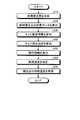
- FIG. 25 is a flowchart illustrating an example of a method for controlling the excavator according to the present embodiment.
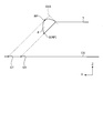
- FIG. 26 is a schematic diagram illustrating an example of a tilt operation plane according to the present embodiment.
- the global coordinate system is a coordinate system indicating an absolute position defined by a global navigation satellite system (GNSS) such as a global positioning system (GPS).
- GNSS global navigation satellite system
- GPS global positioning system
- the local coordinate system is a coordinate system that indicates a relative position with respect to a reference position of the construction machine.
- FIG. 1 is a perspective view showing an example of a construction machine 100 according to the present embodiment.
- the construction machine 100 is a hydraulic excavator will be described.
- the construction machine 100 is appropriately referred to as a hydraulic excavator 100.
- a hydraulic excavator 100 includes a working machine 1 that is operated by hydraulic pressure, an upper swing body 2 that is a vehicle body that supports the work machine 1, and a lower traveling body that is a traveling device that supports the upper swing body 2. 3, an operating device 30 for operating the work machine 1, and a control device 50 for controlling the work machine 1.
- the upper swing body 2 can swing around the swing axis RX while being supported by the lower traveling body 3.
- the upper swing body 2 has a cab 4 in which an operator is boarded, and a machine room 5 in which an engine and a hydraulic pump are accommodated.
- the cab 4 has a driver's seat 4S on which an operator is seated.
- the machine room 5 is disposed behind the cab 4.
- the lower traveling body 3 has a pair of crawler belts 3C.
- the excavator 100 travels by the rotation of the crawler belt 3C.
- the lower traveling body 3 may have a tire.
- the work machine 1 is supported by the upper swing body 2.
- the work machine 1 includes a boom 6 connected to the upper swing body 2 via a boom pin, an arm 7 connected to the boom 6 via an arm pin, and a bucket 8 connected to the arm 7 via a bucket pin and a tilt pin. And have.
- the bucket 8 has a cutting edge 9.
- the blade edge 9 of the bucket 8 is the tip of a straight blade provided on the bucket 8.
- the blade edge 9 of the bucket 8 may be a tip of a convex blade provided on the bucket 8.
- the boom 6 can be rotated with respect to the upper swing body 2 around a boom axis AX1 which is a rotation axis.
- the arm 7 is rotatable with respect to the boom 6 around an arm axis AX2 that is a rotation axis.
- the bucket 8 is rotatable with respect to the arm 7 around a bucket axis AX3 that is a rotation axis and a tilt axis AX4 that is a rotation axis orthogonal to the bucket axis AX3.
- the rotation axis AX1, the rotation axis AX2, and the rotation axis AX3 are parallel to each other.
- the rotation axes AX1, AX2, AX3 and the axis parallel to the turning axis RX are orthogonal to each other.
- the rotation axes AX1, AX2, and AX3 are parallel to the Y axis of the local coordinate system.
- the pivot axis RX is parallel to the Z axis of the local coordinate system.
- the direction parallel to the rotation axes AX1, AX2, AX3 indicates the vehicle width direction of the upper swing body 2.
- the direction parallel to the turning axis RX indicates the vertical direction of the upper turning body 2.
- the direction orthogonal to both the rotation axes AX1, AX2, AX3 and the turning axis RX indicates the front-rear direction of the upper turning body 2.
- the direction in which the work implement 1 is present is based on the operator seated on the driver's seat 4S.
- the work machine 1 is operated by the power generated by the hydraulic cylinder 10.
- the hydraulic cylinder 10 includes a boom cylinder 11 that operates the boom 6, an arm cylinder 12 that operates the arm 7, and a bucket cylinder 13 and a tilt cylinder 14 that operate the bucket 8.
- the work machine 1 includes a boom stroke sensor 16 that detects a boom stroke that indicates the drive amount of the boom cylinder 11, an arm stroke sensor 17 that detects an arm stroke that indicates the drive amount of the arm cylinder 12, and the drive of the bucket cylinder 13.
- a bucket stroke sensor 18 that detects a bucket stroke indicating the amount and a tilt stroke sensor 19 that detects a tilt stroke indicating the drive amount of the tilt cylinder 14 are provided.
- the boom stroke sensor 16 is disposed in the boom cylinder 11.
- the arm stroke sensor 17 is disposed in the arm cylinder 12.
- the bucket stroke sensor 18 is disposed in the bucket cylinder 13.
- the tilt stroke sensor 19 is disposed on the tilt cylinder 14.
- the operating device 30 is arranged in the cab 4.
- the operation device 30 includes an operation member that is operated by an operator of the excavator 100.
- the operator operates the operating device 30 to activate the work machine 1.
- the operation device 30 includes a right work machine operation lever 30R, a left work machine operation lever 30L, a tilt operation lever 30T, and an operation pedal 30F.
- the relationship between the operation direction of the right work machine operation lever 30R and the left work machine operation lever 30L, the operation direction of the work machine 1, and the turning direction of the upper swing body 2 may not be the above-described relation.
- the control device 50 includes a computer system.
- the control device 50 includes a processor such as a CPU (Central Processing Unit), a non-volatile memory such as a ROM (Read Only Memory) and a volatile memory such as a RAM (Random Access Memory), and an input / output And an interface device.
- a processor such as a CPU (Central Processing Unit)
- a non-volatile memory such as a ROM (Read Only Memory)
- a volatile memory such as a RAM (Random Access Memory)
- FIG. 2 is a side sectional view showing an example of the bucket 8 according to the present embodiment.
- FIG. 3 is a front view showing an example of the bucket 8 according to the present embodiment.
- the bucket 8 is a tilt type bucket.
- the work machine 1 has a bucket 8 that can rotate with respect to the arm 7 around a bucket axis AX3 and a tilt axis AX4 orthogonal to the bucket axis AX3.
- Bucket 8 is rotatably connected to arm 7 via bucket pin 8B.
- the bucket 8 is rotatably supported by the arm 7 via a tilt pin 8T.
- the bucket 8 is connected to the tip of the arm 7 via the connection member 90.
- the bucket pin 8 ⁇ / b> B connects the arm 7 and the connection member 90.
- the tilt pin 8T connects the connecting member 90 and the bucket 8 together.
- the bucket 8 is rotatably connected to the arm 7 via a connection member 90.
- the bucket 8 includes a bottom plate 81, a back plate 82, an upper plate 83, a side plate 84, and a side plate 85.
- the bucket 8 has a bracket 87 provided on the upper portion of the upper plate 83.
- the bracket 87 is installed at the front and rear positions of the upper plate 83.
- the bracket 87 is coupled to the connection member 90 and the tilt pin 8T.
- the connecting member 90 includes a plate member 91, a bracket 92 provided on the upper surface of the plate member 91, and a bracket 93 provided on the lower surface of the plate member 91.
- the bracket 92 is connected to the arm 7 and the second link pin 95P.
- the bracket 93 is installed on the upper portion of the bracket 87 and connected to the tilt pin 8T and the bracket 87.
- the bucket pin 8B connects the bracket 92 of the connection member 90 and the tip of the arm 7 together.
- the tilt pin 8T connects the bracket 93 of the connection member 90 and the bracket 87 of the bucket 8 together.
- the connecting member 90 and the bucket 8 are rotatable about the bucket axis AX3 with respect to the arm 7.
- the bucket 8 is rotatable about the tilt axis AX4 with respect to the connection member 90.
- the work machine 1 includes a first link member 94 that is rotatably connected to the arm 7 via the first link pin 94P, and a second link member that is rotatably connected to the bracket 92 via the second link pin 95P. 95.
- the base end portion of the first link member 94 is connected to the arm 7 via the first link pin 94P.
- the base end portion of the second link member 95 is connected to the bracket 92 via the second link pin 95P.
- the distal end portion of the first link member 94 and the distal end portion of the second link member 95 are connected via a bucket cylinder top pin 96.
- the tip of the bucket cylinder 13 is rotatably connected to the tip of the first link member 94 and the tip of the second link member 95 via the bucket cylinder top pin 96.
- the connecting member 90 rotates about the bucket axis AX3 together with the bucket 8.
- the tilt cylinder 14 is connected to each of a bracket 97 provided on the connection member 90 and a bracket 88 provided on the bucket 8.
- the rod of the tilt cylinder 14 is connected to the bracket 97 via a pin.
- the main body of the tilt cylinder 14 is connected to the bracket 88 via a pin.
- the bucket 8 rotates around the bucket axis AX3 by the operation of the bucket cylinder 13.
- the bucket 8 rotates around the tilt axis AX4 by the operation of the tilt cylinder 14.
- the tilt pin 8T rotates together with the bucket 8.
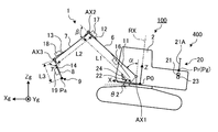
- FIG. 4 is a side view schematically showing the excavator 100 according to the present embodiment.
- FIG. 5 is a rear view schematically showing the excavator 100 according to the present embodiment.
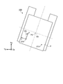
- FIG. 6 is a plan view schematically showing the excavator 100 according to the present embodiment.
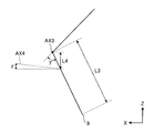
- FIG. 7 is a side view schematically showing the bucket 8 according to the present embodiment.
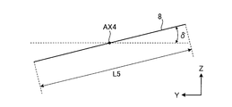
- FIG. 8 is a front view schematically showing the bucket 8 according to the present embodiment.
- the detection system 400 includes a position calculation device 20 that calculates the position of the upper swing body 2, and a work machine angle calculation device 24 that calculates the angle of the work machine 1. Have.
- the position calculator 20 includes a vehicle body position calculator 21 that detects the position of the upper swing body 2, an attitude calculator 22 that detects the attitude of the upper swing body 2, and an orientation calculator 23 that detects the orientation of the upper swing body 2. Including.
- the vehicle body position calculator 21 includes a GPS receiver.
- the vehicle body position calculator 21 is provided on the upper swing body 2.
- the vehicle body position calculator 21 detects the absolute position Pg of the upper swing body 2 defined by the global coordinate system.
- the absolute position Pg of the upper swing body 2 includes coordinate data in the Xg axis direction, coordinate data in the Yg axis direction, and coordinate data in the Zg axis direction.
- a plurality of GPS antennas 21 ⁇ / b> A are provided on the upper swing body 2.
- the GPS antenna 21 ⁇ / b> A receives a radio wave from a GPS satellite and outputs a signal generated based on the received radio wave to the vehicle body position calculator 21.
- the vehicle body position calculator 21 detects the position Pr where the GPS antenna 21A defined by the global coordinate system is installed based on the signal supplied from the GPS antenna 21A.
- the vehicle body position calculator 21 detects the absolute position Pg of the upper swing body 2 based on the position Pr where the GPS antenna 21A is installed.
- the vehicle body position calculator 21 detects a position Pra where one GPS antenna 21A is installed and a position Prb where the other GPS antenna 21A is installed.
- the vehicle body position calculator 21A performs an arithmetic process based on at least one of the position Pra and the position Prb, and calculates the absolute position Pg of the upper swing body 2.
- the absolute position Pg of the upper swing body 2 is the position Pra.
- the absolute position Pg of the upper swing body 2 may be the position Prb or a position between the position Pra and the position Prb.
- the attitude calculator 22 includes an inertial measurement unit (Inertial Measurement Unit: IMU).
- IMU Inertial Measurement Unit
- the posture calculator 22 is provided in the upper swing body 2.
- the posture calculator 22 calculates an inclination angle of the upper swing body 2 with respect to a horizontal plane (XgYg plane) defined by the global coordinate system.
- the tilt angle of the upper swing body 2 with respect to the horizontal plane includes a roll angle ⁇ 1 that indicates the tilt angle of the upper swing body 2 in the vehicle width direction and a pitch angle ⁇ 2 that indicates the tilt angle of the upper swing body 2 in the front-rear direction.
- the azimuth calculator 23 is based on the position Pra where one GPS antenna 21A is installed and the position Prb where the other GPS antenna 21A is installed. Is calculated.
- the reference orientation is, for example, north.
- the azimuth calculator 23 performs a calculation process based on the position Pra and the position Prb, and calculates the azimuth of the upper swing body 2 with respect to the reference azimuth.
- the azimuth calculator 23 calculates a straight line connecting the position Pra and the position Prb, and calculates the azimuth of the upper swing body 2 with respect to the reference azimuth based on the angle formed by the calculated straight line and the reference azimuth.
- the azimuth of the upper swing body 2 with respect to the reference azimuth includes a yaw angle ⁇ 3 indicating an angle formed by the reference azimuth and the azimuth of the upper swing body 2.
- the work machine angle calculation device 24 indicates the tilt angle of the boom 6 with respect to the Z axis of the local coordinate system based on the boom stroke detected by the boom stroke sensor 16.
- the boom angle ⁇ is calculated.
- the work machine angle calculation device 24 calculates an arm angle ⁇ indicating an inclination angle of the arm 7 with respect to the boom 6.
- the work machine angle calculation device 24 calculates a bucket angle ⁇ indicating the inclination angle of the blade edge 9 of the bucket 8 with respect to the arm 7 based on the bucket stroke detected by the bucket stroke sensor 18.
- the work machine angle calculation device 24 calculates a tilt angle ⁇ indicating the tilt angle of the bucket 8 with respect to the XY plane.
- the work machine angle calculation device 24 is configured to tilt the axis relative to the XY plane based on the boom stroke detected by the boom stroke sensor 16, the arm stroke detected by the arm stroke sensor 17, and the tilt stroke detected by the bucket stroke sensor 18.
- a tilt axis angle ⁇ indicating the tilt angle of AX4 is calculated.
- the boom angle ⁇ , the arm angle ⁇ , the bucket angle ⁇ , the tilt angle ⁇ , and the tilt axis angle ⁇ may be detected by, for example, an angle sensor provided in the work implement 10 without using the stroke sensor. Further, the angle of the work machine 10 is optically detected by a stereo camera or a laser scanner, and the boom angle ⁇ , arm angle ⁇ , bucket angle ⁇ , tilt angle ⁇ , and tilt axis angle ⁇ are calculated using the detection results. May be.
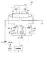
- FIGS. 9 and 10 are schematic diagrams illustrating an example of a hydraulic system 300 according to the present embodiment.
- the hydraulic cylinder 10 including the boom cylinder 11, the arm cylinder 12, the bucket cylinder 13, and the tilt cylinder 14 is driven by a hydraulic system 300.
- the hydraulic system 300 supplies hydraulic oil to the hydraulic cylinder 10 to drive the hydraulic cylinder 10.
- the hydraulic system 300 has a flow control valve 25.
- the flow control valve 25 controls the amount of hydraulic oil supplied to the hydraulic cylinder 10 and the direction in which the hydraulic oil flows.
- the hydraulic cylinder 10 has a cap side oil chamber 10A and a rod side oil chamber 10B.
- the cap side oil chamber 10A is a space between the cylinder head cover and the piston.
- the rod side oil chamber 10B is a space in which the piston rod is disposed.
- FIG. 9 is a schematic diagram showing an example of a hydraulic system 300 that operates the arm cylinder 12.
- the hydraulic system 300 is disposed in a variable displacement main hydraulic pump 31 that supplies hydraulic oil, a pilot pressure pump 32 that supplies pilot oil, oil passages 33A and 33B through which pilot oil flows, and oil passages 33A and 33B.
- right work machine operation lever 30R and left work machine operation lever 30L for adjusting the pilot pressure for the flow rate control valve 25.
- Including an operating device 30 and a control device 50 The right working machine operating lever 30R and the left working machine operating lever 30L of the operating device 30 are pilot hydraulic operating devices.
- the hydraulic oil supplied from the main hydraulic pump 31 is supplied to the arm cylinder 12 via the direction control valve 25.
- the flow rate control valve 25 is a slide spool type flow rate control valve that switches a direction in which hydraulic oil flows by moving a rod-shaped spool in the axial direction. As the spool moves in the axial direction, the supply of hydraulic oil to the cap-side oil chamber 10A of the arm cylinder 12 and the supply of hydraulic oil to the rod-side oil chamber 10B are switched. Further, the amount of hydraulic oil supplied per unit time to the arm cylinder 12 is adjusted by moving the spool in the axial direction. The cylinder speed is adjusted by adjusting the amount of hydraulic oil supplied to the arm cylinder 12.
- the flow control valve 25 is operated by the operating device 30. Pilot oil sent from the pilot pressure pump 32 is supplied to the operating device 30. Pilot oil sent from the main hydraulic pump 31 and decompressed by the pressure reducing valve may be supplied to the operating device 30.
- the operating device 30 includes a pilot pressure adjustment valve. Based on the operation amount of the operating device 30, the control valves 37A and 37B are operated, and the pilot pressure acting on the spool of the flow control valve 25 is adjusted. The flow control valve 25 is driven by the pilot pressure. By adjusting the pilot pressure by the operating device 30, the moving amount, moving speed, and moving direction of the spool in the axial direction are adjusted.
- the flow control valve 25 has a first pressure receiving chamber and a second pressure receiving chamber.
- the left work implement operation lever 30L When the left work implement operation lever 30L is operated to tilt to one side from the neutral position and the spool moves due to the pilot pressure in the oil passage 33A, the hydraulic oil from the main hydraulic pump 31 is supplied to the first pressure receiving chamber, The hydraulic oil is supplied to the cap side oil chamber 10A through the path 35A.
- the left work implement operating lever 30L is operated so as to tilt from the neutral position to the other side and the spool is moved by the pilot pressure in the oil passage 33B, the hydraulic oil from the main hydraulic pump 31 is supplied to the second pressure receiving chamber, The hydraulic oil is supplied to the rod side oil chamber 10B through the path 35B.
- the pressure sensor 34A detects the pilot pressure in the oil passage 33A.
- the pressure sensor 34B detects the pilot pressure in the oil passage 33B. Detection signals from the pressure sensors 33A and 33B are output to the control device 50. When performing work implement control, the control device 50 outputs a control signal to the control valves 37A and 37B to adjust the pilot pressure.
- the hydraulic system 300 that operates the boom cylinder 11 and the bucket cylinder 13 has the same configuration as the hydraulic system 300 that operates the arm cylinder 12. A detailed description of the hydraulic system 300 that operates the boom cylinder 11 and the bucket cylinder 13 is omitted.
- an intervention control valve that intervenes in the raising operation of the boom 6 may be connected to the oil passage 33 ⁇ / b> A connected to the boom cylinder 11.
- the right work machine operation lever 30R and the left work machine operation lever 30L of the operation device 30 may not be of a pilot hydraulic system.
- the right work machine operation lever 30R and the left work machine operation lever 30L output an electrical signal to the control device 50 based on the operation amount (tilt angle) of the right work machine operation lever 30R and the left work machine operation lever 30L, and control them.
- An electronic lever system that directly controls the flow control valve 25 based on a control signal of the device 50 may be used.
- FIG. 10 is a diagram schematically illustrating an example of a hydraulic system 300 that operates the tilt cylinder 14.
- the hydraulic system 300 includes a flow control valve 25 that adjusts the amount of hydraulic oil supplied to the tilt cylinder 14, control valves 37A and 37B that adjust pilot pressure acting on the flow control valve 25, a pilot pressure pump 32, and an operation pedal 30F.
- the operation pedal 30F of the operation device 30 is a pilot hydraulic operation device.
- the tilt operation lever 30T of the operation device 30 is an electronic lever type operation device.
- the tilt operation lever 30T includes operation buttons provided on the right work machine operation lever 30R and the left work machine operation lever 30L.
- the operating pedal 30F of the operating device 30 is connected to the pilot pressure pump 32.
- the operation pedal 30F is connected to an oil passage 38A through which pilot oil sent from the control valve 37A flows through a shuttle valve 36A.
- the operation pedal 30F is connected to an oil passage 38B through which pilot oil sent from the control valve 37B flows through a shuttle valve 36B.
- an operation signal generated by the operation of the tilt operation lever 30T is output to the control device 50.
- the control device 50 generates a control signal based on the operation signal output from the tilt operation lever 30T, and controls the control valves 37A and 37B.
- the control valves 37A and 37B are electromagnetic proportional control valves.
- the control valve 37A opens and closes the oil passage 38A based on the control signal.
- the control valve 37B opens and closes the oil passage 38B based on the control signal.
- the pilot pressure is adjusted based on the operation amount of the operation device 30.
- the control device 50 outputs a control signal to the control valves 37A and 37B to adjust the pilot pressure.
- FIG. 11 is a functional block diagram illustrating an example of the control system 200 according to the present embodiment.
- the control system 200 includes a control device 50 that controls the work implement 1, a position calculation device 20, a work implement angle calculation device 24, a control valve 37 (37A, 37B), and target construction data. And a generation device 70.
- the position calculation device 20 includes a vehicle body position calculator 21, an attitude calculator 22, and an azimuth calculator 23.
- the position calculation device 20 detects the absolute position Pg of the upper swing body 2, the posture of the upper swing body 2 including the roll angle ⁇ 1 and the pitch angle ⁇ 2, and the orientation of the upper swing body 2 including the yaw angle ⁇ 3.
- the work machine angle calculation device 24 detects angles of the work machine 1 including the boom angle ⁇ , the arm angle ⁇ , the bucket angle ⁇ , the tilt angle ⁇ , and the tilt axis angle ⁇ .
- the control valve 37 (37A, 37B) adjusts the amount of hydraulic oil supplied to the tilt cylinder 14.
- the control valve 37 operates based on a control signal from the control device 50.
- the target construction data generation device 70 includes a computer system.
- the target construction data generation device 70 generates target construction data indicating the target topography that is the target shape of the construction area.
- the target construction data indicates a three-dimensional target shape obtained after construction by the work machine 1.
- the target construction data generation device 70 is provided at a remote location of the excavator 100.
- the target construction data generation device 70 is installed in equipment of a construction management company, for example.
- the target construction data generation device 70 and the control device 50 can communicate wirelessly.
- the target construction data generated by the target construction data generation device 70 is transmitted to the control device 50 wirelessly.
- the target construction data generation device 70 and the control device 50 may be connected by wire, and the target construction data may be transmitted from the target construction data generation device 70 to the control device 50.
- the target construction data generation device 70 may include a recording medium that stores the target construction data
- the control device 50 may include a device that can read the target construction data from the recording medium.
- the target construction data generation device 70 may be provided in the excavator 100.
- the target construction data may be supplied to the target construction data generation device 70 of the excavator 100 by wire or wireless from an external management device that manages the construction, and the target construction data supplied by the target construction data generation device 70 may be stored. .
- the control device 50 includes a vehicle body position data acquisition unit 51, a work implement angle data acquisition unit 52, a specified point position data calculation unit 53A, a candidate specified point data calculation unit 53B, a target construction landform generation unit 54, and tilt data.
- a calculation unit 55, a tilt target landform calculation unit 56, a work implement control unit 57, a speed limit determination unit 58, a storage unit 59, and an input / output unit 60 are included.
- the functions of the work machine control unit 57 and the speed limit determination unit 58 are exhibited by the processor of the control device 50.
- the function of the storage unit 59 is performed by the storage device of the control device 50.
- the function of the input / output unit 60 is performed by the input / output interface device of the control device 50.
- the input / output unit 63 is connected to the position calculation device 20, the work machine angle calculation device 24, the control valve 37, and the target construction data generation device 70, and includes a vehicle body position data acquisition unit 51, a work machine angle data acquisition unit 52, a specified point.
- Position data calculation unit 53A, candidate specified point data calculation unit 53B, target construction landform generation unit 54, tilt data calculation unit 55, tilt target landform calculation unit 56, work implement control unit 57, speed limit determination unit 58, and storage unit 59 Data communication with
- the storage unit 59 stores specification data of the excavator 100 including work implement data.
- the vehicle body position data acquisition unit 51 acquires vehicle body position data from the position calculation device 20 via the input / output unit 60.
- the vehicle body position data includes the absolute position Pg of the upper swing body 2 defined by the global coordinate system, the attitude of the upper swing body 2 including the roll angle ⁇ 1 and the pitch angle ⁇ 2, and the orientation of the upper swing body 2 including the yaw angle ⁇ 3. Including.
- the work machine angle data acquisition unit 52 acquires the work machine angle data from the work machine angle calculation device 24 via the input / output unit 60.
- the work machine angle data detects angles of the work machine 1 including a boom angle ⁇ , an arm angle ⁇ , a bucket angle ⁇ , a tilt angle ⁇ , and a tilt axis angle ⁇ .
- the specified point position data calculation unit 53A calculates the position data of the specified point RP set in the bucket 8 based on the target construction landform, the width data of the bucket 8, and the outer surface data of the bucket 8.
- the specified point position data calculation unit 53 includes vehicle body position data acquired by the vehicle body position data acquisition unit 51, work machine angle data acquired by the work machine angle data acquisition unit 52, and work stored in the storage unit 59. Based on the machine data, the position data of the specified point RP set in the bucket 8 is calculated.
- the work implement data includes a boom length L1, an arm length L2, a bucket length L3, a tilt length L4, and a bucket width L5.
- the boom length L1 is a distance between the boom axis AX1 and the arm axis AX2.
- the arm length L2 is a distance between the arm axis AX2 and the bucket axis AX3.
- Bucket length L3 is the distance between bucket axis AX3 and blade edge 9 of bucket 8.
- the tilt length L4 is a distance between the bucket axis AX3 and the tilt axis AX4.
- the bucket width L5 is a distance between the side plate 84 and the side plate 85.
- FIG. 12 is a diagram schematically illustrating an example of the specified point RP set in the bucket 8 according to the present embodiment.
- a plurality of candidate specified points RPc that are candidates for the specified points RP used for tilt bucket control are set in the bucket 8.
- the candidate specified point RPc is set on the blade edge 9 of the bucket 8 and the outer surface of the bucket 8.
- a plurality of candidate specified points RPc are set in the bucket width direction at the blade edge 9.
- a plurality of candidate specified points RPc are set on the outer surface of the bucket 8.
- the work machine data includes bucket outer shape data indicating the shape and dimensions of the bucket 8.
- the bucket outer shape data includes the width data of the bucket 8 indicating the bucket width L5. Further, the bucket outer shape data includes outer surface data of the bucket 8 including contour data of the outer surface of the bucket 8. Further, the bucket outer shape data includes coordinate data of a plurality of candidate specified points RPc of the bucket 8 with the cutting edge 9 of the bucket 8 as a reference.
- the candidate specified point data calculation unit 53B calculates position data of a plurality of candidate specified points RPc that are candidates for the specified point RP.
- the candidate specified point data calculation unit 53B calculates the relative position of each of the plurality of candidate specified points RPc with respect to the reference position P0 of the upper swing body 2. Further, the specified point position data calculation unit 53 calculates the absolute position of each of the plurality of candidate specified points RPc.
- Candidate specified point data calculation unit 53B includes work implement data including boom length L1, arm length L2, bucket length L3, tilt length L4, and bucket outer shape data, boom angle ⁇ , arm angle ⁇ , bucket angle. Based on the work machine angle data including ⁇ , tilt angle ⁇ , and tilt axis angle ⁇ , the relative position of each of the plurality of candidate specified points RPc of the bucket 8 with respect to the reference position P0 of the upper swing body 2 can be calculated. As shown in FIG. 4, the reference position P ⁇ b> 0 of the upper swing body 2 is set to the swing axis RX of the upper swing body 2. The reference position P0 of the upper swing body 2 may be set to the boom axis AX1.
- the candidate specified point data calculation unit 53 ⁇ / b> B is based on the absolute position Pg of the upper swing body 2 detected by the position calculation device 20 and the relative position between the reference position P ⁇ b> 0 of the upper swing body 2 and the bucket 8.
- the absolute position Pa of 8 can be calculated.
- the relative position between the absolute position Pg and the reference position P0 is known data derived from the specification data of the excavator 100.
- the candidate specified point data calculation unit 53B includes vehicle body position data including the absolute position Pg of the upper swing body 2, the relative position between the reference position P0 of the upper swing body 2 and the bucket 8, work implement data, and work implement angle data. Based on the above, the absolute position of each of the plurality of candidate specified points RPc of the bucket 8 can be calculated.
- the candidate specified point RPc is not limited to a point as long as the width data of the bucket 8 and the outer surface data of the bucket 8 are included.
- the target construction landform generation unit 54 generates the target construction landform CS indicating the target shape of the excavation target based on the target construction data supplied from the target construction data generation device 70 and stored in the storage unit 62.
- the target construction data generation device 70 may supply the target construction topography generation unit 54 with the three-dimensional target topography data as the target construction data, or a plurality of line data or a plurality of point data indicating a part of the target shape. You may supply to the target construction topography production
- the target construction data generation device 70 supplies line data indicating a part of the target shape to the target construction topography generation unit 54 as the target construction data.
- FIG. 13 is a schematic diagram showing an example of the target construction data CD according to the present embodiment.
- the target construction data CD indicates the target topography of the construction area.
- the target landform includes a plurality of target construction landforms CS each represented by a triangular polygon.
- Each of the plurality of target construction terrain CS indicates a target shape to be excavated by the work machine 1.
- a point AP that is closest to the bucket 8 in the target construction topography CS is defined.
- a work machine operation plane WP that passes through the point AP and the bucket 8 and is orthogonal to the bucket axis AX3 is defined.
- the work machine operation plane WP is an operation plane in which the blade edge 9 of the bucket 8 is moved by at least one operation of the boom cylinder 11, the arm cylinder 12, and the bucket cylinder 13, and is parallel to the XZ plane.
- the specified point position data calculation unit 53A calculates the position data of the specified point RP whose vertical distance is specified closest to the point AP of the target construction landform CS based on the target construction landform CS and the outer shape data of the bucket 8. To do.
- the specified point RP at least data related to the width of the bucket 8 may be used. Further, the specified point RP may be designated by the operator.
- the target construction landform generation unit 54 acquires a line LX that is an intersection line between the work machine operation plane WP and the target construction landform CS. In addition, the target construction landform generation unit 54 acquires a line LY that passes through the point AP and is orthogonal to the line LX in the target construction landform CS. A line LY indicates an intersection line between the lateral motion plane VP and the target construction landform CS.
- FIG. 14 is a schematic diagram showing an example of the target construction landform CS according to the present embodiment.
- the target construction landform generation unit 54 acquires the line LX and the line LY, and generates the target construction landform CS indicating the target shape of the excavation target based on the line LX and the line LY.
- the control device 50 moves the bucket 8 along a line LX that is an intersection line between the work machine operation plane WP passing through the bucket 8 and the target construction landform CS.
- the tilt data calculation unit 55 calculates a tilt operation plane TP that passes through the specified point RP of the bucket 8 and is orthogonal to the tilt axis AX4 as tilt data.
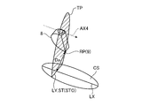
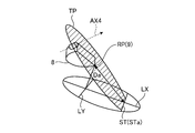
- FIG. 15 and 16 are schematic views showing an example of the tilt operation plane TP according to the present embodiment.
- FIG. 15 shows a tilt operation plane TP when the tilt axis AX4 is parallel to the target construction landform CS.
- FIG. 16 shows a tilt operation plane TP when the tilt axis AX4 is not parallel to the target construction landform CS.
- the tilt operation plane TP refers to an operation plane that passes through a specified point RP selected from a plurality of candidate specified points RPc specified in the bucket 8 and is orthogonal to the tilt axis AX4.
- the specified point RP is the specified point RP that has been determined to be most advantageous in tilt bucket control among the plurality of candidate specified points RPc.
- the specified point RP that is most advantageous in tilt bucket control is the specified point RP that is closest to the target construction landform CS.
- the specified point RP that is most advantageous in tilt bucket control may be the specified point RP at which the cylinder speed of the hydraulic cylinder 10 becomes the highest when tilt bucket control is performed based on the specified point RP.
- the tilt operation plane TP is an operation plane in which the specified point RP (blade edge 9) of the bucket 8 is moved by the operation of the tilt cylinder 14.
- the tilt of the tilt operation plane TP also changes.
- the work machine angle calculation device 24 can calculate the tilt axis angle ⁇ indicating the tilt angle of the tilt axis AX4 with respect to the XY plane.
- the tilt axis angle ⁇ is acquired by the work machine angle data acquisition unit 52.
- the position data of the specified point RP is calculated by the specified point position data calculating unit 53A.
- the tilt data calculation unit 55 performs tilting based on the tilt axis angle ⁇ of the tilt axis AX4 acquired by the work implement angle data acquisition unit 52 and the position of the specified point RP calculated by the specified point position data calculation unit 53A.
- An operation plane TP can be calculated.
- the tilt target landform calculation unit 56 extends in the lateral direction of the bucket 8 in the target construction landform CS based on the position data of the specified point RP selected from the plurality of candidate specified points RPc, the target construction landform CS, and the tilt data.
- the existing tilt target landform ST is calculated.
- the tilt target landform calculator 56 calculates the tilt target landform ST defined by the intersection of the target construction landform CS and the tilt operation plane TP. As shown in FIGS. 15 and 16, the tilt target landform ST is represented by an intersection line between the target construction landform CS and the tilt operation plane TP.
- the work machine control unit 57 outputs a control signal for controlling the hydraulic cylinder 10.
- the work implement control unit 57 tilts the bucket 8 about the tilt axis AX4 based on the operation distance Da indicating the distance between the specified point RP of the bucket 8 and the tilt target landform ST.
- Tilt stop control is performed to stop. That is, in the present embodiment, tilt stop control is performed based on the tilt target landform ST.
- the work implement control unit 57 stops the bucket 8 at the tilt target landform ST so that the bucket 8 that rotates by tilt does not exceed the tilt target landform ST.
- the tilt bucket control (tilt stop control) based on the tilt target landform ST and the tilt bucket control (tilt stop control) based on the line LY are substantially the same.
- the work implement control unit 57 performs tilt stop control based on the specified point RP having the shortest operating distance Da among the plurality of candidate specified points RPc set in the bucket 8. In other words, the work implement control unit 57 sets the closest target point RP to the tilt target landform ST so that the specified point RP closest to the tilt target landform ST among the plurality of candidate specified points RPc set in the bucket 8 does not exceed the tilt target landform ST. Tilt stop control is performed based on the operating distance Da between the nearest specified point RP and the tilt target landform ST.
- the speed limit determining unit 58 determines a speed limit U for the tilt rotation speed of the bucket 8 based on the operating distance Da.
- the speed limit determining unit 58 limits the tilt rotation speed when the operating distance Da is equal to or smaller than the threshold line distance H.
- FIG. 17 is a schematic diagram for explaining tilt stop control according to the present embodiment.
- a target construction landform CS is defined, and a speed limit intervention line IL is defined.
- the speed limit line IL is parallel to the tilt axis AX4 and is defined at a position separated from the tilt target landform ST by the line distance H.
- the line distance H is desirably set so as not to impair the operator's operational feeling.
- the work machine control unit 57 limits the tilt rotation speed of the bucket 8 when at least a part of the bucket 8 that rotates by tilt exceeds the speed limit intervention line IL and the operating distance Da becomes equal to or less than the line distance H.
- the speed limit determining unit 58 determines a speed limit U for the tilt rotation speed of the bucket 8 that exceeds the speed limit intervention line IL. In the example shown in FIG. 17, since a part of the bucket 8 exceeds the speed limit intervention line IL and the operating distance Da is smaller than the line distance H, the tilt rotation speed is limited.
- the speed limit determining unit 58 acquires the operating distance Da between the specified point RP and the tilt target landform ST in a direction parallel to the tilt operation plane TP. In addition, the speed limit determining unit 58 acquires a speed limit U corresponding to the operating distance Da. When it is determined that the operation distance Da is equal to or less than the line distance H, the work machine control unit 57 limits the tilt rotation speed.
- FIG. 18 is a diagram illustrating an example of the relationship between the operating distance Da and the speed limit U according to the present embodiment.
- FIG. 18 shows an example of the relationship between the operating distance Da and the speed limit U for stopping the tilt rotation of the bucket 8 based on the operating distance Da.
- the speed limit U is a speed that is uniformly determined according to the operating distance Da.
- the speed limit U is not set when the operating distance Da is greater than the line distance H, and is set when the operating distance Da is equal to or less than the line distance H.
- the speed limit U becomes smaller, and when the operating distance Da becomes zero, the speed limit U also becomes zero.
- the direction approaching the target construction landform CS is represented as a negative direction.
- the speed limit determining unit 58 calculates the moving speed Vr when the specified point RP moves toward the target construction landform CS (tilt target landform ST) based on the operation amount of the tilt operation lever 30T of the operation device 30.
- the moving speed Vr is a moving speed of the specified point RP in a plane parallel to the tilt operation plane TP.
- the moving speed Vr is calculated for each of the plurality of specified points RP.
- the moving speed Vr is calculated based on the current value output from the tilt operation lever 30T.
- a current corresponding to the operation amount of the tilt operation lever 30T is output from the tilt operation lever 30T.
- the storage unit 59 can store the cylinder speed of the tilt cylinder 14 corresponding to the operation amount of the tilt operation lever 30T.
- the cylinder speed may be obtained from detection by a cylinder stroke sensor.
- the speed limit determining unit 58 converts the cylinder speed of the tilt cylinder 14 into the moving speeds Vr of the plurality of specified points RP of the bucket 8 using the Jacobian determinant.
- the work machine control unit 58 When it is determined that the operating distance Da is equal to or less than the line distance H, the work machine control unit 58 performs speed limitation to limit the moving speed Vr of the specified point RP with respect to the target construction landform CS to the speed limit U.
- the work implement control unit 58 outputs a control signal to the control valve 37 in order to suppress the moving speed Vr of the specified point RP of the bucket 8.
- the work machine control unit 58 outputs a control signal to the control valve 37 so that the moving speed Vr of the specified point RP of the bucket 8 becomes the speed limit U according to the operating distance Da.
- the moving speed RP of the specified point RP of the bucket 8 that rotates by tilting becomes slower as the specified point RP approaches the target construction landform CS (tilt target landform ST), and the specified point RP (blade edge 9) becomes the target construction landform CD. When it reaches, it becomes zero.
- FIG. 19 is a schematic diagram for explaining the operation of the bucket 8 according to the present embodiment.
- the bucket 8 tilts and rotates in a state where the tilt axis AX4 is inclined with respect to the target construction landform CS.
- the operating distance Da between the bucket 8 that rotates by tilt and the target construction landform CS is sufficient, and the possibility that the bucket 8 that rotates by tilting about the tilt axis AX4 exceeds the target construction landform CS is low.
- FIG. 19 the state shown in FIG.
- tilt stop control is performed based on the vertical distance Db between the blade edge 9 and the target construction landform CS in the normal direction of the target construction landform CS, that is, a line extending in the Y-axis direction.
- the operating distance Da between the bucket 8 that rotates and the target construction landform CS is sufficient, and the bucket 8 that rotates and tilts around the tilt axis AX4 sets the target construction landform CS.
- tilt stop control is performed based on the vertical distance Db that is shorter than the operating distance Da.
- the lateral motion plane VP is a plane that is orthogonal to the work implement motion plane WP and passes through the point AP (see FIG. 13).
- the tilt rotation of the bucket 8 may be stopped unnecessarily.
- the working efficiency of the excavator 100 is lowered. Further, when the tilt rotation of the bucket 8 stops unnecessarily, the operator feels stress.
- a tilt operation plane TP is defined, and a tilt target landform ST that is an intersection line between the tilt operation plane TP and the target construction landform CS is derived.
- the work implement control unit 57 determines that the specified point RP exceeds the target construction landform CS based on the operating distance Da between the specified point RP closest to the tilt target landform ST and the target construction landform CS among the plurality of candidate specified points RPc.
- Tilt stop control is implemented so that there is no such thing. Since the tilt stop control is performed based on the operating distance Da longer than the vertical distance Db, the tilt rotation of the bucket 8 is unnecessarily stopped as compared with the case where the tilt stop control is performed based on the vertical distance Db. Is suppressed.
- FIG. 20 and 21 are schematic views showing an example of the tilt target landform ST according to the present embodiment.
- FIG. 20 is a diagram illustrating the tilt target landform ST when the target construction landform CS is parallel to the XY plane that is the reference plane of the upper swing body 2.
- FIG. 21 is a diagram illustrating the tilt target landform ST when the target construction landform CS is inclined with respect to the XY plane. From the state in which the tilt axis AX4 and the target construction landform CS are parallel, at least one of the boom cylinder 11, the arm cylinder 12, and the bucket cylinder 13 is operated, and the tilt axis AX4 is inclined with respect to the target construction landform CS.
- the tilt target landform ST moves from the tilt target landform ST0 to the tilt target landform STa.
- the target construction landform CS is parallel to the XY plane, and the tilt target landform ST is translated from the tilt target landform ST0 to the tilt target landform STa.
- the tilt target landform ST (ST0, STa) extends in the vehicle width direction parallel to the bucket axis AX3.
- the tilt stop control sequence based on the line LY (tilt target landform ST0) and the tilt target landform ST translated from the line LY and the reference tilt stop control sequence are substantially the same.
- the specified point RP is set to the target point RP by the tilt rotation of the bucket 8 both when the tilt axis AX4 is parallel to the target construction landform CS and when the tilt axis AX4 is not parallel to the target construction landform CS.
- the tilt stop control for stopping the tilt rotation of the bucket 8 has the same effect.
- FIG. 21 shows, as an example, a state where the bucket 8 tilts and rotates in a state where the target construction landform CS is inclined in the + Z direction toward the + X direction.
- the line LY extends in the vehicle width direction of the upper swing body 2.
- the tilt target landform ST does not move in parallel.
- the tilt target landform ST extends in the lateral direction of the bucket 8, but is not parallel to the bucket axis AX3.
- the tilt stop control is not performed based on the distance between the specified point RP of the bucket 8 and the tilt target landform ST, but the tilt stop is performed based on the distance between the specified point RP of the bucket 8 and the line LY.
- the control it is difficult to appropriately perform the tilt stop control. That is, when the tilt stop control is performed based on the line LY, the distance between the specified point RP and the line LY is a close distance that is limited (limits the tilt rotation). The rotation may be stopped unnecessarily.
- tilt stop control is performed based on the distance between the specified point RP of the bucket 8 and the tilt target landform ST. Even in the state where the target construction landform CS is inclined, when the tilt stop control is performed based on the operation distance Da between the specified point RP of the bucket 8 and the tilt target landform ST, the operation distance Da is not sufficiently limited. By having a sufficient distance, the tilt rotation of the bucket 8 is prevented from being stopped unnecessarily, and the tilt stop control is appropriately performed.
- FIG. 22, FIG. 23, and FIG. 24 a comparison of tilt stop control using the tilt target landform ST and the line LY is shown in FIG. 22, FIG. 23, and FIG. 24 in a state where the upper swing body 2 is inclined with respect to the target construction landform CS.
- FIG. 22 With the tilt rotation of the bucket 8, the bucket 8 (blade edge 9) portion where the vertical distance Db from the target construction landform CS has the shortest distance changes.
- the portion 9A that is the bucket left end of the blade edge 9 of the bucket 8 is closest to the target construction landform CS.
- the portion 9B that is the bucket right end of the blade edge 9 of the bucket 8 is closest to the target construction landform CS.
- the normal line of the target construction landform CS As shown in FIG. 22, when the bucket 8 is tilted and the part of the bucket 8 having the shortest vertical distance Db from the target construction landform CS in the normal direction of the target construction landform CS changes, the normal line of the target construction landform CS The position of the line LY where the distance from the part of the bucket 8 is the shortest in the direction changes from the part 9A to the part 9B in the target construction landform CS. That is, depending on the relationship between the target construction landform and the inclination of the vehicle body, the position of the line LY in the target construction landform CS where the distance to the part 9A is the shortest in the normal direction of the target construction landform CS and the distance from the part 9B are the largest. There is a case where the position is different from the position of the line LY in the target construction landform CS to be shortened. In other words, each time the bucket 8 rotates by tilt, the position of the line LY that defines the vertical distance Db changes.
- FIGS. FIG. 23 and FIG. 24 are diagrams showing how the line LY that defines the vertical distance Db changes each time the bucket 8 tilts.
- 23 and 24 show how the line LY changes when the upper swing body 2 is inclined in the lateral direction (+ Y direction or -Y direction) and the forward direction (+ X direction).
- the vertical distance Db suddenly changes when the position of the line LY changes from the line LYa in FIG. 23 to the line LYb in FIG. 24 due to the tilt rotation of the bucket 8.
- a phenomenon occurs in which the tilt rotation of the bucket 8 suddenly stops, where the speed limit U has changed. This behavior may give the operator a sense of incongruity or give an impact to the operator.
- the position of the tilt target landform ST does not change only by the bucket 8 being rotated. Therefore, a sudden stop of the tilting operation in which the operator feels uncomfortable does not occur, and the operator can perform a smooth excavation operation including tilt rotation without feeling uncomfortable.
- the normal line of the target construction landform CS As shown in FIG. 22, when the bucket 8 is tilted and the part of the bucket 8 having the shortest vertical distance Db from the target construction landform CS in the normal direction of the target construction landform CS changes, the normal line of the target construction landform CS The position of the line LY where the distance from the bucket 8 in the direction is the shortest changes in the target construction landform CS. That is, as shown in FIG. 22, the target construction landform where the distance between the position LY in the target construction landform CS where the distance to the part 9A is the shortest in the normal direction of the target construction landform CS and the part 9B is the shortest. It is different from the position of the line LY in CS. In other words, each time the bucket 8 rotates by tilt, the position of the line LY that defines the vertical distance Db changes.
- the position of the tilt target landform ST does not change only by the bucket 8 being tilted and rotated. Therefore, the excavation work using the bucket 8 capable of tilt rotation is smoothly performed.
- FIG. 25 is a flowchart illustrating an example of a method for controlling the excavator 100 according to the present embodiment.
- the target construction landform generation unit 54 generates the target construction landform CS based on the line LX and the line LY that are the target construction data supplied from the target construction data generation device 70 (step S10).
- Candidate specified point data calculation unit 53B has a plurality of work machine angle data acquired by work machine angle data acquisition unit 52 and a plurality of work machine data stored in storage unit 59. The position data of each candidate specified point RPc is calculated (step S20).
- the tilt data calculation unit 55 selects a preferential point RP that is most advantageous in tilt bucket control from a plurality of candidate prescription points RPc, and calculates a tilt operation plane TP that passes through the selected prescription point RP and is orthogonal to the tilt axis AX4 (step). S30).
- the tilt target landform calculation unit 56 calculates the tilt target landform ST where the target construction landform CS and the tilt operation plane TP intersect (step S40).
- the speed limit determining unit 58 calculates the operating distance Da between the specified point RP and the tilt target landform ST (step S50).
- the speed limit is determined based on the operating distance Da.
- the speed limit determining unit 58 determines a speed limit U corresponding to the operating distance Da (step S60).
- the work implement control unit 57 controls the control valve 37 based on the moving speed Vr of the specified point RP of the bucket 8 calculated from the operation amount of the tilt operation lever 30T and the speed limit U determined by the speed limit determining section 58. A control signal for is calculated.
- the work machine control unit 57 calculates a control signal for setting the moving speed Vr to the limit speed U and outputs the control signal to the control valve 37.
- the control valve 37 controls the pilot pressure based on the control signal output from the work implement control unit 57. As a result, the moving speed Vr of the specified point RP of the bucket 8 is limited (step S70).
- the tilt operation plane TP and the target construction landform CS that intersects the tilt axis AX4 and passes through the specified point RP of the bucket 8 intersect the tilt operation plane TP. Since the tilt target landform ST is set and the tilt stop control is performed based on the operating distance Da between the specified point RP and the tilt target landform ST, the tilt rotation of the bucket 8 may be stopped unnecessarily. It is suppressed. Therefore, the operator's stress is alleviated and a decrease in work efficiency of the excavator 100 is suppressed.
- the tilt stop control according to the present embodiment is performed by tilting the bucket 8 while the tilt axis AX is inclined with respect to the target construction landform CS. This is effective in that it is possible to suppress a decrease in work efficiency of the excavator 100.
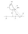
- the tilt stop control is performed based on the operating distance Da between the specified point RP set on the blade edge 9 of the bucket 8 and the target construction landform CS. As shown in FIG. 26, the tilt stop control may be performed based on the operating distance Da between the specified point RP set on the outer surface of the bucket 8 and the target construction landform CS.
- Tilt stop control may be performed so that the tilt rotation of the bucket 8 stops at a specified position different from the tilt target landform ST, which has a specified positional relationship with respect to the tilt target landform ST.
- tilt stop control is performed to stop the operation with respect to the tilt rotation
- intervention control in which the control device determines a control command in a direction opposite to the operation command may be performed for the operation.
- the construction machine 100 is a hydraulic excavator.
- the components described in the above-described embodiments can be applied to a construction machine having a work machine other than the hydraulic excavator.
- the work machine 1 in addition to the bucket shaft AX3 and the tilt shaft AX4, the work machine 1 may be provided with a rotation shaft that rotatably supports the bucket 8.
- the upper swing body 2 may be rotated by hydraulic pressure, or may be rotated by power generated by the electric actuator. Further, the work implement 1 may be operated not by the hydraulic cylinder 10 but by the power generated by the electric actuator.
Landscapes
- Engineering & Computer Science (AREA)
- Mining & Mineral Resources (AREA)
- Civil Engineering (AREA)
- General Engineering & Computer Science (AREA)
- Structural Engineering (AREA)
- Mechanical Engineering (AREA)
- Life Sciences & Earth Sciences (AREA)
- General Life Sciences & Earth Sciences (AREA)
- Paleontology (AREA)
- Operation Control Of Excavators (AREA)
Abstract
Description
図1は、本実施形態に係る建設機械100の一例を示す斜視図である。本実施形態においては、建設機械100が油圧ショベルである例について説明する。以下の説明においては、建設機械100を適宜、油圧ショベル100、と称する。
次に、本実施形態に係るバケット8について説明する。図2は、本実施形態に係るバケット8の一例を示す側断面図である。図3は、本実施形態に係るバケット8の一例を示す正面図である。本実施形態において、バケット8は、チルト式バケットである。
次に、本実施形態に係る油圧ショベル100の検出システム400について説明する。図4は、本実施形態に係る油圧ショベル100を模式的に示す側面図である。図5は、本実施形態に係る油圧ショベル100を模式的に示す背面図である。図6は、本実施形態に係る油圧ショベル100を模式的に示す平面図である。図7は、本実施形態に係るバケット8を模式的に示す側面図である。図8は、本実施形態に係るバケット8を模式的に示す正面図である。
次に、本実施形態に係る油圧ショベル100の油圧システム300の一例について説明する。図9及び図10は、本実施形態に係る油圧システム300の一例を示す模式図である。ブームシリンダ11、アームシリンダ12、バケットシリンダ13、及びチルトシリンダ14を含む油圧シリンダ10は、油圧システム300により駆動する。油圧システム300は、油圧シリンダ10に作動油を供給して、油圧シリンダ10を駆動する。油圧システム300は、流量制御弁25を有する。流量制御弁25は、油圧シリンダ10に対する作動油の供給量及び作動油が流れる方向を制御する。油圧シリンダ10は、キャップ側油室10A及びロッド側油室10Bを有する。キャップ側油室10Aは、シリンダヘッドカバーとピストンとの間の空間である。ロッド側油室10Bは、ピストンロッドが配置される空間である。油路35Aを介してキャップ側油室10Aに作動油が供給されることにより、油圧シリンダ10が伸びる。油路35Bを介してロッド側油室10Bに作動油が供給されることにより、油圧シリンダ10が縮む。
次に、本実施形態に係る油圧ショベル100の制御システム200について説明する。図11は、本実施形態に係る制御システム200の一例を示す機能ブロック図である。
次に、本実施形態に係る油圧ショベル100の制御方法の一例について説明する。図25は、本実施形態に係る油圧ショベル100の制御方法の一例を示すフローチャートである。
以上説明したように、本実施形態によれば、チルト式バケットにおいて、バケット8の規定点RPを通りチルト軸AX4と直交するチルト動作平面TP及び目標施工地形CSとチルト動作平面TPとが交差するチルト目標地形STを設定し、規定点RPとチルト目標地形STとの動作距離Daに基づいて、チルト停止制御を実施するようにしたので、バケット8のチルト回転が不必要に停止されることが抑制される。したがって、オペレータのストレスは緩和され、油圧ショベル100の作業効率の低下が抑制される。
2 上部旋回体
3 下部走行体
3C 履帯
4 運転室
5 機械室
6 ブーム
7 アーム
8 バケット
8B バケットピン
8T チルトピン
9 刃先
10 油圧シリンダ
10A キャップ側油室
10B ロッド側油室
11 ブームシリンダ
12 アームシリンダ
13 バケットシリンダ
14 チルトシリンダ
16 ブームストロークセンサ
17 アームストロークセンサ
18 バケットストロークセンサ
19 チルトストロークセンサ
20 位置演算装置
21 車体位置演算器
22 姿勢演算器
23 方位演算器
24 作業機角度演算装置
25 流量制御弁
30 操作装置
30F 操作ペダル
30L 作業機操作レバー
30T チルト操作レバー
31 メイン油圧ポンプ
32 パイロット圧ポンプ
33A,33B 油路
34A,34B 圧力センサ
35A,35B 油路
36A,36B シャトル弁
37A,37B 制御弁
38A,38B 油路
50 制御装置
51 車体位置データ取得部
52 作業機角度データ取得部
53A 規定点位置データ算出部
53B 候補規定点データ算出部
54 目標施工地形生成部
55 チルトデータ算出部
56 チルト目標地形算出部
57 作業機制御部
58 制限速度決定部
59 記憶部
60 入出力部
70 目標施工データ生成装置
81 底板
82 背板
83 上板
84 側板
85 側板
86 開口部
87 ブラケット
88 ブラケット
90 接続部材
91 プレート部材
92 ブラケット
93 ブラケット
94 第1リンク部材
94P 第1リンクピン
95 第2リンク部材
95P 第2リンクピン
96 バケットシリンダトップピン
97 ブラケット
100 油圧ショベル(建設機械)
200 制御システム
300 油圧システム
400 検出システム
AP 点
AX1 ブーム軸
AX2 アーム軸
AX3 バケット軸
AX4 チルト軸
CD 目標施工データ
CS 目標施工地形
Da 動作距離
Db 垂直距離
L1 ブーム長さ
L2 アーム長さ
L3 バケット長さ
L4 チルト長さ
L5 バケット幅
LX ライン
LY ライン
RP 規定点
RPc 候補規定点
RX 旋回軸
ST チルト目標地形
TP チルト動作平面
α ブーム角度
β アーム角度
γ バケット角度
δ チルト角度
ε チルト軸角度
θ1 ロール角度
θ2 ピッチ角度
θ3 ヨー角度
Claims (7)
- アームと、バケット軸及び前記バケット軸と直交するチルト軸のそれぞれを中心に前記アームに対して回転可能なバケットとを含む作業機を備える建設機械の制御システムであって、
掘削対象の目標形状を示す目標施工地形を生成する目標施工地形生成部と、
前記チルト軸を中心にチルト回転する前記バケットのチルトデータを算出するチルトデータ算出部と、
前記バケットの幅データを少なくとも含む前記バケットの外形データに基づいて、前記バケットに設定される規定点の位置データを算出する規定点位置データ算出部と、
前記規定点の位置データと前記目標施工地形と前記チルトデータとに基づいて、前記目標施工地形において前記バケットの側方方向に延在するチルト目標地形を算出するチルト目標地形算出部と、
前記規定点と前記チルト目標地形との距離に基づいて、前記バケットのチルト回転を制御する作業機制御部と、
を備える建設機械の制御システム。 - 前記チルトデータは、前記規定点を通り前記チルト軸と直交するチルト動作平面を含み、
前記チルト目標地形は、前記目標施工地形と前記チルト動作平面との交差部により規定され、
前記距離は、前記チルト目標地形と前記規定点とで規定される動作距離である、
請求項1に記載の建設機械の制御システム。 - 前記作業機制御部は、前記規定点と前記チルト目標地形との動作距離に基づいて、前記バケットのチルト回転を停止させるチルト停止制御を実施する、
請求項2に記載の建設機械の制御システム。 - 前記作業機制御部は、前記目標施工地形に対して前記チルト軸が傾斜した状態で前記バケットをチルト回転させ、前記チルト回転する前記バケットが前記目標施工地形を基準とする規定位置を超えないように、前記チルト停止制御を実施する、
請求項3に記載の建設機械の制御システム。 - 前記バケットの外形データから前記バケットに設定される複数の候補規定点の位置データを算出する候補規定点データ算出部を備え、
前記作業機制御部は、複数の前記候補規定点のうち前記動作距離が最も短い前記規定点に基づいて、前記チルト停止制御を実施する、
請求項3又は請求項4に記載の建設機械の制御システム。 - 上部旋回体と、
前記上部旋回体を支持する下部走行体と、
前記アームと前記バケットとを含み、前記上部旋回体に支持される作業機と、
請求項1から請求項5のいずれか一項に記載の建設機械の制御システムと、
を備える建設機械。 - アームと、バケット軸及び前記バケット軸と直交するチルト軸のそれぞれを中心に前記アームに対して回転可能なバケットとを含む作業機を備える建設機械の制御方法であって、
掘削対象の目標形状を示す目標施工地形を生成することと、
前記チルト軸を中心にチルト回転する前記バケットのチルトデータを算出することと、
前記バケットの幅に関するデータを少なくとも含む前記バケットの外形データに基づいて、前記バケットに設定される規定点の位置データを算出することと、
前記規定点の位置データと前記目標施工地形と前記チルトデータとに基づいて、前記目標施工地形において前記バケットの側方方向に延在するチルト目標地形を算出することと、
前記規定点と前記チルト目標地形との距離に基づいて、前記バケットのチルト回転を制御する制御信号を出力することと、
を含む建設機械の制御方法。
Priority Applications (6)
| Application Number | Priority Date | Filing Date | Title |
|---|---|---|---|
| DE112016000090.1T DE112016000090B4 (de) | 2016-05-31 | 2016-05-31 | Baumaschinensteuerungssystem, baumaschine und baumaschinensteuerungsverfahren |
| KR1020167036969A KR101838121B1 (ko) | 2016-05-31 | 2016-05-31 | 건설 기계의 제어 시스템, 건설 기계, 및 건설 기계의 제어 방법 |
| US15/322,813 US10196796B2 (en) | 2016-05-31 | 2016-05-31 | Construction machine control system, construction machine, and construction machine control method |
| JP2016545945A JP6046320B1 (ja) | 2016-05-31 | 2016-05-31 | 建設機械の制御システム、建設機械、及び建設機械の制御方法 |
| PCT/JP2016/066077 WO2016186218A1 (ja) | 2016-05-31 | 2016-05-31 | 建設機械の制御システム、建設機械、及び建設機械の制御方法 |
| CN201680000993.XA CN106460360B (zh) | 2016-05-31 | 2016-05-31 | 工程机械的控制系统、工程机械、以及工程机械的控制方法 |
Applications Claiming Priority (1)
| Application Number | Priority Date | Filing Date | Title |
|---|---|---|---|
| PCT/JP2016/066077 WO2016186218A1 (ja) | 2016-05-31 | 2016-05-31 | 建設機械の制御システム、建設機械、及び建設機械の制御方法 |
Publications (1)
| Publication Number | Publication Date |
|---|---|
| WO2016186218A1 true WO2016186218A1 (ja) | 2016-11-24 |
Family
ID=57320337
Family Applications (1)
| Application Number | Title | Priority Date | Filing Date |
|---|---|---|---|
| PCT/JP2016/066077 Ceased WO2016186218A1 (ja) | 2016-05-31 | 2016-05-31 | 建設機械の制御システム、建設機械、及び建設機械の制御方法 |
Country Status (6)
| Country | Link |
|---|---|
| US (1) | US10196796B2 (ja) |
| JP (1) | JP6046320B1 (ja) |
| KR (1) | KR101838121B1 (ja) |
| CN (1) | CN106460360B (ja) |
| DE (1) | DE112016000090B4 (ja) |
| WO (1) | WO2016186218A1 (ja) |
Cited By (4)
| Publication number | Priority date | Publication date | Assignee | Title |
|---|---|---|---|---|
| JP2020026819A (ja) * | 2018-08-09 | 2020-02-20 | 株式会社クボタ | 作業機の油圧システム及び作業機の油圧制御方法 |
| WO2021106938A1 (ja) * | 2019-11-27 | 2021-06-03 | 株式会社小松製作所 | 作業機械の制御システム、作業機械、作業機械の制御方法 |
| EP3854946A4 (en) * | 2018-09-20 | 2022-05-04 | Hitachi Construction Machinery Co., Ltd. | WORK MACHINE |
| WO2025206061A1 (ja) * | 2024-03-27 | 2025-10-02 | 日立建機株式会社 | 作業機械 |
Families Citing this family (15)
| Publication number | Priority date | Publication date | Assignee | Title |
|---|---|---|---|---|
| KR102547626B1 (ko) * | 2015-09-16 | 2023-06-23 | 스미도모쥬기가이고교 가부시키가이샤 | 쇼벨 |
| JP6633464B2 (ja) * | 2016-07-06 | 2020-01-22 | 日立建機株式会社 | 作業機械 |
| US11280063B2 (en) * | 2018-06-19 | 2022-03-22 | Komatsu Ltd. | Work vehicle control system and work vehicle control method |
| JP7275498B2 (ja) * | 2018-08-23 | 2023-05-18 | コベルコ建機株式会社 | 作業機械 |
| JP7315333B2 (ja) | 2019-01-31 | 2023-07-26 | 株式会社小松製作所 | 建設機械の制御システム、及び建設機械の制御方法 |
| JP7283910B2 (ja) * | 2019-02-01 | 2023-05-30 | 株式会社小松製作所 | 建設機械の制御システム、建設機械、及び建設機械の制御方法 |
| JP7197392B2 (ja) * | 2019-02-01 | 2022-12-27 | 株式会社小松製作所 | 建設機械の制御システム、建設機械、及び建設機械の制御方法 |
| JP2020133223A (ja) * | 2019-02-19 | 2020-08-31 | コベルコ建機株式会社 | 安全装置及び建設機械 |
| US20220178113A1 (en) * | 2019-04-05 | 2022-06-09 | Volvo Construction Equipment Ab | Construction equipment |
| DE102019207164A1 (de) * | 2019-05-16 | 2020-11-19 | Robert Bosch Gmbh | Verfahren zum Ablegen eines Werkzeugs einer Baumaschine |
| JP7396875B2 (ja) * | 2019-11-27 | 2023-12-12 | 株式会社小松製作所 | 作業機械の制御システム、作業機械、および作業機械の制御方法 |
| JP7572797B2 (ja) * | 2020-05-29 | 2024-10-24 | 株式会社小松製作所 | 作業システムおよび制御方法 |
| US11976444B2 (en) * | 2021-12-03 | 2024-05-07 | Deere & Company | Work machine with grade control using external field of view system and method |
| CN117248589B (zh) * | 2023-09-19 | 2026-04-03 | 徐州徐工挖掘机械有限公司 | 一种液压挖掘机重载挖掘防翘头的控制方法及系统 |
| LU505169B1 (de) * | 2023-09-26 | 2025-03-26 | Thomas Jansen | Baumaschine und Verfahren zur Herstellung eines Planums |
Citations (2)
| Publication number | Priority date | Publication date | Assignee | Title |
|---|---|---|---|---|
| JP2014074319A (ja) * | 2012-10-05 | 2014-04-24 | Komatsu Ltd | 掘削機械の表示システム、掘削機械及び掘削機械の表示用コンピュータプログラム |
| WO2015186180A1 (ja) * | 2014-06-02 | 2015-12-10 | 株式会社小松製作所 | 建設機械の制御システム、建設機械、及び建設機械の制御方法 |
Family Cites Families (7)
| Publication number | Priority date | Publication date | Assignee | Title |
|---|---|---|---|---|
| WO2014061790A1 (ja) | 2012-10-19 | 2014-04-24 | 株式会社小松製作所 | 油圧ショベルの掘削制御システム |
| DE112013000165B4 (de) | 2013-04-12 | 2019-02-07 | Komatsu Ltd. | Steuersystem für eine Baumaschine und Steuerverfahren |
| CN103852059B (zh) | 2014-03-25 | 2016-03-23 | 中国有色金属长沙勘察设计研究院有限公司 | 反铲挖掘机的铲斗定位装置及方法 |
| DE112014000080B4 (de) | 2014-05-30 | 2018-06-21 | Komatsu Ltd. | Arbeitsmaschinensteuersystem, Arbeitsmaschine,Baggersteuersystem und Arbeitsmaschinensteuerverfahren |
| WO2015186179A1 (ja) | 2014-06-02 | 2015-12-10 | 株式会社小松製作所 | 建設機械の制御システム、建設機械、及び建設機械の制御方法 |
| JP5921692B1 (ja) | 2014-06-03 | 2016-05-24 | 株式会社小松製作所 | 掘削機械の制御システム及び掘削機械 |
| US9663917B2 (en) | 2015-10-16 | 2017-05-30 | Komatsu Ltd. | Work vehicle, bucket device, and method for obtaining tilt angle |
-
2016
- 2016-05-31 US US15/322,813 patent/US10196796B2/en active Active
- 2016-05-31 WO PCT/JP2016/066077 patent/WO2016186218A1/ja not_active Ceased
- 2016-05-31 JP JP2016545945A patent/JP6046320B1/ja active Active
- 2016-05-31 KR KR1020167036969A patent/KR101838121B1/ko active Active
- 2016-05-31 CN CN201680000993.XA patent/CN106460360B/zh active Active
- 2016-05-31 DE DE112016000090.1T patent/DE112016000090B4/de active Active
Patent Citations (2)
| Publication number | Priority date | Publication date | Assignee | Title |
|---|---|---|---|---|
| JP2014074319A (ja) * | 2012-10-05 | 2014-04-24 | Komatsu Ltd | 掘削機械の表示システム、掘削機械及び掘削機械の表示用コンピュータプログラム |
| WO2015186180A1 (ja) * | 2014-06-02 | 2015-12-10 | 株式会社小松製作所 | 建設機械の制御システム、建設機械、及び建設機械の制御方法 |
Cited By (10)
| Publication number | Priority date | Publication date | Assignee | Title |
|---|---|---|---|---|
| JP2020026819A (ja) * | 2018-08-09 | 2020-02-20 | 株式会社クボタ | 作業機の油圧システム及び作業機の油圧制御方法 |
| JP7091185B2 (ja) | 2018-08-09 | 2022-06-27 | 株式会社クボタ | 作業機の油圧システム及び作業機の油圧制御方法 |
| EP3854946A4 (en) * | 2018-09-20 | 2022-05-04 | Hitachi Construction Machinery Co., Ltd. | WORK MACHINE |
| WO2021106938A1 (ja) * | 2019-11-27 | 2021-06-03 | 株式会社小松製作所 | 作業機械の制御システム、作業機械、作業機械の制御方法 |
| JP2021085216A (ja) * | 2019-11-27 | 2021-06-03 | 株式会社小松製作所 | 作業機械の制御システム、作業機械、作業機械の制御方法 |
| KR20220086671A (ko) * | 2019-11-27 | 2022-06-23 | 가부시키가이샤 고마쓰 세이사쿠쇼 | 작업 기계의 제어 시스템, 작업 기계, 작업 기계의 제어 방법 |
| JP7402026B2 (ja) | 2019-11-27 | 2023-12-20 | 株式会社小松製作所 | 作業機械の制御システム、作業機械、作業機械の制御方法 |
| KR102712415B1 (ko) | 2019-11-27 | 2024-09-30 | 가부시키가이샤 고마쓰 세이사쿠쇼 | 작업 기계의 제어 시스템, 작업 기계, 작업 기계의 제어 방법 |
| US12139881B2 (en) | 2019-11-27 | 2024-11-12 | Komatsu Ltd. | Work machine control system, work machine, and work machine control method |
| WO2025206061A1 (ja) * | 2024-03-27 | 2025-10-02 | 日立建機株式会社 | 作業機械 |
Also Published As
| Publication number | Publication date |
|---|---|
| US10196796B2 (en) | 2019-02-05 |
| DE112016000090B4 (de) | 2021-09-02 |
| JPWO2016186218A1 (ja) | 2017-06-01 |
| US20170342678A1 (en) | 2017-11-30 |
| DE112016000090T5 (de) | 2017-04-27 |
| KR101838121B1 (ko) | 2018-03-13 |
| KR20170136415A (ko) | 2017-12-11 |
| JP6046320B1 (ja) | 2016-12-14 |
| CN106460360A (zh) | 2017-02-22 |
| CN106460360B (zh) | 2018-06-12 |
Similar Documents
| Publication | Publication Date | Title |
|---|---|---|
| JP6046320B1 (ja) | 建設機械の制御システム、建設機械、及び建設機械の制御方法 | |
| JP6099834B1 (ja) | 建設機械の制御システム、建設機械、及び建設機械の制御方法 | |
| JP7129907B2 (ja) | 建設機械の制御システム、建設機械、及び建設機械の制御方法 | |
| JP6099835B1 (ja) | 作業機械の制御システム、作業機械及び作業機械の制御方法 | |
| KR101907938B1 (ko) | 건설 기계의 제어 장치 및 건설 기계의 제어 방법 | |
| JP6209276B2 (ja) | 作業機械の制御装置、作業機械及び作業機械の制御方法 | |
| CN106460361B (zh) | 作业机械的控制系统、作业机械以及作业机械的控制方法 | |
| CN105431596A (zh) | 建筑机械的控制系统、建筑机械及建筑机械的控制方法 | |
| JP6781068B2 (ja) | 作業機械の制御システム、作業機械及び作業機械の制御方法 | |
| JP6781067B2 (ja) | 建設機械の制御システム、建設機械、及び建設機械の制御方法 | |
| JP6680849B2 (ja) | 作業機械の制御システム、及び作業機械の制御方法 | |
| WO2018123470A1 (ja) | 建設機械の制御装置及び建設機械の制御方法 |
Legal Events
| Date | Code | Title | Description |
|---|---|---|---|
| ENP | Entry into the national phase |
Ref document number: 2016545945 Country of ref document: JP Kind code of ref document: A |
|
| ENP | Entry into the national phase |
Ref document number: 20167036969 Country of ref document: KR Kind code of ref document: A |
|
| WWE | Wipo information: entry into national phase |
Ref document number: 15322813 Country of ref document: US |
|
| 121 | Ep: the epo has been informed by wipo that ep was designated in this application |
Ref document number: 16796611 Country of ref document: EP Kind code of ref document: A1 |
|
| WWE | Wipo information: entry into national phase |
Ref document number: 112016000090 Country of ref document: DE |
|
| 122 | Ep: pct application non-entry in european phase |
Ref document number: 16796611 Country of ref document: EP Kind code of ref document: A1 |