WO2016186193A1 - 排ガス混合装置 - Google Patents
排ガス混合装置 Download PDFInfo
- Publication number
- WO2016186193A1 WO2016186193A1 PCT/JP2016/064985 JP2016064985W WO2016186193A1 WO 2016186193 A1 WO2016186193 A1 WO 2016186193A1 JP 2016064985 W JP2016064985 W JP 2016064985W WO 2016186193 A1 WO2016186193 A1 WO 2016186193A1
- Authority
- WO
- WIPO (PCT)
- Prior art keywords
- gas
- exhaust gas
- flow path
- partition plate
- gas flow
- Prior art date
- Legal status (The legal status is an assumption and is not a legal conclusion. Google has not performed a legal analysis and makes no representation as to the accuracy of the status listed.)
- Ceased
Links
Images


Classifications
-
- B—PERFORMING OPERATIONS; TRANSPORTING
- B01—PHYSICAL OR CHEMICAL PROCESSES OR APPARATUS IN GENERAL
- B01D—SEPARATION
- B01D53/00—Separation of gases or vapours; Recovering vapours of volatile solvents from gases; Chemical or biological purification of waste gases, e.g. engine exhaust gases, smoke, fumes, flue gases, aerosols
- B01D53/34—Chemical or biological purification of waste gases
- B01D53/92—Chemical or biological purification of waste gases of engine exhaust gases
- B01D53/94—Chemical or biological purification of waste gases of engine exhaust gases by catalytic processes
-
- B—PERFORMING OPERATIONS; TRANSPORTING
- B01—PHYSICAL OR CHEMICAL PROCESSES OR APPARATUS IN GENERAL
- B01D—SEPARATION
- B01D53/00—Separation of gases or vapours; Recovering vapours of volatile solvents from gases; Chemical or biological purification of waste gases, e.g. engine exhaust gases, smoke, fumes, flue gases, aerosols
- B01D53/34—Chemical or biological purification of waste gases
- B01D53/74—General processes for purification of waste gases; Apparatus or devices specially adapted therefor
- B01D53/86—Catalytic processes
- B01D53/90—Injecting reactants
-
- B—PERFORMING OPERATIONS; TRANSPORTING
- B01—PHYSICAL OR CHEMICAL PROCESSES OR APPARATUS IN GENERAL
- B01D—SEPARATION
- B01D53/00—Separation of gases or vapours; Recovering vapours of volatile solvents from gases; Chemical or biological purification of waste gases, e.g. engine exhaust gases, smoke, fumes, flue gases, aerosols
- B01D53/34—Chemical or biological purification of waste gases
- B01D53/74—General processes for purification of waste gases; Apparatus or devices specially adapted therefor
- B01D53/86—Catalytic processes
- B01D53/8621—Removing nitrogen compounds
- B01D53/8625—Nitrogen oxides
- B01D53/8631—Processes characterised by a specific device
-
- B—PERFORMING OPERATIONS; TRANSPORTING
- B01—PHYSICAL OR CHEMICAL PROCESSES OR APPARATUS IN GENERAL
- B01D—SEPARATION
- B01D53/00—Separation of gases or vapours; Recovering vapours of volatile solvents from gases; Chemical or biological purification of waste gases, e.g. engine exhaust gases, smoke, fumes, flue gases, aerosols
- B01D53/34—Chemical or biological purification of waste gases
- B01D53/74—General processes for purification of waste gases; Apparatus or devices specially adapted therefor
- B01D53/86—Catalytic processes
-
- B—PERFORMING OPERATIONS; TRANSPORTING
- B01—PHYSICAL OR CHEMICAL PROCESSES OR APPARATUS IN GENERAL
- B01D—SEPARATION
- B01D53/00—Separation of gases or vapours; Recovering vapours of volatile solvents from gases; Chemical or biological purification of waste gases, e.g. engine exhaust gases, smoke, fumes, flue gases, aerosols
- B01D53/34—Chemical or biological purification of waste gases
- B01D53/74—General processes for purification of waste gases; Apparatus or devices specially adapted therefor
- B01D53/86—Catalytic processes
- B01D53/8621—Removing nitrogen compounds
- B01D53/8625—Nitrogen oxides
-
- B—PERFORMING OPERATIONS; TRANSPORTING
- B01—PHYSICAL OR CHEMICAL PROCESSES OR APPARATUS IN GENERAL
- B01F—MIXING, e.g. DISSOLVING, EMULSIFYING OR DISPERSING
- B01F23/00—Mixing according to the phases to be mixed, e.g. dispersing or emulsifying
- B01F23/10—Mixing gases with gases
-
- B—PERFORMING OPERATIONS; TRANSPORTING
- B01—PHYSICAL OR CHEMICAL PROCESSES OR APPARATUS IN GENERAL
- B01F—MIXING, e.g. DISSOLVING, EMULSIFYING OR DISPERSING
- B01F23/00—Mixing according to the phases to be mixed, e.g. dispersing or emulsifying
- B01F23/20—Mixing gases with liquids
- B01F23/21—Mixing gases with liquids by introducing liquids into gaseous media
- B01F23/213—Mixing gases with liquids by introducing liquids into gaseous media by spraying or atomising of the liquids
-
- B—PERFORMING OPERATIONS; TRANSPORTING
- B01—PHYSICAL OR CHEMICAL PROCESSES OR APPARATUS IN GENERAL
- B01F—MIXING, e.g. DISSOLVING, EMULSIFYING OR DISPERSING
- B01F25/00—Flow mixers; Mixers for falling materials, e.g. solid particles
- B01F25/30—Injector mixers
- B01F25/31—Injector mixers in conduits or tubes through which the main component flows
-
- B—PERFORMING OPERATIONS; TRANSPORTING
- B01—PHYSICAL OR CHEMICAL PROCESSES OR APPARATUS IN GENERAL
- B01F—MIXING, e.g. DISSOLVING, EMULSIFYING OR DISPERSING
- B01F25/00—Flow mixers; Mixers for falling materials, e.g. solid particles
- B01F25/40—Static mixers
- B01F25/42—Static mixers in which the mixing is affected by moving the components jointly in changing directions, e.g. in tubes provided with baffles or obstructions
- B01F25/43—Mixing tubes, e.g. wherein the material is moved in a radial or partly reversed direction
- B01F25/432—Mixing tubes, e.g. wherein the material is moved in a radial or partly reversed direction with means for dividing the material flow into separate sub-flows and for repositioning and recombining these sub-flows; Cross-mixing, e.g. conducting the outer layer of the material nearer to the axis of the tube or vice-versa
- B01F25/4321—Mixing tubes, e.g. wherein the material is moved in a radial or partly reversed direction with means for dividing the material flow into separate sub-flows and for repositioning and recombining these sub-flows; Cross-mixing, e.g. conducting the outer layer of the material nearer to the axis of the tube or vice-versa the subflows consisting of at least two flat layers which are recombined, e.g. using means having restriction or expansion zones
-
- F—MECHANICAL ENGINEERING; LIGHTING; HEATING; WEAPONS; BLASTING
- F23—COMBUSTION APPARATUS; COMBUSTION PROCESSES
- F23J—REMOVAL OR TREATMENT OF COMBUSTION PRODUCTS OR COMBUSTION RESIDUES; FLUES
- F23J15/00—Arrangements of devices for treating smoke or fumes
-
- F—MECHANICAL ENGINEERING; LIGHTING; HEATING; WEAPONS; BLASTING
- F23—COMBUSTION APPARATUS; COMBUSTION PROCESSES
- F23J—REMOVAL OR TREATMENT OF COMBUSTION PRODUCTS OR COMBUSTION RESIDUES; FLUES
- F23J15/00—Arrangements of devices for treating smoke or fumes
- F23J15/006—Layout of treatment plant
-
- F—MECHANICAL ENGINEERING; LIGHTING; HEATING; WEAPONS; BLASTING
- F23—COMBUSTION APPARATUS; COMBUSTION PROCESSES
- F23J—REMOVAL OR TREATMENT OF COMBUSTION PRODUCTS OR COMBUSTION RESIDUES; FLUES
- F23J15/00—Arrangements of devices for treating smoke or fumes
- F23J15/02—Arrangements of devices for treating smoke or fumes of purifiers, e.g. for removing noxious material
-
- B—PERFORMING OPERATIONS; TRANSPORTING
- B01—PHYSICAL OR CHEMICAL PROCESSES OR APPARATUS IN GENERAL
- B01D—SEPARATION
- B01D2251/00—Reactants
- B01D2251/20—Reductants
- B01D2251/206—Ammonium compounds
- B01D2251/2062—Ammonia
-
- B—PERFORMING OPERATIONS; TRANSPORTING
- B01—PHYSICAL OR CHEMICAL PROCESSES OR APPARATUS IN GENERAL
- B01D—SEPARATION
- B01D2257/00—Components to be removed
- B01D2257/40—Nitrogen compounds
- B01D2257/404—Nitrogen oxides other than dinitrogen oxide
-
- B—PERFORMING OPERATIONS; TRANSPORTING
- B01—PHYSICAL OR CHEMICAL PROCESSES OR APPARATUS IN GENERAL
- B01D—SEPARATION
- B01D2258/00—Sources of waste gases
- B01D2258/02—Other waste gases
- B01D2258/0283—Flue gases
-
- F—MECHANICAL ENGINEERING; LIGHTING; HEATING; WEAPONS; BLASTING
- F23—COMBUSTION APPARATUS; COMBUSTION PROCESSES
- F23J—REMOVAL OR TREATMENT OF COMBUSTION PRODUCTS OR COMBUSTION RESIDUES; FLUES
- F23J2215/00—Preventing emissions
- F23J2215/10—Nitrogen; Compounds thereof
Definitions
- the present invention relates to an exhaust gas mixing device, and more particularly, a flow path of an exhaust gas duct on the upstream side of a denitration catalyst layer of a denitration device into which combustion exhaust gas to which a reducing agent for reducing nitrogen oxides in combustion exhaust gas is added is introduced.
- the present invention relates to an exhaust gas mixing apparatus including a plurality of gas mixers provided in a cross section.
- a denitration device is generally used to treat nitrogen oxides in combustion exhaust gas generated from combustion facilities.
- the combustion facility is a combustion facility such as a gas turbine in addition to boilers such as coal burning, gas burning, and oil burning.
- the denitration device adds a reducing agent such as ammonia and ammonia compounds to the exhaust gas upstream, and reacts the reducing agent with nitrogen oxides in the exhaust gas on the denitration catalyst provided in the denitration device to reduce it to nitrogen.
- the reducing agent is basically supplied as a gas, or the solution is sprayed directly into the exhaust gas. In the case of solution spraying, since it is heated and vaporized by high-temperature exhaust gas, it is eventually added in a gaseous state.
- the amount of exhaust gas to be denitrated reaches 3 million m 3 N / h in the case of a 1000 MW class power generation facility, for example.
- the reducing agent is 9000 m 3 N / h including the air for dilution. That is, since the amount of exhaust gas is about 300 times that of the reducing agent gas, it is necessary to uniformly disperse a very small amount of reducing agent gas in a large amount of exhaust gas in order to increase the denitration efficiency. In particular, restrictions on the emission of nitrogen oxides (NOx) to the outside tend to be strengthened, and for example, a denitration rate of 90% or more is required.
- NOx nitrogen oxides
- the slip ammonia concentration at which unreacted ammonia as a reducing agent flows out from the denitration apparatus is regulated to several ppm or less.
- the flow passage cross section of the exhaust gas duct is divided into a plurality of regions, a plurality of ammonia injection nozzles are arranged in each region, and the ammonia injection amount is controlled independently for each region. It has been proposed. According to this, it is possible to make a fine adjustment by actually measuring the NOx concentration or slip ammonia concentration in the flow passage cross section at the outlet of the desulfurization catalyst and feedback-controlling the ammonia injection amount for each region.
- Patent Document 2 it is generally performed to use a gas mixer as shown in Patent Document 2. This is installed in an exhaust gas duct between the ammonia injection nozzle and the denitration catalyst, and an effect of mixing exhaust gas and ammonia gas is expected.
- Patent No. 4069196 Japanese Patent No. 4539930 Japanese Utility Model Publication No. 6-31826
- the site where the increase / decrease in the ammonia injection amount varies depending on the laying shape such as the direction of the exhaust gas duct, the presence or absence of guide vanes, the exhaust gas duct size, etc. Adjustment is not easy.
- the exhaust gas flow velocity and the NOx concentration vary in each part of the cross section of the exhaust gas duct.
- the ammonia concentration in the portion on the extension does not necessarily increase or decrease.
- CV standard deviation / average value
- a mixer as shown in Patent Document 2 generally improves the rectification effect by increasing the pressure loss, and makes the NH 3 / NOx molar ratio uniform by the effect of equalizing the exhaust gas flow rate upstream of the ammonia nozzle. To make it easier.
- the effect of homogenizing by mixing the portions having different nitrogen oxide concentrations with each other occurs, and the molar ratio can be made uniform at a relatively short distance.
- the pressure loss is high and the fan power increases.
- the problem to be solved by the present invention is to provide a compact exhaust gas mixing device that can increase the pressure loss and accelerate the mixing of the exhaust gas.
- the present invention provides an exhaust gas duct on the upstream side of a denitration apparatus including a denitration catalyst into which the combustion exhaust gas to which a reducing agent for reducing nitrogen oxides in the combustion exhaust gas is added is introduced.
- the gas mixer is configured such that one of two parallel surfaces of the rectangular parallelepiped space serves as a gas inflow surface and the other serves as a gas outflow surface.
- Said of the surface And characterized in that it comprises a gas flow path partition plate for guiding the region.
- the combustion exhaust gas flowing into each region of the exhaust gas inflow surface is centered between the gas inflow surface and the gas outflow surface by the gas flow path partition plate.
- the gas flow direction is deviated by one region and flows out from the gas outflow surface.
- the combustion exhaust gas flowing through the gas mixer of the present invention receives a turning force with respect to the main flow and is discharged from the gas outflow surface.
- the exhaust gas mixing apparatus of the present invention can also be applied to a case where a plurality of denitration catalyst layers are provided in the flow direction of the exhaust gas, and a case where the exhaust gas mixing device is provided in the cross section of the flow path between the denitration catalyst layers.
- the gas flow path partition plate is formed of at least four partition plate elements having a common line connecting the center of the gas inflow surface and the gas outflow surface, and the partition plate element includes the gas What is formed by the bending board which interrupts
- the gas flow path preferably divides the gas inflow surface and the gas outflow surface into four regions by orthogonal straight lines parallel to the sides of the surfaces and passing through the centers of the surfaces. According to this, a swirl flow is effectively formed with respect to the main flow of the combustion exhaust gas flowing into the gas mixer of the present invention. Moreover, an increase in pressure loss can be suppressed.
- the gas flow path is divided into four rectangular regions by orthogonal straight lines in which the gas inflow surface and the gas outflow surface are parallel to the sides of the surfaces and pass through the centers of the surfaces.
- the gas flow path partition plate is arranged by rotating four partition plate elements having a common side line segment connecting the center of the gas inflow surface and the gas outflow surface at a 90 ° pitch around the common side.
- the partition plate element is preferably formed by a bent plate that blocks the gas flow between the rectangular regions at symmetrical positions of the gas inflow surface and the gas outflow surface.
- the partition plate element calculates the three-dimensional coordinates [xyz] of each vertex of the rectangular area of the gas inflow surface from the intersection of the orthogonal two straight lines. [000], [100], [110], [010] respectively in the clockwise direction, and the three-dimensional coordinates [xyz] of each vertex of the rectangular area of the gas outflow surface at the symmetrical position of these vertices are orthogonal to each other.
- [001], [101], [111], and [011] are respectively clockwise from the intersection of two straight lines, it is preferable to form four triangular plates A to D described below.
- the triangular plate A has a line segment L 1 connecting the vertex [100] and the vertex [011] as a base, and a point P 1 on the line segment L 2 connecting the vertex [110] and the vertex [111].
- Triangular plate B is a base of the common sides L 3, a flat plate of a triangle whose vertices point P 2 on the line L 1.
- Triangular plate C is the line segment L 4 of the apex [000] and connecting the vertices [100] and bottom, and flat triangles as vertices the points P 2.
- Triangular plate D is a line segment L 5 connecting the vertices [001] and the apex [011] and bottom, and flat triangles as vertices the points P 2.
- the present invention is not limited to the gas flow path partition plate that imparts a clockwise turning force, and may apply a counterclockwise turning force to the flow of inflowing combustion exhaust gas.
- the combustion exhaust gas flowing into the upper left region of the 1 ⁇ 4 region on the gas inflow surface side is converted into the lower left portion of the 1 ⁇ 4 region on the gas outflow surface side.
- the flue gas flowing out from the upper right region and flowing into the lower left region of the 1 ⁇ 4 region on the gas inflow surface side is made to flow out from the lower right upper left region of the 1 ⁇ 4 region on the gas outflow surface side
- the gas flow path partition plate is formed by partition plates composed of four triangular plates that are sequentially shifted.
- the present invention it is possible to provide an exhaust gas mixing device that can increase the pressure loss and accelerate the mixing of the exhaust gas. Moreover, since the exhaust gas mixing device of the present invention is compact without requiring a space in the traveling direction of the exhaust gas, it can be additionally installed in a narrow portion of the exhaust gas duct.
- Example 1 of the gas mixer of this invention It is a perspective view explaining the structure of Example 1 of the gas mixer of this invention. It is a figure which shows the structure of the exhaust gas mixing apparatus which has arrange
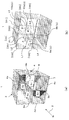
- FIG. 1A shows a perspective configuration diagram of a gas mixer 1 according to a first embodiment of the present invention.
- the gas mixer 1 according to the first embodiment includes a flow path of an exhaust gas duct on the upstream side of a denitration apparatus including a denitration catalyst into which a combustion exhaust gas to which a reducing agent that reduces nitrogen oxides in the combustion exhaust gas is added is introduced.
- a denitration apparatus including a denitration catalyst into which a combustion exhaust gas to which a reducing agent that reduces nitrogen oxides in the combustion exhaust gas is added is introduced.
- the flow passage section of a denitration apparatus equipped with a denitration catalyst used in a large power generation facility is rectangular, and the flow passage section of an exhaust gas duct for introducing exhaust gas into the denitration apparatus is often rectangular.
- the gas mixer 1 of the present embodiment is configured by dividing the cross-section of the exhaust gas duct into a plurality of rectangular regions, and stacking gas mixers of sizes corresponding to the rectangular regions in multiple stages and arranging a plurality of rows. It demonstrates as what is applied to an exhaust gas mixing apparatus.
- the gas mixer 1 of the first embodiment has a gas flow path in a rectangular parallelepiped space 3 through which the combustion exhaust gas G flowing in from the direction shown by the arrow 2 in the drawing is circulated.
- the gas flow path of the present embodiment is formed by a rectangular flow path wall 4 having a rectangular cross section in which flat plates 4 (a to d) are arranged on a plane parallel to the gas inflow direction 2 of the cuboid space 3.
- the opening surface on the near side of the rectangular flow path wall 4 having a rectangular cross section is a gas inflow surface
- the opening surface on the back side is a gas outflow surface.
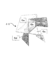
- a gas flow path partition plate 6 composed of four partition plate elements 6a to 6d formed in the same shape is disposed inside the rectangular flow path wall 4 having a rectangular cross section.
- the partition plate elements 6a to 6d are all formed in the same shape.
- the gas inflow surface and the gas outflow surface of the gas flow path of the first embodiment are parallel to the sides of the gas inflow surface and the gas outflow surface, respectively, and are orthogonal straight lines passing through the centers 7 and 8 of the gas inflow surface and the gas outflow surface ( 9a, 9b) and (10a, 10b) are divided into four rectangular regions each having the same symmetrical area.
- Gas flow path partition plate 6, the combustion exhaust gas G flowing into the respective regions of the gas inlet side, around the line L 3 connecting the centers 7,8 gas entry surface and gas exit surface, timepiece in this embodiment It is formed so as to lead to each region of the gas outflow surface at a position where the regions are shifted one by one around. That is, the partition plate elements 6a ⁇ 6d, the line segment L 3 as common sides, at 90 ° pitch around a common sides, in the present embodiment is installed by rotating clockwise.
- the partition plate elements 6a to 6d are formed of bent plates that block the gas flow between the rectangular regions at symmetrical positions of the gas inflow surface and the gas outflow surface.
- FIG.1 (b) the structure of the partition plate element 6a is demonstrated in detail.
- the partition plate element 6a is composed of four triangular plates A to D.
- the three-dimensional coordinates [xyz] of each vertex of the rectangular area of the gas inflow surface are set to [000], [100], [110], and [010], respectively, clockwise from the intersection 7 of the orthogonal straight lines 9a and 9b.
- the three-dimensional coordinates [xyz] of each vertex of the rectangular region of the gas outflow surface at the symmetrical position of these vertices are respectively [001], [101], [101], [101], [111] and [011].
- Triangular plate A is to the bottom of the line segment L 1 connecting the vertices [011] and apex [100], the apex [110] and apex [111] of the triangle whose vertices P 1 point on a line segment L 2 connecting the It is a flat plate.
- Triangular plate B is a base of the common sides L 3, is a flat plate of a triangle whose vertices point P 2 on the line segment L 1.
- Triangular plate C is the base of the line segment L 4 connecting the vertices [100] and apex [000], a flat triangle the point P 2 and the vertex.
- Triangular plate D has a bottom line segment L 5 connecting the vertices [001] and apex [011], a flat triangle the point P 2 and the vertex. Position on the line segment L 2 of the point P 1 of the triangle plate A may cause the back and forth within 1/3 of the line segment L 2 length from the center of the line segment L 2. The position of the triangular plates B ⁇ point P 2 of D also may be back and forth within 1/3 of the length of the line L 1 from the center of the line segment L 1.
- the partition plate device 6b ⁇ 6d like the partition plate element 6a, are formed from triangular plates A ⁇ D in the same shape, a line segment L 3 as a common side, the common sides In this embodiment, it is rotated clockwise at a pitch of 90 °.
- the edge portions of the partition plate elements 6a to 6d that are in contact with the flat plates 4 (a to d) are respectively fixed to the flat plates 4 (a to d) by welding or the like.
- the edges of the partition plate elements 6a to 6d that do not contact the flat plate 4 (ad) are orthogonal straight lines (9a, 9b), (10a, 10b) and a line segment L 3. Are fixed to a rod-like support member 11 such as a pipe installed by welding or the like.
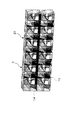
- FIG. 2 shows an example of an exhaust gas mixing apparatus in which the gas mixer 1 of the first embodiment is configured as a lattice element.
- the gas mixer 1 is arranged on the entire cross section in the exhaust gas duct 25 on the upstream side of the denitration apparatus so as to be adjacent to each other.
- the rectangular flow path wall 4 having a rectangular cross section in which the flat plates 4 (a to d) are arranged surrounds the structure of the gas flow path partition plates 6a to 6d. When not provided, it is as illustrated. Note that FIG.
- the exhaust gas mixing apparatus of the present invention includes a plurality of gas mixers 1 in a plurality of stages and a plurality of rows in at least part of the flow path cross section of the exhaust gas duct 25 on the upstream side of the denitration apparatus. , Arranged and configured. That is, when the gas mixers 1 are arranged in a plurality of stages in two stages, the horizontal partition plate 14 and the vertical partition plate 15 are provided, and the outer peripheral wall of the gas mixer 1 uses the outer peripheral wall of the exhaust gas duct 25. .
- a denitration apparatus equipped with a denitration catalyst used in a large power generation facility has a square cross section of the flow path, and a cross section of an exhaust gas duct upstream thereof is often rectangular. Therefore, it is desirable to determine the cross-sectional dimension of the gas flow path of the gas mixer 1 according to the shorter dimension of the cross-sectional dimension of the exhaust gas duct.
- the size of the exhaust gas duct was assumed to be 18.4 m ⁇ 4.6 m.
- the cross-sectional size of the gas mixer 1 was set to 2.3 m which is a half of the short dimension of 4.6 m in consideration of ease of manufacture and maintainability.
- the size of the gas mixer 1 is appropriately set according to the gas flow rate, the molar ratio distribution, and the size of the adjustment region of the reducing agent injection nozzle.
- the gas mixer 1 of the present invention is a type that causes a swirl flow, it is desirable that the gas mixer 1 has a square cross section when viewed from the gas flow direction.
- the aspect ratio may be slightly changed according to the size of the exhaust gas duct. In the first embodiment, a square of 2.3 ⁇ 2.3 m is used, so that the horizontal dimension of the exhaust gas duct can be sufficiently entered.
- the combustion exhaust gas G flowing into the four rectangular regions of the exhaust gas inflow surface is separated from the gas inflow surface and the gas by the gas flow path partition plates 6 (a to d). around the line segment L 3 connecting the centers of the outflow surface (e.g., clockwise) to one by one area gas flow direction is flowing out from the gas outlet surface is drift.
- the main flow of the combustion exhaust gas G flowing through the gas mixer 1 of the present embodiment receives a swirling force and is discharged from the gas outflow surface as a swirling flow.
- a reducing agent such as ammonia
- the variation rate CV (standard deviation / average value) of the molar ratio of NH 3 / NOx is 7% or less, and the variation rate of the gas flow rate.
- CV (standard deviation / average value) can be 15% or less.
- the increase in the pressure loss of the gas mixer 1 can be suppressed.
- FIG. 3 shows a perspective configuration diagram of the gas mixer 30 according to the second embodiment of the present invention.
- the difference between the second embodiment and the gas mixer 1 of the first embodiment is that the flat plates 4a and 4c are arranged only on two upper and lower surfaces parallel to the gas inflow direction 2 of the rectangular parallelepiped space 3, and the other 2 in the vertical direction.
- the difference is that the gas flow path is formed by omitting the surface partition plate.
- a pair of two opposing faces among the four faces parallel to the gas flow flowing into the rectangular parallelepiped space is formed by a flat plate, and the other pair of two faces are open. Since the other points are the same as those of the first embodiment, the same reference numerals are given and description thereof is omitted.
- FIG. 4 is a perspective configuration diagram of the gas mixer 40 according to the third embodiment of the present invention.
- the third embodiment is different from the gas mixer 1 of the first embodiment or the gas mixer 30 of the second embodiment in that all four flat plates 4a to 4d parallel to the gas inflow direction 2 of the rectangular parallelepiped space 3 are omitted. It is to have done. That is, four surfaces parallel to the gas flow flowing into the rectangular parallelepiped space 3 are opened.
- the partition plate elements 6a to 6d of the gas flow path partition plate 6 have their edges secured to a bar-like support member such as a pipe by welding or the like to ensure strength.
- Comparative Example 1 is an example of an exhaust gas duct in which the gas mixers of Examples 1 to 3 are not installed.
- Comparative Example 2 is an example in which an exhaust gas mixing apparatus is configured by installing the gas mixer of Patent Document 2.
- Comparative Example 3 is an example in which the exhaust gas mixing device is configured by installing the gas mixer of Patent Document 3 shown in FIG. 5A in the exhaust gas duct 25 as shown in FIG. 5B.
- the ammonia nozzle also used a structure that reproduced the actual machine size, and the ammonia injection amount was changed according to the inlet gas flow rate.
- each of Examples 1 to 3 has a pressure loss of about 40 Pa higher than that of Comparative Example 1 that does not include a gas mixer, but the NH 3 / NOx molar ratio CV is low. It can be seen that the properties are excellent. That is, in Comparative Example 1, since there is no gas mixer, there is no problem with the gas flow rate CV, but the NH 3 / NOx molar ratio CV is the highest at 9.2%, and the normally required 7% was not satisfied. .
- Examples 1 to 3 each have a low pressure loss and a low NH 3 / NOx molar ratio CV and a gas flow rate CV as compared with Comparative Example 2, so that both mixing and rectifying performance are excellent. That is, in Comparative Example 2, the NH 3 / NOx molar ratio CV hardly changes compared to Comparative Example 1, and it is considered that the effect is small as compared with Examples 1 to 3.
- the gas mixer of Comparative Example 3 has a structure in which a pair of two triangular plates 17 and 18 are opposed to each other at the apex portion, and the gas flow entering from the inlet is two upstream triangular plates. After 17 are once dispersed in two directions, the next two triangular plates 18 are in alternate positions so that they merge and exit from the exit surface. That is, the effect is mainly to restrict the gas flow, and it is not a structure that gives a large swirl flow to the gas flow. From these results, it was found that the gas mixers of Examples 1 to 3 of the present invention were highly effective for Comparative Examples 1 to 3.
- the present invention has been described based on the embodiments, but the present invention is not limited thereto, and can be implemented in a form that is modified or changed within the scope of the gist of the present invention. It will be apparent to those skilled in the art that such variations or modifications are naturally within the scope of the present invention.
- the partition plate elements 6a to 6d of the gas flow path partition plate 6 are formed by combining the triangular plates A to D, but the present invention is not limited to this.
- the combustion exhaust gas G flowing into the respective regions of the gas inlet surface, each of the gas exit surface of the position shifted one by one region around the line L 3 connecting the centers of the gas inlet side and the gas outlet surface You may form using the flat plate processed into the gentle curved surface so that it may guide
- the gas flow path partition plate 6 of the first to third embodiments allows the combustion exhaust gas G flowing into each region of the gas inflow surface to rotate clockwise in a line segment connecting the center of the gas inflow surface and the gas outflow surface.
- the region was formed so as to be led to each region of the gas outflow surface at a position shifted by one.
- the combustion exhaust gas G flowing into each region of the gas inflow surface is disposed at a position where the regions are shifted one by one in the counterclockwise direction of the line segment connecting the center of the gas inflow surface and the gas outflow surface. Even if it is formed so as to lead to each region of the outflow surface, the technical effect is the same.
- the gas flow path of the present invention is formed by joining the sides of a plurality of isosceles triangular plate materials, and the joint portions of the plate materials are adjacent to each other in a concave shape or a convex shape, or the concave portion and the convex portion are adjacent to each other. It may be formed so as to be alternately alternated with respect to the gas flow direction.
Landscapes
- Engineering & Computer Science (AREA)
- Chemical & Material Sciences (AREA)
- Environmental & Geological Engineering (AREA)
- Chemical Kinetics & Catalysis (AREA)
- Oil, Petroleum & Natural Gas (AREA)
- Biomedical Technology (AREA)
- Analytical Chemistry (AREA)
- General Chemical & Material Sciences (AREA)
- Health & Medical Sciences (AREA)
- Mechanical Engineering (AREA)
- General Engineering & Computer Science (AREA)
- Dispersion Chemistry (AREA)
- Combustion & Propulsion (AREA)
- Exhaust Gas Treatment By Means Of Catalyst (AREA)
- Exhaust Gas After Treatment (AREA)
- Chimneys And Flues (AREA)
- Treating Waste Gases (AREA)
Abstract
Description
三角形板Aは、前記頂点[100]と前記頂点[011]を結ぶ線分L1を底辺とし、前記頂点[110]と前記頂点[111]を結ぶ線分L2上の点P1を頂点とする三角形の平板とする。三角形板Bは、共通辺L3を底辺とし、前記線分L1上の点P2を頂点とする三角形の平板とする。三角形板Cは、前記頂点[000]と前記頂点[100]を結ぶ線分L4を底辺とし、前記点P2を頂点とする三角形の平板とする。三角形板Dは、前記頂点[011]と前記頂点[001]を結ぶ線分L5を底辺とし、前記点P2を頂点とする三角形の平板とする。

3 直方体空間
4 矩形流路壁
6 ガス流路仕切板
6a~6d 仕切板要素
7 ガス流入面の中心
8 ガス流出面の中心
9a、9b 直交二直線
10a、10b 直交二直線
A~D 三角形板
L1~L5 線分
P1、P2 点
Claims (10)
- 燃焼排ガス中の窒素酸化物を還元する還元剤が添加された前記燃焼排ガスが導入される脱硝装置の脱硝触媒層の前流側の排ガスダクトの流路断面に設けられる複数のガス混合器を備えた排ガス混合装置において、
前記ガス混合器は、直方体空間の平行な2つの面の一方をガス流入面とし、他方をガス流出面として前記燃焼排ガスが流通されるガス流路を有し、
前記ガス流路は、前記ガス流入面と前記ガス流出面が、それぞれ各面の中心を通る直線によって対称な同一面積の少なくとも四つの領域に区分され、前記ガス流入面の前記各領域に流入される前記燃焼排ガスを、前記ガス流入面と前記ガス流出面の前記中心を結ぶ線分の回りに前記領域を一つずつずらした位置の前記ガス流出面の前記各領域に導くガス流路仕切板を備えてなることを特徴とする排ガス混合装置。 - 前記ガス流路仕切板は、前記ガス流入面と前記ガス流出面の前記中心を結ぶ線分を共通辺とする少なくとも四つの仕切板要素から形成され、
前記仕切板要素は、前記ガス流入面と前記ガス流出面の対称位置の前記領域間のガス流れを遮る曲折板により形成されてなることを特徴とする請求項1に記載の排ガス混合装置。 - 前記ガス流路は、前記ガス流入面と前記ガス流出面が、当該各面の辺に平行でかつ当該各面の中心を通る直交二直線によりそれぞれ四つの矩形領域に区分され、
前記ガス流路仕切板は、前記ガス流入面と前記ガス流出面の前記中心を結ぶ線分を共通辺とする四つの仕切板要素を、前記共通辺の周りに90°ピッチで回転させて配置されてなり、
前記仕切板要素は、前記ガス流入面と前記ガス流出面の対称位置の前記矩形領域間のガス流れを遮る曲折板によりに形成されてなることを特徴とする請求項1に記載の排ガス混合装置。 - 前記仕切板要素は、前記ガス流入面の前記矩形領域の各頂点の三次元座標[xyz]を前記直交二直線の交点から時計回りにそれぞれ[000]、[100]、[110]、[010]とし、これらの頂点の対称位置の前記ガス流出面の前記矩形領域の各頂点の三次元座標[xyz]を、前記直交二直線の交点から時計回りにそれぞれ[001]、[101]、[111]、[011]としたとき、
前記頂点[100]と前記頂点[011]を結ぶ線分L1を底辺とし、前記頂点[110]と前記頂点[111]を結ぶ線分L2上の点P1を頂点とする三角形板Aと、
前記共通辺L3を底辺とし、前記線分L1上の点P2を頂点とする三角形板Bと、
前記頂点[000]と前記頂点[100]を結ぶ線分L4を底辺とし、前記点P2を頂点とする三角形板Cと、
前記頂点[011]と前記頂点[001]を結ぶ線分L5を底辺とし、前記点P2を頂点とする三角形板Dとから形成されてなることを特徴とする請求項3に記載の排ガス混合装置。 - 前記ガス混合器は、前記直方体空間に流入するガス流に平行な面が平板により筒状に形成されていることを特徴とする請求項1乃至4のいずれか1項に記載の排ガス混合装置。
- 前記ガス混合器は、前記直方体空間に流入するガス流に平行な4面のうち対向する一対の二つの面が平板により形成され、他の一対の二つの面が開放されていることを特徴とする請求項1乃至4のいずれか1項に記載の排ガス混合装置。
- 前記ガス混合器は、前記直方体空間に流入するガス流に平行な四つの面が開放されていることを特徴とする請求項1乃至4のいずれか1項に記載の排ガス混合装置。
- 前記仕切板要素は、前記直方体空間の外面の平板に接する縁部は当該平板に固定され、前記直方体空間の外面の平板に接しない縁部は棒状の支持部材に固定されていることを特徴とする請求項1に記載の排ガス混合装置。
- 前記ガス混合器を、前記脱硝装置の前流側の排ガスダクトの流路断面の少なくとも一部に、複数段、複数列、配置してなることを特徴とする請求項1に記載の排ガス混合装置。
- 燃焼排ガス中の窒素酸化物を還元する還元剤が添加された前記燃焼排ガスが導入される脱硝装置の脱硝触媒層の前流側の排ガスダクトの流路断面に設けられる複数のガス混合器を備えた排ガス混合装置において、
前記ガス混合器は、直方体空間の平行な2つの面の一方をガス流入面とし、他方をガス流出面として前記燃焼排ガスが流通されるガス流路を有し、
前記ガス流路は、複数の二等辺三角形の板材の辺同士を接合させて形成され、前記板材の接合部が凹状または凸状となる接合部を隣り合わせ、あるいは凹部と凸部がガス流れ方向に対して順次交互となるように形成されてなることを特徴とする排ガス混合装置。
Priority Applications (4)
| Application Number | Priority Date | Filing Date | Title |
|---|---|---|---|
| ES201790047A ES2653937B2 (es) | 2015-05-21 | 2016-04-07 | Aparato para mezclar gas de escape |
| CN201680029061.8A CN107614091B (zh) | 2015-05-21 | 2016-05-20 | 废气混合装置 |
| KR1020177033328A KR102017485B1 (ko) | 2015-05-21 | 2016-05-20 | 연도 가스 혼합 장치 |
| US15/574,084 US10343116B2 (en) | 2015-05-21 | 2016-05-20 | Flue gas mixing apparatus |
Applications Claiming Priority (2)
| Application Number | Priority Date | Filing Date | Title |
|---|---|---|---|
| JP2015103605A JP6591197B2 (ja) | 2015-05-21 | 2015-05-21 | 排ガス混合装置 |
| JP2015-103605 | 2015-05-21 |
Publications (1)
| Publication Number | Publication Date |
|---|---|
| WO2016186193A1 true WO2016186193A1 (ja) | 2016-11-24 |
Family
ID=57320499
Family Applications (1)
| Application Number | Title | Priority Date | Filing Date |
|---|---|---|---|
| PCT/JP2016/064985 Ceased WO2016186193A1 (ja) | 2015-05-21 | 2016-05-20 | 排ガス混合装置 |
Country Status (7)
| Country | Link |
|---|---|
| US (1) | US10343116B2 (ja) |
| JP (1) | JP6591197B2 (ja) |
| KR (1) | KR102017485B1 (ja) |
| CN (1) | CN107614091B (ja) |
| ES (1) | ES2653937B2 (ja) |
| TW (1) | TWI634940B (ja) |
| WO (1) | WO2016186193A1 (ja) |
Cited By (3)
| Publication number | Priority date | Publication date | Assignee | Title |
|---|---|---|---|---|
| CN111249904A (zh) * | 2020-03-19 | 2020-06-09 | 中国华电科工集团有限公司 | 一种双三角翼型静态混合器及混合气体的方法 |
| WO2021218076A1 (zh) * | 2020-04-29 | 2021-11-04 | 华能国际电力股份有限公司 | 一种适用于煤粉锅炉高温烟气sncr脱硝的新型混合器结构 |
| CN113975949A (zh) * | 2021-12-28 | 2022-01-28 | 山东东源新材料科技有限公司 | 一种石化行业烟气脱硝装置及其使用方法 |
Families Citing this family (9)
| Publication number | Priority date | Publication date | Assignee | Title |
|---|---|---|---|---|
| CN103877837B (zh) * | 2014-02-26 | 2016-01-27 | 中国科学院过程工程研究所 | 一种应用于低温氧化脱硝技术的烟道臭氧分布器及其布置方式 |
| GB2550130B (en) * | 2016-05-09 | 2021-01-27 | James Muggleton Kevin | System including passive blender for use with gas from an unconventional source |
| JP7182956B2 (ja) * | 2018-08-31 | 2022-12-05 | 三菱重工業株式会社 | 排ガス浄化装置 |
| JP2020044461A (ja) * | 2018-09-14 | 2020-03-26 | 三菱日立パワーシステムズ株式会社 | 脱硝装置 |
| CN109289514B (zh) * | 2018-11-28 | 2023-11-17 | 长沙凯天工研院环保服务有限公司 | 一种scr脱硝烟气混合器及其系统 |
| CN109499358B (zh) * | 2018-12-26 | 2024-12-03 | 福建龙净脱硫脱硝工程有限公司 | 烟气混合升温装置和中低温scr脱硝系统 |
| CN109966899B (zh) * | 2019-05-07 | 2024-01-26 | 华能国际电力股份有限公司 | 一种实现煤粉锅炉烟气高效sncr脱硝的槽式混合器装置 |
| CN113351009B (zh) * | 2020-03-06 | 2022-11-11 | 大唐环境产业集团股份有限公司 | 一种scr烟气混合装置和scr烟气脱硝系统 |
| JP7371142B2 (ja) * | 2022-01-14 | 2023-10-30 | 三菱重工業株式会社 | 脱硝装置及びボイラ並びに脱硝装置の設置方法 |
Citations (7)
| Publication number | Priority date | Publication date | Assignee | Title |
|---|---|---|---|---|
| US4830792A (en) * | 1985-04-27 | 1989-05-16 | Gerd Wilhelm | Vortex-inducing packing of pyramid-type elements and process for its assembly |
| JPH0631825U (ja) * | 1992-10-08 | 1994-04-26 | 三菱重工業株式会社 | 流体流れの混合装置 |
| JPH0975673A (ja) * | 1995-09-11 | 1997-03-25 | Kansai Electric Power Co Inc:The | 排ガス脱硝装置 |
| JP2001252545A (ja) * | 2000-03-10 | 2001-09-18 | Mitsubishi Heavy Ind Ltd | 流体混合装置 |
| JP2011106360A (ja) * | 2009-11-18 | 2011-06-02 | Mitsubishi Fuso Truck & Bus Corp | 内燃機関の尿素還元式scr装置 |
| JP2013180227A (ja) * | 2012-02-29 | 2013-09-12 | Mitsubishi Heavy Ind Ltd | 流体混合装置及び乾式排ガス処理装置 |
| JP2016067985A (ja) * | 2014-09-29 | 2016-05-09 | 三菱日立パワーシステムズ株式会社 | 排ガス混合装置 |
Family Cites Families (7)
| Publication number | Priority date | Publication date | Assignee | Title |
|---|---|---|---|---|
| JPS60140618U (ja) * | 1984-02-28 | 1985-09-18 | バブコツク日立株式会社 | 集塵装置 |
| JP2724176B2 (ja) * | 1988-09-30 | 1998-03-09 | バブコツク日立株式会社 | 排ガス脱硝装置 |
| JPH0631826U (ja) | 1992-10-08 | 1994-04-26 | 三菱重工業株式会社 | 流体流れの混合装置 |
| JP4069196B2 (ja) | 1998-06-09 | 2008-04-02 | バブコック日立株式会社 | 排ガス脱硝装置 |
| TW443941B (en) | 1999-02-12 | 2001-07-01 | Sulzer Chemtech Ag | Filler body with a cross channel structure |
| SE527104C2 (sv) * | 2004-05-21 | 2005-12-20 | Alstom Technology Ltd | Sätt och anordning för avskiljning av stoftpartiklar |
| JP5984731B2 (ja) * | 2013-04-05 | 2016-09-06 | 三菱日立パワーシステムズ株式会社 | 脱硝システム |
-
2015
- 2015-05-21 JP JP2015103605A patent/JP6591197B2/ja active Active
-
2016
- 2016-04-07 ES ES201790047A patent/ES2653937B2/es active Active
- 2016-05-20 US US15/574,084 patent/US10343116B2/en active Active
- 2016-05-20 CN CN201680029061.8A patent/CN107614091B/zh active Active
- 2016-05-20 TW TW105115791A patent/TWI634940B/zh active
- 2016-05-20 WO PCT/JP2016/064985 patent/WO2016186193A1/ja not_active Ceased
- 2016-05-20 KR KR1020177033328A patent/KR102017485B1/ko active Active
Patent Citations (7)
| Publication number | Priority date | Publication date | Assignee | Title |
|---|---|---|---|---|
| US4830792A (en) * | 1985-04-27 | 1989-05-16 | Gerd Wilhelm | Vortex-inducing packing of pyramid-type elements and process for its assembly |
| JPH0631825U (ja) * | 1992-10-08 | 1994-04-26 | 三菱重工業株式会社 | 流体流れの混合装置 |
| JPH0975673A (ja) * | 1995-09-11 | 1997-03-25 | Kansai Electric Power Co Inc:The | 排ガス脱硝装置 |
| JP2001252545A (ja) * | 2000-03-10 | 2001-09-18 | Mitsubishi Heavy Ind Ltd | 流体混合装置 |
| JP2011106360A (ja) * | 2009-11-18 | 2011-06-02 | Mitsubishi Fuso Truck & Bus Corp | 内燃機関の尿素還元式scr装置 |
| JP2013180227A (ja) * | 2012-02-29 | 2013-09-12 | Mitsubishi Heavy Ind Ltd | 流体混合装置及び乾式排ガス処理装置 |
| JP2016067985A (ja) * | 2014-09-29 | 2016-05-09 | 三菱日立パワーシステムズ株式会社 | 排ガス混合装置 |
Cited By (3)
| Publication number | Priority date | Publication date | Assignee | Title |
|---|---|---|---|---|
| CN111249904A (zh) * | 2020-03-19 | 2020-06-09 | 中国华电科工集团有限公司 | 一种双三角翼型静态混合器及混合气体的方法 |
| WO2021218076A1 (zh) * | 2020-04-29 | 2021-11-04 | 华能国际电力股份有限公司 | 一种适用于煤粉锅炉高温烟气sncr脱硝的新型混合器结构 |
| CN113975949A (zh) * | 2021-12-28 | 2022-01-28 | 山东东源新材料科技有限公司 | 一种石化行业烟气脱硝装置及其使用方法 |
Also Published As
| Publication number | Publication date |
|---|---|
| ES2653937B2 (es) | 2018-10-25 |
| CN107614091B (zh) | 2020-11-20 |
| KR20170138517A (ko) | 2017-12-15 |
| US20180147529A1 (en) | 2018-05-31 |
| ES2653937A1 (es) | 2018-02-09 |
| CN107614091A (zh) | 2018-01-19 |
| TW201703845A (zh) | 2017-02-01 |
| JP6591197B2 (ja) | 2019-10-16 |
| KR102017485B1 (ko) | 2019-09-03 |
| TWI634940B (zh) | 2018-09-11 |
| US10343116B2 (en) | 2019-07-09 |
| JP2016215139A (ja) | 2016-12-22 |
Similar Documents
| Publication | Publication Date | Title |
|---|---|---|
| JP6591197B2 (ja) | 排ガス混合装置 | |
| TWI491435B (zh) | 氣體混合裝置 | |
| CN103386251B (zh) | 具有两级混合器的喷射器栅格 | |
| JP6542568B2 (ja) | 流体の混合装置及び該流体の混合装置を備えた脱硝装置 | |
| CN103768938B (zh) | 一种氨-烟气均混装置 | |
| US20060158961A1 (en) | Mixing device and mixing method | |
| CN103239989B (zh) | 用于将呈气态形式的还原剂供应到烟道气中的组件 | |
| KR101480983B1 (ko) | 암모니아 주입 장치 | |
| US9561482B1 (en) | Static mixer assembly suitable for use with injected gas in SCR and/or other applications | |
| CN103968372A (zh) | 用于混合气体的流体分配和混合栅格 | |
| JP6503173B2 (ja) | 排ガス混合装置 | |
| EP1681089B1 (en) | Fluid mixing apparatus with injection lance | |
| CN100400146C (zh) | 混合系统 | |
| CN105561783A (zh) | 新型涡街强混喷氨装置 | |
| TW202030015A (zh) | 還原劑供給裝置、及還原劑供給裝置之運用方法 | |
| JPH10151324A (ja) | 排煙脱硝装置 | |
| CN216630330U (zh) | 一种静态混合器 | |
| JP5812900B2 (ja) | 流体混合装置及び乾式排ガス処理装置 | |
| JP5835962B2 (ja) | 排ガスダクト及びこれを備えた脱硝装置 | |
| JP2025145075A (ja) | 排ガス処理装置 | |
| CN110772991A (zh) | 导流装置、气体混合设备和气体处理系统 | |
| JPH0631826U (ja) | 流体流れの混合装置 |
Legal Events
| Date | Code | Title | Description |
|---|---|---|---|
| 121 | Ep: the epo has been informed by wipo that ep was designated in this application |
Ref document number: 16796586 Country of ref document: EP Kind code of ref document: A1 |
|
| WWE | Wipo information: entry into national phase |
Ref document number: 15574084 Country of ref document: US |
|
| ENP | Entry into the national phase |
Ref document number: 20177033328 Country of ref document: KR Kind code of ref document: A |
|
| NENP | Non-entry into the national phase |
Ref country code: DE |
|
| 122 | Ep: pct application non-entry in european phase |
Ref document number: 16796586 Country of ref document: EP Kind code of ref document: A1 |