WO2016185918A1 - 内燃機関のバルブタイミング制御装置 - Google Patents
内燃機関のバルブタイミング制御装置 Download PDFInfo
- Publication number
- WO2016185918A1 WO2016185918A1 PCT/JP2016/063642 JP2016063642W WO2016185918A1 WO 2016185918 A1 WO2016185918 A1 WO 2016185918A1 JP 2016063642 W JP2016063642 W JP 2016063642W WO 2016185918 A1 WO2016185918 A1 WO 2016185918A1
- Authority
- WO
- WIPO (PCT)
- Prior art keywords
- vane
- diameter portion
- housing
- lock
- large diameter
- Prior art date
- Legal status (The legal status is an assumption and is not a legal conclusion. Google has not performed a legal analysis and makes no representation as to the accuracy of the status listed.)
- Ceased
Links
Images




Classifications
-
- F—MECHANICAL ENGINEERING; LIGHTING; HEATING; WEAPONS; BLASTING
- F01—MACHINES OR ENGINES IN GENERAL; ENGINE PLANTS IN GENERAL; STEAM ENGINES
- F01L—CYCLICALLY OPERATING VALVES FOR MACHINES OR ENGINES
- F01L1/00—Valve-gear or valve arrangements, e.g. lift-valve gear
- F01L1/34—Valve-gear or valve arrangements, e.g. lift-valve gear characterised by the provision of means for changing the timing of the valves without changing the duration of opening and without affecting the magnitude of the valve lift
- F01L1/344—Valve-gear or valve arrangements, e.g. lift-valve gear characterised by the provision of means for changing the timing of the valves without changing the duration of opening and without affecting the magnitude of the valve lift changing the angular relationship between crankshaft and camshaft, e.g. using helicoidal gear
- F01L1/3442—Valve-gear or valve arrangements, e.g. lift-valve gear characterised by the provision of means for changing the timing of the valves without changing the duration of opening and without affecting the magnitude of the valve lift changing the angular relationship between crankshaft and camshaft, e.g. using helicoidal gear using hydraulic chambers with variable volume to transmit the rotating force
-
- F—MECHANICAL ENGINEERING; LIGHTING; HEATING; WEAPONS; BLASTING
- F01—MACHINES OR ENGINES IN GENERAL; ENGINE PLANTS IN GENERAL; STEAM ENGINES
- F01L—CYCLICALLY OPERATING VALVES FOR MACHINES OR ENGINES
- F01L1/00—Valve-gear or valve arrangements, e.g. lift-valve gear
- F01L1/02—Valve drive
- F01L1/04—Valve drive by means of cams, camshafts, cam discs, eccentrics or the like
- F01L1/047—Camshafts
-
- F—MECHANICAL ENGINEERING; LIGHTING; HEATING; WEAPONS; BLASTING
- F01—MACHINES OR ENGINES IN GENERAL; ENGINE PLANTS IN GENERAL; STEAM ENGINES
- F01L—CYCLICALLY OPERATING VALVES FOR MACHINES OR ENGINES
- F01L1/00—Valve-gear or valve arrangements, e.g. lift-valve gear
- F01L1/34—Valve-gear or valve arrangements, e.g. lift-valve gear characterised by the provision of means for changing the timing of the valves without changing the duration of opening and without affecting the magnitude of the valve lift
- F01L1/344—Valve-gear or valve arrangements, e.g. lift-valve gear characterised by the provision of means for changing the timing of the valves without changing the duration of opening and without affecting the magnitude of the valve lift changing the angular relationship between crankshaft and camshaft, e.g. using helicoidal gear
- F01L1/3442—Valve-gear or valve arrangements, e.g. lift-valve gear characterised by the provision of means for changing the timing of the valves without changing the duration of opening and without affecting the magnitude of the valve lift changing the angular relationship between crankshaft and camshaft, e.g. using helicoidal gear using hydraulic chambers with variable volume to transmit the rotating force
- F01L2001/34423—Details relating to the hydraulic feeding circuit
- F01L2001/34426—Oil control valves
- F01L2001/3443—Solenoid driven oil control valves
-
- F—MECHANICAL ENGINEERING; LIGHTING; HEATING; WEAPONS; BLASTING
- F01—MACHINES OR ENGINES IN GENERAL; ENGINE PLANTS IN GENERAL; STEAM ENGINES
- F01L—CYCLICALLY OPERATING VALVES FOR MACHINES OR ENGINES
- F01L1/00—Valve-gear or valve arrangements, e.g. lift-valve gear
- F01L1/34—Valve-gear or valve arrangements, e.g. lift-valve gear characterised by the provision of means for changing the timing of the valves without changing the duration of opening and without affecting the magnitude of the valve lift
- F01L1/344—Valve-gear or valve arrangements, e.g. lift-valve gear characterised by the provision of means for changing the timing of the valves without changing the duration of opening and without affecting the magnitude of the valve lift changing the angular relationship between crankshaft and camshaft, e.g. using helicoidal gear
- F01L1/3442—Valve-gear or valve arrangements, e.g. lift-valve gear characterised by the provision of means for changing the timing of the valves without changing the duration of opening and without affecting the magnitude of the valve lift changing the angular relationship between crankshaft and camshaft, e.g. using helicoidal gear using hydraulic chambers with variable volume to transmit the rotating force
- F01L2001/3445—Details relating to the hydraulic means for changing the angular relationship
- F01L2001/34453—Locking means between driving and driven members
- F01L2001/34456—Locking in only one position
-
- F—MECHANICAL ENGINEERING; LIGHTING; HEATING; WEAPONS; BLASTING
- F01—MACHINES OR ENGINES IN GENERAL; ENGINE PLANTS IN GENERAL; STEAM ENGINES
- F01L—CYCLICALLY OPERATING VALVES FOR MACHINES OR ENGINES
- F01L1/00—Valve-gear or valve arrangements, e.g. lift-valve gear
- F01L1/34—Valve-gear or valve arrangements, e.g. lift-valve gear characterised by the provision of means for changing the timing of the valves without changing the duration of opening and without affecting the magnitude of the valve lift
- F01L1/344—Valve-gear or valve arrangements, e.g. lift-valve gear characterised by the provision of means for changing the timing of the valves without changing the duration of opening and without affecting the magnitude of the valve lift changing the angular relationship between crankshaft and camshaft, e.g. using helicoidal gear
- F01L1/3442—Valve-gear or valve arrangements, e.g. lift-valve gear characterised by the provision of means for changing the timing of the valves without changing the duration of opening and without affecting the magnitude of the valve lift changing the angular relationship between crankshaft and camshaft, e.g. using helicoidal gear using hydraulic chambers with variable volume to transmit the rotating force
- F01L2001/3445—Details relating to the hydraulic means for changing the angular relationship
- F01L2001/34453—Locking means between driving and driven members
- F01L2001/34463—Locking position intermediate between most retarded and most advanced positions
-
- F—MECHANICAL ENGINEERING; LIGHTING; HEATING; WEAPONS; BLASTING
- F01—MACHINES OR ENGINES IN GENERAL; ENGINE PLANTS IN GENERAL; STEAM ENGINES
- F01L—CYCLICALLY OPERATING VALVES FOR MACHINES OR ENGINES
- F01L1/00—Valve-gear or valve arrangements, e.g. lift-valve gear
- F01L1/34—Valve-gear or valve arrangements, e.g. lift-valve gear characterised by the provision of means for changing the timing of the valves without changing the duration of opening and without affecting the magnitude of the valve lift
- F01L1/344—Valve-gear or valve arrangements, e.g. lift-valve gear characterised by the provision of means for changing the timing of the valves without changing the duration of opening and without affecting the magnitude of the valve lift changing the angular relationship between crankshaft and camshaft, e.g. using helicoidal gear
- F01L1/3442—Valve-gear or valve arrangements, e.g. lift-valve gear characterised by the provision of means for changing the timing of the valves without changing the duration of opening and without affecting the magnitude of the valve lift changing the angular relationship between crankshaft and camshaft, e.g. using helicoidal gear using hydraulic chambers with variable volume to transmit the rotating force
- F01L2001/3445—Details relating to the hydraulic means for changing the angular relationship
- F01L2001/34453—Locking means between driving and driven members
- F01L2001/34466—Locking means between driving and driven members with multiple locking devices
-
- F—MECHANICAL ENGINEERING; LIGHTING; HEATING; WEAPONS; BLASTING
- F01—MACHINES OR ENGINES IN GENERAL; ENGINE PLANTS IN GENERAL; STEAM ENGINES
- F01L—CYCLICALLY OPERATING VALVES FOR MACHINES OR ENGINES
- F01L1/00—Valve-gear or valve arrangements, e.g. lift-valve gear
- F01L1/34—Valve-gear or valve arrangements, e.g. lift-valve gear characterised by the provision of means for changing the timing of the valves without changing the duration of opening and without affecting the magnitude of the valve lift
- F01L1/344—Valve-gear or valve arrangements, e.g. lift-valve gear characterised by the provision of means for changing the timing of the valves without changing the duration of opening and without affecting the magnitude of the valve lift changing the angular relationship between crankshaft and camshaft, e.g. using helicoidal gear
- F01L1/3442—Valve-gear or valve arrangements, e.g. lift-valve gear characterised by the provision of means for changing the timing of the valves without changing the duration of opening and without affecting the magnitude of the valve lift changing the angular relationship between crankshaft and camshaft, e.g. using helicoidal gear using hydraulic chambers with variable volume to transmit the rotating force
- F01L2001/3445—Details relating to the hydraulic means for changing the angular relationship
- F01L2001/34453—Locking means between driving and driven members
- F01L2001/34469—Lock movement parallel to camshaft axis
-
- F—MECHANICAL ENGINEERING; LIGHTING; HEATING; WEAPONS; BLASTING
- F01—MACHINES OR ENGINES IN GENERAL; ENGINE PLANTS IN GENERAL; STEAM ENGINES
- F01L—CYCLICALLY OPERATING VALVES FOR MACHINES OR ENGINES
- F01L1/00—Valve-gear or valve arrangements, e.g. lift-valve gear
- F01L1/34—Valve-gear or valve arrangements, e.g. lift-valve gear characterised by the provision of means for changing the timing of the valves without changing the duration of opening and without affecting the magnitude of the valve lift
- F01L1/344—Valve-gear or valve arrangements, e.g. lift-valve gear characterised by the provision of means for changing the timing of the valves without changing the duration of opening and without affecting the magnitude of the valve lift changing the angular relationship between crankshaft and camshaft, e.g. using helicoidal gear
- F01L1/3442—Valve-gear or valve arrangements, e.g. lift-valve gear characterised by the provision of means for changing the timing of the valves without changing the duration of opening and without affecting the magnitude of the valve lift changing the angular relationship between crankshaft and camshaft, e.g. using helicoidal gear using hydraulic chambers with variable volume to transmit the rotating force
- F01L2001/3445—Details relating to the hydraulic means for changing the angular relationship
- F01L2001/34453—Locking means between driving and driven members
- F01L2001/34476—Restrict range locking means
Definitions
- the present invention relates to a valve timing control device for controlling the valve timing of an intake valve and an exhaust valve of an internal combustion engine (hereinafter collectively referred to as an engine valve).
- a vane type device described in Patent Document 1 below is known.
- a vane rotor is rotatably arranged inward in the radial direction of a cylindrical housing, and the vane rotor extends radially outward from the outer periphery of the rotor core and is formed between adjacent shoes of the housing.
- a vane is provided to partition the working chamber into a retarded working chamber and an advanced working chamber. By adjusting the hydraulic pressures of the retard working chamber and the advanced working chamber, the relative rotational positions of the housing and the vane rotor are changed to control the valve timing of the engine valve.
- a small diameter portion and a large diameter portion having a larger radial dimension than the small diameter portion are alternately provided in the circumferential direction, and a lock member is attached to the large diameter portion of the vane rotor that is thickened in the radial direction.
- a receiving hole is formed to be movably accommodated in the axial direction.
- the thickness (diameter between the accommodation hole and the outer periphery of the large-diameter portion is determined. (Direction dimension) needs to be secured to some extent, and accordingly, the radial dimension of the large diameter portion tends to increase.
- the vane rotor is alternately provided with a small diameter portion and a large diameter portion having a larger radial dimension than the small diameter portion in the circumferential direction.
- the large-diameter portion extends in the circumferential direction so as to cover a lock hole recessed in the axial side surface of the housing over the entire range of relative rotation between the vane rotor and the housing.
- the first vane protrudes radially outward from the outer periphery.
- the locking member is disposed at a position where at least a part of the locking member overlaps with the large diameter portion as viewed in the axial direction of the vane rotor, and the axial center of the locking member overlaps with a region in which the first vane extends radially inward. Yes.
- the lock member is provided in the vicinity of the large-diameter portion on the radially inner side of the first vane in this way, even if the lock member and its accommodation hole are brought close to the outer periphery of the large-diameter portion, the lock member and the accommodation hole have a certain amount around Can be ensured. Therefore, it is possible to suppress the radial dimension of the large diameter portion by making the lock member and the accommodation hole as close as possible to the outer periphery of the large diameter portion while ensuring the thickness around the accommodation hole.
- the present invention it is possible to reduce the size of the large-diameter portion while suppressing the expansion of the radial dimension of the large-diameter portion while providing the lock member in the large-diameter portion.
- FIG. 1 is an overall configuration diagram showing an embodiment of a valve timing control device for an internal combustion engine according to the present invention.
- Sectional drawing which expands and shows the principal part of the said valve timing control apparatus.
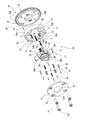
- the disassembled perspective view which shows the said valve timing control apparatus.
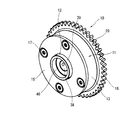
- the perspective view which shows the said valve timing control apparatus.
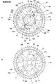
- the front view (A) and skeleton figure (B) which show the state which has the relative rotational position of the housing of the said valve timing control apparatus, and a vane rotor in the most retarded angle position.
- the front view (A) and skeleton figure (B) which show the state which has the said relative rotation position in an intermediate
- the front view (A) and skeleton figure (B) which show the state which has the said relative rotation position in the most advanced angle position.
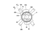
- the rear view which shows the vane rotor of the said valve timing control apparatus alone.
- FIG. 1 to 8 show an embodiment in which a valve timing control device according to the present invention is applied to an intake valve side of an internal combustion engine.
- valve timing control device 10 is coaxially and relatively rotatable in the radial direction of a housing 11 that is a rotating body that rotates together with a crankshaft (not shown) and a housing body 13 that is a cylindrical portion of the housing 11. And a vane rotor 12 as a rotating body that is arranged and rotates together with the camshaft 14.
- the housing 11 is coaxially arranged in front of the camshaft 14. As shown in FIG. 3, the housing 11 is arranged on both sides of the housing main body 13 and the housing main body 13 in the axial direction. It has the 1st side part and 2nd side part which obstruct
- the housing main body 13, the front plate 15 and the rear plate 16 are fastened and fixed together in the axial direction by four fixing bolts 17, and rotate integrally around the axis.
- the front plate 15 is in the form of a thin metal disk, and four first bolt holes 18 through which the fixing bolts 17 are inserted are formed through the outer periphery, and a first central hole 19 is formed through the center in the axial direction. ing.
- a seat surface 18A on which the head 17A of the fixing bolt 17 is seated is recessed.
- the rear plate 16 is in the form of a thin metal disk, and is integrally provided with a sprocket 20 having a large number of teeth on the outer periphery, and via a timing chain (not shown) wound around the sprocket 20 and the crankshaft. Driven by a crankshaft.
- Four rear screw holes 21 are formed in the outer peripheral portion of the rear plate 16 to be screwed with the male screw at the tip of the fixing bolt 17, and the front end portion of the camshaft 14 is rotated at the center of the shaft near the shaft center.
- a second central hole 22 is inserted therethrough, and around the second central hole 22, two lock holes 23 (23 ⁇ / b> A, 23 ⁇ / b> B) are located at symmetrical positions on the opposite sides of the shaft center. Is formed.
- the rear plate 16 is formed with a positioning pin hole 25 into which the positioning pin 24 is press-fitted and fixed.
- the positioning pin 24 is fitted into a positioning pin groove 26 formed in the outer periphery of the housing body 13, thereby assembling. Sometimes the rear plate 16 and the housing body 13 are positioned.
- the housing main body 13 is integrally formed in a cylindrical shape, for example, by sintered metal, and four shoes 28 (28A, 28B) are projected from the inner periphery of the outer peripheral cylindrical portion 27 inward in the radial direction.
- Each shoe 28 has a thick wall shape having the same axial dimension as that of the outer circumferential cylindrical portion 27, and has a so-called tapered trapezoidal shape in which the circumferential dimension gradually decreases inward in the radial direction.
- Each shoe 28 is formed with a second bolt hole 31 through which the fixing bolt 17 is inserted.
- each shoe 28 is configured to face the outer periphery of the rotor core 35 that forms the cylindrical shape of the vane rotor 12 with a slight gap, and is in part in sliding contact with the outer periphery of the rotor core 35.
- a first seal groove 32 is recessed at the tip of each shoe 28, and the first seal groove 32 is substantially co-conductive to seal the gap with the rotor core 35 by slidingly contacting the outer periphery of the rotor core 35.
- a letter-shaped first seal member 33 and a first leaf spring 34 that urges the first seal member 33 radially inward toward the outer periphery of the rotor core 35 are accommodated.
- the vane rotor 12 is integrally formed of, for example, sintered metal, and has a cylindrical central rotor core 35 and four vanes 36 (radially projecting radially outward from the outer periphery of the rotor core 35). 36A, 36B), and is coaxially fastened and fixed to the front end of the camshaft 14 which is hollow by a cam bolt 37 (see FIGS. 1 and 2), and rotates integrally with the camshaft 14. .
- the rotor core 35 is provided with a cylindrical portion 39 for accommodating the head portion 37A of the cam bolt 37 on the front end side when the third central hole 38 through which the cam bolt 37 passes is formed in the vicinity of the axial center of the rotor core 35. 39 penetrates the first central hole 19 of the front plate 15 so as to be relatively rotatable.
- the bottom surface of the cylindrical portion 39 where one end of the third central hole 38 opens functions as a seating surface 40 on which the head portion 37A of the cam bolt 37 is seated.
- the four vanes 36 are in the form of thin plates and are arranged at substantially equal intervals of about 90 degrees in the circumferential direction, and the radial length thereof is such that the tips of all the vanes 36 are located on the same circumference. Is set.
- the tip of each vane 36 is configured to face the inner periphery of the housing body 13 with a slight gap and to be in sliding contact with a part.
- a second seal groove 41 is recessed at the tip of each vane 36, and each second seal groove 41 seals a gap with the housing body 13 by slidingly contacting the inner periphery of the housing body 13.
- a substantially U-shaped second seal member 42 and a second leaf spring 43 that urges the second seal member 42 radially outward toward the inner periphery of the housing body 13 are accommodated.
- the working chamber 45 which is a space formed between the adjacent shoes 28 of the housing main body 13 by the vanes 36 slidably in contact with the inner periphery of the housing main body 13 in this way, is an advance working chamber 46 ( 46A, 46B) and the retarded working chamber 47 (47A, 47B).
- the first electromagnetic switching valve 51 as the valve timing control unit adjusts the hydraulic pressure of the working oil as the working fluid charged in the advance working chamber 46 and the retard working chamber 47.
- the relative rotational position of the housing 11 and the vane rotor 12 is changed, and consequently the valve timing of the intake valve driven by the camshaft 14 is controlled.
- the first electromagnetic switching valve 51 is a so-called three-position switching type hydraulic control valve, and the first solenoid 52 resists the spring force of the first return spring 53 by a duty signal from the control unit 50.
- the hydraulic pressure is switched by changing the position of.
- the first electromagnetic switching valve 51 includes a hydraulic pressure supply passage 56 to which the hydraulic oil pressurized by the oil pump 55 is supplied, a drain passage 58 for discharging the hydraulic oil to the oil pan 57 side, and the advance working chamber.
- An advance passage 59 communicating with 46 and a retard passage 60 communicating with the retard working chamber 47 are connected.
- the hydraulic pressure supply passage 56 includes a flow rate control valve 61 that controls (limits) the flow rate of the hydraulic oil supplied to the hydraulic pressure supply passage 56, and a filtration filter that removes foreign matter in the hydraulic oil. 62.
- the hydraulic pressure supply passage 56 is connected to the main gallery 63 of the internal combustion engine and a second electromagnetic switching valve 76 described later in addition to the first electromagnetic switching valve 51 described above.
- the advance passage 59 includes a first advance passage 59A formed in the camshaft 14 and a second advance passage 59B formed in the vane rotor 12. As shown in FIG. 8, a part of the second advance passage 59 ⁇ / b> B is recessed in the axial side surface of the vane rotor 12.
- the retard passage 60 includes a first retard passage 60A formed in the camshaft 14 and a second retard passage 60B formed in the vane rotor 12.
- the control unit 50 controls the relative rotation position of the housing and the vane rotor, and thus the valve timing of the intake valve, by controlling the duty ratio of the signal output to the first solenoid 52 according to the engine operating state.
- the hydraulic pressure supply passage 56 and the retard angle passage 60 communicate with each other, and the hydraulic pressure is supplied to the retard angle working chamber 47 through the hydraulic pressure supply passage 56 and the retard angle passage 60, while the advance angle passage 59 and the drain passage 58, the hydraulic oil in the advance working chamber 46 is discharged to the oil pan 57 side through the advance passage 59 and the drain passage 58, and the vane rotor 12 is retarded with respect to the housing 11 in the retard direction 87 ( (See FIGS. 5 to 7).
- the first spool 54 is in the advance position 66 moved to the left in FIG. 1 against the spring force of the first return spring 53.
- the hydraulic pressure supply passage 56 and the advance passage 59 communicate with each other, and the hydraulic pressure is supplied to the advance operation chamber 46 through the hydraulic supply passage 56 and the advance passage 59, while the retard passage 60 and the drain passage.
- the hydraulic oil in the retarding working chamber 47 is discharged to the oil pan 57 side through the retarding passage 60 and the drain passage 58, and the vane rotor 12 is advanced to the housing 11 in the advance direction 88 ( (See FIGS. 5 to 7).
- the first spool 54 is substantially in the intermediate holding position 67.
- both the advance passage 59 and the retard passage 60 are blocked, the hydraulic pressures of the advance working chamber 46 and the retard working chamber 47 are held, respectively, and the relative rotational positions of the housing 11 and the vane rotor 12 are the current positions. Held in position.
- the valve timing control device 10 of the present embodiment is provided with an intermediate lock mechanism that mechanically restrains and holds the relative rotational position of the housing 11 and the vane rotor 12 at a predetermined intermediate lock position (lock position).
- the intermediate lock mechanism is accommodated in two lock pin accommodating holes 70 formed in the vicinity of the large diameter portion 85 of the vane rotor 12 so as to be movable in the axial direction.
- Two lock pins 71 are provided as the lock members.
- Each lock pin 71 has a cylindrical base end portion 72 and a tip end portion 73 having a smaller diameter than the base end portion 72, and a pressure receiving surface 74 is provided at a step portion between the base end portion 72 and the tip end portion 73. Is formed.
- the two lock holes 71 are formed in such a manner that the end portions 73 of the two lock pins 71 protrude from the axial side surface of the vane rotor 12 and are recessed in the axial side surface of the housing body 13.
- the relative rotational positions of the vane rotor 12 and the housing 11 are constrained to a predetermined intermediate lock position by being respectively fitted to 23 (23A, 23B).
- the intermediate lock position at this time corresponds to a start valve timing suitable for starting the engine from the engine stop state, and is set to a relatively retarded position in consideration of startability as described later. (See FIG. 6).
- the intermediate lock mechanism includes a lock return spring 75 that urges the lock pin 71 in the protruding direction, and a second electromagnetic switching valve 76 as a lock control unit that changes the axial position of the lock pin 71. Yes.
- the second electromagnetic switching valve 76 is formed on the pressure receiving surface 74 of the lock pin 71 by the second solenoid 77 changing the position of the second spool 78 in response to a signal from the control unit 50.
- the operation of the lock pin 71 is controlled by switching the hydraulic pressure of the unlocking hydraulic chamber 80 that is faced.
- the second electromagnetic switching valve 76 is connected to the hydraulic pressure supply passage 56 and the drain passage 58 and the unlocking passage 81 communicating with the unlocking hydraulic chamber 80.
- the unlocking passage 81 includes a first unlocking passage 81A formed in the camshaft 14 and a second unlocking passage 81B formed in the vane rotor 12. As shown in FIG. 8, a part of the second unlocking passage 81 ⁇ / b> B is recessed in the axial side surface of the vane rotor 12.
- the distal end portions 73 of the two lock pins 71 are fitted into the lock holes 23 (23A, 23B), respectively, so that the relative rotational positions of the housing 11 and the vane rotor 12 are mechanically restricted.
- One of the two lock holes 23 is a long hole 23A that is long in the circumferential direction so that the tip portions 73 of the two lock pins 71 are smoothly fitted in the lock holes 23 (23A, 23B), respectively. (See FIG. 3).
- the lock hole 23A regulates the relative rotational position of the vane rotor 12 relative to the housing 11 with respect to the housing 11 when the lock pin 71 is fitted, and the lock hole 23B toward the retard angle side of the vane rotor 12 with respect to the housing 11. By restricting the relative rotation position, it is possible to hold the intermediate lock position. Further, since the lock hole 23A is formed as a long hole, the lock pin 71 is easily fitted into the lock hole 23B. Therefore, the lock pin 71 is fitted into the lock hole 23A and the relative rotation of the vane rotor 12 with respect to the housing 11 is restricted to some extent, thereby facilitating the fitting of the lock pin 71 into the lock hole 23B.
- the second solenoid 77 is energized to move the second spool 78 to the left in FIG.
- the unlocking passage 81 and the hydraulic pressure supply passage 56 communicate with each other, and the lock pin 71 moves in the anti-protruding direction against the spring force of the locking return spring 75 by the hydraulic pressure supplied to the unlocking hydraulic chamber 80 ( 1 and 2), the tip 73 of the lock pin 71 is housed inside the vane rotor 12, that is, the entire lock pin 71 is retracted from the housing 11.
- relative rotation between the housing 11 and the vane rotor 12 is allowed.
- FIG. 5A to 7A are front views of the housing 11 and the vane rotor 12 as viewed from the front side (left side in FIG. 3) with the front plate 15 removed
- FIG. B) is a skeleton diagram showing the lock hole 23 (23A, 23B), the advance passage 59, the retard passage 60, and the unlock passage 81 in a transparent manner
- FIG. 8 is a rear view of the vane rotor 12 as viewed from the rear side (right side in FIG. 3) alone.
- the cylindrical rotor core 35 of the vane rotor 12 includes two small-diameter portions 84 and two large-diameter portions 85 having larger radial dimensions than the small-diameter portions 84.
- the two small diameter portions 84 are provided at symmetrical positions that are approximately 180 degrees opposite to each other with the axis of the vane rotor 12 interposed therebetween.
- the two large diameter portions 85 are symmetrical positions that are approximately 180 degrees opposite to each other with the axis of the vane rotor 12 interposed therebetween. Is provided.
- the large-diameter portion 85 has a fan shape that partially protrudes radially outward with respect to the small-diameter portion 84, so that the lock hole 23 (23 ⁇ / b> A, 23 ⁇ / b> B) does not open to the working chamber 45. Regardless of the relative rotational position with respect to the vane rotor 12, the lock hole 23 (23A, 23B) extends in the circumferential direction so as to always cover.
- first vanes 36 ⁇ / b> A projecting radially outward from the outer periphery of the large diameter portion 85, and the remaining two are the small diameter portions 84.
- the second vane 36B protrudes radially outward from the outer periphery. Therefore, the first vane 36A has a shorter radial dimension than the second vane 36B.
- the two first vanes 36A are provided at symmetrical positions almost opposite to each other by 180 degrees across the axis of the vane rotor 12, and the two second vanes 36B are arranged at symmetrical positions almost opposite by 180 degrees across the axis of the vane rotor 12. Is provided. That is, the first vane 36A and the second vane 36B are alternately formed at approximately equal intervals of about 90 degrees in the circumferential direction.
- the second vane 36B extending radially outward from the small diameter portion 84 is inferior in rigidity because it has a longer radial dimension than the first vane 36A, all the second vanes 36B are shoeed as described later. Since it is set so as not to make contact with 28 in the circumferential direction, it is not necessary to ensure rigidity against contact in the circumferential direction. Therefore, the second vane 36B is set to have a shorter circumferential width than the first vane 36A, and in order to reduce the weight and increase the volume of the working chamber 45 while ensuring the sealing performance at the tip, the small diameter portion 84 is provided.
- the shape is such that the thickness in the circumferential direction gradually decreases as it goes inward in the radial direction, that is, the root portion connected to the small diameter portion 84 is thinned most in the circumferential direction.
- Two of the four shoes 28 provided on the housing main body 13 of the housing 11 are the first shoes 28A whose front ends are in sliding contact with the outer periphery of the large diameter portion 85, and the other two are the small diameter portions whose front ends are the same.
- the second shoe 28 ⁇ / b> B is in sliding contact with the outer periphery of 84. Accordingly, the first shoe 28A has a shorter radial dimension than the second shoe 28B.
- the two first shoes 28A are provided at symmetrical positions almost 180 degrees across the axis, and the two second shoes 28B are also arranged at symmetrical positions almost 180 degrees across the axis. That is, the first shoes 28A and the second shoes 28B are alternately formed at approximately equal intervals of about 90 degrees in the circumferential direction.
- the plurality of small-diameter portions 84, large-diameter portions 85, vanes 36, and shoes 28 are arranged symmetrically on the opposite sides with respect to the axial center, so that substantially the same shape and size can be achieved.
- the angular working chamber 46 and the retarding working chamber 47 are arranged symmetrically on the opposite sides with respect to the axial center, resulting in a well-balanced layout.
- the four working chambers 45 are constituted by two first working chambers 45A and two second working chambers 45B.
- the first working chamber 45A is operated by the first vane 36A and the first advance working chamber 46A and the first retarded working.
- the second working chamber 45B is partitioned into a second advance working chamber 46B and a second retard working chamber 47B by a second vane 36B.
- the first advance working chamber 46A is formed between the first vane 36A and the first shoe 28A
- the first retard working chamber 47B is formed between the first vane 36A and the second shoe 28B.
- the advance working chamber 46B is formed between the second vane 36B and the second shoe 28B
- the second retard working chamber 47B is formed between the second vane 36B and the first shoe 28A.
- the lock pin 71 and the accommodation hole 70 that accommodates the lock pin 71 are disposed at the position of the large diameter portion 85 on the radially inner side of the first vane 36 ⁇ / b> A in the axial direction of the vane rotor 12. That is, the lock pin 71 overlaps at least a portion with the large diameter portion 85 and at least the shaft center of the lock pin 71 overlaps the region 86 extending radially inward of the first vane 36A in the axial direction view of the vane rotor 12. Placed in position. More specifically, the center of the lock pin 71 and the accommodation hole 70 is located radially inward from the outer periphery of the large diameter portion 85 and radially outward from the inner periphery of the small diameter portion 84. The first vane 36A is located inside a region 86 extending radially inward.
- the lock pin 71 and the accommodation hole 70 are preferably arranged only inside the large diameter portion 85 without overlapping the small diameter portion 84.
- the large diameter portion 85 of the vane rotor 12 extends from the position of the first vane 36A to both sides in the circumferential direction, that is, extends from the position of the first vane 36A in the retarding direction 87 (first direction).
- the first large diameter portion 85A and the second large diameter portion 85B extending from the position of the first vane 36A in the advance angle direction 88 (second direction).
- the first large diameter portion 85A is set longer in the circumferential direction than the second large diameter portion 85B.
- the intermediate lock position used when starting the engine is slightly closer to the retarded angle within the relative rotatable range of the housing 11 and the vane rotor 12 for reasons such as securing internal EGR and improving startability. Has been placed. Therefore, the angle at which the vane rotor 12 can rotate relative to the housing 11 from the intermediate lock position in the retarding direction 87, that is, the movable range, is smaller than the movable range in the advanced angle direction 88. That is, in the present embodiment, the first large portion extending in the retarding direction 87 having a small movable range among the first and second large diameter portions 85A and 85B extending from the position of the first vane 36A to both sides in the circumferential direction. The diameter portion 85A is long in the circumferential direction, and the second large diameter portion 85B extending in the advance direction 88 having a large movable range is shortened in the circumferential direction.
- the tip of the first shoe 28A is set to be in sliding contact with the outer periphery of the first large diameter portion 85A that is long in the circumferential direction. That is, regardless of the relative rotational position of the housing 11 and the vane rotor 12, the first large-diameter portion 85A is arranged in the circumferential direction so that the tip outer periphery of the first large-diameter portion 85A and the tip inner periphery of the first shoe 28A are always in sliding contact.
- the first shoe 28A is set longer in the circumferential direction than the second shoe 28B.
- the first shoe 28 ⁇ / b> A is in sliding contact with the tip of the first large diameter portion 85 ⁇ / b> A at the position of the first seal member 33 accommodated in the first seal groove 32. Therefore, the position of the first seal groove 32 is arranged in the first shoe 28A near the first vane 36A, that is, near the advance direction 88. Therefore, as shown in FIG. 7, the circumferential length of the first large-diameter portion 85A is made as short as possible while the first large-diameter portion 85A and the first shoe 28A are slidably contacted even at the most advanced angle position.
- a portion of the small diameter portion 84 is left between the first large diameter portion 85A and the second vane 36B adjacent to the retarding direction 87 of the first large diameter portion 85A, so that the first large diameter portion A groove-like space 90 is secured between 85A and the second vane 36B.
- the second large-diameter portion 85B has a circumferential length as long as possible in a range that covers the lock hole 23 even when the relative rotation position is at the most retarded position. It is set short.
- the contact portion one place 91 and other vanes and shoes being separated from each other in the circumferential direction, it is easy to ensure the rigidity of the other vanes and shoes. Furthermore, if two or more contact points are set, there is a problem that the contact point is not stable due to dimensional variation or the like, but there is only one contact point as in this embodiment. By limiting to 91, such a problem does not occur.
- the circumferential side surface of the first shoe 28A is inclined with respect to the circumferential side surface of the first vane 36A so as to surely contact from the outer peripheral side and the root side of the first shoe 28A. It is considered as a surface.
- the vane rotor 12 is provided with the small-diameter portions 84 and the large-diameter portions 85 having larger radial dimensions than the small-diameter portions 84 alternately in the circumferential direction.
- the large diameter portion 85 extends in the circumferential direction so as to cover the lock hole 23 over the entire range of relative rotation with respect to the housing 11, and the first vane 36 ⁇ / b> A is radially outward from the outer periphery of the large diameter portion 85. Protruding.
- the lock pin 71 and its accommodation hole 70 are at least partly a large diameter portion as viewed in the axial direction of the vane rotor 12 as shown in FIGS. 85 and a region 86 whose axial center extends radially inward at a portion where the large diameter portion 85 extending in the circumferential direction of the first vane 36A and the first vane 36A extending in the radial direction intersect with each other. It is arranged at the overlapping position.
- the first vane 36A does not necessarily have to be in parallel.
- a portion intersecting with the large diameter portion 85 extending in the circumferential direction is radially inward. What is necessary is just to be arrange
- the large diameter is required to ensure a certain thickness around the accommodation hole 70.
- the radial dimension of the portion 85 must be increased to some extent.
- the first vane 36A is positioned radially outward of the accommodation hole 70 of the lock pin 71, so that the radial position of the accommodation hole 70 is closer to the outer periphery of the large diameter portion 85. Even if they are close to each other, a certain amount of thickness is secured around the accommodation hole 70 by the amount of the first vane 36A.
- the lock pin 71 and its accommodation hole 70 are arranged in the large diameter portion 85, and the radial dimension of the large diameter portion 85 is made as small as possible while ensuring a predetermined thickness around the accommodation portion 70. can do.
- the radial dimension of the first vane 36A extending radially outward from the outer periphery of the large-diameter portion 85 can be secured relatively long, and the pressure receiving area of the first vane 36A can be increased. 11 can improve the response of the relative rotation with the valve 11, and thus improve the response of the valve timing change. Further, since the pressure receiving area can be widened, the volume of the working chamber can be increased, and the holding performance of the working oil is improved.
- the vane rotor 12 can be reduced in size and weight, and the volume of the entire working chamber 45 with respect to the size of the housing 11 can be increased, so that the housing 11 can be reduced in size. . Therefore, the valve timing control device 10 can be reduced in size. Furthermore, if the volume of the working chamber is small, when air is mixed into the working chamber at the time of starting the engine or the like, there is a possibility that the air mixing ratio becomes high and the operation of the vane rotor becomes unstable. Thus, by enlarging the volume of the working chamber 45, the influence of the mixed air can be reduced and the operational stability can be improved.
- the movable range from the lock position is small.
- the first large-diameter portion 85A extending in the retard angle direction 87 is formed longer in the circumferential direction than the second large-diameter portion 85B extending in the advance angle direction 88 with a large movable range.
- the vane rotor 12 is more than the lock position 82. Even in the case of relative rotation in the advance direction 88, the lock hole 23 can be reliably closed by the first large diameter portion 85A.
- the circumferential dimension of the second large diameter portion 85B extending in the opposite direction (advance angle direction 88) to the retard direction 87 having a small movable range from the lock position 82 can be sufficiently shortened. The volume of the apparatus can be suppressed, and the above-described apparatus can be reduced in weight and size, and the influence of air can be reduced.
- the circumferential dimension of the second large-diameter portion 85B is sufficiently short within the range covering the lock hole 23 by adopting a configuration in which the shoe does not slide on the outer periphery of the second large-diameter portion 85B having a short circumferential dimension.
- the volume of the large diameter portion is reduced.
- the second vane 36B adjacent to the first vane 36A protrudes radially outward from the outer periphery of the small-diameter portion 84.
- a first advance working chamber 46A is formed between the first shoe 28A and the first vane 36A
- a second retard working chamber 47B is formed between the first shoe 28A and the second vane 36B.
- an advance working chamber is provided on the first vane 36A side
- a retard working chamber is provided on the second vane 36B side. Therefore, although the first advance working chamber 46A on the first vane 36A side does not face the small diameter portion 84, the second retard working chamber 47B on the second vane side faces a part of the small diameter portion 84.
- the volume of the second retardation working chamber 47B can be secured relatively large. Therefore, as described above, it is possible to effectively reduce the influence of air when supplying hydraulic oil to the retarded working chamber when the engine is started.
- a portion of the small diameter portion 84 remains between the second vane 36B and the first large diameter portion 85A. Therefore, a groove-like space 90 is formed radially outward of the small diameter portion 84 between the second vane 36B and the first large diameter portion 85A, and the volume of the retarding working chamber 47 is equivalent to this space 90. Can be secured greatly.
- the second vane 36B has small diameter portions 84 extending on both sides in the circumferential direction and is not connected to the large diameter portion 85, a sufficiently large pressure receiving area can be secured.
- the first vane 36A is provided at two positions opposite to each other across the axis of the vane rotor 12, and the second vane 36B is provided at two positions opposite to each other across the axis of the vane rotor 12. ing. That is, the first vane 36A and the second vane 36B have a well-balanced layout in which the first vane 36A and the second vane 36B are alternately arranged at equal intervals of about 90 degrees in the circumferential direction.
- the second shoe 28B adjacent to the first shoe 28A has its inner periphery facing the outer periphery of the small diameter portion 84 with a slight gap. That is, the second shoe 28 ⁇ / b> B is configured to be in sliding contact with the small diameter portion 84, not the large diameter portion 85.
- the second electromagnetic switching valve 76 serving as a lock control unit controls the hydraulic pressure supplied to the lock working chamber 45 facing the lock pin 71 (lock member), whereby the lock pin 71 is controlled. Change the axial position of.
- the second electromagnetic switching valve 76 is provided independently of the first electromagnetic switching valve 51 serving as a valve timing control unit. Therefore, the valve timing control by the first electromagnetic switching valve 51 and the control of the lock pin 71 by the second electromagnetic switching valve 76 can be controlled independently of each other according to the engine operating state.
- the lock pin 71 is not necessarily arranged so as to coincide with the radial center line 93 of the first vane 36A, and may be displaced in the circumferential direction to some extent in accordance with a layout request or the like.
- the lock pin 71 and its accommodation hole 70 are slightly offset in the retarding direction 87 with respect to the radial center line 93 of the first vane 36 ⁇ / b> A. Yes.
- the offset direction 88 is offset. Compared to the above, it is easy to ensure the thickness around the accommodation hole 70.
- the first vane 36 ⁇ / b> A that protrudes radially outward from the outer periphery of the large diameter portion 85 and the second that protrudes radially from the outer periphery of the small diameter portion 84.
- the vanes 36B are alternately arranged in the circumferential direction, and the small diameter portions 84 remain between the large diameter portions 85 and the second vanes 36B. That is, the large diameter portion 85 is not connected to both sides in the circumferential direction of the second vane 36B, and a part of the small diameter portion 84 remains. Therefore, it is possible to secure a relatively large volume of the working chamber 45, and it is possible to obtain effects such as lightening, downsizing, and reducing the influence of mixed air as described above.
- the small diameter portions 84 are connected to both sides in the circumferential direction of the second vane 36B, a sufficiently large pressure receiving area of the second vane 36B is ensured. Accordingly, it is possible to improve the responsiveness of changing the relative rotational position between the housing and the vane rotor, and thus changing the valve timing.
- the present invention has been described based on the specific embodiments, but the present invention is not limited to the above-described embodiments, and includes various changes and modifications.
- the present invention is applied to the intake valve side, but the present invention can also be applied to the exhaust valve side.
- either the front plate 15 or the rear plate 16 may be formed integrally with the housing body 13.
- lock hole 23 is provided in the rear plate 16, it may be provided in the front plate 15.
- valve timing control device for an internal combustion engine based on the embodiment described above, for example, the following modes can be considered.
- valve timing control device for an internal combustion engine, a cylindrical tubular portion, a first side portion that closes one axial end side of the tubular portion, an axial direction of the tubular portion, and the like.
- a housing having a second side portion closing the end side and rotating together with the crankshaft, a vane rotor arranged to be relatively rotatable radially inward of the cylindrical portion of the housing and rotating together with the camshaft, and the housing
- a working chamber formed between a plurality of shoes projecting radially inward from the inner periphery of the cylindrical portion and the shoe adjacent to the circumferential direction projecting radially outward from the outer periphery of the vane rotor.
- Element By tip is fitted has a lock hole for restraining the relative rotational position of the housing and the vane rotor.
- the vane rotor includes a small-diameter portion and a large-diameter portion having a larger radial dimension than the small-diameter portion, and the large-diameter portion covers the lock hole over the entire range of relative rotation between the housing and the vane rotor.
- the plurality of vanes includes a first vane that extends in a circumferential direction and protrudes radially outward from an outer periphery of the large-diameter portion, and the receiving hole is at least partially in an axial view of the vane rotor. While being provided in the large diameter portion, at least a part thereof is disposed at a position overlapping with a region in which the first vane extends radially inward.
- the large diameter portion includes a first large diameter portion extending in the first direction from the position of the first vane, a second large diameter portion extending in the second direction from the position of the first vane, The first large diameter portion is set longer in the circumferential direction than the second large diameter portion.
- the plurality of shoes include a first shoe whose tip is in sliding contact with the outer periphery of the first large diameter portion.
- the plurality of vanes includes a second vane adjacent to the first vane in the circumferential direction, and the second vane protrudes radially outward from the outer periphery of the small diameter portion, and the first vane
- One of the advance working chambers is formed between the shoe and the first vane
- one of the retard working chambers is formed between the first shoe and the second vane.
- a part of the small diameter part is left between the second vane and the large diameter part.
- the first vane is provided at two locations opposite to each other across the axis of the vane rotor
- the second vane is provided at two locations opposite to each other across the axis of the vane rotor. ing.
- the plurality of shoes include, for example, a second shoe that is adjacent to the first shoe in the circumferential direction and whose tip is in sliding contact with the small diameter portion.
- the circumferential side surface of one second large diameter portion becomes the circumferential side surface of one second shoe. It is set to abut.
- the shaft of the lock member is provided by controlling the pressure of the working fluid provided independently of the valve timing control unit and supplied to the lock working chamber facing the pressure receiving surface of the lock member.
- a lock control unit for changing the direction position is provided.
- the lock member is slightly offset in the first direction with respect to the radial center line of the first vane, for example.
- the shaft center of the lock member is disposed at a position overlapping the region where the first vane extends radially inward.
- valve timing control device for an internal combustion engine is coaxially and relatively rotatable inward in the radial direction of a housing that rotates with one of the crankshaft and the camshaft and a cylindrical portion of the housing.
- a vane rotor arranged and rotated together with the other of the crankshaft and the camshaft, a plurality of shoes projecting radially inward from the inner periphery of the cylindrical portion of the housing, and radially outward from the outer periphery of the vane rotor
- a plurality of vanes projecting and partitioning a working chamber formed between the shoes adjacent in the circumferential direction into a retard working chamber and an advanced working chamber, and provided in the receiving hole of the vane rotor so as to be movable in the axial direction.
- a small-diameter portion and a large-diameter portion having a larger radial dimension than the small-diameter portion are alternately provided in the circumferential direction, and the large-diameter portion covers the entire range of relative rotation between the housing and the vane rotor.
- the plurality of vanes extend in the circumferential direction so as to cover the lock hole, and the plurality of vanes are adjacent to the first vane in the circumferential direction, and the first vane projects radially outward from the outer periphery of the large-diameter portion.
- a second vane protruding radially outward from the outer periphery of the small diameter portion, and a part of the small diameter portion is left between the large diameter portion and the second vane.
Landscapes
- Engineering & Computer Science (AREA)
- Mechanical Engineering (AREA)
- General Engineering & Computer Science (AREA)
- Valve Device For Special Equipments (AREA)
Abstract
Description
Claims (13)
- 筒状をなす筒状部と、上記筒状部の軸方向一端側を閉塞する第1側部と、上記筒状部の軸方向他端側を閉塞する第2側部を有し、クランクシャフトとともに回転するハウジングと、
上記ハウジングの筒状部の径方向内方に相対回転可能に配置され、カムシャフトとともに回転するベーンロータと、
上記ハウジングの筒状部の内周より径方向内方へ突出する複数のシューと、
上記ベーンロータの外周より径方向外方へ突出し、周方向に隣り合う上記シューの間に形成される作動室を遅角作動室と進角作動室とに仕切る複数のベーンと、
上記ベーンロータの収容孔に軸方向に移動可能に設けられたロック部材と、
上記ハウジングの第1側部に軸方向に開口し、上記ロック部材の先端部が嵌合することにより上記ハウジングと上記ベーンロータの相対回転位置を拘束するロック孔と、を有し、
上記ベーンロータは、小径部と、この小径部よりも径方向寸法の大きい大径部を含み、
上記大径部は、上記ハウジングと上記ベーンロータの相対回転可能範囲の全域にわたって上記ロック孔を覆うように周方向に延在し、
上記複数のベーンは、上記大径部の外周より径方向外方へ突出する第1ベーンを含み、
上記収容孔は、上記ベーンロータの軸方向視で、少なくとも一部が上記大径部に設けられるとともに、少なくとも一部が上記第1ベーンを径方向内側に延長した領域と重なる位置に配置されている内燃機関のバルブタイミング制御装置。 - 上記ベーンロータが上記ハウジングに対して上記ロック位置から周方向に相対回転可能な可動範囲が小さい方向を第1方向とし、この第1方向と逆方向を第2方向とすると、
上記大径部は、上記第1ベーンの位置から上記第1方向へ延在する第1大径部と、上記第1ベーンの位置から上記第2方向へ延在する第2大径部と、を含み、
上記第1大径部が、上記第2大径部に比して、周方向に長く設定されている請求項1に記載の内燃機関のバルブタイミング制御装置。 - 上記複数のシューは、その先端が上記第1大径部の外周と摺接する第1シューを含んでいる請求項2に記載の内燃機関のバルブタイミング制御装置。
- 上記複数のベーンが、上記第1ベーンと周方向に隣り合う第2ベーンを含み、
この第2ベーンは、上記小径部の外周より径方向外方へ突出し、
上記第1シューと上記第1ベーンとの間に上記進角作動室の一つが形成され、
上記第1シューと上記第2ベーンとの間に上記遅角作動室の一つが形成されている請求項3に記載の内燃機関のバルブタイミング制御装置。 - 上記第2ベーンと上記大径部との間に上記小径部の一部が残されている請求項4に記載の内燃機関のバルブタイミング制御装置。
- 上記第1ベーンは、上記ベーンロータの軸心を挟んで互いに反対側の2箇所に設けられ、
上記第2ベーンは、上記ベーンロータの軸心を挟んで互いに反対側の2箇所に設けられている請求項5に記載の内燃機関のバルブタイミング制御装置。 - 上記複数のシューは、上記第1シューと周方向に隣り合い、その先端が上記小径部と摺接する第2シューを含んでいる請求項3に記載の内燃機関のバルブタイミング制御装置。
- 上記ベーンロータが上記ハウジングに対して最も上記第1方向に回転したときに、一つの上記第1ベーンの周方向側面が一つの上記第1シューの周方向側面に当接するように設定されている請求項3に記載の内燃機関のバルブタイミング制御装置。
- 上記ベーンロータが上記ハウジングに対して最も上記第2方向に回転したときに、一つの上記第2大径部の周方向側面が、一つの上記第2シューの周方向側面に当接するように設定されている請求項7に記載の内燃機関のバルブタイミング制御装置。
- 上記バルブタイミング制御部とは独立して設けられ、上記ロック部材の受圧面に面したロック用作動室に供給する作動流体の圧力を制御することにより、上記ロック部材の軸方向位置を変更するロック制御部を有する請求項1に記載の内燃機関のバルブタイミング制御装置。
- 上記ロック部材は、上記第1ベーンの径方向中心線に対し、上記第1方向に僅かにオフセットしている請求項2に記載の内燃機関のバルブタイミング制御装置。
- 上記ロック部材の軸心が、上記第1ベーンを径方向内側に延長した領域と重なる位置に配置されている請求項1に記載の内燃機関のバルブタイミング制御装置。
- クランクシャフトとカムシャフトの一方とともに回転するハウジングと、
このハウジングの筒状をなす筒状部の径方向内方に同軸上かつ相対回転可能に配置され、上記クランクシャフトと上記カムシャフトの他方とともに回転するベーンロータと、
上記ハウジングの筒状部の内周より径方向内方へ突出する複数のシューと、
上記ベーンロータの外周より径方向外方へ突出し、周方向に隣り合う上記シューの間に形成される作動室を遅角作動室と進角作動室とに仕切る複数のベーンと、
上記ベーンロータの収容孔に軸方向に移動可能に設けられたロック部材と、
上記ハウジング設けられ、上記ロック部材の先端部が嵌合するロック孔と、
を有し、
上記ベーンロータは、小径部と、この小径部よりも径方向寸法の大きい大径部と、が周方向に交互に設けられ、
上記大径部は、上記ハウジングと上記ベーンロータの相対回転可能範囲の全域にわたって上記ロック孔を覆うように周方向に延在し、
上記複数のベーンは、上記大径部の外周より径方向外方へ突出する第1ベーンと、上記第1ベーンと周方向に隣り合い、上記小径部の外周より径方向外方へ突出する第2ベーンと、を含み、
上記大径部と上記第2ベーンとの間に、上記小径部の一部が残されている内燃機関のバルブタイミング制御装置。
Priority Applications (4)
| Application Number | Priority Date | Filing Date | Title |
|---|---|---|---|
| US15/575,239 US10240494B2 (en) | 2015-05-20 | 2016-05-06 | Valve timing control device for internal combustion engine |
| JP2017519117A JP6404466B2 (ja) | 2015-05-20 | 2016-05-06 | 内燃機関のバルブタイミング制御装置 |
| CN201680029168.2A CN107614839A (zh) | 2015-05-20 | 2016-05-06 | 内燃机的气门正时控制装置 |
| DE112016002234.4T DE112016002234T5 (de) | 2015-05-20 | 2016-05-06 | Ventilsteuerungsvorrichtung für eine Verbrennungsmaschine |
Applications Claiming Priority (2)
| Application Number | Priority Date | Filing Date | Title |
|---|---|---|---|
| JP2015102336 | 2015-05-20 | ||
| JP2015-102336 | 2015-05-20 |
Publications (1)
| Publication Number | Publication Date |
|---|---|
| WO2016185918A1 true WO2016185918A1 (ja) | 2016-11-24 |
Family
ID=57320056
Family Applications (1)
| Application Number | Title | Priority Date | Filing Date |
|---|---|---|---|
| PCT/JP2016/063642 Ceased WO2016185918A1 (ja) | 2015-05-20 | 2016-05-06 | 内燃機関のバルブタイミング制御装置 |
Country Status (5)
| Country | Link |
|---|---|
| US (1) | US10240494B2 (ja) |
| JP (1) | JP6404466B2 (ja) |
| CN (1) | CN107614839A (ja) |
| DE (1) | DE112016002234T5 (ja) |
| WO (1) | WO2016185918A1 (ja) |
Cited By (1)
| Publication number | Priority date | Publication date | Assignee | Title |
|---|---|---|---|---|
| WO2020059313A1 (ja) * | 2018-09-19 | 2020-03-26 | 日立オートモティブシステムズ株式会社 | 内燃機関のバルブタイミング制御装置 |
Families Citing this family (1)
| Publication number | Priority date | Publication date | Assignee | Title |
|---|---|---|---|---|
| DE112018008200T5 (de) | 2018-12-14 | 2021-08-26 | Schaeffler Technologies AG & Co. KG | Nockenwellenphasenversteller |
Citations (3)
| Publication number | Priority date | Publication date | Assignee | Title |
|---|---|---|---|---|
| WO2011001702A1 (ja) * | 2009-07-01 | 2011-01-06 | アイシン精機株式会社 | 弁開閉時期制御装置 |
| JP2011202563A (ja) * | 2010-03-25 | 2011-10-13 | Hitachi Automotive Systems Ltd | 内燃機関のバルブタイミング制御装置 |
| JP2013087643A (ja) * | 2011-10-14 | 2013-05-13 | Hitachi Automotive Systems Ltd | 内燃機関のバルブタイミング制御装置 |
Family Cites Families (5)
| Publication number | Priority date | Publication date | Assignee | Title |
|---|---|---|---|---|
| JP4985729B2 (ja) * | 2008-09-11 | 2012-07-25 | 株式会社デンソー | バルブタイミング調整装置 |
| JP5358499B2 (ja) * | 2010-03-25 | 2013-12-04 | 日立オートモティブシステムズ株式会社 | 内燃機関のバルブタイミング制御装置及びその製造方法 |
| JP2012097594A (ja) * | 2010-10-29 | 2012-05-24 | Hitachi Automotive Systems Ltd | 内燃機関のバルブタイミング制御装置 |
| JP5763432B2 (ja) * | 2011-06-17 | 2015-08-12 | 日立オートモティブシステムズ株式会社 | 内燃機関のバルブタイミング制御装置 |
| JP5713823B2 (ja) * | 2011-07-08 | 2015-05-07 | 日立オートモティブシステムズ株式会社 | バルブタイミング制御装置に用いられる制御弁 |
-
2016
- 2016-05-06 WO PCT/JP2016/063642 patent/WO2016185918A1/ja not_active Ceased
- 2016-05-06 DE DE112016002234.4T patent/DE112016002234T5/de not_active Withdrawn
- 2016-05-06 CN CN201680029168.2A patent/CN107614839A/zh active Pending
- 2016-05-06 US US15/575,239 patent/US10240494B2/en active Active
- 2016-05-06 JP JP2017519117A patent/JP6404466B2/ja not_active Expired - Fee Related
Patent Citations (3)
| Publication number | Priority date | Publication date | Assignee | Title |
|---|---|---|---|---|
| WO2011001702A1 (ja) * | 2009-07-01 | 2011-01-06 | アイシン精機株式会社 | 弁開閉時期制御装置 |
| JP2011202563A (ja) * | 2010-03-25 | 2011-10-13 | Hitachi Automotive Systems Ltd | 内燃機関のバルブタイミング制御装置 |
| JP2013087643A (ja) * | 2011-10-14 | 2013-05-13 | Hitachi Automotive Systems Ltd | 内燃機関のバルブタイミング制御装置 |
Cited By (1)
| Publication number | Priority date | Publication date | Assignee | Title |
|---|---|---|---|---|
| WO2020059313A1 (ja) * | 2018-09-19 | 2020-03-26 | 日立オートモティブシステムズ株式会社 | 内燃機関のバルブタイミング制御装置 |
Also Published As
| Publication number | Publication date |
|---|---|
| US10240494B2 (en) | 2019-03-26 |
| US20180135470A1 (en) | 2018-05-17 |
| DE112016002234T5 (de) | 2018-02-15 |
| JP6404466B2 (ja) | 2018-10-10 |
| CN107614839A (zh) | 2018-01-19 |
| JPWO2016185918A1 (ja) | 2017-12-21 |
Similar Documents
| Publication | Publication Date | Title |
|---|---|---|
| JP5500350B2 (ja) | 弁開閉時期制御装置 | |
| US9133734B2 (en) | Valve timing control apparatus for internal combustion engine | |
| JP5403341B2 (ja) | 弁開閉時期制御装置 | |
| JPH1150820A (ja) | 内燃機関のバルブタイミング制御装置 | |
| US9476329B2 (en) | Camshaft phaser with a rotary valve spool positioned hydraulically | |
| JP6308163B2 (ja) | バルブタイミング調整装置 | |
| JP7264025B2 (ja) | バルブタイミング調整装置 | |
| KR101679016B1 (ko) | 내연기관의 밸브타이밍 조정장치 | |
| JP4001070B2 (ja) | 弁開閉時期制御装置 | |
| US9816408B2 (en) | Camshaft phaser | |
| JP6404466B2 (ja) | 内燃機関のバルブタイミング制御装置 | |
| EP1486644A1 (en) | Vane type phaser with locking pin | |
| JP7200914B2 (ja) | バルブタイミング調整装置 | |
| CN106032759B (zh) | 内燃机的气门正时控制装置 | |
| CN103485853A (zh) | 内燃机的可变气门装置 | |
| JPH09250310A (ja) | 内燃機関のバルブタイミング変更装置 | |
| JP2002276311A (ja) | バルブタイミング調整装置 | |
| JP4200920B2 (ja) | 弁開閉時期制御装置 | |
| US6935291B2 (en) | Variable valve timing controller | |
| US8171903B2 (en) | Intermediate lock pin type variable valve timing unit for vehicle and continuously variable valve timing device using the same | |
| JP6131665B2 (ja) | 弁開閉時期制御装置 | |
| JPH10159519A (ja) | 内燃機関のバルブタイミング制御装置 | |
| JPH112108A (ja) | 内燃機関の可変バルブタイミング機構 | |
| JP2017122419A (ja) | 弁開閉時期制御装置 | |
| JP5022327B2 (ja) | 内燃機関の可変バルブタイミング機構 |
Legal Events
| Date | Code | Title | Description |
|---|---|---|---|
| 121 | Ep: the epo has been informed by wipo that ep was designated in this application |
Ref document number: 16796312 Country of ref document: EP Kind code of ref document: A1 |
|
| ENP | Entry into the national phase |
Ref document number: 2017519117 Country of ref document: JP Kind code of ref document: A |
|
| WWE | Wipo information: entry into national phase |
Ref document number: 15575239 Country of ref document: US |
|
| WWE | Wipo information: entry into national phase |
Ref document number: 112016002234 Country of ref document: DE |
|
| 122 | Ep: pct application non-entry in european phase |
Ref document number: 16796312 Country of ref document: EP Kind code of ref document: A1 |