WO2016181868A1 - 磁気共鳴撮像装置、情報処理装置および高周波磁場シミング方法 - Google Patents
磁気共鳴撮像装置、情報処理装置および高周波磁場シミング方法 Download PDFInfo
- Publication number
- WO2016181868A1 WO2016181868A1 PCT/JP2016/063430 JP2016063430W WO2016181868A1 WO 2016181868 A1 WO2016181868 A1 WO 2016181868A1 JP 2016063430 W JP2016063430 W JP 2016063430W WO 2016181868 A1 WO2016181868 A1 WO 2016181868A1
- Authority
- WO
- WIPO (PCT)
- Prior art keywords
- parameter
- magnetic field
- frequency magnetic
- exclusion
- resonance imaging
- Prior art date
- Legal status (The legal status is an assumption and is not a legal conclusion. Google has not performed a legal analysis and makes no representation as to the accuracy of the status listed.)
- Ceased
Links
Images


Classifications
-
- A—HUMAN NECESSITIES
- A61—MEDICAL OR VETERINARY SCIENCE; HYGIENE
- A61B—DIAGNOSIS; SURGERY; IDENTIFICATION
- A61B5/00—Measuring for diagnostic purposes; Identification of persons
- A61B5/05—Detecting, measuring or recording for diagnosis by means of electric currents or magnetic fields; Measuring using microwaves or radio waves
- A61B5/055—Detecting, measuring or recording for diagnosis by means of electric currents or magnetic fields; Measuring using microwaves or radio waves involving electronic [EMR] or nuclear [NMR] magnetic resonance, e.g. magnetic resonance imaging
Definitions
- the present invention relates to a magnetic resonance imaging (MRI) technique, and more particularly to a high-frequency magnetic field irradiation technique for generating a rotating magnetic field that induces a magnetic resonance phenomenon.
- MRI magnetic resonance imaging
- the MRI apparatus is a medical image diagnostic apparatus that causes magnetic resonance to occur in nuclei in an arbitrary cross section that crosses the examination target, and obtains a tomographic image in the cross section from the generated magnetic resonance signal.
- a radio wave (Radio Frequency wave, hereinafter referred to as RF), which is a type of electromagnetic wave, is transmitted to the inspection object to excite the spins of the nuclei in the inspection object, and then receives a nuclear magnetic resonance signal generated by the nuclear spins.
- the inspection object is imaged.
- RF transmission to the inspection object is performed by the RF transmission coil, and reception of the nuclear magnetic resonance signal from the inspection object is performed by the RF reception coil.
- the wavelength of this RF is about 30 cm, which is approximately the same scale as the abdominal section, and the phase changes. Due to this phase change, the irradiation RF distribution and the spatial distribution of the rotating magnetic field generated by the RF and inducing a magnetic resonance phenomenon (hereinafter referred to as high frequency magnetic field distribution, B 1 ) become non-uniform, resulting in uneven brightness. Therefore, there is a need for a technique for reducing non-uniform distribution of the rotating magnetic field B 1 in RF irradiation performed by an ultrahigh magnetic field MRI apparatus.
- RF shimming As an RF irradiation method for reducing nonuniformity of the B 1 distribution.
- This is a technique of using a transmission coil having a plurality of channels and controlling the phase and amplitude of an RF pulse applied to each channel to reduce B 1 nonuniformity in the imaging region (see, for example, Patent Document 1). .
- the B 1 distribution of each channel Prior to the main imaging, the B 1 distribution of each channel is measured in advance, and an optimal RF pulse condition for reducing B 1 nonuniformity is calculated using the B 1 distribution.
- There has also been proposed a method of calculating an RF pulse condition that makes the B 1 distribution uniform with higher accuracy by changing the gradient magnetic field waveform see, for example, Patent Document 2.
- the amount of RF absorption (SAR (Specific Absorption Rate)) in the living body is regulated to fall within a predetermined range. Based on this regulation, a technique has been proposed in which RF pulse conditions are set in RF shimming so that the SAR absorbed by the entire living body (hereinafter, whole body SAR) is as small as possible (see, for example, Patent Document 3).
- SAR to be considered includes not only whole body SAR but also SAR that occurs locally in the living body (hereinafter referred to as local SAR). Similar to the whole body SAR, a limit value is set for the local SAR, and it is necessary to set an RF pulse condition such that the maximum local SAR is equal to or less than the limit value.
- the whole body SAR can be measured with a certain degree of accuracy, but the local SAR is difficult to measure. Therefore, the local SAR is mainly obtained by using numerical simulation. For example, SAR calculation is performed for a plurality of types of human body models (for example, Non-Patent Document 1). In addition, a method has been devised in which the whole body data of a patient is imaged before the actual imaging to create a human body model and the SAR of the patient is simulated (for example, Non-Patent Document 2).
- the whole body SAR is reduced, but the local SAR is not controlled.
- the local SAR distribution in the human body model is obtained by using numerical simulation and human body models having various shapes.
- the simulation is not performed on the body shape of the patient who is the subject at the time of imaging. For this reason, even when the local SAR distribution calculated in Non-Patent Document 1 is used during RF shimming, the local SAR of the subject to be imaged cannot be controlled.
- a whole body scan of a patient is performed to create a numerical human body model, and a simulation is performed for each patient.
- the present invention has been made in view of the above circumstances.
- the local SAR is suppressed to a predetermined limit value or less, and the optimum RF shimming is performed for each patient to be imaged.
- the purpose is to provide the technology to perform.
- a set of high-frequency magnetic field parameters (RF parameters) in which the local SAR is equal to or less than a predetermined limit value, for example, equal to or less than the upper limit value of regulation is specified as the usable RF parameter, and the range of the usable RF parameter Then, RF shimming is performed.
- Usable RF parameters include, for example, various types of human body models, simulations using all RF parameters that can be set by the MRI apparatus to be used, specifying RF parameters that are outside the predetermined range, and the remaining parameters It is specified as an RF parameter.
- the local SAR in an MRI apparatus using a transmission coil having a plurality of channels, can be suppressed to a predetermined limit value or less, and optimal RF shimming can be performed for each patient to be imaged.
- FIG. 1 It is a block diagram of the MRI apparatus of 1st embodiment.
- A is explanatory drawing for demonstrating the transmission coil of 1st embodiment.
- B is explanatory drawing for demonstrating the human body model of 1st embodiment.
- It is a functional block diagram of the computer of a first embodiment. It is a flowchart of the exclusion parameter determination process of 1st embodiment.
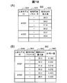
- A) is an explanatory diagram for explaining an example of the attribute database of the first embodiment
- (B) is an explanatory diagram for explaining an example of the calculation information database of the first embodiment.
- A) to (E) are explanatory diagrams for explaining the human body models prepared in the first embodiment.
- A)-(C) are explanatory drawings for explaining each human body model prepared in the first embodiment.
- (A) is explanatory drawing for demonstrating the relationship between distribution of the local SAR value of 1st embodiment, and a limit value.
- (B) is explanatory drawing for demonstrating distribution of the local SAR value after excluding the exclusion parameter of 1st embodiment.
- (A) And (B) is explanatory drawing for demonstrating the GUI example of 1st embodiment, respectively. It is explanatory drawing for demonstrating the concept of a principal component analysis.
- (A) to (G) are explanatory diagrams for explaining the result of the principal component analysis performed on the exclusion parameters of the first embodiment.
- (A)-(C) are explanatory drawings for demonstrating the exclusion parameter specific information generation method of 1st embodiment.
- (A) And (B) is explanatory drawing for demonstrating the modification of the exclusion parameter specific information generation method of 1st embodiment. It is a flowchart of the imaging process of 1st embodiment.
- (A) to (G) are explanatory diagrams for explaining another example of the result of the principal component analysis performed on the exclusion parameter of the modification of the present invention.
- (A) And (B) is explanatory drawing for demonstrating the modification of this invention.
- (A) And (B) is explanatory drawing for demonstrating the exclusion parameter specific information of the modification of this invention, respectively.
- (A) And (B) is explanatory drawing for demonstrating the exclusion parameter specific information of the modification of this invention, respectively. It is explanatory drawing for demonstrating the system configuration
- the value of the local SAR at the place where the local SAR is highest in the living body (human body model) when RF irradiation is performed with a certain RF parameter is defined as “maximum local SAR”.
- maximum local SAR is calculated over various high-frequency magnetic field conditions (RF parameters) or various human body models, the largest value among them is defined as “the maximum value of the maximum local SAR”.
- the RF parameter that provides the best B 1 uniformity is determined.
- the usable RF parameters are obtained in advance by excluding RF parameters in which the maximum value of the maximum local SAR is larger than the limit value.
- a numerical simulation is performed for all RF parameters using an assumed all-body model for each imaging region, and RF parameters to be excluded are determined.
- FIG. 1 is a block diagram of the MRI apparatus 100 of the present embodiment.
- the MRI apparatus 100 of the present embodiment includes a magnet 101 that generates a static magnetic field, a gradient coil 102 that generates a gradient magnetic field, a shim coil 112 that adjusts the static magnetic field uniformity, a sequencer 104, An RF transmission coil (transmission coil) 114 that irradiates (transmits) a high-frequency magnetic field (RF); an RF reception coil (reception coil) 115 that detects (receives) a nuclear magnetic resonance signal generated from the subject 103; A table 107 on which the subject 103 is placed, a gradient magnetic field power source 105, a high-frequency magnetic field generator 106, a receiver 108, a shim power source 113, and a computer 109 that controls each part of the MRI apparatus 100 and realizes imaging. .
- the gradient magnetic field coil 102 and the shim coil 112 are connected to the gradient magnetic field power source 105 and the shim power source 113, respectively.
- the transmission coil 114 and the reception coil 115 are connected to the high-frequency magnetic field generator 106 and the receiver 108, respectively.
- the sequencer 104 sends a command to the gradient magnetic field power source 105, the shim power source 113, and the high frequency magnetic field generator 106 according to an instruction from the computer 109 to generate a gradient magnetic field and RF, respectively.
- RF is irradiated (transmitted) to the subject 103 through the transmission coil 114.
- the nuclear magnetic resonance signal generated from the subject 103 by irradiating (transmitting) RF is detected (received) by the receiving coil 115 and detected by the receiver 108.
- a magnetic resonance frequency used as a reference for detection by the receiver 108 is set by the computer 109 via the sequencer 104.
- the detected signal is sent to the computer 109 through an A / D conversion circuit, where signal processing such as image reconstruction is performed.
- the result is displayed on the display device 110 connected to the computer 109.
- the detected signals and measurement conditions are stored in the storage device 111 connected to the computer 109 as necessary.
- the magnet 101, shim coil 112, and shim power supply 113 constitute a static magnetic field forming unit that forms a static magnetic field space.
- the gradient magnetic field coil 102 and the gradient magnetic field power source 105 constitute a gradient magnetic field application unit that applies a gradient magnetic field to the static magnetic field space.
- the transmission coil 114 and the high-frequency magnetic field generator 106 constitute a high-frequency magnetic field transmission unit that irradiates (transmits) a high-frequency magnetic field (RF) to the subject 103 arranged in the static magnetic field.
- the receiving coil 115 and the receiver 108 constitute a signal receiving unit that detects (receives) a nuclear magnetic resonance signal generated from the subject 103.
- the transmission coil 114 of the present embodiment is a multi-channel coil that includes a plurality of channels that independently transmit a high-frequency magnetic field (RF) to the subject 103.
- FIG. 2A shows an example of the transmission coil 114 of this embodiment.
- the transmission coil 114 is a four-channel (4ch) coil including four channels (114a, 114b, 114c, 114d) is illustrated.
- the amplitude and phase of RF transmitted from each channel (114a, 114b, 114c, 114d) are individually set by the computer 109.
- the high-frequency magnetic field generator 106 according to the present embodiment is independent of each channel via feeding points (117a, 117b, 117c, 117d) included in each channel (114a, 114b, 114c, 114d) in accordance with control from the computer 109.
- An RF waveform (RF pulse) is transmitted.
- reference numeral 116 denotes an RF shield.
- the computer 109 controls each unit of the MRI apparatus 100 to realize imaging.
- a static magnetic field shimming process for adjusting the uniformity of the static magnetic field in the imaging space and an RF shimming process for adjusting the uniformity of the B 1 distribution in the region of interest according to the purpose are further performed.
- the computer 109 collects image data according to the imaging condition setting unit 210 that sets the imaging conditions and the imaging conditions set by the imaging condition setting unit 210, as shown in FIG.
- An imaging unit 220 that performs imaging.
- the imaging condition setting unit 210 includes an imaging position setting unit 211 that sets an imaging position, a static magnetic field shimming unit 212 that performs static magnetic field shimming processing, and an RF shimming unit 213 that performs RF shimming processing.
- Each function realized by the computer 109 is realized by a CPU included in the computer 109 loading a program stored in advance in the storage device 111 to the memory and executing the program.
- ASIC Application Specific Integrated Circuit
- FPGA field-programmable gate array
- the imaging position setting unit 211 sets an imaging position (imaging cross section).
- the imaging section is set using a positioning image obtained by performing a scout scan or the like before performing the main imaging. For example, on the positioning image displayed on the display device 110, designation by the user is accepted, and the designated position is set as an imaging section.
- an imaging cross section a predetermined position may be automatically set for each part, using a feature point on the positioning image as a clue. Note that the region of the subject 103 on the imaging section is referred to as an imaging region.
- the static magnetic field shimming unit 212 measures the static magnetic field distribution and performs adjustment so that the static magnetic field is as uniform as possible. The adjustment is performed by operating the shim coil 112 via the shim power supply 113. If it is not necessary to adjust the uniformity of the static magnetic field, the static magnetic field shimming process may not be performed. Further, the static magnetic field shimming unit 212, the shim power source 113, and the shim coil 112 may not be provided.
- the RF shimming unit 213 of the present embodiment converts a transmission high-frequency magnetic field parameter (transmission RF parameter), which is a parameter (RF parameter) of a high-frequency magnetic field transmitted from each channel of the transmission coil 114, into a high-frequency magnetic field distribution (ROI) in a region of interest (ROI). decide to optimize the B 1 distribution). For example, it is determined that the nonuniformity of the B 1 distribution is corrected.
- the RF shimming unit 213 determines an optimum RF parameter that provides the best uniformity of the B 1 distribution for each imaging or for each subject 103.
- the RF parameter to be determined is at least one of the amplitude and phase of the RF transmitted from each channel of the transmission coil 114.
- the RF shimming unit 213 considers the local SAR when determining the optimum RF parameter.
- local SAR has regulations that consider the safety of living bodies.
- the RF shimming unit 213 determines an optimum RF parameter as a transmission RF parameter in a range where the local SAR does not exceed a limit value determined in consideration of a restriction value (upper limit value) during RF shimming.
- the RF shimming unit 213 of the present embodiment includes an exclusion parameter determination unit 214 that determines information for specifying a range of RF parameters to be excluded (exclusion parameter), and the MRI apparatus 100.
- RF shimming is performed in the RF parameter group (available RF parameters) obtained by excluding the excluded RF parameters determined by the excluded parameter determining unit 214 from the RF parameters that can be set to
- an RF parameter determination unit 215 that determines a RF parameter as a transmission RF parameter.
- the exclusion parameter determination unit 214 receives a threshold value input used when determining an exclusion parameter, and a human body model database that registers the human body model used when the exclusion parameter determination unit 214 determines an exclusion parameter.
- Human body model DB 300 is constructed on the storage device 111, for example.
- the exclusion parameter determination unit 214 of the present embodiment determines an exclusion parameter that is an RF parameter to be excluded in the RF shimming process.
- the exclusion parameter of the present embodiment is a high-frequency magnetic field parameter that may cause the local specific absorption rate (SAR) to become larger than a predetermined limit value when RF is transmitted by applying the parameter.
- SAR local specific absorption rate
- the limit value for example, an upper limit value (limit value) such as a safety standard value defined by the IEC (International Electrotechnical Commission) standard is used.
- the exclusion parameter determination unit 214 of the present embodiment uses various types of human body models prepared in advance, calculates a local SAR for each settable RF parameter by simulation, and excludes an RF parameter whose local SAR exceeds the limit value. Determine as a parameter.
- the exclusion parameters of the present embodiment include all human body models registered in a human body model database (human body model DB 300) prepared in advance and all settable parameters that are high-frequency magnetic field parameters that can be set by the MRI apparatus 100. , Are determined by simulation.
- the exclusion parameter is a settable parameter whose local specific absorption rate (SAR) obtained by the simulation is larger than the limit value.
- This limit value is set by the user via the receiving unit 216.
- the limit value may be registered in advance in the MRI apparatus 100.
- the exclusion parameter determination unit 214 performs a principal component analysis on the determined exclusion parameter, and outputs the result as information (exclusion parameter identification information) for identifying the exclusion parameter.
- exclusion parameter determination processing by the exclusion parameter determination unit 214 of the present embodiment will be described according to the processing flow of FIG.
- the exclusion parameter determination process by the exclusion parameter determination unit 214 is performed before actual imaging is performed. For example, it is performed when the MRI apparatus 100 is shipped, installed, or adjusted.
- Step S1101 First, the exclusion parameter determination unit 214 performs a local SAR calculation simulation that is a simulation for calculating a local SAR by changing the RF parameter (settable parameter) for each human body model. Then, for each human body model, the maximum local SAR of the total number of imaging slices per unit time is calculated.
- the local SAR calculation simulation is performed by modeling the four-channel transmission coil 114 shown in FIG. 2 (A) and placing a numerical human body model (human body model 130) shown in FIG. 2 (B), for example.
- the frequency of the RF to be transmitted is set to 128 MHz, assuming a 3T MRI apparatus, for example.
- the voltage of the sine waveform shown in the following formula (1) is fed to the feeding points (117a, 117b, 117c, 117d) of each channel (114a, 114b, 114c, 114d).
- A1 and ⁇ 1 are the amplitude and phase of the sine waveform voltage supplied to the feeding point 117a of the channel 114a, respectively.
- A2 and ⁇ 2 are the same amplitude and phase supplied to the feeding point 117b of the channel 114b, respectively.
- A3 and ⁇ 3 Are the same amplitude and phase supplied to the feeding point 117c of the channel 114c, and A4 and ⁇ 4 are the amplitude and phase supplied to the feeding point 117d of the channel 114d, respectively.
- the settable parameters are all combinations of all settable A1, all A2, all A3, all A4, all ⁇ 1, all ⁇ 2, all ⁇ 3, and all ⁇ 4.
- the local SAR is defined by the SAR value of each coordinate in the three-dimensional space of each human body model 130.
- the exclusion parameter determination unit 214 of the present embodiment calculates the SAR distribution for each human body model 130 using each settable parameter to obtain the SAR value of each coordinate, and the human body model 130 based on the settable parameter. Get the maximum local SAR.
- the SAR distribution (SAR dis ) when irradiated with the RF shown in the above formula (1) is the density ⁇ and conductivity ⁇ of the subject 103 (here, the human body model 130), and the electric field distribution of each channel.
- the RF parameters (amplitude and phase) of each channel it is expressed by the following equation (2).
- E1, E2, E3, and E4 are electric field distributions of the respective channels (114a, 114b, 114c, and 114d) at the time of outputting a certain reference, and r indicates a spatial coordinate.
- the exclusion parameter determination unit 214 needs to calculate the maximum local SAR of the total number of imaging slices per unit time in order to determine whether or not to exclude.
- imaging is performed in accordance with a predetermined imaging sequence, and the number of RFs applied per unit time and the number of imaging slices are different for each imaging sequence.
- the exclusion parameter determination unit 214 of the present embodiment calculates the maximum local SAR by a method that does not depend on the number of RF application times per unit time and the number of imaging slices, which differ depending on the imaging sequence. That is, a value corresponding to the maximum local SAR of the total number of imaging slices per unit time is calculated using the whole body SAR by one RF and a predetermined limit value of the whole body SAR.
- a whole body SAR (WholeBodySAR) using one RF can be obtained, for example, by calculating the sum of local SARs in all space coordinates. Therefore, it is expressed by the following formula (3) using the simulation result.
- the maximum local SAR (LocalSAR_max) by one RF is, for example, the maximum value of the local SARs in all space coordinates obtained by the simulation, and is expressed by the following formula (4).
- the exclusion parameter determination unit 214 of the present embodiment takes a product of a predetermined upper limit value of the whole body SAR of the human body model 130 and the Local / WBSAR obtained by the equation (5), so that each human body model 130 To obtain the upper limit of the local SAR. This is a value corresponding to the maximum local SAR of the total number of imaging slices per unit time.
- the calculation result is stored, for example, in the storage device 111 as the maximum local SAR.
- the maximum local SAR per unit time may be obtained by the following method.
- the local SAR value (SAR unit ) of the total number of imaging slices per unit time is expressed by the following equation (6).
- the number n of RF pulses applied per unit time and the number m of imaging slices are determined in advance as described above. For example, when the most frequently used imaging sequence is specified in advance, the number n of application and the number m of the imaging sequence may be used.
- the exclusion parameter determination unit 214 calculates the above equation (6) using all the settable parameters for each human body model 130, and the unit at each coordinate in the whole body three-dimensional space of the human body model 130.
- the local SAR of the total number of imaging slices per time is calculated.
- a local SAR value (maximum local SAR) at a place where the local SAR is highest in the human body model 130 is calculated. Also in this case, the calculation result is stored in the storage device 111, for example.
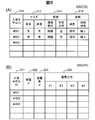
- FIG. 5A and FIG. 5B show an example of the human body model DB 300.
- the human body model DB 300 includes an attribute database 310 that stores a human body model ID 311 corresponding to the characteristics of the human body model for each human body model 130 prepared, and a density corresponding to each human body model ID 311.
- a calculation information database 320 in which information necessary for calculation such as distribution ⁇ , conductivity distribution ⁇ , and electric field distribution (E1, E2, E3, E4) for each channel is stored.
- the density distribution ⁇ , the conductivity distribution ⁇ , and the electric field distribution for each channel (E1, E2, E3, E4) are stored for each spatial coordinate in the human body model 130.
- information for identifying each human body model 130 is stored.
- information such as the human body size 312, the human body arrangement 313, and the human body posture 314 is stored as information for specifying the human body model 130.
- the human body size 312 registers height and weight
- the human body arrangement 313 registers, for example, the imaging position and the left-right direction
- the human body posture 314 registers, for example, the orientation and limb state.
- Each human body model is given a human body model ID 311.
- large, medium, and small are registered as information registered as height and weight.
- the imaging part for example, a head, a neck, a leg, an ankle, and the like are registered.
- the left-right direction for example, middle, left off center (left), right off center (right), and the like are registered.
- the orientation for example, supine (upward), prone, etc. are registered.
- the limb state for example, arms raised (above arms), arms lowered, arms bent, etc. are registered.
- 114 is a transmission coil as mentioned above.
- FIG. 6A shows a human body model 131 having a small height and weight
- FIG. 6B shows a human body model 132 having both a height and a weight
- FIG. 6D is a thin human model 134 with a large height and a small weight, so to speak
- FIG. 6E has a large height and a large weight.
- the information registered as height and weight is determined so as to cover, for example, the lean type and the obese type from the infant size to the adult size.
- the size of the prepared human body model 130 is not limited to these.
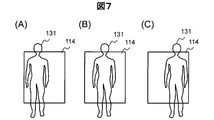
- FIG. 7A to 7C show examples of the arrangement of the human body model 130 in the left-right direction.
- FIG. 7A is an arrangement example in which, for example, the human body model 131 is arranged off-center on the right side with respect to the transmission coil 114
- FIG. 7B is an arrangement example in which the human body model 131 is arranged in the center of the transmission coil 114.
- FIG. 7C shows an arrangement example in which the human body model 131 is arranged off-center on the left side with respect to the transmission coil 114.
- calculation information database 320 calculation information for each human body model 130 specified by each attribute information is registered in association with the human body model ID 311.
- density ⁇ and conductivity ⁇ are physical property values for each type of tissue (fat, muscle, bone, etc.).
- the electric field distribution (E1, E2, E3, E4) for each channel is a reference phase and amplitude (referred to as a reference phase and a reference amplitude, respectively) at the time of imaging one slice in various human body models. For example, a value when a high frequency magnetic field is irradiated from each channel once per unit time is held. For example, the reference phase is 0 degree and the reference amplitude is 1. The value of the electric field distribution is obtained for each human body model 130 by simulation or actual measurement.
- Step S1102 the exclusion parameter determination unit 214 determines the maximum value of each calculated maximum local SAR value (maximum value of the maximum local SAR).
- the maximum value of the maximum local SAR is calculated in order to determine whether there is a settable parameter that becomes a local SAR value exceeding the limit value.
- the exclusion parameter determination unit 214 sets the largest value among all settable RF parameters and the maximum local SAR of the whole human body model 130 as the maximum value of the maximum local SAR.
- Step S1103 the exclusion parameter determination unit 214 compares the maximum value of the maximum local SAR with a predetermined limit value. This limit value is set by the user, for example. The accepting unit 216 accepts this limit value setting.
- the threshold value reception process by the reception unit 216 of the present embodiment will be described.
- the above limit value is accepted as the threshold value.
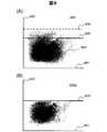
- the distribution of local SAR values calculated by local SAR simulation is shown in FIG.
- the horizontal axis is an index value (B 1 uniformity) 401 indicating the uniformity of the B 1 distribution
- the vertical axis is the local SAR value 402.
- a black point 403 indicates a coordinate point specified by the B 1 uniformity and the local SAR value in each imaging condition.
- the broken line 404 is a line indicating the maximum value of the local SAR obtained by the local SAR simulation
- the solid line 405 is a limit value.
- the exclusion parameter determination unit 214 of this embodiment determines an RF parameter (a settable parameter) having a local SAR value larger than the solid line 405 as an exclusion parameter.
- the receiving unit 216 of the present embodiment receives a limit value that is the position of the solid line 405 from the user.
- the accepting unit 216 displays the GUI 410 and / or 420 shown in FIG. 9A and FIG. 9B on the display device 110, and accepts the limit value via the GUI 410, 420.
- the GUI 410 includes a reception box 411 that receives an input of a limit value (local SAR limit value) from the user.
- the reception box 412 is a reception box that receives the B 1 uniformity threshold of the second embodiment.
- the user sets a limit value by directly inputting a numerical value via the reception box 411.
- the GUI 420 is an example of a screen that accepts setting of limit values from the user on a screen on which the local SAR simulation result is plotted. That is, the reception unit 216 receives an input of a limit value via a plot result of the local specific absorption rate (local SAR) for each settable parameter obtained by the local SAR simulation.
- local SAR local specific absorption rate
- the GUI 420 includes a display area 425 for displaying a local SAR simulation result, and a display box 421 for displaying a local SAR limit value.
- the user sets the local SAR limit value by inputting the local SAR limit value line 423 on the display area 425 while viewing the plot result.
- the reception unit 216 displays the received local SAR limit value as a numerical value on the display box 421. Note that it may be configured such that a numerical value is directly input via the display box 421 and the line 423 is displayed in the display area 425 according to the result. Alternatively, the local SAR limit value may be set by dragging the local SAR limit value line with a mouse or moving the local SAR limit value line with a keyboard key.
- the B 1 uniformity threshold line 424 and the display box 422 are configured to receive the B 1 uniformity threshold of the second embodiment.
- the limit value may be held in the storage device 111 in advance. In this case, for example, it may be determined based on the SAR upper limit value determined by IEC (International Electrotechnical Commission) or the like. For example, when the upper limit value of the local SAR of the abdomen is set to 20 W / kg, 20 W / kg is set as the limit value. In this case, the reception unit 216 may not be provided.
- IEC International Electrotechnical Commission
- the limit value may be set based on the values indicated in other documents.
- the limit value may be set based on safety-related data obtained by experiments using a temperature probe.
- the value may be set as a limit value. Further, considering the uncertainty included in the numerical simulation data used for safety evaluation and the experimental data, and considering the uncertainty as a safety margin, a stricter limit value may be set. Further, a limit value determined in consideration of safety may be used for each hospital.
- the limit value may be set at any timing as long as it is before the exclusion parameter determination process. For example, when setting the limit value before shipment, the user can set the limit value according to the shipping destination.
- Step S1104 As a result of the comparison, when the maximum value of the maximum local SAR exceeds the limit value, the exclusion parameter determination unit 214 sets the maximum local SAR value exceeding the limit value among the maximum local SAR values calculated in step S1101. The settable parameters stored in association with each other are extracted as exclusion parameters.
- a settable parameter for which the maximum local SAR value exceeding the limit value is calculated is used as an exclusion parameter regardless of which human body model 130 it is. For example, when there are 100,000 calculated maximum local SAR values, and among them, there are 1000 maximum local SAR values exceeding the limit value, these were obtained with different human body models even with the same settable parameters. Also included. In the present embodiment, the extraction is performed by paying attention only to the settable parameters. Therefore, the settable parameters to be extracted are 1000 or less.
- Step S1105) the exclusion parameter determination unit 214 performs principal component analysis on the settable parameters extracted as the exclusion parameters. This is for efficiently specifying the necessary and sufficient exclusion parameter range when using the exclusion parameter as a constraint condition in the RF parameter determination unit 215 described later.
- the exclusion parameter is specified in a range along a predetermined axis so that it can be easily used as a constraint condition in an RF parameter determination process by an RF parameter determination unit 215 described later.
- the axis is not set appropriately, many RF parameters other than the RF parameters that should be excluded are excluded, and the number of RF parameters that can be used in the RF parameter determination process is reduced. As a result, the degree of freedom in optimizing the B 1 uniformity for each patient decreases.
- principal axis conversion is performed in consideration of data dispersion. And the coordinate of each data is converted into the coordinate specified by the direction of each main axis.
- a thin line horizontal axis 501 and a thin line vertical axis 502 are axes of two parameters, respectively. These are referred to as an initial horizontal axis 501 and an initial vertical axis 502, respectively.
- a black dot 520 is an exclusion parameter. Hereinafter, it is referred to as an exclusion parameter distribution 520.
- the direction with the largest variance of the exclusion parameter is determined as the main direction, and the direction of the first main axis 511 is determined. Further, the second main shaft 512 is determined as a direction orthogonal to the main shaft 511.
- the range of the excluded parameter distribution 520 is specified by the coordinate system defined by the initial horizontal axis 501 and the initial vertical axis 502.
- the range specified by the maximum value and the minimum value in each axial direction is inside the region specified by the broken line 521 in FIG.
- the range specified by the maximum value and the minimum value in each axis direction is an area specified by the one-dot chain line 522 in FIG. Inside.
- a narrower region can be specified as compared with the case of using the initial coordinate system. That is, the minimum necessary exclusion parameter can be designated, and the necessary and sufficient exclusion parameter range can be designated most efficiently.
- the 4-channel transmission coil 114 is used, and the amplitude and phase of the RF to be irradiated from each are determined. Therefore, the number of parameters is eight. Therefore, as a result of performing the principal component analysis on the exclusion parameter, eight principal axes are specified.
- each axis The initial component of each axis is xi (i is an integer from 1 to 8), the first principal axis component after principal component analysis is u1, and the remaining seven principal axis components are ui (i is 2 to 8).
- the principal component analysis result is expressed by the following equation (7). Note that xi with an overline is an initial average value of each axis component, and rij (j is an integer from 1 to 8) is a coefficient obtained by principal axis conversion.
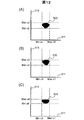
- FIGS. 11 (A) to 11 (G) Actual results of local SAR simulation and principal component analysis are shown in FIGS. 11 (A) to 11 (G).
- the main axis 511 (component u1) is represented on the horizontal axis
- the main axes 512 (component u2), 513 (component u3), 514 (component u4), 515 (component u5), 516 (component u6), and 517, respectively.
- Component u7), 518 (component u8) is the vertical axis.
- FIG. 11A shows the relationship between the components u1 and u2
- FIG. 11B shows the relationship between u1 and u3
- FIG. 11C shows the relationship between u1 and u4.
- 11D shows the relationship between u1 and u5
- FIG. 11E shows the relationship between u1 and u6
- FIG. 11F shows the relationship between u1 and u7.
- 11 (G) shows the relationship between u1 and u8, respectively.
- the dispersion in the direction of the component u1 is the largest, and the dispersion becomes smaller as u2 and u3.
- Step S1106 After performing the principal component analysis, the exclusion parameter determination unit 214 determines the exclusion parameter range using the result.
- each axis is referred to as its component, such as the main axis 511 being referred to as the u1 axis.
- the exclusion parameter determination unit 214 of the present embodiment uses the result of the principal component analysis, specifies the maximum value and the minimum value in each axial direction, and sets the range between them as the exclusion parameter range.
- the range in the u1 axis direction is determined as Min1 ⁇ u1 ⁇ Max1 using the maximum value (Max511) and the minimum value (Min511) in the u1 axis direction.
- the range in the u2 axis direction uses the maximum value (Maxu2) and the minimum value (Min2) in the u2 axis direction
- the range in the u3 axis direction is the maximum value in the u3 axis direction (Min2 ⁇ u2 ⁇ Maxu2).
- the maximum range (Maxu4) and the minimum value (Min4) are used for the range in the u4 axis direction using the maximum value (Maxu4) and the minimum value (Min4) in the u4 axis direction using Minu3 ⁇ u3 ⁇ Maxu3. And decide respectively.
- a predetermined margin may be provided when determining the exclusion parameter range.
- the determination method in this case will be described with reference to FIGS. 13 (A) and 13 (B).
- a margin 531 is set for a maximum value and a minimum value in each axis direction of the exclusion parameter distribution 520, and a exclusion parameter range is set.
- the margin 531 may be determined based on, for example, the uncertainty at the time of calculating the local SAR by simulation, or may be determined as a certain constant.
- the range may be specified with an ellipse line 532 surrounding (including inside) the exclusion parameter distribution 520.
- the exclusion parameter range may be specified by, for example, the following expression (8) using a mathematical expression that specifies the elliptical line 532.
- a and b are predetermined constants.
- a quadratic term may be used in the expression for specifying the range in each axial direction.
- third-order or higher terms may be used.
- the exclusion parameter determination unit 214 of the present embodiment generates a determination result, that is, information for specifying each main axis and a range of exclusion parameters specified by the main axis as exclusion parameter specification information, and ends the processing.
- the generated exclusion parameter specifying information is stored in the storage device 111 or the like, for example.
- the exclusion parameter determination unit 214 performs principal component analysis on the exclusion parameter distribution 520, and uses the obtained exclusion parameter range in each axis direction as exclusion parameter specifying information. That is, the minimum value in the ui axis direction ⁇ ui ⁇ the maximum value in the ui axis direction is generated as exclusion parameter specifying information.
- the exclusion parameter specifying information output by the exclusion parameter determination unit 214 of the present embodiment is a range of exclusion parameters in each axial direction obtained as a result of principal component analysis of this exclusion parameter distribution.
- step S1103 if the maximum value of the maximum local SAR is less than or equal to the limit value, the exclusion parameter determination unit 214 generates information indicating that there is no exclusion parameter as exclusion parameter specifying information.
- FIG. 8B shows the distribution of local SAR values when the exclusion parameter range is determined by the above method and the simulation is performed under the same conditions as in FIG. 8A using the RF parameters after the exclusion parameter is removed. Indicates. As shown in the figure, it can be seen that the distribution of points below the limit value hardly changes, and only points above the limit value are removed.
- the RF parameter determination unit 215 includes an optimization index indicating the uniformity of the high-frequency magnetic field distribution (B 1 distribution) in the region of interest (ROI) specified by the value (B 1 value) of the high-frequency magnetic field,
- a transmission high-frequency magnetic field parameter is determined using information (exclusion parameter specifying information) that specifies an exclusion parameter that is a high-frequency magnetic field parameter to be excluded during magnetic field shimming (RF shimming).
- the RF parameter determination unit 215 of this embodiment uses the exclusion parameter specifying information created by the exclusion parameter determination unit 214 as a constraint condition, an optimization index as an objective function, and a high-frequency magnetic field that optimizes the objective function within the constraint condition.
- the parameter (RF parameter) is determined as the transmission high-frequency magnetic field parameter.
- the optimization metrics used as an objective function for example, there is an index U SD represented by the following formula (9).
- R is a spatial coordinate
- B 1 (r) is a B 1 distribution
- ⁇ (B 1 (r)) is a standard deviation of B 1 value
- m (B 1 (r)) is an average value of B 1.
- the optimization metrics U SD is the standard deviation which is normalized, as the optimization metrics U SD is small, variation in the values is small, is uniform.
- the optimization index is not limited to the index of the above formula (9).
- the RF parameter determination unit 215 uses the exclusion parameter specifying information, and the RF parameter (RF parameter) that makes the optimization index USD the smallest in the range of the RF parameter (usable parameter) obtained by excluding the exclusion parameter from the settable parameter. (Optimal solution) is calculated and determined as a transmission RF parameter.
- the function used as the objective function is not limited to the above optimization index.
- the value may be a whole body SAR value, a local SAR value, or a combination thereof.
- Calculation of optimal solutions for RF parameters covers solutions for optimization problems, eg steepest descent method, gradient method, Newton method, least square method, conjugate gradient method, linear programming, nonlinear programming, amplitude and phase values
- solutions for optimization problems eg steepest descent method, gradient method, Newton method, least square method, conjugate gradient method, linear programming, nonlinear programming, amplitude and phase values
- a method of calculating an optimal solution by changing the threshold may be used.
- a solution that minimizes the objective function may be obtained by comprehensively changing the amplitude and phase values.
- the value of the objective function is calculated by changing the values of the amplitude and the phase by 1 dB and 5 degrees, respectively, and the amplitude and the phase in the case of the minimum are obtained.
- the amplitude and phase may be obtained in the vicinity of the amplitude and phase values with the amount of change reduced.
- the initial values of the amplitude and phase when performing these solutions are stored in the storage device 111 in advance.
- the predicted value may be used as an initial value, and the amplitude and phase may be comprehensively changed only for the nearby values.
- the RF solution may be actually transmitted using all usable parameters, and the B 1 distribution in the imaging region may be actually measured to obtain the optimum solution.
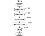
- FIG. 14 is a processing flow of the imaging process of the present embodiment.
- the imaging process is started upon receiving an instruction to start imaging from the user.
- the static magnetic field shimming process by the static magnetic field shimming unit 212 is omitted.
- the imaging condition setting unit 210 receives imaging condition settings from the user (step S1201). Then, according to the accepted imaging condition, the imaging position setting unit 211 sets an imaging position (step S1202).
- the RF shimming unit 213 performs RF shimming processing (step S1203).
- the RF parameter determination unit 215 determines the RF parameter that optimizes the uniformity in the ROI using the exclusion parameter specifying information created by the exclusion parameter determination unit 214 stored in the storage device 111 as a constraint condition, The transmission RF parameter is used.
- the RF shimming unit 213 reflects the determined transmission RF parameter in the imaging condition, and determines the imaging sequence (step S1204).
- the imaging unit 220 executes imaging according to the imaging sequence (step S1205).
- the exclusion parameter may be determined at any timing before imaging, such as before shipment or installation of the MRI apparatus 100.
- the exclusion parameter specifying information determined by the exclusion parameter determination unit 214 is held in the storage device 111, and the information is used at the time of imaging. Also good.
- the exclusion parameter specifying information may be stored in an external storage device capable of transmitting / receiving data to / from the computer 109 of the MRI apparatus 100.
- the MRI apparatus 100 accesses the storage device as necessary, extracts exclusion parameter specifying information, and uses it for processing.
- the computer 109 may not include the exclusion parameter determination unit 214.
- the MRI apparatus includes the transmission coil 114 having a plurality of channels that transmit a high-frequency magnetic field to the subject, and the transmission high-frequency magnetic field parameter that is a parameter of the high-frequency magnetic field transmitted from each channel.
- a high-frequency magnetic field shimming unit 213 that performs high-frequency magnetic field shimming to determine that the non-uniformity of the high-frequency magnetic field distribution in the region of interest is corrected, and an imaging unit 220 that performs imaging using the transmission high-frequency magnetic field parameters determined by the high-frequency magnetic field shimming unit 213.
- the high-frequency magnetic field shimming unit 213 includes an optimization index indicating the uniformity of the high-frequency magnetic field distribution in the region of interest specified by the value of the high-frequency magnetic field, a whole body specific absorption rate, and a local specific absorption rate And at least one of the high-frequency magnetic field parameters to be excluded during the high-frequency magnetic field shimming
- the transmission high-frequency magnetic field parameter is determined using information specifying an external parameter, and the local specific absorption rate is determined in advance when the high-frequency magnetic field is transmitted using the exclusion parameter as the transmission high-frequency magnetic field parameter.
- the high-frequency magnetic field parameter may be larger than the limit value.
- the exclusion parameters are obtained by simulation using all human body models registered in a human body model database prepared in advance and all settable parameters that are high-frequency magnetic field parameters that can be set by the magnetic resonance imaging apparatus. It may be determined.
- the exclusion parameter may be the settable parameter for which the local specific absorption rate obtained by the simulation is larger than the limit value.
- the information for specifying the exclusion parameter may be a range of the exclusion parameter in each axial direction obtained as a result of principal component analysis of the exclusion parameter distribution.
- the high-frequency magnetic field shimming unit 213 may include an exclusion parameter determination unit 214 that determines the exclusion parameter. And the said exclusion parameter determination part 214 may further be provided with the reception part 216 which receives the input of the threshold value used when determining the said exclusion parameter.
- the high-frequency magnetic field shimming unit 213 uses information specifying the exclusion parameter as a constraint condition, and uses at least one of the optimization index, the whole body specific absorption rate, and the local specific absorption rate as an objective function, and within the constraint condition
- the high-frequency magnetic field parameter that makes the objective function best may be determined as the transmission high-frequency magnetic field parameter.
- RF parameters exceeding the limit value are excluded in advance.
- this process is performed using principal component analysis, it is possible to efficiently specify necessary and sufficient RF parameters to be excluded as mathematical formulas suitable for the subsequent optimization process.
- the local SAR does not exceed the limit value when imaging is performed with the transmission RF parameters obtained by the RF shimming. Therefore, RF shimming can be performed easily and reliably within the limit value of the local SAR for each patient.
- variations of the human body model include those with different arrangements.
- the approach of calculating the local SAR of a patient to be actually imaged as in the prior art it is necessary to determine the position such as whether the actual patient is right or left.
- different human body models are prepared in consideration of all arrangements. Then, in all human body models, RF parameters with high local SAR are excluded. Therefore, there is no need for a system for determining whether the patient is on the right side or the left side.
- safety can be ensured from the viewpoint of local SAR for any patient who can actually image.
- a settable parameter in which the maximum value of the local SAR is larger than the limit value is determined as an exclusion parameter.
- a settable parameter in which the maximum value of the local SAR is larger than the limit value and a settable parameter whose uniformity does not satisfy a predetermined condition are also excluded parameters.
- the MRI apparatus 100 of the present embodiment basically has the same configuration as the MRI apparatus 100 of the first embodiment. However, since the requirements for excluding RF parameters are different as described above, the processing of the exclusion parameter determination unit 214 is different. Hereinafter, the present embodiment will be described focusing on the configuration different from the first embodiment.
- the exclusion parameter determination unit 214 of this embodiment determines an exclusion parameter that is a settable parameter to be excluded in the RF shimming process, as in the first embodiment.
- a settable parameter in which the maximum value of the local SAR exceeds a predetermined limit value and a settable parameter whose B 1 uniformity does not satisfy a predetermined condition are determined as exclusion parameters.
- a settable parameter in which the maximum value of the local SAR exceeds a predetermined limit value is the same as in the first embodiment. For this reason, description is abbreviate
- a settable parameter that is excluded because the maximum value of the local SAR exceeds a predetermined limit value is referred to as a local SAR exclusion parameter.
- the exclusion parameter determination unit 214 of the present embodiment also determines a settable parameter whose B 1 uniformity does not satisfy a predetermined condition using the B 1 distribution obtained by simulation. For example, as in the local SAR simulation, the B 1 distribution is calculated for all human models and all settable parameters. Then, using the calculation result, an index that can specify a predetermined B 1 uniformity, for example, the optimization index USD is calculated.
- the excluded parameter determination unit 214 determines a settable parameter whose index is greater than a predetermined index threshold (B 1 uniformity threshold) as an excluded parameter.
- a predetermined index threshold B 1 uniformity threshold
- an RF parameter that is excluded because the uniformity does not satisfy a predetermined condition is referred to as a uniformity exclusion parameter.
- the receiving unit 216 of this embodiment receives a B 1 uniformity threshold value.
- the GUI 410 displayed on the display device 110 by the reception unit 216 further includes a reception box 412 that receives the B 1 uniformity threshold, as shown in FIG. 9A.
- the GUI 420 further receives an input of the B 1 uniformity line 424 through the display area 425 as shown in FIG. 9B.
- the GUI 420 also includes a display box 422 that displays a numerical value corresponding to the accepted B 1 uniformity line 424.
- the B 1 uniformity threshold value may be received via the display box 422 and the value may be displayed as the line 424.
- the B 1 uniformity threshold is, for example, the B 1 uniformity required for satisfying the image quality evaluation considered necessary for diagnosis based on the image quality evaluation result and the data indicating the relationship between the B 1 uniformity. You may determine with a threshold value. It may also be set different values of B 1 uniformity for each imaging region as a threshold value. It may also be set different B 1 uniformity for each hospital as a threshold value. In addition, when using an imaging method that performs fat suppression, if the B 1 uniformity that enables fat suppression sufficiently is known in advance, a value of B 1 uniformity that enables fat suppression is set as a threshold value. It is also good.
- the exclusion parameter determination unit 214 of the present embodiment performs principal component analysis on the union of the local SAR exclusion parameter and the uniformity exclusion parameter, and generates exclusion parameter specifying information.
- an optimal RF parameter is determined using two constraint conditions, that is, a constraint condition based on the local SAR exclusion parameter range and a constraint condition based on the uniformity exclusion parameter.
- a uniformity exclusion parameter may be determined, and a simulation for specifying the local SAR exclusion parameter may be performed only for the remaining RF parameters. Conversely, the local SAR exclusion parameter may be determined, the B 1 uniformity may be calculated only for the remaining RF parameters, and the uniformity exclusion parameter may be determined.
- the exclusion parameter determination unit 214 may not be provided if the exclusion parameter specifying information is held in advance.
- the MRI apparatus 100 of this embodiment includes the transmission coil 114, the high-frequency magnetic field shimming 213, and the imaging unit 220, as in the first embodiment.
- the exclusion parameter may further include the settable parameter in which an index value indicating the uniformity of the high-frequency magnetic field distribution obtained by the simulation is greater than a predetermined index threshold.
- the local SAR when imaging is performed using the transmission RF parameter obtained in the RF shimming, the local SAR does not exceed the limit value. Therefore, as in the first embodiment, RF shimming within the limit value of the local SAR can be performed easily and reliably for each patient.
- optimization is performed from among RF parameters in a range that realizes a predetermined uniformity. Therefore, it is possible to determine the optimum RF parameter with higher efficiency and high uniformity.
- the uniformity exclusion parameter may be determined by actual measurement. In this case, for a plurality of body-type subjects 103, RF transmission is performed using all settable parameters, and the B 1 distribution is measured. Then, for example, the index USD is calculated using the result, and the uniformity exclusion parameter is determined.
- a simulation value may be used to determine the local SAR exclusion parameter, and an actual measurement value of the patient may be used to determine the uniformity exclusion parameter.
- the exclusion parameter range is determined as one range for each main axis direction, but the present invention is not limited to this.
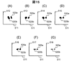
- the exclusion parameter range may be divided into a plurality of groups 520a and 520b in each axial direction, as shown in FIGS. 15 (A) to 15 (G).
- an exclusion parameter range may be specified for each group of principal component analysis results. That is, inequalities are created for the number of groups in the main axis direction divided into a plurality of groups.
- the reason for being divided into a plurality of groups in this manner is that a plurality of locations indicating the maximum local SAR value are generated in the human body model 130 in the local SAR simulation.
- the examples shown in FIGS. 15A to 15G are examples in which the maximum local SAR values are obtained at two locations, for example, in the abdomen and in the arm. In such a case, the feature of the RF parameter that increases the local SAR is different at each location, so the exclusion parameter distribution is divided into two groups.
- the exclusion parameter distribution may be divided into a plurality of groups, and the principal component analysis may be performed on each of the RF parameters belonging to each group to create exclusion parameter specifying information.
- a local SAR simulation is performed on the prepared whole human body model 130 using one or more presettable parameters, and the maximum local SAR value is obtained, and the human body having the maximum maximum local SAR value is obtained.
- the model 130 is determined as the worst model. Then, only the worst model may be configured to perform local SAR simulation for all settable parameters.
- the exclusion parameter determination unit 214 performs principal component analysis on the exclusion parameter based on the worst model, and generates exclusion parameter specifying information.
- the worst model may be specified in the human body model 130, and information for specifying the uniformity exclusion parameter range may be generated using only the worst model.
- a settable parameter for obtaining a local SAR value exceeding the limit value is used as an exclusion parameter regardless of the human body model 130.
- the determination unit of the exclusion parameter is not limited to this.
- the exclusion parameter may be determined for each human body model 130.
- the excluded parameter determination unit 214 performs a simulation for the whole human body model 130 and all the settable parameters, and sets a settable parameter for obtaining a local SAR value exceeding the limit value for each human body model 130 as an excluded parameter. Accordingly, the exclusion parameter specifying information in this case is created for each human body model 130.
- the exclusion parameter determination unit 214 stores exclusion parameter specifying information in association with information for specifying the human body model, for example, the human body model ID 311 for each human body model.
- the RF parameter determination unit 215 uses, as a constraint condition, exclusion parameter specifying information stored in association with the human body model 311 closest to the size, arrangement, and posture of the subject 103 to be imaged during actual imaging. Determine the optimal transmit RF parameters. That is, the high-frequency magnetic field shimming unit 213 uses the information (exclusion parameter specifying information) for specifying the exclusion parameter determined in association with the human body model closest to the subject 103 to be imaged as a constraint condition, the optimization index, the whole body ratio At least one of the absorption rate and the local specific absorption rate is set as an objective function, and a high-frequency magnetic field parameter that optimizes the objective function within the constraints is determined as a transmission high-frequency magnetic field parameter (transmission RF parameter).
- information specifying an exclusion parameter determined in association with the human body model closest to the subject 103 among human body models having a size (height or weight) larger than the subject 103 to be imaged may be used as a constraint condition. Good.
- the exclusion parameter specifying information may be generated in consideration of the B 1 uniformity as in the second embodiment.
- the minimum necessary RF parameter can be set as the exclusion parameter, and the degree of freedom during RF shimming during actual imaging is increased.
- an exclusion parameter may be determined for each imaging region instead of for each human body model 130, and exclusion parameter specifying information may be generated.
- the B 1 uniformity threshold value may also be determined for each imaging region.
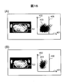
- an exclusion parameter may be determined for each ROI that may be set, and exclusion parameter specifying information may be generated.
- exclusion parameter specifying information may be generated. For example, as shown in FIGS. 16A and 16B, the relationship between the maximum value of the maximum local SAR and the B 1 uniformity depends on the position and size of the ROI to be set even in the same imaging region. Changes.
- the exclusion parameter identification unit 214 needs to identify the exclusion parameter and generate exclusion parameter identification information.
- the RF parameter determination unit 215 can search for an RF parameter that optimizes the objective function without any constraints.
- the exclusion parameter determination unit 214 extracts an RF parameter whose local SAR value is larger than the limit value, determines it as an exclusion parameter, and uses the range as exclusion parameter specifying information. It is not limited to this. Conversely, an RF parameter having a local SAR value equal to or less than the limit value may be extracted as a usable RF parameter, a principal component analysis may be performed on the extracted RF parameter, and the result may be stored as a constraint condition. .
- the exclusion parameter determination unit 214 creates exclusion parameter specifying information by performing principal component analysis on the exclusion parameter obtained from the simulation result.
- the exclusion parameter specifying information is not limited to the principal component analysis result. For example, it may be created as a database.
- the excluded parameter determination unit 214 creates a database in which usable parameters that are high-frequency magnetic field parameters obtained by excluding the excluded parameters from the settable parameters are registered as excluded parameter specifying information.
- the excluded parameter determination unit 214 of the present modification performs a local SAR simulation using the whole human body model 130 and all settable parameters, as in the first embodiment. Then, the maximum local SAR value for each settable parameter is obtained. The excluded parameter determination unit 214 sets a settable parameter in which the maximum value of the local SAR value is larger than the limit value as an excluded parameter. Then, the remaining settable parameters are made into a database (usable parameter DB) as usable parameters.
- a database usable parameter DB
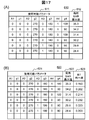
- FIG. 6 An example of the usable parameter DB 610 created at this time is shown in FIG. As shown in the figure, an available parameter 611 is registered in the available parameter DB 610. Note that the maximum value 612 of the maximum local SAR may be further registered for each usable parameter 611.
- the usable parameter DB 610 is created by the following method, for example.
- the RF parameter determination unit 215 uses the exclusion parameter identification information as a constraint condition and the optimization index as an objective function, and sets the objective function within the constraint condition during actual shooting, as in the first embodiment.
- the best RF parameter is determined as the transmission RF parameter.
- the RF parameter with the best B 1 uniformity is determined as the transmission RF parameter.
- the uniformity within the ROI may be calculated using a predetermined index for the whole human body model 130 and all the settable parameters by simulation.
- the usable parameter DB 620 includes, for each usable parameter 621, for example, the worst value (maximum value) among the values of the uniformity index by each human body model. ) 623 may be registered. Note that the maximum value 622 of the local SAR may be registered at the same time.
- the excluded parameter determination unit 214 tabulates all simulation results, that is, the maximum value of the local SAR and the maximum value of the uniformity index for each settable parameter as one record. Then, the records are sorted in ascending order or descending order by the maximum value of the local SAR, and only records where the maximum value of the local SAR is equal to or less than the limit value are extracted. Next, the extracted records are sorted in ascending or descending order according to the maximum value of the uniformity index, and only records whose maximum value of the uniformity index is equal to or less than the index threshold are extracted. And it is set as usable parameter DB620 using an extraction result.
- the RF parameter determination unit 215 searches for an RF parameter that has the best B 1 uniformity among the available parameters registered in the available parameter DB 620 at the time of actual photographing, and determines it as a transmission RF parameter. To do.
- a usable parameter DB may be created for each human body model.
- the maximum value of the local SAR is stored in each usable parameter for each human body model.
- An example of the usable parameter DB 630 in this case is shown in FIG.
- usable parameters 631 are registered in association with the human body model ID 634 that specifies the human body model.
- the local SAR maximum value 632 may also be registered.
- the RF parameter determination unit 215 specifies the human body model ID of the human body model closest to the subject 103 to be imaged among the human body models registered in the usable parameter DB 630 during actual imaging, and Among the usable parameters 631 registered in association with the human body model ID 634, an RF parameter having the best B 1 uniformity is searched for as a transmission RF parameter.
- the B 1 uniformity may be registered in the usable parameter DB at the same time.
- An example of the usable parameter DB 640 in this case is shown in FIG.
- the usable parameter 641 is registered in association with the human body model ID 644. At this time, the maximum value 642 of the local SAR and the B 1 uniformity 643 may also be registered.
- the RF parameter determination unit 215 is closest to the subject 103 to be imaged among the human body models registered in the usable parameter DB 640 at the time of actual imaging.
- the human body model ID of the human body model is specified, and among the usable parameters registered in association with the human body model ID 644, the usable parameter of the record in which the best B 1 uniformity 643 is registered is transmitted as RF. It is a parameter.
- the database (usable parameter DB) 640 is created for each human body model, and the database (usable parameter DB) indicates the uniformity of the high-frequency magnetic field distribution obtained by the simulation for each usable parameter.
- the high-frequency magnetic field shimming unit (RF shimming unit) 215 is registered in the database (usable parameter DB) 640 in association with the human body model closest to the subject 103 to be imaged.
- the usable parameter having the best index value is determined as the transmission high-frequency magnetic field parameter (transmission RF parameter).
- the 3T MRI apparatus and the 4-channel transmission coil have been described as examples, but the configuration of the MRI apparatus is not limited to this.
- a transmission coil having a higher magnetic field than 3T and a number of channels larger than 4 channels may be used.
- the case where the computer 109 included in the MRI apparatus 100 includes the imaging condition setting unit 210 has been described as an example.
- the construction location of the imaging condition setting unit 210 is not limited thereto.
- all or a part of the functions of the imaging condition setting unit 210 are the information processing apparatus 191 independent of the MRI apparatus 100 that can transmit and receive data to and from the computer 109 via, for example, the network 190. It may be built on top.
- the human body model DB 300 may be constructed not on the storage device 111 provided in the MRI apparatus 100 but on an independent storage device 192 accessible by the computer 109.
- 100 MRI apparatus, 101: magnet, 102: gradient coil, 103: subject, 104: sequencer, 105: gradient magnetic field power source, 106: high-frequency magnetic field generator, 107: table, 108: receiver, 109: calculator, 110: display device, 111: storage device, 112: shim coil, 113: shim power source, 114: transmission coil, 114a: channel, 114b: channel, 114c: channel, 114d: channel, 115: reception coil, 117a: feeding point, 117b: feeding point, 117c: feeding point, 117d: feeding point, 130: human body model, 131: human body model, 132: human body model, 134: human body model, 134: human body model, 135: human body model, 190: network, 191 : Information processing device, 192: Storage device, 210: Imaging Item setting unit, 211: imaging position setting unit, 212: static magnetic field shimming unit, 213: RF shimming unit, 214
Landscapes
- Health & Medical Sciences (AREA)
- Life Sciences & Earth Sciences (AREA)
- Physics & Mathematics (AREA)
- Nuclear Medicine, Radiotherapy & Molecular Imaging (AREA)
- Engineering & Computer Science (AREA)
- Medical Informatics (AREA)
- Biophysics (AREA)
- Pathology (AREA)
- High Energy & Nuclear Physics (AREA)
- Biomedical Technology (AREA)
- Heart & Thoracic Surgery (AREA)
- Radiology & Medical Imaging (AREA)
- Molecular Biology (AREA)
- Surgery (AREA)
- Animal Behavior & Ethology (AREA)
- General Health & Medical Sciences (AREA)
- Public Health (AREA)
- Veterinary Medicine (AREA)
- Magnetic Resonance Imaging Apparatus (AREA)
Applications Claiming Priority (2)
| Application Number | Priority Date | Filing Date | Title |
|---|---|---|---|
| JP2015-098838 | 2015-05-14 | ||
| JP2015098838A JP6408954B2 (ja) | 2015-05-14 | 2015-05-14 | 磁気共鳴撮像装置、情報処理装置および高周波磁場シミング方法 |
Publications (1)
| Publication Number | Publication Date |
|---|---|
| WO2016181868A1 true WO2016181868A1 (ja) | 2016-11-17 |
Family
ID=57249241
Family Applications (1)
| Application Number | Title | Priority Date | Filing Date |
|---|---|---|---|
| PCT/JP2016/063430 Ceased WO2016181868A1 (ja) | 2015-05-14 | 2016-04-28 | 磁気共鳴撮像装置、情報処理装置および高周波磁場シミング方法 |
Country Status (2)
| Country | Link |
|---|---|
| JP (1) | JP6408954B2 (enExample) |
| WO (1) | WO2016181868A1 (enExample) |
Families Citing this family (2)
| Publication number | Priority date | Publication date | Assignee | Title |
|---|---|---|---|---|
| JP6965073B2 (ja) * | 2017-09-19 | 2021-11-10 | キヤノンメディカルシステムズ株式会社 | 磁気共鳴イメージング装置 |
| JP7721264B2 (ja) * | 2020-12-07 | 2025-08-12 | キヤノンメディカルシステムズ株式会社 | 医用情報処理装置および医用情報処理方法 |
Citations (1)
| Publication number | Priority date | Publication date | Assignee | Title |
|---|---|---|---|---|
| WO2015029652A1 (ja) * | 2013-08-27 | 2015-03-05 | 株式会社日立メディコ | 磁気共鳴撮像装置および撮像パラメータ決定方法 |
Family Cites Families (3)
| Publication number | Priority date | Publication date | Assignee | Title |
|---|---|---|---|---|
| WO2013169368A1 (en) * | 2012-05-09 | 2013-11-14 | The General Hospital Corporation | System and method for local sar reduction in multislice parallel transmission magnetic resonance imaging using sar hopping between excitations |
| WO2014021172A1 (ja) * | 2012-08-03 | 2014-02-06 | 株式会社日立メディコ | 磁気共鳴撮像装置および高周波磁場条件決定方法 |
| BR112015008810A2 (pt) * | 2012-10-23 | 2017-07-04 | Koninklijke Philips Nv | sistema e método de imageamento por ressonância magnética |
-
2015
- 2015-05-14 JP JP2015098838A patent/JP6408954B2/ja active Active
-
2016
- 2016-04-28 WO PCT/JP2016/063430 patent/WO2016181868A1/ja not_active Ceased
Patent Citations (1)
| Publication number | Priority date | Publication date | Assignee | Title |
|---|---|---|---|---|
| WO2015029652A1 (ja) * | 2013-08-27 | 2015-03-05 | 株式会社日立メディコ | 磁気共鳴撮像装置および撮像パラメータ決定方法 |
Also Published As
| Publication number | Publication date |
|---|---|
| JP2016214277A (ja) | 2016-12-22 |
| JP6408954B2 (ja) | 2018-10-17 |
Similar Documents
| Publication | Publication Date | Title |
|---|---|---|
| US10241161B2 (en) | Magnetic resonance imaging device and imaging parameter determination method | |
| US10451701B2 (en) | Magnetic resonance imaging device, and determination method for high-frequency magnetic field conditions | |
| JP6133124B2 (ja) | 医療用撮像システムにおけるノイズ制御システム | |
| JPWO2014080781A1 (ja) | 磁気共鳴イメージング装置、及び、sarの予測方法 | |
| KR20150143329A (ko) | 자기 공명 영상화 방법 | |
| US20060197528A1 (en) | Method for controlling an RF transmission device, and MR apparatus and RF device for implementing the method | |
| US9513355B2 (en) | Controlling a magnetic resonance system | |
| US7535231B2 (en) | Method for adjustment of a shim device of a magnetic resonance apparatus | |
| US20160223632A1 (en) | Magnetic resonance imaging apparatus and magnetic resonance spectroscopic method using the same | |
| KR20160020897A (ko) | 자기 공명 영상 장치의 펄스 시퀀스 검증 방법 및 이를 위한 장치 | |
| WO2014034722A1 (ja) | 磁気共鳴イメージング装置及びその比吸収率の演算方法 | |
| JP6408954B2 (ja) | 磁気共鳴撮像装置、情報処理装置および高周波磁場シミング方法 | |
| JP6618988B2 (ja) | 磁気共鳴イメージング装置およびrfシミングパラメータの設定方法 | |
| JP6454157B2 (ja) | 磁気共鳴イメージング装置及びq値算出方法 | |
| JP2016214277A5 (enExample) | ||
| JP5797765B2 (ja) | 磁気共鳴撮像装置、高周波磁場照射方法およびプログラム | |
| US10788552B2 (en) | Method and control unit for operating a gradient coil device of an MRI system or another periodically stressed device | |
| JP6513493B2 (ja) | 磁気共鳴撮像装置 | |
| JP2022055893A (ja) | 磁気共鳴イメージング装置、被検体位置合わせ装置、および、被検体位置合わせ方法 | |
| JP6527138B2 (ja) | 核磁気共鳴撮像装置およびrfシミング方法 | |
| JP2015181891A (ja) | 磁気共鳴撮像装置 | |
| JP6715165B2 (ja) | 磁気共鳴イメージング装置及び画像処理方法 |
Legal Events
| Date | Code | Title | Description |
|---|---|---|---|
| 121 | Ep: the epo has been informed by wipo that ep was designated in this application |
Ref document number: 16792593 Country of ref document: EP Kind code of ref document: A1 |
|
| NENP | Non-entry into the national phase |
Ref country code: DE |
|
| 122 | Ep: pct application non-entry in european phase |
Ref document number: 16792593 Country of ref document: EP Kind code of ref document: A1 |