WO2016181790A1 - 端子付電線製造方法における製造作業の評価方法、端子付電線圧着装置、評価装置及び製造作業評価システム - Google Patents
端子付電線製造方法における製造作業の評価方法、端子付電線圧着装置、評価装置及び製造作業評価システム Download PDFInfo
- Publication number
- WO2016181790A1 WO2016181790A1 PCT/JP2016/062735 JP2016062735W WO2016181790A1 WO 2016181790 A1 WO2016181790 A1 WO 2016181790A1 JP 2016062735 W JP2016062735 W JP 2016062735W WO 2016181790 A1 WO2016181790 A1 WO 2016181790A1
- Authority
- WO
- WIPO (PCT)
- Prior art keywords
- work
- terminal
- crimping
- unit
- electric wire
- Prior art date
- Legal status (The legal status is an assumption and is not a legal conclusion. Google has not performed a legal analysis and makes no representation as to the accuracy of the status listed.)
- Ceased
Links
Images



Classifications
-
- G—PHYSICS
- G05—CONTROLLING; REGULATING
- G05B—CONTROL OR REGULATING SYSTEMS IN GENERAL; FUNCTIONAL ELEMENTS OF SUCH SYSTEMS; MONITORING OR TESTING ARRANGEMENTS FOR SUCH SYSTEMS OR ELEMENTS
- G05B19/00—Program-control systems
- G05B19/02—Program-control systems electric
- G05B19/418—Total factory control, i.e. centrally controlling a plurality of machines, e.g. direct or distributed numerical control [DNC], flexible manufacturing systems [FMS], integrated manufacturing systems [IMS] or computer integrated manufacturing [CIM]
-
- G—PHYSICS
- G06—COMPUTING OR CALCULATING; COUNTING
- G06Q—INFORMATION AND COMMUNICATION TECHNOLOGY [ICT] SPECIALLY ADAPTED FOR ADMINISTRATIVE, COMMERCIAL, FINANCIAL, MANAGERIAL OR SUPERVISORY PURPOSES; SYSTEMS OR METHODS SPECIALLY ADAPTED FOR ADMINISTRATIVE, COMMERCIAL, FINANCIAL, MANAGERIAL OR SUPERVISORY PURPOSES, NOT OTHERWISE PROVIDED FOR
- G06Q50/00—Information and communication technology [ICT] specially adapted for implementation of business processes of specific business sectors, e.g. utilities or tourism
- G06Q50/04—Manufacturing
-
- H—ELECTRICITY
- H01—ELECTRIC ELEMENTS
- H01R—ELECTRICALLY-CONDUCTIVE CONNECTIONS; STRUCTURAL ASSOCIATIONS OF A PLURALITY OF MUTUALLY-INSULATED ELECTRICAL CONNECTING ELEMENTS; COUPLING DEVICES; CURRENT COLLECTORS
- H01R43/00—Apparatus or processes specially adapted for manufacturing, assembling, maintaining, or repairing of line connectors or current collectors or for joining electric conductors
-
- H—ELECTRICITY
- H01—ELECTRIC ELEMENTS
- H01R—ELECTRICALLY-CONDUCTIVE CONNECTIONS; STRUCTURAL ASSOCIATIONS OF A PLURALITY OF MUTUALLY-INSULATED ELECTRICAL CONNECTING ELEMENTS; COUPLING DEVICES; CURRENT COLLECTORS
- H01R43/00—Apparatus or processes specially adapted for manufacturing, assembling, maintaining, or repairing of line connectors or current collectors or for joining electric conductors
- H01R43/04—Apparatus or processes specially adapted for manufacturing, assembling, maintaining, or repairing of line connectors or current collectors or for joining electric conductors for forming connections by deformation, e.g. crimping tool
- H01R43/048—Crimping apparatus or processes
-
- H—ELECTRICITY
- H01—ELECTRIC ELEMENTS
- H01B—CABLES; CONDUCTORS; INSULATORS; SELECTION OF MATERIALS FOR THEIR CONDUCTIVE, INSULATING OR DIELECTRIC PROPERTIES
- H01B13/00—Apparatus or processes specially adapted for manufacturing conductors or cables
-
- Y—GENERAL TAGGING OF NEW TECHNOLOGICAL DEVELOPMENTS; GENERAL TAGGING OF CROSS-SECTIONAL TECHNOLOGIES SPANNING OVER SEVERAL SECTIONS OF THE IPC; TECHNICAL SUBJECTS COVERED BY FORMER USPC CROSS-REFERENCE ART COLLECTIONS [XRACs] AND DIGESTS
- Y02—TECHNOLOGIES OR APPLICATIONS FOR MITIGATION OR ADAPTATION AGAINST CLIMATE CHANGE
- Y02P—CLIMATE CHANGE MITIGATION TECHNOLOGIES IN THE PRODUCTION OR PROCESSING OF GOODS
- Y02P90/00—Enabling technologies with a potential contribution to greenhouse gas [GHG] emissions mitigation
- Y02P90/02—Total factory control, e.g. smart factories, flexible manufacturing systems [FMS] or integrated manufacturing systems [IMS]
-
- Y—GENERAL TAGGING OF NEW TECHNOLOGICAL DEVELOPMENTS; GENERAL TAGGING OF CROSS-SECTIONAL TECHNOLOGIES SPANNING OVER SEVERAL SECTIONS OF THE IPC; TECHNICAL SUBJECTS COVERED BY FORMER USPC CROSS-REFERENCE ART COLLECTIONS [XRACs] AND DIGESTS
- Y02—TECHNOLOGIES OR APPLICATIONS FOR MITIGATION OR ADAPTATION AGAINST CLIMATE CHANGE
- Y02P—CLIMATE CHANGE MITIGATION TECHNOLOGIES IN THE PRODUCTION OR PROCESSING OF GOODS
- Y02P90/00—Enabling technologies with a potential contribution to greenhouse gas [GHG] emissions mitigation
- Y02P90/30—Computing systems specially adapted for manufacturing
Definitions
- the present invention relates to a technique for evaluating a manufacturing operation for manufacturing a terminal-attached electric wire.
- Patent Document 2 shows that when a large number of industrial products are processed, the processing time is counted, divided by the number of processing, and the time required for processing per piece is calculated.
- the manufacturing work for manufacturing the electric wire with terminal using the crimping device for example, the work of preparing the electric wire and the crimping terminal in the crimping device, the work of setting the electric wire to the crimping terminal before the crimping, A crimping operation for crimping and an operation for taking out the electric wire with terminal from the crimping apparatus are included.
- the manufacturing operation for manufacturing the first electric wires with terminals includes, for example, an operation for confirming the crimping state between the terminals and the electric wires in addition to the above operation. Is often included. For this reason, when the time required for the manufacturing work of all the electric wires with terminals is divided by the number of processing steps, the time required for one manufacturing work is accurately calculated by the confirmation work included in the first manufacturing work. Is difficult.
- the object of the present invention is to provide a technique capable of more accurately calculating the time required for one manufacturing operation among manufacturing operations performed continuously.
- the evaluation method of the manufacturing operation in the method for manufacturing a terminal-attached electric wire according to the first aspect is to perform the manufacturing operation a plurality of times for a terminal-attached electric wire obtained by crimping a crimp terminal to the end of the electric wire by one manufacturing operation.
- a method for evaluating a manufacturing operation in a method of manufacturing a terminal-attached electric wire that is continuously manufactured in a plurality of times, wherein a predetermined operation timing time in the n-th manufacturing operation and the m-th manufacturing operation among the plurality of manufacturing operations A first step of acquiring work information based on a predetermined work timing time in the process, and a predetermined work timing in the m-th manufacturing work from a predetermined work timing in the n-th manufacturing work obtained from the work information Dividing the working time up to m by the number of machinings obtained by subtracting n from the m, and calculating the unit working time of the terminal-attached electric wire per unit.
- the evaluation method of the manufacturing work in the method for manufacturing an electric wire with terminal according to the second aspect is an aspect of the evaluation method of the manufacturing work in the method of manufacturing an electric wire with terminal according to the first aspect.
- the operation timing is a timing at which the crimp terminal is crimped to an end portion of the electric wire.
- the manufacturing work evaluation method in the terminal-attached electric wire manufacturing method according to the third aspect is an aspect of the manufacturing work evaluation method in the terminal-attached electric wire manufacturing method according to the first aspect or the second aspect.
- the n is 2.
- the manufacturing work evaluation method in the terminal-attached electric wire manufacturing method according to the fourth aspect is an aspect of the manufacturing work evaluation method in the terminal-attached electric wire manufacturing method according to any one of the first to third aspects.
- m is 10.
- the electric wire crimping device with a terminal includes a crimping portion capable of crimping a crimp terminal to an end portion of the electric wire, an output unit outputting a crimping signal at a timing when the crimping unit performs crimping, and the output
- An information acquisition unit for acquiring work information based on the n-th time and the m-th time among a plurality of times of crimping based on the pressure-bonding signal output from the unit; a storage unit for storing the work information;
- a transmission unit capable of transmitting the work information in the storage unit to an external device, wherein n and m are positive integers, m is greater than n, and n is a numerical value equal to or greater than 2. It is.
- the evaluation apparatus which concerns on a 6th aspect is the information transmitted from the electric wire crimping apparatus with a terminal which manufactures several electric wires with a terminal continuously by performing the operation
- Receiving unit capable of receiving work information based on the n-th time and m-th time among the times of crimping, and the work time from the n-th crimping to the m-th crimping obtained from the work information
- a calculation processing unit that performs a process of calculating a unit work time of the terminal-attached electric wire by dividing n by the number of machining times obtained by subtracting n from the m, and stores the unit work time obtained by the calculation processing unit
- the evaluation device is an aspect of the evaluation device according to the sixth aspect.
- the said work information is in one production unit calculated
- the receiving unit is capable of receiving a plurality of pieces of work information in which at least one of the types of the worker and the electric wire with terminal is different, and the calculation processing unit is configured to perform the unit work for each of the plurality of pieces of work information.
- a process for calculating time is performed, and the display unit graphs the plurality of unit work times calculated for each of the plurality of work information, with time as a horizontal axis and the number of production units as a vertical axis. To display.
- the manufacturing operation evaluation system includes a terminal-attached wire crimping device and an evaluation device, and the terminal-attached wire crimping device includes a crimping portion capable of crimping a crimping terminal to an end portion of the wire, An output unit that outputs a crimping signal at a timing when the crimping unit performs crimping, and work information based on the nth time and the mth time among a plurality of times of crimping based on the crimping signal output from the output unit.
- An information acquisition unit that acquires the work information, a first storage unit that stores the work information, and a transmission unit that is capable of transmitting the work information of the first storage unit to an external device.
- a receiving unit capable of receiving the work information transmitted from the transmission unit of the terminal-attached electric wire crimping device; and a work time from the n-th crimping to the m-th crimping obtained from the work information of the receiving unit.
- M to n Dividing by the calculated number of machining operations, a calculation processing unit that performs processing for calculating a unit work time of one terminal-attached electric wire, a second storage unit that stores the unit work time obtained by the calculation processing unit, A display unit for displaying the unit work time of the second storage unit, wherein n and m are positive integers, m is larger than n, and n is a numerical value of 2 or more. is there.
- the time from the predetermined work timing in the nth manufacturing operation to the predetermined operation timing in the mth manufacturing operation among a plurality of manufacturing operations is divided by the number of processings obtained by subtracting n from m.
- the unit work time of the electric wire with a terminal per one is calculated.
- N and m are positive integers.
- m is a numerical value larger than n.
- N is a numerical value of 2 or more.
- the unit work time is calculated based on the work time from the predetermined work timing in the nth and subsequent manufacturing operations to the predetermined work timing in the mth manufacturing operation, excluding the first manufacturing operation. .
- the unit work time is a time taken from a predetermined work (for example, a crimping work) to a next predetermined work (for example, a crimping work), and corresponds to a time for one manufacturing work.
- the first manufacturing operation often includes an operation that is not included in the second and subsequent manufacturing operations, for example, a confirmation operation of the crimping state between the crimp terminal and the electric wire. Therefore, in each of the above aspects, the time required for one manufacturing operation is calculated from the nth and subsequent manufacturing operations excluding the manufacturing operations in which a specific operation is performed among the manufacturing operations performed a plurality of times. For this reason, it is possible to more accurately calculate the time required for one manufacturing operation.
- the predetermined work timing is a timing at which a crimp terminal is crimped to the end of the electric wire.
- the time when the crimp terminal is crimped to the electric wire by the crimping device can be set as the predetermined work timing, and therefore the time of the predetermined work timing can be easily measured.
- n is 2.
- the first manufacturing operation often includes a confirmation operation of an initial state or a confirmation operation of a crimped state between a crimp terminal and an electric wire. Therefore, in the third aspect, the unit work time can be calculated more accurately based on the work time in the second and subsequent manufacturing work.
- m is 10.
- the number of production is often ten. Therefore, in the fourth aspect, it is possible to calculate the unit work time more accurately based on the work time in the manufacturing work from the nth time to the 10th time.
- the information acquisition unit acquires work information based on the n-th time and the m-th time among a plurality of times of crimping.
- the transmission unit can transmit work information to an external device.
- an external device calculates the time required from one crimp to the next crimp based on the work information. For this reason, the electric wire crimping apparatus with a terminal can be made into a simple structure.
- the work time from the n-th crimp to the m-th crimp obtained from the work information transmitted from the terminal-equipped wire crimping apparatus is divided by a value obtained by subtracting n from m. Calculate the unit working time of the electric wire with terminal.
- N and m are positive integers.
- m is a numerical value larger than n.
- N is a numerical value of 2 or more.
- the unit work time can be calculated based on the work time from the n-th and subsequent crimps to the m-th crimp.
- the display unit displays the unit work time for each of a plurality of production units in a graph with the time as the horizontal axis and the number of production units as the vertical axis. In this case, a plurality of unit work times can be easily understood visually.
- the work time from the n-th crimping to the m-th crimping obtained from the work information transmitted from the terminal-attached wire crimping apparatus is divided by a value obtained by subtracting n from m. Calculate the unit working time of the electric wire with terminal.
- N and m are positive integers.
- m is a numerical value larger than n.
- N is a numerical value of 2 or more.
- the unit work time can be calculated based on the work time from the n-th and subsequent crimps to the m-th crimp.
- FIG. 1 is a functional block diagram of the terminal-attached wire crimping device 10 and the evaluation device 20 in the manufacturing work evaluation system 100.
- FIG. 1 is a schematic diagram schematically showing the entire manufacturing operation evaluation system 100.
- 2 and 5 are block diagrams showing hardware configurations of the terminal-attached electric wire crimping device 10 and the evaluation device 20, respectively.
- FIG. 3 and 6 are diagrams showing a flow of processing executed by the terminal-attached wire crimping device 10 and a flow of processing executed by the evaluation device 20, respectively.
- FIG. 4 is a diagram illustrating an example of work information acquired by the terminal-attached electric wire crimping apparatus 10.
- FIG. 7 is an explanatory diagram schematically showing a process performed in a manufacturing operation for manufacturing the terminal-attached electric wire 90.
- the terminal-attached electric wire 90 is mounted on a vehicle such as an automobile, for example. As shown in FIG. 1, the terminal-attached electric wire 90 includes an electric wire 9 and a crimp terminal 8.
- the electric wire 9 is an insulated wire provided with a core wire and an insulating coating covering the periphery of the core wire.
- the core wire may be a linear conductive member whose main component is a metal such as copper or aluminum.
- the insulating coating is considered to be an insulating member made of a synthetic resin mainly composed of polyethylene, vinyl chloride, polyamide-based nylon, or the like.
- the electric wire 90 with a terminal is simplified and shown.
- the crimp terminal 8 is a member whose main component is a metal such as copper.
- the insulation coating at the end of the electric wire 9 is removed, and the crimping terminal 8 is crimped to the exposed core wire in a state where the core wire is exposed, whereby the electric wire 9 and the crimping terminal 8 are connected. .
- the crimp terminal 8 has a caulking piece 81 connected to the core wire at the end of the electric wire 9 by being caulked in a state of covering the periphery of the core wire at the end of the electric wire 9.
- the caulking pieces 81 are formed upright from the bottom plate portion of the crimp terminal 8 on both sides of the electric wire 9.
- the caulking piece 81 is bent to a position facing the bottom plate portion of the crimp terminal 8 with the electric wire 9 interposed therebetween, and covers the periphery of the core wire at the end of the electric wire 9.
- the crimp terminal 8 further includes a crimping piece for insulation coating that is crimped in a state of covering the periphery of the end of the insulation coating of the electric wire 9.
- the crimp terminal 8 is also crimped to the end portion of the insulating coating of the electric wire 9.
- the terminal-attached electric wire crimping apparatus 10 is an apparatus capable of manufacturing the terminal-attached electric wire 90 by performing the operation of crimping the crimp terminal 8 on the end of the electric wire 9.
- one manufacturing operation is performed using the terminal-attached wire crimping device 10, whereby one terminal-attached wire 90 in which the crimp terminal 8 is crimped to the end of the wire 9 can be obtained.
- the electric wire 90 with a terminal is continuously manufactured in multiple numbers by performing a manufacturing operation several times using this electric wire crimping apparatus with a terminal 10.
- the terminal-attached wire crimping device 10 includes a crimping side device 101 and an information processing side device 102 as shown in FIG.
- the crimping side device 101 includes a crimping unit 11 and an output unit 12.
- the information processing side device 102 includes an information acquisition unit 13, a first storage unit 14, and a transmission unit 15.
- the crimping side device 101 further includes a pedal switch 114 in addition to the crimping unit 11 and the output unit 12.
- the crimping part 11 can crimp the crimping terminal 8 to the end of the electric wire 9.
- the crimping portion 11 contacts the crimping base 111 capable of supporting the crimping terminal 8 and the crimping piece 81 of the crimping terminal 8, and the crimping piece is attached to the end of the electric wire 9.
- the crimping table 111 is formed with a groove that can accommodate the bottom plate portion of the crimp terminal 8.
- the groove formed in the crimping base 111 is a groove capable of positioning the crimp terminal 8 accommodated and guiding the crimping piece 81 into a bent shape so as to cover the periphery of the electric wire 9. Therefore, here, the manufacturing operation with the electric wire 9 is performed in a state in which the crimp terminal 8 is accommodated in the groove formed in the crimp base 111.
- the pressing portion 112 is a portion that contacts the crimping piece 81 of the crimp terminal 8, and the crimping piece 81 can be deformed into a shape that covers the periphery of the core wire at the end of the electric wire 9.
- the pressing portion 112 is formed with a groove along the outer peripheral surface of the caulking piece 81 in a state after being crimped to the electric wire 9.
- the groove formed in the pressing portion 112 is a groove that contacts the crimping piece 81 before crimping of the crimping terminal 8 supported by the crimping base 111 and guides to a shape covering the periphery of the core wire at the end of the electric wire 9. is there.
- an elevating mechanism 113 configured by an actuator such as an air cylinder, a hydraulic cylinder, or a linear motor causes the pressing portion 112 to approach the crimping base 111, crimps the crimping terminal 8 to the end of the electric wire 9, and crimps. After the process is completed, the pressing portion 112 can be separated from the crimping table 111.
- the output unit 12 outputs a crimping signal at the timing when the crimping unit 11 performs the crimping.
- the output unit 12 outputs a crimping signal.
- the pedal switch 114 of the crimping side device 101 is provided at the foot of the operator 1.
- the elevating mechanism 113 is operated, and the pressing portion 112 is brought closer to the crimping table 111 and then separated from the crimping table 111.
- the pedal switch 114 when the pedal switch 114 is stepped on by the operator 1, the lifting mechanism 113 is operated and a crimping signal is output from the output unit 12. Accordingly, here, the pedal switch 114 is a switch for outputting a crimp signal from the output unit 12 to the information processing side device 102 while operating the lifting mechanism 113.
- the pedal switch 114 provided at the foot of the operator 1 with the exposed core wire of the end of the electric wire 9 disposed between the crimping pieces 81 of the crimping terminal 8 on the crimping base 111. Is stepped on. As a result, a crimping signal is output from the output unit 12 to the crimping unit 11 and the lifting mechanism 113 is activated.
- the pressing portion 112 When the lifting mechanism 113 is operated, the pressing portion 112 approaches the crimping base 111, and the crimping piece 81 of the crimping terminal 8 is caulked in a state of covering the periphery of the core wire at the end of the electric wire 9. Is produced by crimping the wire 9 to the wire 9. Thereafter, the pressing portion 112 is separated from the crimping table 111 by the lifting mechanism 113, and the terminal-attached electric wire 90 is taken out.
- the information processing side apparatus 102 determines how many times the crimping is based on the crimping signal output from the output unit 12.
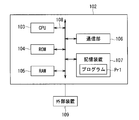
- the information processing apparatus 102 is configured by a general computer in which, for example, a CPU 103, a ROM 104, a RAM 105, a communication unit 106, a storage device 107, and the like are interconnected via a bus line 108.
- the ROM 104 stores basic programs and the like
- the RAM 105 is used as a work area when the CPU 103 performs predetermined processing.
- the communication unit 106 has a data communication function via a communication line such as a LAN.
- the storage device 107 is configured by a nonvolatile storage device such as a flash memory or a hard disk device.
- a program Pr1 is stored in the storage device 107, and various functions of the information processing apparatus 102 are realized by the CPU 103 as a main control unit performing arithmetic processing according to the procedure described in the program Pr1. It is configured.
- the program Pr1 is normally stored and used in advance in a memory such as the storage device 107, but is recorded in a recording medium such as a CD-ROM or DVD-ROM or an external flash memory (program product). (Or provided by downloading from an external server via a network) and may be additionally or exchanged stored in a memory such as the storage device 107.
- some or all of the functions realized in the information processing apparatus 102 may be realized in hardware by a dedicated logic circuit or the like.
- an external device 109 is connected to the information processing side device 102.
- an input device is an input device including at least one of a keyboard, a mouse, various switches, a touch panel, and the like, and is a device that receives various operations (operations such as inputting commands and various data) from an operator.
- the display device is a liquid crystal display device or the like, and is a device that displays various types of information under the control of the CPU 103.
- the external device 109 also includes the crimping side device 101.
- the information processing apparatus 102 includes an information acquisition unit 13, a first storage unit 14, and a transmission unit 15. As described above, each of these functional units is realized, for example, when the CPU 103 performs predetermined arithmetic processing according to the program Pr1.
- the information acquisition unit 13 acquires work information based on the n-th time and the m-th time among a plurality of times of crimping based on the crimping signal output from the output unit 12. For example, the information acquisition unit 13 acquires the time when the n-th crimping signal is output and the time when the m-th crimping signal is output as work information. In this case, in the information acquisition unit 13, the determination of the n-th and m-th crimp signals and the process of measuring the time are performed according to the program Pr1 of the storage device 107.
- the information acquisition unit 13 performs the process from the time when the n-th crimping signal is output to the time when the m-th crimping signal is output, that is, the time when the m-th crimping signal is output and the n-th crimping signal.
- the n-th crimping signal is output by starting the timing from the time when the n-th crimping signal is output and ending the timing at the time when the m-th crimping signal is output. It is also conceivable that the time from when the m-th crimping signal is output is obtained as work information.
- n and m described above are positive integers. Moreover, m is a numerical value larger than n. N is a numerical value of 2 or more.
- the first storage unit 14 stores work information.
- the work information acquired by the information acquisition unit 13 is stored in the first storage unit 14 until the transmission unit 15 transmits the work information to an external device.
- processing is performed in which work information acquired by the information acquisition unit 13 is stored in a free area of the storage device 107.
- the transmission unit 15 is configured to be able to transmit the work information in the first storage unit 14 to an external device (here, the evaluation device 20). For example, the transmission unit 15 performs processing for transmitting work information stored in the storage device 107 to an external device via the communication unit 106.
- the evaluation apparatus 20 calculates the time concerning manufacture of the terminal-attached electric wire 90 based on the work information sent from the terminal-attached electric wire crimping apparatus 10.
- the evaluation device 20 is configured by a general computer in which, for example, a CPU 203, a ROM 204, a RAM 205, a communication unit 206, a storage device 207, and the like are interconnected via a bus line 208.
- the ROM 204 stores basic programs and the like
- the RAM 205 is used as a work area when the CPU 203 performs predetermined processing.
- the communication unit 206 has a data communication function via a communication line such as a LAN.
- the storage device 207 is configured by a nonvolatile storage device such as a flash memory or a hard disk device.
- a program Pr2 is stored in the storage device 207, and the various functions of the evaluation device 20 are realized by the CPU 203 as the main control unit performing arithmetic processing according to the procedure described in the program Pr2.
- the program Pr2 is normally stored and used in advance in a memory such as the storage device 207, but is recorded in a recording medium such as a CD-ROM or DVD-ROM or an external flash memory (program product). (Or provided by downloading from an external server via a network) and may be additionally or exchanged stored in a memory such as the storage device 207.
- some or all of the functions realized in the evaluation device 20 may be realized in hardware by a dedicated logic circuit or the like.
- an input unit 201 and a display unit 202 are connected to the evaluation device 20.
- the input unit 201 is an input device including at least one of a keyboard, a mouse, various switches, a touch panel, and the like, and is considered to be a device that accepts various operations (operations such as inputting commands and various data) from the operator.
- the display unit 202 includes a liquid crystal display device and the like, and is a device that displays various types of information under the control of the CPU 203.
- the evaluation device 20 includes a receiving unit 21, a calculation processing unit 22, a second storage unit 23, and a display unit 24. As described above, each of these functional units is realized, for example, when the CPU 203 performs predetermined arithmetic processing according to the program Pr2.
- the receiving unit 21 is configured to be able to receive work information transmitted from the transmitting unit 15 of the terminal-attached wire crimping device 10.
- processing for receiving work information is performed via the communication unit 206 connected to the communication unit 106 of the information processing side device 102.
- the work information received by the receiving unit 21 is temporarily stored in the storage device 207, for example.
- the work information stored in the storage device 207 is extracted by the calculation processing unit 22 described later, and a unit work time described later is obtained. It is also conceivable that the calculation processing unit 22 to be described later acquires the work information directly via the communication unit 206 and obtains the unit work time.
- the calculation processing unit 22 divides the work time from the n-th crimping to the m-th crimping obtained from the work information received by the receiving unit 21 by the number of machinings obtained by subtracting n from m. Processing for calculating the unit work time of the electric wire 90 is performed. In the calculation processing unit 22, for example, according to the program Pr2 in the storage device 207, processing for obtaining unit work time from work information is performed.
- the second storage unit 23 stores the unit work time obtained by the calculation processing unit 22. In the second storage unit 23, for example, a process of saving the unit work time in an empty area of the storage device 207 is performed.
- the display unit 24 displays the unit work time in the second storage unit 23.
- the display unit 24 displays the unit work time stored in the storage device 207 so that a human can easily determine visually according to a predetermined program.
- the crimp terminal 8 is crimped to the end of the wire 9, and the terminal-attached wire 90 can be obtained.
- a plurality of one type of terminal-attached electric wires 90 are continuously manufactured by a plurality of manufacturing operations.
- the manufacturing operation includes an operation W1 for taking out the electric wire 9 and the crimp terminal 8, and a core wire at the end of the electric wire 9 between the crimping pieces 81 of the crimp terminal 8 before the crimping.
- the first manufacturing operation is an operation performed between the operation W4 and the operation W5 in addition to the operations W1 to W5.
- the tenth manufacturing operation is an operation performed after the operation W5 in addition to the operations W1 to W5, and includes an operation W7 for storing the terminal-attached electric wires 90 in units of ten.
- the evaluation method of the manufacturing work in the manufacturing method of a terminal-attached electric wire according to the present embodiment includes the following first and second steps. First, the first step will be described.
- the first step is a step of acquiring work information based on the time Tn of the nth work timing and the time Tm of the mth work timing among the plurality of manufacturing work.
- a 1st process is performed with the electric wire crimping apparatus 10 with a terminal.
- the work timing is a timing at which the crimp terminal 8 is crimped to the end portion of the electric wire 9 in the manufacturing work. That is, here, the work timing is the timing at which the work W3 is performed. Therefore, in the first step, work information is acquired based on the time Tn during which the work W3 in the nth manufacturing work is performed and the time Tm in which the work W3 in the mth manufacturing work is performed.
- the work information obtained in the first step is time Tn and time Tm. Note that there may be a case where the work information is a difference between the time Tn and the time Tm.
- the second step divides the time from the n-th work timing to the m-th work timing obtained from the work information by the number of machining operations (numerical value) obtained by subtracting n from m.
- This is a step of calculating the unit work time of the per-terminal electric wire 90.
- the second step is performed by the evaluation device 20.
- n and m are positive integers.
- the m is a number larger than n.
- the n is a number of 2 or more. This is because, in the first manufacturing operation, an operation W6 for checking the crimped state between the crimp terminal 8 and the wire 9 of the taken-out terminal-attached electric wire 90 is performed. That is, in the evaluation method of the present embodiment, the operation W3 for one time and the operation W3 for the next time are eliminated by excluding the operation W6 for confirming the crimping state that is not very related to the crimping of the electric wire 9 and the crimp terminal 8. More accurate time (unit working time) is required.
- n 2 and m is 10
- the operation W7 for storing the terminal-attached electric wires 90 in units of ten is performed. That is, in the present embodiment, in the second to tenth manufacturing operations, the unit work time required from one work W3 to the next work W3 is obtained. As shown in FIG. 7, this unit work time corresponds to the time required for one manufacturing work performed continuously after the second time. That is, here, the unit work time corresponds to the time taken for the manufacturing work including the works W1 to W5.
- the unit work time can be obtained by excluding the light work W6 and the work W7 related to the manufacture of the terminal-attached electric wire 90. That is, the time required for the work (work W1 to W5) strongly related to the manufacture of the terminal-attached electric wire 90 can be obtained more accurately.
- steps S1 to S12 performed in the terminal-equipped wire crimping apparatus 10 will be described.
- step S1 As preparation for manufacturing the electric wire 90 with a terminal, for example, the work of confirming whether the product numbers of the crimping terminal 8 and the electric wire 9 constituting the electric wire 90 with a terminal to be manufactured are correct, and to be manufactured from now on.
- movement etc. which move the press part 112 to the position corresponding to the electric wire 90 with a terminal can be considered. These operations are performed by the operator 1 visually confirming or by confirming through a display device connected as the external device 109.
- the manufacturing operation of the electric wire 90 with terminal is started.
- the first manufacturing operation includes the operations W1 to W5, and further includes the operation W6 between the operations W4 and W5.
- the tenth manufacturing operation includes the operations W1 to W5, and further includes the operation W7 after the operation W5.
- the case where it is determined that the manufacturing preparation of the terminal-attached electric wire 90 has been completed is, for example, a case where a predetermined button provided on the terminal-attached electric wire crimping apparatus 10 is pressed after the operator 1 visually confirms. Alternatively, a case where the operator 1 presses a predetermined display on the touch panel provided in the terminal-equipped wire crimping device 10 or a ready-to-read switch display is considered.
- step S2 it is judged whether the crimping
- the information acquisition unit 13 receives the crimp signal sent from the output unit 12, it is determined that there is a crimp signal (YES in step S2). If the information acquisition unit 13 cannot receive the crimp signal, there is no crimp signal. (Step S2 is NO).
- step S3 the number of times of reception of the crimping signal received by the information acquisition unit 13 is expressed by a variable k (step S3).
- the variable k has an initial value of 0, and 1 is added as the information acquisition unit 13 counts the crimping signal once.
- step S4 it is determined whether or not the manufacturing operation is n (here, 2) (step S4).
- n here, 2
- step S4 it is determined whether or not the manufacturing operation is the nth time by comparing n and k and determining whether or not the two match. That is, if n and k in step S3 match, step S4 is YES, and if n and k in step S3 do not match, step S4 is NO.
- step S4 If step S4 is YES, then step S5 for obtaining a time Tn at which the work W3 in the n (here, 2) manufacturing operation is performed is performed. And the time Tn acquired by step S5 is memorize
- step S4 determines whether steps S2 to S4 are made again for the manufacturing operations subsequent to the manufacturing operation of that time. Steps S2 to S4 are performed until k and n match.
- step S4 when step S4 is NO, the acquisition and storage of the time of the work W3 in the manufacturing operation of that time is not performed. Even when step S4 is NO, the time of the work W3 in the manufacturing operation of that time may be acquired and stored.
- step S7 as in step S2, it is determined whether or not a crimping signal has been sent from the output unit 12.
- step S7 If step S7 is YES, the same processing as step S3 is performed (step S8). Then, following step S8, it is determined whether or not the manufacturing operation is m (here, 10th) time (step S9). Here, it is determined whether or not the manufacturing operation is the m-th time by comparing m and k and determining whether or not the two match.
- step S9 If step S9 is YES, then step S10 for obtaining time Tm at which the work W3 in the m (here, 10th) manufacturing operation is performed is performed. Then, the time Tm acquired in step S10 is stored in the first storage unit 14 (step S11).
- step S9 determines whether step S7 to S9 are made for the manufacturing operations subsequent to the manufacturing operation of that time. Steps S7 to S9 are performed until k and m match. In this case as well, when step S9 is NO, the acquisition and storage of the time of the work W3 in the manufacturing operation of that time is not performed. Note that even when step S9 is NO, the time of the work W3 in that manufacturing operation may be acquired and stored.
- step S11 the work information based on the time Tn and the time Tm acquired in steps S1 to S11 is transmitted to an external device (here, the evaluation device 20) (step S12).
- the work information is transmitted in a table formed so that n and m, time Tn and time Tm correspond to each other.
- the work information is sent together in a table of 2 rows and 2 columns.
- Numerical values of n and m are stored in the first row, first column and the first row, second column, respectively.
- numerical values of time Tn and time Tm are stored, respectively.
- Step S12 is executed, and the work information is transmitted to the evaluation device 20, whereby the processing executed in the terminal-attached wire crimping device 10 is completed. Then, the evaluation device 20 performs steps S21 to S24 based on the work information.
- the receiving unit 21 of the evaluation device 20 receives the work information transmitted from the transmitting unit 15 of the terminal-attached wire crimping device 10 (step S21).
- Step S ⁇ b> 22 is performed by the calculation processing unit 22 of the evaluation device 20.
- a unit work time is obtained by dividing a numerical value (work time) obtained by subtracting time Tn from time Tm included in the work information by a numerical value obtained by subtracting n from m (number of machining operations).
- step S22 the work time and the number of machining operations are also obtained, and it is considered that such information is also displayed on the display unit 24 in the result display process described later.
- step S23 a process of storing the result (step S23) is performed.
- the unit work time is stored in the second storage unit 23 (for example, the storage device 207 or the like).
- step S24 a result display process for displaying the unit work time is performed.
- step S ⁇ b> 24 the unit work time stored in the second storage unit 23 is displayed on the display unit 24.
- the unit work time is a symbol corresponding to whether the numerical value is displayed in a graph or whether the unit work time satisfies a predetermined standard. The case where it displays is also considered.
- step S24 it is possible to obtain a unit work time required from the time when the work W3 in the n-th to m-th manufacturing work is performed until the next work W3 is performed. Since this unit work time is the time obtained from the second to the tenth manufacturing operations, the unit operation time per manufacturing operation including only the operations (operations W1 to W5) that are strongly related to the manufacture of the electric wire 90 with terminal is included. It's time. Therefore, by evaluating this unit work time, it is possible to evaluate the work speed and the like of the worker 1.
- N and m are positive integers.
- m is a numerical value larger than n.
- N is a numerical value of 2 or more.
- the unit work time is a time taken from a predetermined work (here, work W3) to a next predetermined work (here, work W3), and is a time taken for one manufacturing work.
- the first manufacturing operation includes operations that are not included in the second and subsequent manufacturing operations, for example, a confirmation operation of the crimping state between the crimp terminal and the electric wire (here, work W6). There are many cases.
- the time required for one manufacturing operation is calculated from the nth and subsequent manufacturing operations excluding the manufacturing operations in which a specific operation is performed among the manufacturing operations performed a plurality of times. For this reason, it is possible to more accurately calculate the time required for one manufacturing operation.
- the predetermined work timing is a timing at which the crimp terminal 8 is crimped to the end portion of the electric wire 9 (a timing at which the work W3 is performed).
- the time when the crimping terminal 8 is crimped to the electric wire 9 by the terminal-equipped wire crimping apparatus 10 can be set as the predetermined work timing, so that the time of the predetermined work timing can be easily measured.
- the electric wire 9 and the crimp terminal 8 are crimped
- the time when the pedal switch 114 is stepped on by the worker 1 can be set as a predetermined work timing. For this reason, the time of the predetermined work timing can be acquired more accurately and easily.
- n is 2.
- the first manufacturing operation often includes an operation for confirming the crimping state between the crimp terminal and the electric wire (here, operation W6). Therefore, in the present embodiment, the unit work time can be calculated more accurately based on the work time in the second and subsequent manufacturing operations.
- the unit work time can be calculated more accurately based on the work time in the manufacturing work from the nth to the 10th time.
- the tenth manufacturing operation may include a light operation related to the crimping of the electric wire 9 and the crimping terminal 8, such as the operation W ⁇ b> 7. For this reason, in this embodiment, the unit work time can be obtained by excluding the work W7.
- the information acquisition unit 13 acquires work information based on the n-th time Tn and the m-th time Tm among a plurality of times of crimping. And the transmission part 15 can transmit work information to an external apparatus (evaluation apparatus 20). In this case, out of the n-th to m-th crimps, the time (unit work time) from the time when one crimping is performed to the next is performed based on the work information. 20 is calculated. For this reason, the electric wire crimping device 10 with a terminal can be made into a simple structure.
- the operation time from the n-th crimping to the m-th crimping obtained from the work information transmitted from the terminal-attached wire crimping apparatus 10 is a value obtained by subtracting n from m. Divide and calculate the unit work time required for crimping one terminal-attached electric wire 90. In this case, the unit work time can be calculated based on the work time from the n-th and subsequent crimps (operation W3) to the m-th crimp (operation W3).
- the transmission part 15 in the electric wire crimping apparatus 10 with a terminal transmits work information
- the receiving part 21 in the evaluation apparatus 20 receives the work information transmitted from the transmission part 15. For this reason, it is also possible to arrange
- the evaluation apparatus 20 performs steps S31 to S37.
- the evaluation device 20 is capable of receiving a plurality of pieces of work information from the terminal-attached wire crimping device 10 and a point that a plurality of unit work times obtained from the plurality of pieces of work information are displayed in a graph. , Different from the above embodiment.
- FIG. 8 is a diagram showing a flow of processing (steps S31 to S37) executed by the evaluation apparatus 20.
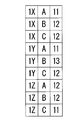
- FIG. 9 is a diagram illustrating an example of a plurality of unit work times stored by the evaluation device 20.
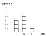
- FIG. 10 is a diagram illustrating an example of a plurality of unit work times graphed. Hereinafter, a different point from said embodiment is demonstrated.
- the terminal-attached wire crimping apparatus 10 acquires a plurality of pieces of work information and transmits the plurality of pieces of work information to the evaluation apparatus 20.
- the work information is information in one production unit required when one worker 1 performs the manufacturing work of one type of terminal-attached electric wire 90 using the terminal-attached electric wire crimping apparatus 10. That is, the work information in one production unit means work information acquired when one worker 1 manufactures one type of terminal-attached electric wire 90.
- the plurality of pieces of work information acquired by the terminal-attached electric wire crimping apparatus 10 means a plurality of types of work information in which at least one of the types of the worker 1 and the terminal-attached electric wire 90 is different.
- the fact that the worker 1 is different means that the person who performs the manufacturing work of the terminal-attached electric wire 90 using the crimping side device 101 is different. More specifically, the case where the person who performs the operation of stepping on the pedal switch 114 of the crimping side apparatus 101 and the operation of setting the electric wire 9 and the crimping terminal 8 are different corresponds to the case where the worker 1 is different.
- the different types of the terminal-attached electric wires 90 mean, for example, a case where the shape of the crimp terminal 8 included in the terminal-attached electric wires 90 is different or a case where the diameters of the electric wires 9 included in the terminal-attached electric wires 90 are different.
- terminal-attached wire crimping apparatus 10 uses the terminal-attached wire crimping apparatus 10, and each of them has three types of terminal-attached wires 90 (hereinafter referred to as A, B, and C types). Will be described.
- step S1 in the process at the side of the terminal-attached wire crimping apparatus 10 as the preparation for manufacturing, the operator indicates that the manufacturer is himself, the predetermined operation and work information corresponding to the work information, and the type of the terminal-attached wire An operation for making these correspond to each other is performed.
- the operator 1X, 1Y, 1Z touches a button, switch, or display on the screen indicating itself, or a predetermined card possessed by the worker 1X, 1Y, 1Z is connected to the terminal-attached wire crimping device 10.
- the information of the workers 1X, 1Y, and 1Z is made to correspond to the work information on the electric wire 90 with a terminal to be manufactured in the future by an operation to be read by the operator.
- an operator touches a button, switch, or display on the screen indicating the type (A to C type) of the terminal-attached electric wire 90 while confirming the display on the screen,
- a button, switch, or display on the screen indicating the type (A to C type) of the terminal-attached electric wire 90 while confirming the display on the screen
- the processing (Pr1) in the terminal-attached wire crimping apparatus 10 as shown in FIG. 3 corresponds to the number of times that the workers 1X to 1Z manufacture the A to C types of terminal-attached wires 90, respectively. By executing (that is, nine times), nine pieces of work information are sequentially transmitted to the evaluation device 20. Note that it is also possible to omit step S12 in the process performed by the first to eighth terminal-attached wire crimping apparatuses 10 and transmit nine pieces of work information to the evaluation apparatus 20 at a time in step S12 of the ninth process. It is done.
- the receiving unit 21 in the evaluation apparatus 20 is configured to be able to receive a plurality of pieces of work information in which at least one of the types of workers 1X to 1Z and the terminal-attached electric wires 90 (A to C types) is different. Also in this example, the receiving unit 21 performs a process of receiving a plurality of pieces of work information transmitted from the terminal-attached wire crimping device 10 via the communication unit 206.
- the calculation processing unit 22 performs a process of calculating a unit work time for each piece of work information. That is, in this example, the calculation processing unit 22 calculates a unit work time for each of nine pieces of work information.
- the display unit 24 graphs and displays a plurality of unit work times calculated for each of a plurality of pieces of work information, with the time as the horizontal axis and the number of production units as the vertical axis.
- the display unit 24 classifies the nine unit work hours for each time, and displays the number of unit work hours for each time as a graph.
- the receiving unit 21 receives a plurality of work information transmitted from the terminal-attached wire crimping apparatus 10 (step S31).
- Each work information includes the work time and the worker 1X.
- Information including 1Y, 1Z and the types (A type to C type) of the electric wire 90 with a terminal.
- Step S32 a plurality of pieces of work information received by the receiving unit 21 are stored in the storage device 207 (step S32).
- Step S32 is performed, for example, when a person performs a predetermined operation using the input unit 201 while confirming on the screen of the display unit 202, or when the reception unit 21 receives the operation, the save operation is automatically performed. The case where it is performed by incorporating the program to be performed is considered.
- Step S33 is a case where one piece of work information is extracted from the storage device 207 by performing a predetermined operation using the input unit 201 while a person confirms on the screen of the display unit 202, or a predetermined program is stored from the storage device 207. The case where an arbitrary thing is taken out according to is considered.
- step S34 a process of calculating a unit work time from the work information extracted in step S33 is performed (step S34).
- Step S ⁇ b> 34 is performed by the calculation processing unit 22.
- stores the calculated unit work time is performed after step S34.
- step S35 as shown in FIG. 9, in each unit work time, the workers 1X to 1Z of the work information used for calculating the unit work time and the types (A to C type) information is stored in an associated state.
- step S36 processing for determining whether other work information is stored in the storage device 207 is performed (step S36). If step S36 is YES, that is, if there is no other work information in the storage device 207, the next step S37 is executed. On the other hand, if step S36 is NO, that is, if other work information remains in the storage device 207, the process of step S33 is performed again. Note that step S36 is performed, for example, by determining whether there is other work information in the storage device 207 by a predetermined program, or when a person uses the storage device 207 via the screen of the display unit 202. It may be possible to check whether there is other work information in the process.
- Step S37 is a process of displaying a plurality of unit work times obtained from each of the plurality of work information as a graph.
- steps S33 to S36 are executed for nine pieces of work information. Then, the recorded nine unit work times are displayed in a graph (step S37), whereby a plurality of unit work times can be easily understood visually.
- FIG. 9 for example, nine unit work times are recorded in a table.
- information including nine unit work hours is summarized in a table of 9 rows and 3 columns.
- the first column is a column indicating the worker.
- information representing one of the workers 1X to 1Z is displayed.
- the second column is a column indicating the type of the electric wire 90 with a terminal to be manufactured.
- information indicating any of the types (A to C types) of the terminal-attached electric wires 90 is displayed.
- unit work times corresponding to the first and second columns of the row are stored. That is, the unit work time obtained from the work information obtained when the worker in the first column of the row performs the work of manufacturing the electric wire with terminal of the second column type in the row is the third column in the row.
- the unit work time calculated from the work information obtained by the worker 1X performing the work of manufacturing the A type terminal-attached electric wire 90 is stored. ing. Note that the unit work time may be in seconds (s) or hours (h).
- step S37 the display unit 24 sorts the nine unit work hours for each hour, and displays the number of unit work hours for each time (ie, the number of production units) as a graph. is doing.
- the display unit 24 displays the number of unit work hours for each time (ie, the number of production units) as a graph. is doing.
- FIG. 10 an example of the graph displayed by the display unit 24 is shown in FIG.
- the unit work time obtained from a plurality of work information is sorted for each time on the horizontal axis, and the number of unit work hours (number of production units) in that time is shown on the vertical axis. It is shown in For this reason, the average value and deviation in a plurality of unit work hours can be easily grasped visually.
- the predetermined work timing may be a timing at which any one of the works W1, W2, W4, and W5 is performed instead of the timing at which the work W3 is performed.
- the evaluation method of the manufacturing operation, the terminal-attached electric wire crimping device, the evaluation device, and the manufacturing operation evaluation system in the method for manufacturing a terminal-attached electric wire according to the present invention are shown above within the scope of the invention described in each claim.
- the embodiment, the modification, and the application example can be freely combined, or the embodiment, the modification, and the application example can be appropriately modified or partly omitted.
Landscapes
- Engineering & Computer Science (AREA)
- Manufacturing & Machinery (AREA)
- Business, Economics & Management (AREA)
- General Physics & Mathematics (AREA)
- Physics & Mathematics (AREA)
- Manufacturing Of Electrical Connectors (AREA)
- Tourism & Hospitality (AREA)
- Economics (AREA)
- Primary Health Care (AREA)
- Strategic Management (AREA)
- Human Resources & Organizations (AREA)
- General Health & Medical Sciences (AREA)
- General Business, Economics & Management (AREA)
- Marketing (AREA)
- Theoretical Computer Science (AREA)
- General Engineering & Computer Science (AREA)
- Quality & Reliability (AREA)
- Automation & Control Theory (AREA)
- Health & Medical Sciences (AREA)
- General Factory Administration (AREA)
Abstract
連続して行われる製造作業のうち、1回あたりの製造作業にかかる時間をより正確に算出することが可能な技術を提供することを目的とする。1回の製造作業によって電線の端部に圧着端子が圧着されて得られる端子付電線を、製造作業を複数回行うことで連続的に複数製造する端子付電線製造方法における製造作業の評価方法は、複数回の製造作業のうちn回目の製造作業における所定の作業タイミングの時間及びm回目の製造作業における所定の作業タイミングの時間に基づく作業情報を取得する第一工程と、作業情報より得られるn回目の製造作業における所定の作業タイミングからm回目の製造作業における所定の作業タイミングまでの作業時間を、mからnを減算した加工回数で除算し、1つあたりの端子付電線の単位作業時間を算出する第二工程と、を備える。そして、n及びmが正の整数であり、mがnよりも大きく、nが、2以上の数値である。
Description
本発明は、端子付電線を製造する製造作業を評価する技術に関する。
自動車等の車両には、電線の端部に端子が圧着された端子付電線が搭載される。端子付電線は、例えば、特許文献1に示されるように、作業者が圧着装置を用いて連続的に製造される。
また、特許文献2には、多数の工業製品を加工する場合において、その加工時間をカウントし、それを加工個数分で割り、一個あたりの加工にかかる時間を算出することが示されている。
ところで、圧着装置を用いて端子付電線を製造する製造作業には、例えば、電線と圧着端子とを圧着装置に用意する作業、圧着前の圧着端子に電線をセットする作業、圧着端子に電線を圧着する圧着作業及び端子付電線を圧着装置から取り出す作業等が含まれる。
ここで、多数の端子付電線を連続的に製造する場合、1つ目の端子付電線を製造する製造作業には、上記作業の他に、例えば、端子と電線との圧着状態の確認作業等が含まれることが多い。このため、全部の端子付電線の製造作業にかかる時間を加工工数で割った場合には、1回目の製造作業に含まれる確認作業等により、1回の製造作業にかかる時間を正確に算出することが困難である。
本発明は、連続して行われる製造作業のうち、1回あたりの製造作業にかかる時間をより正確に算出することが可能な技術を提供することを目的とする。
第1態様に係る端子付電線製造方法における製造作業の評価方法は、1回の製造作業によって電線の端部に圧着端子が圧着されて得られる端子付電線を、前記製造作業を複数回行うことで連続的に複数製造する端子付電線製造方法における製造作業の評価方法であって、前記複数回の製造作業のうちn回目の前記製造作業における所定の作業タイミングの時間及びm回目の前記製造作業における所定の作業タイミングの時間に基づく作業情報を取得する第一工程と、前記作業情報より得られる前記n回目の前記製造作業における所定の作業タイミングから前記m回目の前記製造作業における所定の作業タイミングまでの作業時間を、前記mから前記nを減算した加工回数で除算し、1つあたりの前記端子付電線の単位作業時間を算出する第二工程と、を備え、前記n及び前記mが正の整数であり、前記mが前記nよりも大きく、前記nが、2以上の数値である。
第2態様に係る端子付電線製造方法における製造作業の評価方法は、第1態様に係る端子付電線製造方法における製造作業の評価方法の一態様である。第2態様に係る端子付電線製造方法における製造作業の評価方法においては、前記作業タイミングは、前記電線の端部に前記圧着端子を圧着するタイミングである。
第3態様に係る端子付電線製造方法における製造作業の評価方法は、第1態様又は第2態様に係る端子付電線製造方法における製造作業の評価方法の一態様である。第3態様に係る端子付電線製造方法における製造作業の評価方法においては、前記nが、2である。
第4態様に係る端子付電線製造方法における製造作業の評価方法は、第1態様から第3態様のいずれか1つに係る端子付電線製造方法における製造作業の評価方法の一態様である。第4態様に係る端子付電線製造方法における製造作業の評価方法においては、前記mが、10である。
第5態様に係る端子付電線圧着装置は、電線の端部に圧着端子を圧着することが可能な圧着部と、前記圧着部が圧着を行うタイミングで圧着信号を出力する出力部と、前記出力部から出力される前記圧着信号に基づいて、複数回の圧着のうちn回目の時間及びm回目の時間に基づく作業情報を取得する情報取得部と、前記作業情報を記憶する記憶部と、前記記憶部の前記作業情報を外部の装置へ送信可能な送信部と、を備え、前記n及び前記mが正の整数であり、前記mが前記nよりも大きく、前記nが、2以上の数値である。
第6態様に係る評価装置は、電線の端部に圧着端子を圧着する作業を複数回行うことで連続的に端子付電線を複数製造する端子付電線圧着装置から送信される情報であり、複数回の圧着のうちn回目の時間及びm回目の時間に基づく作業情報を、受信可能な受信部と、前記作業情報より得られる前記n回目の圧着から前記m回目の圧着までの作業時間を前記mから前記nを減算した加工回数で除算し、1つあたりの前記端子付電線の単位作業時間を算出する処理を行う計算処理部と、前記計算処理部により得られる前記単位作業時間を記憶する記憶部と、前記記憶部の前記単位作業時間を表示する表示部と、を備え、前記n及び前記mが正の整数であり、前記mが前記nよりも大きく、前記nが、2以上の数値である。
第7態様に係る評価装置は、第6態様に係る評価装置の一態様である。第7態様に係る評価装置においては、前記作業情報は、一の作業者が前記端子付電線圧着装置を用いて1種類の前記端子付電線の製造作業を行う場合に求められる一の生産単位における情報であり、前記受信部は、前記作業者及び前記端子付電線の種類の少なくとも一方が異なる複数の前記作業情報を受信可能で、前記計算処理部は、前記複数の作業情報ごとに前記単位作業時間を算出する処理を行い、前記表示部が、時間を横軸とし、また、前記生産単位の数を縦軸として、前記複数の作業情報ごとに算出された複数の前記単位作業時間をグラフ化して表示する。
第8態様に係る製造作業評価システムは、端子付電線圧着装置と評価装置とを備え、前記端子付電線圧着装置は、電線の端部に圧着端子を圧着することが可能な圧着部と、前記圧着部が圧着を行うタイミングで圧着信号を出力する出力部と、前記出力部から出力される前記圧着信号に基づいて、複数回の圧着のうちn回目の時間及びm回目の時間に基づく作業情報を取得する情報取得部と、前記作業情報を記憶する第一記憶部と、前記第一記憶部の前記作業情報を外部の装置へ送信可能な送信部と、を備え、前記評価装置は、前記端子付電線圧着装置の前記送信部から送信される前記作業情報を受信可能な受信部と、前記受信部の前記作業情報により得られる前記n回目の圧着から前記m回目の圧着までの作業時間を、前記mから前記nを減算した加工回数で除算し、1つあたりの端子付電線の単位作業時間を算出する処理を行う計算処理部と、前記計算処理部により得られる前記単位作業時間を記憶する第二記憶部と、前記第二記憶部の前記単位作業時間を表示する表示部と、を備え、前記n及び前記mが正の整数であり、前記mが前記nよりも大きく、前記nが、2以上の数値である。
上記の各態様においては、複数回の製造作業のうちn回目の製造作業における所定の作業タイミングからm回目の製造作業における所定の作業タイミングまでの時間を、mからnを減算した加工回数で除算し、1つあたりの端子付電線の単位作業時間が算出される。そして、n及びmは、正の整数である。また、mは、nよりも大きい数値である。また、nは、2以上の数値である。この場合、1回目の製造作業を除いた、n回目以降の製造作業における所定の作業タイミングからm回目の製造作業における所定の作業タイミングまでの作業時間をもとに、単位作業時間が算出される。なお、単位作業時間は、ある回の所定の作業(例えば、圧着作業)から次の回の所定の作業(例えば、圧着作業)にかかる時間であり、1回の製造作業にかかる時間に相当する。ここで、通常、1回目の製造作業には、2回目以降の製造作業には含まれない作業、例えば、圧着端子と電線との圧着状態の確認作業等が含まれることが多い。従って、上記の各態様では、複数回行われる製造作業のうち特定の作業が行われる回の製造作業を除外したn回目以降の製造作業から1回あたりの製造作業にかかる時間が算出される。このため、1回あたりの製造作業にかかる時間をより正確に算出することが可能となる。
また、第2態様において、所定の作業タイミングは、電線の端部に圧着端子を圧着するタイミングである。この場合、例えば、圧着装置によって圧着端子が電線に圧着された時を所定の作業タイミングとできるため、所定の作業タイミングの時間を容易に測定できる。
また、第3態様において、nは、2である。通常、1回目の製造作業には、初期状態の確認作業又は圧着端子と電線との圧着状態の確認作業等が含まれることが多い。従って、第3態様においては、2回目以降の製造作業における作業時間をもとに、単位作業時間をより正確に算出することが可能となる。
また、第4態様において、mが、10である。通常、生産数の指定は、10であることが多い。従って、第4態様においては、n回目から10回目まで製造作業における作業時間をもとに、単位作業時間をより正確に算出することが可能となる。
また、第5態様においては、情報取得部によって複数回の圧着のうちn回目の時間及びm回目の時間に基づく作業情報が取得される。そして、送信部は、作業情報を外部の装置へ送信可能である。この場合、n回目からm回目までの圧着のうち、ある回の圧着から次の回の圧着にかかる時間を、作業情報をもとに、外部の装置が算出する。このため、端子付電線圧着装置を簡素な構成にすることができる。
また、第6態様においては、端子付電線圧着装置から送信される作業情報より得られるn回目の圧着からm回目の圧着までの作業時間を、mからnを減算した値で除算し、1つあたりの端子付電線の単位作業時間を算出する。そして、n及びmは、正の整数である。また、mは、nよりも大きい数値である。また、nは、2以上の数値である。この場合、n回目以降の圧着からm回目の圧着までの作業時間をもとに、単位作業時間を算出できる。
また、第7態様において、表示部は、時間を横軸とし、また、生産単位の数を縦軸として、複数の生産単位ごとの単位作業時間をグラフ化して表示する。この場合、複数の単位作業時間を視覚的に容易に理解することができる。
また、第8態様においては、端子付電線圧着装置から送信される作業情報より得られるn回目の圧着からm回目の圧着までの作業時間を、mからnを減算した値で除算し、1つあたりの端子付電線の単位作業時間を算出する。そして、n及びmは、正の整数である。また、mは、nよりも大きい数値である。また、nは、2以上の数値である。この場合、n回目以降の圧着からm回目の圧着までの作業時間をもとに、単位作業時間を算出できる。
以下、添付の図面を参照しつつ、実施形態について説明する。以下の実施形態は、本発明を具現化した一例であり、本発明の技術的範囲を限定する事例ではない。また、図面においては、理解容易のため、各部の寸法や数が誇張または簡略化して図示されている場合がある。
<実施形態>
まず、図1~7を参照しつつ、本実施形態の端子付電線製造方法における製造作業の評価方法、及び、本実施形態の製造作業評価システム100に含まれる端子付電線圧着装置10及び評価装置20について説明する。図1は、製造作業評価システム100における端子付電線圧着装置10及び評価装置20の機能ブロック図である。また、図1は、製造作業評価システム100全体を概略的に示す概略図である。図2,5は、それぞれ端子付電線圧着装置10及び評価装置20のハードウェア構成を示すブロック図である。図3,6は、それぞれ端子付電線圧着装置10にて実行される処理の流れ及び評価装置20にて実行される処理の流れを示す図である。図4は、端子付電線圧着装置10にて取得される作業情報の一例を示す図である。図7は、端子付電線90を製造する製造作業において行われる処理を概略的に示す説明図である。
まず、図1~7を参照しつつ、本実施形態の端子付電線製造方法における製造作業の評価方法、及び、本実施形態の製造作業評価システム100に含まれる端子付電線圧着装置10及び評価装置20について説明する。図1は、製造作業評価システム100における端子付電線圧着装置10及び評価装置20の機能ブロック図である。また、図1は、製造作業評価システム100全体を概略的に示す概略図である。図2,5は、それぞれ端子付電線圧着装置10及び評価装置20のハードウェア構成を示すブロック図である。図3,6は、それぞれ端子付電線圧着装置10にて実行される処理の流れ及び評価装置20にて実行される処理の流れを示す図である。図4は、端子付電線圧着装置10にて取得される作業情報の一例を示す図である。図7は、端子付電線90を製造する製造作業において行われる処理を概略的に示す説明図である。
はじめに、端子付電線90について説明する。端子付電線90は、例えば、自動車等の車両に搭載される。図1に示されるように、端子付電線90は、電線9及び圧着端子8を備える。
電線9は、芯線及び芯線の周囲を覆う絶縁被覆を備える絶縁電線であることが考えられる。芯線は、例えば、銅又はアルミニウム等の金属を主成分とする線状の導電部材であることが考えられる。絶縁被覆は、例えば、ポリエチレン、塩化ビニル又はポリアミド系ナイロン等を主成分とする合成樹脂の絶縁部材であることが考えられる。なお、図1において、端子付電線90は、簡略化して示されている。
また、端子付電線90において、圧着端子8は、銅等の金属を主成分とする部材である。本実施形態では、電線9の端部の絶縁被覆が除去され、芯線が露出した状態で、この露出した芯線に圧着端子8が圧着されることで、電線9と圧着端子8とが接続される。
また、ここでは、圧着端子8は、電線9の端部の芯線の周囲を覆う状態でかしめられることで、電線9の端部の芯線に接続されるかしめ片81を有する。なお、圧着前の状態では、かしめ片81は、電線9の両側方へ圧着端子8の底板部から起立して形成されている。また、圧着後の状態では、かしめ片81は、電線9を挟んで圧着端子8の底板部に対向する位置まで曲がって形成され、電線9の端部の芯線の周囲を覆っている。
なお、圧着端子8が、さらに、電線9の絶縁被覆の端部の周囲を覆う状態でかしめられる絶縁被覆用のかしめ片を備えることも考えられる。この場合、圧着端子8は、電線9の絶縁被覆の端部にも圧着される。
<端子付電線圧着装置>
端子付電線圧着装置10は、電線9の端部に圧着端子8を圧着する作業を行い、端子付電線90を製造可能な装置である。ここでは、端子付電線圧着装置10を用いて1回の製造作業が行われることによって、電線9の端部に圧着端子8が圧着された端子付電線90を1つ得ることができる。そして、この端子付電線圧着装置10を用いて製造作業を複数回行うことで、端子付電線90は、連続的に複数製造される。
端子付電線圧着装置10は、電線9の端部に圧着端子8を圧着する作業を行い、端子付電線90を製造可能な装置である。ここでは、端子付電線圧着装置10を用いて1回の製造作業が行われることによって、電線9の端部に圧着端子8が圧着された端子付電線90を1つ得ることができる。そして、この端子付電線圧着装置10を用いて製造作業を複数回行うことで、端子付電線90は、連続的に複数製造される。
本実施形態において、端子付電線圧着装置10は、図1に示されるように、圧着側装置101と情報処理側装置102とを備える。ここでは、圧着側装置101は、圧着部11と出力部12とを備える。情報処理側装置102は、情報取得部13と第一記憶部14と送信部15とを備える。
まず、本実施形態の圧着側装置101について説明する。ここでは、圧着側装置101は、圧着部11及び出力部12の他に、ペダルスイッチ114をさらに備えている。
圧着部11は、電線9の端部に圧着端子8を圧着することが可能である。ここでは、図1に示されるように、圧着部11は、圧着端子8を支持することが可能な圧着台111と、圧着端子8のかしめ片81に接触し、電線9の端部にかしめ片81を押し付けながら圧着する押圧部112と、押圧部112を圧着台111に接近及び離隔可能に支持する昇降機構113と、を備える。
本実施形態において、圧着台111には、圧着端子8の底板部を収容可能な溝が形成されていることが考えられる。圧着台111に形成された溝は、収容された圧着端子8の位置決め及びかしめ片81を電線9の周囲を覆うように曲がった形状に案内することが可能な溝である。従って、ここでは、圧着台111に形成された溝に圧着端子8が収容された状態で、電線9との製造作業が行われる。
また、押圧部112は、圧着端子8のかしめ片81に接触する部分であり、かしめ片81を電線9の端部の芯線の周囲を覆う形状に変形させることが可能である。ここでは、押圧部112には、電線9に圧着された後の状態のかしめ片81の外周面に沿う溝が形成されていることが考えられる。押圧部112に形成された溝は、圧着台111に支持された圧着端子8の圧着前のかしめ片81に接触し、電線9の端部の芯線の周囲を覆う形状へ案内するような溝である。
また、エアシリンダ、油圧シリンダ、リニアモータ等のアクチュエータによって構成された昇降機構113は、押圧部112を圧着台111に接近させ、圧着端子8を電線9の端部に圧着すること、及び、圧着が完了した後、押圧部112を圧着台111から離隔させることが可能である。
出力部12は、圧着部11が圧着を行うタイミングで、圧着信号を出力する。ここでは、圧着側装置101のペダルスイッチ114が作業者1に踏まれることで、出力部12が圧着信号を出力する構成とされている。
圧着側装置101のペダルスイッチ114は、作業者1の足元に設けられている。ここでは、ペダルスイッチ114が作業者1に踏まれることで、昇降機構113が作動し、押圧部112が圧着台111に接近させられ、その後、圧着台111から離隔させられる。
また、本実施形態では、ペダルスイッチ114が作業者1に踏まれることで、昇降機構113が作動するとともに、出力部12から圧着信号が出力される。従って、ここでは、ペダルスイッチ114は、昇降機構113を作動させつつ、出力部12から圧着信号を情報処理側装置102に出力するためのスイッチである。
以下、圧着側装置101によって電線9の端部に圧着端子8が圧着される流れについて説明する。本実施形態では、まず、圧着台111に圧着端子8のかしめ片81間に、電線9の端部の露出した芯線が配設された状態で、作業者1の足元に設けられたペダルスイッチ114が踏まれる。これにより、出力部12から圧着信号が圧着部11へ出力され、昇降機構113が作動する。そして、昇降機構113が作動することで、押圧部112が、圧着台111に接近し、圧着端子8のかしめ片81が電線9の端部の芯線の周囲を覆う状態でかしめられ、圧着端子8が電線9に圧着された端子付電線90が製造される。その後、昇降機構113によって押圧部112が圧着台111から離隔し、端子付電線90が取り出される。
次に、本実施形態の情報処理側装置102について説明する。情報処理側装置102は、出力部12から出力される圧着信号に基づき、その圧着が何回目の圧着であるか、を判定する。図2に示されるように、情報処理側装置102は、例えば、CPU103、ROM104、RAM105、通信部106、記憶装置107等が、バスライン108を介して相互接続された一般的なコンピューターによって構成されている。ここでは、ROM104は、基本プログラム等を格納しており、RAM105はCPU103が所定の処理を行う際の作業領域として供される。通信部106は、LAN等の通信回線を介したデータ通信機能を有する。記憶装置107は、フラッシュメモリ、あるいは、ハードディスク装置等の不揮発性の記憶装置によって構成されている。
記憶装置107にはプログラムPr1が格納されており、このプログラムPr1に記述された手順に従って、主制御部としてのCPU103が演算処理を行うことにより、情報処理側装置102の各種機能が実現されるように構成されている。プログラムPr1は、通常、予め記憶装置107等のメモリに格納されて使用されるものであるが、CD-ROMあるいはDVD-ROM、外部のフラッシュメモリ等の記録媒体に記録された形態(プログラムプロダクト)で提供され(あるいは、ネットワークを介した外部サーバからのダウンロードなどにより提供され)、追加的または交換的に記憶装置107等のメモリに格納されるものであってもよい。もっとも、情報処理側装置102において実現される一部あるいは全部の機能は、専用の論理回路等でハードウェア的に実現されてもよい。
また、図2に示されるように、情報処理側装置102には、外部装置109が接続されている。外部装置109としては、入力装置、表示装置等が考えられる。入力装置は、キーボード、マウス、各種スイッチ、タッチパネル等の少なくとも1つを含む入力デバイスであり、オペレータからの各種の操作(コマンドや各種データの入力といった操作)を受け付ける装置である。また、表示装置は、液晶表示装置等により構成されており、CPU103による制御の下、各種の情報を表示する装置である。なお、外部装置109には、圧着側装置101も含まれる。
次に、図1を参照しつつ、情報処理側装置102が備える機能構成について説明する。本実施形態では、情報処理側装置102は、情報取得部13、第一記憶部14及び送信部15を備える。これらの各機能部は、上述した通り、例えば、CPU103がプログラムPr1に従って所定の演算処理を行うことにより実現される。
情報取得部13は、出力部12から出力される圧着信号に基づいて、複数回の圧着のうちn回目の時間及びm回目の時間に基づく作業情報を取得する。例えば、情報取得部13は、n回目の圧着信号が出力された時間及びm回目の圧着信号が出力された時間を作業情報として取得する。この場合、情報取得部13では、記憶装置107のプログラムPr1に従って、n回目及びm回目の圧着信号の判定及びその時間を計測する処理が行われる。
なお、情報取得部13が、n回目の圧着信号が出力された時間からm回目の圧着信号が出力された時間まで、即ち、m回目の圧着信号が出力された時間とn回目の圧着信号が出力された時間との差を、作業情報として取得する場合も考えられる。また、別の態様として、n回目の圧着信号が出力された時間から計時を開始し、m回目の圧着信号が出力された時間で計時を終了することで、n回目の圧着信号が出力された時からm回目の圧着信号が出力された時までの時間を作業情報として取得する場合も考えられる。
また、本実施形態において、上述のn及びmは、正の整数である。また、mは、nよりも大きい数値である。また、nは、2以上の数値である。
次に、第一記憶部14について説明する。第一記憶部14は、作業情報を記憶する。ここでは、情報取得部13によって取得された作業情報が、送信部15によって外部の装置に送信されるまでの間、第一記憶部14に保存される。第一記憶部14では、例えば、情報取得部13によって取得された作業情報が記憶装置107の空き領域に保存される処理が行われる。
送信部15は、第一記憶部14の作業情報を、外部の装置(ここでは、評価装置20)へ送信可能な構成とされている。例えば、送信部15では、記憶装置107に保存された作業情報を、通信部106を介して、外部の装置へと送信される処理が行われる。
なお、端子付電線圧着装置10における具体的な処理の流れについては後述する。
<評価装置>
次に、本実施形態の評価装置20について説明する。ここでは、評価装置20は、端子付電線圧着装置10から送られる作業情報をもとに、端子付電線90の製造に係る時間を算出する。図5に示されるように、評価装置20は、例えば、CPU203、ROM204、RAM205、通信部206、記憶装置207等が、バスライン208を介して相互接続された一般的なコンピューターによって構成されている。ここでは、ROM204は、基本プログラム等を格納しており、RAM205はCPU203が所定の処理を行う際の作業領域として供される。通信部206は、LAN等の通信回線を介したデータ通信機能を有する。記憶装置207は、フラッシュメモリ、あるいは、ハードディスク装置等の不揮発性の記憶装置によって構成されている。
次に、本実施形態の評価装置20について説明する。ここでは、評価装置20は、端子付電線圧着装置10から送られる作業情報をもとに、端子付電線90の製造に係る時間を算出する。図5に示されるように、評価装置20は、例えば、CPU203、ROM204、RAM205、通信部206、記憶装置207等が、バスライン208を介して相互接続された一般的なコンピューターによって構成されている。ここでは、ROM204は、基本プログラム等を格納しており、RAM205はCPU203が所定の処理を行う際の作業領域として供される。通信部206は、LAN等の通信回線を介したデータ通信機能を有する。記憶装置207は、フラッシュメモリ、あるいは、ハードディスク装置等の不揮発性の記憶装置によって構成されている。
記憶装置207にはプログラムPr2が格納されており、このプログラムPr2に記述された手順に従って、主制御部としてのCPU203が演算処理を行うことにより、評価装置20の各種機能が実現されるように構成されている。プログラムPr2は、通常、予め記憶装置207等のメモリに格納されて使用されるものであるが、CD-ROMあるいはDVD-ROM、外部のフラッシュメモリ等の記録媒体に記録された形態(プログラムプロダクト)で提供され(あるいは、ネットワークを介した外部サーバからのダウンロードなどにより提供され)、追加的または交換的に記憶装置207等のメモリに格納されるものであってもよい。もっとも、評価装置20において実現される一部あるいは全部の機能は、専用の論理回路等でハードウェア的に実現されてもよい。
また、図5に示されるように、評価装置20には、入力部201及び表示部202が接続されている。入力部201は、キーボード、マウス、各種スイッチ、タッチパネル等の少なくとも1つを含む入力デバイスであり、オペレータからの各種の操作(コマンドや各種データの入力といった操作)を受け付ける装置であることが考えられる。また、表示部202は、液晶表示装置等により構成されており、CPU203による制御の下、各種の情報を表示する装置である。
次に、図1を参照しつつ、評価装置20が備える機能構成について説明する。本実施形態では、評価装置20は、受信部21、計算処理部22、第二記憶部23及び表示部24を備える。これらの各機能部は、上述した通り、例えば、CPU203がプログラムPr2に従って所定の演算処理を行うことにより実現される。
本実施形態において、受信部21は、端子付電線圧着装置10の送信部15から送信される作業情報を受信可能に構成されている。受信部21では、情報処理側装置102の通信部106に接続された通信部206を介して、作業情報を受信する処理が行われる。
なお、受信部21において受信された作業情報は、例えば、記憶装置207に一時的に保存される。この場合、記憶装置207に保存された作業情報は、後述する計算処理部22において引き出され、後述する単位作業時間が求められる。なお、後述する計算処理部22が、通信部206を介して直接作業情報を取得し、単位作業時間を求める場合も考えられる。
次に、計算処理部22について説明する。計算処理部22は、受信部21で受信した作業情報より得られるn回目の圧着からm回目の圧着までの作業時間を、mからnを減算した加工回数で除算し、1つあたりの端子付電線90の単位作業時間を算出する処理を行う。計算処理部22では、例えば、記憶装置207のプログラムPr2に従って、作業情報より単位作業時間が求められる処理が行われる。
第二記憶部23は、計算処理部22により得られる単位作業時間を記憶する。第二記憶部23では、例えば、単位作業時間が記憶装置207の空き領域に保存される処理が行われる。
表示部24は、第二記憶部23の単位作業時間を表示する。表示部24では、記憶装置207に保存された単位作業時間が、所定のプログラムに従って、人間が視覚的に容易に判断できるように表示される。
<端子付電線製造方法における製造作業の評価方法>
次に、本実施形態の端子付電線製造方法における製造作業の評価方法について説明する。本実施形態において、上記評価方法では、端子付電線圧着装置10及び評価装置20が用いられる。
次に、本実施形態の端子付電線製造方法における製造作業の評価方法について説明する。本実施形態において、上記評価方法では、端子付電線圧着装置10及び評価装置20が用いられる。
即ち、端子付電線圧着装置10を用いて1回の製造作業が行われることで、電線9の端部に圧着端子8が圧着され、端子付電線90を得ることができる。ここでは、複数回の製造作業によって、1種類の端子付電線90が連続的に複数製造される。
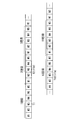
また、本実施形態において、製造作業は、図7に示されるように、電線9及び圧着端子8を取り出す作業W1、圧着前の圧着端子8のかしめ片81間に電線9の端部の芯線をセットする作業W2、圧着端子8を電線9に圧着する作業W3(圧着作業)、圧着部11から圧着端子8が電線9に圧着された端子付電線90を取り出す作業W4、及び、端子付電線90を所定の箇所に置き、保管する作業W5、を備える。
また、図7に示されるように、本実施形態において、1回目の製造作業は、上記作業W1~W5の他に、さらに、作業W4と作業W5との間に行われる作業であり、取り出した端子付電線90の圧着端子8と電線9との圧着状態を調べる作業W6を含む。また、10回目の製造作業は、上記作業W1~W5の他に、さらに、作業W5の後に行われる作業であり、10本単位で端子付電線90を保管する作業W7を含む。
そして、本実施形態の端子付電線製造方法における製造作業の評価方法は、以下に示す第一工程と第二工程とを備える。はじめに第一工程について説明する。
第一工程は、複数回の製造作業のうちn回目の作業タイミングの時間Tn及びm回目の作業タイミングの時間Tmに基づく作業情報を取得する工程である。ここでは、第一工程は、端子付電線圧着装置10にて行われる。
また、本実施形態の第一工程において、上記作業タイミングは、製造作業における電線9の端部に圧着端子8が圧着されるタイミングである。即ち、ここでは、上記作業タイミングは、作業W3が行われるタイミングである。従って、第一工程では、n回目の製造作業における作業W3が行われる時間Tn及びm回目の製造作業における作業W3が行われる時間Tmに基づく作業情報が取得される。
また、本実施形態において、第一工程で得られる作業情報は、時間Tn及び時間Tmである。なお、作業情報が、時間Tnと時間Tmとの差である場合等も考えられる。
また、本実施形態において、第二工程は、作業情報より得られるn回目の作業タイミングからm回目の作業タイミングまでの時間を、mからnを減算した加工回数(数値)で除算し、1つあたりの端子付電線90の単位作業時間を算出する工程である。なお、ここでは、第二工程は、評価装置20にて行われる。
また、端子付電線製造方法における製造作業の評価方法において、上記n及びmは、正の整数である。また、上記mは、nよりも大きい数である。
また、上記nは、2以上の数である。これは、1回目の製造作業においては、取り出した端子付電線90の圧着端子8と電線9との圧着状態を調べる作業W6が行われるためである。即ち、本実施形態の評価方法においては、電線9と圧着端子8との圧着にあまり関係のない圧着状態を確認する作業W6を除くことで、ある回の作業W3と次の回の作業W3との間のより正確な時間(単位作業時間)が求められる。
<処理の流れ>
次に、図1~7を参照しつつ、端子付電線製造方法における製造作業の評価方法にて行われる処理の流れの詳細について説明する。
次に、図1~7を参照しつつ、端子付電線製造方法における製造作業の評価方法にて行われる処理の流れの詳細について説明する。
また、以下では、nが、2であり、さらに、mが、10である事例について説明する。これは、本実施形態では、10回目の製造作業において、10本単位で端子付電線90を保管する作業W7が行われるためである。即ち、本実施形態では、2回目以降10回目までの製造作業において、ある回の作業W3から次の回の作業W3までにかかる単位作業時間が求められる。図7に示されるように、この単位作業時間は、2回目以降連続的に行われる製造作業1回あたりにかかる時間に相当する。即ち、ここでは、単位作業時間は、作業W1~W5を備える製造作業にかかる時間に相当する。この場合、端子付電線90の製造に対して関係のうすい作業W6及び作業W7を除外して、単位作業時間を求めることができる。即ち、端子付電線90の製造に関係の強い作業(作業W1~W5)にかかる時間をより正確に求めることができる。
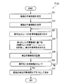
はじめに、端子付電線圧着装置10において行われるステップS1~S12について説明する。本実施形態では、まず、端子付電線圧着装置10において、端子付電線90を製造する準備が完了しているか否かの判断が行われる(ステップS1)。端子付電線90を製造する準備としては、例えば、これから製造する予定の端子付電線90を構成する圧着端子8及び電線9の品番が、正しいか否かの確認作業、及び、これから製造する予定の端子付電線90に対応した位置に押圧部112を移動させる作業等が考えられる。これらの作業は、作業者1が目視で確認することで、若しくは、外部装置109として接続された表示装置を通じて確認することで行われる。
端子付電線90の製造準備が完了したと判断される場合(ステップS1がYESの場合)、端子付電線90の製造作業が開始される。なお、ここでは、上述のように、1回目の製造作業は、上記作業W1~W5にくわえ、さらに、作業W4と作業W5との間に作業W6を含む。また、10回目の製造作業は、上記作業W1~W5にくわえ、さらに、作業W5の後に作業W7を含む。また、端子付電線90の製造準備が完了したと判断される場合とは、例えば、作業者1が目視で確認した後、端子付電線圧着装置10に設けられた所定のボタンが押された場合、或いは、作業者1が端子付電線圧着装置10に設けられたタッチパネルにおける所定の表示、準備完了済みのスイッチ表示が押された場合等が考えられる。
そして、本実施形態では、次に、出力部12から圧着信号が送られてきたか否かの判断が行われる(ステップS2)。ここでは、出力部12から送られる圧着信号を情報取得部13が受信すれば、圧着信号有り(ステップS2がYES)と判断され、情報取得部13が圧着信号を受信できなければ、圧着信号無し(ステップS2がNO)と判断される。
ステップS2がYESの場合、情報取得部13によって受信される圧着信号の受信回数が、変数kによって表現される(ステップS3)。変数kは、初期値が0であり、情報取得部13が圧着信号を1回カウントするにつれ、1が加算される。
ステップS3に続いて、その製造作業が、n(ここでは、2)回目であるか否かが判断される(ステップS4)。ここでは、nとkとを比較し、両者が一致するか否かを判定することで、その製造作業がn回目であるか否かが判断される。即ち、nとステップS3におけるkとが一致する場合、ステップS4がYESとなり、nとステップS3におけるkとが不一致の場合、ステップS4がNOとなる。
ステップS4がYESの場合、続いて、n(ここでは、2)回目の製造作業における作業W3が行われるタイミングの時間Tnを取得するステップS5が行われる。そして、ステップS5によって取得された時間Tnは、第一記憶部14に記憶される(ステップS6)。
一方、ステップS4がNOの場合、その回の製造作業の次の回以降の製造作業に対して、再びステップS2~S4の判断が行われる。ステップS2~S4は、kとnとが一致するまで行われる。なお、本実施形態では、ステップS4がNOである場合、その回の製造作業における作業W3の時間の取得及び記憶が行われない。なお、ステップS4がNOである場合でも、その回の製造作業における作業W3の時間が取得され、記憶される場合も考えられる。
ステップS2~S6によってn回目の作業W3の時間Tnが取得され、記憶された後、続いて、m回目の製造作業における作業W3が行われるタイミングの時間Tmが取得される処理(ステップS7~S11)が行われる。
ステップS7では、ステップS2と同様、出力部12から圧着信号が送られてきたか否かの判断が行われる。
ステップS7がYESの場合、ステップS3と同様の処理が行われる(ステップS8)。そして、ステップS8に続いて、その製造作業が、m(ここでは、10)回目であるか否かが判断される(ステップS9)。ここでは、mとkとを比較し、両者が一致するか否かを判断することで、その製造作業がm回目であるか否かが判定される。
ステップS9がYESの場合、続いて、m(ここでは、10)回目の製造作業における作業W3が行われるタイミングの時間Tmを取得するステップS10が行われる。そして、ステップS10によって取得された時間Tmは、第一記憶部14に記憶される(ステップS11)。
一方、ステップS9がNOの場合、その回の製造作業の次の回以降の製造作業に対して、ステップS7~S9の判断が行われる。ステップS7~S9は、kとmとが一致するまで行われる。なお、ここでも、ステップS9がNOである場合には、その回の製造作業における作業W3の時間の取得及び記憶が行われない。なお、ステップS9がNOである場合でも、その回の製造作業における作業W3の時間が取得され、記憶される場合も考えられる。
ステップS11の後、ステップS1~11によって取得された時間Tn及び時間Tmに基づく作業情報が、外部の装置(ここでは、評価装置20)に送信される(ステップS12)。例えば、作業情報は、図4に示されるように、n及びmと、時間Tn及び時間Tmとが、対応するように作られた表にまとめられて送信される。
より具体的には、ここでは、作業情報は、2行2列の表にまとめられて送信される。1行1列目及び1行2列目には、それぞれn及びmの数値が格納されている。また、2行1列目及び2行2列目には、それぞれ時間Tn及び時間Tmの数値が格納されている。
ステップS12が実行され、評価装置20に作業情報が送信されることで、端子付電線圧着装置10において実行される処理が完了する。そして、評価装置20にて作業情報をもとにステップS21~S24が続いて行われる。
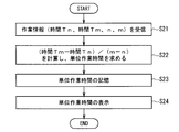
次に、図6を参照しつつ、評価装置20で行われるステップS21~S24について説明する。まず、端子付電線圧着装置10の送信部15から送信される作業情報を、評価装置20の受信部21が受信する(ステップS21)。
続いて、ステップS21にて受信された作業情報から単位作業時間を算出する処理が行われる(ステップS22)。ステップS22は、評価装置20の計算処理部22によって行われる。本実施形態では、作業情報に含まれる時間Tmから時間Tnを減算した数値(作業時間)が、mからnを減算した数値(加工回数)で除算されることで、単位作業時間が求められる。
なお、ステップS22において、作業時間及び加工回数も求められ、後述する結果の表示処理にて、これらの情報も表示部24に表示されることも考えられる。
ステップS22で単位作業時間が算出された後、その結果を記憶する処理(ステップS23)が行われる。ここでは、第二記憶部23(例えば、記憶装置207等)に単位作業時間が保存される。
そして、ステップS23に続いて、単位作業時間を表示する結果の表示処理(ステップS24)が行われる。ステップS24では、第二記憶部23に記憶されていた単位作業時間が、表示部24によって表示される。なお、単位作業時間は、数値として表示部24によって表示される場合の他に、数値をグラフ化して表示される場合又はその単位作業時間が所定の基準を満たしているか否かに対応した記号で表示される場合等も考えられる。
ステップS24が完了することで、n回目からm回目までの製造作業における作業W3が行われてから次の作業W3が行われるまでにかかる単位作業時間を得ることができる。この単位作業時間は、2回目以降10回目までの製造作業より得られた時間であるため、端子付電線90の製造に関係の強い作業(作業W1~W5)のみを含む製造作業1回あたりの時間である。従って、この単位作業時間を評価することで、作業者1の作業速度等を評価することが可能となる。
<効果>
以上のように、本実施形態においては、複数回の製造作業のうちn回目の製造作業における所定の作業タイミング(作業W3のタイミング)からm回目の製造作業における所定の作業タイミング(作業W3のタイミング)までの時間を、nからmを減算した加工回数で除算し、1つあたりの端子付電線90の単位作業時間が算出される。そして、n及びmは、正の整数である。また、mは、nよりも大きい数値である。また、nは、2以上の数値である。この場合、1回目の製造作業を除いた、n(ここでは、2)回目以降の製造作業における所定の作業タイミングからm(ここでは、10)回目の製造作業における所定の作業タイミングまでの作業時間をもとに、単位作業時間が算出される。なお、単位作業時間は、ある回の所定の作業(ここでは、作業W3)から次の回の所定の作業(ここでは、作業W3)にかかる時間であり、1回の製造作業にかかる時間に相当する。ここで、通常、1回目の製造作業には、2回目以降の製造作業には含まれない作業、例えば、圧着端子と電線との圧着状態の確認作業(ここでは、作業W6)等が含まれることが多い。従って、本実施形態では、複数回行われる製造作業のうち特定の作業が行われる回の製造作業を除外したn回目以降の製造作業から1回あたりの製造作業にかかる時間が算出される。このため、1回あたりの製造作業にかかる時間をより正確に算出することが可能となる。
以上のように、本実施形態においては、複数回の製造作業のうちn回目の製造作業における所定の作業タイミング(作業W3のタイミング)からm回目の製造作業における所定の作業タイミング(作業W3のタイミング)までの時間を、nからmを減算した加工回数で除算し、1つあたりの端子付電線90の単位作業時間が算出される。そして、n及びmは、正の整数である。また、mは、nよりも大きい数値である。また、nは、2以上の数値である。この場合、1回目の製造作業を除いた、n(ここでは、2)回目以降の製造作業における所定の作業タイミングからm(ここでは、10)回目の製造作業における所定の作業タイミングまでの作業時間をもとに、単位作業時間が算出される。なお、単位作業時間は、ある回の所定の作業(ここでは、作業W3)から次の回の所定の作業(ここでは、作業W3)にかかる時間であり、1回の製造作業にかかる時間に相当する。ここで、通常、1回目の製造作業には、2回目以降の製造作業には含まれない作業、例えば、圧着端子と電線との圧着状態の確認作業(ここでは、作業W6)等が含まれることが多い。従って、本実施形態では、複数回行われる製造作業のうち特定の作業が行われる回の製造作業を除外したn回目以降の製造作業から1回あたりの製造作業にかかる時間が算出される。このため、1回あたりの製造作業にかかる時間をより正確に算出することが可能となる。
また、本実施形態において、所定の作業タイミングは、電線9の端部に圧着端子8を圧着するタイミング(作業W3が行われるタイミング)である。この場合、例えば、端子付電線圧着装置10によって圧着端子8が電線9に圧着された時を所定の作業タイミングとできるため、所定の作業タイミングの時間を容易に測定できる。
また、本実施形態では、端子付電線圧着装置10にを用いて電線9と圧着端子8との圧着が行われる。そして、ペダルスイッチ114が作業者1によって踏まれた時を、所定の作業タイミングとすることができる。このため、所定の作業タイミングの時間をより正確にかつ簡単に取得することができる。
また、本実施形態において、nは、2である。通常、1回目の製造作業には、圧着端子と電線との圧着状態の確認作業(ここでは、作業W6)等が含まれることが多い。従って、本実施形態では、2回目以降の製造作業における作業時間をもとに、単位作業時間をより正確に算出することが可能となる。
また、本実施形態において、mは、10である。通常、生産数の指定は、10であることが多い。従って、本実施形態では、n回目から10回目まで製造作業における作業時間をもとに、単位作業時間をより正確に算出することが可能となる。また、この場合、10回目の製造作業には、例えば、作業W7のような、電線9と圧着端子8との圧着に関係のうすい作業が含まれることが考えられる。このため、本実施形態では、作業W7を除外して、単位作業時間を求めることができる。
また、本実施形態の端子付電線圧着装置10においては、情報取得部13によって複数回の圧着のうちn回目の時間Tn及びm回目の時間Tmに基づく作業情報が取得される。そして、送信部15は、作業情報を外部の装置(評価装置20)へ送信可能である。この場合、n回目からm回目までの圧着のうち、ある回の圧着が行われた時間から次の回の圧着が行われた時間(単位作業時間)を、作業情報をもとに、評価装置20が算出する。このため、端子付電線圧着装置10を簡素な構成にすることができる。
また、本実施形態の評価装置20においては、端子付電線圧着装置10から送信される作業情報より得られるn回目の圧着からm回目の圧着までの作業時間を、mからnを減算した値で除算し、1つあたりの端子付電線90の圧着にかかる単位作業時間を算出する。この場合、n回目以降の圧着(作業W3)からm回目の圧着(作業W3)までの作業時間をもとに、単位作業時間を算出できる。
また、本実施形態において、端子付電線圧着装置10における送信部15が、作業情報を送信し、評価装置20における受信部21が送信部15から送信された作業情報を受信する。このため、評価装置20と端子付電線圧着装置10とを、離れた位置に配置することも可能である。
<変形例>
次に、図1~5,7~10を参照しつつ、評価装置20にて行われる処理(プログラムPr2)の変形例(プログラムPr2a)について説明する。本例において、評価装置20では、ステップS31~S37が行われる。ここでは、評価装置20は、端子付電線圧着装置10から複数の作業情報を受信可能である点、及び、複数の作業情報から得られる複数の単位作業時間がグラフ化されて表示される点で、上記の実施形態と異なる。
次に、図1~5,7~10を参照しつつ、評価装置20にて行われる処理(プログラムPr2)の変形例(プログラムPr2a)について説明する。本例において、評価装置20では、ステップS31~S37が行われる。ここでは、評価装置20は、端子付電線圧着装置10から複数の作業情報を受信可能である点、及び、複数の作業情報から得られる複数の単位作業時間がグラフ化されて表示される点で、上記の実施形態と異なる。
図8は、評価装置20にて実行される処理の流れ(ステップS31~S37)を示す図である。図9は、評価装置20によって記憶される複数の単位作業時間の一例を示す図である。図10は、グラフ化された複数の単位作業時間の一例を示す図である。以下、上記の実施形態と異なる点について説明する。
本例では、端子付電線圧着装置10が、複数の作業情報を取得し、この複数の作業情報を評価装置20に送信する。ここでは、作業情報は、一の作業者1が、端子付電線圧着装置10を用いて1種類の端子付電線90の製造作業を行う場合に求められる一の生産単位における情報である。即ち、一の生産単位における作業情報とは、一の作業者1が1種類の端子付電線90を製造する場合に取得される作業情報を意味する。
従って、端子付電線圧着装置10にて取得される複数の作業情報とは、作業者1及び端子付電線90の種類の少なくとも一方が異なる複数種類の作業情報を意味する。なお、本例において、作業者1が異なるとは、圧着側装置101を用いて端子付電線90の製造作業を行う者が異なることを意味する。より具体的には、圧着側装置101のペダルスイッチ114を踏む作業及び電線9と圧着端子8とをセットする作業等を行う者が異なる場合が、作業者1が異なる場合に相当する。また、端子付電線90の種類が異なるとは、例えば、端子付電線90に含まれる圧着端子8の形状が異なる場合又は端子付電線90に含まれる電線9の径が異なる場合等を意味する。
ここでは、図9に示されるように、3人の作業者1X,1Y,1Zが端子付電線圧着装置10を用いて、各々が3種類の端子付電線90(以下、A,B,C種の端子付電線と称する)を製造する場合について説明する。
本例では、予め、作業者1X,1Y,1Zに対応した情報及びA~C種の端子付電線に対応した情報が、端子付電線圧着装置10の記憶装置107に保存されている。そして、端子付電線圧着装置10側の処理におけるステップS1では、製造準備として、作業者が、製造者が自身であること示し、作業情報に対応させる所定の操作及び作業情報と端子付電線の種類とを対応させる操作が行われる。例えば、作業者1X,1Y,1Zが、自身を示すボタン、スイッチ、又は画面上の表示をタッチする操作、又は、作業者1X,1Y,1Zが所有する所定のカードを端子付電線圧着装置10に読み込ませる操作等によって、これから製造される端子付電線90における作業情報に作業者1X,1Y,1Zの情報が対応させられる。また、例えば、作業者が、画面の表示を確認しつつ、端子付電線90の種類(A~C種)を示すボタン、スイッチ又は画面上の表示をタッチする操作、又は、端子付電線90の種類(A~C種)の情報をキーボート及びマウス等を用いて作業情報に対応させる所定の操作等を行うことで、これから製造される端子付電線90における作業情報に端子付電線90の種類(A~C種)が対応させられる。
その結果、端子付電線圧着装置10によって、一の生産単位における作業情報が9つ取得され、9つの作業情報を、それぞれ作業者1X~1Z及び端子付電線90の種類(A種~C種)と対応付けて、評価装置20に送信することが可能となる。
また、本例では、例えば、図3に示されるような、端子付電線圧着装置10における処理(Pr1)が、作業者1X~1ZがA~C種の端子付電線90をそれぞれ製造する回数分(即ち、9回)実行されることで、9つの作業情報が順次評価装置20へ送信される。なお、1~8回目の端子付電線圧着装置10にて行われる処理におけるステップS12を省略し、9回目の処理のステップS12にて9つの作業情報を一度に評価装置20に送信する場合も考えられる。
また、本例において、評価装置20における受信部21は、作業者1X~1Z及び端子付電線90の種類(A~C種)の少なくとも一方が異なる複数の作業情報を受信可能に構成されている。本例でも、受信部21では、通信部206を介して、端子付電線圧着装置10から送信される複数の作業情報を受信する処理が行われる。
また、計算処理部22は、複数の作業情報ごとに単位作業時間を算出する処理を行う。即ち、本例では、計算処理部22は、9つの作業情報ごとに単位作業時間をそれぞれ算出する。
また、表示部24は、時間を横軸とし、また、生産単位の数を縦軸として、複数の作業情報ごとに算出された複数の単位作業時間をグラフ化して表示する。ここでは、表示部24は、9つの単位作業時間を、時間ごとに分別し、その時間ごとの単位作業時間の数をグラフ化して表示している。
以下、本例における評価装置20で行われる処理(Pr2a)の詳細について、説明する。
まず、本例では、端子付電線圧着装置10から送信される複数の作業情報を、受信部21が受信する(ステップS31)。各作業情報は、作業時間及びそれに対応付けられた作業者1X.1Y,1Zと端子付電線90の種類(A種~C種)を含む情報である。
そして、ここでは、ステップS31に続いて、受信部21によって受信された複数の作業情報が、記憶装置207に保存される(ステップS32)。ステップS32は、例えば、人が、表示部202の画面で確認しながら入力部201を用いて所定の操作を行うことで行われる場合、又は、受信部21に受信されると自動で保存作業が行われるようにするプログラムを組み込んでおくことで行われる場合等が考えられる。
ステップS32の後、記憶装置207から1つの作業情報が取り出される(ステップS33)。ステップS33は、人が表示部202の画面で確認しながら入力部201を用いて所定の操作を行うことで記憶装置207から1つの作業情報が取り出される場合、又は、記憶装置207から所定のプログラムに従って任意のものが取り出される場合等が考えられる。
その後、ステップS33にて取り出された作業情報から単位作業時間を算出する処理が行われる(ステップS34)。ステップS34は、計算処理部22によって行われる。なお、単位作業時間の求め方は、上記の実施形態と同様であるため、ここでは、その説明を省略する。そして、上記の実施形態と同様、ステップS34の後には、算出された単位作業時間を記憶する処理(ステップS35)が行われる。ここでは、ステップS35において、図9に示されるように、各単位作業時間には、その単位作業時間の算出に用いられた作業情報の作業者1X~1Z及び端子付電線90の種類(A~C種)の情報が対応付けられた状態で記憶される。
そして、本例では、ステップS35に続いて、記憶装置207に、他の作業情報が保存されているか否かを判断する処理が行われる(ステップS36)。ステップS36がYESの場合、即ち、他の作業情報が記憶装置207にない場合、次のステップS37が実行される。一方、ステップS36がNOの場合、即ち、他の作業情報が記憶装置207に残っている場合、再びステップS33の処理が行われる。なお、ステップS36は、例えば、所定のプログラムによって記憶装置207に他の作業情報があるか否かが判断されることで行われる場合、又は、人が表示部202の画面を介して記憶装置207に他の作業情報があるか否かを確認して行われる場合等が考えられる。
ステップS37は、複数の作業情報それぞれから得られる複数の単位作業時間を、グラフ化して表示する処理である。
本例では、9つの作業情報に対して、ステップS33~S36が実行される。そして、記録された9つの単位作業時間がグラフ化して表示される(ステップS37)ことで、複数の単位作業時間を視覚的に容易に理解することができる。
より具体的には、本例では、例えば、図9に示されるように、9つの単位作業時間が表にまとめられて記録されている。ここでは、9つの単位作業時間を含む情報が、9行3列の表にまとめられている。1列目は、作業者を示す欄である。1列目には、作業者1X~1Zのいずれかを表す情報が表示されている。2列目は、製造される端子付電線90の種類を示す欄である。2列目には、端子付電線90の種類(A~C種)のいずれかを表す情報が表示されている。3列目には、その行の1列目及び2列目に対応した単位作業時間が格納されている。即ち、その行の1列目の作業者が、その行の2列目の種類の端子付電線の製造作業を行うことで得られる作業情報から得られる単位作業時間が、その行の3列目に格納されている。
例えば、図9に示される例では、1行3列目には、作業者1XがA種の端子付電線90の製造作業を行うことで得られる作業情報から算出された単位作業時間が格納されている。なお、単位作業時間の単位は、秒(s)である場合又は時(h)である場合等が考えられる。
そして、本例では、ステップS37により、表示部24が、9つの単位作業時間を、時間ごとに分別し、その時間ごとの単位作業時間の数(即ち、生産単位の数)をグラフ化して表示している。ここでは、表示部24により表示されるグラフの一例が、図10に示されている。本例では、図10に示されるように、複数の作業情報より得られる単位作業時間が、横軸の時間ごとに分別され、その時間の単位作業時間の数(生産単位の数)が縦軸で示されている。このため、複数の単位作業時間における平均値及び偏差を視覚的に容易に把握することができる。
<応用例>
上記の実施形態において、所定の作業タイミングが、作業W3が行われるタイミングのかわりに、作業W1,W2,W4,W5のいずれか1つが行われるタイミングであってもよい。また、nからmを減算した数の絶対値を加工回数として求めてもよい。
上記の実施形態において、所定の作業タイミングが、作業W3が行われるタイミングのかわりに、作業W1,W2,W4,W5のいずれか1つが行われるタイミングであってもよい。また、nからmを減算した数の絶対値を加工回数として求めてもよい。
なお、本発明に係る端子付電線製造方法における製造作業の評価方法、端子付電線圧着装置、評価装置及び製造作業評価システムは、各請求項に記載された発明の範囲において、以上に示された実施形態、変形例及び応用例を自由に組み合わせること、或いは、実施形態、変形例及び応用例を適宜、変形する又は一部を省略することによって構成されることも可能である。
1 作業者
10 端子付電線圧着装置
100 製造作業評価システム
101 圧着側装置
102 情報処理側装置
11 圧着部
12 出力部
13 情報取得部
14 第一記憶部
15 送信部
20 評価装置
21 受信部
22 計算処理部
23 第二記憶部
24 表示部
8 圧着端子
9 電線
90 端子付電線
10 端子付電線圧着装置
100 製造作業評価システム
101 圧着側装置
102 情報処理側装置
11 圧着部
12 出力部
13 情報取得部
14 第一記憶部
15 送信部
20 評価装置
21 受信部
22 計算処理部
23 第二記憶部
24 表示部
8 圧着端子
9 電線
90 端子付電線
Claims (8)
- 1回の製造作業によって電線の端部に圧着端子が圧着されて得られる端子付電線を、前記製造作業を複数回行うことで連続的に複数製造する端子付電線製造方法における製造作業の評価方法であって、
前記複数回の製造作業のうちn回目の前記製造作業における所定の作業タイミングの時間及びm回目の前記製造作業における所定の作業タイミングの時間に基づく作業情報を取得する第一工程と、
前記作業情報より得られる前記n回目の前記製造作業における所定の作業タイミングから前記m回目の前記製造作業における所定の作業タイミングまでの作業時間を、前記mから前記nを減算した加工回数で除算し、1つあたりの前記端子付電線の単位作業時間を算出する第二工程と、を備え、
前記n及び前記mが正の整数であり、
前記mが前記nよりも大きく、
前記nが、2以上の数値である、端子付電線製造方法における製造作業の評価方法。 - 請求項1に記載の端子付電線製造方法における製造作業の評価方法であって、
前記作業タイミングは、前記電線の端部に前記圧着端子を圧着するタイミングである、端子付電線製造方法における製造作業の評価方法。 - 請求項1又は請求項2に記載の端子付電線製造方法における製造作業の評価方法であって、
前記nが、2である、端子付電線製造方法における製造作業の評価方法。 - 請求項1から請求項3のいずれか1項に記載の端子付電線製造方法における製造作業の評価方法であって、
前記mが、10である、端子付電線製造方法における製造作業の評価方法。 - 電線の端部に圧着端子を圧着することが可能な圧着部と、
前記圧着部が圧着を行うタイミングで圧着信号を出力する出力部と、
前記出力部から出力される前記圧着信号に基づいて、複数回の圧着のうちn回目の時間及びm回目の時間に基づく作業情報を取得する情報取得部と、
前記作業情報を記憶する記憶部と、
前記記憶部の前記作業情報を外部の装置へ送信可能な送信部と、を備え、
前記n及び前記mが正の整数であり、
前記mが前記nよりも大きく、
前記nが、2以上の数値である、端子付電線圧着装置。 - 電線の端部に圧着端子を圧着する作業を複数回行うことで連続的に端子付電線を複数製造する端子付電線圧着装置から送信される情報であり、複数回の圧着のうちn回目の時間及びm回目の時間に基づく作業情報を、受信可能な受信部と、
前記作業情報より得られる前記n回目の圧着から前記m回目の圧着までの作業時間を前記mから前記nを減算した加工回数で除算し、1つあたりの前記端子付電線の単位作業時間を算出する処理を行う計算処理部と、
前記計算処理部により得られる前記単位作業時間を記憶する記憶部と、
前記記憶部の前記単位作業時間を表示する表示部と、を備え、
前記n及び前記mが正の整数であり、
前記mが前記nよりも大きく、
前記nが、2以上の数値である、評価装置。 - 請求項6に記載の評価装置であって、
前記作業情報は、一の作業者が前記端子付電線圧着装置を用いて1種類の前記端子付電線の製造作業を行う場合に求められる一の生産単位における情報であり、
前記受信部は、前記作業者及び前記端子付電線の種類の少なくとも一方が異なる複数の前記作業情報を受信可能で、
前記計算処理部は、前記複数の作業情報ごとに前記単位作業時間を算出する処理を行い、
前記表示部が、時間を横軸とし、また、前記生産単位の数を縦軸として、前記複数の作業情報ごとに算出された複数の前記単位作業時間をグラフ化して表示する、評価装置。 - 端子付電線圧着装置と評価装置とを備え、
前記端子付電線圧着装置は、
電線の端部に圧着端子を圧着することが可能な圧着部と、
前記圧着部が圧着を行うタイミングで圧着信号を出力する出力部と、
前記出力部から出力される前記圧着信号に基づいて、複数回の圧着のうちn回目の時間及びm回目の時間に基づく作業情報を取得する情報取得部と、
前記作業情報を記憶する第一記憶部と、
前記第一記憶部の前記作業情報を外部の装置へ送信可能な送信部と、を備え、
前記評価装置は、
前記端子付電線圧着装置の前記送信部から送信される前記作業情報を受信可能な受信部と、
前記受信部の前記作業情報により得られる前記n回目の圧着から前記m回目の圧着までの作業時間を、前記mから前記nを減算した加工回数で除算し、1つあたりの端子付電線の単位作業時間を算出する処理を行う計算処理部と、
前記計算処理部により得られる前記単位作業時間を記憶する第二記憶部と、
前記第二記憶部の前記単位作業時間を表示する表示部と、を備え、
前記n及び前記mが正の整数であり、
前記mが前記nよりも大きく、
前記nが、2以上の数値である、製造作業評価システム。
Applications Claiming Priority (2)
| Application Number | Priority Date | Filing Date | Title |
|---|---|---|---|
| JP2015-097202 | 2015-05-12 | ||
| JP2015097202A JP2016213110A (ja) | 2015-05-12 | 2015-05-12 | 端子付電線製造方法における製造作業の評価方法、端子付電線圧着装置、評価装置及び製造作業評価システム |
Publications (1)
| Publication Number | Publication Date |
|---|---|
| WO2016181790A1 true WO2016181790A1 (ja) | 2016-11-17 |
Family
ID=57248797
Family Applications (1)
| Application Number | Title | Priority Date | Filing Date |
|---|---|---|---|
| PCT/JP2016/062735 Ceased WO2016181790A1 (ja) | 2015-05-12 | 2016-04-22 | 端子付電線製造方法における製造作業の評価方法、端子付電線圧着装置、評価装置及び製造作業評価システム |
Country Status (3)
| Country | Link |
|---|---|
| JP (1) | JP2016213110A (ja) |
| TW (1) | TWI602041B (ja) |
| WO (1) | WO2016181790A1 (ja) |
Citations (2)
| Publication number | Priority date | Publication date | Assignee | Title |
|---|---|---|---|---|
| JP2013211000A (ja) * | 2012-02-28 | 2013-10-10 | Sharp Corp | 携帯型端末装置 |
| JP2013218585A (ja) * | 2012-04-10 | 2013-10-24 | Akebono Kikai Kogyo Kk | 作業の指標表示装置とその装置を用いた作業の指標表示方法 |
Family Cites Families (5)
| Publication number | Priority date | Publication date | Assignee | Title |
|---|---|---|---|---|
| WO2008087938A1 (ja) * | 2007-01-16 | 2008-07-24 | Japan Automatic Machine Co., Ltd. | 端子圧着方法、端子圧着装置及び端子圧着電線製造装置 |
| WO2011158390A1 (ja) * | 2010-06-16 | 2011-12-22 | 日本オートマチックマシン株式会社 | 二線式圧着電線製造装置、二線式圧着電線製造方法、二線式電線送給装置 |
| WO2012018049A1 (ja) * | 2010-08-06 | 2012-02-09 | 株式会社オートネットワーク技術研究所 | 端子付き電線、及びコネクタ |
| JP2013246886A (ja) * | 2012-05-23 | 2013-12-09 | Auto Network Gijutsu Kenkyusho:Kk | 端子付き電線およびその製造方法、ならびに治具 |
| JP6100138B2 (ja) * | 2013-10-17 | 2017-03-22 | 日本オートマチックマシン株式会社 | 端子送り装置、端子圧着機用アプリケータ、端子圧着機及び端子圧着電線の製造方法 |
-
2015
- 2015-05-12 JP JP2015097202A patent/JP2016213110A/ja not_active Withdrawn
-
2016
- 2016-04-22 WO PCT/JP2016/062735 patent/WO2016181790A1/ja not_active Ceased
- 2016-04-26 TW TW105112962A patent/TWI602041B/zh not_active IP Right Cessation
Patent Citations (2)
| Publication number | Priority date | Publication date | Assignee | Title |
|---|---|---|---|---|
| JP2013211000A (ja) * | 2012-02-28 | 2013-10-10 | Sharp Corp | 携帯型端末装置 |
| JP2013218585A (ja) * | 2012-04-10 | 2013-10-24 | Akebono Kikai Kogyo Kk | 作業の指標表示装置とその装置を用いた作業の指標表示方法 |
Also Published As
| Publication number | Publication date |
|---|---|
| JP2016213110A (ja) | 2016-12-15 |
| TWI602041B (zh) | 2017-10-11 |
| TW201706742A (zh) | 2017-02-16 |
Similar Documents
| Publication | Publication Date | Title |
|---|---|---|
| JP3154740B2 (ja) | 圧着接続端子の圧着品質決定方法 | |
| JP6209959B2 (ja) | 表示方法、表示装置及び表示プログラム | |
| CN108184109A (zh) | 一种车载信息娱乐系统的测试平台及测试方法 | |
| US9632656B2 (en) | Methods and systems for displaying vehicle data parameters with a uniform cursor movement | |
| CN106506251B (zh) | 信息处理装置、不良现象原因确定方法 | |
| EP3338411B1 (en) | In-vehicle infotainment system interoperability testing device | |
| EP1870720B1 (en) | Terminal crimped state testing method | |
| JP2020064429A (ja) | 作業情報管理システム及びウェアラブルセンサ | |
| JP5883735B2 (ja) | 圧着端子のクリンプハイト測定方法及びその装置、クリンプハイト管理方法及びその装置 | |
| JP4070705B2 (ja) | 端子圧着不良検出装置 | |
| WO2016181790A1 (ja) | 端子付電線製造方法における製造作業の評価方法、端子付電線圧着装置、評価装置及び製造作業評価システム | |
| CN116841868A (zh) | 针对触摸屏tp算法的调试方法和相关tp算法调试系统 | |
| CN105808406B (zh) | 一种监控方法和电子设备 | |
| WO2025022612A1 (ja) | 評価システムおよび評価方法 | |
| JP2014127430A (ja) | 端子圧着装置の圧力センサ取付構造とそれを用いた圧着力検査方法 | |
| CN119045454A (zh) | 一种电子产品中硬件控制器的测试装置及其使用方法 | |
| CN111141941A (zh) | 一种双通道示波器及其控制方法和存储介质 | |
| JP2010040481A (ja) | 端子圧着状態良否判別装置、端子圧着加工装置、端子圧着状態良否判別方法及び端子圧着状態良否判別プログラム | |
| JP2010049529A (ja) | 作業情報処理装置、プログラムおよび作業情報処理方法 | |
| JP2005135820A (ja) | 端子圧着不良検出装置 | |
| KR101723040B1 (ko) | 단자 압착기 및 이를 이용한 단자 압착방법 | |
| JP4815457B2 (ja) | ワイヤーハーネス結線作業の自動検討システム | |
| CN212110329U (zh) | 汽车内外饰外观件色差检测系统 | |
| KR101940121B1 (ko) | 와이어링 시스템 중량 산출 장치 | |
| WO2011126813A1 (en) | Method to determine a quality acceptance criterion using force signatures |
Legal Events
| Date | Code | Title | Description |
|---|---|---|---|
| 121 | Ep: the epo has been informed by wipo that ep was designated in this application |
Ref document number: 16792515 Country of ref document: EP Kind code of ref document: A1 |
|
| NENP | Non-entry into the national phase |
Ref country code: DE |
|
| 122 | Ep: pct application non-entry in european phase |
Ref document number: 16792515 Country of ref document: EP Kind code of ref document: A1 |