WO2016181519A1 - 矢印信号機検出装置及び矢印信号機検出方法 - Google Patents
矢印信号機検出装置及び矢印信号機検出方法 Download PDFInfo
- Publication number
- WO2016181519A1 WO2016181519A1 PCT/JP2015/063729 JP2015063729W WO2016181519A1 WO 2016181519 A1 WO2016181519 A1 WO 2016181519A1 JP 2015063729 W JP2015063729 W JP 2015063729W WO 2016181519 A1 WO2016181519 A1 WO 2016181519A1
- Authority
- WO
- WIPO (PCT)
- Prior art keywords
- arrow
- signal
- pattern
- traffic
- traffic light
- Prior art date
- Legal status (The legal status is an assumption and is not a legal conclusion. Google has not performed a legal analysis and makes no representation as to the accuracy of the status listed.)
- Ceased
Links
Images









Classifications
-
- G—PHYSICS
- G06—COMPUTING OR CALCULATING; COUNTING
- G06T—IMAGE DATA PROCESSING OR GENERATION, IN GENERAL
- G06T7/00—Image analysis
-
- G—PHYSICS
- G08—SIGNALLING
- G08G—TRAFFIC CONTROL SYSTEMS
- G08G1/00—Traffic control systems for road vehicles
-
- G—PHYSICS
- G08—SIGNALLING
- G08G—TRAFFIC CONTROL SYSTEMS
- G08G1/00—Traffic control systems for road vehicles
- G08G1/09—Arrangements for giving variable traffic instructions
-
- G—PHYSICS
- G08—SIGNALLING
- G08G—TRAFFIC CONTROL SYSTEMS
- G08G1/00—Traffic control systems for road vehicles
- G08G1/16—Anti-collision systems
Definitions
- the present invention relates to an arrow traffic light detection device and an arrow traffic light detection method.
- Patent Document 1 the distance from the own vehicle to the traffic signal is classified into three stages (short distance, medium distance, long distance), and an arrow signal is detected using a different method at each stage.
- the present invention has been made in view of the above problems, and an object of the present invention is to detect an arrow traffic light detection device and an arrow traffic light detection method capable of reducing the system load by detecting the direction of an arrow signal using a single method. Is to provide.
- the arrow traffic light detection apparatus images the surroundings of the host vehicle using the imaging unit, and generates arrow rotation patterns in a plurality of different directions obtained by rotating the arrow shape pattern at a predetermined angle. Subsequently, the arrow traffic light detector detects the arrow signal by performing pattern matching on the captured image while changing the position on the image and the arrow rotation pattern.
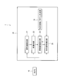
- FIG. 1 is a configuration diagram of an arrow traffic light detection apparatus according to the first embodiment of the present invention.
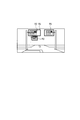
- FIG. 2A and FIG. 2B are diagrams for explaining a signal detection method.
- FIG. 3 is a diagram for explaining another detection method of a traffic light.
- FIG. 4 is a diagram for explaining a method for detecting a traffic light.
- FIG. 5 is a diagram for explaining a method of generating an arrow rotation pattern.
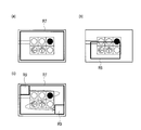
- 6A, 6B, and 6C are diagrams for explaining a method of detecting an arrow signal.
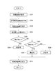
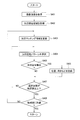
- FIG. 7 is a flowchart for explaining a signal detection method.
- FIG. 8 is a flowchart for explaining a method of identifying a traffic light.
- FIG. 9 is a flowchart for explaining an area for searching for an arrow signal.
- FIG. 1 is a configuration diagram of an arrow traffic light detection apparatus according to the first embodiment of the present invention.
- FIG. 2A and FIG. 2B are diagrams for explaining a signal detection
- FIG. 10 is a flowchart illustrating a method for detecting an arrow signal.
- FIG. 11 is a diagram for explaining the weighting of the arrow rotation pattern.
- FIG. 12 is a configuration diagram of an arrow traffic light detection apparatus according to the second embodiment of the present invention.
- FIG. 13 is a diagram for explaining a signal detection method.
- FIG. 14 is a diagram for explaining an arrow signal detection method.
- FIG. 15 is a diagram for explaining a method of generating an arrow rotation pattern.
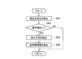
- FIG. 16 is a flowchart for explaining a method for detecting intersection and traffic signal information.
- FIG. 17 is a flowchart for explaining a signal detection method.
- FIG. 18 is a flowchart for explaining an area for searching for an arrow signal.
- FIG. 19 is a diagram for explaining the weighting of the arrow rotation pattern.
- FIG. 20 is a diagram for explaining an area for searching for a traffic light.
- the structure of the arrow traffic light detection apparatus 1 which concerns on 1st Embodiment of this invention is demonstrated.
- the arrow traffic light detection device 1 includes a camera 10 and a traffic light detection device 20.
- the camera 10 (imaging unit) includes a camera having an image sensor such as a CCD or a CMOS, and an image processing unit.
- the camera 10 is installed in the own vehicle, and images the surroundings of the own vehicle continuously in time.
- the image processing unit performs predetermined image processing on the captured image (hereinafter simply referred to as a captured image), and outputs the processed image to the traffic light detection device 20.
- the traffic light detection device 20 is a computer including, for example, a CPU, a ROM, a RAM, a data bus connecting them, and an input / output interface, and the CPU performs a predetermined process according to a program stored in the ROM.
- the traffic signal detection device 20 classifies the traffic signal detection unit 21 into a traffic signal detection unit 21, a color identification unit 22, a search region setting unit 23, an arrow rotation pattern generation unit 24, and an arrow signal detection unit 25. be able to.
- the traffic light detection unit 21 detects the position and size of the traffic light from the captured image, and outputs the detection result to the color identification unit 22. Specifically, as shown in FIG. 2A, the traffic light detection unit 21 has a rectangular normal search area R1 for searching for traffic lights in an area where there is a traffic signal in an area higher than the road surface above the captured image. Set. In addition, the traffic signal detection part 21 can also estimate the area
- the traffic signal detection unit 21 applies the traffic signal model learned in advance to the matching region R2. Then, the traffic light detection unit 21 performs pattern matching while moving the coordinates of the matching region R2 to the left and right from the upper left to the lower right of the normal search region R1, as indicated by the dotted arrows in FIG. Is detected. Note that the traffic light detection unit 21 can perform pattern matching while changing the size of the matching region R2. Then, the traffic signal detection unit 21 outputs the detected position and size of the traffic signal to the color identification unit 22.
- the traffic light detection unit 21 can set the priority search region R3 in the captured image.
- the priority search area R3 is an area set for the captured image captured this time using information on the position and size of the traffic light detected on the previous captured image.
- the priority search area R3 is based on the movement (speed, direction) of the host vehicle from the previous time to the current imaging based on the information on the position and size of the traffic light detected on the previous captured image. This can be obtained by predicting the position and size of the traffic light on the captured image. How it changes depending on the speed of the host vehicle can be obtained in advance through experiments and simulations.
- the priority search area R3 is set using the information on the position and size of the traffic light detected on the captured image, and thus is smaller than the normal search area R1. Thereby, the range in which the matching area R2 is moved is smaller than the normal search area R1. Therefore, the traffic signal detection unit 21 can reduce the system load related to the detection of the traffic signal by setting the priority search region R3.
- the color identification unit 22 identifies the color of the traffic light from the captured image and the output of the traffic signal detection unit 21, and outputs the identification result to the search area setting unit 23. Specifically, as shown in FIGS. 4 (a) to 4 (c), the color identification unit 22 performs three color identification regions R4 to R6 for the traffic lights detected by the traffic light detection unit 21. Set. More specifically, the color identifying unit 22 sets color identifying regions R4 to R6 having a length of r ⁇ w / 3 at the left and right and the center of the traffic light, where w is the lateral length of the traffic light. r is a coefficient that changes according to the size of the traffic light.
- the color identification unit 22 assigns the pixel values of the set color identification regions R4 to R6 to the HSV color space.
- red, yellow, and green regions are preset.
- the color identification unit 22 identifies an area having the largest number of pixel values among the pixel values assigned to each of the red, yellow, and green areas as a lighting color. Then, the color identification unit 22 outputs the light color of the identified traffic light to the search area setting unit 23.
- the arrow rotation pattern generation unit 24 rotates the arrow-shaped arrow reference pattern P1 generated in advance by 45 degrees to generate a seven-direction arrow rotation pattern P2.
- the arrow rotation pattern generation unit 24 includes a reference pattern generation unit that the arrow reference pattern P1 generates. The generation method will be described. First, the arrow rotation pattern generation unit 24 includes a plurality of arrow rotation pattern generation units 24 stored in the traffic light detection device 20. An arrow signal image is acquired, and the direction of the arrow signal of the acquired image is aligned in the upward direction (straight direction).
- the reference pattern generation unit performs machine learning using images with the same orientation, and generates one type of arrow reference pattern P1 specialized for detecting an arrow signal. Then, the arrow rotation pattern generation unit 24 generates an arrow rotation pattern P2 using the arrow reference pattern P1 generated in this way, and outputs the arrow rotation pattern P2 to the arrow signal detection unit 25.
- the search area setting unit 23 sets an area for searching for an arrow signal attached to the traffic light from the output of the color identification unit 22, and outputs the setting result to the arrow signal detection unit 25.
- the search area setting unit 23 is a rectangular arrow search area R7 (in the second search area) that is a predetermined distance or a predetermined pixel away from the position of the traffic light on the captured image. Equivalent).
- the predetermined distance or the predetermined pixel can be set as a size corresponding to one light of a traffic light.
- the traffic light detection unit 21 performs pattern matching from the normal search region R1, and the coordinates of the traffic light detected can be used.
- the search area setting unit 23 uses the information on the position and magnitude of the arrow signal acquired from the arrow signal detection unit 25 described later, as shown in FIG. 6B, the existing arrow area R8 (first search). Corresponding to the area) can be set.
- the existing arrow region R8 is a region set for the captured image captured this time using information on the position and magnitude of the arrow signal detected on the previous captured image. Similar to the priority search region R3 described above, the existing arrow region R8 is based on information on the position and size of the arrow signal detected on the previous captured image, and the movement (speed, The direction and the size of the traffic light on the captured image can be predicted based on the (direction). For example, the size of the existing arrow region R8 can be set as the size of one traffic light around the detected arrow signal light.
- the arrow signal detection unit 25 applies the arrow rotation pattern P2 to the arrow matching region R9 for the arrow search region R7 set by the search region setting unit 23. . Then, the arrow signal detection unit 25 changes the coordinates of the arrow matching region R9 from the start position at the upper left of the arrow search region R7 to the lower right and left as shown by the dotted arrow in FIG. However, pattern matching is performed while the arrow rotation pattern P2 is changed to a different rotation angle, and an arrow signal is detected.
- the arrow signal detection unit 25 moves the coordinates of the arrow matching region R9 by changing the position on the image in the horizontal direction by, for example, one pixel, and then changes the arrow rotation pattern P2 by different rotation angles one by one. Then, pattern matching is performed, and pattern matching of all the arrow rotation patterns P2 is performed, and then the next coordinate is moved.
- the arrow signal detection unit 25 changes and moves the coordinates of the arrow matching region R9, the arrow signal detection unit 25 temporarily performs pattern matching to the lower right end of the arrow search region R7 using one arrow rotation pattern P2.
- Another arrow rotation pattern P2 having a different rotation angle may be selected and moved again while changing the coordinates of the arrow matching region R9 from the upper left start position of the arrow search region R7 toward the lower right and left.
- the arrow signal detection unit 25 can perform pattern matching while changing the size of the arrow matching region R9. Then, the arrow signal detection unit 25 outputs arrow signal information such as the position, orientation, and magnitude of the detected arrow signal to the search region setting unit 23.
- the arrow signal detection unit 25 performs pattern matching on the existing arrow region R8. Since the existing arrow area R8 is smaller than the arrow search area R7, the range in which the arrow matching area R9 is moved is smaller than the arrow search area R7. Therefore, the arrow signal detection unit 25 can reduce the system load related to the detection of the arrow signal by using the existing arrow region R8. Further, when the existing arrow region R8 is used, since the direction of the arrow signal is detected in the previous captured image, the arrow signal detection unit 25 selects the arrow rotation pattern P2 that matches the detected direction of the arrow signal. Pattern matching can be performed. Thus, when using the existing arrow area
- step S ⁇ b> 101 the traffic light detection unit 21 acquires a captured image from the camera 10.
- step S102 the traffic light detection unit 21 determines whether or not the priority search region R3 has been created. If the priority search region R3 has not been created (No in step S102), the process proceeds to step S103. On the other hand, when the priority search region R3 has been created (Yes in step S102), the process proceeds to step S104.
- step S103 the traffic light detection unit 21 sets the normal search region R1 in the captured image.
- step S104 the traffic light detection unit 21 sets the created priority search region R3.
- step S105 the traffic signal detection unit 21 performs pattern matching using the traffic signal model in the normal search region R1 or the priority search region R3. If a traffic light is detected by pattern matching (Yes in step S105), the process proceeds to step S106. On the other hand, when no traffic light is detected (No in step S105), a series of processing ends.
- step S106 the traffic light detection unit 21 creates a priority search region R3 to be set for the next captured image based on the detected position and size of the traffic light, the vehicle speed, and the like.
- step S107 the traffic signal detection unit 21 outputs the traffic signal detection result to the color identification unit 22, and the series of processing ends.
- step S201 the color identification unit 22 acquires a captured image from the camera 10.
- step S202 the color identifying unit 22 acquires the position and size of the traffic light from the traffic light detection unit 21.
- step S203 the color identification unit 22 sets the color identification regions R4 to R6 in the acquired traffic signal.
- step S204 the color identification unit 22 assigns the pixel values of the set color identification regions R4 to R6 to the HSV color space.
- step S205 the color identification unit 22 determines whether or not the region having the largest number of pixel values among the pixel values assigned to the red, yellow, and green regions is green.
- the process proceeds to step S206.
- the process proceeds to step S207.
- step S207 the color identification unit 22 determines whether or not the region having the largest number of pixel values among the pixel values assigned to the red, yellow, and green regions is yellow. If the region with the largest number of pixel values is yellow (Yes in step S207), the process proceeds to step S208. On the other hand, if the region with the largest number of pixel values is not yellow (No in step S207), the process proceeds to step S209.
- step S206 the color identification unit 22 determines that the traffic light is green. In step S208, the color identification unit 22 determines that the traffic light is yellow. In step S209, the color identifying unit 22 determines that the traffic light is red.
- step S210 the color identification unit 22 outputs the signal light identification result to the search area setting unit 23, and the series of processes ends.
- step S ⁇ b> 301 the search area setting unit 23 acquires the color of the traffic light from the color identification unit 22.
- step S302 the search area setting unit 23 determines whether the traffic light is yellow or red. If the traffic light is yellow or red (Yes in step S302), the process proceeds to step S303. On the other hand, when the traffic light is neither yellow nor red, that is, when it is green (No in step S302), a series of processing ends.
- step S303 the search area setting unit 23 determines whether or not the arrow signal information has been acquired from the arrow signal detection unit 25. If the search area setting unit 23 has not acquired the arrow signal information (No in step S303), the process proceeds to step S304. On the other hand, when the search area setting unit 23 acquires the arrow signal information (Yes in step S303), the process proceeds to step S305.
- step S304 the search area setting unit 23 sets an arrow search area R7 in the captured image.
- step S305 the search area setting unit 23 sets the existing arrow area R8 using the acquired arrow signal information.
- step S 401 the arrow signal detection unit 25 acquires a captured image from the camera 10.
- step S402 the arrow signal detection unit 25 acquires the arrow search region R7 or the existing arrow region R8 from the search region setting unit 23.
- step S403 the arrow signal detection unit 25 applies the arrow matching region R9 to the acquired arrow search region R7 or the existing arrow region R8. Then, the arrow signal detection unit 25 moves the coordinates of the arrow matching region R9 to update the pattern matching region.
- step S404 the arrow signal detection unit 25 selects one from the arrow rotation patterns P2 and performs pattern matching.
- a method of selecting one from the arrow rotation pattern P2 as shown in FIG. 11, there is a method of assigning control numbers n from 0 to 6 in order from the arrow rotation pattern P2 at the left end and selecting in the order of the assigned control numbers.
- a weighted control number p may be used. For example, the weighting can be performed in the order of increasing direction employed in the arrow signal.
- control number p in the left-right direction and the straight direction is set to 1
- control number p in the left-right diagonal forward direction is set to 2
- control number p in the left-right diagonal reverse direction is set to 3.
- step S405 the arrow signal detector 25 determines whether an arrow signal is detected. If the arrow signal detection unit 25 detects an arrow signal (Yes in step S405), the process proceeds to step S406. On the other hand, when the arrow signal detection unit 25 does not detect the arrow signal (No in step S405), the process proceeds to step S407.
- step S406 the arrow signal detection unit 25 records arrow signal information such as the position, orientation, and magnitude of the arrow signal. In addition, the arrow signal detection unit 25 outputs the recorded arrow signal information to the search area setting unit 23.
- step S407 the arrow signal detection unit 25 determines whether or not the number of selections of the arrow rotation pattern P2 is equal to or greater than a set value (seven in this embodiment, as shown in FIG. 11). If the number of selections is greater than or equal to the set value (Yes in step S407), the process proceeds to step S408. On the other hand, when the number of selections is smaller than the set value (No in step S407), the process returns to step S404.
- step S408 the arrow signal detection unit 25 determines whether or not the arrow matching region R9 has reached the end of the arrow search region R7.
- the arrow matching region R9 has reached the end of the arrow search region R7 (Yes in step S408), a series of processing ends.
- the process returns to step S403.
- the arrow traffic light detector 1 sets an arrow search region R7 on the captured image.
- the arrow traffic light detection device 1 generates an arrow rotation pattern P2 in a plurality of different directions by rotating an arrow shape pattern at a predetermined angle, and the position on the image in the set arrow search region R7 and the arrow rotation pattern P2 are determined. Pattern matching is performed while changing, and an arrow signal is detected. Thereby, the arrow signal apparatus detection apparatus 1 can detect simultaneously the position, direction, and magnitude
- the arrow signal device detection apparatus 1 since the arrow signal device detection apparatus 1 generates the arrow rotation pattern P2 by rotating one type of arrow reference pattern P1 by a predetermined angle, it is not necessary to prepare an individual pattern for each arrow signal. Thereby, the arrow signal apparatus detection apparatus 1 can reduce the cost concerning pattern matching, and also can reduce a system load.
- the arrow traffic light detector 1 sets an existing arrow region R8 (corresponding to the first search region), which is a region for detecting an arrow signal on the next captured image, based on the detected arrow signal. Thereby, since the arrow signal apparatus detection apparatus 1 can detect an arrow signal efficiently, it can reduce a system load.
- the arrow traffic light detection device 1 sets an arrow search area R7 (corresponding to the second search area) based on the detected traffic light. Since the arrow signal normally exists around the traffic signal, the arrow traffic light detection device 1 can reduce the system load by searching around the traffic signal.
- the arrow traffic light detection device 1 detects an arrow signal when the arrow signal is likely to be lit, a yellow signal or a red signal, and does not detect an arrow signal when it is a green signal, thereby reducing the system load. it can.
- the structure of the arrow traffic light detection apparatus 2 which concerns on 2nd Embodiment of this invention is demonstrated.
- the second embodiment is different from the first embodiment in that the arrow traffic light detection device 2 further includes an attitude detection unit 40, a navigation device 50, and a traffic signal information detection unit 26.
- the description of the same components as those in the first embodiment will be omitted by citing the reference numerals, and the following description will focus on the differences.
- the posture detection unit 40 is a device that detects the posture of the host vehicle, and includes a yaw rate sensor that detects a yaw rate (rotational angular velocity around the vertical axis of the center of gravity of the vehicle), a steering angle sensor that detects a steering angle, and the like. .
- the navigation device 50 includes a map database and receives a GPS signal to detect the current position on the map of the host vehicle.
- traffic signal information such as the position and size of traffic signals present at intersections, the position, direction, and size of arrow signals is registered.
- the traffic signal information detection unit 26 is based on the posture of the host vehicle detected by the posture detection unit 40 and the current position and traveling direction of the host vehicle detected by the navigation device 50 (hereinafter simply referred to as an approach). (Referred to as an intersection). And the traffic signal information detection part 26 judges whether a traffic signal exists in an approaching intersection using the information of a map database.
- the traffic signal information detection unit 26 sets a search area R10 for searching for a traffic signal in the captured image, as shown in FIG. And the traffic signal information detection part 26 performs pattern matching, moving the matching area
- the traffic signal information detection unit 26 outputs the detected traffic signal information to the traffic signal detection unit 21, the arrow rotation pattern generation unit 24, and the search area setting unit 23.
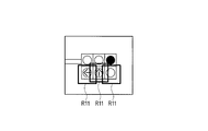
- the search area setting unit 23 sets the arrow search area R11 based on the traffic signal information acquired from the traffic signal information detection unit 26, as shown in FIG. Since the search area setting unit 23 acquires the information of the arrow traffic signal such as the position, the direction, and the size as the traffic signal information from the map database, the search area setting unit 23 has a smaller range than the arrow search area R7 of the first embodiment. An arrow search area R11 can be set.
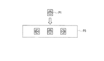
- the arrow rotation pattern generation unit 24 generates an arrow rotation pattern using the traffic signal information acquired from the map database. For example, when it is determined from the map database that the direction of the arrow signal of the traffic light existing at the approaching intersection in the traveling direction of the host vehicle is the three directions of the left and right direction and the straight direction, the arrow rotation pattern generation unit 24 As shown, the arrow reference pattern P1 is rotated by 90 degrees to generate a three-direction arrow rotation pattern P3, which is output to the arrow signal detection unit 25. In other words, the arrow rotation pattern generation unit 24 generates the arrow rotation pattern P3 based on the direction of the arrow signal registered in the map database of the traffic signal existing at the approaching intersection in the traveling direction of the host vehicle.
- a plurality of arrow rotation patterns P3 having different angles rotated from 90 degrees are assumed in consideration of the fact that the image is not captured at an accurate angle depending on the direction of the vehicle with respect to the arrow signal. May be generated. Thereby, the arrow rotation pattern generation unit 24 does not generate an unnecessary arrow rotation pattern.
- step S ⁇ b> 501 the traffic signal information detection unit 26 approaches an approaching intersection where the host vehicle approaches based on the posture of the host vehicle detected by the posture detection unit 40 and the current position and traveling direction of the host vehicle detected by the navigation device 50. Is detected.
- step S502 the traffic signal information detection unit 26 determines whether there is a traffic signal at the approaching intersection using the information in the map database. If there is a traffic light at the approaching intersection (Yes in step S502), the process proceeds to step S503. On the other hand, when there is no traffic light at the approaching intersection (No in step S502), a series of processing ends.
- step S ⁇ b> 503 the traffic signal information detection unit 26 determines whether or not the host vehicle with respect to the approaching intersection is based on the posture of the host vehicle detected by the posture detection unit 40 and the current position and traveling direction of the host vehicle detected by the navigation device 50. Detect the approach direction.
- step S504 the traffic signal information detection unit 26 detects the traffic signal information of the approaching intersection from the map database information, and outputs the detected traffic signal information to the traffic signal detection unit 21, the search area setting unit 23, and the arrow rotation pattern generation unit 24. To do.
- steps S601 to S602 steps S605 to S606, and steps S607 to S609 are the same as the operations in steps S101 to 102, steps S103 to S104, and steps S105 to S107 in FIG. 7, respectively. Detailed description will be omitted, and only differences will be described.
- step S603 the traffic signal detector 21 determines whether or not the traffic signal information has been acquired from the traffic signal information detector 26.
- the process proceeds to step S604.
- the process proceeds to step S605.
- step S604 the traffic signal detector 21 sets the search area R10 in the captured image based on the acquired traffic signal information.
- steps S701 to S703, S705, and S707 are the same as the operations in steps S301 to S303, S305, and S304 in FIG. 9, respectively, so that detailed description is omitted and only the differences are described. To do.
- step S704 the search area setting unit 23 determines whether or not the traffic signal information has been acquired from the traffic signal information detection unit 26. If the traffic signal detector 21 acquires traffic signal information (Yes in step S704), the process proceeds to step S706. On the other hand, when the traffic signal detector 21 has not acquired the traffic signal information (No in step S704), the process proceeds to step S707.
- step S706 the traffic signal detector 21 sets the arrow search region R11 in the captured image based on the acquired traffic signal information.
- FIG. 19 An example of the operation of the arrow signal detection unit 25 is the same as that of the flowchart of FIG. 10, but in the second embodiment, as shown in FIG. 19, the number of arrow rotation patterns P3 is three. There are fewer than seven of the arrow rotation patterns P2. That is, in the second embodiment, since pattern matching is performed with a small number of patterns, the system load related to pattern matching is reduced.
- the method for setting the control numbers n and p is the same as in the first embodiment.
- the arrow traffic light detection device 2 acquires the information of the arrow traffic light such as the position, the direction, and the size from the map database as the traffic signal information existing at the intersection in the traveling direction of the host vehicle. And since the arrow signal apparatus detection apparatus 2 produces
- the three-lamp type traffic signal has been described, but the present invention can also be applied to other traffic signals (for example, a traffic signal having only an arrow signal light).
- the traffic light detection unit 21 detects the traveling region R12 of the host vehicle from the white line, the stop line, and the curb as shown in FIG. 20, and above the detected traveling region R12.
- a rectangular normal search region R1 can be set.
- the arrow rotation pattern generation unit 24 further uses arrows at a plurality of different angles.
- the rotation patterns P2 and P3 may be generated.
- the plurality of different angles do not need to be equally spaced, such as every 45 degrees, and need not be omnidirectional, such as an angle width of 360 degrees, and can be arbitrarily set.
Landscapes
- Physics & Mathematics (AREA)
- General Physics & Mathematics (AREA)
- Engineering & Computer Science (AREA)
- Computer Vision & Pattern Recognition (AREA)
- Theoretical Computer Science (AREA)
- Traffic Control Systems (AREA)
- Image Analysis (AREA)
Abstract
単一の手法を用いて矢印信号の向きを検出する矢印信号機検出装置及び矢印信号機検出方法を提供する。本発明に係る矢印信号機検出装置は、自車両の周囲を撮像する撮像部(10)と、矢印形状パターンを所定の角度で回転させた複数の異なる方向の矢印回転パターンを生成する矢印回転パターン生成部(24)と、撮像部(10)によって撮像された画像に対して、画像上の位置と矢印回転パターンとを変えながらパターンマッチングを行い、矢印信号を検出する矢印信号検出部(25)を備える。
Description
本発明は、矢印信号機検出装置及び矢印信号機検出方法に関する。
この種の技術として、特許文献1では、自車両から信号機までの距離を3段階(近距離、中距離、遠距離)で分類し、各段階で異なる手法を用いて矢印信号を検出する。
しかしながら、特許文献1のように自車両から信号機までの距離に応じて矢印信号の検出方法を変更すると処理が複雑になり、矢印信号の検出に係るシステム負荷が増加するおそれがある。
本発明は、上記問題に鑑みて成されたものであり、その目的は、単一の手法を用いて矢印信号の向きを検出することによりシステム負荷を軽減できる矢印信号機検出装置及び矢印信号機検出方法を提供することである。
本発明の一態様に係る矢印信号機検出装置は、撮像部を用いて自車両の周囲を撮像し、矢印形状パターンを所定の角度で回転させた複数の異なる方向の矢印回転パターンを生成する。続いて矢印信号機検出装置は、撮像した画像に対して、画像上の位置と矢印回転パターンとを変えながらパターンマッチングを行い、矢印信号を検出する。
以下、本発明の実施形態について、図面を参照して説明する。図面の記載において同一部分には同一符号を付して説明を省略する。また、本実施形態では、種々の信号機のうち、3灯型の信号機を取り上げて説明する。
[第1実施形態]
図1を参照して、本発明の第1実施形態に係る矢印信号機検出装置1の構成を説明する。図1に示すように、矢印信号機検出装置1は、カメラ10と、信号機検出装置20とを備える。
図1を参照して、本発明の第1実施形態に係る矢印信号機検出装置1の構成を説明する。図1に示すように、矢印信号機検出装置1は、カメラ10と、信号機検出装置20とを備える。
カメラ10(撮像部)は、CCDやCMOSなどの撮像素子を有したカメラと画像処理部を備える。カメラ10は、自車両に設置され、自車両の周囲を時間的に連続して撮像する。画像処理部は、撮像した画像(以下、単に撮像画像という)に対して所定の画像処理を行い、信号機検出装置20に出力する。
信号機検出装置20は、例えばCPU、ROM、RAMおよびそれらを接続するデータバスと入出力インターフェースから構成されるコンピュータであり、ROMに格納されたプログラムに従い、CPUが所定の処理を行う。
信号機検出装置20は、これを機能的に捉えた場合、信号機検出部21と、色識別部22と、探索領域設定部23と、矢印回転パターン生成部24と、矢印信号検出部25に分類することができる。
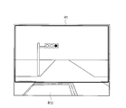
信号機検出部21は、撮像画像から信号機の位置及び大きさを検出し、検出結果を色識別部22に出力する。具体的には、信号機検出部21は、図2(a)に示すように、撮像画像の上方の路面よりも高い領域の信号機が存在する領域に信号機を探索するための矩形の通常探索領域R1を設定する。なお、信号機検出部21は、ナビゲーション装置50の地図情報から進行方向に存在する信号機の領域を推定して、通常探索領域R1を設定することもできる。
続いて、信号機検出部21は、図2(b)に示すように、予め学習させた信号機モデルをマッチング領域R2に適用する。そして、信号機検出部21は、図2(b)の点線矢印に示すように、通常探索領域R1の左上から右下に向かって左右にマッチング領域R2の座標を移動させながらパターンマッチングを行い、信号機を検出する。なお、信号機検出部21は、マッチング領域R2の大きさを変えながらパターンマッチングを行うことができる。そして、信号機検出部21は、検出した信号機の位置及び大きさを色識別部22に出力する。
また、信号機検出部21は、図3に示すように、撮像画像に優先探索領域R3を設定することができる。優先探索領域R3とは、前回の撮像画像上で検出された信号機の位置及び大きさの情報を用いて、今回撮像された撮像画像に対して設定する領域である。
優先探索領域R3は、例えば、前回の撮像画像上で検出された信号機の位置及び大きさの情報から、前回から今回の撮像までの自車両の動き(速度、方向)をもとに、今回の撮像画像上の信号機の位置及び大きさを予測することで、求めることができる。自車両の速度によってどのように変化するかについては、予め実験やシミュレーションを通じて求めることができる。
このように優先探索領域R3は、撮像画像上で検出した信号機の位置及び大きさの情報を用いて設定されるため、通常探索領域R1より小さい領域となる。これにより、マッチング領域R2を移動させる範囲は、通常探索領域R1より小さくなる。したがって、信号機検出部21は、優先探索領域R3を設定することにより信号機の検出に係るシステム負荷を低減することができる。
色識別部22は、撮像画像と信号機検出部21の出力から信号機の灯火の色を識別し、識別結果を探索領域設定部23に出力する。具体的には、色識別部22は、図4(a)~図4(c)に示すように、信号機検出部21によって検出された信号機に対し、3つの色識別領域R4~色識別領域R6を設定する。より詳しくは、色識別部22は、信号機の横方向の長さをwとして、信号機の左右及び中央にr×w/3となる長さの色識別領域R4~色識別領域R6を設定する。rは、信号機の大きさに応じて変化する係数である。
続いて、色識別部22は、設定した色識別領域R4~R6の画素値をHSV色空間に割り付ける。HSV色空間では赤、黄、緑の領域が予め設定されている。色識別部22は、赤、黄、緑の各領域に割り付けた画素値のうち、画素値の数が最も多い領域を灯火の色として識別する。そして、色識別部22は、識別した信号機の灯火の色を探索領域設定部23に出力する。
矢印回転パターン生成部24は、図5に示すように、予め生成した矢印形状の矢印基準パターンP1を45度ずつ回転させて7方向の矢印回転パターンP2を生成する。矢印回転パターン生成部24は、矢印基準パターンP1の生成する基準パターン生成部を含んでおり、その生成方法を説明すると、まず矢印回転パターン生成部24は、信号機検出装置20に保存されている複数の矢印信号の画像を取得し、取得した画像の矢印信号の向きを上方向(直進方向)に揃える。
続いて、基準パターン生成部は、向きを揃えた画像を用いて機械学習を行い、矢印信号を検出するのに特化した1種類の矢印基準パターンP1を生成する。そして、矢印回転パターン生成部24は、このように生成した矢印基準パターンP1を用いて矢印回転パターンP2を生成し、矢印信号検出部25に出力する。
探索領域設定部23は、色識別部22の出力から信号機に付帯する矢印信号を探索する領域を設定し、設定結果を矢印信号検出部25に出力する。具体的には、探索領域設定部23は、図6(a)に示すように、撮像画像上の信号機の位置から所定距離または所定画素だけ離れた矩形の矢印探索領域R7(第2探索領域に相当)を設定する。例えば、所定距離または所定画素は、信号機の灯火一つ分の大きさとして設定することができる。撮像画像上の信号機の位置は、信号機検出部21が通常探索領域R1よりパターンマッチングを行い、検出した信号機の座標を用いることができる。
また、探索領域設定部23は、後述する矢印信号検出部25から取得した矢印信号の位置及び大きさの情報を用いて、図6(b)に示すように、既存矢印領域R8(第1探索領域に相当)を設定することができる。既存矢印領域R8とは、前回の撮像画像上で検出された矢印信号の位置及び大きさの情報を用いて、今回撮像された撮像画像に対して設定する領域である。既存矢印領域R8は、上述した優先探索領域R3と同様に、前回の撮像画像上で検出された矢印信号の位置及び大きさの情報から、前回から今回の撮像までの自車両の動き(速度、方向)をもとに、今回の撮像画像上の信号機の位置及び大きさを予測することで、求めることができる。例えば、既存矢印領域R8の大きさは、検出された矢印信号灯の周囲に信号機の灯火一つ分の大きさとして設定することができる。
矢印信号検出部25(パターン選択部)は、図6(c)に示すように、探索領域設定部23によって設定された矢印探索領域R7に対し、矢印回転パターンP2を矢印マッチング領域R9に適用する。そして、矢印信号検出部25は、図6(c)の点線矢印に示すように、矢印探索領域R7の左上の開始位置から右下に向かって左右に矢印マッチング領域R9の座標を変えて移動させながら、かつ、矢印回転パターンP2を異なる回転角度に変えながら、パターンマッチングを行い、矢印信号を検出する。より詳しくは、矢印信号検出部25は、矢印マッチング領域R9の座標を、例えば、1画素だけ横方向に画像上の位置を変えて移動させ、その後、矢印回転パターンP2を1つずつ異なる回転角度に選択してパターンマッチングを行い、すべての矢印回転パターンP2のパターンマッチングを行った上、次の座標へ移動させる。また、矢印信号検出部25は、矢印マッチング領域R9の座標を変えて移動させる際に、一旦、1つの矢印回転パターンP2を用いて、矢印探索領域R7の右下端までパターンマッチングを行った上、別の異なる回転角度の矢印回転パターンP2を選択して、再度、矢印探索領域R7の左上の開始位置から右下に向かって左右に矢印マッチング領域R9の座標を変えて移動させてもよい。なお、矢印信号検出部25は、矢印マッチング領域R9の大きさを変えながらパターンマッチングを行うことができる。そして、矢印信号検出部25は、検出した矢印信号の位置、向き、大きさなどの矢印信号情報を探索領域設定部23に出力する。
また、探索領域設定部23によって既存矢印領域R8が設定されている場合、矢印信号検出部25は、既存矢印領域R8上でパターンマッチングを行う。既存矢印領域R8は、矢印探索領域R7より小さいため矢印マッチング領域R9を移動させる範囲は、矢印探索領域R7より小さくなる。したがって、矢印信号検出部25は、既存矢印領域R8を用いることにより矢印信号の検出に係るシステム負荷を低減することができる。また、既存矢印領域R8を用いる場合、前回の撮像画像で矢印信号の向きが検出されているため、矢印信号検出部25は、検出した矢印信号の向きに一致する矢印回転パターンP2を選択してパターンマッチングを行うことができる。このように既存矢印領域R8を用いる場合、矢印信号検出部25は、複数の矢印回転パターンP2を用いることなく、前回から継続して点灯している矢印信号を検出できるため、システム負荷を低減することができる。
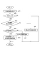
次に、図7~図10のフローチャートを参照して、矢印信号機検出装置1に係る信号機検出部21、色識別部22、探索領域設定部23、及び矢印信号検出部25の動作例を説明する。まず最初に、図7のフローチャートを参照して、信号機検出部21の動作例を説明する。
ステップS101において、信号機検出部21は、カメラ10から撮像画像を取得する。
ステップS102において、信号機検出部21は、優先探索領域R3が作成されているか否かを判断する。優先探索領域R3が作成されていない場合(ステップS102でNo)、処理がステップS103に進む。一方、優先探索領域R3が作成されている場合(ステップS102でYes)、処理がステップS104に進む。
ステップS103において、信号機検出部21は、撮像画像に通常探索領域R1を設定する。
ステップS104において、信号機検出部21は、作成された優先探索領域R3を設定する。
ステップS105において、信号機検出部21は、通常探索領域R1内または優先探索領域R3内で、信号機モデルを用いてパターンマッチングを行う。パターンマッチングにより信号機が検出された場合(ステップS105でYes)、処理がステップS106に進む。一方、信号機が検出されなかった場合(ステップS105でNo)、一連の処理が終了する。
ステップS106において、信号機検出部21は、検出した信号機の位置及び大きさや車速などから次の撮像画像に設定する優先探索領域R3を作成する。
ステップS107において、信号機検出部21は、信号機検出結果を色識別部22に出力し、一連の処理が終了する。
次に、図8のフローチャートを参照して、色識別部22の動作例を説明する。
ステップS201において、色識別部22は、カメラ10から撮像画像を取得する。
ステップS202において、色識別部22は、信号機検出部21から信号機の位置及び大きさを取得する。
ステップS203において、色識別部22は、取得した信号機に色識別領域R4~R6を設定する。
ステップS204において、色識別部22は、設定した色識別領域R4~R6の画素値をHSV色空間に割り付ける。
ステップS205において、色識別部22は、赤、黄、緑の各領域に割り付けた画素値のうち、画素値の数が最も多い領域が緑であるか否かを判断する。画素値の数が最も多い領域が緑である場合(ステップS205でYes)、処理がステップS206に進む。一方、画素値の数が最も多い領域が緑でない場合(ステップS205でNo)、処理がステップS207に進む。
ステップS207において、色識別部22は、赤、黄、緑の各領域に割り付けた画素値のうち、画素値の数が最も多い領域が黄であるか否かを判断する。画素値の数が最も多い領域が黄である場合(ステップS207でYes)、処理がステップS208に進む。一方、画素値の数が最も多い領域が黄でない場合(ステップS207でNo)、処理がステップS209に進む。
ステップS206において、色識別部22は、信号機の灯火は緑色であると判断する。また、ステップS208において、色識別部22は、信号機の灯火は黄色であると判断する。また、ステップS209において、色識別部22は、信号機の灯火は赤色であると判断する。
ステップS210において、色識別部22は、信号機の灯火の識別結果を探索領域設定部23に出力し、一連の処理が終了する。
次に、図9のフローチャートを参照して、探索領域設定部23の動作例を説明する。
ステップS301において、探索領域設定部23は、信号機の灯火の色を色識別部22から取得する。
ステップS302において、探索領域設定部23は、信号機の灯火が黄色または赤色であるか否かを判断する。信号機の灯火が黄色または赤色である場合(ステップS302でYes)、処理がステップS303に進む。一方、信号機の灯火が黄色でも赤色でもない場合、すなわち緑色である場合(ステップS302でNo)、一連の処理が終了する。
ステップS303において、探索領域設定部23は、矢印信号検出部25から矢印信号情報を取得したか否かを判断する。探索領域設定部23が矢印信号情報を取得していない場合(ステップS303でNo)、処理がステップS304に進む。一方、探索領域設定部23が矢印信号情報を取得した場合(ステップS303でYes)、処理がステップS305に進む。
ステップS304において、探索領域設定部23は、撮像画像に矢印探索領域R7を設定する。
ステップS305において、探索領域設定部23は、取得した矢印信号情報を用いて既存矢印領域R8を設定する。
次に、図10のフローチャートを参照して、矢印信号検出部25の動作例を説明する。
ステップS401において、矢印信号検出部25は、カメラ10から撮像画像を取得する。
ステップS402において、矢印信号検出部25は、探索領域設定部23から矢印探索領域R7または既存矢印領域R8を取得する。
ステップS403において、矢印信号検出部25は、取得した矢印探索領域R7または既存矢印領域R8に矢印マッチング領域R9を適用する。そして、矢印信号検出部25は、矢印マッチング領域R9の座標を移動させて、パターンマッチングさせる領域を更新する。
ステップS404において、矢印信号検出部25は、矢印回転パターンP2から1つを選択してパターンマッチングを行う。矢印回転パターンP2から1つを選択する方法として、図11に示すように、左端の矢印回転パターンP2から順に制御番号nを0から6まで割り当て、割り当てた制御番号の順に選択する方法がある。また、図11に示すように、重み付けをした制御番号pを用いてもよい。重み付けは、例えば、矢印信号に採用されている向きが多い順に行うことができる。本実施形態では、左右方向及び直進方向の制御番号pを1とし、左右斜め前進方向の制御番号pを2とし、左右斜め後進方向の制御番号pを3としている。制御番号pを用いて矢印回転パターンP2から1つを選択する場合は、1,2,3の順に選択することができる。
ステップS405において、矢印信号検出部25は、矢印信号を検出したか否かを判断する。矢印信号検出部25が矢印信号を検出した場合(ステップS405でYes)、処理がステップS406に進む。一方、矢印信号検出部25矢印信号を検出していない場合(ステップS405でNo)、処理がステップS407に進む。
ステップS406において、矢印信号検出部25は、矢印信号の位置、向き、大きさなどの矢印信号情報を記録する。また、矢印信号検出部25は、記録した矢印信号情報を探索領域設定部23に出力する。
ステップS407において、矢印信号検出部25は、矢印回転パターンP2の選択回数が設定値(本実施形態では図11に示すように7つ)以上か否かを判断する。選択回数が設定値以上である場合(ステップS407でYes)、処理がステップS408に進む。一方、選択回数が設定値より小さい場合(ステップS407でNo)、処理がステップS404に戻る。
ステップS408において、矢印信号検出部25は、矢印マッチング領域R9が矢印探索領域R7の端に到達したか否かを判断する。矢印マッチング領域R9が矢印探索領域R7の端に到達した場合(ステップS408でYes)、一連の処理が終了する。一方、矢印マッチング領域R9が矢印探索領域R7の端に到達していない場合(ステップS408でNo)、処理がステップS403に戻る。
以上説明したように、第1実施形態に係る矢印信号機検出装置1によれば、以下の作用効果が得られる。
矢印信号機検出装置1は、撮像画像上に矢印探索領域R7を設定する。矢印信号機検出装置1は、矢印形状パターンを所定の角度で回転させた複数の異なる方向の矢印回転パターンP2を生成し、設定した矢印探索領域R7内の画像上の位置と矢印回転パターンP2とを変えながらパターンマッチングを行い、矢印信号を検出する。これにより、矢印信号機検出装置1は、矢印信号の位置、向き、及び大きさを同時に検出することができる。また、矢印信号機検出装置1は、単一の手法を用いて矢印信号を検出できるため、システム負荷を軽減できる。
また、矢印信号機検出装置1は、1種類の矢印基準パターンP1を所定の角度で回転させて矢印回転パターンP2を生成するため、矢印信号ごとの個別パターンの用意が不要となる。これにより、矢印信号機検出装置1は、パターンマッチングに係るコストを低減でき、さらにシステム負荷も軽減できる。
また、矢印信号機検出装置1は、検出した矢印信号に基づいて、次の撮像画像上で矢印信号を検出するための領域である既存矢印領域R8(第1探索領域に相当)を設定する。これにより、矢印信号機検出装置1は、効率よく矢印信号を検出できるため、システム負荷を軽減できる。
また、矢印信号機検出装置1は、検出した信号機に基づいて矢印探索領域R7(第2探索領域に相当)を設定する。矢印信号は、通常信号機の周囲に存在するため、矢印信号機検出装置1は、信号機の周囲を探索することにより、システム負荷を低減できる。
また、矢印信号機検出装置1は、矢印信号が点灯している可能性が高い黄信号または赤信号のときに矢印信号を検出し、緑信号のときは矢印信号を検出しないため、システム負荷を低減できる。
[第2実施形態]
次に、図12を参照して、本発明の第2実施形態に係る矢印信号機検出装置2の構成について説明する。第2実施形態が、第1実施形態と異なる点は、矢印信号機検出装置2が姿勢検出部40と、ナビゲーション装置50と、信号機情報検出部26をさらに備えることである。第1実施形態と重複する構成については符号を引用してその説明は省略することとし、以下、相違点を中心に説明する。
次に、図12を参照して、本発明の第2実施形態に係る矢印信号機検出装置2の構成について説明する。第2実施形態が、第1実施形態と異なる点は、矢印信号機検出装置2が姿勢検出部40と、ナビゲーション装置50と、信号機情報検出部26をさらに備えることである。第1実施形態と重複する構成については符号を引用してその説明は省略することとし、以下、相違点を中心に説明する。
姿勢検出部40は、自車両の姿勢を検出する装置であり、ヨーレート(車両重心の上下方向軸回りの回転角速度)を検出するヨーレートセンサや、操舵角を検出する舵角センサなどを備えている。
ナビゲーション装置50は、地図データベースを備え、GPS信号を受信して自車両の地図上の現在位置を検出する。地図データベースには、交差点に存在する信号機の位置及び大きさ、矢印信号の位置、向き、大きさなどの信号機情報が登録されている。
信号機情報検出部26は、姿勢検出部40により検出された自車両の姿勢と、ナビゲーション装置50により検出された自車両の現在位置および進行方向に基づき、自車両が接近する交差点(以下、単に接近交差点という)を検出する。そして、信号機情報検出部26は、地図データベースの情報を用いて、接近交差点に信号機が存在するか否かを判断する。
信号機情報検出部26は、接近交差点に信号機が存在すると判断した場合、図13に示すように、撮像画像に信号機を探索するための探索領域R10を設定する。そして、信号機情報検出部26は、探索領域R10の適用したマッチング領域R2を移動させながらパターンマッチングを行い、信号機を検出する。信号機情報検出部26は、地図データベースから信号機情報を取得しているため、第1実施形態の通常探索領域R1と比較して、範囲を小さくした探索領域R10を設定することができる。なお、姿勢検出部40が検出する車両姿勢やナビゲーション装置50が検出する車両位置には誤差が含まれるため、信号機情報検出部26は、この誤差を考慮して信号機の所定倍の大きさとなる探索領域R10を設定することができる。
信号機情報検出部26は、検出した信号機情報を信号機検出部21、矢印回転パターン生成部24、及び探索領域設定部23に出力する。
探索領域設定部23は、信号機情報検出部26から取得した信号機情報に基づいて、図14に示すように、矢印探索領域R11を設定する。探索領域設定部23は、地図データベースから信号機情報として位置、向き、大きさなどの矢印信号機の情報を取得しているため、第1実施形態の矢印探索領域R7と比較して、範囲を小さくした矢印探索領域R11を設定することができる。
矢印回転パターン生成部24は、地図データベースから取得した信号機情報を用いて矢印回転パターンを生成する。例えば、自車両の進行方向の接近交差点に存在する信号機の矢印信号の向きが左右方向及び直進方向の3方向であることが地図データベースから判明した場合、矢印回転パターン生成部24は、図15に示すように、矢印基準パターンP1を90度ずつ回転させて3方向の矢印回転パターンP3を生成し、矢印信号検出部25に出力する。すなわち、矢印回転パターン生成部24は、自車両の進行方向の接近交差点に存在する信号機の地図データベースに登録されている矢印信号の向きに基づいて、矢印回転パターンP3を生成する。矢印信号に対する車両の向きなどによって、撮像画像上では正確な角度でずれた形で撮像されないことを考慮して、90度から想定されるずれ角度で回転させた異なる角度の複数の矢印回転パターンP3を生成してもよい。これにより、矢印回転パターン生成部24は、不要な矢印回転パターンを生成することがなくなる。
次に、図16~図18のフローチャートを参照して、矢印信号機検出装置2に係る信号機情報検出部26、信号機検出部21、色識別部22の動作例を説明する。まず最初に、図16のフローチャートを参照して、信号機情報検出部26の動作例を説明する。
ステップS501において、信号機情報検出部26は、姿勢検出部40により検出された自車両の姿勢と、ナビゲーション装置50により検出された自車両の現在位置および進行方向に基づき、自車両が接近する接近交差点を検出する。
ステップS502において、信号機情報検出部26は、地図データベースの情報を用いて接近交差点に信号機が存在するか否かを判断する。接近交差点に信号機が存在する場合(ステップS502でYes)、処理がステップS503に進む。一方、接近交差点に信号機が存在しない場合(ステップS502でNo)、一連の処理が終了する。
ステップS503において、信号機情報検出部26は、姿勢検出部40により検出された自車両の姿勢と、ナビゲーション装置50により検出された自車両の現在位置および進行方向とに基づき、接近交差点に対する自車両の進入方向を検出する。
ステップS504において、信号機情報検出部26は、地図データベースの情報から接近交差点の信号機情報を検出し、検出した信号機情報を信号機検出部21、探索領域設定部23、及び矢印回転パターン生成部24に出力する。
次に、図17のフローチャートを参照して、信号機検出部21の動作例を説明する。ただし、ステップS601~ステップS602,ステップS605~ステップS606,ステップS607~ステップS609の動作はそれぞれ、図7のステップS101~102,ステップS103~ステップS104,ステップS105~ステップS107の動作と同じであるため詳細な説明を省略し、相違点のみ説明する。
ステップS603において、信号機検出部21は、信号機情報検出部26から信号機情報を取得したか否かを判断する。信号機検出部21が信号機情報を取得した場合(ステップS603でYes)、処理がステップS604に進む。一方、信号機検出部21が信号機情報を取得していない場合(ステップS603でNo)、処理がステップS605に進む。
ステップS604において、信号機検出部21は、取得した信号機情報に基づいて撮像画像に探索領域R10を設定する。
次に、図18のフローチャートを参照して、探索領域設定部23の動作例を説明する。ただし、ステップS701~ステップS703,ステップS705,ステップS707の動作はそれぞれ、図9のステップS301~303,ステップS305,ステップS304の動作と同じであるため、詳細な説明を省略し、相違点のみ説明する。
ステップS704において、探索領域設定部23は、信号機情報検出部26から信号機情報を取得したか否かを判断する。信号機検出部21が信号機情報を取得した場合(ステップS704でYes)、処理がステップS706に進む。一方、信号機検出部21が信号機情報を取得していない場合(ステップS704でNo)、処理がステップS707に進む。
ステップS706において、信号機検出部21は、取得した信号機情報に基づいて撮像画像に矢印探索領域R11を設定する。
矢印信号検出部25の動作例は、図10のフローチャートと同様であるが、第2実施形態では、図19に示すように、矢印回転パターンP3のパターン数が3つであり、第1実施形態の矢印回転パターンP2の7つより少ない。すなわち、第2実施形態では、少ないパターン数でパターンマッチングを行うため、パターンマッチングに係るシステム負荷が軽減される。なお、制御番号n及びpの設定方法は第1実施形態と同じである。
以上説明したように、第2実施形態に係る矢印信号機検出装置2によれば、以下の作用効果が得られる。
矢印信号機検出装置2は、自車両の進行方向の交差点に存在する信号機情報として位置、向き、大きさなどの矢印信号機の情報を地図データベースから取得する。そして、矢印信号機検出装置2は、取得した矢印信号の向きに基づいて矢印回転パターンP3を生成するため、不要な矢印回転パターンを生成することがなくなる。これにより、矢印信号機検出装置2は、パターンマッチングに要する時間を短縮でき、システム負荷を低減できる。
上記のように、本発明の実施形態を記載したが、この開示の一部をなす論述及び図面はこの発明を限定するものであると理解すべきではない。この開示から当業者には様々な代替実施の形態、実施例及び運用技術が明らかとなろう。
例えば、第1及び第2実施形態では3灯型の信号機を取り上げて説明したが、本発明はその他の信号機(例えば、矢印信号灯のみの信号機)にも適用できる。
また、通常探索領域R1の設定方法の一例として、信号機検出部21は、図20に示すように、白線、停止線、縁石から自車両の走行領域R12を検出し、検出した走行領域R12の上方に矩形の通常探索領域R1を設定することができる。
また、矢印信号は、矢印信号に対する車両の向きなどによって、撮像画像上では正確に45度ずれた形で撮像されないことを考慮して、矢印回転パターン生成部24は、さらに複数の異なる角度の矢印回転パターンP2及びP3を生成してもよい。複数の異なる角度は、45度毎などの等間隔である必要はなく、360度の角度幅などの全方向である必要もなく、任意に設定することができる。
1 矢印信号機検出装置
2 矢印信号機検出装置
10 カメラ
20 信号機検出装置
21 信号機検出部
22 色識別部
23 探索領域設定部(第1探索領域設定部および第2探索領域設定部に相当)
24 矢印回転パターン生成部
25 矢印信号検出部
26 信号機情報検出部
40 姿勢検出部
50 ナビゲーション装置
2 矢印信号機検出装置
10 カメラ
20 信号機検出装置
21 信号機検出部
22 色識別部
23 探索領域設定部(第1探索領域設定部および第2探索領域設定部に相当)
24 矢印回転パターン生成部
25 矢印信号検出部
26 信号機情報検出部
40 姿勢検出部
50 ナビゲーション装置
Claims (7)
- 自車両の周囲を撮像する撮像部と、
矢印形状パターンを所定の角度で回転させた複数の異なる方向の矢印回転パターンを生成する矢印回転パターン生成部と、
前記撮像部によって撮像された画像に対して、前記画像上の位置と前記矢印回転パターンとを変えながらパターンマッチングを行い、矢印信号を検出する矢印信号検出部と
を備えることを特徴とする矢印信号機検出装置。 - 信号機ごとに少なくとも前記矢印信号の向きが登録された地図データベースと、
前記地図データベースより取得した前記矢印信号の向きに基づいて前記矢印回転パターンを選択するパターン選択部とをさらに備え、
前記矢印信号検出部は、前記パターン選択部によって選択された前記矢印回転パターンを用いて前記パターンマッチングを行うことを特徴とする請求項1に記載の矢印信号機検出装置。 - 予め取得した複数の矢印信号の画像を用いて1つの矢印形状の基準パターンを生成する基準パターン生成部をさらに備え、
前記矢印信号検出部は、前記基準パターン生成部によって生成された前記基準パターンを所定の角度で回転させた複数の異なる方向の矢印形状パターンを用いて、前記パターンマッチングを行うことを特徴とする請求項1または2に記載の矢印信号機検出装置。 - 前記矢印信号検出部によって前記矢印信号が検出された場合に、前記矢印信号が検出された画像上の位置に基づいて第1探索領域を設定する第1探索領域設定部をさらに備え、
前記矢印信号検出部は、前記矢印信号を検出した場合に、検出した前記矢印信号の向きに基づいて前記矢印回転パターンを選択して前記第1探索領域内で前記パターンマッチングを行うことを特徴とする請求項1~3のいずれか1項に記載の矢印信号機検出装置。 - 前記撮像部によって撮像された画像から信号機を検出する信号機検出部と、
前記信号機検出部によって前記信号機が検出された画像上の位置に基づいて第2探索領域を設定する第2探索領域設定部とをさらに備え、
前記矢印信号検出部は、前記第2探索領域設定部によって設定された第2探索領域内でパターンマッチングを行い、前記信号機に付帯する矢印信号を検出することを特徴とする請求項1~4のいずれか1項に記載の矢印信号機検出装置。 - 前記信号機検出部は、検出した信号機の灯火の色を検出し、
前記矢印信号検出部は、前記信号機検出部によって検出された灯火の色が赤または黄の場合に前記パターンマッチングを行うことを特徴とする請求項5に記載の矢印信号機検出装置。 - 自車両の周囲を撮像し、
矢印形状パターンを所定の角度で回転させた複数の異なる方向の矢印回転パターンを生成し、
撮像した画像に対して、前記画像上の位置と前記矢印回転パターンとを変えながらパターンマッチングを行い、矢印信号を検出することを特徴とする矢印信号機検出方法。
Priority Applications (1)
| Application Number | Priority Date | Filing Date | Title |
|---|---|---|---|
| PCT/JP2015/063729 WO2016181519A1 (ja) | 2015-05-13 | 2015-05-13 | 矢印信号機検出装置及び矢印信号機検出方法 |
Applications Claiming Priority (1)
| Application Number | Priority Date | Filing Date | Title |
|---|---|---|---|
| PCT/JP2015/063729 WO2016181519A1 (ja) | 2015-05-13 | 2015-05-13 | 矢印信号機検出装置及び矢印信号機検出方法 |
Publications (1)
| Publication Number | Publication Date |
|---|---|
| WO2016181519A1 true WO2016181519A1 (ja) | 2016-11-17 |
Family
ID=57248863
Family Applications (1)
| Application Number | Title | Priority Date | Filing Date |
|---|---|---|---|
| PCT/JP2015/063729 Ceased WO2016181519A1 (ja) | 2015-05-13 | 2015-05-13 | 矢印信号機検出装置及び矢印信号機検出方法 |
Country Status (1)
| Country | Link |
|---|---|
| WO (1) | WO2016181519A1 (ja) |
Cited By (5)
| Publication number | Priority date | Publication date | Assignee | Title |
|---|---|---|---|---|
| CN112183427A (zh) * | 2020-10-10 | 2021-01-05 | 厦门理工学院 | 一种箭形交通信号灯候选图像区域的快速提取方法 |
| CN114944073A (zh) * | 2021-02-16 | 2022-08-26 | 本田技研工业株式会社 | 地图生成装置和车辆控制装置 |
| CN117292360A (zh) * | 2023-11-24 | 2023-12-26 | 福思(杭州)智能科技有限公司 | 交通信号灯识别方法和装置、存储介质及电子设备 |
| JP2024095226A (ja) * | 2022-12-28 | 2024-07-10 | トヨタ自動車株式会社 | 灯火状態認識装置 |
| JP2024105411A (ja) * | 2016-12-09 | 2024-08-06 | トムトム グローバル コンテント ベスローテン フエンノートシャップ | ビデオベースの位置決め及びマッピングの方法及びシステム |
Citations (3)
| Publication number | Priority date | Publication date | Assignee | Title |
|---|---|---|---|---|
| JP2008242987A (ja) * | 2007-03-28 | 2008-10-09 | Aisin Aw Co Ltd | 運転支援方法及び運転支援装置 |
| JP2009043068A (ja) * | 2007-08-09 | 2009-02-26 | Honda Motor Co Ltd | 信号機認識装置 |
| JP2014193627A (ja) * | 2013-03-28 | 2014-10-09 | Koito Electric Industries Ltd | 信号機判別装置 |
-
2015
- 2015-05-13 WO PCT/JP2015/063729 patent/WO2016181519A1/ja not_active Ceased
Patent Citations (3)
| Publication number | Priority date | Publication date | Assignee | Title |
|---|---|---|---|---|
| JP2008242987A (ja) * | 2007-03-28 | 2008-10-09 | Aisin Aw Co Ltd | 運転支援方法及び運転支援装置 |
| JP2009043068A (ja) * | 2007-08-09 | 2009-02-26 | Honda Motor Co Ltd | 信号機認識装置 |
| JP2014193627A (ja) * | 2013-03-28 | 2014-10-09 | Koito Electric Industries Ltd | 信号機判別装置 |
Cited By (10)
| Publication number | Priority date | Publication date | Assignee | Title |
|---|---|---|---|---|
| JP2024105411A (ja) * | 2016-12-09 | 2024-08-06 | トムトム グローバル コンテント ベスローテン フエンノートシャップ | ビデオベースの位置決め及びマッピングの方法及びシステム |
| JP7769749B2 (ja) | 2016-12-09 | 2025-11-13 | トムトム グローバル コンテント ベスローテン フエンノートシャップ | ビデオベースの位置決め及びマッピングの方法及びシステム |
| CN112183427A (zh) * | 2020-10-10 | 2021-01-05 | 厦门理工学院 | 一种箭形交通信号灯候选图像区域的快速提取方法 |
| CN112183427B (zh) * | 2020-10-10 | 2023-05-30 | 厦门理工学院 | 一种箭形交通信号灯候选图像区域的快速提取方法 |
| CN114944073A (zh) * | 2021-02-16 | 2022-08-26 | 本田技研工业株式会社 | 地图生成装置和车辆控制装置 |
| CN114944073B (zh) * | 2021-02-16 | 2023-10-20 | 本田技研工业株式会社 | 地图生成装置和车辆控制装置 |
| JP2024095226A (ja) * | 2022-12-28 | 2024-07-10 | トヨタ自動車株式会社 | 灯火状態認識装置 |
| JP7835158B2 (ja) | 2022-12-28 | 2026-03-25 | トヨタ自動車株式会社 | 灯火状態認識装置 |
| CN117292360A (zh) * | 2023-11-24 | 2023-12-26 | 福思(杭州)智能科技有限公司 | 交通信号灯识别方法和装置、存储介质及电子设备 |
| CN117292360B (zh) * | 2023-11-24 | 2024-02-09 | 福思(杭州)智能科技有限公司 | 交通信号灯识别方法和装置、存储介质及电子设备 |
Similar Documents
| Publication | Publication Date | Title |
|---|---|---|
| JP7077910B2 (ja) | 区画線検出装置及び区画線検出方法 | |
| US10318782B2 (en) | Image processing device, image processing system, and image processing method | |
| JP6337961B2 (ja) | 信号機認識装置及び信号機認識方法 | |
| JP2005310140A (ja) | オブジェクトの認識及び/又は追跡方法 | |
| JP6139465B2 (ja) | 物体検出装置、運転支援装置、物体検出方法、および物体検出プログラム | |
| KR102569437B1 (ko) | 3차원 영상정보 기반 객체 추적 장치 및 방법 | |
| CN102745160A (zh) | 环境识别装置及环境识别方法 | |
| JPWO2010113239A1 (ja) | 画像統合装置および画像統合方法 | |
| CN107735826B (zh) | 信号机检测装置及信号机检测方法 | |
| EP3432259A1 (en) | Object detection device, object detection method, and program | |
| KR20200087354A (ko) | 자율주행용 데이터 라벨링 장치 및 방법 | |
| US20180300562A1 (en) | Processing device, object recognition apparatus, device control system, processing method, and computer-readable recording medium | |
| JP2020187474A (ja) | 走行車線認識装置、走行車線認識方法およびプログラム | |
| JP2006338272A (ja) | 車両挙動検出装置、および車両挙動検出方法 | |
| JP6795379B2 (ja) | 運転制御装置、運転制御方法及び運転制御プログラム | |
| JP7095559B2 (ja) | 区画線検出装置及び区画線検出方法 | |
| JP6608664B2 (ja) | 自車位置認識装置 | |
| JP2019053685A (ja) | 画像処理装置 | |
| EP4064220B1 (en) | Method, system and device for detecting traffic light for vehicle | |
| JP2021165916A (ja) | 傾斜角検出装置及び制御装置 | |
| JP2001076128A (ja) | 障害物検出装置及び方法 | |
| KR102424664B1 (ko) | 3차원 영상정보 기반 객체 추적 장치 및 방법 | |
| JP6918425B2 (ja) | 撮影画像に含まれる境界線を検出するための装置、方法、及びプログラム | |
| JP6683245B2 (ja) | 画像処理装置、画像処理方法、画像処理プログラム、物体認識装置及び機器制御システム | |
| US11769337B2 (en) | Traffic signal recognition method and traffic signal recognition device |
Legal Events
| Date | Code | Title | Description |
|---|---|---|---|
| 121 | Ep: the epo has been informed by wipo that ep was designated in this application |
Ref document number: 15891843 Country of ref document: EP Kind code of ref document: A1 |
|
| NENP | Non-entry into the national phase |
Ref country code: DE |
|
| 122 | Ep: pct application non-entry in european phase |
Ref document number: 15891843 Country of ref document: EP Kind code of ref document: A1 |
|
| NENP | Non-entry into the national phase |
Ref country code: JP |