WO2016178273A1 - 駆動制御装置、電子機器、駆動制御プログラム、及び駆動制御方法 - Google Patents
駆動制御装置、電子機器、駆動制御プログラム、及び駆動制御方法 Download PDFInfo
- Publication number
- WO2016178273A1 WO2016178273A1 PCT/JP2015/063115 JP2015063115W WO2016178273A1 WO 2016178273 A1 WO2016178273 A1 WO 2016178273A1 JP 2015063115 W JP2015063115 W JP 2015063115W WO 2016178273 A1 WO2016178273 A1 WO 2016178273A1
- Authority
- WO
- WIPO (PCT)
- Prior art keywords
- input
- drive control
- display
- vibration
- unit
- Prior art date
- Legal status (The legal status is an assumption and is not a legal conclusion. Google has not performed a legal analysis and makes no representation as to the accuracy of the status listed.)
- Ceased
Links
Images









Classifications
-
- G—PHYSICS
- G06—COMPUTING OR CALCULATING; COUNTING
- G06F—ELECTRIC DIGITAL DATA PROCESSING
- G06F3/00—Input arrangements for transferring data to be processed into a form capable of being handled by the computer; Output arrangements for transferring data from processing unit to output unit, e.g. interface arrangements
- G06F3/01—Input arrangements or combined input and output arrangements for interaction between user and computer
-
- G—PHYSICS
- G06—COMPUTING OR CALCULATING; COUNTING
- G06F—ELECTRIC DIGITAL DATA PROCESSING
- G06F3/00—Input arrangements for transferring data to be processed into a form capable of being handled by the computer; Output arrangements for transferring data from processing unit to output unit, e.g. interface arrangements
- G06F3/01—Input arrangements or combined input and output arrangements for interaction between user and computer
- G06F3/03—Arrangements for converting the position or the displacement of a member into a coded form
- G06F3/041—Digitisers, e.g. for touch screens or touch pads, characterised by the transducing means
-
- G—PHYSICS
- G06—COMPUTING OR CALCULATING; COUNTING
- G06F—ELECTRIC DIGITAL DATA PROCESSING
- G06F3/00—Input arrangements for transferring data to be processed into a form capable of being handled by the computer; Output arrangements for transferring data from processing unit to output unit, e.g. interface arrangements
- G06F3/01—Input arrangements or combined input and output arrangements for interaction between user and computer
- G06F3/048—Interaction techniques based on graphical user interfaces [GUI]
- G06F3/0487—Interaction techniques based on graphical user interfaces [GUI] using specific features provided by the input device, e.g. functions controlled by the rotation of a mouse with dual sensing arrangements, or of the nature of the input device, e.g. tap gestures based on pressure sensed by a digitiser
- G06F3/0488—Interaction techniques based on graphical user interfaces [GUI] using specific features provided by the input device, e.g. functions controlled by the rotation of a mouse with dual sensing arrangements, or of the nature of the input device, e.g. tap gestures based on pressure sensed by a digitiser using a touch-screen or digitiser, e.g. input of commands through traced gestures
Definitions
- the present invention relates to a drive control device, an electronic device, a drive control program, and a drive control method.
- an input guide that displays a touch panel, a detection unit that detects input coordinates, and an input guide that includes the selected character as a selected character and a candidate character that has a specific relationship with the selected character.
- a character input device that includes a display unit and an operation determination unit that determines whether it is a touch-down operation, a touch-up operation, or a flick operation.
- the guide button area of the selected character of the input guide is set as the fixed area
- the flick operation the area of the guide button of the candidate character specified at the position after the slide is set as the fixed area.
- a character input control unit that confirms the characters in the confirmed area as input characters is further provided.
- the character input control unit expands the determined area (see, for example, Patent Document 1).
- the user when the input coordinate moves from the input area of the selected character to the input area of the candidate character, the user visually recognizes the boundary between the two input areas and selects either the selected character or the candidate character. Select.
- a drive control apparatus includes a display unit, a top panel provided on a display surface side of the display unit and having an operation surface, and a position for detecting a position of an operation input performed on the operation surface.
- a drive control device for driving the vibration element of an electronic apparatus including a detection unit and a vibration element that generates vibration on the operation surface, wherein the symbol input unit is displayed on the display unit and used for inputting a symbol.
- a storage unit for storing data, and the operation surface A drive control unit that drives the vibration element with a drive signal that generates a natural vibration of a sound wave band, and the position of the operation input moves outside the first region and the plurality of second regions; or A drive control unit that drives the vibration element with a first vibration pattern so that the intensity of the natural vibration changes when the boundary between the second regions is reached, and the first region includes the first input unit.
- the first display area is equal to or includes the first display area and is larger than the first display area, and each of the plurality of second areas includes a plurality of second input sections. Two display areas, or an area that includes the plurality of second display areas and is larger than the plurality of second display areas.
- FIG. 3 is a diagram illustrating a cross section taken along the line AA of the electronic device illustrated in FIG. 2. It is a figure which shows the wave front formed in parallel with the short side of a top panel among the standing waves which arise in a top panel by the natural vibration of an ultrasonic band. It is a figure explaining a mode that the dynamic friction force applied to the fingertip which performs operation input changes with the natural vibration of the ultrasonic band produced on the top panel of an electronic device. It is a figure which shows the structure of the electronic device of embodiment. It is a figure which shows the input screen of the mail of an electronic device.
- FIG. 1 is a perspective view showing an electronic device 100 according to an embodiment.
- the electronic device 100 is, for example, a smartphone terminal or a tablet computer using a touch panel as an input operation unit. Since the electronic device 100 only needs to be a device having a touch panel as an input operation unit, the electronic device 100 is a device that is installed and used in a specific place such as a portable information terminal or an ATM (Automatic Teller Machine). May be.
- a smartphone terminal or a tablet computer using a touch panel as an input operation unit. Since the electronic device 100 only needs to be a device having a touch panel as an input operation unit, the electronic device 100 is a device that is installed and used in a specific place such as a portable information terminal or an ATM (Automatic Teller Machine). May be.
- ATM Automatic Teller Machine
- the input operation unit 101 of the electronic device 100 is provided with a display panel below the touch panel.
- Various buttons 102A or sliders 102B or the like (hereinafter referred to as GUI operation unit 102) using a GUI (Graphic User Interface) are provided on the display panel. Is displayed).
- the user of the electronic device 100 usually touches the input operation unit 101 with a fingertip in order to operate the GUI operation unit 102.
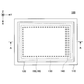
- FIG. 2 is a plan view showing the electronic device 100 according to the embodiment
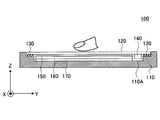
- FIG. 3 is a view showing a cross section taken along line AA of the electronic device 100 shown in FIG. 2 and 3, an XYZ coordinate system that is an orthogonal coordinate system is defined as shown.
- the electronic device 100 includes a housing 110, a top panel 120, a double-sided tape 130, a vibration element 140, a touch panel 150, a display panel 160, and a substrate 170.
- the housing 110 is made of, for example, resin, and as shown in FIG. 3, the substrate 170, the display panel 160, and the touch panel 150 are disposed in the recess 110 ⁇ / b> A, and the top panel 120 is bonded by the double-sided tape 130. .
- the top panel 120 is a thin flat plate member that is rectangular in plan view, and is made of transparent glass or reinforced plastic such as polycarbonate.
- the surface of the top panel 120 (the surface on the Z-axis positive direction side) is an example of an operation surface on which the user of the electronic device 100 performs operation input.
- the vibration element 140 is bonded to the surface on the negative side of the Z axis, and four sides in a plan view are bonded to the housing 110 with a double-sided tape 130.
- the double-sided tape 130 only needs to be able to bond the four sides of the top panel 120 to the housing 110, and does not have to be a rectangular ring as shown in FIG.
- the touch panel 150 is disposed on the Z-axis negative direction side of the top panel 120.
- the top panel 120 is provided to protect the surface of the touch panel 150. Further, another panel or a protective film may be provided on the surface of the top panel 120.
- the top panel 120 vibrates when the vibration element 140 is driven in a state where the vibration element 140 is bonded to the surface in the negative Z-axis direction.
- the top panel 120 is vibrated at the natural vibration frequency of the top panel 120 to generate a standing wave in the top panel 120.
- the vibration element 140 since the vibration element 140 is bonded to the top panel 120, it is actually preferable to determine the natural vibration frequency in consideration of the weight of the vibration element 140 and the like.
- the vibration element 140 is bonded along the short side extending in the X axis direction on the Y axis positive direction side on the Z axis negative direction side surface of the top panel 120.
- the vibration element 140 may be an element that can generate vibrations in an ultrasonic band.
- an element including a piezoelectric element such as a piezoelectric element can be used.
- the vibration element 140 is driven by a drive signal output from a drive control unit described later.
- the amplitude (intensity) and frequency of vibration generated by the vibration element 140 are set by the drive signal. Further, on / off of the vibration element 140 is controlled by a drive signal.
- an ultrasonic band means a frequency band about 20 kHz or more, for example.
- the frequency at which the vibration element 140 vibrates is equal to the frequency of the top panel 120. Therefore, the vibration element 140 is driven by a drive signal so as to vibrate at the natural frequency of the top panel 120. Is done.
- the touch panel 150 is disposed on the display panel 160 (Z-axis positive direction side) and below the top panel 120 (Z-axis negative direction side).
- the touch panel 150 is an example of a position detection unit that detects a position where the user of the electronic device 100 touches the top panel 120 (hereinafter referred to as an operation input position).
- GUI operation unit On the display panel 160 below the touch panel 150, various buttons and the like (hereinafter referred to as GUI operation unit) by GUI are displayed. For this reason, the user of the electronic device 100 usually touches the top panel 120 with a fingertip in order to operate the GUI operation unit.
- the touch panel 150 may be a position detection unit that can detect the position of an operation input to the user's top panel 120, and may be, for example, a capacitance type or resistance film type position detection unit.
- a mode in which the touch panel 150 is a capacitance type position detection unit will be described. Even if there is a gap between the touch panel 150 and the top panel 120, the capacitive touch panel 150 can detect an operation input to the top panel 120.
- the top panel 120 may be integrated with the touch panel 150.
- the surface of the touch panel 150 becomes the surface of the top panel 120 shown in FIGS. 2 and 3, and an operation surface is constructed.
- the structure which excluded the top panel 120 shown in FIG.2 and FIG.3 may be sufficient.
- the surface of the touch panel 150 constructs the operation surface.
- the member having the operation surface may be vibrated by the natural vibration of the member.
- the touch panel 150 when the touch panel 150 is a capacitance type, the touch panel 150 may be disposed on the top panel 120. Also in this case, the surface of the touch panel 150 constructs the operation surface. Moreover, when the touch panel 150 is a capacitance type, the structure which excluded the top panel 120 shown in FIG.2 and FIG.3 may be sufficient. Also in this case, the surface of the touch panel 150 constructs the operation surface. In this case, the member having the operation surface may be vibrated by the natural vibration of the member.
- the display panel 160 may be a display unit that can display an image, such as a liquid crystal display panel or an organic EL (Electroluminescence) panel.
- the display panel 160 is installed on the substrate 170 (Z-axis positive direction side) by a holder or the like (not shown) inside the recess 110A of the housing 110.
- the display panel 160 is driven and controlled by a driver IC (Integrated Circuit), which will be described later, and displays a GUI operation unit, images, characters, symbols, graphics, and the like according to the operation status of the electronic device 100.
- driver IC Integrated Circuit
- the substrate 170 is disposed inside the recess 110 ⁇ / b> A of the housing 110.
- a display panel 160 and a touch panel 150 are disposed on the substrate 170.
- the display panel 160 and the touch panel 150 are fixed to the substrate 170 and the housing 110 by a holder or the like (not shown).
- the drive control unit mounted on the substrate 170 drives the vibration element 140, and the top panel 120. Is vibrated at the frequency of the ultrasonic band.
- the frequency of this ultrasonic band is a resonance frequency of a resonance system including the top panel 120 and the vibration element 140 and causes the top panel 120 to generate a standing wave.
- the electronic device 100 provides tactile sensation to the user through the top panel 120 by generating a standing wave in the ultrasonic band.
- FIG. 4 is a diagram showing a wave front formed in parallel to the short side of the top panel 120 among standing waves generated in the top panel 120 due to the natural vibration of the ultrasonic band
- FIG. 4A is a side view.
- (B) is a perspective view. 4A and 4B, XYZ coordinates similar to those in FIGS. 2 and 3 are defined.
- the amplitude of the standing wave is exaggerated for ease of understanding.
- the vibration element 140 is omitted.
- 4A and 4B are waveforms when the number of periods k is 10, as an example.
- the period number k is 10.
- the natural frequency f is 33.5 [kHz].
- a drive signal having a frequency of 33.5 [kHz] may be used.
- the top panel 120 is a flat plate member.
- the vibration element 140 see FIGS. 2 and 3
- the top panel 120 is changed to (A) and (B) in FIG. By bending as shown, a standing wave is generated on the surface.
- the two vibration elements 140 may be used.
- the other vibration element 140 is bonded to the surface of the top panel 120 on the Z-axis negative direction side along the short side extending in the X-axis direction on the Y-axis negative direction side. That's fine.
- the two vibration elements 140 may be arranged so as to be axially symmetric with respect to a center line parallel to the two short sides of the top panel 120 as a symmetry axis.
- the two vibration elements 140 when the two vibration elements 140 are driven, they may be driven with the same phase when the number of periods k is an integer, and with opposite phases when the number of periods k is a decimal (a number including an integer part and a decimal part). It can be driven by.
- FIG. 5 is a diagram illustrating a state in which the dynamic friction force applied to the fingertip that performs the operation input changes due to the natural vibration of the ultrasonic band generated in the top panel 120 of the electronic device 100.
- the user performs an operation input to move the finger along the arrow from the back side of the top panel 120 to the near side while touching the top panel 120 with the fingertip.
- the vibration is turned on / off by turning on / off the vibration element 140 (see FIGS. 2 and 3).
- the natural vibration of the ultrasonic band occurs in the entire top panel 120 as shown in FIG. 4, but in FIGS. 5A and 5B, the user's finger is on the front side from the back side of the top panel 120.
- the operation pattern which switches on / off of a vibration during moving to is shown.
- the vibration is off when the user's finger is on the back side of the top panel 120, and the vibration is on in the middle of moving the finger to the near side.
- the vibration is turned on when the user's finger is on the back side of the top panel 120, and the vibration is turned off in the middle of moving the finger to the near side. Yes.
- the dynamic frictional force applied to the fingertip is large in the range indicated in gray on the back side of the top panel 120, and the dynamic frictional force applied to the fingertip is small in the range indicated in white on the near side of the top panel 120.
- the user who performs an operation input to the top panel 120 senses a decrease in the dynamic friction force applied to the fingertip and perceives the ease of slipping of the fingertip when the vibration is turned on. It will be. At this time, the user feels that a concave portion exists on the surface of the top panel 120 when the dynamic friction force decreases due to the surface of the top panel 120 becoming smoother.
- the dynamic friction force applied to the fingertip is small in the range shown in white on the front side of the top panel 120, and the dynamic friction force applied to the fingertip is large in the range shown in gray on the front side of the top panel 120.
- the user who performs an operation input to the top panel 120 senses an increase in the dynamic friction force applied to the fingertip when the vibration is turned off, You will perceive the feeling of being caught. And when a dynamic friction force becomes high because it becomes difficult to slip a fingertip, it will feel like a convex part exists in the surface of the top panel 120.
- FIG. 6 is a diagram illustrating a configuration of the electronic device 100 according to the embodiment.
- the electronic device 100 includes a vibration element 140, an amplifier 141, a touch panel 150, a driver IC (Integrated Circuit) 151, a display panel 160, a driver IC 160A, a control unit 200, a sine wave generator 310, and an amplitude modulator 320.
- a vibration element 140 an amplifier 141, a touch panel 150, a driver IC (Integrated Circuit) 151, a display panel 160, a driver IC 160A, a control unit 200, a sine wave generator 310, and an amplitude modulator 320.
- the control unit 200 includes an application processor 220, a communication processor 230, a drive control unit 240, and a memory 250.
- the control unit 200 is realized by an IC chip, for example.
- the drive control unit 240, the sine wave generator 310, and the amplitude modulator 320 constitute the drive control device 300.
- the application processor 220, the communication processor 230, the drive control unit 240, and the memory 250 are realized by one control unit 200.
- the drive control unit 240 is provided outside the control unit 200. It may be provided as an IC chip or a processor.
- data necessary for drive control of the drive control unit 240 is stored in a memory different from the memory 250 and provided in the drive control device 300. That's fine.
- the casing 110, the top panel 120, the double-sided tape 130, and the substrate 170 are omitted.
- the amplifier 141, the driver IC 151, the driver IC 160A, the drive control unit 240, the memory 250, the sine wave generator 310, and the amplitude modulator 320 will be described.
- the amplifier 141 is disposed between the drive control device 300 and the vibration element 140, and amplifies the drive signal output from the drive control device 300 to drive the vibration element 140.
- the driver IC 151 is connected to the touch panel 150, detects position data indicating a position where an operation input to the touch panel 150 has been performed, and outputs the position data to the control unit 200. As a result, the position data is input to the application processor 220 and the drive control unit 240. Note that inputting position data to the drive control unit 240 is equivalent to inputting position data to the drive control apparatus 300.
- the driver IC 160A is connected to the display panel 160, inputs the drawing data output from the drive control device 300 to the display panel 160, and causes the display panel 160 to display an image based on the drawing data. As a result, a GUI operation unit or an image based on the drawing data is displayed on the display panel 160.
- Application processor 220 performs processing for executing various applications of electronic device 100.
- the communication processor 230 executes processes necessary for the electronic device 100 to perform communication such as 3G (Generation), 4G (Generation), LTE (Long Term Evolution), and WiFi.
- the drive control unit 240 outputs amplitude data to the amplitude modulator 320 when predetermined conditions are met.
- the amplitude data is data representing an amplitude value for adjusting the strength of the drive signal used for driving the vibration element 140.
- the amplitude value is set according to the temporal change degree of the position data.
- the speed with which the user's fingertip moves along the surface of the top panel 120 is used as the degree of temporal change in the position data.
- the moving speed of the user's fingertip is calculated by the drive control unit 240 based on the temporal change degree of the position data input from the driver IC 151.
- the frequency of the amplitude fluctuation of the natural vibration of the ultrasonic band generated on the top panel 120 based on the amplitude data is set to a frequency of about 1 kHz or less so that a human can feel it with the tactile sensation of the fingertip.
- the drive control device 300 vibrates the top panel 120 in order to change the dynamic friction force applied to the fingertip when the user's fingertip moves along the surface of the top panel 120. Since the dynamic friction force is generated when the fingertip is moving, the drive control unit 240 vibrates the vibration element 140 when the moving speed becomes equal to or higher than a predetermined threshold speed. Further, the drive control apparatus 300 according to the embodiment outputs amplitude data to the amplitude modulator 320 when the position of the fingertip that performs the operation input is within a predetermined region where vibration is to be generated.
- Whether or not the position of the fingertip that performs the operation input is within a predetermined region where the vibration is to be generated is based on whether or not the position of the fingertip that performs the operation input is within the predetermined region where the vibration is to be generated. Determined.
- the position on the display panel 160 such as a GUI operation unit to be displayed on the display panel 160, an area for displaying an image, or an area representing the entire page is specified by area data representing the area.
- area data representing the area.
- the area data exists for all GUI operation units displayed on the display panel 160, areas for displaying images, or areas representing the entire page.
- the flick operation is an operation of moving a fingertip along a surface of the top panel 120 for a relatively short distance so as to be repelled (snapped).
- a swipe operation is performed.
- the swipe operation is an operation of moving a fingertip along a relatively long distance so as to sweep along the surface of the top panel 120.
- the swipe operation is performed, for example, when turning a photo in addition to turning the page.
- a drag operation for dragging the slider is performed.
- the operation input for moving the fingertip touching the surface of the top panel 120 such as a flick operation, a swipe operation, and a drag operation given as an example here, is used depending on the type of display by the application. For this reason, when determining whether or not the position of the fingertip for performing the operation input is within a predetermined region where vibration is to be generated, the type of application in which the electronic device 100 is activated is related.
- the drive control unit 240 determines whether or not the position represented by the position data input from the driver IC 151 is within a predetermined area where vibration is to be generated, using the area data.
- Data that associates data representing the type of application, area data representing a GUI operation unit or the like on which operation input is performed, and pattern data representing a vibration pattern is stored in the memory 250.
- the drive control unit 240 calculates the change in the position of the fingertip during the required time from when the position data is input to the drive control device 300 from the driver IC 151 until the drive signal is calculated based on the position data. In order to interpolate, the following processing is performed.
- the drive control device 300 performs calculation every predetermined control cycle. The same applies to the drive control unit 240. For this reason, if the required time from when the position data is input from the driver IC 151 to the drive control device 300 until the drive control unit 240 calculates the drive signal based on the position data is ⁇ t, the required time ⁇ t is the control time. Equal to the period.
- the moving speed of the fingertip starts from the point (x1, y1) represented by the position data input from the driver IC 151 to the drive control device 300, and the end point (x2, y1) after the required time ⁇ t has elapsed. It can be obtained as the velocity of the vector y2).
- the memory 250 stores data indicating the types of applications, GUI button image data, first area data, second area data, and vibration patterns.
- the memory 250 stores data and programs necessary for the application processor 220 to execute the application, data and programs necessary for the communication processing by the communication processor 230, and the like.
- the sine wave generator 310 generates a sine wave necessary for generating a drive signal for vibrating the top panel 120 at a natural frequency. For example, when the top panel 120 is vibrated at a natural frequency f of 33.5 [kHz], the frequency of the sine wave is 33.5 [kHz].
- the sine wave generator 310 inputs an ultrasonic band sine wave signal to the amplitude modulator 320.
- the amplitude modulator 320 modulates the amplitude of the sine wave signal input from the sine wave generator 310 using the amplitude data input from the drive control unit 240 to generate a drive signal.
- the amplitude modulator 320 modulates only the amplitude of the sine wave signal in the ultrasonic band input from the sine wave generator 310, and generates the drive signal without modulating the frequency and phase.
- the drive signal output by the amplitude modulator 320 is an ultrasonic band sine wave signal obtained by modulating only the amplitude of the ultrasonic band sine wave signal input from the sine wave generator 310. Note that when the amplitude data is zero, the amplitude of the drive signal is zero. This is equivalent to the amplitude modulator 320 not outputting a drive signal.
- FIG. 7 is a view showing a mail input screen of the electronic device 100.
- FIG. 9 is an enlarged view of a part of the input unit shown in FIG.
- a case where the vibration element 140 is not driven will be described for comparison, and actions and effects obtained by driving the vibration element 140 will be described later.
- GUI buttons 162, 163, 164, and 165 for selecting “K”, “L”, “5", or "&” are displayed on the four sides of the GUI button 161 for selecting.
- the GUI button 161 is an example of a first input unit.
- Each of the GUI buttons 162, 163, 164, 165 is an example of a second input unit.
- GUI button 161 When no operation input is performed on the GUI button 161, the GUI button 161 displays “J”, “K”, “L”, “5”, and “&”. This is the same as the GUI button 169A for inputting “P”, “Q”, “R”, “S”, or “7”.
- the unfoldable GUI button refers to a GUI button in which, when an operation input is performed (touched with a fingertip), the GUI button expands, and other GUI buttons are arranged around the touched GUI button.
- Such an unfoldable GUI button is used, for example, when inputting a symbol.
- the symbol is a generic name including letters, numbers, pictograms, emoticons, and other symbols.
- the characters are characters used for writing hiragana, katakana, kanji, alphabets, and other languages.
- FIG. 8 is a diagram showing a region where input to the GUI buttons 162 to 165 is accepted.
- the areas 162 ⁇ , 163 ⁇ , 164 ⁇ , and 165 ⁇ represent ranges in which operation inputs to the GUI buttons 162 to 165 are accepted (recognized), respectively.
- the areas 162 ⁇ , 163 ⁇ , 164 ⁇ , and 165 ⁇ are trapezoidal areas that are defined so as to spread evenly around the GUI button 161.
- the area where the input to the GUI button 161 is accepted is substantially the same as the display area of the GUI button 161, and is an area surrounded by the areas 162 ⁇ to 165 ⁇ without overlapping the areas 162 ⁇ to 165 ⁇ .
- the trajectories (1) and (2) shown in FIG. 9 indicate the trajectory of the fingertip.
- a solid line section indicates a section where the fingertip moves while touching the top panel 120
- a broken line section indicates a section where the fingertip moves without touching the top panel 120.
- the trajectories (1) and (2) are GUIs for inputting “P”, “Q”, “R”, “S”, or “7” after operating the GUI button 161 to input “L”. This represents a trajectory for moving the fingertip to operate the button 169A.
- a boundary A indicated by an alternate long and short dash line indicates a boundary between an area where the touch panel 150 detects an input to the GUI button 162 and an area where the input to the GUI button 163 is detected. That is, the boundary A is a boundary between the regions 162 ⁇ and 163 ⁇ shown in FIG.
- the trajectory (1) is located before the boundary A when the fingertip is moved in the direction of the GUI button 163 from the state in which the fingertip is touched on the GUI button 161 and then moved in the direction of the GUI button 162 ( Indicates that the fingertip is separated from the top panel 120 (on the GUI button 162 side).
- “L” can be input.
- the locus (2) crosses the boundary A when the fingertip is moved in the direction of the GUI button 162 from the state in which the fingertip is touched to the GUI button 161 and then moved in the direction of the GUI button 162. Indicates that the fingertip is separated from the top panel 120.
- the position at which the fingertip is moved away from the top panel 120 may be shifted. Therefore, even if the user intends to operate as in the locus (1), the fingertip is moved after the boundary A is exceeded as in the locus (2) There is a possibility that it is separated from the top panel 120, "L” cannot be input, and "K” is input by mistake.
- Such an input error is particularly likely to occur when an operation input is performed by quickly moving the fingertip, or when an operation input is performed while holding the electronic device 100 with one hand.
- FIG. 10 is a diagram showing a positional relationship between a region where vibration is generated, a region where vibration is not generated, and boundaries between input regions of the GUI buttons 162 to 165.
- FIG. 10 shows regions 161R, 162R, 163R, 164R, 165R, regions 166R, 167R, 168R, 169R, and boundaries A, B, C, and D.
- the regions 161R to 169R are nine regions arranged in a matrix of 3 rows ⁇ 3 columns.
- the regions 161R to 165R are regions in which the drive control unit 240 drives the vibration element 140 to generate the natural vibration of the ultrasonic band on the top panel 120 when the position of the operation input moves in these regions.
- the region 161R is an example of a first region.
- Each of the regions 162R to 165R is an example of a second region.
- the regions 166R to 169R are regions in which the drive control unit 240 does not drive the vibration element 140 even if the position of the operation input moves in these regions.
- the coordinates of the areas 161R to 165R are represented by coordinates in the coordinate system of the touch panel 150.
- the positions of the areas 161R to 165R coincide with the positions where the GUI buttons 161 to 165 (see FIGS. 7 and 9) are displayed on the display panel 160 in plan view.
- the regions 166R to 169R are four regions obtained by removing the regions 161R to 165R from nine regions arranged in a 3 ⁇ 3 matrix.
- the coordinates of the areas 166R to 169R are represented by coordinates in the coordinate system of the touch panel 150.
- the region 166R can be regarded as a boundary between the region 162R and the region 163R.
- the region 166R becomes a boundary between the region 162R and the region 163R.
- the boundary A is the same as the boundary A shown in FIG. 9, and indicates the boundary between the area 162 ⁇ where the touch panel 150 detects an input to the GUI button 162 and the area 163 ⁇ where the input to the GUI button 163 is detected.
- Boundary B indicates a boundary between an area 163 ⁇ where the touch panel 150 detects an input to the GUI button 163 and an area 164 ⁇ where an input to the GUI button 164 is detected.
- Boundary C indicates a boundary between an area 164 ⁇ where the touch panel 150 detects an input to the GUI button 164 and an area 165 ⁇ where an input to the GUI button 165 is detected.
- Boundary D indicates a boundary between an area 165 ⁇ where the touch panel 150 detects an input to the GUI button 165 and an area 162 ⁇ where an input to the GUI button 162 is detected.
- the drive control unit 240 does not drive the vibration element 140 even if the position of the operation input moves. For this reason, the natural vibration of the ultrasonic band does not occur in the top panel 120.
- the user can determine whether or not the position of the fingertip is in any of the areas 161R to 165R based on the tactile sensation of the fingertip.
- the sizes of the regions 166R to 169R are shown to be equal to the regions 161R to 165R, but the regions 166R to 169R may further extend outward.
- FIG. 11 is a diagram showing data in which an application ID (Identification), image data, first area data, second area data, and a vibration pattern are associated with each other.
- Application ID is data representing the type of application, and FIG. 11 shows ID_3.
- the image data is data representing the image data of the GUI component displayed on the display panel 160 and the position where the image is displayed.
- data image-161 to image_165 representing images of GUI buttons 161 to 165 (see FIGS. 7 and 9) and positions where the images are displayed are shown.
- the first area data is data representing an area for accepting input to the GUI component, for example, data representing an area for accepting input to the GUI buttons 161 to 165.
- the areas for receiving inputs to the GUI buttons 161 to 165 are represented by input_area_161 to input_area_165, respectively.
- input_area_161 represents the coordinates of the area where the GUI button 161 is displayed.
- input_area_162 to input_area_165 represent the coordinates of the areas 162 ⁇ to 165 ⁇ shown in FIG. 8, respectively.
- the vibration pattern indicates the natural vibration pattern of the ultrasonic band in each area data.
- the vibration patterns P1 are assigned to the regions 161R to 165R.
- the vibration pattern P1 is, for example, a vibration pattern that causes the top panel 120 to generate natural vibration of an ultrasonic band having a certain amplitude.
- a vibration pattern for turning off the vibration is assigned to the regions 161R to 169R.
- the vibration pattern for turning off the vibration is a vibration pattern for making the amplitude of the natural vibration of the ultrasonic band zero.
- FIG. 12 is a flowchart illustrating processing executed by the drive control unit 240 of the electronic device 100 according to the embodiment.
- the OS (Operating System) of the electronic device 100 executes control for driving the electronic device 100 every predetermined control cycle. For this reason, the drive control part 240 performs a calculation for every predetermined control period, and repeatedly performs the flow shown in FIG. 11 for every predetermined control period.
- the drive control unit 240 starts processing when the power of the electronic device 100 is turned on (start).
- the drive control unit 240 determines whether or not there is an operation on the unfoldable GUI button (step S1). The process of step S1 is repeatedly executed until it is determined that an unfoldable GUI button has been operated (S1: YES).
- the drive control unit 240 determines whether the operation input is continued (step S2). Whether or not the operation input is continued may be determined based on whether or not position data is input from the driver IC 151 (see FIG. 6).
- step S3 it is determined whether or not the region 166R to 169R does not drive the vibration element 140.
- the drive control unit 240 determines whether the vibration element 140 is driven (step S4).
- the drive control unit 240 determines that the vibration element 140 is not driven (S4: NO)
- the drive control unit 240 starts driving the vibration element 140 (step S5).
- the natural vibration of the ultrasonic band due to the predetermined vibration pattern is generated on the top panel 120.
- the vibration element 140 is driven with the vibration pattern P1 based on the data shown in FIG.
- the vibration pattern P1 is a vibration pattern that drives the vibration element 140 with a predetermined constant amplitude, the user's fingertip is provided with a tactile sensation that is easy to slip due to the squeeze effect.
- the drive control part 240 returns a flow to step S2, after finishing the process of step S5.
- the drive control unit 240 also returns the flow to step S2 when determining that the vibration element 140 is driven in step S4 (S4: YES).
- step S6 determines whether the vibration element 140 is driven.
- the drive control unit 240 determines that the vibration element 140 is being driven (S6: YES)
- the drive control unit 240 stops driving the vibration element 140 (step S7).
- the vibration is turned off from the state in which the natural vibration of the ultrasonic band is generated in the top panel 120.
- the vibration element 140 When the coordinates of the operation input are included in the regions 166R to 169R, the vibration element 140 is not driven and the natural vibration of the ultrasonic band is turned off.
- the vibration element 140 is not driven and the frictional force applied to the fingertip of the user increases. .
- the user can recognize that his / her fingertip has been removed from the GUI buttons 161 to 165 with only a tactile sensation.
- step S7 After completing the process of step S7, the drive control unit 240 returns the flow to step S2.
- step S2 if the drive control part 240 determines with the vibration element 140 not being driven (S6: NO), a flow will be returned to step S2.
- step S2 If it is determined in step S2 that the operation input is not continued (S2: NO), the drive control unit 240 determines whether the vibration element 140 is driven (step S8).
- the drive control unit 240 determines that the vibration element 140 is being driven (S8: YES)
- the drive control unit 240 stops driving the vibration element 140 (step S9).
- the vibration is turned off from the state in which the natural vibration of the ultrasonic band is generated in the top panel 120.
- the drive control unit 240 finishes the series of processes (end) after completing the process of step S9.
- the drive control unit 240 also ends the series of processes (end) even when it is determined that the vibration element 140 is not driven (S8: NO).
- step S8 or S9 the input content by the operation input is confirmed or the user cancels the input halfway. In such a case, the flow ends.
- FIG. 13 is a diagram illustrating an example of a temporal change in the amplitude of the natural vibration of the ultrasonic band generated on the top panel 120.
- the horizontal axis represents the time axis
- the vertical axis represents the amplitude value of the amplitude data.
- the fingertip position enters the GUI button 163, and the drive control unit 240 continues to generate the natural vibration of the ultrasonic band of amplitude A11.
- the drive control unit 240 turns off the vibration element 140, and the top panel 120 generates the natural vibration of the ultrasonic band. No longer.
- the drive control unit 240 outputs amplitude data having a constant amplitude (A11). For this reason, while the user is performing the flick operation, the dynamic friction force applied to the fingertip of the user is reduced, and it is possible to provide the user with a feeling that the fingertip slips. Can be detected with the fingertip.
- the drive control unit 240 outputs amplitude data having an amplitude of zero. For this reason, the dynamic frictional force applied to the user's fingertip is increased, and it is possible to provide a sensation of touching the convex portion to the user's fingertip.
- the user can determine from the touch of the fingertip that the position of the fingertip performing the flick operation has come off from the GUI button 163, and can release the fingertip from the top panel 120 at that time.
- the vibration element 140 when the position of the operation input is included in any of the regions 161R to 165R, the vibration element 140 is driven to generate the natural vibration of the ultrasonic band on the top panel 120.
- the vibration element 140 is turned off, so that the natural vibration of the ultrasonic band does not occur in the top panel 120.
- the speed at which human vision is updated is said to be equivalent to about 30 fps (frame per second).
- the speed at which humans can detect changes in tactile sensation is said to be about several milliseconds.
- the user who uses the electronic device 100 according to the embodiment is approximately 1/100 times faster than the GUI. It is possible to more accurately determine whether the button 161 to 165 is inside or outside.
- the vibration generated in the top panel 120 is not limited to the ultrasonic band but is in the audible range. May be. Moreover, it may not be a natural vibration.
- the expandable GUI button is used for explanation. However, if a plurality of GUI buttons are arranged, the expandable GUI button may not be used.
- FIG. 14 to FIG. 23 are diagrams showing modifications of the embodiment.
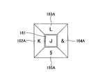
- the GUI buttons 162A to 165A arranged around the GUI button 161 shown in FIG. 14 are trapezoidal.
- the display areas of the GUI buttons 162A to 165A coincide with the areas 162 ⁇ to 165 ⁇ (see FIG. 8) in which the touch panel 150 determines whether or not there is an operation input to the GUI buttons 162 to 165 shown in FIGS.
- Such GUI buttons 162A to 165A may be used.
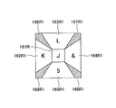
- the regions 162R1 to 165R1 shown in FIG. 15 are expanded compared to the regions 162R to 165R shown in FIG.
- the regions 162R to 165R are each square, whereas the regions 162R1 to 165R1 are trapezoidal on the outside.
- the regions 166R1 to 169R1 are narrower than the regions 166R to 169R shown in FIG.
- regions 161R and 162R1 to 165R1 that generate the natural vibration of the ultrasonic band when the user touches and moves the top panel 120 are outlined, and the user places the fingertip on the top panel 120.
- the regions 166R1 to 169R1 that do not generate the natural vibration of the ultrasonic band when touched and moved are indicated by hatching.
- the display areas of the GUI buttons 161 to 165 are the same as those shown in FIGS.
- the vibration element 140 is driven, and the natural vibration of the ultrasonic band is generated in the top panel 120. . Further, when the fingertip is moved while touching the top panel 120 in the regions 162R to 165R, the vibration element 140 is not driven, and thus the natural vibration of the ultrasonic band is not generated in the top panel 120.
- the regions 162R2 to 165R2 shown in FIG. 16 are slightly narrowed so that regions that do not generate the natural vibration of the ultrasonic band are provided between the regions 162R.
- regions 161R and 162R2 to 165R2 in which the natural vibration of the ultrasonic band is generated when the user touches and moves the top panel 120 are outlined, and the user places the fingertip on the top panel 120.
- a region where the natural vibration of the ultrasonic band is not generated when touched and moved is indicated by hatching.
- the area 162R3 shown in FIG. 17 may be used.
- the region 162R3 is obtained by expanding the region 162R illustrated in FIG.
- the region 166R3 corresponding to the region 166R shown in FIG. 10 is narrowed by the amount of the region 162R3 expanded.
- the area 162R shown in FIG. 10 may be changed to the area 162R3 shown in FIG.
- Such a region 162R3 can be used in the following cases, for example.
- the user can recognize with the tactile sensation that the boundary A has been exceeded, and can recognize with the tactile sensation that the user has erroneously entered “K” while wishing to input “L”.
- the region 163R4 shown in FIG. 19 may be used.
- the region 163R4 is obtained by expanding the region 163R illustrated in FIG.
- the region 166R4 corresponding to the region 166R shown in FIG. 10 is narrowed by the amount of the region 163R4 expanded.
- the region 163R shown in FIG. 10 may be changed to the region 163R4 shown in FIG.
- the drive control unit 240 performs drive control of the vibration element 140 using the regions 161R to 165R and the regions 165R to 169R shown in FIG. 10, the operation input position further reaches the boundaries A to D.
- the vibration element 140 may be driven.
- the top panel 120 is traced with a fingertip from the region 163R shown in FIG. 10 (position “L”) through the region 166R to the region 162R (position “K”).
- the drive control unit 240 causes the natural vibration of the ultrasonic band of amplitude A ⁇ b> 11 to the top panel 120. generate.
- the drive control unit 240 turns off the vibration element 140, so that the amplitude of vibration generated in the top panel 120 becomes zero.
- the drive control unit 240 causes the top panel 120 to generate the natural vibration of the ultrasonic band having the amplitude A11. Thereby, the user can recognize that the boundary A has been reached by the tactile sensation of the fingertip.
- the drive control unit 240 turns off the vibration element 140, and therefore the amplitude of vibration generated in the top panel 120 Becomes zero.
- the drive control unit 240 takes the natural vibration of the ultrasonic band of amplitude A11 to the top. Generated on panel 120. As a result, the user can recognize that the position “K” has been reached by the tactile sensation of the fingertip.
- the vibration element 140 is turned on so that the natural vibration of the ultrasonic band is generated in the top panel 120 so that the position of the boundary A is conveyed to the user by tactile sensation. Good.
- the boundary 166R in the region 166R shown in FIG. A narrow region along A may be allocated as a region for driving the vibration element 140, similarly to the regions 162R to 165R.
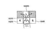
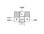
- the right-handed person and left-handed person may have different trajectories for flick operations. For this reason, for example, when the user is right-handed, the region 163R shown in FIG. 10 may be biased to the left as in the region 163R5 shown in FIG.
- the area 163R shown in FIG. 10 may be biased to the right as in the area 163R6 shown in FIG.
- the regions 161R to 165R may be asymmetrical so that right-handed users and left-handed users can use them easily.
- FIG. 23 shows an upward flick as shown by an arrow in order to select “L” from the state where the user's fingertip touches the alphabet “J” at the position C11 in the operation mode for editing the e-mail. Indicates the state of operation.
- FIG. 23 shows GUI buttons 161A to 169A.
Landscapes
- Engineering & Computer Science (AREA)
- General Engineering & Computer Science (AREA)
- Theoretical Computer Science (AREA)
- Human Computer Interaction (AREA)
- Physics & Mathematics (AREA)
- General Physics & Mathematics (AREA)
- User Interface Of Digital Computer (AREA)
Abstract
正確な入力を支援する駆動制御装置を提供する。 表示部の表示面側に配設されるトップパネルの操作面での操作入力の位置を検出する位置検出部と、操作面に振動を発生させる振動素子とを含む電子機器の振動素子を駆動する駆動制御装置であって、表示部に表示される記号の入力部であって、第1記号入力用の第1入力部と、第1入力部の周囲に表示され、互いに異なる複数の第2記号入力用の複数の第2入力部とを有する入力部の画像データと、第1入力部の表示領域に対応する第1領域と、複数の第2入力部の表示領域に対応する複数の第2領域との位置を表す領域データとを格納する格納部と、操作面に超音波帯の固有振動を発生させる駆動信号で振動素子を駆動する駆動制御部であって、操作入力の位置が第1領域及び複数の第2領域の外部に移動すると、又は、第2領域同士の境界に達すると、固有振動の強度が変化するように振動素子を駆動する駆動制御部を含む。
Description
本発明は、駆動制御装置、電子機器、駆動制御プログラム、及び駆動制御方法に関する。
従来より、タッチパネルと、入力座標を検出する検出部と、上記入力座標の文字を選択文字とし、この選択文字とこの選択文字と特定の関係にある候補文字とで成る入力ガイドを表示する入力ガイド表示部と、タッチダウン操作かタッチアップ操作かフリック操作かを判定する操作判定部とを備える文字入力装置がある。上記タッチダウン操作の場合は、上記入力ガイドの選択文字のガイドボタンの領域を確定領域とし、上記フリック操作の場合には、スライド後の箇所で指定される候補文字のガイドボタンの領域を確定領域とし、上記タッチアップ操作の場合には、上記確定領域の文字を入力文字として確定する文字入力制御部をさらに備える。文字入力制御部は、上記フリック操作の場合は上記確定領域を拡大する(例えば、特許文献1参照)。
従来の文字入力装置では、利用者は、入力座標が選択文字の入力領域から候補文字の入力領域に移動する際に、2つの入力領域の境界を視覚で認識し、選択文字又は候補文字のどちらかを選択する。
しかしながら、2つの入力領域の境界を視覚で認識するのは困難であり、入力ミスが生じるおそれがある。また、このような問題は、文字を入力する場合に限られず、数字又は様々な記号を入力する場合においても同様に生じる。
そこで、正確な入力を支援する駆動制御装置、電子機器、駆動制御プログラム、及び駆動制御方法を提供することを目的とする。
本発明の実施の形態の駆動制御装置は、表示部と、前記表示部の表示面側に配設され、操作面を有するトップパネルと、前記操作面に行われる操作入力の位置を検出する位置検出部と、前記操作面に振動を発生させる振動素子とを含む電子機器の前記振動素子を駆動する駆動制御装置であって、前記表示部に表示され、記号の入力に用いられる記号入力部であって、第1記号の入力に用いられる第1入力部と、前記第1入力部の周囲に表示され、互いに異なる複数の第2記号の入力に用いられる複数の第2入力部とを有する記号入力部の画像を表す画像データと、前記第1入力部の表示領域に対応する第1領域と、前記複数の第2入力部の表示領域に対応する複数の第2領域との位置を表す領域データとを格納する格納部と、前記操作面に超音波帯の固有振動を発生させる駆動信号で前記振動素子を駆動する駆動制御部であって、前記操作入力の位置が前記第1領域及び前記複数の第2領域の外部に移動すると、又は、前記第2領域同士の境界に達すると、前記固有振動の強度が変化するように第1振動パターンで前記振動素子を駆動する駆動制御部とを含み、前記第1領域は、前記第1入力部の第1表示領域と等しい、又は、前記第1表示領域を含み、前記第1表示領域よりも大きい領域であり、前記複数の第2領域は、それぞれ、前記複数の第2入力部の複数の第2表示領域と等しい、又は、前記複数の第2表示領域を含み、前記複数の第2表示領域よりも大きい領域である。
正確な入力を支援する駆動制御装置、電子機器、駆動制御プログラム、及び駆動制御方法を提供することができる。
以下、本発明の駆動制御装置、電子機器、駆動制御プログラム、及び駆動制御方法を適用した実施の形態について説明する。
<実施の形態>
図1は、実施の形態の電子機器100を示す斜視図である。
図1は、実施の形態の電子機器100を示す斜視図である。
電子機器100は、一例として、タッチパネルを入力操作部とする、スマートフォン端末機、又は、タブレット型コンピュータである。電子機器100は、タッチパネルを入力操作部とする機器であればよいため、例えば、携帯情報端末機、又は、ATM(Automatic Teller Machine)のように特定の場所に設置されて利用される機器であってもよい。
電子機器100の入力操作部101は、タッチパネルの下にディスプレイパネルが配設されており、ディスプレイパネルにGUI(Graphic User Interface)による様々なボタン102A、又は、スライダー102B等(以下、GUI操作部102と称す)が表示される。
電子機器100の利用者は、通常、GUI操作部102を操作するために、指先で入力操作部101に触れる。
次に、図2を用いて、電子機器100の具体的な構成について説明する。
図2は、実施の形態の電子機器100を示す平面図であり、図3は、図2に示す電子機器100のA-A矢視断面を示す図である。なお、図2及び図3では、図示するように直交座標系であるXYZ座標系を定義する。
電子機器100は、筐体110、トップパネル120、両面テープ130、振動素子140、タッチパネル150、ディスプレイパネル160、及び基板170を含む。
筐体110は、例えば、樹脂製であり、図3に示すように凹部110Aに基板170、ディスプレイパネル160、及びタッチパネル150が配設されるとともに、両面テープ130によってトップパネル120が接着されている。
トップパネル120は、平面視で長方形の薄い平板状の部材であり、透明なガラス、又は、ポリカーボネートのような強化プラスティックで作製される。トップパネル120の表面(Z軸正方向側の面)は、電子機器100の利用者が操作入力を行う操作面の一例である。
トップパネル120は、Z軸負方向側の面に振動素子140が接着され、平面視における四辺が両面テープ130によって筐体110に接着されている。なお、両面テープ130は、トップパネル120の四辺を筐体110に接着できればよく、図3に示すように矩形環状である必要はない。
トップパネル120のZ軸負方向側にはタッチパネル150が配設される。トップパネル120は、タッチパネル150の表面を保護するために設けられている。なお、トップパネル120の表面に、さらに別なパネル又は保護膜等が設けられていてもよい。
トップパネル120は、Z軸負方向側の面に振動素子140が接着された状態で、振動素子140が駆動されることによって振動する。実施の形態では、トップパネル120の固有振動周波数でトップパネル120を振動させて、トップパネル120に定在波を生じさせる。ただし、トップパネル120には振動素子140が接着されているため、実際には、振動素子140の重さ等を考慮した上で、固有振動周波数を決めることが好ましい。
振動素子140は、トップパネル120のZ軸負方向側の面において、Y軸正方向側において、X軸方向に伸延する短辺に沿って接着されている。振動素子140は、超音波帯の振動を発生できる素子であればよく、例えば、ピエゾ素子のような圧電素子を含むものを用いることができる。
振動素子140は、後述する駆動制御部から出力される駆動信号によって駆動される。振動素子140が発生する振動の振幅(強度)及び周波数は駆動信号によって設定される。また、振動素子140のオン/オフは駆動信号によって制御される。
なお、超音波帯とは、例えば、約20kHz以上の周波数帯をいう。実施の形態の電子機器100では、振動素子140が振動する周波数は、トップパネル120の振動数と等しくなるため、振動素子140は、トップパネル120の固有振動数で振動するように駆動信号によって駆動される。
タッチパネル150は、ディスプレイパネル160の上(Z軸正方向側)で、トップパネル120の下(Z軸負方向側)に配設されている。タッチパネル150は、電子機器100の利用者がトップパネル120に触れる位置(以下、操作入力の位置と称す)を検出する位置検出部の一例である。
タッチパネル150の下にあるディスプレイパネル160には、GUIによる様々なボタン等(以下、GUI操作部と称す)が表示される。このため、電子機器100の利用者は、通常、GUI操作部を操作するために、指先でトップパネル120に触れる。
タッチパネル150は、利用者のトップパネル120への操作入力の位置を検出できる位置検出部であればよく、例えば、静電容量型又は抵抗膜型の位置検出部であればよい。ここでは、タッチパネル150が静電容量型の位置検出部である形態について説明する。タッチパネル150とトップパネル120との間に隙間があっても、静電容量型のタッチパネル150は、トップパネル120への操作入力を検出できる。
また、ここでは、タッチパネル150の入力面側にトップパネル120が配設される形態について説明するが、トップパネル120はタッチパネル150と一体的であってもよい。この場合、タッチパネル150の表面が図2及び図3に示すトップパネル120の表面になり、操作面を構築する。また、図2及び図3に示すトップパネル120を省いた構成であってもよい。この場合も、タッチパネル150の表面が操作面を構築する。また、この場合には、操作面を有する部材を、当該部材の固有振動で振動させればよい。
また、タッチパネル150が静電容量型の場合は、トップパネル120の上にタッチパネル150が配設されていてもよい。この場合も、タッチパネル150の表面が操作面を構築する。また、タッチパネル150が静電容量型の場合は、図2及び図3に示すトップパネル120を省いた構成であってもよい。この場合も、タッチパネル150の表面が操作面を構築する。また、この場合には、操作面を有する部材を、当該部材の固有振動で振動させればよい。
ディスプレイパネル160は、例えば、液晶ディスプレイパネル又は有機EL(Electroluminescence)パネル等の画像を表示できる表示部であればよい。ディスプレイパネル160は、筐体110の凹部110Aの内部で、図示を省略するホルダ等によって基板170の上(Z軸正方向側)に設置される。
ディスプレイパネル160は、後述するドライバIC(Integrated Circuit)によって駆動制御が行われ、電子機器100の動作状況に応じて、GUI操作部、画像、文字、記号、図形等を表示する。
基板170は、筐体110の凹部110Aの内部に配設される。基板170の上には、ディスプレイパネル160及びタッチパネル150が配設される。ディスプレイパネル160及びタッチパネル150は、図示を省略するホルダ等によって基板170及び筐体110に固定されている。
基板170には、後述する駆動制御装置の他に、電子機器100の駆動に必要な種々の回路等が実装される。
以上のような構成の電子機器100は、トップパネル120に利用者の指が接触し、指先の移動を検出すると、基板170に実装される駆動制御部が振動素子140を駆動し、トップパネル120を超音波帯の周波数で振動させる。この超音波帯の周波数は、トップパネル120と振動素子140とを含む共振系の共振周波数であり、トップパネル120に定在波を発生させる。
電子機器100は、超音波帯の定在波を発生させることにより、トップパネル120を通じて利用者に触感を提供する。
次に、図4を用いて、トップパネル120に発生させる定在波について説明する。
図4は、超音波帯の固有振動によってトップパネル120に生じる定在波のうち、トップパネル120の短辺に平行に形成される波頭を示す図であり、図4の(A)は側面図、(B)は斜視図である。図4の(A)、(B)では、図2及び図3と同様のXYZ座標を定義する。なお、図4の(A)、(B)では、理解しやすさのために、定在波の振幅を誇張して示す。また、図4の(A)、(B)では振動素子140を省略する。
トップパネル120のヤング率E、密度ρ、ポアソン比δ、長辺寸法l、厚さtと、長辺方向に存在する定在波の周期数kとを用いると、トップパネル120の固有振動数(共振周波数)fは次式(1)、(2)で表される。定在波は1/2周期単位で同じ波形を有するため、周期数kは、0.5刻みの値を取り、0.5、1、1.5、2・・・となる。

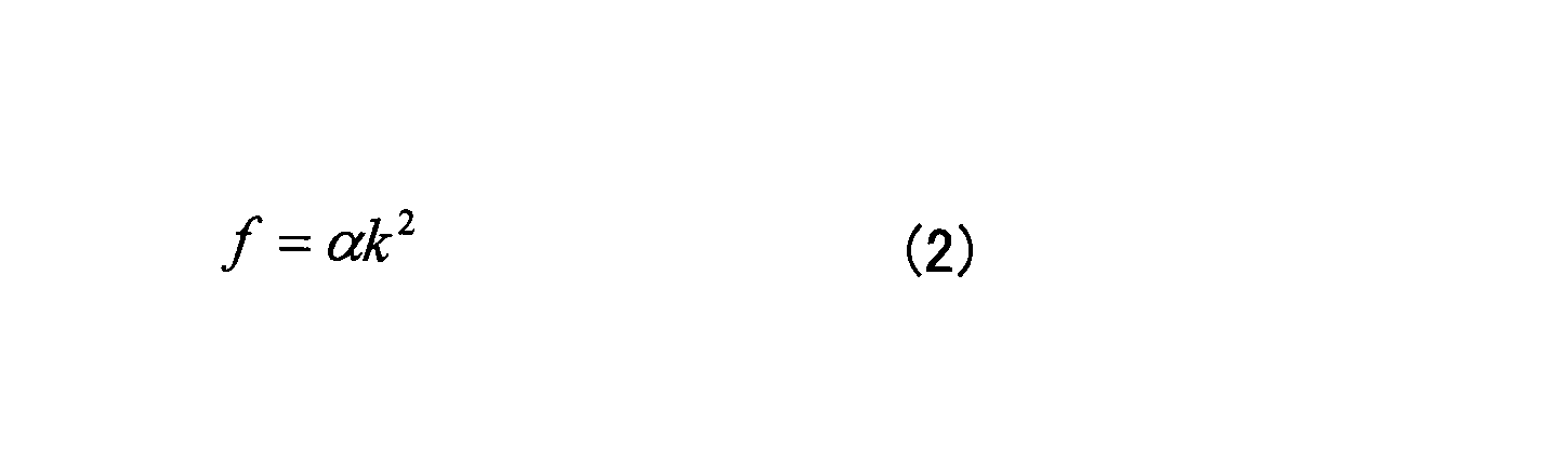
図4の(A)、(B)に示す定在波は、一例として、周期数kが10の場合の波形である。例えば、トップパネル120として、長辺の長さlが140mm、短辺の長さが80mm、厚さtが0.7mmのGorilla(登録商標)ガラスを用いる場合には、周期数kが10の場合に、固有振動数fは33.5[kHz]となる。この場合は、周波数が33.5[kHz]の駆動信号を用いればよい。
トップパネル120は、平板状の部材であるが、振動素子140(図2及び図3参照)を駆動して超音波帯の固有振動を発生させると、図4の(A)、(B)に示すように撓むことにより、表面に定在波が生じる。
なお、ここでは、1つの振動素子140がトップパネル120のZ軸負方向側の面において、Y軸正方向側において、X軸方向に伸延する短辺に沿って接着される形態について説明するが、振動素子140を2つ用いてもよい。2つの振動素子140を用いる場合は、もう1つの振動素子140をトップパネル120のZ軸負方向側の面において、Y軸負方向側において、X軸方向に伸延する短辺に沿って接着すればよい。この場合に、2つの振動素子140は、トップパネル120の2つの短辺に平行な中心線を対称軸として、軸対称になるように配設すればよい。
また、2つの振動素子140を駆動する場合は、周期数kが整数の場合は同一位相で駆動すればよく、周期数kが小数(整数部と小数部とを含む数)の場合は逆位相で駆動すればよい。
次に、図5を用いて、電子機器100のトップパネル120に生じさせる超音波帯の固有振動について説明する。
図5は、電子機器100のトップパネル120に生じさせる超音波帯の固有振動により、操作入力を行う指先に掛かる動摩擦力が変化する様子を説明する図である。図5の(A)、(B)では、利用者が指先でトップパネル120に触れながら、指をトップパネル120の奥側から手前側に矢印に沿って移動する操作入力を行っている。なお、振動のオン/オフは、振動素子140(図2及び図3参照)をオン/オフすることによって行われる。
また、図5の(A)、(B)では、トップパネル120の奥行き方向において、振動がオフの間に指が触れる範囲をグレーで示し、振動がオンの間に指が触れる範囲を白く示す。
超音波帯の固有振動は、図4に示すようにトップパネル120の全体に生じるが、図5の(A)、(B)には、利用者の指がトップパネル120の奥側から手前側に移動する間に振動のオン/オフを切り替える動作パターンを示す。
このため、図5の(A)、(B)では、トップパネル120の奥行き方向において、振動がオフの間に指が触れる範囲をグレーで示し、振動がオンの間に指が触れる範囲を白く示す。
図5の(A)に示す動作パターンでは、利用者の指がトップパネル120の奥側にあるときに振動がオフであり、指を手前側に移動させる途中で振動がオンになっている。
一方、図5の(B)に示す動作パターンでは、利用者の指がトップパネル120の奥側にあるときに振動がオンであり、指を手前側に移動させる途中で振動がオフになっている。
ここで、トップパネル120に超音波帯の固有振動を生じさせると、トップパネル120の表面と指との間にスクイーズ効果による空気層が介在し、指でトップパネル120の表面をなぞったときの動摩擦係数が低下する。
従って、図5の(A)では、トップパネル120の奥側にグレーで示す範囲では、指先に掛かる動摩擦力は大きく、トップパネル120の手前側に白く示す範囲では、指先に掛かる動摩擦力は小さくなる。
このため、図5の(A)に示すようにトップパネル120に操作入力を行う利用者は、振動がオンになると、指先に掛かる動摩擦力の低下を感知し、指先の滑り易さを知覚することになる。このとき、利用者はトップパネル120の表面がより滑らかになることにより、動摩擦力が低下するときに、トップパネル120の表面に凹部が存在するように感じる。
一方、図5の(B)では、トップパネル120の奥前側に白く示す範囲では、指先に掛かる動摩擦力は小さく、トップパネル120の手前側にグレーで示す範囲では、指先に掛かる動摩擦力は大きくなる。
このため、図5の(B)に示すようにトップパネル120に操作入力を行う利用者は、振動がオフになると、指先に掛かる動摩擦力の増大を感知し、指先の滑り難さ、あるいは、引っ掛かる感じを知覚することになる。そして、指先が滑りにくくなることにより、動摩擦力が高くなるときに、トップパネル120の表面に凸部が存在するように感じる。
以上より、図5の(A)と(B)の場合は、利用者は指先で凹凸を感じ取ることができる。このように人間が凹凸の知覚することは、例えば、"触感デザインのための印刷物転写法とSticky-band Illusion"(第11回計測自動制御学会システムインテグレーション部門講演会論文集 (SI2010, 仙台)____174-177, 2010-12)に記載されている。また、"Fishbone Tactile Illusion"(日本バーチャルリアリティ学会第10 回大会論文集(2005 年9 月))にも記載されている。
なお、ここでは、振動のオン/オフを切り替える場合の動摩擦力の変化について説明したが、これは、振動素子140の振幅(強度)を変化させた場合も同様である。
次に、図6を用いて、実施の形態の電子機器100の構成について説明する。
図6は、実施の形態の電子機器100の構成を示す図である。
電子機器100は、振動素子140、アンプ141、タッチパネル150、ドライバIC(Integrated Circuit)151、ディスプレイパネル160、ドライバIC160A、制御部200、正弦波発生器310、及び振幅変調器320を含む。
制御部200は、アプリケーションプロセッサ220、通信プロセッサ230、駆動制御部240、及びメモリ250を有する。制御部200は、例えば、ICチップで実現される。
また、駆動制御部240、正弦波発生器310、及び振幅変調器320は、駆動制御装置300を構築する。なお、ここでは、アプリケーションプロセッサ220、通信プロセッサ230、駆動制御部240、及びメモリ250が1つの制御部200によって実現される形態について説明するが、駆動制御部240は、制御部200の外部に別のICチップ又はプロセッサとして設けられていてもよい。この場合には、メモリ250に格納されているデータのうち、駆動制御部240の駆動制御に必要なデータは、メモリ250とは別のメモリに格納して、駆動制御装置300の内部に設ければよい。
図6では、筐体110、トップパネル120、両面テープ130、及び基板170(図2参照)は省略する。また、ここでは、アンプ141、ドライバIC151、ドライバIC160A、駆動制御部240、メモリ250、正弦波発生器310、及び振幅変調器320について説明する。
アンプ141は、駆動制御装置300と振動素子140との間に配設されており、駆動制御装置300から出力される駆動信号を増幅して振動素子140を駆動する。
ドライバIC151は、タッチパネル150に接続されており、タッチパネル150への操作入力があった位置を表す位置データを検出し、位置データを制御部200に出力する。この結果、位置データは、アプリケーションプロセッサ220と駆動制御部240に入力される。なお、位置データが駆動制御部240に入力されることは、位置データが駆動制御装置300に入力されることと等価である。
ドライバIC160Aは、ディスプレイパネル160に接続されており、駆動制御装置300から出力される描画データをディスプレイパネル160に入力し、描画データに基づく画像をディスプレイパネル160に表示させる。これにより、ディスプレイパネル160には、描画データに基づくGUI操作部又は画像等が表示される。
アプリケーションプロセッサ220は、電子機器100の種々のアプリケーションを実行する処理を行う。
通信プロセッサ230は、電子機器100が3G(Generation)、4G(Generation)、LTE(Long Term Evolution)、WiFi等の通信を行うために必要な処理を実行する。
駆動制御部240は、所定の条件が揃った場合に、振幅データを振幅変調器320に出力する。振幅データは、振動素子140の駆動に用いる駆動信号の強度を調整するための振幅値を表すデータである。振幅値は、位置データの時間的変化度合に応じて設定される。
ここで、位置データの時間的変化度合としては、利用者の指先がトップパネル120の表面に沿って移動する速度を用いる。利用者の指先の移動速度は、ドライバIC151から入力される位置データの時間的な変化度合に基づいて、駆動制御部240が算出する。
なお、振幅データによってトップパネル120に生じる超音波帯の固有振動の振幅の変動の周波数は、人間が指先の触感で感じ取ることができるように、約1kHz以下の周波数に設定される。
また、実施の形態の駆動制御装置300は、利用者の指先がトップパネル120の表面に沿って移動したときに、指先に掛かる動摩擦力を変化させるためにトップパネル120を振動させる。動摩擦力は、指先が移動しているときに発生するため、駆動制御部240は、移動速度が所定の閾値速度以上になったときに、振動素子140を振動させる。 また、実施の形態の駆動制御装置300は、操作入力を行う指先の位置が、振動を発生させるべき所定の領域内にある場合に、振幅データを振幅変調器320に出力する。
操作入力を行う指先の位置が振動を発生させるべき所定の領域内にあるかどうかは、操作入力を行う指先の位置が、振動を発生させるべき所定の領域の内部にあるか否かに基づいて判定される。
ここで、ディスプレイパネル160に表示するGUI操作部、画像を表示する領域、又は、ページ全体を表す領域等のディスプレイパネル160上における位置は、当該領域を表す領域データによって特定される。領域データは、すべてのアプリケーションにおいて、ディスプレイパネル160に表示されるすべてのGUI操作部、画像を表示する領域、又は、ページ全体を表す領域について存在する。
トップパネル120の表面に触れた指先を移動させる操作入力の種類としては、例えば、GUI操作部を操作する際には、所謂フリック操作がある。フリック操作は、指先をトップパネル120の表面に沿って、はじく(スナップする)ように比較的短い距離移動させる操作である。
また、ページを捲る場合には、例えば、スワイプ操作を行う。スワイプ操作は、指先をトップパネル120の表面に沿って掃くように比較的長い距離移動させる操作である。スワイプ操作は、ページを捲る場合の他に、例えば、写真を捲る場合に行われる。また、GUI操作部によるスライダー(図1のスライダー102B参照)をスライドさせる場合には、スライダーをドラッグするドラッグ操作が行われる。
ここで一例として挙げるフリック操作、スワイプ操作、及びドラッグ操作のように、トップパネル120の表面に触れた指先を移動させる操作入力は、アプリケーションによる表示の種類によって使い分けられる。このため、操作入力を行う指先の位置が、振動を発生させるべき所定の領域内にあるかどうかを判定する際には、電子機器100が起動しているアプリケーションの種類が関係することになる。
駆動制御部240は、領域データを用いて、ドライバIC151から入力される位置データが表す位置が、振動を発生させるべき所定の領域の内部にあるか否かを判定する。
アプリケーションの種類を表すデータと、操作入力が行われるGUI操作部等を表す領域データと、振動パターンを表すパターンデータとを関連付けたデータは、メモリ250に格納されている。
また、駆動制御部240は、ドライバIC151から駆動制御装置300に位置データが入力されてから、当該位置データに基づいて駆動信号が算出されるまでの所要時間の間における指先の位置の変化分を補間するために、次の処理を行う。
駆動制御装置300は、所定の制御周期毎に演算を行う。これは駆動制御部240も同様である。このため、ドライバIC151から駆動制御装置300に位置データが入力されてから、当該位置データに基づいて駆動制御部240が駆動信号を算出するまでの所要時間をΔtとすると、所要時間Δtは、制御周期に等しい。
ここで、指先の移動速度は、ドライバIC151から駆動制御装置300に入力される位置データが表す点(x1、y1)を始点とし、所要時間Δtが経過した後の指先の位置を終点(x2、y2)とするベクトルの速度として求めることができる。
メモリ250は、アプリケーションの種類を表すデータと、GUIボタンの画像データと、第1領域データと、第2領域データと、振動パターンとを関連付けたデータを格納する。
また、メモリ250は、アプリケーションプロセッサ220がアプリケーションの実行に必要とするデータ及びプログラム、及び、通信プロセッサ230が通信処理に必要とするデータ及びプログラム等を格納する。
正弦波発生器310は、トップパネル120を固有振動数で振動させるための駆動信号を生成するのに必要な正弦波を発生させる。例えば、トップパネル120を33.5[kHz]の固有振動数fで振動させる場合は、正弦波の周波数は、33.5[kHz]となる。正弦波発生器310は、超音波帯の正弦波信号を振幅変調器320に入力する。
振幅変調器320は、駆動制御部240から入力される振幅データを用いて、正弦波発生器310から入力される正弦波信号の振幅を変調して駆動信号を生成する。振幅変調器320は、正弦波発生器310から入力される超音波帯の正弦波信号の振幅のみを変調し、周波数及び位相は変調せずに、駆動信号を生成する。
このため、振幅変調器320が出力する駆動信号は、正弦波発生器310から入力される超音波帯の正弦波信号の振幅のみを変調した超音波帯の正弦波信号である。なお、振幅データがゼロの場合は、駆動信号の振幅はゼロになる。これは、振幅変調器320が駆動信号を出力しないことと等しい。
ここで、図7乃至図9を用いて、入力操作における問題点について説明する。
図7は、電子機器100のメールの入力画面を示す図である。図9は、図7に示す入力部の一部を拡大して示す図である。なお、ここでは、比較用に振動素子140を駆動しない場合について説明し、振動素子140を駆動することによる作用及び効果について後述する。
図7では、電子メールを編集する動作モードにおいて、"J","K","L","5"、又は"&"を選択するGUIボタンに利用者の指先が触れて、"J"を選択するGUIボタン161の四方に、"K","L","5"、又は"&"を選択するGUIボタン162、163、164、165が表示されている。GUIボタン161は、第1入力部の一例である。GUIボタン162、163、164、165の各々は、第2入力部の一例である。
GUIボタン161に操作入力を行っていないときは、GUIボタン161は、"J","K","L","5"、及び"&"を表示する。これは、"P"、"Q"、"R"、"S"、又は"7"を入力するGUIボタン169Aと同様である。
例えば、GUIボタン161に指先を触れた状態から、GUIボタン163の方向にフリック操作を行うと、"L"を入力することができる。
ここでは、このようなGUIボタンを展開式のGUIボタンと称す。展開式のGUIボタンとは、操作入力を行うと(指先で触れると)、GUIボタンが展開して、触れているGUIボタンの周囲に、その他のGUIボタンが配置されるGUIボタンをいう。
このような展開式のGUIボタンは、一例として、記号の入力を行う際に用いられる。記号とは、文字、数字、絵文字、顔文字、その他の記号を含む総称である。また、文字は、平仮名、カタカナ、漢字、アルファベット、及びその他の言語の表記に用いる文字である。
図8は、GUIボタン162~165への入力が受け付けられる領域を示す図である。
図8では、GUIボタン161の表示領域内でトップパネル120に指先で触れた(操作入力を行った)状態から、指先をGUIボタン161の外側に移動させた場合に、GUIボタン162~165が展開されている状態を示す。
領域162α、163α、164α、165αは、それぞれ、GUIボタン162~165への操作入力が受け付けられる(認識される)範囲を表す。領域162α、163α、164α、165αは、GUIボタン161の周囲の四方に均等に広がるように規定される台形型の領域である。
領域162α~165αに指先が位置しているときに、指先をトップパネル120から離すと、それぞれ、GUIボタン162~165への入力が完了する。
なお、GUIボタン161への入力が受け付けられる領域は、GUIボタン161の表示領域と略等しく、領域162α~165αとは重複せずに、領域162α~165αに囲まれた領域である。
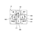
次に、図9を用いて、GUIボタン161に指先を触れた状態から、"L"を入力するためにGUIボタン163の方向に指先を移動させてから、さらにGUIボタン162の方向に指先を移動させる場合について考える。
図9に示す軌跡(1)及び(2)は、指先の軌跡を示す。軌跡(1)及び(2)のうち、実線の区間は、指先がトップパネル120に触れながら移動する区間を示し、破線の区間は、トップパネル120に指先を触れずに移動する区間を示す。軌跡(1)及び(2)は、GUIボタン161を操作して"L"を入力してから、"P"、"Q"、"R"、"S"、又は"7"を入力するGUIボタン169Aを操作するために指先を移動させる軌跡を表す。
また、一点鎖線で示す境界Aは、タッチパネル150がGUIボタン162への入力を検出する領域と、GUIボタン163への入力を検出する領域との境界を示す。すなわち、境界Aは、図8に示す領域162αと163αとの境界である。
境界AよりもGUIボタン162側の領域でトップパネル120に触れると、"K"の入力操作が行われたことになる。境界AよりもGUIボタン163側の領域でトップパネル120に触れると、"L"の入力操作が行われたことになる。
軌跡(1)は、GUIボタン161に指先を触れた状態から、GUIボタン163の方向に指先を移動させてから、GUIボタン162の方向に指先を移動させるときに、境界Aよりも手前で(GUIボタン162側で)指先をトップパネル120から離していることを示す。軌跡(1)のように操作入力を行うと、"L"を入力することができる。
また、軌跡(2)は、GUIボタン161に指先を触れた状態から、GUIボタン163の方向に指先を移動させてから、GUIボタン162の方向に指先を移動させるときに、境界Aを越えてから指先をトップパネル120から離していることを示す。
すなわち、軌跡(2)のように操作入力を行うと、"L"を入力することができず、誤って"K"が入力されることになる。
フリック操作を素早く行うと、指先をトップパネル120から離す位置がずれる可能性があるため、軌跡(1)のように操作するつもりでも、軌跡(2)のように境界Aを越えてから指先をトップパネル120から離してしまい、"L"を入力することができず、誤って"K"が入力されてしまうことが起こり得る。
このような入力ミスは、指先を素早く動かして操作入力を行う場合、又は、片手で電子機器100を持ちながら操作入力を行うような場合に、特に生じやすい。
以下では、このような場合に、振動素子140を駆動してトップパネル120に超音波帯の固有振動を生じさせることにより、入力ミスを低減する形態について説明する。
図10は、振動を発生させる領域と、振動を発生させない領域と、及びGUIボタン162~165の入力領域の境界との位置関係を示す図である。
図10には、領域161R、162R、163R、164R、165Rと、領域166R、167R、168R、169Rと、境界A、B、C、Dとを示す。領域161R~169Rは、3行×3列のマトリクス状に配列される9つの領域である。
領域161R~165Rは、これらの領域の中で操作入力の位置が移動すると、駆動制御部240が振動素子140を駆動してトップパネル120に超音波帯の固有振動を発生させる領域である。領域161Rは、第1領域の一例である。領域162R~165Rの各々は、第2領域の一例である。
領域166R~169Rは、これらの領域の中で操作入力の位置が移動しても、駆動制御部240が振動素子140を駆動しない領域である。
領域161R~165Rの座標は、タッチパネル150の座標系における座標で表される。領域161R~165Rの位置は、ディスプレイパネル160にGUIボタン161~165(図7及び図9参照)が表示される位置と平面視で一致している。
また、領域166R~169Rは、3行×3列のマトリクス状に配列される9つの領域から領域161R~165Rを除いた4つの領域である。領域166R~169Rの座標は、タッチパネル150の座標系における座標で表される。
ここで、領域166Rは、領域162Rと領域163Rとの境界として捉えることができる。例えば、図9に示す軌跡(1)のように、操作入力の位置が領域163Rから領域166Rを経て領域163Rに移動する場合には、領域166Rは、領域162Rと領域163Rとの境界になる。これは、領域167R~169Rについても同様である。
境界Aは、図9に示す境界Aと同一であり、タッチパネル150がGUIボタン162への入力を検出する領域162αと、GUIボタン163への入力を検出する領域163αとの境界を示す。
境界Bは、タッチパネル150がGUIボタン163への入力を検出する領域163αと、GUIボタン164への入力を検出する領域164αとの境界を示す。
境界Cは、タッチパネル150がGUIボタン164への入力を検出する領域164αと、GUIボタン165への入力を検出する領域165αとの境界を示す。
境界Dは、タッチパネル150がGUIボタン165への入力を検出する領域165αと、GUIボタン162への入力を検出する領域162αとの境界を示す。
駆動制御部240は、操作入力の位置が領域161R~165Rのうちのいずれかの中にあって、かつ、操作入力の位置が移動しているときに、振動素子140を駆動して、トップパネル120に超音波帯の固有振動を発生させる。
また、駆動制御部240は、操作入力の位置が領域166R~169Rのうちのいずれかの中にあるときには、操作入力の位置が移動しても振動素子140を駆動しない。このため、トップパネル120に超音波帯の固有振動は発生しない。
上述のように、トップパネル120に超音波帯の固有振動を発生しているときは、スクイーズ効果によって利用者の指先にかかる摩擦力が低下する。また、トップパネル120に超音波帯の固有振動を発生していないときは、スクイーズ効果が得られないため、利用者の指先にかかる摩擦力が増大する。
すなわち、操作入力の位置が領域161R~165Rのうちのいずれかの中にあるときと、領域166R~169Rのうちのいずれかの中にあるときとでは、利用者が指先を移動させたときに感じる触感が異なる。
従って、利用者は、指先を移動させたときに、指先の位置が領域161R~165Rのうちのいずれかの中にあるかどうかを指先の触感で判断することができる。
なお、ここでは、領域166R~169Rの大きさが領域161R~165Rと等しいように示すが、領域166R~169Rは、さらに外側に拡がっていてもよい。
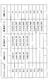
図11は、アプリケーションID(Identification)と、画像データと、第1領域データと、第2領域データと、振動パターンとを関連付けたデータを示す図である。
アプリケーションIDは、アプリケーションの種類を表すデータであり、図11にはID_3を示す。画像データは、ディスプレイパネル160に表示されるGUI部品の画像データと、画像が表示される位置とを表すデータである。ここでは、一例として、GUIボタン161~165(図7及び図9参照)の画像と、画像を表示する位置とを表すデータimage-161~image_165を示す。
第1領域データは、GUI部品への入力を受け付ける領域を表すデータであり、例えば、GUIボタン161~165への入力を受け付ける領域を表すデータである。GUIボタン161~165への入力を受け付ける領域は、それぞれ、input_area_161~input_area_165で表される。input_area_161は、GUIボタン161が表示される領域の座標を表す。input_area_162~input_area_165は、それぞれ、図8に示す領域162α~165αの座標を表す。
第2領域データは、振動の有無を設定する領域を表すデータである。図11では、第2領域データの一例として、vib_area_161R~vib_area_169Rを示す。vib_area_161R~vib_area_169Rは、図10に示す領域161R~169Rの座標を示す。
振動パターンは、各領域データでの超音波帯の固有振動のパターンを示す。領域161R~165RについてはP1の振動パターンが割り当てられている。振動パターンP1は、例えば、ある一定の振幅の超音波帯の固有振動をトップパネル120に生じさせる振動パターンである。
また、領域161R~169Rについては、振動をオフにする振動パターンが割り当てられている。振動をオフにする振動パターンとは、超音波帯の固有振動の振幅をゼロにする振動パターンである。
図12は、実施の形態の電子機器100の駆動制御部240が実行する処理を示すフローチャートである。
電子機器100のOS(Operating System)は、所定の制御周期毎に電子機器100を駆動するための制御を実行する。このため、駆動制御部240は、所定の制御周期毎に演算を行い、図11に示すフローを所定の制御周期毎に繰り返し実行する。
駆動制御部240は、電子機器100の電源が投入されると処理を開始する(スタート)。
駆動制御部240は、展開式のGUIボタンの操作あったかどうかを判定する(ステップS1)。ステップS1の処理は、展開式のGUIボタンの操作あった(S1:YES)と判定されるまで繰り返し実行される。
駆動制御部240は、展開式のGUIボタンの操作あった(S1:YES)と判定すると、操作入力が継続しているかどうかを判定する(ステップS2)。操作入力が継続しているかどうかは、ドライバIC151(図6参照)から位置データが入力されたか否かに基づいて操作入力の有無を判定すればよい。
駆動制御部240は、操作入力が継続していると判定する(S2:YES)と判定すると、操作入力の座標が領域166R~169Rのいずれかに含まれるかどうかを判定する(ステップS3)。ステップS3では、振動素子140を駆動しない領域166R~169Rであるかどうかを判定する。
駆動制御部240は、操作入力の座標が領域166R~169Rに含まれない(S3:NO)と判定すると、振動素子140を駆動しているかどうかを判定する(ステップS4)。
駆動制御部240は、振動素子140を駆動していない(S4:NO)と判定すると、振動素子140の駆動を開始する(ステップS5)。この結果、トップパネル120には、所定の振動パターンによる超音波帯の固有振動が生じる。例えば、操作入力の位置がGUIボタン161(図7及び図9参照)の中にある場合は、図11に示すデータに基づいて、振動パターンP1で振動素子140が駆動される。
振動パターンP1は、所定の一定の振幅で振動素子140を駆動する振動パターンであるため、利用者の指先にはスクイーズ効果によって滑りやすくなる触感が提供される。
駆動制御部240は、ステップS5の処理を終えると、フローをステップS2にリターンする。
また、駆動制御部240は、ステップS4で振動素子140を駆動している(S4:YES)と判定した場合にも、フローをステップS2にリターンする。
駆動制御部240は、ステップS3において、操作入力の座標が領域166R~169Rに含まれる(S3:YES)と判定すると、振動素子140を駆動しているかどうかを判定する(ステップS6)。
駆動制御部240は、振動素子140を駆動している(S6:YES)と判定すると、振動素子140の駆動を停止する(ステップS7)。この結果、トップパネル120に超音波帯の固有振動が生じた状態から、振動がオフにされる。
操作入力の座標は領域166R~169Rに含まれる場合には、振動素子140を駆動せずに、超音波帯の固有振動をオフにするためである。
例えば、操作入力の位置がGUIボタン161~165(図7及び図9参照)のいずれの中にもない場合には、振動素子140は駆動されず、利用者の指先にかかる摩擦力が増大する。これにより、利用者は、指先がGUIボタン161~165から外れたことを触感だけで認識することができる。
駆動制御部240は、ステップS7の処理を終えると、フローをステップS2にリターンする。
また、駆動制御部240は、振動素子140を駆動していない(S6:NO)と判定すると、フローをステップS2にリターンする。
駆動制御部240は、ステップS2において、操作入力が継続していない(S2:NO)と判定すると、振動素子140を駆動しているかどうかを判定する(ステップS8)。
駆動制御部240は、振動素子140を駆動している(S8:YES)と判定すると、振動素子140の駆動を停止する(ステップS9)。この結果、トップパネル120に超音波帯の固有振動が生じた状態から、振動がオフにされる。
操作入力が継続的に行われていない場合には、振動素子140を駆動せずに、超音波帯の固有振動をオフにするためである。
駆動制御部240は、ステップS9の処理を終えると、一連の処理を終了する(エンド)。
また、駆動制御部240は、振動素子140を駆動していない(S8:NO)と判定した場合にも、一連の処理を終了する(エンド)。
ステップS8又はS9を経由してフローが終了する場合は、操作入力による入力内容が確定したか、又は、利用者が入力を途中でキャンセルした場合である。このような場合には、フローが終了する。
ここで、図13を用いて、GUIボタン161からGUIボタン163に向けてフリック操作を行った場合に、駆動制御部240が出力する振幅データに基づいて振幅変調器320から出力される駆動信号によってトップパネル120に生じる振動について説明する。
図13は、トップパネル120に生じる超音波帯の固有振動の振幅の時間変化の一例を示す図である。図13において、横軸は時間軸を表し、縦軸は振幅データの振幅値を表す。
時刻t1においてトップパネル120のGUIボタン161に触れた指先を、時刻t2において利用者がGUIボタン163に向けて移動し始めたとする。時刻t2では振幅A11の超音波帯の固有振動がトップパネル120に発生する。
時刻t3で指先の位置(操作入力の位置)はGUIボタン163に入り、駆動制御部240は、振幅A11の超音波帯の固有振動を発生し続ける。
時刻t4において、利用者の指先がGUIボタン163の表示領域から外れて領域166Rに入ると、駆動制御部240は、振動素子140をオフにし、トップパネル120には超音波帯の固有振動が発生しなくなる。
このように、利用者がGUIボタン161からGUIボタン163に向けてフリック操作を行っている間は、駆動制御部240は、振幅が一定値(A11)の振幅データを出力する。このため、利用者がフリック操作を行っている間は、利用者の指先に掛かる動摩擦力は低下し、利用者に指先が滑る感覚を提供することができ、利用者はフリック操作が電子機器100に受け付けられていることを指先で感知することができる。
また、利用者の指先がGUIボタン163から外れて領域166Rに入ると、駆動制御部240は、振幅がゼロの振幅データを出力する。このため、利用者の指先に掛かる動摩擦力が増大し、利用者の指先に凸部に触れたような感覚を提供することができる。
この結果、利用者はフリック操作を行っている指先の位置がGUIボタン163から外れたことを指先の触感で判断することができ、その時点で指先をトップパネル120から離すことができる。
以上、実施の形態によれば、操作入力の位置が領域161R~165Rのいずれかに含まれているときは、振動素子140を駆動してトップパネル120に超音波帯の固有振動を発生させる。
また、操作入力の位置が領域161R~165Rのいずれにも含まれないときは、振動素子140をオフにするので、トップパネル120に超音波帯の固有振動は生じない。
このため、利用者は、指先で得る触感だけで、指先の位置がGUIボタン161~165の表示領域の中にあるかどうかを判定することができる。
従って、目視でGUIボタン161~165の中であるか外であるかを判定する負担が軽減される。
また、指先の位置がGUIボタン161~165の中であるか外であるかをより正確に判定することができ、入力ミスを軽減することができる。
以上より、正確な入力を支援する駆動制御装置300及び電子機器100を提供することができる。
なお、人間の視覚が更新される速度は、約30fps(frame per second)に相当する速度と言われている。一方、人間が触感の変化を検知できる速度は、数ミリ秒程度と言われている。
このため、従来のように視覚だけで指先とGUIボタンとの位置関係を判断する場合に比べて、実施の形態の電子機器100を利用する利用者は、約1/100程度の速さでGUIボタン161~165の中であるか外であるかをより正確に判定することができる。
なお、以上では、トップパネル120を振動させるのに、超音波帯の固有振動を発生させる形態について説明したが、トップパネル120に発生させる振動は、超音波帯に限らず可聴域の振動であってもよい。また、固有振動ではなくてもよい。
また、以上では、展開式のGUIボタンを用いて説明を行ったが、複数のGUIボタンが並べられていれば、展開式のGUIボタンではなくてもよい。
次に、図14乃至図23を用いて、実施の形態の変形例について説明する。
図14乃至図23は、実施の形態の変形例を示す図である。
図14に示すGUIボタン161の周囲に配置されるGUIボタン162A~165Aは台形状である。GUIボタン162A~165Aの表示領域は、タッチパネル150が図7及び図9に示すGUIボタン162~165への操作入力の有無を判定する領域162α~165α(図8参照)と一致している。このようなGUIボタン162A~165Aを用いてもよい。
図15に示す領域162R1~165R1は、図10に示す領域162R~165Rに比べて拡げられている。領域162R~165Rがそれぞれ正方形状であるのに対して、領域162R1~165R1は外側が広い台形状である。
また、これに伴い、領域166R1~169R1は、図10に示す領域166R~169Rに比べて狭められている。
図15では、利用者がトップパネル120に指先を触れて移動させたときに超音波帯の固有振動を発生させる領域161R及び162R1~165R1を白抜きで示し、利用者がトップパネル120に指先を触れて移動させたときに超音波帯の固有振動を発生させない領域166R1~169R1をハッチングで示す。
なお、GUIボタン161~165の表示領域は、図7及び図9に示すものと同一である。
このため、利用者が図15に示す領域162R1~165R1の中で指先をトップパネル120に触れながら移動させると、振動素子140が駆動されてトップパネル120には超音波帯の固有振動が発生する。また、領域162R~165Rの中で指先をトップパネル120に触れながら移動させると、振動素子140は駆動されないため、トップパネル120には超音波帯の固有振動は発生しない。
このような領域162R1~165R1と領域166R1~169R1を用いて、トップパネル120における超音波帯の固有振動の発生の有無を設定してもよい。
図16に示す領域162R2~165R2は、図15に示す領域162R1~165R1を少し狭めて、領域161Rとの間にも超音波帯の固有振動を発生させない領域を設けるようにしたものである。
図16では、利用者がトップパネル120に指先を触れて移動させたときに超音波帯の固有振動を発生させる領域161R及び162R2~165R2を白抜きで示し、利用者がトップパネル120に指先を触れて移動させたときに超音波帯の固有振動を発生させない領域をハッチングで示す。
このような領域162R2~165R2を用いて、トップパネル120における超音波帯の固有振動の発生の有無を設定してもよい。
また、図17に示す領域162R3を用いてもよい。領域162R3は、図10に示す領域162Rを境界Aまで拡げたものである。この場合には、図10に示す領域166Rに対応する領域166R3は、領域162R3が拡げられた分だけ狭められている。
例えば、操作入力の位置が図17に矢印で示すように"L"から"K"に向かうときに、図10に示す領域162Rを図17に示す領域162R3に変更してもよい。
このような領域162R3は、例えば、次のような場合に用いることができる。
まず、入力ミスが生じない場合について説明する。"L"を入力したい利用者が、図18の軌跡(3)に示すように指先を"J"から"L"の方向に移動させた後に、さらに左方向に移動させて、境界Aの手前で指先をトップパネル120から離した場合には、操作入力の位置が領域163Rから領域166R3に入るときに超音波帯の固有振動がオンからオフに切り替わる。
次に、入力ミスが生じる場合について説明する。"L"を入力したい利用者が、図18の軌跡(4)に示すように指先を"J"から"L"の方向に移動させた後に、さらに左方向に移動させて、境界Aを越えて領域162R3の中まで指先を移動させたとする。
この場合には、操作入力の位置が領域163Rから領域166R3に入って超音波帯の固有振動がオンからオフに切り替わった後に、境界Aを越えて領域162R3に入ると、超音波帯の固有振動がオフからオンに切り替わって利用者が指先で感じる触感が変化する。
このため、利用者は境界Aを越えたことを触感で認識することができ、"L"を入力したいのに、誤って"K"を入力したことを触感で認識することができる。
同様に、図19に示す領域163R4を用いてもよい。領域163R4は、図10に示す領域163Rを境界Aまで拡げたものである。この場合には、図10に示す領域166Rに対応する領域166R4は、領域163R4が拡げられた分だけ狭められている。
例えば、操作入力の位置が図19に矢印で示すように"K"から"L"に向かうときに、図10に示す領域163Rを図19に示す領域163R4に変更してもよい。
また、図10に示す領域161R~165Rと領域165R~169Rとを用いて駆動制御部240が振動素子140の駆動制御を行う場合に、さらに、操作入力の位置が境界A~Dに達したときに、振動素子140を駆動するようにしてもよい。
ここでは、一例として、図10に示す領域163Rの中("L"の位置)から領域166Rを経て領域162Rの中("K"の位置)に指先でトップパネル120をなぞる場合について説明する。
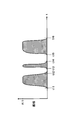
例えば、図20に示すように、時刻t11で指先を"L"の位置で指先をトップパネル120の表面で移動させると駆動制御部240は振幅A11の超音波帯の固有振動をトップパネル120に発生させる。
また、時刻t12で指先が領域163Rから領域166Rに入ると、駆動制御部240は振動素子140をオフにするため、トップパネル120に発生する振動の振幅がゼロになる。
利用者が指先を"K"の位置に向けてさらに移動させて時刻t13で境界Aに達すると、駆動制御部240は振幅A11の超音波帯の固有振動をトップパネル120に発生させる。これにより、利用者は指先の触感で境界Aに達したことを認識することができる。
利用者が指先を"K"の位置に向けてさらに移動させて、時刻t14で境界Aを越えると、駆動制御部240は振動素子140をオフにするため、トップパネル120に発生する振動の振幅がゼロになる。
利用者が指先を"K"の位置に向けてさらに移動させて、時刻t15で領域162R("K"の位置)に入ると、駆動制御部240は振幅A11の超音波帯の固有振動をトップパネル120に発生させる。これにより、利用者は指先の触感で"K"の位置に達したことを認識することができる。
以上のように、境界Aに達したときに、振動素子140をオンにして超音波帯の固有振動をトップパネル120に発生させることによって利用者に境界Aの位置を触感で伝えるようにしてもよい。
なお、操作入力の位置が境界Aに達したときに振動素子140をオンにして超音波帯の固有振動をトップパネル120に発生させるためには、例えば、図10に示す領域166Rのうち、境界Aに沿った幅細い領域を領域162R~165Rと同様に、振動素子140を駆動する領域として割り当てればよい。
また、右利きの人と左利きの人では、フリック操作等の軌跡が異なる場合が有り得る。このため、例えば、利用者が右利きである場合には図10に示す領域163Rを図21に示す領域163R5のように、左側に偏らせてもよい。
また、利用者が左利きである場合には図10に示す領域163Rを図22に示す領域163R6のように、右側に偏らせてもよい。
ここでは、利用者が右利きである場合には左側に偏らせた領域163R5を用い、左利きである場合に右側に偏らせた領域163R6を用いる形態について説明したが、左右のどちらに領域を調整するかは、上述とは逆方向であってもよく、様々な手法が考えられる。
右利きの利用者と左利きの利用者がそれぞれ使いやすくなるように、領域161R~165R(図10参照)を左右非対称にすればよい。
図23には、電子メールを編集する動作モードにおいて、利用者の指先が位置C11にあるアルファベットの"J"を触れた状態から"L"を選択するために、矢印で示すように上向きのフリック操作を行った状態を示す。また、図23には、GUIボタン161A~169Aを示す。
図23では、"A"、"B"、"C"、"2"、"#"の入力を行うためのGUIボタン163AのY軸正方向側に、"J"、"K"、"L"、"5"、"&"のいずれを選択したかを示す円形のサブ表示領域190が表示されている。サブ表示領域190では、フリック操作によって選択された"L"がハイライトされている。
このようなサブ表示領域190が表示される場合においても、上述と同様の手法により、入力ミスを抑制することができる。
以上、本発明の例示的な実施の形態の駆動制御装置、電子機器、駆動制御プログラム、及び駆動制御方法について説明したが、本発明は、具体的に開示された実施の形態に限定されるものではなく、特許請求の範囲から逸脱することなく、種々の変形や変更が可能である。
100 電子機器
110 筐体
120 トップパネル
130 両面テープ
140 振動素子
150 タッチパネル
160 ディスプレイパネル
170 基板
200 制御部
220 アプリケーションプロセッサ
230 通信プロセッサ
240 駆動制御部
250 メモリ
300 駆動制御装置
310 正弦波発生器
320 振幅変調器
110 筐体
120 トップパネル
130 両面テープ
140 振動素子
150 タッチパネル
160 ディスプレイパネル
170 基板
200 制御部
220 アプリケーションプロセッサ
230 通信プロセッサ
240 駆動制御部
250 メモリ
300 駆動制御装置
310 正弦波発生器
320 振幅変調器
Claims (10)
- 表示部と、前記表示部の表示面側に配設され、操作面を有するトップパネルと、前記操作面に行われる操作入力の位置を検出する位置検出部と、前記操作面に振動を発生させる振動素子とを含む電子機器の前記振動素子を駆動する駆動制御装置であって、
前記表示部に表示され、記号の入力に用いられる記号入力部であって、第1記号の入力に用いられる第1入力部と、前記第1入力部の周囲に表示され、互いに異なる複数の第2記号の入力に用いられる複数の第2入力部とを有する記号入力部の画像を表す画像データと、前記第1入力部の表示領域に対応する第1領域と、前記複数の第2入力部の表示領域に対応する複数の第2領域との位置を表す領域データとを格納する格納部と、
前記操作面に超音波帯の固有振動を発生させる駆動信号で前記振動素子を駆動する駆動制御部であって、前記操作入力の位置が前記第1領域及び前記複数の第2領域の外部に移動すると、又は、前記第2領域同士の境界に達すると、前記固有振動の強度が変化するように第1振動パターンで前記振動素子を駆動する駆動制御部と
を含み、
前記第1領域は、前記第1入力部の第1表示領域と等しい、又は、前記第1表示領域を含み、前記第1表示領域よりも大きい領域であり、
前記複数の第2領域は、それぞれ、前記複数の第2入力部の複数の第2表示領域と等しい、又は、前記複数の第2表示領域を含み、前記複数の第2表示領域よりも大きい領域である、駆動制御装置。 - 前記複数の第2入力部は、前記位置検出部によって前記第1入力部の中での前記操作入力が検出されると、前記表示部に表示される、請求項1記載の駆動制御装置。
- 前記複数の第2領域は、前記第1領域の周囲で互いに隣接している、請求項1又は2記載の駆動制御装置。
- 前記駆動制御部は、前記操作入力の位置が一の前記第2領域から前記境界を越えて他の前記第2領域に入ると、前記固有振動の強度が変化するように第2振動パターンで前記振動素子を駆動する、請求項1乃至3のいずれか一項記載の駆動制御装置。
- 前記駆動制御部は、前記操作入力の位置が前記第1領域と前記第2領域との境界に達すると、前記固有振動の強度が変化するように第3振動パターンで前記振動素子を駆動する、請求項1乃至4のいずれか一項記載の駆動制御装置。
- 前記駆動制御部は、前記駆動信号の振幅を制御することによって、前記固有振動の強度が変化するように前記振動素子を駆動する、請求項1乃至5のいずれか一項記載の駆動制御装置。
新 - 前記固有振動は、前記トップパネルの固有振動である、請求項1乃至6のいずれか一項記載の駆動制御装置。
- 表示部と、
前記表示部の表示面側に配設され、操作面を有するトップパネルと、
前記操作面に行われる操作入力の位置を検出する位置検出部と、
前記操作面に振動を発生させる振動素子と、
前記表示部に表示され、記号の入力に用いられる記号入力部であって、第1記号の入力に用いられる第1入力部と、前記第1入力部の周囲に表示され、互いに異なる複数の第2記号の入力に用いられる複数の第2入力部とを有する記号入力部の画像を表す画像データと、前記第1入力部の表示領域に対応する第1領域と、前記複数の第2入力部の表示領域に対応する複数の第2領域との位置を表す領域データとを格納する格納部と、
前記操作面に超音波帯の固有振動を発生させる駆動信号で前記振動素子を駆動する駆動制御部であって、前記操作入力の位置が前記第1領域及び前記複数の第2領域の外部に移動すると、又は、前記第2領域同士の境界に達すると、前記固有振動の強度が変化するように第1振動パターンで前記振動素子を駆動する駆動制御部と
を含み、
前記第1領域は、前記第1入力部の第1表示領域と等しい、又は、前記第1表示領域を含み、前記第1表示領域よりも大きい領域であり、
前記複数の第2領域は、それぞれ、前記複数の第2入力部の複数の第2表示領域と等しい、又は、前記複数の第2表示領域を含み、前記複数の第2表示領域よりも大きい領域である、電子機器。 - 表示部と、前記表示部の表示面側に配設され、操作面を有するトップパネルと、前記操作面に行われる操作入力の位置を検出する位置検出部と、前記操作面に振動を発生させる振動素子とを含む電子機器の前記振動素子を駆動する駆動制御プログラムであって、
前記表示部に表示され、記号の入力に用いられる記号入力部であって、第1記号の入力に用いられる第1入力部と、前記第1入力部の周囲に表示され、互いに異なる複数の第2記号の入力に用いられる複数の第2入力部とを有する記号入力部の画像を表す画像データと、前記第1入力部の表示領域に対応する第1領域と、前記複数の第2入力部の表示領域に対応する複数の第2領域との位置を表す領域データとを格納する格納部を有するコンピュータに、
前記操作面に超音波帯の固有振動を発生させる駆動信号で前記振動素子を駆動することであって、前記操作入力の位置が前記第1領域及び前記複数の第2領域の外部に移動すると、又は、前記第2領域同士の境界に達すると、前記固有振動の強度が変化するように第1振動パターンで前記振動素子を駆動することを実行させ、
前記第1領域は、前記第1入力部の第1表示領域と等しい、又は、前記第1表示領域を含み、前記第1表示領域よりも大きい領域であり、
前記複数の第2領域は、それぞれ、前記複数の第2入力部の複数の第2表示領域と等しい、又は、前記複数の第2表示領域を含み、前記複数の第2表示領域よりも大きい領域である、駆動制御プログラム。 - 表示部と、前記表示部の表示面側に配設され、操作面を有するトップパネルと、前記操作面に行われる操作入力の位置を検出する位置検出部と、前記操作面に振動を発生させる振動素子とを含む電子機器の前記振動素子を駆動する駆動制御方法であって、
前記表示部に表示され、記号の入力に用いられる記号入力部であって、第1記号の入力に用いられる第1入力部と、前記第1入力部の周囲に表示され、互いに異なる複数の第2記号の入力に用いられる複数の第2入力部とを有する記号入力部の画像を表す画像データと、前記第1入力部の表示領域に対応する第1領域と、前記複数の第2入力部の表示領域に対応する複数の第2領域との位置を表す領域データとを格納する格納部を有するコンピュータが、
前記操作面に超音波帯の固有振動を発生させる駆動信号で前記振動素子を駆動する際に、前記操作入力の位置が前記第1領域及び前記複数の第2領域の外部に移動すると、又は、前記第2領域同士の境界に達すると、前記固有振動の強度が変化するように第1振動パターンで前記振動素子を駆動し、
前記第1領域は、前記第1入力部の第1表示領域と等しい、又は、前記第1表示領域を含み、前記第1表示領域よりも大きい領域であり、
前記複数の第2領域は、それぞれ、前記複数の第2入力部の複数の第2表示領域と等しい、又は、前記複数の第2表示領域を含み、前記複数の第2表示領域よりも大きい領域である、駆動制御方法。
Priority Applications (2)
| Application Number | Priority Date | Filing Date | Title |
|---|---|---|---|
| JP2017516238A JP6399216B2 (ja) | 2015-05-01 | 2015-05-01 | 駆動制御装置、電子機器、駆動制御プログラム、及び駆動制御方法 |
| PCT/JP2015/063115 WO2016178273A1 (ja) | 2015-05-01 | 2015-05-01 | 駆動制御装置、電子機器、駆動制御プログラム、及び駆動制御方法 |
Applications Claiming Priority (1)
| Application Number | Priority Date | Filing Date | Title |
|---|---|---|---|
| PCT/JP2015/063115 WO2016178273A1 (ja) | 2015-05-01 | 2015-05-01 | 駆動制御装置、電子機器、駆動制御プログラム、及び駆動制御方法 |
Publications (1)
| Publication Number | Publication Date |
|---|---|
| WO2016178273A1 true WO2016178273A1 (ja) | 2016-11-10 |
Family
ID=57218514
Family Applications (1)
| Application Number | Title | Priority Date | Filing Date |
|---|---|---|---|
| PCT/JP2015/063115 Ceased WO2016178273A1 (ja) | 2015-05-01 | 2015-05-01 | 駆動制御装置、電子機器、駆動制御プログラム、及び駆動制御方法 |
Country Status (2)
| Country | Link |
|---|---|
| JP (1) | JP6399216B2 (ja) |
| WO (1) | WO2016178273A1 (ja) |
Citations (4)
| Publication number | Priority date | Publication date | Assignee | Title |
|---|---|---|---|---|
| JP2008282380A (ja) * | 2007-04-11 | 2008-11-20 | Kota Ogawa | 文字入力システム |
| JP2010224684A (ja) * | 2009-03-19 | 2010-10-07 | Smk Corp | 操作入力装置、制御方法、およびプログラム |
| JP2013073612A (ja) * | 2011-09-29 | 2013-04-22 | Yupiteru Corp | 文字入力システム及びプログラム |
| WO2015045482A1 (ja) * | 2013-09-26 | 2015-04-02 | 富士通株式会社 | 駆動制御装置、電子機器、及び駆動制御方法 |
Family Cites Families (1)
| Publication number | Priority date | Publication date | Assignee | Title |
|---|---|---|---|---|
| JP2002297283A (ja) * | 2001-03-30 | 2002-10-11 | Just Syst Corp | ボタン制御方法およびボタン制御装置 |
-
2015
- 2015-05-01 WO PCT/JP2015/063115 patent/WO2016178273A1/ja not_active Ceased
- 2015-05-01 JP JP2017516238A patent/JP6399216B2/ja not_active Expired - Fee Related
Patent Citations (4)
| Publication number | Priority date | Publication date | Assignee | Title |
|---|---|---|---|---|
| JP2008282380A (ja) * | 2007-04-11 | 2008-11-20 | Kota Ogawa | 文字入力システム |
| JP2010224684A (ja) * | 2009-03-19 | 2010-10-07 | Smk Corp | 操作入力装置、制御方法、およびプログラム |
| JP2013073612A (ja) * | 2011-09-29 | 2013-04-22 | Yupiteru Corp | 文字入力システム及びプログラム |
| WO2015045482A1 (ja) * | 2013-09-26 | 2015-04-02 | 富士通株式会社 | 駆動制御装置、電子機器、及び駆動制御方法 |
Also Published As
| Publication number | Publication date |
|---|---|
| JP6399216B2 (ja) | 2018-10-03 |
| JPWO2016178273A1 (ja) | 2017-12-07 |
Similar Documents
| Publication | Publication Date | Title |
|---|---|---|
| JP5780368B1 (ja) | 駆動制御装置、電子機器、及び駆動制御方法 | |
| JP6161078B2 (ja) | 表示領域エッジでのユーザ入力の検知 | |
| JP6183476B2 (ja) | 電子機器及び駆動制御方法 | |
| WO2015045063A1 (ja) | 駆動制御装置、電子機器、及び駆動制御方法 | |
| JP6645517B2 (ja) | 電子機器、及び、電子機器の駆動方法 | |
| US20160349846A1 (en) | Electronic device, input apparatus, and drive controlling method | |
| TW201447741A (zh) | 對於手勢的回饋 | |
| US20160349847A1 (en) | Electronic device, input apparatus, and drive controlling method | |
| US20180024638A1 (en) | Drive controlling apparatus, electronic device, computer-readable recording medium, and drive controlling method | |
| US10359850B2 (en) | Apparatus and method for switching vibration at panel surface | |
| JP6123850B2 (ja) | 駆動制御装置、電子機器、及び駆動制御方法 | |
| US20160266646A1 (en) | Drive control apparatus, electronic device and drive controlling method | |
| WO2016092644A1 (ja) | 電子機器及び駆動制御方法 | |
| JP6399216B2 (ja) | 駆動制御装置、電子機器、駆動制御プログラム、及び駆動制御方法 | |
| US20180067559A1 (en) | Electronic apparatus and non-transitory recording medium having stored therein | |
| JP6512299B2 (ja) | 駆動制御装置、電子機器、駆動制御プログラム、及び駆動制御方法 | |
| WO2016174760A1 (ja) | 駆動制御装置、電子機器、駆動制御プログラム、及び駆動制御方法 | |
| HK1191705A (en) | Sensing user input at display area edge | |
| HK1191705B (en) | Sensing user input at display area edge | |
| AU2015202408A1 (en) | Drive controlling apparatus, electronic device and drive controlling method |
Legal Events
| Date | Code | Title | Description |
|---|---|---|---|
| 121 | Ep: the epo has been informed by wipo that ep was designated in this application |
Ref document number: 15891280 Country of ref document: EP Kind code of ref document: A1 |
|
| ENP | Entry into the national phase |
Ref document number: 2017516238 Country of ref document: JP Kind code of ref document: A |
|
| NENP | Non-entry into the national phase |
Ref country code: DE |
|
| 122 | Ep: pct application non-entry in european phase |
Ref document number: 15891280 Country of ref document: EP Kind code of ref document: A1 |