WO2016175231A1 - Empilement de piles à combustible - Google Patents
Empilement de piles à combustible Download PDFInfo
- Publication number
- WO2016175231A1 WO2016175231A1 PCT/JP2016/063156 JP2016063156W WO2016175231A1 WO 2016175231 A1 WO2016175231 A1 WO 2016175231A1 JP 2016063156 W JP2016063156 W JP 2016063156W WO 2016175231 A1 WO2016175231 A1 WO 2016175231A1
- Authority
- WO
- WIPO (PCT)
- Prior art keywords
- fuel
- cell stack
- fuel cell
- power generation
- interconnector
- Prior art date
Links
Images


Classifications
-
- H—ELECTRICITY
- H01—ELECTRIC ELEMENTS
- H01M—PROCESSES OR MEANS, e.g. BATTERIES, FOR THE DIRECT CONVERSION OF CHEMICAL ENERGY INTO ELECTRICAL ENERGY
- H01M8/00—Fuel cells; Manufacture thereof
- H01M8/02—Details
-
- H—ELECTRICITY
- H01—ELECTRIC ELEMENTS
- H01M—PROCESSES OR MEANS, e.g. BATTERIES, FOR THE DIRECT CONVERSION OF CHEMICAL ENERGY INTO ELECTRICAL ENERGY
- H01M8/00—Fuel cells; Manufacture thereof
- H01M8/02—Details
- H01M8/0202—Collectors; Separators, e.g. bipolar separators; Interconnectors
-
- H—ELECTRICITY
- H01—ELECTRIC ELEMENTS
- H01M—PROCESSES OR MEANS, e.g. BATTERIES, FOR THE DIRECT CONVERSION OF CHEMICAL ENERGY INTO ELECTRICAL ENERGY
- H01M8/00—Fuel cells; Manufacture thereof
- H01M8/02—Details
- H01M8/0271—Sealing or supporting means around electrodes, matrices or membranes
-
- H—ELECTRICITY
- H01—ELECTRIC ELEMENTS
- H01M—PROCESSES OR MEANS, e.g. BATTERIES, FOR THE DIRECT CONVERSION OF CHEMICAL ENERGY INTO ELECTRICAL ENERGY
- H01M8/00—Fuel cells; Manufacture thereof
- H01M8/24—Grouping of fuel cells, e.g. stacking of fuel cells
- H01M8/2465—Details of groupings of fuel cells
- H01M8/2484—Details of groupings of fuel cells characterised by external manifolds
- H01M8/2485—Arrangements for sealing external manifolds; Arrangements for mounting external manifolds around a stack
-
- H—ELECTRICITY
- H01—ELECTRIC ELEMENTS
- H01M—PROCESSES OR MEANS, e.g. BATTERIES, FOR THE DIRECT CONVERSION OF CHEMICAL ENERGY INTO ELECTRICAL ENERGY
- H01M8/00—Fuel cells; Manufacture thereof
- H01M8/10—Fuel cells with solid electrolytes
- H01M8/12—Fuel cells with solid electrolytes operating at high temperature, e.g. with stabilised ZrO2 electrolyte
-
- Y—GENERAL TAGGING OF NEW TECHNOLOGICAL DEVELOPMENTS; GENERAL TAGGING OF CROSS-SECTIONAL TECHNOLOGIES SPANNING OVER SEVERAL SECTIONS OF THE IPC; TECHNICAL SUBJECTS COVERED BY FORMER USPC CROSS-REFERENCE ART COLLECTIONS [XRACs] AND DIGESTS
- Y02—TECHNOLOGIES OR APPLICATIONS FOR MITIGATION OR ADAPTATION AGAINST CLIMATE CHANGE
- Y02E—REDUCTION OF GREENHOUSE GAS [GHG] EMISSIONS, RELATED TO ENERGY GENERATION, TRANSMISSION OR DISTRIBUTION
- Y02E60/00—Enabling technologies; Technologies with a potential or indirect contribution to GHG emissions mitigation
- Y02E60/30—Hydrogen technology
- Y02E60/50—Fuel cells
Definitions
- the technology disclosed in this specification relates to a fuel cell stack.
- a solid oxide fuel cell (hereinafter also referred to as “SOFC”) is generally used in the form of a fuel cell stack including a plurality of power generation units arranged in a predetermined direction (hereinafter also referred to as “array direction”). Is done.
- the power generation unit is the minimum unit of power generation, and includes an electrolyte layer and an air electrode and a fuel electrode facing each other in the arrangement direction with the electrolyte layer interposed therebetween.
- the fuel cell stack has a plurality of bolt holes extending in the arrangement direction over a plurality of power generation units, and is fastened by bolts inserted into the plurality of bolt holes, respectively.
- a plurality of gas flow paths (also called “manifolds”) extending over a plurality of power generation units are formed.
- Fuel gas and oxidant gas are supplied to the fuel chamber facing the fuel electrode and the air chamber facing the air electrode of each power generation unit through each gas flow path, respectively.
- Fuel off-gas and oxidant off-gas are discharged from the chamber, respectively.
- a form of a fuel cell stack that uses the above-described plurality of bolt holes also as the above-described plurality of gas flow paths is known.
- the space formed between the inner peripheral surface of the bolt hole and the outer peripheral surface of the shaft portion of the bolt inserted into the bolt hole, or the space formed inside the shaft portion of the bolt is a gas flow path.
- the contaminant contained in the bolt is carried to the fuel chamber or the air chamber by the gas flow in the gas flow path, and may adhere to the fuel electrode or the air electrode, causing a contamination phenomenon that decreases the reaction rate of the electrode. is there.
- each bolt when the temperature of the gas flowing through each gas flow path is different from each other, each bolt is exposed to a gas having a different temperature, so that a difference occurs in the deformation amount due to thermal expansion of each bolt, and the fuel cell stack
- the pressure hereinafter also referred to as “contact pressure”
- contact pressure for holding the fuel cell stack in the arrangement direction varies in the surface direction (direction perpendicular to the arrangement direction), and gas may leak from the inside of the fuel cell stack to the outside.
- each power generation unit is disposed between the metal interconnector, the metal separator that partitions the fuel chamber and the air chamber, and the through hole that constitutes the fuel chamber between the separator and the interconnector.
- the fuel gas may leak to the bolt hole through the separator and the frame member or between the frame member and the interconnector. If the fuel gas leaks into the bolt hole, the efficiency of the fuel cell stack decreases, which is not preferable.
- the packing formed of the metal foil is disposed between the frame member and the interconnector. However, in this configuration, the leakage of the fuel gas to the bolt hole cannot be sufficiently suppressed.
- each power generation unit includes a metal interconnector, a metal separator, and a metal frame member that is disposed between the separator and the interconnector and has a through hole that forms an air chamber.
- the oxidant gas may leak to the bolt hole through between the separator and the frame member or between the frame member and the interconnector.
- SOFC sulfur-oxide-semiconductor
- a fuel cell stack disclosed in the present specification includes a plurality of power generation units arranged side by side in a first direction and a plurality of bolt holes extending in the first direction across the plurality of power generation units.
- Each of the power generating units includes an electrolyte layer and an air electrode and a fuel electrode facing each other in the first direction with the electrolyte layer interposed therebetween.
- a single cell including the single cell, a metal interconnector facing the single cell in the first direction, a through hole is formed, and a portion surrounding the through hole is joined to a peripheral portion of the single cell, and the air
- a metal separator that divides an air chamber facing the electrode and a fuel chamber facing the fuel electrode, and is disposed between the separator and the interconnector to constitute the fuel chamber or the air chamber
- a plurality of gas flow paths extending over the plurality of power generation units are formed in the fuel cell stack.
- a first seal portion for joining and sealing at least one of between the separator and the frame member and between the frame member and the interconnector. It is formed so as to surround the bolt hole.
- the first seal portion is formed so as to surround each bolt hole, gas leakage from the gas flow path, the fuel chamber, or the air chamber to the bolt hole is suppressed. And a reduction in the power generation efficiency of the fuel cell stack can be suppressed.
- the first seal portion seals both between the separator and the frame member and between the frame member and the interconnector. It is good also as a structure. According to this fuel cell stack, the first seal portion is formed so as to seal both between the separator and the frame member and between the frame member and the interconnector. Leakage of gas from the chamber or the air chamber to the bolt hole can be suppressed, and a reduction in power generation efficiency of the fuel cell stack can be effectively suppressed.
- the other interconnect which is the interconnector included in the separator included in one power generation unit and the other power generation unit located next to the one power generation unit in the first direction.
- a second seal portion that is joined and sealed so as to surround at least one of the gas flow paths may be formed between the connector and the connector.
- the fuel cell stack may further include a third seal portion that joins and seals at least one of the separator and the frame member, and the frame member and the interconnector,
- the third seal portion is continuous so as to pass between each of the plurality of gas flow paths and the outer peripheral edge of each power generation unit and to surround the plurality of gas flow paths in the first direction view. It is good also as a structure characterized by being formed. According to the fuel cell stack, since the third seal portion is continuously formed so as to surround the plurality of gas flow paths, the gas flows from the plurality of gas flow paths to which the gas should originally flow to the outside of the fuel cell stack. Can be suppressed, and a decrease in power generation efficiency of the fuel cell stack can be further effectively suppressed.
- the third seal portion may be formed along an outer peripheral shape of each power generation unit. According to the fuel cell stack, since the third seal portion is formed along the outer peripheral shape of each power generation unit, the gas flow path, the fuel chamber or the air chamber where the gas should originally flow from the fuel cell stack to the outside. Gas leakage can be suppressed, and a reduction in power generation efficiency of the fuel cell stack can be further effectively suppressed.
- the first seal portion may be a welded portion. According to this fuel cell stack, since the first seal part is formed by a welded part that can be expected to have high sealing performance, it is more reliable that gas leaks from the gas flow path, the fuel chamber, or the air chamber to the bolt hole. It is possible to suppress the decrease in power generation efficiency of the fuel cell stack more effectively.
- the technology disclosed in this specification can be realized in various forms, for example, in the form of a fuel cell stack, a power generation module including the fuel cell stack, a fuel cell system including the power generation module, and the like. Is possible.
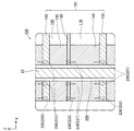
- FIG. 1 is a perspective view showing an external configuration of a fuel cell stack 100.
- FIG. 2 is an explanatory diagram showing an XY plane configuration on the upper side of the fuel cell stack 100.
- FIG. 2 is an explanatory view showing an XY plane configuration on the lower side of the fuel cell stack 100.
- FIG. 4 is an explanatory diagram showing an XZ cross-sectional configuration of a fuel cell stack 100 at a position IV-IV in FIGS. 1 to 3.
- FIG. 4 is an explanatory diagram showing a YZ cross-sectional configuration of the fuel cell stack 100 at the position VV in FIGS. 1 to 3. It is explanatory drawing which shows XZ cross-section structure of the two electric power generation units 102 adjacent to each other in the same position as the cross section shown in FIG.
- FIG. 7 is an explanatory diagram showing an XY cross-sectional configuration of a power generation unit at a position of VIII-VIII in FIG. 6.
- FIG. 7 is an explanatory diagram showing an XY cross-sectional configuration of a power generation unit at a position IX-IX in FIG. 6.
- FIG. 7 is an explanatory diagram showing an XY cross-sectional configuration of a power generation unit at a position XX in FIG.
- FIG. 7 is an explanatory diagram showing an XY cross-sectional configuration of a power generation unit 102 at a position XI-XI in FIG. 6.
- FIG. 5 is an explanatory diagram showing a configuration of a gas seal at a position of a fuel electrode side frame 140.
- FIGS. 1 to 5 are explanatory views schematically showing the configuration of the fuel cell stack 100 in the present embodiment.
- FIG. 1 shows an external configuration of the fuel cell stack 100
- FIG. 2 shows a planar configuration of the upper side of the fuel cell stack 100
- FIG. 4 shows a cross-sectional configuration of the fuel cell stack 100 at the position IV-IV in FIGS. 1 to 3
- FIG. 5 shows a cross-sectional configuration in FIGS.
- a cross-sectional configuration of the fuel cell stack 100 at the position VV is shown.
- XYZ axes orthogonal to each other for specifying the direction are shown.
- the positive direction of the Z axis is referred to as the upward direction
- the negative direction of the Z axis is referred to as the downward direction.
- the fuel cell stack 100 is actually different from such an orientation. It may be installed. The same applies to FIG. 6 and subsequent figures.
- the fuel cell stack 100 includes a plurality (seven in this embodiment) of power generation units 102 and a pair of end plates 104 and 106.
- the seven power generation units 102 are arranged side by side in a predetermined arrangement direction (vertical direction in the present embodiment).
- the pair of end plates 104 and 106 are arranged so as to sandwich the seven power generation units 102 from above and below.
- the arrangement direction (vertical direction) corresponds to the first direction in the claims.
- holes that penetrate in the vertical direction are formed in the four corners of the outer periphery of each power generation unit 102 and the end plates 104 and 106 around the Z direction, and are formed in each layer and correspond to each other.
- the holes communicate with each other in the vertical direction to form a bolt hole 109 extending in the vertical direction from one end plate 104 to the other end plate 106.
- Bolts 22 are inserted into the respective bolt holes 109, and the fuel cell stack 100 is fastened by the bolts 22 and nuts 24 fitted on both sides of the bolts 22.
- a hole penetrating in the vertical direction is formed in the vicinity of the midpoint of the outer periphery around the Z direction of each power generation unit 102 and the lower end plate 106.
- holes corresponding to each other formed in each layer communicate with each other in the vertical direction to form a communication hole 108 extending in the vertical direction across each power generation unit 102 and the end plate 106.
- the midpoint of one side (the X-axis positive direction side of two sides parallel to the Y-axis) on the outer periphery around the Z-direction of the fuel cell stack 100
- the communication hole 108 located in the vicinity functions as an oxidant gas introduction manifold 161 that is a gas passage through which the oxidant gas OG is introduced from the outside of the fuel cell stack 100 and supplies the oxidant gas OG to each power generation unit 102.
- the communication hole 108 located near the midpoint of the opposite side (the side on the negative X-axis side of the two sides parallel to the Y-axis) is not yet discharged from each power generation unit 102.
- oxidant gas discharge manifold 162 that is a gas flow path for discharging the oxidant off-gas OOG, which is a reaction oxidant gas OG, to the outside of the fuel cell stack 100.
- OOG oxidant off-gas
- OG reaction oxidant gas
- one side of the outer periphery of the fuel cell stack 100 around the Z direction (the side on the Y axis positive direction side of the two sides parallel to the X axis)
- the communication hole 108 located in the vicinity of the midpoint functions as a fuel gas introduction manifold 171 that is a gas passage through which the fuel gas FG is introduced from the outside of the fuel cell stack 100 and supplies the fuel gas FG to each power generation unit 102.
- the communication hole 108 located near the midpoint of the side opposite to the side (the side on the Y axis negative direction side of the two sides parallel to the X axis) is unreacted discharged from each power generation unit 102.
- a fuel gas discharge manifold 172 that is a gas flow path for discharging the fuel off-gas FOG that is the fuel gas FG to the outside of the fuel cell stack 100.
- the fuel gas FG for example, hydrogen-rich gas obtained by reforming city gas is used.
- the fuel cell stack 100 is provided with four gas passage members 27.
- Each gas passage member 27 has a hollow cylindrical main body portion 28 and a hollow cylindrical branch portion 29 branched from the side surface of the main body portion 28.
- the hole of the branch part 29 communicates with the hole of the main body part 28.
- a gas pipe (not shown) is connected to the branch portion 29 of each gas passage member 27.
- the hole of the main body portion 28 of the gas passage member 27 disposed at the position of the oxidant gas introduction manifold 161 communicates with the oxidant gas introduction manifold 161.
- the hole of the main body 28 of the gas passage member 27 arranged at the position communicates with the oxidant gas discharge manifold 162. Further, as shown in FIG.
- An insulating sheet 26 is interposed between each gas passage member 27 and the surface of the end plate 106.
- the insulating sheet 26 is made of, for example, a mica sheet, a ceramic fiber sheet, a ceramic powder sheet, a glass sheet, a glass ceramic composite agent, or the like.
- the pair of end plates 104 and 106 are rectangular flat plate-shaped conductive members, and are formed of, for example, stainless steel.
- One end plate 104 is disposed on the upper side of the power generation unit 102 located on the uppermost side, and the other end plate 106 is disposed on the lower side of the power generation unit 102 located on the lowermost side.
- a plurality of power generation units 102 are held in a pressed state by a pair of end plates 104 and 106.
- the upper end plate 104 functions as a positive output terminal of the fuel cell stack 100
- the lower end plate 106 functions as a negative output terminal of the fuel cell stack 100.
- FIG. 10 shows a cross-sectional configuration of two power generation units 102 adjacent to each other at the same position as the cross section shown in FIG. 4, and FIG. 7 shows adjacent cross sections at the same position as the cross section shown in FIG.
- FIG. 8 shows a cross-sectional configuration of the power generation unit 102 at the position of VIII-VIII in FIG. 6, and
- FIG. 9 shows a cross-sectional configuration of the power generation unit 102 in FIG. 10 shows a cross-sectional configuration of the power generation unit 102 at the position IX
- FIG. 10 shows a cross-sectional configuration of the power generation unit 102 at the position XX in FIG. 6, and FIG.
- a cross-sectional configuration of the power generation unit 102 at the position XI-XI is shown.
- the power generation unit 102 which is the minimum unit of power generation includes a single cell 110, a separator 120, an air electrode side frame 130, an air electrode side current collector 134, and a fuel electrode side frame. 140, a fuel electrode side current collector 144, and a pair of interconnectors 150 constituting the uppermost layer and the lowermost layer of the power generation unit 102.
- the separator 120, the air electrode side frame 130, the fuel electrode side frame 140, and the interconnector 150 around the Z direction holes corresponding to the bolt holes 109 into which the bolts 22 are inserted and functions as manifolds.
- a hole corresponding to the communication hole 108 is formed (see FIGS. 8 to 11).
- the single cell 110 includes an electrolyte layer 112 and an air electrode (cathode) 114 and a fuel electrode (anode) 116 that face each other in the vertical direction (the arrangement direction in which the power generation units 102 are arranged) with the electrolyte layer 112 interposed therebetween.
- the single cell 110 of the present embodiment is a fuel electrode-supported single cell that supports the electrolyte layer 112 and the air electrode 114 with the fuel electrode 116.
- the electrolyte layer 112 is a rectangular flat plate-like member, such as YSZ (yttria stabilized zirconia), ScSZ (scandia stabilized zirconia), SDC (samarium doped ceria), GDC (gadolinium doped ceria), perovskite oxide, etc.
- the solid oxide is formed.
- the air electrode 114 is a rectangular flat plate-shaped member, and is formed of, for example, a perovskite oxide (for example, LSCF (lanthanum strontium cobalt iron oxide), LSM (lanthanum strontium manganese oxide), LNF (lanthanum nickel iron)). ing.
- the fuel electrode 116 is a rectangular flat plate-like member, and is formed of, for example, Ni (nickel), cermet made of Ni and ceramic particles, Ni-based alloy, or the like.
- the single cell 110 (power generation unit 102) of the present embodiment is a solid oxide fuel cell (SOFC) that uses a solid oxide as an electrolyte.
- SOFC solid oxide fuel cell
- the separator 120 is a frame-like member in which a rectangular hole 121 penetrating in the vertical direction is formed near the center, and is made of, for example, metal.
- the peripheral part of the hole 121 in the separator 120 is opposed to the peripheral part of the surface of the electrolyte layer 112 on the air electrode 114 side.
- the separator 120 is bonded to the electrolyte layer 112 (single cell 110) by a bonding portion 124 formed of a brazing material (for example, Ag brazing) disposed in the facing portion.
- the separator 120 divides the air chamber 166 facing the air electrode 114 and the fuel chamber 176 facing the fuel electrode 116, and gas leaks from one electrode side to the other electrode side in the peripheral portion of the single cell 110. It is suppressed.
- the single cell 110 to which the separator 120 is bonded is also referred to as a single cell with a separator.
- the interconnector 150 is a rectangular flat plate-shaped conductive member, and is formed of, for example, ferritic stainless steel.
- the interconnector 150 is disposed so as to face the single cell 110 in the arrangement direction.
- the interconnector 150 ensures electrical continuity between the power generation units 102 and prevents reaction gas from being mixed between the power generation units 102.
- one interconnector 150 is shared by two adjacent power generation units 102. That is, the upper interconnector 150 in a power generation unit 102 is the same member as the lower interconnector 150 in another power generation unit 102 adjacent to the upper side of the power generation unit 102.
- the power generation unit 102 located at the top in the fuel cell stack 100 does not include the upper interconnector 150 and is located at the bottom.
- the power generation unit 102 does not include the lower interconnector 150 (see FIGS. 4 and 5).
- the air electrode side frame 130 is a frame-like member in which a rectangular hole 131 penetrating in the vertical direction is formed near the center.
- an insulator such as mica It is formed by.
- the air electrode side frame 130 is disposed between the separator 120 and the interconnector 150, and is opposed to the peripheral edge of the surface of the separator 120 opposite to the side facing the electrolyte layer 112 and the air electrode 114 of the interconnector 150. In contact with the peripheral edge of the surface on the side to be
- the hole 131 of the air electrode side frame 130 forms an air chamber 166 that faces the air electrode 114.
- the pair of interconnectors 150 included in the power generation unit 102 is electrically insulated by the air electrode side frame 130.
- the air electrode side frame 130 has an oxidant gas supply communication hole 132 communicating the oxidant gas introduction manifold 161 and the air chamber 166, and an oxidant gas communicating the air chamber 166 and the oxidant gas discharge manifold 162.
- a discharge communication hole 133 is formed.
- the fuel electrode side frame 140 is a frame-like member in which a rectangular hole 141 penetrating in the vertical direction is formed near the center, and is formed of, for example, metal. Yes.
- the fuel electrode side frame 140 is disposed between the separator 120 and the interconnector 150, and has a peripheral edge on the surface of the separator 120 facing the electrolyte layer 112 and a surface of the interconnector 150 facing the fuel electrode 116. It is in contact with the peripheral part.
- the hole 141 of the fuel electrode side frame 140 forms a fuel chamber 176 that faces the fuel electrode 116.
- the fuel electrode side frame 140 has a fuel gas supply communication hole 142 that connects the fuel gas introduction manifold 171 and the fuel chamber 176, and a fuel gas discharge communication hole 143 that connects the fuel chamber 176 and the fuel gas discharge manifold 172. And are formed.
- the fuel electrode side frame 140 corresponds to a frame member in the claims.
- the air electrode side current collector 134 is disposed in the air chamber 166.
- the air electrode side current collector 134 is composed of a plurality of substantially quadrangular columnar conductive members arranged at predetermined intervals, and is made of, for example, ferritic stainless steel.
- the air electrode side current collector 134 is brought into contact with the surface of the air electrode 114 opposite to the side facing the electrolyte layer 112 and the surface of the interconnector 150 facing the air electrode 114, whereby the air electrode 114 and the interconnector 150 are electrically connected.
- the air electrode side current collector 134 and the interconnector 150 may be formed as an integral member.
- the fuel electrode side current collector 144 is disposed in the fuel chamber 176.
- the fuel electrode side current collector 144 includes an interconnector facing portion 146, a plurality of electrode facing portions 145, and a connecting portion 147 that connects each electrode facing portion 145 and the interconnector facing portion 146. Or nickel alloy, stainless steel or the like.
- Each electrode facing portion 145 contacts the surface of the fuel electrode 116 opposite to the side facing the electrolyte layer 112, and the interconnector facing portion 146 contacts the surface of the interconnector 150 facing the fuel electrode 116. To do. Therefore, the fuel electrode side current collector 144 electrically connects the fuel electrode 116 and the interconnector 150.
- a spacer 149 made of, for example, mica is disposed between the electrode facing portion 145 and the interconnector facing portion 146. Therefore, the fuel electrode side current collector 144 follows the deformation of the power generation unit 102 due to the temperature cycle or reaction gas pressure fluctuation, and the fuel electrode 116 and the interconnector 150 are electrically connected via the fuel electrode side current collector 144. Maintained well.
- the oxidant gas is connected via a gas pipe (not shown) connected to the branch portion 29 of the gas passage member 27 provided at the position of the oxidant gas introduction manifold 161.
- a gas pipe (not shown) connected to the branch portion 29 of the gas passage member 27 provided at the position of the oxidant gas introduction manifold 161.
- the oxidant gas OG is supplied to the oxidant gas introduction manifold 161 through the branch part 29 of the gas passage member 27 and the hole of the main body part 28, and each power generation unit is supplied from the oxidant gas introduction manifold 161.
- 102 is supplied to the air chamber 166 through the oxidant gas supply communication hole 132. Further, as shown in FIGS.
- the fuel gas is supplied via a gas pipe (not shown) connected to the branch portion 29 of the gas passage member 27 provided at the position of the fuel gas introduction manifold 171.
- a gas pipe (not shown) connected to the branch portion 29 of the gas passage member 27 provided at the position of the fuel gas introduction manifold 171.
- the fuel gas FG is supplied to the fuel gas introduction manifold 171 through the branch portion 29 of the gas passage member 27 and the hole of the main body portion 28, and the fuel of each power generation unit 102 is supplied from the fuel gas introduction manifold 171.
- the fuel is supplied to the fuel chamber 176 through the gas supply communication hole 142.
- each power generation unit 102 When the oxidant gas OG is supplied to the air chamber 166 of each power generation unit 102 and the fuel gas FG is supplied to the fuel chamber 176, power is generated by an electrochemical reaction between the oxidant gas OG and the fuel gas FG in the single cell 110. Is called. This power generation reaction is an exothermic reaction.
- the air electrode 114 of the single cell 110 is electrically connected to one interconnector 150 via the air electrode side current collector 134, and the fuel electrode 116 is connected via the fuel electrode side current collector 144.
- the other interconnector 150 is electrically connected.
- the plurality of power generation units 102 included in the fuel cell stack 100 are electrically connected in series.
- each power generation unit 102 electrical energy generated in each power generation unit 102 is taken out from the end plates 104 and 106 that function as output terminals of the fuel cell stack 100. Since SOFC generates power at a relatively high temperature (for example, 700 ° C. to 1000 ° C.), the fuel cell stack 100 is heated by a heater (after the start-up until the high temperature can be maintained by the heat generated by the power generation. (Not shown).
- the oxidant off-gas OOG that is the oxidant gas OG that has not been used for the power generation reaction in each power generation unit 102 passes through the oxidant gas discharge communication hole 133 from the air chamber 166.
- the gas is discharged to the oxidant gas discharge manifold 162 and further connected to the branch part 29 through the holes of the main body part 28 and the branch part 29 of the gas passage member 27 provided at the position of the oxidant gas discharge manifold 162. It is discharged to the outside of the fuel cell stack 100 through piping (not shown).
- the fuel off-gas FOG that is the fuel gas FG that has not been used for the power generation reaction in each power generation unit 102 passes through the fuel gas discharge communication hole 143 from the fuel chamber 176, as shown in FIGS.
- Gas piping (shown in the figure) connected to the branching portion 29 through the holes of the main body portion 28 and the branching portion 29 of the gas passage member 27 that is discharged to the fuel gas discharge manifold 172 and further provided at the position of the fuel gas discharge manifold 172. Is not discharged to the outside of the fuel cell stack 100.
- the contaminants contained in the bolts 22 are transferred to the respective manifolds. It is possible to avoid the occurrence of a contamination phenomenon that is carried to the fuel chamber 176 and the air chamber 166 by the gas flow in the gas and adheres to the fuel electrode 116 and the air electrode 114 and decreases the reaction speed of the electrodes.
- a difference in deformation amount due to thermal expansion of each bolt 22 occurs due to exposure to gases at different temperatures, the contact pressure of the fuel cell stack 100 varies in the surface direction of the fuel cell stack 100, and the gas flows from the inside of the fuel cell stack 100 to the outside. Can be avoided.
- the air electrode side frame 130 included in each power generation unit 102 in the fuel cell stack 100 functions as a so-called compression seal.
- the air electrode side frame 130 is sandwiched between the separator 120 and the interconnector 150 and is compressed, thereby closely contacting the surfaces of the separator 120 and the interconnector 150.
- a fuel gas introduction manifold 171 and a fuel gas discharge manifold 172 are provided between the separator 120 and the interconnector 150 facing the separator 120 with the air electrode side frame 130 interposed therebetween.
- a glass seal 240 is provided so as to surround each of these.
- the glass seal 240 is connected to the fuel gas FG (from the fuel gas introduction manifold 171 and the fuel gas discharge manifold 172 via the interface between the air electrode side frame 130 and the separator 120 and the interface between the air electrode side frame 130 and the interconnector 150.
- the leakage of the fuel off gas FOG is suppressed.
- the glass seal 240 is an insulator, the provision of the glass seal 240 does not hinder the electrical insulation between the pair of interconnectors 150 included in the power generation unit 102.
- the glass seal 240 is not provided around the oxidant gas introduction manifold 161 and the oxidant gas discharge manifold 162.
- the glass seal 240 corresponds to the second seal portion in the claims.
- FIG. 12 is an explanatory diagram showing the configuration of the gas seal at the position of the fuel electrode side frame 140.
- FIG. 12 shows a part of the cross-sectional configuration of the fuel cell stack 100 at the position XII-XII in FIGS. 1 to 3 and FIGS. 8 to 11.
- a welded portion 230 is formed by laser welding between the fuel electrode side frame 140 and the separator 120 adjacent to the upper side of the fuel electrode side frame 140.
- a welded portion 230 is also formed by welding between the fuel electrode side frame 140 and the interconnector 150 adjacent to the lower side of the fuel electrode side frame 140.
- the welded portion 230 includes an outer periphery welded portion 233 formed along the outer periphery shape of each power generation unit 102.
- the outer periphery welding part 233 is formed along the outer periphery of the power generation unit 102, and each communication hole 108 and each bolt hole 109 formed in each power generation unit 102 exists inside the outer periphery welding part 233.
- a fuel gas FG (or fuel) from the inside to the outside of the fuel cell stack 100 via the interface between the fuel electrode side frame 140 and the separator 120 and the interface between the fuel electrode side frame 140 and the interconnector 150 by the outer periphery welding portion 233.
- Off-gas FOG Off-gas FOG
- the welded portion 230 includes a manifold periphery weld 235 formed so as to surround each of the oxidant gas introduction manifold 161 and the oxidant gas discharge manifold 162.
- the manifold periphery weld 235 By means of the manifold periphery weld 235, the oxidant gas introduction manifold 161 and the oxidant gas discharge manifold 162 are connected via the interface between the fuel electrode side frame 140 and the separator 120 and the interface between the fuel electrode side frame 140 and the interconnector 150. Leakage of the oxidant gas OG (or oxidant off-gas OOG) is suppressed.
- the separator 120 may have a hole or the fuel gas supply Since the communication hole 142 and the fuel gas discharge communication hole 143 may be blocked, it is difficult to weld the members. For this reason, the welded portion 230 is not formed around the fuel gas introduction manifold 171 and the fuel gas discharge manifold 172.
- the welded portion 230 includes a bolt-around welded portion 231 formed so as to surround each bolt hole 109 along the outer peripheral shape of the bolt hole 109.
- the fuel chamber 176, the fuel gas introduction manifold 171, and the fuel gas discharge manifold 172 are connected through the interface between the fuel electrode side frame 140 and the separator 120 and the interface between the fuel electrode side frame 140 and the interconnector 150 by the welding part 231 around the bolt.
- the leakage of the fuel gas FG (or fuel off-gas FOG) from the through hole to the bolt hole 109 is suppressed.
- the bolt circumference welded portion 231 corresponds to the first seal portion in the claims.
- a plurality of manifolds (communication holes 108) extending over the plurality of power generation units 102 are formed in addition to the plurality of bolt holes 109. Further, a welded portion 230 that seals between the separator 120 and the fuel electrode side frame 140 and between the fuel electrode side frame 140 and the interconnector 150 is formed. A bolt periphery weld 231 formed to surround the periphery is included. Therefore, in the fuel cell stack 100 of this embodiment, it is possible to suppress the leakage of the fuel gas FG (or the fuel off-gas FOG) from the fuel gas introduction manifold 171, the fuel gas discharge manifold 172, and the fuel chamber 176 to the bolt hole 109.
- the fuel gas FG or the fuel off-gas FOG
- the gas seal at the position of the welded portion 231 around the bolt is formed by the welded portion 230 that can be expected to have a high sealing performance, and thus gas leakage to the bolt hole 109 is more reliably suppressed. Therefore, it is possible to effectively suppress a decrease in power generation efficiency of the fuel cell stack 100.
- the fuel gas introduction manifold 171 and the fuel gas discharge manifold 172 are disposed between the separator 120 and the interconnector 150 facing the separator 120 with the air electrode side frame 130 interposed therebetween. Since the glass seal 240 is provided so as to surround each of the two, the fuel gas introduction manifold via the interface between the air electrode side frame 130 and the separator 120 and the interface between the air electrode side frame 130 and the interconnector 150 is provided.
- the leakage of the fuel gas FG (or the fuel off-gas FOG) from the fuel gas exhaust manifold 172 or the fuel gas discharge manifold 172 can be suppressed, and the reduction in power generation efficiency of the fuel cell stack 100 can be more effectively suppressed.
- the welded portion 230 includes the outer peripheral welded portion 233 formed along the outer peripheral shape of each power generation unit 102, the interface between the fuel electrode side frame 140 and the separator 120 or the like Leakage of the fuel gas FG (or fuel off-gas FOG) from the inside of the fuel cell stack 100 to the outside via the interface between the fuel electrode side frame 140 and the interconnector 150 is suppressed, and the power generation efficiency of the fuel cell stack 100 is reduced. Can be more effectively suppressed.
- all of the bolt periphery welding part 231, the glass seal 240, and the outer periphery welding part 233 exhibit the sealing function between members by joining between the members to be sealed.
- the welded part 231 around the bolt, the glass seal 240, and the outer periphery welded part 233 are distinguished from those that exhibit a sealing function between members by being sandwiched and compressed between the members to be sealed (so-called compression seals).
- the welded portion 230 is formed both between the fuel electrode side frame 140 and the separator 120 and between the fuel electrode side frame 140 and the interconnector 150. It is good also as being formed only in one of these.
- the welding part 230 is supposed to include the bolt periphery welding part 231, the outer periphery welding part 233, and the manifold periphery welding part 235, the welding part 230 is the outer periphery welding part 233 and the manifold periphery welding part 235. And at least one of them may not be included.
- the welded portion 230 is formed by laser welding, but may be formed by a welding method other than laser welding. Further, a seal configuration other than welding (for example, a glass seal) may be formed in place of the welded portion 230 at the position where the welded portion 230 is formed.
- the outer periphery welding part 233 is formed along the outer periphery shape of each electric power generation unit 102, the outer periphery welding part 233 is not necessarily formed along the outer periphery shape of each electric power generation unit 102.
- the first direction Z direction
- it passes between each manifold 171, 172, 161, 162 and the outer peripheral edge of each power generation unit 102, and all the manifolds 171, 172, 161 , 162 as long as they are continuously formed so as to surround them.
- the glass seals 240 surrounding the fuel gas introduction manifold 171 and the fuel gas discharge manifold 172 are provided.
- the glass seal 240 is formed around the fuel gas introduction manifold 171 and the fuel gas. It may be provided only on one side around the discharge manifold 172. Further, the glass seal 240 may be provided around the oxidant gas introduction manifold 161 and the oxidant gas discharge manifold 162. Further, instead of the glass seal 240, a seal configuration other than the glass seal may be formed at a position where the glass seal 240 is formed.
- the gas seal is secured by welding at the position of the fuel electrode side frame 140.
- the gas seal is secured by welding at the position of the air electrode side frame 130 as well. Good.
- the number of power generation units 102 included in the fuel cell stack 100 is merely an example, and the number of power generation units 102 is appropriately determined according to the output voltage required for the fuel cell stack 100 or the like.
- the nuts 24 are fitted on both sides of the bolt 22, but the bolt 22 has a head, and the nut 24 is fitted only on the opposite side of the head of the bolt 22. Also good.
- the end plates 104 and 106 function as output terminals.
- separate members for example, the end plate 104 connected to the end plates 104 and 106, respectively.
- 106 and the power generation unit 102 may function as output terminals.
- one interconnector 150 is shared by two adjacent power generation units 102.
- Two power generation units 102 may be provided with respective interconnectors 150.
- the upper interconnector 150 of the uppermost power generation unit 102 in the fuel cell stack 100 and the lower interconnector 150 of the lowermost power generation unit 102 are omitted. These interconnectors 150 may be provided without being omitted.
- the fuel electrode side current collector 144 may have the same configuration as the air electrode side current collector 134, and the fuel electrode side current collector 144 and the adjacent interconnector 150 are an integral member. It may be. Further, the fuel electrode side frame 140 instead of the air electrode side frame 130 may be an insulator. The air electrode side frame 130 and the fuel electrode side frame 140 may have a multilayer structure.
- each member in the above embodiment is merely an example, and each member may be formed of other materials.
- the city gas is reformed to obtain the hydrogen-rich fuel gas FG
- the fuel gas FG may be obtained from other raw materials such as LP gas, kerosene, methanol, gasoline, Pure hydrogen may be used as the fuel gas FG.
- a reaction preventing layer formed of, for example, ceria is provided between the electrolyte layer 112 and the air electrode 114 so that zirconium or the like in the electrolyte layer 112 reacts with strontium or the like in the air electrode 114.
- An increase in electrical resistance between the electrolyte layer 112 and the air electrode 114 may be suppressed.
- the solid oxide fuel cell has been described as an example.
- the present invention can be applied to a solid polymer fuel cell (PEFC), a phosphoric acid fuel cell (PAFC), a molten carbonate type. It can also be applied to other types of fuel cells such as fuel cells (MCFC).
- PEFC solid polymer fuel cell
- PAFC phosphoric acid fuel cell
- MCFC fuel cells
Landscapes
- Life Sciences & Earth Sciences (AREA)
- Engineering & Computer Science (AREA)
- Manufacturing & Machinery (AREA)
- Sustainable Development (AREA)
- Sustainable Energy (AREA)
- Chemical & Material Sciences (AREA)
- Chemical Kinetics & Catalysis (AREA)
- Electrochemistry (AREA)
- General Chemical & Material Sciences (AREA)
- Fuel Cell (AREA)
Abstract
La présente invention empêche les fuites de gaz depuis un trajet d'écoulement de gaz, une chambre de carburant, ou une chambre à air, dans un trou de boulon. L'empilement de piles à combustible selon la présente invention comprend une pluralité d'unités de génération d'énergie et des boulons insérés dans chacun d'une pluralité de trous de boulon, l'empilement de piles à combustible étant fixé par chacun des boulons. Chacune des unités de génération de puissance contient : une cellule unique ; un interconnecteur métallique ; un séparateur métallique séparant une chambre à air et une chambre de carburant ; et un élément de cadre métallique disposé entre le séparateur et l'interconnecteur, dans lequel un trou traversant a été formé pour constituer la chambre de carburant ou la chambre à air. Dans l'empilement de piles à combustible, une pluralité de trajets d'écoulement de gaz s'étendant sur la pluralité d'unités de génération de puissance sont formés en plus de la pluralité de trous de boulon. L'empilement de piles à combustible a une première partie de joint d'étanchéité destinée à fournir au moins un joint d'étanchéité soit entre le séparateur et l'élément de cadre, soit entre l'élément de cadre et l'interconnecteur, la première partie de joint d'étanchéité étant formée de manière à entourer la périphérie de chacun des trous de boulon.
Applications Claiming Priority (2)
| Application Number | Priority Date | Filing Date | Title |
|---|---|---|---|
| JP2015092549 | 2015-04-30 | ||
| JP2015-092549 | 2015-04-30 |
Publications (1)
| Publication Number | Publication Date |
|---|---|
| WO2016175231A1 true WO2016175231A1 (fr) | 2016-11-03 |
Family
ID=57198456
Family Applications (1)
| Application Number | Title | Priority Date | Filing Date |
|---|---|---|---|
| PCT/JP2016/063156 WO2016175231A1 (fr) | 2015-04-30 | 2016-04-27 | Empilement de piles à combustible |
Country Status (1)
| Country | Link |
|---|---|
| WO (1) | WO2016175231A1 (fr) |
Cited By (1)
| Publication number | Priority date | Publication date | Assignee | Title |
|---|---|---|---|---|
| CN110326143A (zh) * | 2017-02-27 | 2019-10-11 | 日本特殊陶业株式会社 | 电化学反应单位和电化学反应电池组 |
Citations (5)
| Publication number | Priority date | Publication date | Assignee | Title |
|---|---|---|---|---|
| JP2014149931A (ja) * | 2013-01-31 | 2014-08-21 | Ngk Spark Plug Co Ltd | 燃料電池 |
| JP2014194876A (ja) * | 2013-03-28 | 2014-10-09 | Ngk Spark Plug Co Ltd | 燃料電池関連部品の製造方法及び燃料電池関連部品、溶接治具装置 |
| JP2014194877A (ja) * | 2013-03-28 | 2014-10-09 | Ngk Spark Plug Co Ltd | 燃料電池関連部品及びその製造方法 |
| JP2014220093A (ja) * | 2013-05-08 | 2014-11-20 | 日本電信電話株式会社 | ガスシール構造および固体酸化物形燃料電池 |
| WO2014208739A1 (fr) * | 2013-06-28 | 2014-12-31 | 日本特殊陶業株式会社 | Pile à combustible et son procédé de fabrication |
-
2016
- 2016-04-27 WO PCT/JP2016/063156 patent/WO2016175231A1/fr active Application Filing
Patent Citations (5)
| Publication number | Priority date | Publication date | Assignee | Title |
|---|---|---|---|---|
| JP2014149931A (ja) * | 2013-01-31 | 2014-08-21 | Ngk Spark Plug Co Ltd | 燃料電池 |
| JP2014194876A (ja) * | 2013-03-28 | 2014-10-09 | Ngk Spark Plug Co Ltd | 燃料電池関連部品の製造方法及び燃料電池関連部品、溶接治具装置 |
| JP2014194877A (ja) * | 2013-03-28 | 2014-10-09 | Ngk Spark Plug Co Ltd | 燃料電池関連部品及びその製造方法 |
| JP2014220093A (ja) * | 2013-05-08 | 2014-11-20 | 日本電信電話株式会社 | ガスシール構造および固体酸化物形燃料電池 |
| WO2014208739A1 (fr) * | 2013-06-28 | 2014-12-31 | 日本特殊陶業株式会社 | Pile à combustible et son procédé de fabrication |
Cited By (1)
| Publication number | Priority date | Publication date | Assignee | Title |
|---|---|---|---|---|
| CN110326143A (zh) * | 2017-02-27 | 2019-10-11 | 日本特殊陶业株式会社 | 电化学反应单位和电化学反应电池组 |
Similar Documents
| Publication | Publication Date | Title |
|---|---|---|
| JP6442364B2 (ja) | 電気化学反応単位および燃料電池スタック | |
| JP2020009744A (ja) | 電気化学反応単位および電気化学反応セルスタック | |
| JP6452809B2 (ja) | 燃料電池発電単位および燃料電池スタック | |
| JP2019200877A (ja) | 電気化学反応単位および電気化学反応セルスタック | |
| JP6667278B2 (ja) | 電気化学反応セルスタック | |
| JP6873944B2 (ja) | 電気化学反応セルスタック | |
| JP7194242B1 (ja) | 電気化学反応セルスタック | |
| WO2016175231A1 (fr) | Empilement de piles à combustible | |
| JP6527761B2 (ja) | インターコネクタ−燃料電池単セル複合体および燃料電池スタック | |
| JP2018133312A (ja) | 電気化学反応セルスタック | |
| JP2019003794A (ja) | 電気化学反応セルスタック | |
| JP2018041569A (ja) | 電気化学反応単位および電気化学反応セルスタック | |
| JP2019200878A (ja) | 電気化学反応単位および電気化学反応セルスタック | |
| JP7244470B2 (ja) | 燃料電池発電モジュール | |
| JP7316258B2 (ja) | 電気化学反応単位および電気化学反応セルスタック | |
| JP7249981B2 (ja) | 電気化学反応セルスタック | |
| JP7159126B2 (ja) | 電気化学反応セルスタック | |
| JP6893127B2 (ja) | 電気化学反応単位および電気化学反応セルスタック | |
| JP2018014246A (ja) | 電気化学反応単位および電気化学反応セルスタック | |
| JP2023139360A (ja) | 複合体 | |
| JP6827672B2 (ja) | 電気化学反応セルスタック | |
| JP6489927B2 (ja) | 燃料電池スタック | |
| JP2023119076A (ja) | 複合体 | |
| US10693152B2 (en) | Fuel cell stack with thin endplate with integrated gas distribution tubes | |
| JP2019200876A (ja) | 電気化学反応単位および電気化学反応セルスタック |
Legal Events
| Date | Code | Title | Description |
|---|---|---|---|
| 121 | Ep: the epo has been informed by wipo that ep was designated in this application |
Ref document number: 16786507 Country of ref document: EP Kind code of ref document: A1 |
|
| NENP | Non-entry into the national phase |
Ref country code: DE |
|
| 122 | Ep: pct application non-entry in european phase |
Ref document number: 16786507 Country of ref document: EP Kind code of ref document: A1 |
|
| NENP | Non-entry into the national phase |
Ref country code: JP |