WO2016175018A1 - Sliding bearing - Google Patents
Sliding bearing Download PDFInfo
- Publication number
- WO2016175018A1 WO2016175018A1 PCT/JP2016/061716 JP2016061716W WO2016175018A1 WO 2016175018 A1 WO2016175018 A1 WO 2016175018A1 JP 2016061716 W JP2016061716 W JP 2016061716W WO 2016175018 A1 WO2016175018 A1 WO 2016175018A1
- Authority
- WO
- WIPO (PCT)
- Prior art keywords
- upper case
- center plate
- bearing
- case
- lower case
- Prior art date
Links
Images

Classifications
-
- F—MECHANICAL ENGINEERING; LIGHTING; HEATING; WEAPONS; BLASTING
- F16—ENGINEERING ELEMENTS AND UNITS; GENERAL MEASURES FOR PRODUCING AND MAINTAINING EFFECTIVE FUNCTIONING OF MACHINES OR INSTALLATIONS; THERMAL INSULATION IN GENERAL
- F16C—SHAFTS; FLEXIBLE SHAFTS; ELEMENTS OR CRANKSHAFT MECHANISMS; ROTARY BODIES OTHER THAN GEARING ELEMENTS; BEARINGS
- F16C17/00—Sliding-contact bearings for exclusively rotary movement
- F16C17/04—Sliding-contact bearings for exclusively rotary movement for axial load only
- F16C17/08—Sliding-contact bearings for exclusively rotary movement for axial load only for supporting the end face of a shaft or other member, e.g. footstep bearings
-
- F—MECHANICAL ENGINEERING; LIGHTING; HEATING; WEAPONS; BLASTING
- F16—ENGINEERING ELEMENTS AND UNITS; GENERAL MEASURES FOR PRODUCING AND MAINTAINING EFFECTIVE FUNCTIONING OF MACHINES OR INSTALLATIONS; THERMAL INSULATION IN GENERAL
- F16C—SHAFTS; FLEXIBLE SHAFTS; ELEMENTS OR CRANKSHAFT MECHANISMS; ROTARY BODIES OTHER THAN GEARING ELEMENTS; BEARINGS
- F16C17/00—Sliding-contact bearings for exclusively rotary movement
- F16C17/10—Sliding-contact bearings for exclusively rotary movement for both radial and axial load
-
- F—MECHANICAL ENGINEERING; LIGHTING; HEATING; WEAPONS; BLASTING
- F16—ENGINEERING ELEMENTS AND UNITS; GENERAL MEASURES FOR PRODUCING AND MAINTAINING EFFECTIVE FUNCTIONING OF MACHINES OR INSTALLATIONS; THERMAL INSULATION IN GENERAL
- F16C—SHAFTS; FLEXIBLE SHAFTS; ELEMENTS OR CRANKSHAFT MECHANISMS; ROTARY BODIES OTHER THAN GEARING ELEMENTS; BEARINGS
- F16C17/00—Sliding-contact bearings for exclusively rotary movement
- F16C17/12—Sliding-contact bearings for exclusively rotary movement characterised by features not related to the direction of the load
- F16C17/18—Sliding-contact bearings for exclusively rotary movement characterised by features not related to the direction of the load with floating brasses or brushing, rotatable at a reduced speed
-
- F—MECHANICAL ENGINEERING; LIGHTING; HEATING; WEAPONS; BLASTING
- F16—ENGINEERING ELEMENTS AND UNITS; GENERAL MEASURES FOR PRODUCING AND MAINTAINING EFFECTIVE FUNCTIONING OF MACHINES OR INSTALLATIONS; THERMAL INSULATION IN GENERAL
- F16C—SHAFTS; FLEXIBLE SHAFTS; ELEMENTS OR CRANKSHAFT MECHANISMS; ROTARY BODIES OTHER THAN GEARING ELEMENTS; BEARINGS
- F16C33/00—Parts of bearings; Special methods for making bearings or parts thereof
- F16C33/02—Parts of sliding-contact bearings
- F16C33/04—Brasses; Bushes; Linings
- F16C33/06—Sliding surface mainly made of metal
- F16C33/10—Construction relative to lubrication
- F16C33/102—Construction relative to lubrication with grease as lubricant
-
- F—MECHANICAL ENGINEERING; LIGHTING; HEATING; WEAPONS; BLASTING
- F16—ENGINEERING ELEMENTS AND UNITS; GENERAL MEASURES FOR PRODUCING AND MAINTAINING EFFECTIVE FUNCTIONING OF MACHINES OR INSTALLATIONS; THERMAL INSULATION IN GENERAL
- F16C—SHAFTS; FLEXIBLE SHAFTS; ELEMENTS OR CRANKSHAFT MECHANISMS; ROTARY BODIES OTHER THAN GEARING ELEMENTS; BEARINGS
- F16C33/00—Parts of bearings; Special methods for making bearings or parts thereof
- F16C33/02—Parts of sliding-contact bearings
- F16C33/04—Brasses; Bushes; Linings
- F16C33/20—Sliding surface consisting mainly of plastics
-
- B—PERFORMING OPERATIONS; TRANSPORTING
- B60—VEHICLES IN GENERAL
- B60G—VEHICLE SUSPENSION ARRANGEMENTS
- B60G2204/00—Indexing codes related to suspensions per se or to auxiliary parts
- B60G2204/40—Auxiliary suspension parts; Adjustment of suspensions
- B60G2204/418—Bearings, e.g. ball or roller bearings
-
- F—MECHANICAL ENGINEERING; LIGHTING; HEATING; WEAPONS; BLASTING
- F16—ENGINEERING ELEMENTS AND UNITS; GENERAL MEASURES FOR PRODUCING AND MAINTAINING EFFECTIVE FUNCTIONING OF MACHINES OR INSTALLATIONS; THERMAL INSULATION IN GENERAL
- F16C—SHAFTS; FLEXIBLE SHAFTS; ELEMENTS OR CRANKSHAFT MECHANISMS; ROTARY BODIES OTHER THAN GEARING ELEMENTS; BEARINGS
- F16C2208/00—Plastics; Synthetic resins, e.g. rubbers
- F16C2208/20—Thermoplastic resins
- F16C2208/60—Polyamides [PA]
-
- F—MECHANICAL ENGINEERING; LIGHTING; HEATING; WEAPONS; BLASTING
- F16—ENGINEERING ELEMENTS AND UNITS; GENERAL MEASURES FOR PRODUCING AND MAINTAINING EFFECTIVE FUNCTIONING OF MACHINES OR INSTALLATIONS; THERMAL INSULATION IN GENERAL
- F16C—SHAFTS; FLEXIBLE SHAFTS; ELEMENTS OR CRANKSHAFT MECHANISMS; ROTARY BODIES OTHER THAN GEARING ELEMENTS; BEARINGS
- F16C2208/00—Plastics; Synthetic resins, e.g. rubbers
- F16C2208/20—Thermoplastic resins
- F16C2208/66—Acetals, e.g. polyoxymethylene [POM]
-
- F—MECHANICAL ENGINEERING; LIGHTING; HEATING; WEAPONS; BLASTING
- F16—ENGINEERING ELEMENTS AND UNITS; GENERAL MEASURES FOR PRODUCING AND MAINTAINING EFFECTIVE FUNCTIONING OF MACHINES OR INSTALLATIONS; THERMAL INSULATION IN GENERAL
- F16C—SHAFTS; FLEXIBLE SHAFTS; ELEMENTS OR CRANKSHAFT MECHANISMS; ROTARY BODIES OTHER THAN GEARING ELEMENTS; BEARINGS
- F16C2326/00—Articles relating to transporting
- F16C2326/01—Parts of vehicles in general
- F16C2326/05—Vehicle suspensions, e.g. bearings, pivots or connecting rods used therein
Definitions
- the present invention relates to a sliding bearing that supports a load to be supported, and particularly to a sliding bearing that supports a load applied to a shaft member while allowing the shaft member to rotate.
- a strut suspension (MacPherson strut) used for the front wheels of automobiles has a structure in which a coil spring is combined with a strut assembly having a piston rod and a hydraulic shock absorber. Rotate. For this reason, in order to allow smooth rotation of the strut assembly, a bearing is usually disposed between the upper mount, which is a mechanism for attaching the strut assembly to the vehicle body, and the upper spring seat, which is a spring seat at the upper end of the coil spring. Has been.
- Patent Document 1 discloses a sliding bearing made of synthetic resin as a bearing for a strut suspension.
- This plain bearing is composed of a synthetic resin upper case attached to the upper mount side, a synthetic resin lower case attached to the upper spring seat side and rotatably combined with the upper case, and the upper case and the lower case.
- an annular center plate made of a synthetic resin which is disposed in an annular space formed by combination and realizes smooth rotation between the upper case and the lower case.
- the center plate includes a ring portion having a thrust bearing surface formed on the surface, and a cylindrical portion having a radial bearing surface formed on the inner peripheral surface and connected to the inner peripheral edge portion of the back surface of the ring portion. It is an L-shaped ring member.
- the upper case is inserted into the thrust bearing surface formed on the surface of the ring portion of the center plate and slides on the annular thrust load transmission surface, and the cylindrical portion of the center plate, and is formed on the inner peripheral surface of the cylindrical portion.
- a radial radial load transmission surface that slides and a cylindrical radial load transmission surface.
- the sliding bearing configured as described above supports the thrust load applied to the strut suspension by the thrust bearing surface formed on the surface of the ring portion of the center plate via the thrust load transmission surface of the upper case, while the strut bearing A radial load applied to the suspension is supported by a radial bearing surface formed on the inner peripheral surface of the cylindrical portion of the center plate via the radial load transmission surface of the upper case.
- the upper case, the lower case, and the center plate are set with dimensional tolerances for ensuring that these components can be combined. For this reason, when a sliding bearing is produced by combining these components, a clearance is generated between the radial load transmission surface of the upper case and the radial bearing surface formed on the inner peripheral surface of the cylindrical portion of the center plate. Therefore, when this sliding bearing is incorporated in a strut suspension, radial sliding may occur in the sliding bearing, which may cause uncomfortable steering operation.
- the present invention has been made in view of the above circumstances, and an object of the present invention is to provide a sliding bearing capable of preventing radial play.
- a conical surface includes a bearing surface of an annular center plate and a load transmission surface formed on the upper case or the lower case and sliding with the bearing surface of the center plate.
- the present invention is a sliding bearing for supporting a load to be supported, An upper case that receives the load of the support object; A lower case that is rotatably combined with the upper case to form an annular space with the upper case; An annular center plate that is disposed in the annular space and realizes rotation between the upper case and the lower case, The center plate has a conical bearing surface, The upper case or the lower case is It has a conical load transmitting surface that slides with the bearing surface of the center plate.
- the sliding bearing supports the load of the support target applied to the shaft member while allowing the shaft member to rotate.
- the upper case is attached to a mechanism for attaching the shaft member to the support target in a state where the shaft member is inserted,
- the lower case supports a coil spring combined with the shaft member in a state where the shaft member is inserted,
- the center plate may be disposed in the annular space with the shaft member inserted.
- the bearing surface of the center plate and the load transmission surface of the upper case or the lower case are conical, and the thrust and radial loads applied to the upper case are transmitted to the same bearing via the same load transmission surface. It is supported by the surface. Therefore, no radial clearance is generated between the bearing surface and the load transmission surface when the bearing surface and the load transmission surface are in contact with each other so as to support the thrust and radial loads applied to the upper case. Therefore, radial play of the slide bearing can be prevented.
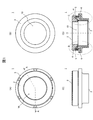
- FIG. 1A, FIG. 1B, and FIG. 1C are a front view, a rear view, and a side view of a plain bearing 1 according to an embodiment of the present invention
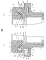
- FIG. FIG. 2 is a cross-sectional view taken along the line AA of the plain bearing 1 shown in FIG. 2A is an enlarged view of a portion B of the plain bearing 1 shown in FIG. 1D
- FIG. 2B is an enlarged view of a portion C of the plain bearing 1 shown in FIG. 3A, 3B, and 3C are a front view, a rear view, and a side view of the upper case 2
- FIG. 3D is an upper case shown in FIG. FIG.
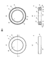
- FIG. 4 (A), 4 (B) and 4 (C) are a front view, a rear view and a side view of the lower case 3, and FIG. 4 (D) is a lower case shown in FIG. 4 (A).
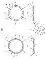
- 3 is a sectional view taken along line EE of FIG. 5A, 5B, and 5C are a front view, a back surface, and a side view of the center plate 4, and FIG. 5D is a center plate 4 shown in FIG. 5A.
- FIG. 5 (E) is an enlarged view of the G portion of the center plate 4 shown in FIG. 5 (A).
- 6 (A) and 6 (B) are diagrams for explaining a modified example of the sliding bearing 1, and correspond to FIGS. 2 (A) and 2 (B).
- FIG. 1A, 1B, and 1C are a front view, a rear view, and a side view of the plain bearing 1 according to the present embodiment
- FIG. FIG. 2 is a cross-sectional view taken along the line AA of the plain bearing 1 shown in FIG. 2A is an enlarged view of a portion B of the plain bearing 1 shown in FIG. 1D
- FIG. 2B is an enlarged view of a portion C of the plain bearing 1 shown in FIG. 1D. is there.
- the sliding bearing 1 includes a housing hole 10 for housing a strut assembly (not shown) of a strut suspension, and allows the strut assembly housed in the housing hole 10 to rotate. Supports the load applied to the strut suspension.
- the plain bearing 1 includes an upper case 2, a lower case 3 that is rotatably combined with the upper case 2, and forms an annular space 5 between the upper case 2 and the annular space 5.
- An annular center plate 4 arranged and a lubricating grease (not shown) filled in the annular space 5 are provided.
- the upper case 2 is formed of a thermoplastic resin having excellent sliding characteristics such as a polyacetal resin impregnated with a lubricating oil if necessary, and an upper mount (not shown) in a state where a strut assembly of a strut suspension is inserted. Attached to.
- FIG. 3A, 3B, and 3C are a front view, a rear view, and a side view of the upper case 2, and FIG. 3D is an upper case shown in FIG. FIG.
- the upper case 2 is formed on an annular upper case main body 21 having an insertion hole 20 for inserting a strut assembly, and an upper surface 22 of the upper case main body 21, and the sliding bearing 1 is attached to the upper mount.
- an annular groove 25 is formed on the lower surface 24 of the upper case body 21 and is rotatably combined with the lower case 3 so as to form the annular space 5
- the lower surface 23 side is opened and the upper surface 22 side is closed.
- an annular groove 25 is formed on the lower surface 24 of the upper case body 21 and is rotatably combined with the lower case 3 so as to form the annular space 5
- the lower surface 23 side is opened and the upper surface 22 side is closed.
- an annular groove 25 is formed on the lower surface 24 of the upper case body 21 and is rotatably combined with the
- the groove bottom 26 of the annular groove 25 is formed in a conical surface with the upper surface 22 side of the upper case body 21 as the bottom surface and the lower surface 23 side as the top portion, with the axis O of the insertion hole 20 as the center line,
- the groove bottom 26 is formed with a load transmission surface 27 that slides on a bearing surface 42 described later of the center plate 4.
- annular convex portion 28 protruding from the groove bottom 26 toward the lower surface 23 side of the upper case main body 21 is formed on the outer peripheral edge side of the load transmitting surface 27.
- the annular projection 28 surrounds the center plate 4 disposed in the annular groove 25, and when a load is applied to the strut suspension, the lubricating grease supplied onto the bearing surface 42 of the center plate 4 is centered. It is prevented from being pushed radially outward from the bearing surface 42 of the plate 4.
- the lower case 3 is an insert-molded product in which a steel plate 6 as a reinforcing material is embedded in a resin molded body using a thermoplastic resin such as a polyamide resin, and the strut in a state in which a strut assembly of a strut suspension is inserted.
- a coil spring (not shown) of the suspension is supported.
- FIG. 4 (A), 4 (B) and 4 (C) are a front view, a rear view and a side view of the lower case 3, and FIG. 4 (D) is a lower case shown in FIG. 4 (A).
- 3 is a sectional view taken along line EE of FIG.
- the lower case 3 is formed on a cylindrical lower case main body 31 having an insertion hole 30 for inserting a strut assembly, and an upper end portion 38 side of the lower case main body 31.
- An upper case of the upper case 2 is formed when the lower case 3 is rotatably combined with the upper case 2 and is formed on a flange portion 36 projecting radially outward from the outer peripheral surface 35 and the upper surface 32 of the flange portion 36.
- An annular protrusion 33 protruding toward the upper case 2 that is inserted into an annular groove 25 formed in the lower surface 23 of the main body 21 to form the annular space 5, and an elastic body such as urethane resin attached to the protrusion 33
- a dust seal 34 made of
- An upper spring seat (not shown), which is a spring seat at the upper end of a coil spring (not shown) of the strut suspension, is attached to the lower surface 360 of the flange portion 36 in a state where the strut assembly of the strut suspension is inserted.
- a mounting surface 331 for mounting the center plate 4 is formed on the upper surface 330 of the annular convex portion 33.
- the mounting surface 331 is a conical surface having the upper end 38 side of the lower case body 31 as the bottom surface and the lower surface 37 side as the top portion, with the axis O of the insertion hole 30 as the center line. Is formed.
- the shape of the mounting surface 331 may be any shape that matches the shape of the center plate 4 and can mount the center plate 4.
- a detent 332 for preventing rotation of the center plate 4 placed on the placement surface 331 is formed in an annular shape on the outer peripheral side of the placement surface 331.
- the rotation stopper 332 is configured by alternately arranging flat portions 3321 and convex portions 3320 protruding from the flat portion 3321 toward the upper case 2 side.
- the dust seal 34 is for preventing foreign matters such as dust from entering the annular space 5, and as shown in FIGS. 2 (A) and 2 (B), the convex portion 33 of the lower case 3 is formed as an upper portion.
- a lip 340 that closes the gap between the outer peripheral surface 333 of the convex portion 33 and the outer peripheral side inner wall 250 of the annular groove 25 when inserted into the annular groove 25 formed in the lower surface 24 of the upper case body 21 of the case 2;
- a lip 341 that closes the gap between the inner peripheral surface 334 of the portion 33 and the inner peripheral side inner wall 251 of the annular groove 25 is provided.
- the center plate 4 is formed of a thermoplastic resin having excellent sliding characteristics such as a polyolefin resin impregnated with a lubricating oil if necessary.
- the center plate 4 is fixed to the mounting surface 331 of the annular convex portion 33 formed on the upper surface 32 of the flange portion 36 of the lower case 3 and formed on the lower surface 23 of the upper case body 21 of the upper case 2. It slides with the load transmitting surface 27 of the annular groove 24. Thereby, it functions as a bearing body that realizes free rotation between the upper case 2 and the lower case 3.
- FIG. 5A, 5B, and 5C are a front view, a back surface, and a side view of the center plate 4, and FIG. 5D is a center plate 4 shown in FIG. 5A.
- FIG. 5 (E) is an enlarged view of the G portion of the center plate 4 shown in FIG. 5 (A).
- the center plate 4 includes a ring-shaped center plate body 40 into which a groove bottom 26 formed in a conical surface shape of the ring-shaped groove 25 of the upper case 2 is inserted, and a radial direction from the side surface 47 of the center plate body 40. And a plurality of convex detents 45 projecting outward.
- the upper surface 41 of the center plate body 40 is formed in a conical surface shape with the upper case 2 side as a bottom surface and the lower case 3 side as a top portion, with an axis O as a center line.
- a bearing surface 42 that slides on the load transmission surface 27 formed on the groove bottom 26 of the annular groove 25 of the case 2 is formed. Note that a burr may be provided on the inner diameter side of the center plate body 40.
- the rotation stopper 45 is formed so that the lower surface 42 of the center plate main body 40 comes into contact with the mounting surface 331 of the annular convex portion 33 formed on the upper surface 32 of the lower case main body 31 of the lower case 3.
- it When placed on the case 3, it is disposed on the flat portion 3321 of the rotation stopper 332 formed on the outer peripheral side of the placement surface 331, and is engaged with the convex portions 3320 located on both sides of the flat portion 3321.
- the center plate 4 is prevented from rotating relative to the lower case 3.
- the bearing surface 42 has a large number of recesses 46 that function as a lubricating grease reservoir. Accordingly, more lubricating grease is interposed between the bearing surface 42 of the center plate body 40 of the center plate 4 and the load transmission surface 27 formed on the groove bottom 26 of the annular groove 25 of the upper case 2. The sliding characteristics between the bearing surface 42 and the load transmission surface 27 can be improved.
- the center plate 4 is fixed to the mounting surface 331 of the annular convex portion 33 formed on the upper surface 32 of the flange portion 36 of the lower case 3, and the bearing surface 42 of the center plate 4 is the upper surface. It slides on a load transmission surface 27 formed on the groove bottom 26 of the annular groove 25 of the case 2.
- the upper case 2 and the lower case 3 are combined with each other via the center plate 4 so as to be rotatable.
- the bearing surface 42 of the center plate 4 and the load transmitting surface 27 of the upper case 2 are formed in a conical shape, and for this reason, the axial direction of the sliding bearing 1 shown in the thrust direction of the strut suspension (FIG. 1D).
- the slide bearing 1 allows the thrust and radial loads applied to the strut suspension to be applied to the strut suspension via the same load transmission surface 27 while allowing the strut assembly of the strut suspension inserted into the receiving hole 10 to rotate. And can be supported by the same bearing surface 42.
- the bearing surface 42 of the center plate 4 and the load transmission surface 27 of the upper case 2 are conical, so that the bearing surface 42 and the load transmission surface support the load applied to the strut suspension. In the state in which the two contact each other, there is no radial clearance between the bearing surface 42 and the load transmitting surface 27. Therefore, the radial play of the sliding bearing 1 can be prevented.
- the preferred inclination angle of the bearing surface 42 and the load transmission surface 27 (the angle formed by the plane perpendicular to the axis O) is 5 degrees to 20 degrees, and more preferably 10 degrees to 15 degrees.
- the inclination angle of the bearing surface 42 and the load transmission surface 27 is smaller than 5 degrees, the play between the two becomes large, and when the inclination angle is larger than 20 degrees, the sliding force between the both becomes large.
- the thrust slide bearing 1 has an annular space 5 formed by combining the upper case 2 and the lower case 3 with the groove bottom 26 of the annular groove 25 formed on the lower surface 24 of the upper case 2.
- An annular convex portion 28 that protrudes from the groove bottom 26 toward the lower case 3 side is provided so as to surround the outer peripheral side of the center plate 4 that is disposed on the center plate 4. The convex portion 28 can prevent the lubricating grease filled in the annular space 5 from being pushed radially outward from the bearing surface 42 of the center plate 4 when a load is applied to the strut suspension.
- the bearing surface 42 can be more reliably covered with the lubricating grease film, and the load applied in the thrust direction of the strut suspension can be supported for a longer period while allowing the strut assembly of the strut suspension to rotate smoothly. It becomes possible to do.
- the center plate 4 is mounted and fixed on the lower case 3, but the center plate 4 may be mounted so as to be rotatable with respect to the lower case 3. That is, like the upper surface 41 of the center plate 4, a bearing surface is also formed on the lower surface 43 of the center plate 4, and this bearing surface is formed on the upper surface 32 of the lower case body 31 of the lower case 3.
- the mounting surface 331 may be slidably contacted.
- a plurality of concave portions functioning as a lubricating grease reservoir may be formed on the bearing surface formed on the lower surface 43 of the center plate 4.
- the cross-sectional shapes of the bearing surface 42 and the load transmission surface 27 formed in a conical shape (the shape of the bearing surface 42 in the cross-section in the axis O direction of the center plate 4 and the axis O of the upper case 2).
- the shape of the load transmission surface 27 in the direction cross section is linear (see FIGS. 2A and 2B)
- the present invention is not limited to this.
- the angle of inclination of the bearing surface 42 and the load transmission surface 27 may be changed so that the cross-sectional shape thereof is a polygonal line formed by combining two or more straight lines.
- FIGS. 6 (A) and 6 (B) are diagrams for explaining a modified example of the sliding bearing 1, and correspond to FIGS. 2 (A) and 2 (B).
- the load transmission surface 27a is formed on a conical surface groove bottom 26a of an annular groove 25 provided on the lower surface 24 of the upper case body 21 of the upper case 2, and the cross-sectional shape thereof is the upper case.
- the main body 21 has an arc shape that is recessed toward the upper surface 22 side.
- the bearing surface 42a is formed on the conical surface 41a of the center plate 4, and its cross-sectional shape has a smaller diameter than the load transmission surface 27a and is an arc shape protruding toward the upper case 2 side. ing.
- the cross-sectional shapes of the bearing surface 42 and the load transmitting surface 27 formed in a conical surface are linear, so the bearing surface When the inclinations of 42 and the load transmission surface 27 coincide with each other, they are in surface contact.
- the line contact positions of the two vary. For this reason, the sliding characteristics of the sliding bearing 1 may not be stable.
- FIGS. 1 in the modification shown in FIGS.
- the cross-sectional shapes of the bearing surface 42a and the load transmission surface 27a formed in a conical surface are arc shapes (bearing surfaces) having different diameters. Since the diameter of 42a ⁇ the diameter of the load transmission surface 27a), the bearing surface 42a and the load transmission surface 27a are always in line contact with each other at a location where their tangents coincide with each other in the cross section. For this reason, it becomes possible to reduce the dispersion
- the bearing surface 42 of the center plate 4 and the load transmission surface 27 of the upper case 2 are respectively the shaft center O with the upper case 2 side as the bottom and the lower case 3 side as the top.
- it is formed in a conical surface shape as a center line, the present invention is not limited to this.
- the bearing surface 42 and the load transmission surface 27 may each be formed in a conical surface with the axis O as the center line, with the lower case 3 side as the bottom and the upper case 2 side as the top.
- the mounting surface 23 formed on the upper surface 22 of the upper case body 21 of the upper case 2 is perpendicular to the strut shaft of the strut suspension.
- the angle of the mounting surface 23 of the upper case 2 with respect to the strut shaft of the strut suspension may be appropriately determined according to the performance required for the vehicle.
- the mounting surface 23 of the upper case 2 may be inclined with respect to the strut shaft of the strut suspension.
- the upper spring seat that supports the upper end portion of the coil spring of the strut suspension is attached to the lower surface 360 of the flange portion 36 of the lower case 3.
- the lower surface 360 itself may function as an upper spring seat.
- the present invention is widely applied to a sliding bearing that supports a load to be supported, and particularly to a sliding bearing that supports a load applied to the shaft member while allowing the shaft member to rotate in various mechanisms including a strut suspension. Is possible.
Abstract
Provided is a sliding bearing wherein radial play is prevented.
A sliding bearing (1) comprises: an upper case (2) mounted to an upper support for mounting the strut assembly of a strut type suspension to a vehicle body; a lower case (3) which is mounted to an upper spring seat for supporting the upper end of the coil spring of the strut type suspension, is combined with the upper case (2) so that the upper case (2) and the lower case (3) can pivot relative to each other, and forms an annular space (5) between the upper case (2) and the lower case (3); and an annular center plate (4) disposed in the annular space (5) and enabling the upper case (2) and the lower case (3) to pivot relative to each other. The center plate (4) has a circular conical surface-shaped bearing surface (41). The upper case (2) has a circular conical surface-shaped load transmission surface (27) sliding on the bearing surface (42) of the center plate (4).
Description
本発明は、支持対象の荷重を支持する滑り軸受に関し、特に、軸部材の回動を許容しつつ、軸部材に加わる荷重を支持する滑り軸受に関する。
The present invention relates to a sliding bearing that supports a load to be supported, and particularly to a sliding bearing that supports a load applied to a shaft member while allowing the shaft member to rotate.
自動車の前輪に用いられるストラット式サスペンション(マクファーソンストラット)は、ピストンロッドおよび油圧式ショックアブソーバを備えたストラットアッセンブリに、コイルスプリングを組み合わせた構造を有しており、ステアリング操作によってストラットアッセンブリがコイルスプリングと共に回動する。このため、ストラットアッセンブリの円滑な回動を許容するべく、通常、車体へのストラットアッセンブリの取付機構であるアッパーマウントとコイルスプリング上端部のばね座であるアッパースプリングシートとの間に、軸受が配置されている。
A strut suspension (MacPherson strut) used for the front wheels of automobiles has a structure in which a coil spring is combined with a strut assembly having a piston rod and a hydraulic shock absorber. Rotate. For this reason, in order to allow smooth rotation of the strut assembly, a bearing is usually disposed between the upper mount, which is a mechanism for attaching the strut assembly to the vehicle body, and the upper spring seat, which is a spring seat at the upper end of the coil spring. Has been.
例えば、特許文献1には、ストラット式サスペンション用の軸受として、合成樹脂製の滑り軸受が開示されている。この滑り軸受は、アッパーマウント側に取り付けられる合成樹脂製のアッパーケースと、アッパースプリングシート側に取り付けられ、アッパーケースに回動自在に組み合わされる合成樹脂製のロワーケースと、アッパーケースおよびロワーケースを組み合わせることにより形成される環状空間に配置され、アッパーケースおよびロワーケース間の円滑な回動を実現する合成樹脂製の環状のセンタープレートと、を備えている。
For example, Patent Document 1 discloses a sliding bearing made of synthetic resin as a bearing for a strut suspension. This plain bearing is composed of a synthetic resin upper case attached to the upper mount side, a synthetic resin lower case attached to the upper spring seat side and rotatably combined with the upper case, and the upper case and the lower case. And an annular center plate made of a synthetic resin, which is disposed in an annular space formed by combination and realizes smooth rotation between the upper case and the lower case.
ここで、センタープレートは、表面にスラスト軸受面が形成された環部と、内周面にラジアル軸受面が形成され、環部の裏面の内周縁部に連結する円筒部と、を備えた断面L字形状のリング部材である。また、アッパーケースは、センタープレートの環部の表面に形成されたスラスト軸受面と摺動する環状のスラスト荷重伝達面と、センタープレートの円筒部に挿入され、この円筒部の内周面に形成されたラジアル軸受面と摺動する円筒状のラジアル荷重伝達面と、を有する。
Here, the center plate includes a ring portion having a thrust bearing surface formed on the surface, and a cylindrical portion having a radial bearing surface formed on the inner peripheral surface and connected to the inner peripheral edge portion of the back surface of the ring portion. It is an L-shaped ring member. The upper case is inserted into the thrust bearing surface formed on the surface of the ring portion of the center plate and slides on the annular thrust load transmission surface, and the cylindrical portion of the center plate, and is formed on the inner peripheral surface of the cylindrical portion. And a radial radial load transmission surface that slides and a cylindrical radial load transmission surface.
上記構成の滑り軸受は、ストラット式サスペンションに加わるスラスト方向の荷重を、アッパーケースのスラスト荷重伝達面を介して、センタープレートの環部の表面に形成されたスラスト軸受面で支持する一方、ストラット式サスペンションに加わるラジアル方向の荷重を、アッパーケースのラジアル荷重伝達面を介して、センタープレートの円筒部の内周面に形成されたラジアル軸受面で支持する。
The sliding bearing configured as described above supports the thrust load applied to the strut suspension by the thrust bearing surface formed on the surface of the ring portion of the center plate via the thrust load transmission surface of the upper case, while the strut bearing A radial load applied to the suspension is supported by a radial bearing surface formed on the inner peripheral surface of the cylindrical portion of the center plate via the radial load transmission surface of the upper case.
特許文献1に記載の滑り軸受において、アッパーケース、ロワーケース、およびセンタープレートには、これらの部品を確実に組み合わせられるようにするための寸法公差が設定されている。このため、これらの部品を組み合わせて滑り軸受を作製した場合、アッパーケースのラジアル荷重伝達面と、センタープレートの円筒部の内周面に形成されたラジアル軸受面との間にクリアランスが生じる。したがって、ストラット式サスペンションにこの滑り軸受を組み込んだ場合、滑り軸受にラジアル方向のガタツキが発生して、ステアリング操作に不快感を与える可能性がある。
In the plain bearing described in Patent Document 1, the upper case, the lower case, and the center plate are set with dimensional tolerances for ensuring that these components can be combined. For this reason, when a sliding bearing is produced by combining these components, a clearance is generated between the radial load transmission surface of the upper case and the radial bearing surface formed on the inner peripheral surface of the cylindrical portion of the center plate. Therefore, when this sliding bearing is incorporated in a strut suspension, radial sliding may occur in the sliding bearing, which may cause uncomfortable steering operation.
本発明は、上記事情に鑑みてなされたものであり、その目的は、ラジアル方向のガタツキを防止することができる滑り軸受を提供することにある。
The present invention has been made in view of the above circumstances, and an object of the present invention is to provide a sliding bearing capable of preventing radial play.
上記課題を解決するために、本発明の滑り軸受では、環状のセンタープレートの軸受面と、アッパーケースあるいはロワーケースに形成され、センタープレートの軸受面と摺動する荷重伝達面と、を円錐面状とし、これにより、アッパーケースに加わるスラスト方向およびラジアル方向の荷重を、同一の荷重伝達面を介して、同一の軸受面で支持するようにした。
In order to solve the above problems, in the sliding bearing of the present invention, a conical surface includes a bearing surface of an annular center plate and a load transmission surface formed on the upper case or the lower case and sliding with the bearing surface of the center plate. Thus, the thrust and radial loads applied to the upper case are supported by the same bearing surface via the same load transmission surface.
例えば、本発明は、支持対象の荷重を支持する滑り軸受であって、
前記支持対象の荷重を受けるアッパーケースと、
前記アッパーケースに回動自在に組み合わされて、当該アッパーケースとの間に環状空間を形成するロワーケースと、
前記環状空間に配置され、前記アッパーケースおよび前記ロワーケース間の回動を実現する環状のセンタープレートと、を備え、
前記センタープレートは、円錐面状の軸受面を有し、
前記アッパーケースあるいは前記ロワーケースは、
前記センタープレートの軸受面と摺動する円錐面状の荷重伝達面を有する。 For example, the present invention is a sliding bearing for supporting a load to be supported,
An upper case that receives the load of the support object;
A lower case that is rotatably combined with the upper case to form an annular space with the upper case;
An annular center plate that is disposed in the annular space and realizes rotation between the upper case and the lower case,
The center plate has a conical bearing surface,
The upper case or the lower case is
It has a conical load transmitting surface that slides with the bearing surface of the center plate.
ここで、前記滑り軸受は、軸部材の回動を許容しつつ、当該軸部材に加わる前記支持対象の荷重を支持するものであり、
前記アッパーケースは、前記軸部材が挿入された状態で当該軸部材の前記支持対象への取付機構に取り付けられ、
前記ロワーケースは、前記軸部材が挿入された状態で前記軸部材に組み合わせられたコイルスプリングを支持し、
前記センタープレートは、前記軸部材が挿入された状態で前記環状空間に配置されるものでもよい。 Here, the sliding bearing supports the load of the support target applied to the shaft member while allowing the shaft member to rotate.
The upper case is attached to a mechanism for attaching the shaft member to the support target in a state where the shaft member is inserted,
The lower case supports a coil spring combined with the shaft member in a state where the shaft member is inserted,
The center plate may be disposed in the annular space with the shaft member inserted.
本発明では、センタープレートの軸受面およびアッパーケースあるいはロワーケースの荷重伝達面を円錐面状とし、アッパーケースに加わるスラスト方向およびラジアル方向の荷重を、同一の荷重伝達面を介して、同一の軸受面で支持している。このため、アッパーケースに加わるスラスト方向およびラジアル方向の荷重を支持するべく、軸受面および荷重伝達面が接触した状態では、軸受面と荷重伝達面との間にラジアル方向のクリアランスが発生しない。したがって、滑り軸受のラジアル方向のガタツキを防止することができる。
In the present invention, the bearing surface of the center plate and the load transmission surface of the upper case or the lower case are conical, and the thrust and radial loads applied to the upper case are transmitted to the same bearing via the same load transmission surface. It is supported by the surface. Therefore, no radial clearance is generated between the bearing surface and the load transmission surface when the bearing surface and the load transmission surface are in contact with each other so as to support the thrust and radial loads applied to the upper case. Therefore, radial play of the slide bearing can be prevented.
以下、本発明の一実施の形態について説明する。
Hereinafter, an embodiment of the present invention will be described.
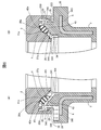
図1(A)、図1(B)および図1(C)は、本実施の形態に係る滑り軸受1の正面図、背面図および側面図であり、図1(D)は、図1(A)に示す滑り軸受1のA-A断面図である。また、図2(A)は、図1(D)に示す滑り軸受1のB部拡大図であり、図2(B)は、図1(D)に示す滑り軸受1のC部拡大図である。
1A, 1B, and 1C are a front view, a rear view, and a side view of the plain bearing 1 according to the present embodiment, and FIG. FIG. 2 is a cross-sectional view taken along the line AA of the plain bearing 1 shown in FIG. 2A is an enlarged view of a portion B of the plain bearing 1 shown in FIG. 1D, and FIG. 2B is an enlarged view of a portion C of the plain bearing 1 shown in FIG. 1D. is there.
本実施の形態に係る滑り軸受1は、ストラット式サスペンションのストラットアッセンブリ(不図示)を収容するための収容孔10を備え、この収容孔10に収容されたストラットアッセンブリの回動を許容しつつ、ストラット式サスペンションに加わる荷重を支持する。図示するように、滑り軸受1は、アッパーケース2と、アッパーケース2と回動自在に組み合わされて、アッパーケース2との間に環状空間5を形成するロワーケース3と、この環状空間5に配置された環状のセンタープレート4と、図示していないが、環状空間5に充填された潤滑グリースと、を備えている。
The sliding bearing 1 according to the present embodiment includes a housing hole 10 for housing a strut assembly (not shown) of a strut suspension, and allows the strut assembly housed in the housing hole 10 to rotate. Supports the load applied to the strut suspension. As shown in the figure, the plain bearing 1 includes an upper case 2, a lower case 3 that is rotatably combined with the upper case 2, and forms an annular space 5 between the upper case 2 and the annular space 5. An annular center plate 4 arranged and a lubricating grease (not shown) filled in the annular space 5 are provided.
アッパーケース2は、必要に応じて潤滑油が含浸されたポリアセタール樹脂等の摺動特性に優れた熱可塑性樹脂で形成され、ストラット式サスペンションのストラットアッセンブリが挿入された状態でアッパーマウント(不図示)に取り付けられる。
The upper case 2 is formed of a thermoplastic resin having excellent sliding characteristics such as a polyacetal resin impregnated with a lubricating oil if necessary, and an upper mount (not shown) in a state where a strut assembly of a strut suspension is inserted. Attached to.
図3(A)、図3(B)および図3(C)は、アッパーケース2の正面図、背面図および側面図であり、図3(D)は、図3(A)に示すアッパーケース2のD-D断面図である。
3A, 3B, and 3C are a front view, a rear view, and a side view of the upper case 2, and FIG. 3D is an upper case shown in FIG. FIG.
図示するように、アッパーケース2は、ストラットアッセンブリを挿入するための挿入孔20を備えた環状のアッパーケース本体21と、アッパーケース本体21の上面22に形成され、滑り軸受1をアッパーマウントに取り付けるための取付面23と、アッパーケース本体21の下面24に形成され、ロワーケース3と回動自在に組み合わされることにより環状空間5を形成するための、下面23側が開口し、上面22側が閉塞した環状溝25と、を備える。
As shown in the figure, the upper case 2 is formed on an annular upper case main body 21 having an insertion hole 20 for inserting a strut assembly, and an upper surface 22 of the upper case main body 21, and the sliding bearing 1 is attached to the upper mount. Is formed on the lower surface 24 of the upper case body 21 and is rotatably combined with the lower case 3 so as to form the annular space 5, the lower surface 23 side is opened and the upper surface 22 side is closed. And an annular groove 25.
環状溝25の溝底26は、アッパーケース本体21の上面22側を底面とし、下面23側を頂部とする、挿入孔20の軸心Oを中心線とした円錐面状に形成されており、この溝底26には、センタープレート4の後述の軸受面42と摺動する荷重伝達面27が形成されている。
The groove bottom 26 of the annular groove 25 is formed in a conical surface with the upper surface 22 side of the upper case body 21 as the bottom surface and the lower surface 23 side as the top portion, with the axis O of the insertion hole 20 as the center line, The groove bottom 26 is formed with a load transmission surface 27 that slides on a bearing surface 42 described later of the center plate 4.
また、環状溝25の溝底26において、荷重伝達面27の外周縁側には、溝底26からアッパーケース本体21の下面23側に突出した環状の凸部28が形成されている。この環状の凸部28は、環状溝25に配置されたセンタープレート4を囲んでおり、ストラット式サスペンションに荷重が加わった場合に、センタープレート4の軸受面42上に供給された潤滑グリースがセンタープレート4の軸受面42から径方向外向に押し出されるのを防止する。
Further, in the groove bottom 26 of the annular groove 25, an annular convex portion 28 protruding from the groove bottom 26 toward the lower surface 23 side of the upper case main body 21 is formed on the outer peripheral edge side of the load transmitting surface 27. The annular projection 28 surrounds the center plate 4 disposed in the annular groove 25, and when a load is applied to the strut suspension, the lubricating grease supplied onto the bearing surface 42 of the center plate 4 is centered. It is prevented from being pushed radially outward from the bearing surface 42 of the plate 4.
ロワーケース3は、ポリアミド樹脂等の熱可塑性樹脂を用いた樹脂成形体に、補強材であるスチールプレート6が埋め込まれたインサート成形品であり、ストラット式サスペンションのストラットアッセンブリが挿入された状態でストラット式サスペンションのコイルスプリング(不図示)の上端部を支持する。
The lower case 3 is an insert-molded product in which a steel plate 6 as a reinforcing material is embedded in a resin molded body using a thermoplastic resin such as a polyamide resin, and the strut in a state in which a strut assembly of a strut suspension is inserted. The upper end of a coil spring (not shown) of the suspension is supported.
図4(A)、図4(B)および図4(C)は、ロワーケース3の正面図、背面図および側面図であり、図4(D)は、図4(A)に示すロワーケース3のE-E断面図である。
4 (A), 4 (B) and 4 (C) are a front view, a rear view and a side view of the lower case 3, and FIG. 4 (D) is a lower case shown in FIG. 4 (A). 3 is a sectional view taken along line EE of FIG.
図示するように、ロワーケース3は、ストラットアッセンブリを挿入するための挿入孔30を備えた筒状のロワーケース本体31と、ロワーケース本体31の上端部38側に形成され、ロワーケース本体31の外周面35から径方向外方へ張り出したフランジ部36と、フランジ部36の上面32に形成され、ロワーケース3がアッパーケース2と回動自在に組み合わされた場合に、アッパーケース2のアッパーケース本体21の下面23に形成された環状溝25に挿入されて環状空間5を形成する、アッパーケース2側に突出した環状の凸部33と、凸部33に取り付けられ、ウレタン樹脂等の弾性体からなるダストシール34と、を備えている。
As shown in the figure, the lower case 3 is formed on a cylindrical lower case main body 31 having an insertion hole 30 for inserting a strut assembly, and an upper end portion 38 side of the lower case main body 31. An upper case of the upper case 2 is formed when the lower case 3 is rotatably combined with the upper case 2 and is formed on a flange portion 36 projecting radially outward from the outer peripheral surface 35 and the upper surface 32 of the flange portion 36. An annular protrusion 33 protruding toward the upper case 2 that is inserted into an annular groove 25 formed in the lower surface 23 of the main body 21 to form the annular space 5, and an elastic body such as urethane resin attached to the protrusion 33 A dust seal 34 made of
フランジ部36の下面360には、ストラット型サスペンションのストラットアッセンブリが挿入された状態でストラット型サスペンションのコイルスプリング(不図示)上端部のばね座であるアッパースプリングシート(不図示)が取り付けられる。
An upper spring seat (not shown), which is a spring seat at the upper end of a coil spring (not shown) of the strut suspension, is attached to the lower surface 360 of the flange portion 36 in a state where the strut assembly of the strut suspension is inserted.
環状の凸部33の上面330には、センタープレート4を載置するための載置面331が形成されている。なお、本実施の形態では、載置面331を、ロワーケース本体31の上端部38側を底面とし、下面37側を頂部とする、挿入孔30の軸心Oを中心線とした円錐面状に形成している。しかし、載置面331の形状は、センタープレート4の形状に合わせた、センタープレート4を載置可能な形状であればよい。
A mounting surface 331 for mounting the center plate 4 is formed on the upper surface 330 of the annular convex portion 33. In the present embodiment, the mounting surface 331 is a conical surface having the upper end 38 side of the lower case body 31 as the bottom surface and the lower surface 37 side as the top portion, with the axis O of the insertion hole 30 as the center line. Is formed. However, the shape of the mounting surface 331 may be any shape that matches the shape of the center plate 4 and can mount the center plate 4.
載置面331の外周側には、載置面331に載置されたセンタープレート4の回転を防止するための回り止め332が環状に形成されている。この回り止め332は、平坦部3321と、平坦部3321からアッパーケース2側に突出した凸部3320とが、交互に配置されて構成される。
A detent 332 for preventing rotation of the center plate 4 placed on the placement surface 331 is formed in an annular shape on the outer peripheral side of the placement surface 331. The rotation stopper 332 is configured by alternately arranging flat portions 3321 and convex portions 3320 protruding from the flat portion 3321 toward the upper case 2 side.
ダストシール34は、塵埃等の異物が環状空間5に侵入するのを防止するためのものであり、図2(A)および図2(B)に示すように、ロワーケース3の凸部33がアッパーケース2のアッパーケース本体21の下面24に形成された環状溝25に挿入された場合に、凸部33の外周面333と環状溝25の外周側内壁250との隙間を塞ぐリップ340、および凸部33の内周面334と環状溝25の内周側内壁251との隙間を塞ぐリップ341を備えている。
The dust seal 34 is for preventing foreign matters such as dust from entering the annular space 5, and as shown in FIGS. 2 (A) and 2 (B), the convex portion 33 of the lower case 3 is formed as an upper portion. A lip 340 that closes the gap between the outer peripheral surface 333 of the convex portion 33 and the outer peripheral side inner wall 250 of the annular groove 25 when inserted into the annular groove 25 formed in the lower surface 24 of the upper case body 21 of the case 2; A lip 341 that closes the gap between the inner peripheral surface 334 of the portion 33 and the inner peripheral side inner wall 251 of the annular groove 25 is provided.
センタープレート4は、必要に応じて潤滑油が含浸されたポリオレフィン樹脂等の摺動特性に優れた熱可塑性樹脂で形成される。また、センタープレート4は、ロワーケース3のフランジ部36の上面32に形成された環状の凸部33の載置面331に固定され、アッパーケース2のアッパーケース本体21の下面23に形成された環状溝24の荷重伝達面27と摺動する。これにより、アッパーケース2およびロワーケース3間の自在な回動を実現する軸受体として機能する。
The center plate 4 is formed of a thermoplastic resin having excellent sliding characteristics such as a polyolefin resin impregnated with a lubricating oil if necessary. The center plate 4 is fixed to the mounting surface 331 of the annular convex portion 33 formed on the upper surface 32 of the flange portion 36 of the lower case 3 and formed on the lower surface 23 of the upper case body 21 of the upper case 2. It slides with the load transmitting surface 27 of the annular groove 24. Thereby, it functions as a bearing body that realizes free rotation between the upper case 2 and the lower case 3.
図5(A)、図5(B)および図5(C)は、センタープレート4の正面図、背面および側面図であり、図5(D)は、図5(A)に示すセンタープレート4のF-F断面図であり、図5(E)は、図5(A)に示すセンタープレート4のG部拡大図である。
5A, 5B, and 5C are a front view, a back surface, and a side view of the center plate 4, and FIG. 5D is a center plate 4 shown in FIG. 5A. FIG. 5 (E) is an enlarged view of the G portion of the center plate 4 shown in FIG. 5 (A).
図示するように、センタープレート4は、アッパーケース2の環状溝25の円錐面状に形成された溝底26が挿入される環状のセンタープレート本体40と、センタープレート本体40の側面47から径方向外方に張り出した複数の凸状の回り止め45と、を備えている。
As shown in the drawing, the center plate 4 includes a ring-shaped center plate body 40 into which a groove bottom 26 formed in a conical surface shape of the ring-shaped groove 25 of the upper case 2 is inserted, and a radial direction from the side surface 47 of the center plate body 40. And a plurality of convex detents 45 projecting outward.
センタープレート本体40の上面41は、アッパーケース2側を底面とし、ロワーケース3側を頂部とする、軸心Oを中心線とした円錐面状に形成されており、この上面41には、アッパーケース2の環状溝25の溝底26に形成された荷重伝達面27と摺動する軸受面42が形成されている。なお、センタープレート本体40の内径側にかえりを設けてもよい。
The upper surface 41 of the center plate body 40 is formed in a conical surface shape with the upper case 2 side as a bottom surface and the lower case 3 side as a top portion, with an axis O as a center line. A bearing surface 42 that slides on the load transmission surface 27 formed on the groove bottom 26 of the annular groove 25 of the case 2 is formed. Note that a burr may be provided on the inner diameter side of the center plate body 40.
回り止め45は、センタープレート本体40の下面42がロワーケース3のロワーケース本体31の上面32に形成された環状の凸部33の載置面331と接触するようにして、センタープレート4がロワーケース3上に載置された場合に、この載置面331の外周側に形成された回り止め332の平坦部3321上に配置されて、この平坦部3321の両側に位置する凸部3320と係合することにより、センタープレート4がロワーケース3に対して相対的に回転するのを防止する。
The rotation stopper 45 is formed so that the lower surface 42 of the center plate main body 40 comes into contact with the mounting surface 331 of the annular convex portion 33 formed on the upper surface 32 of the lower case main body 31 of the lower case 3. When placed on the case 3, it is disposed on the flat portion 3321 of the rotation stopper 332 formed on the outer peripheral side of the placement surface 331, and is engaged with the convex portions 3320 located on both sides of the flat portion 3321. By combining, the center plate 4 is prevented from rotating relative to the lower case 3.
軸受面42には、潤滑グリース溜めとして機能する多数の凹部46が形成されている。これにより、センタープレート4のセンタープレート本体40の軸受面42と、アッパーケース2の環状溝25の溝底26に形成された荷重伝達面27との間に、より多くの潤滑グリースを介在させることが可能となり、軸受面42および荷重伝達面27間の摺動特性を向上させることができる。
The bearing surface 42 has a large number of recesses 46 that function as a lubricating grease reservoir. Accordingly, more lubricating grease is interposed between the bearing surface 42 of the center plate body 40 of the center plate 4 and the load transmission surface 27 formed on the groove bottom 26 of the annular groove 25 of the upper case 2. The sliding characteristics between the bearing surface 42 and the load transmission surface 27 can be improved.
上記構成を有する滑り軸受1において、センタープレート4はロワーケース3のフランジ部36の上面32に形成された環状の凸部33の載置面331に固定され、センタープレート4の軸受面42がアッパーケース2の環状溝25の溝底26に形成された荷重伝達面27と摺動する。これにより、アッパーケース2およびロワーケース3は、センタープレート4を介して互いに回動自在に組み合わされる。また、センタープレート4の軸受面42およびアッパーケース2の荷重伝達面27は円錐面状に形成されており、このため、ストラット式サスペンションのスラスト方向(図1(D)に示す滑り軸受1の軸心O方向)およびラジアル方向に対して斜めに配置される。したがって、滑り軸受1は、収容孔10に挿入されたストラット式サスペンションのストラットアッセンブリの回動を許容しつつ、ストラット式サスペンションに加わるスラスト方向およびラジアル方向の荷重を、同一の荷重伝達面27を介して、同一の軸受面42で支持することができる。
In the slide bearing 1 having the above configuration, the center plate 4 is fixed to the mounting surface 331 of the annular convex portion 33 formed on the upper surface 32 of the flange portion 36 of the lower case 3, and the bearing surface 42 of the center plate 4 is the upper surface. It slides on a load transmission surface 27 formed on the groove bottom 26 of the annular groove 25 of the case 2. Thereby, the upper case 2 and the lower case 3 are combined with each other via the center plate 4 so as to be rotatable. Further, the bearing surface 42 of the center plate 4 and the load transmitting surface 27 of the upper case 2 are formed in a conical shape, and for this reason, the axial direction of the sliding bearing 1 shown in the thrust direction of the strut suspension (FIG. 1D). (Center O direction) and the radial direction. Therefore, the slide bearing 1 allows the thrust and radial loads applied to the strut suspension to be applied to the strut suspension via the same load transmission surface 27 while allowing the strut assembly of the strut suspension inserted into the receiving hole 10 to rotate. And can be supported by the same bearing surface 42.
また、本実施の形態では、センタープレート4の軸受面42およびアッパーケース2の荷重伝達面27を円錐面状としているので、ストラット式サスペンションに加わる荷重を支持するべく、軸受面42および荷重伝達面27が互いに接触した状態では、軸受面42と荷重伝達面27との間にラジアル方向のクリアランスが発生しない。したがって、滑り軸受1のラジアル方向のガタツキを防止することができる。
In the present embodiment, the bearing surface 42 of the center plate 4 and the load transmission surface 27 of the upper case 2 are conical, so that the bearing surface 42 and the load transmission surface support the load applied to the strut suspension. In the state in which the two contact each other, there is no radial clearance between the bearing surface 42 and the load transmitting surface 27. Therefore, the radial play of the sliding bearing 1 can be prevented.
なお、軸受面42および荷重伝達面27の好ましい傾斜角度(軸心Oと垂直な平面とのなす角)は、5度~20度であり、より好ましくは10度~15度である。軸受面42および荷重伝達面27の傾斜角度が5度より小さくなると、両者間のガタが大きくなり、20度より大きくなると、両者間の摺動力が大きくなる。
It should be noted that the preferred inclination angle of the bearing surface 42 and the load transmission surface 27 (the angle formed by the plane perpendicular to the axis O) is 5 degrees to 20 degrees, and more preferably 10 degrees to 15 degrees. When the inclination angle of the bearing surface 42 and the load transmission surface 27 is smaller than 5 degrees, the play between the two becomes large, and when the inclination angle is larger than 20 degrees, the sliding force between the both becomes large.
また、本実施の形態では、センタープレート4の軸受面42に潤滑グリース溜めとして機能する凹部46を複数設けているので、軸受面42上により多くの潤滑グリースを保持することができる。このため、より長期に亘り、ストラット型サスペンションのストラットアッセンブリの円滑な回動を許容しつつ、ストラット型サスペンションのスラスト方向に加わる荷重を支持することが可能となる。
In the present embodiment, since a plurality of recesses 46 functioning as a lubricating grease reservoir are provided on the bearing surface 42 of the center plate 4, more lubricating grease can be held on the bearing surface 42. For this reason, it is possible to support the load applied in the thrust direction of the strut type suspension while allowing the strut assembly of the strut type suspension to rotate smoothly for a longer period of time.
また、本実施の形態に係るスラスト滑り軸受1は、アッパーケース2の下面24に形成された環状溝25の溝底26に、アッパーケース2およびロワーケース3を組み合わせることにより形成される環状空間5に配置されたセンタープレート4の外周側を囲むように溝底26からロワーケース3側に突出した環状の凸部28を設けている。この凸部28により、ストラット型サスペンションに荷重が加わった場合に、環状空間5に充填された潤滑グリースがセンタープレート4の軸受面42上から径方向外側に押し出されるのを防止することができ、したがって、軸受面42をより確実に潤滑グリース膜で覆うことができ、より長期に亘り、ストラット型サスペンションのストラットアッセンブリの円滑な回動を許容しつつ、ストラット型サスペンションのスラスト方向にかかる荷重を支持することが可能となる。
Further, the thrust slide bearing 1 according to the present embodiment has an annular space 5 formed by combining the upper case 2 and the lower case 3 with the groove bottom 26 of the annular groove 25 formed on the lower surface 24 of the upper case 2. An annular convex portion 28 that protrudes from the groove bottom 26 toward the lower case 3 side is provided so as to surround the outer peripheral side of the center plate 4 that is disposed on the center plate 4. The convex portion 28 can prevent the lubricating grease filled in the annular space 5 from being pushed radially outward from the bearing surface 42 of the center plate 4 when a load is applied to the strut suspension. Accordingly, the bearing surface 42 can be more reliably covered with the lubricating grease film, and the load applied in the thrust direction of the strut suspension can be supported for a longer period while allowing the strut assembly of the strut suspension to rotate smoothly. It becomes possible to do.
なお、本発明は、上記の実施の形態に限定されるものではなく、その要旨の範囲内で数々の変形は可能である。
It should be noted that the present invention is not limited to the above-described embodiment, and various modifications are possible within the scope of the gist.
例えば、上記の実施の形態では、センタープレート4をロワーケース3に載置し固定しているが、センタープレート4をロワーケース3に対して回動自在に載置してもよい。すなわち、センタープレート4の上面41と同様に、センタープレート4の下面43にも軸受面を形成し、この軸受面を、ロワーケース3のロワーケース本体31の上面32に形成された凸部33の載置面331と摺動可能に接触させてもよい。この場合、センタープレート4の上面41と同様、センタープレート4の下面43に形成された軸受面に潤滑グリース溜めとして機能する凹部を複数形成してもよい。
For example, in the above-described embodiment, the center plate 4 is mounted and fixed on the lower case 3, but the center plate 4 may be mounted so as to be rotatable with respect to the lower case 3. That is, like the upper surface 41 of the center plate 4, a bearing surface is also formed on the lower surface 43 of the center plate 4, and this bearing surface is formed on the upper surface 32 of the lower case body 31 of the lower case 3. The mounting surface 331 may be slidably contacted. In this case, similarly to the upper surface 41 of the center plate 4, a plurality of concave portions functioning as a lubricating grease reservoir may be formed on the bearing surface formed on the lower surface 43 of the center plate 4.
また、上記の実施の形態では、それぞれ円錐面状に形成された軸受面42および荷重伝達面27の断面形状(センタープレート4の軸O方向断面における軸受面42の形状およびアッパーケース2の軸O方向断面における荷重伝達面27の形状)を直線状にしているが(図2(A)および図2(B)参照)、本発明はこれに限定されない。例えば、軸受面42および荷重伝達面27の傾斜角度を変化させて、これらの断面形状を2以上の直線を組み合わせた折れ線状にしてもよい。あるいは、軸受面42および荷重伝達面27の断面形状を互いに径の異なる円弧状にしてもよい。
Further, in the above-described embodiment, the cross-sectional shapes of the bearing surface 42 and the load transmission surface 27 formed in a conical shape (the shape of the bearing surface 42 in the cross-section in the axis O direction of the center plate 4 and the axis O of the upper case 2). Although the shape of the load transmission surface 27 in the direction cross section is linear (see FIGS. 2A and 2B), the present invention is not limited to this. For example, the angle of inclination of the bearing surface 42 and the load transmission surface 27 may be changed so that the cross-sectional shape thereof is a polygonal line formed by combining two or more straight lines. Or you may make the cross-sectional shape of the bearing surface 42 and the load transmission surface 27 into circular arc shape from which a diameter mutually differs.
図6(A)および図6(B)は、滑り軸受1の変形例を説明するための図であり、図2(A)および図2(B)に相当する図である。
6 (A) and 6 (B) are diagrams for explaining a modified example of the sliding bearing 1, and correspond to FIGS. 2 (A) and 2 (B).
図示するように、荷重伝達面27aは、アッパーケース2のアッパーケース本体21の下面24に設けられた環状溝25の円錐面状の溝底26aに形成されており、その断面形状は、アッパーケース本体21の上面22側に窪んだ円弧状となっている。また、軸受面42aは、センタープレート4の円錐面状の上面41aに形成されており、その断面形状は、荷重伝達面27aより小さな径を有し、アッパーケース2側に突出した円弧状となっている。
As shown in the drawing, the load transmission surface 27a is formed on a conical surface groove bottom 26a of an annular groove 25 provided on the lower surface 24 of the upper case body 21 of the upper case 2, and the cross-sectional shape thereof is the upper case. The main body 21 has an arc shape that is recessed toward the upper surface 22 side. Further, the bearing surface 42a is formed on the conical surface 41a of the center plate 4, and its cross-sectional shape has a smaller diameter than the load transmission surface 27a and is an arc shape protruding toward the upper case 2 side. ing.
上記の実施の形態では、図2(A)および図2(B)に示すように、円錐面状に形成された軸受面42および荷重伝達面27の断面形状を直線状としているので、軸受面42および荷重伝達面27の傾きが一致する場合、両者は面接触となる。しかし、製造上等の問題から両者の傾きを一致させることは困難であり、実際には、両者の傾きが一致せず、したがって両者が線接触となる。ここで、両者の傾きがばらつくと、両者の線接触位置にばらつきが生じる。このため、滑り軸受1の摺動特性が安定しない可能性がある。これに対して、図6(A)および図6(B)に示す変形例では、円錐面状に形成された軸受面42aおよび荷重伝達面27aの断面形状を互いに径の異なる円弧状(軸受面42aの径<荷重伝達面27aの径)としているため、軸受面42aおよび荷重伝達面27aは、断面において、常に互いの接線が一致する箇所で線接触する。このため、両者の線接触位置のばらつきを減らして、滑り軸受1の摺動特性をより安定させることが可能となる。
In the above embodiment, as shown in FIGS. 2 (A) and 2 (B), the cross-sectional shapes of the bearing surface 42 and the load transmitting surface 27 formed in a conical surface are linear, so the bearing surface When the inclinations of 42 and the load transmission surface 27 coincide with each other, they are in surface contact. However, it is difficult to make the inclinations of the two coincide with each other due to problems in manufacturing and the like, and in fact, the inclinations of the two do not coincide with each other. Here, if the inclinations of the two vary, the line contact positions of the two vary. For this reason, the sliding characteristics of the sliding bearing 1 may not be stable. On the other hand, in the modification shown in FIGS. 6A and 6B, the cross-sectional shapes of the bearing surface 42a and the load transmission surface 27a formed in a conical surface are arc shapes (bearing surfaces) having different diameters. Since the diameter of 42a <the diameter of the load transmission surface 27a), the bearing surface 42a and the load transmission surface 27a are always in line contact with each other at a location where their tangents coincide with each other in the cross section. For this reason, it becomes possible to reduce the dispersion | variation in both line contact positions, and to stabilize the sliding characteristic of the sliding bearing 1 more.
また、上記の実施の形態では、センタープレート4の軸受面42およびアッパーケース2の荷重伝達面27を、それぞれ、アッパーケース2側を底面とし、ロワーケース3側を頂部とする、軸心Oを中心線とした円錐面状に形成しているが、本発明はこれに限定されない。軸受面42および荷重伝達面27を、それぞれ、ロワーケース3側を底面とし、アッパーケース2側を頂部とする、軸心Oを中心線とした円錐面状に形成してもよい。
Further, in the above-described embodiment, the bearing surface 42 of the center plate 4 and the load transmission surface 27 of the upper case 2 are respectively the shaft center O with the upper case 2 side as the bottom and the lower case 3 side as the top. Although it is formed in a conical surface shape as a center line, the present invention is not limited to this. The bearing surface 42 and the load transmission surface 27 may each be formed in a conical surface with the axis O as the center line, with the lower case 3 side as the bottom and the upper case 2 side as the top.
また、上記の実施の形態では、アッパーケース2のアッパーケース本体21の上面22に形成された取付面23を、ストラット式サスペンションのストラット軸に対して垂直としている。しかし、本発明はこれに限定されない。ストラット式サスペンションのストラット軸に対するアッパーケース2の取付面23の角度は、車両に要求される性能に応じて適宜決めればよい。例えば、アッパーケース2の取付面23をストラット式サスペンションのストラット軸に対して傾斜させてもよい。
In the above embodiment, the mounting surface 23 formed on the upper surface 22 of the upper case body 21 of the upper case 2 is perpendicular to the strut shaft of the strut suspension. However, the present invention is not limited to this. The angle of the mounting surface 23 of the upper case 2 with respect to the strut shaft of the strut suspension may be appropriately determined according to the performance required for the vehicle. For example, the mounting surface 23 of the upper case 2 may be inclined with respect to the strut shaft of the strut suspension.
また、上記の実施の形態では、ロワーケース3のフランジ部36の下面360に、ストラット型サスペンションのコイルスプリングの上端部を支持するアッパースプリングシートを取り付けているが、ロワーケース3のフランジ部36の下面360自体をアッパースプリングシートとして機能させてもよい。
In the above embodiment, the upper spring seat that supports the upper end portion of the coil spring of the strut suspension is attached to the lower surface 360 of the flange portion 36 of the lower case 3. The lower surface 360 itself may function as an upper spring seat.
本発明は、支持対象の荷重を支持する滑り軸受、特に、ストラット式サスペンションを含む様々な機構において、軸部材の回動を許容しつつ、この軸部材に加わる荷重を支持する滑り軸受に広く適用可能である。
INDUSTRIAL APPLICABILITY The present invention is widely applied to a sliding bearing that supports a load to be supported, and particularly to a sliding bearing that supports a load applied to the shaft member while allowing the shaft member to rotate in various mechanisms including a strut suspension. Is possible.
1:滑り軸受、 2:アッパーケース、 3:ロワーケース、 4:センタープレート、 5:環状空間、 6:スチールプレート、 10:滑り軸受1の収容孔、 20:アッパーケース2の挿入孔、 21:アッパーケース本体、 22:アッパーケース本体の上面、 23:アッパーケース本体21の取付面、 24:アッパーケース本体21の下面、 25:アッパーケース本体21の環状溝、 26、26a:環状溝25の溝底、 27、27a:荷重伝達面、 28:環状溝25の環状の凸部、 30:ロワーケース3の挿入孔、 31:ロワーケース本体、 32:ロワーケース本体31の上面、 33:ロワーケース本体31の環状の凸部、 34:ダストシール、 35:ロワーケース本体31の側面、 36:ロワーケース本体31のフランジ、 37:ロワーケース本体31の下面、 38:ロワーケース本体31の上端部、 40:センタープレート本体、 41、41a:センタープレート本体40の上面、 42、42a:軸受面、 43:センタープレート本体40の下面、 45:センタープレート本体40の回り止め、 46:軸受面42の凹部、 47:センタープレート本体40の側面、 250:環状溝25の外周側内壁、 251:環状溝25の内周側内壁、 330:環状の凸部33の上面、 331:ロワーケース本体31の載置面、 332:ロワーケース本体31の回り止め、 333:環状の凸部33の外周面、 334:環状の凸部33の内周面、 340、341:ダストシール34のリップ、 360:フランジ36の裏面、 3320:回り止め332の凸部、 3321:回り止め332の平坦部
1: sliding bearing, 2: upper case, 3: lower case, 4: center plate, 5: annular space, 6: steel plate, 10: receiving hole for sliding bearing 1, 20: insertion hole for upper case 2, 21: Upper case body, 22: upper surface of upper case body, 23: mounting surface of upper case body 21, 24: lower surface of upper case body 21, 25: annular groove of upper case body 21, 26, 26a: grooves of annular groove 25 Bottom, 27, 27a: load transmission surface, 28: annular convex portion of annular groove 25, 30: insertion hole of lower case 3, 31: lower case main body, 32: upper surface of lower case main body 31, 33: lower case main body 31 annular projections, 34: dust seal, 35: side surface of lower case body 31, 36: lower 37: lower surface of the lower case body 31, 38: upper end of the lower case body 31, 40: center plate body, 41, 41a: upper surface of the center plate body 40, 42, 42a: bearing surface, 43: lower surface of the center plate body 40, 45: rotation prevention of the center plate body 40, 46: recess of the bearing surface 42, 47: side surface of the center plate body 40, 250: inner wall on the outer peripheral side of the annular groove 25, 251: annular groove 25, the inner wall of the inner peripheral side, 330: the upper surface of the annular convex portion 33, 331: the mounting surface of the lower case main body 31, 332: the rotation prevention of the lower case main body 31, 333: the outer peripheral surface of the annular convex portion 33, 334 : Inner peripheral surface of annular convex portion 33, 340, 341: lip of dust seal 34, 360: flange 3 The back surface of, 3320: convex portion of the detent 332, 3321: the flat portion of the detent 332
Claims (5)
- 支持対象の荷重を支持する滑り軸受であって、
前記支持対象の荷重を受けるアッパーケースと、
前記アッパーケースに回動自在に組み合わされて、当該アッパーケースとの間に環状空間を形成するロワーケースと、
前記環状空間に配置され、前記アッパーケースおよび前記ロワーケース間の回動を実現する環状のセンタープレートと、を備え、
前記センタープレートは、円錐面状の軸受面を有し、
前記アッパーケースあるいは前記ロワーケースは、前記センタープレートの軸受面と摺動する円錐面状の荷重伝達面を有する
ことを特徴とする滑り軸受。 A sliding bearing that supports a load to be supported,
An upper case that receives the load of the support object;
A lower case that is rotatably combined with the upper case to form an annular space with the upper case;
An annular center plate that is disposed in the annular space and realizes rotation between the upper case and the lower case,
The center plate has a conical bearing surface,
The upper case or the lower case has a conical load transmitting surface that slides on the bearing surface of the center plate. - 請求項1に記載の滑り軸受であって、
前記センタープレートの軸方向断面における前記軸受面の形状および前記アッパーケースの軸方向断面における前記荷重伝達面の形状は、直線状である
ことを特徴とする滑り軸受。 The sliding bearing according to claim 1,
The slide bearing according to claim 1, wherein a shape of the bearing surface in an axial section of the center plate and a shape of the load transmission surface in an axial section of the upper case are linear. - 請求項1に記載の滑り軸受であって、
前記センタープレートの軸方向断面における前記軸受面の形状および前記アッパーケースの軸方向断面における前記荷重伝達面の形状は、互いに異なる径を有する円弧状である
ことを特徴とする滑り軸受。 The sliding bearing according to claim 1,
The sliding bearing characterized in that the shape of the bearing surface in the axial section of the center plate and the shape of the load transmission surface in the axial section of the upper case are arc shapes having different diameters. - 請求項1ないし3のいずれか一項に記載の滑り軸受であって、
前記荷重伝達面は、前記アッパーケースに形成されており、
前記センタープレートは、前記ロワーケースに固定されている
ことを特徴とする滑り軸受。 A sliding bearing according to any one of claims 1 to 3,
The load transmission surface is formed on the upper case,
The center bearing is fixed to the lower case. - 請求項1ないし4のいずれか一項に記載の滑り軸受であって、
前記滑り軸受は、軸部材の回動を許容しつつ、当該軸部材に加わる前記支持対象の荷重を支持するものであり、
前記アッパーケースは、前記軸部材が挿入された状態で当該軸部材の前記支持対象への取付機構に取り付けられ、
前記ロワーケースは、前記軸部材が挿入された状態で前記軸部材に組み合わせられたコイルスプリングを支持し、
前記センタープレートは、前記軸部材が挿入された状態で前記環状空間に配置される
ことを特徴とする滑り軸受。 A sliding bearing according to any one of claims 1 to 4,
The sliding bearing supports the load of the support target applied to the shaft member while allowing the shaft member to rotate.
The upper case is attached to a mechanism for attaching the shaft member to the support target in a state where the shaft member is inserted,
The lower case supports a coil spring combined with the shaft member in a state where the shaft member is inserted,
The center plate is disposed in the annular space in a state in which the shaft member is inserted.
Priority Applications (3)
| Application Number | Priority Date | Filing Date | Title |
|---|---|---|---|
| US15/567,461 US10344799B2 (en) | 2015-04-28 | 2016-04-11 | Sliding bearing |
| CN201680024045.XA CN107532642B (en) | 2015-04-28 | 2016-04-11 | Sliding bearing |
| EP16786295.2A EP3290726B1 (en) | 2015-04-28 | 2016-04-11 | Sliding bearing |
Applications Claiming Priority (2)
| Application Number | Priority Date | Filing Date | Title |
|---|---|---|---|
| JP2015-092423 | 2015-04-28 | ||
| JP2015092423A JP6602042B2 (en) | 2015-04-28 | 2015-04-28 | Plain bearing |
Publications (1)
| Publication Number | Publication Date |
|---|---|
| WO2016175018A1 true WO2016175018A1 (en) | 2016-11-03 |
Family
ID=57199151
Family Applications (1)
| Application Number | Title | Priority Date | Filing Date |
|---|---|---|---|
| PCT/JP2016/061716 WO2016175018A1 (en) | 2015-04-28 | 2016-04-11 | Sliding bearing |
Country Status (5)
| Country | Link |
|---|---|
| US (1) | US10344799B2 (en) |
| EP (1) | EP3290726B1 (en) |
| JP (1) | JP6602042B2 (en) |
| CN (1) | CN107532642B (en) |
| WO (1) | WO2016175018A1 (en) |
Families Citing this family (7)
| Publication number | Priority date | Publication date | Assignee | Title |
|---|---|---|---|---|
| JP6479444B2 (en) * | 2014-12-03 | 2019-03-06 | オイレス工業株式会社 | Slide bearing and strut type suspension |
| US10718375B2 (en) * | 2016-05-16 | 2020-07-21 | Roller Bearing Company Of America, Inc. | Bearing system with self-lubrication features, seals, grooves and slots for maintenance-free operation |
| EP3693625A4 (en) * | 2017-10-06 | 2021-07-07 | Oiles Corporation | Slide bearing |
| JP2020091031A (en) * | 2018-12-07 | 2020-06-11 | オイレス工業株式会社 | Slide bearing and steering shaft support structure |
| FR3094425B1 (en) * | 2019-03-27 | 2021-04-23 | Poclain Hydraulics Ind | Hydraulic machine with advanced bearing |
| FR3117938B1 (en) * | 2020-12-17 | 2023-02-17 | Skf Svenska Kullagerfab Ab | Sealed suspension stopper device |
| US20240044363A1 (en) * | 2022-08-03 | 2024-02-08 | Schaeffler Technologies AG & Co. KG | Sliding strut bearing with polygonal annular thrust disk |
Citations (3)
| Publication number | Priority date | Publication date | Assignee | Title |
|---|---|---|---|---|
| JPH08159160A (en) * | 1994-12-01 | 1996-06-18 | Oiles Ind Co Ltd | Synthetic resin thrust bearing |
| JPH10122233A (en) * | 1996-10-21 | 1998-05-12 | Oiles Ind Co Ltd | Thrust bearing made of synthetic resin |
| JP2010223411A (en) * | 2009-03-25 | 2010-10-07 | Showa Corp | Strut damper |
Family Cites Families (33)
| Publication number | Priority date | Publication date | Assignee | Title |
|---|---|---|---|---|
| FR915604A (en) * | 1944-09-11 | 1946-11-13 | Improvements made to bearings or bushings | |
| US2872256A (en) * | 1955-02-24 | 1959-02-03 | John B Thomson | Thrust bearing |
| US3989322A (en) * | 1974-04-26 | 1976-11-02 | The Heim Universal Company | Spherical bearing assembly |
| US4024616A (en) * | 1975-06-23 | 1977-05-24 | Heim Universal Corporation | Self-aligning bearing with a split inner member |
| US4395142A (en) * | 1981-03-18 | 1983-07-26 | The Torrington Company | Self-adjusting angular contact spherical bearing |
| US5106930A (en) | 1988-09-28 | 1992-04-21 | Ioptex Research Inc. | Contact lenses |
| JPH02141722U (en) * | 1989-04-28 | 1990-11-29 | ||
| US5052824A (en) * | 1990-02-08 | 1991-10-01 | Mpb Corporation | Compliant spherical bearing |
| JP2598449Y2 (en) * | 1993-08-06 | 1999-08-09 | 株式会社ソミック石川 | Ball joint |
| JP2526371B2 (en) * | 1994-04-07 | 1996-08-21 | 北栄工業株式会社 | Synthetic resin thrust bearing |
| JP4099996B2 (en) | 2002-01-22 | 2008-06-11 | オイレス工業株式会社 | Thrust sliding bearing |
| US20040024076A1 (en) * | 2002-04-20 | 2004-02-05 | Davis Clyde Edward | Polymerization of various silicic acids on biological templates |
| JP4103501B2 (en) | 2002-08-27 | 2008-06-18 | 株式会社ジェイテクト | Tapered roller bearings |
| US7993061B2 (en) * | 2002-10-03 | 2011-08-09 | Oiles Corporation | Sliding bearing |
| ATE486225T1 (en) | 2002-12-20 | 2010-11-15 | Schaeffler Technologies Gmbh | PLASTIC RING BEARING, ESPECIALLY FOR USE IN A MACPHERSON SHOCK STRUT |
| JP2005003185A (en) * | 2003-06-16 | 2005-01-06 | Miki Pulley Co Ltd | Friction sliding element |
| JP2006200672A (en) * | 2005-01-21 | 2006-08-03 | Jtekt Corp | Thrust roller bearing |
| JP5561660B2 (en) * | 2006-05-12 | 2014-07-30 | オイレス工業株式会社 | Plain bearing |
| JP2008175349A (en) * | 2007-01-22 | 2008-07-31 | Jtekt Corp | Strut bearing |
| DE102008057590A1 (en) * | 2008-08-13 | 2010-02-18 | Schaeffler Kg | Strut bearings |
| JPWO2010038588A1 (en) * | 2008-10-03 | 2012-03-01 | 大豊工業株式会社 | Slide bearing and manufacturing method thereof |
| FR2966084A1 (en) * | 2010-10-14 | 2012-04-20 | Skf Ab | Suspension stop device for MacPherson strut in motor vehicle, has self-lubricating element in contact over its entire surface with complementary surfaces of upper and lower caps, and absorbing axial and radial forces of suspension spring |
| FR2966086A1 (en) * | 2010-10-14 | 2012-04-20 | Skf Ab | Bump stop device for use in MacPherson strut in steerable wheel of motor vehicle, has sliding element in contact on its entire surface with complementary surfaces of upper and lower caps, where element retrieves axial and radial forces |
| JP5444270B2 (en) | 2011-02-23 | 2014-03-19 | オイレス工業株式会社 | Thrust slide bearing made of synthetic resin |
| JP5644636B2 (en) * | 2011-03-30 | 2014-12-24 | オイレス工業株式会社 | Thrust slide bearing and combination mechanism of this thrust slide bearing and piston rod |
| JP5906590B2 (en) * | 2011-06-09 | 2016-04-20 | オイレス工業株式会社 | Synthetic plastic plain bearing |
| JP2013148132A (en) * | 2012-01-17 | 2013-08-01 | Oiles Corp | Thrust sliding bearing |
| JP5950623B2 (en) * | 2012-02-28 | 2016-07-13 | オイレス工業株式会社 | Thrust sliding bearing and combination mechanism of thrust sliding bearing and piston rod |
| JP2014040899A (en) * | 2012-08-23 | 2014-03-06 | Taiho Kogyo Co Ltd | Taper land bearing |
| JP6194586B2 (en) * | 2013-01-29 | 2017-09-13 | オイレス工業株式会社 | Synthetic plastic plain bearing |
| DE102013201965A1 (en) * | 2013-02-07 | 2014-08-07 | Schaeffler Technologies Gmbh & Co. Kg | Strut mounts |
| JP6322889B2 (en) * | 2013-02-15 | 2018-05-16 | オイレス工業株式会社 | Synthetic plastic plain bearing |
| JP6017340B2 (en) * | 2013-02-15 | 2016-10-26 | オイレス工業株式会社 | Synthetic plastic plain bearing |
-
2015
- 2015-04-28 JP JP2015092423A patent/JP6602042B2/en active Active
-
2016
- 2016-04-11 US US15/567,461 patent/US10344799B2/en active Active
- 2016-04-11 CN CN201680024045.XA patent/CN107532642B/en active Active
- 2016-04-11 WO PCT/JP2016/061716 patent/WO2016175018A1/en active Application Filing
- 2016-04-11 EP EP16786295.2A patent/EP3290726B1/en active Active
Patent Citations (3)
| Publication number | Priority date | Publication date | Assignee | Title |
|---|---|---|---|---|
| JPH08159160A (en) * | 1994-12-01 | 1996-06-18 | Oiles Ind Co Ltd | Synthetic resin thrust bearing |
| JPH10122233A (en) * | 1996-10-21 | 1998-05-12 | Oiles Ind Co Ltd | Thrust bearing made of synthetic resin |
| JP2010223411A (en) * | 2009-03-25 | 2010-10-07 | Showa Corp | Strut damper |
Non-Patent Citations (1)
| Title |
|---|
| See also references of EP3290726A4 * |
Also Published As
| Publication number | Publication date |
|---|---|
| JP2016211592A (en) | 2016-12-15 |
| EP3290726B1 (en) | 2021-01-27 |
| EP3290726A4 (en) | 2018-11-07 |
| EP3290726A1 (en) | 2018-03-07 |
| CN107532642B (en) | 2020-09-18 |
| JP6602042B2 (en) | 2019-11-06 |
| CN107532642A (en) | 2018-01-02 |
| US20180106292A1 (en) | 2018-04-19 |
| US10344799B2 (en) | 2019-07-09 |
Similar Documents
| Publication | Publication Date | Title |
|---|---|---|
| WO2016175018A1 (en) | Sliding bearing | |
| EP3404275B1 (en) | Slide bearing | |
| JP6909789B2 (en) | Plain bearing | |
| WO2016024472A1 (en) | Thrust sliding bearing | |
| WO2016088782A1 (en) | Slide bearing and strut-type suspension | |
| WO2015170586A1 (en) | Thrust sliding bearing | |
| WO2019116887A1 (en) | Sliding bearing | |
| WO2017043547A1 (en) | Sliding bearing | |
| JP7288759B2 (en) | plain bearing | |
| WO2019116952A1 (en) | Sliding bearing and method for manufacturing same | |
| WO2019069795A1 (en) | Slide bearing | |
| JP2004263771A (en) | Thrust sliding bearing | |
| WO2018074254A1 (en) | Sliding bearing | |
| JP2008039182A (en) | Bearing | |
| JP6496614B2 (en) | Plain bearing | |
| JPWO2019138949A1 (en) | Plain bearing | |
| WO2016163445A1 (en) | Thrust bearing for vehicles | |
| JP4788803B2 (en) | Thrust sliding bearing | |
| JP2019138435A (en) | Slide bearing | |
| JP2018123955A (en) | bearing |
Legal Events
| Date | Code | Title | Description |
|---|---|---|---|
| 121 | Ep: the epo has been informed by wipo that ep was designated in this application |
Ref document number: 16786295 Country of ref document: EP Kind code of ref document: A1 |
|
| WWE | Wipo information: entry into national phase |
Ref document number: 15567461 Country of ref document: US |
|
| NENP | Non-entry into the national phase |
Ref country code: DE |