JP6322889B2 - Synthetic plastic plain bearing - Google Patents
Synthetic plastic plain bearing Download PDFInfo
- Publication number
- JP6322889B2 JP6322889B2 JP2013028455A JP2013028455A JP6322889B2 JP 6322889 B2 JP6322889 B2 JP 6322889B2 JP 2013028455 A JP2013028455 A JP 2013028455A JP 2013028455 A JP2013028455 A JP 2013028455A JP 6322889 B2 JP6322889 B2 JP 6322889B2
- Authority
- JP
- Japan
- Prior art keywords
- annular
- cylindrical
- sliding bearing
- lower case
- bearing piece
- Prior art date
- Legal status (The legal status is an assumption and is not a legal conclusion. Google has not performed a legal analysis and makes no representation as to the accuracy of the status listed.)
- Active
Links
- 239000004033 plastic Substances 0.000 title description 2
- 229920003023 plastic Polymers 0.000 title description 2
- 230000002093 peripheral effect Effects 0.000 claims description 119
- 229920003002 synthetic resin Polymers 0.000 claims description 54
- 239000000057 synthetic resin Substances 0.000 claims description 54
- 230000003014 reinforcing effect Effects 0.000 claims description 26
- 239000002184 metal Substances 0.000 claims description 11
- 239000000725 suspension Substances 0.000 description 22
- 229920005989 resin Polymers 0.000 description 6
- 239000011347 resin Substances 0.000 description 6
- 230000007423 decrease Effects 0.000 description 4
- 229930182556 Polyacetal Natural products 0.000 description 3
- 239000000428 dust Substances 0.000 description 3
- 239000003365 glass fiber Substances 0.000 description 3
- 239000004519 grease Substances 0.000 description 3
- 229920006122 polyamide resin Polymers 0.000 description 3
- -1 polybutylene terephthalate Polymers 0.000 description 3
- 229920001707 polybutylene terephthalate Polymers 0.000 description 3
- 229920006324 polyoxymethylene Polymers 0.000 description 3
- 239000012783 reinforcing fiber Substances 0.000 description 3
- 239000012763 reinforcing filler Substances 0.000 description 3
- 229920001169 thermoplastic Polymers 0.000 description 3
- 239000004416 thermosoftening plastic Substances 0.000 description 3
- 239000006096 absorbing agent Substances 0.000 description 2
- 230000006866 deterioration Effects 0.000 description 2
- 239000000314 lubricant Substances 0.000 description 2
- 239000010687 lubricating oil Substances 0.000 description 2
- 238000004519 manufacturing process Methods 0.000 description 2
- 238000005096 rolling process Methods 0.000 description 2
- 238000007789 sealing Methods 0.000 description 2
- 230000035939 shock Effects 0.000 description 2
- 229920000049 Carbon (fiber) Polymers 0.000 description 1
- BUGBHKTXTAQXES-UHFFFAOYSA-N Selenium Chemical compound [Se] BUGBHKTXTAQXES-UHFFFAOYSA-N 0.000 description 1
- 239000004917 carbon fiber Substances 0.000 description 1
- 238000006243 chemical reaction Methods 0.000 description 1
- 230000005489 elastic deformation Effects 0.000 description 1
- 239000011521 glass Substances 0.000 description 1
- JEIPFZHSYJVQDO-UHFFFAOYSA-N iron(III) oxide Inorganic materials O=[Fe]O[Fe]=O JEIPFZHSYJVQDO-UHFFFAOYSA-N 0.000 description 1
- 230000013011 mating Effects 0.000 description 1
- VNWKTOKETHGBQD-UHFFFAOYSA-N methane Chemical compound C VNWKTOKETHGBQD-UHFFFAOYSA-N 0.000 description 1
- 238000000465 moulding Methods 0.000 description 1
- 238000010422 painting Methods 0.000 description 1
- 229920013716 polyethylene resin Polymers 0.000 description 1
- 229920005672 polyolefin resin Polymers 0.000 description 1
- 239000000843 powder Substances 0.000 description 1
- 230000002265 prevention Effects 0.000 description 1
- 229910052711 selenium Inorganic materials 0.000 description 1
- 239000011669 selenium Substances 0.000 description 1
Images


Classifications
-
- B—PERFORMING OPERATIONS; TRANSPORTING
- B60—VEHICLES IN GENERAL
- B60G—VEHICLE SUSPENSION ARRANGEMENTS
- B60G15/00—Resilient suspensions characterised by arrangement, location or type of combined spring and vibration damper, e.g. telescopic type
- B60G15/02—Resilient suspensions characterised by arrangement, location or type of combined spring and vibration damper, e.g. telescopic type having mechanical spring
- B60G15/06—Resilient suspensions characterised by arrangement, location or type of combined spring and vibration damper, e.g. telescopic type having mechanical spring and fluid damper
- B60G15/067—Resilient suspensions characterised by arrangement, location or type of combined spring and vibration damper, e.g. telescopic type having mechanical spring and fluid damper characterised by the mounting on the vehicle body or chassis of the spring and damper unit
- B60G15/068—Resilient suspensions characterised by arrangement, location or type of combined spring and vibration damper, e.g. telescopic type having mechanical spring and fluid damper characterised by the mounting on the vehicle body or chassis of the spring and damper unit specially adapted for MacPherson strut-type suspension
-
- F—MECHANICAL ENGINEERING; LIGHTING; HEATING; WEAPONS; BLASTING
- F16—ENGINEERING ELEMENTS AND UNITS; GENERAL MEASURES FOR PRODUCING AND MAINTAINING EFFECTIVE FUNCTIONING OF MACHINES OR INSTALLATIONS; THERMAL INSULATION IN GENERAL
- F16C—SHAFTS; FLEXIBLE SHAFTS; ELEMENTS OR CRANKSHAFT MECHANISMS; ROTARY BODIES OTHER THAN GEARING ELEMENTS; BEARINGS
- F16C33/00—Parts of bearings; Special methods for making bearings or parts thereof
- F16C33/02—Parts of sliding-contact bearings
- F16C33/04—Brasses; Bushes; Linings
- F16C33/20—Sliding surface consisting mainly of plastics
-
- B—PERFORMING OPERATIONS; TRANSPORTING
- B60—VEHICLES IN GENERAL
- B60G—VEHICLE SUSPENSION ARRANGEMENTS
- B60G15/00—Resilient suspensions characterised by arrangement, location or type of combined spring and vibration damper, e.g. telescopic type
- B60G15/02—Resilient suspensions characterised by arrangement, location or type of combined spring and vibration damper, e.g. telescopic type having mechanical spring
- B60G15/06—Resilient suspensions characterised by arrangement, location or type of combined spring and vibration damper, e.g. telescopic type having mechanical spring and fluid damper
- B60G15/067—Resilient suspensions characterised by arrangement, location or type of combined spring and vibration damper, e.g. telescopic type having mechanical spring and fluid damper characterised by the mounting on the vehicle body or chassis of the spring and damper unit
-
- B—PERFORMING OPERATIONS; TRANSPORTING
- B60—VEHICLES IN GENERAL
- B60G—VEHICLE SUSPENSION ARRANGEMENTS
- B60G3/00—Resilient suspensions for a single wheel
- B60G3/18—Resilient suspensions for a single wheel with two or more pivoted arms, e.g. parallelogram
- B60G3/28—Resilient suspensions for a single wheel with two or more pivoted arms, e.g. parallelogram at least one of the arms itself being resilient, e.g. leaf spring
-
- F—MECHANICAL ENGINEERING; LIGHTING; HEATING; WEAPONS; BLASTING
- F16—ENGINEERING ELEMENTS AND UNITS; GENERAL MEASURES FOR PRODUCING AND MAINTAINING EFFECTIVE FUNCTIONING OF MACHINES OR INSTALLATIONS; THERMAL INSULATION IN GENERAL
- F16C—SHAFTS; FLEXIBLE SHAFTS; ELEMENTS OR CRANKSHAFT MECHANISMS; ROTARY BODIES OTHER THAN GEARING ELEMENTS; BEARINGS
- F16C17/00—Sliding-contact bearings for exclusively rotary movement
- F16C17/10—Sliding-contact bearings for exclusively rotary movement for both radial and axial load
-
- B—PERFORMING OPERATIONS; TRANSPORTING
- B60—VEHICLES IN GENERAL
- B60G—VEHICLE SUSPENSION ARRANGEMENTS
- B60G2204/00—Indexing codes related to suspensions per se or to auxiliary parts
- B60G2204/10—Mounting of suspension elements
- B60G2204/12—Mounting of springs or dampers
- B60G2204/124—Mounting of coil springs
-
- B—PERFORMING OPERATIONS; TRANSPORTING
- B60—VEHICLES IN GENERAL
- B60G—VEHICLE SUSPENSION ARRANGEMENTS
- B60G2204/00—Indexing codes related to suspensions per se or to auxiliary parts
- B60G2204/10—Mounting of suspension elements
- B60G2204/12—Mounting of springs or dampers
- B60G2204/128—Damper mount on vehicle body or chassis
-
- B—PERFORMING OPERATIONS; TRANSPORTING
- B60—VEHICLES IN GENERAL
- B60G—VEHICLE SUSPENSION ARRANGEMENTS
- B60G2204/00—Indexing codes related to suspensions per se or to auxiliary parts
- B60G2204/40—Auxiliary suspension parts; Adjustment of suspensions
- B60G2204/418—Bearings, e.g. ball or roller bearings
-
- B—PERFORMING OPERATIONS; TRANSPORTING
- B60—VEHICLES IN GENERAL
- B60G—VEHICLE SUSPENSION ARRANGEMENTS
- B60G2206/00—Indexing codes related to the manufacturing of suspensions: constructional features, the materials used, procedures or tools
- B60G2206/01—Constructional features of suspension elements, e.g. arms, dampers, springs
- B60G2206/70—Materials used in suspensions
- B60G2206/71—Light weight materials
-
- F—MECHANICAL ENGINEERING; LIGHTING; HEATING; WEAPONS; BLASTING
- F16—ENGINEERING ELEMENTS AND UNITS; GENERAL MEASURES FOR PRODUCING AND MAINTAINING EFFECTIVE FUNCTIONING OF MACHINES OR INSTALLATIONS; THERMAL INSULATION IN GENERAL
- F16C—SHAFTS; FLEXIBLE SHAFTS; ELEMENTS OR CRANKSHAFT MECHANISMS; ROTARY BODIES OTHER THAN GEARING ELEMENTS; BEARINGS
- F16C2326/00—Articles relating to transporting
- F16C2326/01—Parts of vehicles in general
- F16C2326/05—Vehicle suspensions, e.g. bearings, pivots or connecting rods used therein
Description
本発明は、合成樹脂製の滑り軸受、とくに四輪自動車におけるストラット型サスペンション(マクファーソン式)の滑り軸受として組込まれて好適な滑り軸受に関する。 The present invention relates to a sliding bearing made of a synthetic resin, and more particularly to a sliding bearing that is preferably incorporated as a sliding bearing for a strut suspension (McPherson type) in a four-wheeled vehicle.
一般に、ストラット型サスペンションは、主として四輪自動車の前輪に用いられ、主軸と一体となった外筒の中に油圧式ショックアブソーバを内蔵したストラットアッセンブリにサスペンションコイルばねを組合せたものである。斯かるサスペンションには、ストラットの軸線に対してサスペンションコイルばねの軸線を積極的にオフセットさせ、ストラットに内蔵されたショックアブソーバのピストンロッドの摺動を円滑に行わせる構造のものと、ストラットの軸線に対してサスペンションコイルばねの軸線を一致させて配置させる構造のものとがある。いずれの構造においても、ステアリング操作によりストラットアッセンブリがサスペンションコイルばねとともに回転する際、当該回転を円滑に許容すべく車体の取付部材とサスペンションコイルばねの上部ばね座部材との間に、ボール若しくはニードルを使用したころがり軸受又は合成樹脂製の滑り部材が配されている。 In general, a strut suspension is mainly used for a front wheel of a four-wheeled vehicle, and is a combination of a suspension coil spring and a strut assembly in which a hydraulic shock absorber is incorporated in an outer cylinder integrated with a main shaft. Such suspensions have a structure in which the axis of the suspension coil spring is positively offset with respect to the axis of the strut to smoothly slide the piston rod of the shock absorber built in the strut, and the axis of the strut In contrast, there is a structure in which the axis of the suspension coil spring is arranged so as to coincide with each other. In any structure, when the strut assembly rotates together with the suspension coil spring by the steering operation, a ball or a needle is inserted between the mounting member of the vehicle body and the upper spring seat member of the suspension coil spring to allow the rotation smoothly. The used rolling bearing or the synthetic resin sliding member is arranged.
ところで、上記軸受が配される上部ばね座部材は通常、板金製であるために比較的重く、また板金製の上部ばね座部材には防錆用の塗装を施す必要があるため、自動車の足回りの軽量化、低価格化を図るべく高価なころがり軸受に代えて合成樹脂製の滑り軸受を用いても上部ばね座部材の重量、製造費、組付け費用等によって斯かる軽量化、低価格化には限界がある。 By the way, the upper spring seat member on which the bearing is arranged is usually made of sheet metal and is relatively heavy, and the upper spring seat member made of sheet metal needs to be coated for rust prevention. Even if synthetic resin sliding bearings are used instead of expensive rolling bearings in order to reduce the weight and cost of the surroundings, the weight, manufacturing cost, assembly cost, etc. of the upper spring seat member will reduce the weight and cost. There is a limit to the conversion.
特許文献1においては、車体側の車体側座面及び環状下面を有した合成樹脂製の上部ケースと、上部ケースに当該上部ケースの軸心回りで回転自在となるように重ね合わされると共に上部ケースの環状下面に対面した環状上面を有した補強繊維を含む強化合成樹脂製の下部ケースと、環状下面及び環状上面間に介在されている合成樹脂製の環状のスラスト滑り軸受片と筒状のラジアル軸受片とを具備しており、車体側座面及びスラスト滑り軸受片よりも外周側の下部ケースの部位には、サスペンションコイルばね用のばね座面が一体的に形成されている滑り軸受が提案されている。
In
また、特許文献2においては、車体側用の車体側座面及び環状下面を有した合成樹脂製の上部ケースと、環状下面に対面する環状上面及びサスペンションコイルばね用のばね座面が一体的に形成されていると共に、上部ケースの軸心回りで回転自在となるように当該上部ケースに重ね合わされる補強繊維を含む強化合成樹脂製の下部ケースと、環状下面及び環状上面間の環状隙間に配されると共に、環状下面及び環状上面のうちの少なくとも一方に摺動自在に当接する環状のスラスト滑り軸受面を有したスラスト滑り軸受片とを具備しており、車体側座面、スラスト滑り軸受面及びばね座面は、軸方向において互いに並んで配されているスラスト滑り軸受が提案されている。
In
これらの滑り軸受によれば、補強繊維を含む強化合成樹脂製の下部ケースにサスペンションコイルばね用のばね座面を有しているため、板金製のばね座部材を省略することができ、板金製の上部ばね座部材に起因する重量増加及び板金製の上部ばね座部材の製造、塗装及び組付け等に起因する価格増加をなくし得て、自動車の足回りの軽量化、低価格化を図ることができるものである。 According to these slide bearings, the lower case made of reinforced synthetic resin including the reinforcing fiber has the spring seat surface for the suspension coil spring, so that the spring seat member made of sheet metal can be omitted, The weight increase due to the upper spring seat member and the price increase due to the manufacture, painting and assembly of the upper spring seat member made of sheet metal can be eliminated, and the weight of the undercarriage of the automobile can be reduced and the price can be reduced. It is something that can be done.
しかしながら、上記滑り軸受の摺動相手面の一方である下部ケースは、ガラス繊維等の補強充填材を含有した強化合成樹脂で形成されているので、合成樹脂製の滑り軸受と当該下部ケースとの間で摺動すると、摺動性が低下し、ステアリング操作の円滑性を低下させるという不具合を生じる虞がある。 However, since the lower case which is one of the sliding mating surfaces of the sliding bearing is formed of a reinforced synthetic resin containing a reinforcing filler such as glass fiber, the sliding bearing made of synthetic resin and the lower case When sliding between the two, the slidability is lowered, and there is a possibility that the problem of lowering the smoothness of the steering operation may occur.
本発明は、前記諸点に鑑みてなされたものであって、その目的とするところは、合成樹脂製の滑り軸受とガラス繊維等の補強充填材を含有した強化合成樹脂製の下部ケースとの間の摺動を阻止して摺動性の低下を回避し、円滑なステアリング操作を維持することができる合成樹脂製の滑り軸受を提供することにある。 The present invention has been made in view of the above-mentioned points, and the object of the present invention is between a synthetic resin sliding bearing and a reinforced synthetic resin lower case containing a reinforcing filler such as glass fiber. It is an object of the present invention to provide a sliding bearing made of synthetic resin that can prevent sliding and prevent a decrease in slidability and maintain a smooth steering operation.
本発明の合成樹脂製の滑り軸受は、合成樹脂製の上部ケースと、この上部ケースに対して軸心の回りで円周方向に回転自在となるように、当該上部ケースに重ね合わされている強化合成樹脂製の下部ケースと、上部ケース及び下部ケース間に配されている合成樹脂製の滑り軸受片とを具備しており、上部ケースは、上下方向において円環状下面を有した上部ケース基部と、この上部ケース基部の径方向の内周端部から垂下した内周側円筒垂下部と、上部ケース基部の径方向の外周端部から垂下した外周側円筒垂下部と、この外周側円筒垂下部の下端部から径方向の外方に伸びる円環状鍔部と、この円環状鍔部の円環状下面から外周側円筒垂下部の円筒内周面に連接する円筒内周面を有して下方に伸びる内側環状突条部と、この内側環状突条部と協働して径方向の外方に内周上側環状凹部を形成して円環状鍔部の円環状下面から下方に伸びる外側環状突条部と、この外側環状突条部と協働して径方向の内方に外周上側環状凹部を形成して円環状鍔部の外周縁部から垂下すると共に内周面に径方向の内方に膨出する係合膨出部を有した係合垂下部とを具備しており、下部ケースは、上下方向において円環状上面及び円環状下面を有した円環状の下部ケース基部と、この下部ケース基部の円環状下面から当該下部ケース基部の円筒内周面に連接する円筒内周面をもって下方に突出する円筒突出部と、下部ケース基部の円環状上面から上方に突出すると共に当該下部ケース基部の円筒外周面に連接する円筒外周面を有する円環状突出部と、下部ケース基部の円筒外周面の下端部から径方向の外方に伸びる円環状鍔部と、下部ケース基部の円筒外周面から径方向の外方に突出すると共に円環状鍔部の円環状上面から上方に伸びた少なくとも一つの突起部と、円環状鍔部の円環状上面から下部ケース基部の円筒外周面と協働して内周下側環状凹部を形成して上方に突出する環状突条部と、この環状突条部と協働して径方向の内方に外周下側環状凹部を形成して円環状鍔部の円環状上面から上方に突出すると共に外周面に径方向の外方に膨出する被係合膨出部を有した係合突出部と、円環状鍔部の外周側下端部から径方向の外方に伸びる環状板状部とを具備しており、滑り軸受片は、上下方向における円環状の上面及び円環状の下面を有する円環状のスラスト滑り軸受片部と、このスラスト滑り軸受片部の外周端部から垂下すると共に円筒内周面及び円筒外周面を有した円筒状のラジアル滑り軸受片部と、このラジアル滑り軸受片部の円筒内周面の下端部に円周方向に沿って交互に形成された凸部及び凹部を有した凹凸噛合部とを備えており、滑り軸受片は、スラスト滑り軸受片部の円環状の下面を下部ケースの円環状突出部の円環状上面に接触させ、ラジアル滑り軸受片部の円筒内周面を下部ケースの円環状突出部の円筒内周面に接触させると共に下部ケースに対しての軸心の回りでの回転が禁止されるように、凹凸噛合部の凹部を下部ケースの突起部に噛合させて、上部ケース及び下部ケース間に配されており、上部ケースは、上部ケース基部の円環状下面をスラスト滑り軸受片部の円環状の上面に摺動自在に接触させると共に外周側円筒垂下部の円筒内周面をラジアル滑り軸受片部の円筒外周面に摺動自在に接触させ、内側環状突条部を下部ケースの内周下側環状凹部に、及び外側環状突条部を下部ケースの外周下側環状凹部に夫々臨ませると共に、係合垂下部の係合膨出部を下部ケースの係合突出部の被係合膨出部に弾性装着させて下部ケースに組み合わされている。 The synthetic resin sliding bearing of the present invention is composed of an upper case made of synthetic resin and a reinforced superposed on the upper case so as to be rotatable in a circumferential direction around an axis with respect to the upper case. A lower case made of synthetic resin, and a sliding bearing piece made of synthetic resin disposed between the upper case and the lower case; the upper case has an upper case base portion having an annular lower surface in the vertical direction; A cylindrical hanging part on the inner peripheral side that hangs down from an inner peripheral end in the radial direction of the upper case base; a cylindrical hanging part on the outer peripheral side that hangs down from an outer peripheral end in the radial direction of the upper case base; An annular collar extending radially outward from the lower end of the cylinder, and a cylindrical inner circumferential surface connected to the cylindrical inner circumferential surface of the outer cylindrical hanger from the annular lower surface of the annular collar downward. Extending inner annular ridge and this inner annular ridge In cooperation with the outer annular ridge, the inner annular upper concave portion is formed radially outward to extend downward from the annular lower surface of the annular collar, and the outer annular ridge cooperates with the outer annular ridge. An engagement hanging portion having an engagement bulging portion that forms an outer circumferential upper annular recess inward in the direction and hangs down from the outer peripheral edge of the annular collar and bulges inward in the radial direction on the inner circumferential surface The lower case includes an annular lower case base having an annular upper surface and an annular lower surface in the vertical direction, and a cylindrical inner peripheral surface of the lower case base from the annular lower surface of the lower case base. A cylindrical projecting portion projecting downward with a cylindrical inner circumferential surface connected to the annular projecting portion, and an annular projecting portion projecting upward from the annular upper surface of the lower case base and having a cylindrical outer peripheral surface connected to the cylindrical outer peripheral surface of the lower case base And the radial direction from the lower end of the cylindrical outer peripheral surface of the lower case base An annular flange extending outward, at least one protrusion projecting radially outward from the cylindrical outer peripheral surface of the lower case base and extending upward from the annular upper surface of the annular flange, and the annular flange An annular ridge that projects upward from the annular upper surface of the lower case base in cooperation with the cylindrical outer peripheral surface of the lower case base, and a radial direction that cooperates with the annular ridge. An engagement projection having an engaged bulging portion that bulges outward in the radial direction on the outer circumferential surface while forming an outer circumferential lower annular recess inwardly and projecting upward from the annular upper surface of the annular collar And an annular plate-like portion extending radially outward from the lower end on the outer peripheral side of the annular flange, and the sliding bearing piece has an annular upper surface and an annular lower surface in the vertical direction. An annular thrust slide bearing piece, and a cylinder suspended from the outer peripheral end of the thrust slide bearing piece Cylindrical radial sliding bearing pieces having an inner peripheral surface and a cylindrical outer peripheral surface, and convex portions and concave portions alternately formed along the circumferential direction at the lower end portion of the cylindrical inner peripheral surface of the radial sliding bearing piece portion The sliding bearing piece has a cylindrical surface of the radial sliding bearing piece by contacting the annular lower face of the thrust sliding bearing piece with the annular upper face of the annular protrusion of the lower case. The concave portion of the concave-convex meshing portion is made to protrude from the lower case so that the inner peripheral surface is brought into contact with the cylindrical inner peripheral surface of the annular protrusion of the lower case and rotation about the axis with respect to the lower case is prohibited. The upper case is arranged between the upper case and the lower case, and the upper case is configured so that the annular lower surface of the upper case base slidably contacts the annular upper surface of the thrust slide bearing piece and the outer peripheral side. Radial sliding on the inner circumference of the cylinder at the bottom of the cylinder The cylindrical outer surface of the receiving piece is slidably contacted, and the inner annular ridge is exposed to the inner peripheral lower annular recess of the lower case, and the outer annular ridge is exposed to the outer lower annular recess of the lower case. In addition, the engagement bulge portion of the engagement hanging portion is elastically attached to the engaged bulge portion of the engagement protrusion portion of the lower case and combined with the lower case.
斯かる合成樹脂製の滑り軸受によれば、凹凸噛合部の凹部を突起部に噛合させているために、滑り軸受片においては、下部ケースに対しての軸心の回りでその回転が禁止される結果、滑り軸受片と上部ケース及び下部ケースとの摺動は、スラスト滑り軸受片部の円環状の上面と上部ケース基部の円環状下面との間及びラジアル滑り軸受片部の円筒外周面と外周側円筒垂下部の円筒内周面との間の摺動特性に優れた合成樹脂同志の摺動に限定されるので、滑り軸受片の下部ケースによる摩耗を回避でき、長期に亘っての円滑なステアリング操作が行われる。 According to such a synthetic resin sliding bearing, since the concave portion of the concave-convex engaging portion is engaged with the protruding portion, the sliding bearing piece is prohibited from rotating around the axis with respect to the lower case. As a result, sliding between the sliding bearing piece and the upper case and the lower case is performed between the annular upper surface of the thrust sliding bearing piece and the annular lower surface of the upper case base, and the cylindrical outer peripheral surface of the radial sliding bearing piece. Since it is limited to the sliding of synthetic resin with excellent sliding characteristics between the cylindrical inner peripheral surface of the outer cylindrical hanger, wear by the lower case of the sliding bearing piece can be avoided and smooth over a long period of time. Steering operation is performed.
また、本発明の滑り軸受において、スラスト滑り軸受片部の円環状の上面と上部ケース基部の円環状下面との間及びラジアル滑り軸受片部の円筒外周面と外周側円筒垂下部の円筒内周面との間の夫々の摺動面は、上部ケースの係合垂下部と下部ケースの係合突出部との弾性装着部に形成される環状隙間が係合突出部の下端部に形成された環状板状部によって閉塞されている一方、上部ケースの円環状鍔部の内側環状突条部を下部ケースの内周下側環状凹部に、及び外側環状突条部を下部ケースの外周下側環状凹部に夫々臨ませて形成されたラビリンス作用を有する密封部によって上部ケース及び下部ケース間の空間が閉塞されて、塵埃等の侵入に対して保護されているので、摺動面への塵埃等の侵入に起因する摺動特性の低下を極力防止することができる。 Further, in the slide bearing of the present invention, the cylindrical inner circumference between the annular upper surface of the thrust slide bearing piece and the annular lower face of the upper case base and the cylindrical outer peripheral surface of the radial slide bearing piece and the outer cylindrical drooping portion. Each sliding surface between the surfaces is formed with an annular gap formed in the elastic mounting portion between the engagement hanging portion of the upper case and the engagement projection portion of the lower case at the lower end portion of the engagement projection portion. While closed by the annular plate-shaped part, the inner annular ridge of the annular collar of the upper case is the inner peripheral lower annular recess of the lower case, and the outer annular ridge is the lower outer ring of the lower case. The space between the upper case and the lower case is closed by a sealing portion having a labyrinth function formed so as to face the recesses, and is protected against the intrusion of dust and the like. Prevent the deterioration of sliding characteristics due to intrusion as much as possible Door can be.
本発明の合成樹脂製の滑り軸受では、下部ケース基部及び当該下部ケース基部の円環状下面から下方に突出する円筒突出部は、該円筒突出部の円筒外周面に嵌挿された円筒部と当該円筒部の一方の端部に一体的に形成されていると共に下部ケース基部の円環状下面に接触した環状鍔部とを有した金属製の補強部材によって補強されていてもよい。 In the synthetic resin sliding bearing of the present invention, the lower case base and the cylindrical protruding portion that protrudes downward from the annular lower surface of the lower case base include the cylindrical portion fitted into the cylindrical outer peripheral surface of the cylindrical protruding portion and the cylindrical case. It may be reinforced by a metal reinforcing member that is formed integrally with one end of the cylindrical portion and has an annular flange that contacts the annular lower surface of the lower case base.
斯かる滑り軸受によれば、サスペンションコイルばねの当接面となる下部ケース基部の円環状下面が金属製の補強部材で補強されることにより、円環状下面の一層の強度向上を図ることができるので、円環状下面、ひいては下部ケースの損傷等を回避することができる。 According to such a sliding bearing, the annular lower surface of the lower case base that serves as the contact surface of the suspension coil spring is reinforced by the metal reinforcing member, so that the strength of the annular lower surface can be further improved. Therefore, damage to the annular lower surface, and consequently the lower case, can be avoided.
本発明の合成樹脂製の滑り軸受において、下部ケースの円筒突出部の環状端面には、環状凹溝が形成されており、該環状凹溝が形成された円筒突出部の円筒外周面の端部外周面は、当該円筒外周面を除く円筒突出部の円筒外周面よりも径方向の外方に円筒突出部の環状端面に向かうに連れて漸次拡径する環状テーパ面として形成されていてもよく、この場合、円筒突出部の円筒外周面に嵌挿された補強部材は、円筒部において円筒突出部の環状テーパ面として形成された端部外周面が円筒部の下端面側で径方向の外方に突出することにより、下方向に抜け止めされていてもよい。 In the synthetic resin sliding bearing of the present invention, an annular concave groove is formed on the annular end surface of the cylindrical protrusion of the lower case, and the end of the cylindrical outer peripheral surface of the cylindrical protrusion formed with the annular concave groove The outer peripheral surface may be formed as an annular tapered surface that gradually increases in diameter toward the annular end surface of the cylindrical protruding portion outward in the radial direction from the cylindrical outer peripheral surface of the cylindrical protruding portion excluding the cylindrical outer peripheral surface. In this case, the reinforcing member fitted and inserted into the cylindrical outer peripheral surface of the cylindrical protruding portion has an outer peripheral surface formed as an annular tapered surface of the cylindrical protruding portion in the cylindrical portion on the lower end surface side of the cylindrical portion. It may be prevented from coming off downward by protruding in the direction.
斯かる滑り軸受によれば、環状凹溝が円筒突出部の環状下面に形成されているので、円筒突出部の下端部での円筒外周面の易縮径性、可撓性により、径方向の内方への円筒突出部の下端部の弾性変形により補強部材の円筒部の円筒突出部への嵌挿を容易に行わせることができ、嵌挿後においては、下部ケースの径方向の外方に拡径した円筒突出部の円筒外周面の端部により補強部材は下方向に抜け止めされているので、滑り軸受をストラット型サスペンションの取付部材に取り付けるまでの間、補強部材と滑り軸受とを一体に取り扱うことができるので、その取り扱いが容易となる。 According to such a sliding bearing, since the annular concave groove is formed on the annular lower surface of the cylindrical projecting portion, the radial outer diameter of the cylindrical projecting portion at the lower end of the cylindrical projecting portion is easily reduced and flexible. The elastic deformation of the lower end portion of the cylindrical projecting portion toward the inside makes it possible to easily insert the reinforcing member into the cylindrical projecting portion of the cylindrical portion. Since the reinforcing member is prevented from coming down downward by the end of the cylindrical outer peripheral surface of the cylindrical projecting part whose diameter has been expanded to the same level, the reinforcing member and the sliding bearing are connected until the sliding bearing is attached to the mounting member of the strut suspension. Since it can be handled integrally, the handling becomes easy.
滑り軸受片のスラスト滑り軸受片部は、その円環状の上面に円周方向に沿うと共に径方向に少なくとも内側列と外側列の二列にわたって形成された複数個の内側凹部及び外側凹部を有していてもよく、斯かる内側凹部と外側凹部とは、互いに円周方向に位相差をもって配列されていてもよい。 The thrust slide bearing piece portion of the slide bearing piece has a plurality of inner and outer recesses formed on the annular upper surface along the circumferential direction and at least two rows in the inner row and outer row in the radial direction. The inner recesses and the outer recesses may be arranged with a phase difference in the circumferential direction.
複数個の内側凹部の夫々は、軸心を中心として円弧状に伸びた内側円弧状壁面と、該内側円弧状壁面に対して径方向の外方で軸心を中心として円弧状に伸びた外側円弧状壁面と、内側円弧状壁面及び外側円弧状壁面の夫々に連接されていると共に互いに円周方向において対面する一対の半円状壁面と、該内側円弧状壁面、該外側円弧状壁面及び該一対の半円状壁面の夫々に連接された底壁面とによって規定されていてもよく、また複数個の外側凹部の夫々は、軸心を中心として円弧状に伸びた内側円弧状壁面と、該内側円弧状壁面に対して径方向の外方で軸心を中心として円弧状に伸びた外側円弧状壁面と、内側円弧状壁面及び外側円弧状壁面の夫々に連接されていると共に互いに円周方向において対面する一対の半円状壁面と、該内側円弧状壁面、該外側円弧状壁面及び該一対の半円状壁面の夫々に連接された底壁面とによって規定されていてもよい。 Each of the plurality of inner recesses includes an inner arc-shaped wall surface extending in an arc shape around the axis, and an outer side extending in an arc shape around the axis center radially outward with respect to the inner arc-shaped wall surface A pair of semicircular wall surfaces connected to each of the arc-shaped wall surface, the inner arc-shaped wall surface and the outer arc-shaped wall surface and facing each other in the circumferential direction; the inner arc-shaped wall surface; the outer arc-shaped wall surface; Each of the pair of semicircular wall surfaces may be defined by a bottom wall surface connected to each of the pair of semicircular wall surfaces, and each of the plurality of outer recesses may have an inner arc-shaped wall surface extending in an arc shape around the axis, It is connected to each of the outer arc-shaped wall surface extending in an arc shape around the axial center in the radial direction with respect to the inner arc-shaped wall surface, and the inner arc-shaped wall surface and the outer arc-shaped wall surface. A pair of semicircular wall surfaces facing each other at the inner arc Wall may be defined by the outer arcuate wall and articulated bottom wall surface to each of the pair of semicircular wall.
また、スラスト滑り軸受片部は、その円弧状の上面に円周方向に沿うと共に互いに同心に形成された少なくとも2個の円環状凹溝を有していてもよい。 The thrust slide bearing piece may have at least two annular grooves formed on the arcuate upper surface thereof along the circumferential direction and concentrically with each other.
複数個の内側凹部及び外側凹部の開口面とスラスト滑り軸受片部の円環状の上面とを合わせた面に占める複数個の内側凹部及び外側凹部の開口面の総面積の割合、複数個の円環状凹溝の開口面とスラスト滑り軸受片部の円環状の上面とを合わせた面に占める複数個の円環状凹溝の開口面の総面積の割合又は複数個の内側凹部及び外側凹部の開口面と複数個の円環状凹溝の開口面とスラスト滑り軸受片部の円環状の上面とを合わせた面に占める複数個の内側凹部及び外側凹部の開口面と複数個の円環状凹溝の開口面との総面積の割合は、好ましくは、20〜50%、より好ましくは30〜40%である。 The ratio of the total area of the opening surfaces of the plurality of inner recesses and outer recesses to the surface of the plurality of inner recesses and outer recess opening surfaces combined with the annular upper surface of the thrust slide bearing piece, a plurality of circles Percentage of the total area of the opening surfaces of the plurality of annular grooves in the surface of the opening surface of the annular grooves and the annular upper surface of the thrust slide bearing piece, or the openings of the plurality of inner and outer recesses A plurality of inner recesses and outer recesses, and a plurality of annular recesses occupying the surface, the opening surface of the plurality of annular recess grooves, and the annular upper surface of the thrust slide bearing piece. The ratio of the total area with the opening surface is preferably 20 to 50%, more preferably 30 to 40%.
グリース等の潤滑油剤を保持するこれらの内側凹部、外側凹部及び円環状凹溝において、上記割合は、少なくとも20%であるとよく、これが、50%を超えるとスラスト滑り軸受片部の強度低下を来たし、クリープ等の塑性変形が生じやすくなる。 In these inner concave portion, outer concave portion and annular concave groove holding a lubricant such as grease, the ratio is preferably at least 20%, and if this exceeds 50%, the strength of the thrust sliding bearing piece is reduced. And plastic deformation such as creep tends to occur.
滑り軸受片のラジアル滑り軸受片部は、上下方向において開口していると共に円筒外周面に円周方向に等間隔に離間して形成された複数個の軸方向溝を有していてもよく、これら軸方向溝もまたグリース等の潤滑油剤を保持する溜り部となってもよい。 The radial sliding bearing piece portion of the sliding bearing piece may have a plurality of axial grooves that are open in the vertical direction and are formed at equal intervals in the circumferential direction on the outer circumferential surface of the cylinder. These axial grooves may also serve as reservoirs for holding lubricating oil such as grease.
本発明の合成樹脂製の滑り軸受は、好ましくは、四輪自動車におけるストラット型サスペンションの滑り軸受として用いられる。 The synthetic resin sliding bearing of the present invention is preferably used as a sliding bearing for a strut suspension in a four-wheeled vehicle.
上部ケースを形成する合成樹脂は、ポリアセタール樹脂、ポリアミド樹脂、ポリブチレンテレフタレート樹脂などの熱可塑性合成樹脂であってもよく、また、下部ケースを形成する合成樹脂は、ガラス繊維、ガラス粉末、炭素繊維等の補強充填材を30〜50質量%含有したポリアセタール樹脂、ポリアミド樹脂、ポリブチレンテレフタレート樹脂などの強化熱可塑性合成樹脂であってもよく、滑り軸受片を形成する合成樹脂としては、ポリアセタール樹脂、ポリアミド樹脂、ポリブチレンテレフタレート樹脂、ポリエチレン樹脂を含むポリオレフィン樹脂などの熱可塑性合成樹脂などを好ましい例として挙げることができる。 The synthetic resin that forms the upper case may be a thermoplastic synthetic resin such as polyacetal resin, polyamide resin, or polybutylene terephthalate resin, and the synthetic resin that forms the lower case may be glass fiber, glass powder, or carbon fiber. It may be a reinforced thermoplastic synthetic resin such as polyacetal resin, polyamide resin, polybutylene terephthalate resin containing 30-50% by mass of a reinforcing filler such as a polyacetal resin, Preferred examples include thermoplastic synthetic resins such as polyamide resins, polybutylene terephthalate resins, and polyolefin resins including polyethylene resins.
本発明によれば、スラスト滑り軸受片部の円環状の上面と上部ケース基部の円環状下面との間及びラジアル滑り軸受片部の円筒外周面と上部ケースの外周側円筒垂下部の円筒内周面との間の摺動面は、上部ケースの係合垂下部と下部ケースの係合突出部との弾性装着部に形成される環状隙間が係合突出部の下端部に形成された環状板状部によって閉塞されている一方、上部ケースの円環状鍔部の内側環状突条部を下部ケースの内周下側環状凹部に、及び外側環状突条部を下部ケースの外周下側環状凹部に夫々臨ませて形成されたラビリンス作用を有する密封部によって上部ケース及び下部ケース間の空間が閉塞されて、塵埃等の侵入に対して保護されているので、摺動面への塵埃等の侵入に起因する摺動特性の低下を極力防止することができ、凹凸噛合部の凹部を突起部に噛合させているために、滑り軸受片においては、下部ケースに対して軸心の回りでその回転が禁止される結果、滑り軸受片と上部ケース及び下部ケースとの摺動は、スラスト滑り軸受片部の円環状の上面と上部ケース基部の円環状の下面との間及びラジアル滑り軸受片部の円筒外周面と外周側円筒垂下部の円筒内周面との間の摺動特性に優れた合成樹脂同志の摺動に限定されるので、滑り軸受片の下部ケースによる摩耗を回避でき、長期に亘っての円滑なステアリング操作を行うことができる合成樹脂製の滑り軸受を提供することができる。 According to the present invention, the cylindrical inner circumference between the annular upper surface of the thrust slide bearing piece and the annular lower face of the upper case base, and the cylindrical outer circumference of the radial slide bearing piece and the outer cylindrical hung portion of the upper case. The sliding surface between the two surfaces is an annular plate in which an annular gap formed in the elastic mounting portion between the engaging hanging portion of the upper case and the engaging protruding portion of the lower case is formed at the lower end portion of the engaging protruding portion. The inner annular ridge of the annular flange of the upper case is the inner peripheral lower annular recess of the lower case, and the outer annular ridge is the outer lower annular recess of the lower case. The space between the upper case and the lower case is closed by a sealing part having a labyrinth function formed so as to face each other, and is protected against the intrusion of dust, etc. It is possible to prevent the deterioration of the sliding characteristics caused as much as possible. Since the concave and convex engaging portions are engaged with the protrusions, the sliding bearing piece is prohibited from rotating around the axis with respect to the lower case. As a result, the sliding bearing piece and the upper and lower cases The sliding between the annular upper surface of the thrust sliding bearing piece and the annular lower surface of the upper case base, and the cylindrical outer peripheral surface of the radial sliding bearing piece and the cylindrical inner peripheral surface of the outer cylindrical hanging portion. Because it is limited to sliding between synthetic resins with excellent sliding characteristics, it is possible to avoid wear due to the lower case of the sliding bearing piece and to make a smooth steering operation over a long period of time A sliding bearing can be provided.
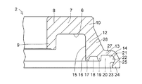
図1から図3において、四輪自動車におけるストラット型サスペンションに用いるための本例の合成樹脂製の滑り軸受1は、取付部材を介して車体側に固定される合成樹脂製の上部ケース2と、上部ケース2に対して軸心Oの回りで円周方向Rに回転自在となるように上部ケース2に重ね合わされている合成樹脂製の下部ケース3と、上部ケース2と下部ケース3間の空間4に配されている合成樹脂製の滑り軸受片5とを具備している。
1 to 3, a synthetic
上部ケース2は、特に、図4から図6に示すように、軸方向、即ち、上下方向Yにおいて円環状下面6を有した円環状の上部ケース基部7と、上部ケース基部7の径方向Xの内周端部8から垂下した内周側円筒垂下部9と、上部ケース基部7の径方向Xの外周端部10から垂下した外周側円筒垂下部11と、外周側円筒垂下部11の下端部12から径方向Xの外方に伸びる円環状鍔部13と、円環状鍔部13の円環状下面14から外周側円筒垂下部11の円筒内周面15に連接する円筒内周面16を有して上下方向Yにおいて下方に伸びる内側環状突条部17と、内側環状突条部17と協働して径方向Xの外方に内周上側環状凹部18を形成して円環状鍔部13の円環状下面14から上下方向Yにおいて下方に伸びる外側環状突条部19と、外側環状突条部19と協働して径方向Xの内方に外周上側環状凹部20を形成して円環状鍔部13の外周縁部21から垂下すると共に内周面に径方向Xの外方に漸次拡径する傾斜面部22及び傾斜面部22と連接して径方向Xの内方に漸次縮径する傾斜面部23をもって径方向Xの内方に膨出する係合膨出部24を有した係合垂下部25とを具備している。
As shown in FIGS. 4 to 6, the
円環状鍔部13は、一方の端部が外周側円筒垂下部11の円筒外周面26に連接し、他方の端部が径方向Xの外方に傾斜して円環状鍔部13の円環状上面27に連接した断面三角形状の補強リブ28によって補強されており、補強リブ28は、円環状鍔部13の円周方向Rに沿って複数個形成されている。
One end of the
下部ケース3は、特に、図7から図10に示すように、上下方向Yにおいて円環状上面29及び円環状下面30を有する円環状の下部ケース基部31と、下部ケース基部31の円環状下面30に下部ケース基部31の円筒内周面32に連接する円筒内周面33を有して上下方向Yにおいて下方に伸びる円筒突出部34と、下部ケース基部31の円環状上面29に下部ケース基部31の円筒内周面32と径方向Xの外方に環状肩部35を残して上下方向Yにおいて上方に突出すると共に下部ケース基部31の円筒外周面36に連接する円筒外周面37を有した円環状突出部38と、下部ケース基部31の円筒外周面36の下端部39に径方向Xの外方に伸びると共に環状上面40及び下部ケース基部31の円環状下面30に連接する環状下面41を有する円環状鍔部42と、下部ケース基部31の円筒外周面36に径方向Xの外方に突出すると共にその下面が円環状鍔部42の環状上面40に連接する少なくとも一つ、図7に示す本例においては、径方向Xに相対向して形成された平面視三角形状の二つの突起部43と、円環状鍔部42の環状上面40に下部ケース基部31の円筒外周面36と径方向Xの外方に内周下側環状凹部44を形成して上下方向Yにおいて上方に突出する環状突条部45と、環状突条部45と径方向Xの外方に外周下側環状凹部46を形成して上下方向Yの上方に突出すると共にその外周面に環状上面40に対し径方向Xの外方に向けて漸次縮径する傾斜面部47と、傾斜面部47と連接して径方向Xの内方に向けて漸次縮径する傾斜面部48を有して膨出する被係合膨出部49を有した係合突出部50と、係合突出部50に連接して円環状鍔部42の外周側下端部51に径方向Xの外方に伸びる環状板状部52とを具備している。
In particular, the
円筒突出部34には、その円筒内周面33に径方向Xの内方に伸びる環状突部53が形成されている。環状突部53は、円筒突出部34の径方向Xの内方への圧環強度を増す補強リブとしての役割を果たす。
The
円筒突出部34の環状端面54には、環状端面54に開口する環状凹溝55が形成されており、環状凹溝55が形成された円筒突出部34の端部56の外周面は、円筒突出部34の円筒外周面57よりも上下方向Yにおいて下方に向かって径方向Xの外方に漸次拡径する環状テーパ面58に形成されており、環状テーパ面58に形成された円筒突出部34の端部56は径方向Xに可撓性が付与されている。
The
下部ケース基部31の円環状下面30及び円環状鍔部42の環状下面41には、円筒突出部34の円筒外周面57に連接する幅広の環状凹部59が形成されており、環状凹部59は、金属製の補強部材93の接触部を形成する。
The annular
円環状突出部38の円環状上面60には、円環状上面60に開口すると共に円環状上面60から上下方向Yにおいて下方に下部ケース基部31にまで伸びた底部61を有する穴部62が円周方向Rに沿って複数個形成されている。穴部62は、図7、図8及び図9に示すように、平面視長方形の開口部63を有すると共に、開口部63の長辺63a側が上下方向Yにおいて下方に伸びるに従って漸次縮小する相対向する傾斜面64を有している。これらの穴部62は、下部ケース基部31及び円環状突出部38の肉厚を可及的に均肉にして、成形時のヒケ等の発生を極力防止させる役割を果たす。
The annular
上部ケース2と下部ケース3は、図11に示すように、上部ケース2の係合垂下部25の係合膨出部24を下部ケース3の係合突出部50の被係合膨出部49に弾性装着させて組み合わされる。弾性装着部の係合隙間Sは、円環状鍔部42の外周側下端部51に径方向Xの外方に伸びる環状板状部52によって閉塞されているので、係合隙間Sからの塵埃等の侵入は極力防止される。
As shown in FIG. 11, the
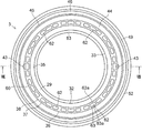
空間4に配された合成樹脂製の滑り軸受片5は、特に、図12から図18に示すように、上部ケース基部7の円環状下面6に摺動自在に接触する上下方向Yにおける円環状の上面65及び下部ケース基部31の円環状突出部38の円環状上面60に接触する円環状の下面66を有する環状のスラスト滑り軸受片部67と、スラスト滑り軸受片部67の径方向Xの外周端部68にスラスト滑り軸受片部67の円環状の上面65と連接する環状上面69を有する環状薄肉部70を介して垂下すると共に円筒内周面71及び円筒外周面72を有したラジアル滑り軸受片部73と、ラジアル滑り軸受片部73の円筒内周面71の上下方向Yにおいて下部に横断面矢視三角形状の凸部74と横断面矢視三角形状の凹部75が円周方向Rに沿って交互に形成されていると共に凸部74の頂部74aがラジアル滑り軸受片部73の円筒内周面71と面一に形成された凹凸噛合部76とを有している。
The synthetic resin sliding
滑り軸受片5は、凹凸噛合部76における凹部75に下部ケース基部31の円筒外周面36に形成された突起部43及び43が噛合することにより下部ケース3に対して軸心Oの回りで円周方向Rの回転が阻止(禁止)され、下部ケース3と一体化されるので、滑り軸受片5と下部ケース3との間で摺動することはない。本例においては、凹凸噛合部76は、ラジアル滑り軸受片部73の円筒内周面71の円周方向Rの全周にわたって形成されているが、凹凸噛合部76は、突起部43に対応するラジアル滑り軸受片部73の円筒内周面71の部位のみに形成されてもよい。
The sliding
スラスト滑り軸受片部67は、円環状の上面65に円周方向Rに沿うと共に径方向Xに少なくとも内側列と外側列の二列にわたって形成された複数個の内側凹部77及び外側凹部78を有している。
The thrust
内側列に形成された複数個の内側凹部77の夫々は、軸心Oを中心として円弧状に伸びた内側円弧状壁面79と、内側円弧状壁面79に対して径方向Xの外方で軸心Oを中心として円弧状に伸びた、即ち、内側円弧状壁面79に対して径方向Xに拡径された外側円弧状壁面80と、内側円弧状壁面79と外側円弧状壁面80の夫々に連接されていると共に互いに円周方向Rにおいて対面する一対の半円状壁面81と、内側円弧状壁面79、外側円弧状壁面80及び一対の半円状壁面81の夫々に連接された底壁面77aとで規定されている。
Each of the plurality of inner
外側列に形成された複数個の外側凹部78の夫々は、軸心Oを中心として円弧状に伸びた内側円弧状壁面82と、内側円弧状壁面82に対して径方向Xの外方で軸心Oを中心として円弧状に伸びた、即ち、内側円弧状壁面82に対して径方向Xに拡径された外側円弧状壁面83と、内側円弧状壁面82及び外側円弧状壁面83の夫々に連接されていると共に互いに円周方向Rにおいて対面する一対の半円状壁面84と、内側円弧状壁面82、外側円弧状壁面83及び一対の半円状壁面84の夫々に連接された底壁面78aとで規定されており、内側列に形成された内側凹部77間の円周方向Rの切れ目85に対応する位置に配列されており、而して、内側凹部77と外側凹部78とは、互いに円周方向Rに位相差をもって配列されている。
Each of the plurality of
スラスト滑り軸受片部67の円環状の上面65に円周方向Rに沿うと共に径方向Xに内側列と外側列の二列にわたって形成された複数個の内側凹部77及び外側凹部78は、内側凹部77及び外側凹部78の開口面86とスラスト滑り軸受面であるスラスト滑り軸受片部67の円環状の上面65とを合わせた総面積に占める内側凹部77及び外側凹部78の開口面86の総面積の割合が20〜50%、好ましくは30〜40%となるように配列されている。
A plurality of
ラジアル滑り軸受片部73は、上下方向Yの両端で開口して円筒外周面72に円周方向Rに等間隔に離間して形成された複数個の軸方向溝87を有している。
The radial sliding
スラスト滑り軸受片部67の円環状の上面65に円周方向Rに沿うと共に径方向Xに少なくとも内側列と外側列の二列にわたって形成された複数個の内側凹部77及び外側凹部78並びにラジアル滑り軸受片部73の円筒外周面72に形成された複数個の軸方向溝87は、グリース等の潤滑油剤の溜まり部となる。
A plurality of
図19及び図20に示す滑り軸受片5の他の実施の形態において、スラスト滑り軸受片部67の円環状の上面65には、円周方向Rに沿うと共に径方向Xにおいて内側列と外側列の二列にわたって形成された内側円環状凹溝88及び外側円環状凹溝89が形成されていると共に、ラジアル滑り軸受片部73の円筒外周面72に円周方向Rに等間隔に離間して複数個の軸方向溝87が形成されていてもよい。
In another embodiment of the sliding
スラスト滑り軸受片部67の円環状の上面65に円周方向Rに沿うと共に径方向Xに内側列と外側列の二列にわたって形成された内側円環状凹溝88及び外側円環状凹溝89は、内側円環状凹溝88及び外側円環状凹溝89の開口面90とスラスト滑り軸受面であるスラスト滑り軸受片部67の円環状の上面65との総面積に占める内側円環状凹溝88及び外側円環状凹溝89の開口面90の総面積の割合が20〜50%、好ましくは30〜40%となるように形成されている。
An inner
滑り軸受片5は、図1及び図3に示すように、スラスト滑り軸受片部67の円環状の下面66を円環状突出部38の円環状上面60に接触させ、ラジアル滑り軸受片部73の円筒内周面71を円環状突出部38の円筒外周面37に接触させると共に下部ケース基部31の円筒内周面32の凹凸噛合部76の凹部75に下部ケース基部31の突起部43を噛合させて、下部ケース3に対して軸心Oの回りで円周方向Rの回転を阻止させ、下部ケース3に一体化されて下部ケース3に組付けられる。
Sliding
下部ケース3に組付けられた滑り軸受片5には、スラスト滑り軸受片部67の円環状の上面65に上部ケース基部7の円環状下面6を摺動自在に接触させ、ラジアル滑り軸受片部73の円筒外周面72に上部ケース基部7の外周側円筒垂下部11の円筒内周面15を摺動自在に接触させて上部ケース2が組付けられる。
The sliding
このように形成された滑り軸受1によれば、滑り軸受片5のスラスト滑り軸受片部67と上部ケース基部7の円環状下面6及びラジアル滑り軸受片部73と上部ケース基部7の外周側円筒垂下部11の円筒内周面15との間にのみ摺動面が形成され、摺動面となるスラスト滑り軸受片部67の円環状の上面65には、円周方向Rに沿うと共に径方向Xに内側列と外側列の二列にわたって複数個の内側凹部77及び外側凹部78又は内側円環状凹溝88及び外側円環状凹溝89が形成されており、また摺動面となるラジアル滑り軸受片部73の円筒外周面72には、円周方向Rに沿って複数個の軸方向溝87が形成されているため、スラスト滑り軸受片部67の円環状の上面65と上部ケース基部7の円環状下面6との軸心Oの回りでの円周方向Rの相対回転及びラジアル滑り軸受片部73の円筒外周面72と上部ケース基部7の外周側円筒垂下部11の円筒内周面15との軸心Oの回りでの円周方向Rの相対回転において、上部ケース基部7の円環状下面6との接触面積及び上部ケース基部7の外周側円筒垂下部11の円筒内周面15との接触面積を減少させて、円環状の上面65及び外周側円筒垂下部11の円筒内周面15に作用する面圧(単位面積当たりの荷重)を高めることができ、合成樹脂同志の摩擦による低摩擦化と内側凹部77及び外側凹部78又は内側円環状凹溝88及び外側円環状凹溝89及び軸方向溝90に充填された潤滑油剤の摺動面への介在による低摩擦化とが相俟って一層の低摩擦化を図ることができる。
According to the
図21から図24に示す円筒部91と円筒部91の一方の端部に径方向Xの外方に伸びる幅広の円環状鍔部92を有した金属製の補強部材93は、幅広の円環状鍔部92の表面94を下部ケース基部31の円環状下面30及び円環状鍔部42の環状下面41に接触させ、円筒部91の円筒内周面95を下部ケース基部31の円筒突出部34の円筒外周面57に嵌挿させて下部ケース3に装着されている。
A
金属製の補強部材93が下部ケース3に装着されることにより、サスペンションコイルばねのばね座となる下部ケース3の下部ケース基部31の円環状下面30は、補強部材93によって補強される。この補強部材93を下部ケース3に装着する際、下部ケース基部31の環状テーパ面58が形成された円筒突出部34の端部56は、付与された可撓性により弾性変形して補強部材93の下部ケース基部31の円筒突出部34の円筒外周面57への嵌挿を容易に行わせ、嵌挿後においては、図23に示すように、円筒突出部34の端部56の環状テーパ面58は、下部ケース基部31の円筒突出部34の円筒外周面57よりも径方向Xの外方に弾性復元することにより、補強部材93の円筒部91の端部が上下方向Yにおいて下方への抜け出しが防止されているので、下部ケース3と補強部材93とは一体として取り扱うことができ、補強部材93を装着した滑り軸受1のストラットアッセンブリへの取り付けを容易にすることができる。
By attaching the
このようにして形成された滑り軸受1は、例えば、図25に示すように、車体側の取付部材96に上部ケース2の円環状上面7aを当接させ、サスペンションコイルばね97の上端部にばね座面としての下部ケース基部31の円環状下面30又は下部ケース基部31の円環状下面30に装着された金属製の補強部材93の円環状鍔部92を当接させて、本例の合成樹脂製の滑り軸受1を車体側の取付部材96の車体側座面98とサスペンションコイルばね97の上端部との間に配して、本例の合成樹脂製の滑り軸受1を四輪自動車のストラット型サスペンションに適用してもよい。
For example, as shown in FIG. 25, the sliding
図25に示すストラット型サスペンションでは、車体側の取付部材96に対するサスペンションコイルばね97の円周方向Rの相対回転は、滑り軸受1において、上部ケース基部7の円環状下面6に対するスラスト滑り軸受片部67の円環状の上面65及び上部ケース基部7の外周側円筒垂下部11の円筒内周面15に対するラジアル滑り軸受片部73の円筒外周面72の夫々の摺動特性に優れた合成樹脂同志の円周方向Rの相対的な摺動によって許容される。
In the strut suspension shown in FIG. 25, the relative rotation in the circumferential direction R of the
1 滑り軸受
2 上部ケース
3 下部ケース
4 空間
5 滑り軸受片
6 円環状下面
7 上部ケース基部
9 内周側円筒垂下部
11 外周側円筒垂下部
24 係合膨出部
25 係合垂下部
30 円環状下面
31 下部ケース基部
34 円筒突出部
38 円環状突出部
42 円環状鍔部
43 突起部
49 被係合膨出部
50 係合突出部
67 スラスト滑り軸受片部
73 ラジアル滑り軸受片部
74 凸部
75 凹部
76 凹凸噛合部
DESCRIPTION OF
Claims (11)
Priority Applications (10)
| Application Number | Priority Date | Filing Date | Title |
|---|---|---|---|
| JP2013028455A JP6322889B2 (en) | 2013-02-15 | 2013-02-15 | Synthetic plastic plain bearing |
| PCT/JP2014/000592 WO2014125788A1 (en) | 2013-02-15 | 2014-02-04 | Synthetic resin plain bearing |
| US14/767,700 US9539874B2 (en) | 2013-02-15 | 2014-02-04 | Synthetic resin-made sliding bearing |
| EP18180513.6A EP3404276B1 (en) | 2013-02-15 | 2014-02-04 | Synthetic resin plain bearing |
| BR112015018786-2A BR112015018786B1 (en) | 2013-02-15 | 2014-02-04 | SYNTHETIC RESIN SLIDING BEARING |
| KR1020157021759A KR101698048B1 (en) | 2013-02-15 | 2014-02-04 | Synthetic resin-made sliding bearing |
| CN201480008885.8A CN104995419B (en) | 2013-02-15 | 2014-02-04 | synthetic resin sliding bearing |
| CN201710326079.0A CN106958592B (en) | 2013-02-15 | 2014-02-04 | Synthetic resin sliding bearing |
| EP14751056.4A EP2957783B1 (en) | 2013-02-15 | 2014-02-04 | Synthetic resin plain bearing |
| US15/363,057 US9707816B2 (en) | 2013-02-15 | 2016-11-29 | Synthetic resin-made sliding bearing |
Applications Claiming Priority (1)
| Application Number | Priority Date | Filing Date | Title |
|---|---|---|---|
| JP2013028455A JP6322889B2 (en) | 2013-02-15 | 2013-02-15 | Synthetic plastic plain bearing |
Related Child Applications (1)
| Application Number | Title | Priority Date | Filing Date |
|---|---|---|---|
| JP2018054950A Division JP6631648B2 (en) | 2018-03-22 | 2018-03-22 | Slide bearing made of synthetic resin |
Publications (2)
| Publication Number | Publication Date |
|---|---|
| JP2014156907A JP2014156907A (en) | 2014-08-28 |
| JP6322889B2 true JP6322889B2 (en) | 2018-05-16 |
Family
ID=51353803
Family Applications (1)
| Application Number | Title | Priority Date | Filing Date |
|---|---|---|---|
| JP2013028455A Active JP6322889B2 (en) | 2013-02-15 | 2013-02-15 | Synthetic plastic plain bearing |
Country Status (7)
| Country | Link |
|---|---|
| US (2) | US9539874B2 (en) |
| EP (2) | EP3404276B1 (en) |
| JP (1) | JP6322889B2 (en) |
| KR (1) | KR101698048B1 (en) |
| CN (2) | CN106958592B (en) |
| BR (1) | BR112015018786B1 (en) |
| WO (1) | WO2014125788A1 (en) |
Families Citing this family (6)
| Publication number | Priority date | Publication date | Assignee | Title |
|---|---|---|---|---|
| JP6602042B2 (en) * | 2015-04-28 | 2019-11-06 | オイレス工業株式会社 | Plain bearing |
| KR102045410B1 (en) | 2015-11-20 | 2019-11-15 | 오일레스고교 가부시키가이샤 | Synthetic Resin Bearings |
| DE102017129123B4 (en) * | 2017-12-07 | 2019-10-17 | Schaeffler Technologies AG & Co. KG | Sealed rolling bearing and method for operating a rolling bearing |
| KR102062876B1 (en) * | 2018-04-13 | 2020-01-06 | 이상욱 | coil spring support for an automobile rear suspension |
| FR3108064B1 (en) * | 2020-03-10 | 2022-06-24 | Ntn Snr Roulements | Motor vehicle suspension bearing |
| KR20240010330A (en) * | 2022-07-15 | 2024-01-23 | 주식회사 일진 | Strut bearing assembly for vehicle |
Family Cites Families (24)
| Publication number | Priority date | Publication date | Assignee | Title |
|---|---|---|---|---|
| JP2538944B2 (en) | 1987-10-14 | 1996-10-02 | 富士通株式会社 | Dry etching equipment |
| JPH0434254Y2 (en) * | 1987-12-25 | 1992-08-14 | ||
| JP2600937Y2 (en) * | 1993-11-30 | 1999-11-02 | オイレス工業株式会社 | Synthetic resin bearing |
| JP3709939B2 (en) * | 1995-08-31 | 2005-10-26 | オイレス工業株式会社 | Synthetic resin bearing |
| JP4419217B2 (en) * | 1999-07-15 | 2010-02-24 | オイレス工業株式会社 | Synthetic plastic plain bearing |
| JP4482961B2 (en) * | 1999-07-15 | 2010-06-16 | オイレス工業株式会社 | Synthetic plastic plain bearing |
| JP3988397B2 (en) * | 2001-02-27 | 2007-10-10 | オイレス工業株式会社 | Synthetic plastic plain bearing |
| JP4061939B2 (en) * | 2002-03-26 | 2008-03-19 | オイレス工業株式会社 | Multi-layer plain bearing and manufacturing method thereof |
| US6929402B1 (en) * | 2002-04-11 | 2005-08-16 | Morgan Construction Company | Journal bearing and thrust pad assembly |
| JP2004225863A (en) * | 2003-01-27 | 2004-08-12 | Marugo Rubber Ind Co Ltd | Resin sliding bearing |
| JP4366946B2 (en) * | 2003-02-07 | 2009-11-18 | オイレス工業株式会社 | Thrust sliding bearing |
| JP4378983B2 (en) | 2003-03-25 | 2009-12-09 | オイレス工業株式会社 | Strut plain bearing |
| JP2006322507A (en) * | 2005-05-18 | 2006-11-30 | Jtekt Corp | Thrust bearing |
| JP2008014463A (en) * | 2006-07-07 | 2008-01-24 | Oiles Ind Co Ltd | Thrust sliding bearing, and thrust sliding bearing and piston rod combined mechanism |
| JP2008232174A (en) * | 2007-03-16 | 2008-10-02 | Jtekt Corp | Bearing for suspension |
| JP5157210B2 (en) * | 2007-03-20 | 2013-03-06 | オイレス工業株式会社 | Thrust slide bearing and combination mechanism of this thrust slide bearing with piston rod and coil spring |
| JP5233370B2 (en) * | 2008-04-02 | 2013-07-10 | オイレス工業株式会社 | Thrust sliding bearing |
| JP5245508B2 (en) | 2008-04-18 | 2013-07-24 | オイレス工業株式会社 | Thrust sliding bearing |
| DE102008057590A1 (en) * | 2008-08-13 | 2010-02-18 | Schaeffler Kg | Strut bearings |
| JP5516210B2 (en) | 2010-08-06 | 2014-06-11 | オイレス工業株式会社 | Thrust sliding bearing |
| JP5673110B2 (en) * | 2011-01-07 | 2015-02-18 | オイレス工業株式会社 | Thrust slide bearing and strut suspension mounting structure using this thrust slide bearing |
| JP5444270B2 (en) * | 2011-02-23 | 2014-03-19 | オイレス工業株式会社 | Thrust slide bearing made of synthetic resin |
| JP5906590B2 (en) | 2011-06-09 | 2016-04-20 | オイレス工業株式会社 | Synthetic plastic plain bearing |
| JP5842402B2 (en) * | 2011-06-20 | 2016-01-13 | オイレス工業株式会社 | Thrust sliding bearing |
-
2013
- 2013-02-15 JP JP2013028455A patent/JP6322889B2/en active Active
-
2014
- 2014-02-04 WO PCT/JP2014/000592 patent/WO2014125788A1/en active Application Filing
- 2014-02-04 BR BR112015018786-2A patent/BR112015018786B1/en active IP Right Grant
- 2014-02-04 EP EP18180513.6A patent/EP3404276B1/en active Active
- 2014-02-04 CN CN201710326079.0A patent/CN106958592B/en active Active
- 2014-02-04 KR KR1020157021759A patent/KR101698048B1/en active IP Right Grant
- 2014-02-04 US US14/767,700 patent/US9539874B2/en active Active
- 2014-02-04 EP EP14751056.4A patent/EP2957783B1/en active Active
- 2014-02-04 CN CN201480008885.8A patent/CN104995419B/en active Active
-
2016
- 2016-11-29 US US15/363,057 patent/US9707816B2/en active Active
Also Published As
| Publication number | Publication date |
|---|---|
| EP3404276B1 (en) | 2020-06-17 |
| BR112015018786A2 (en) | 2017-07-18 |
| JP2014156907A (en) | 2014-08-28 |
| WO2014125788A1 (en) | 2014-08-21 |
| CN104995419A (en) | 2015-10-21 |
| EP3404276A1 (en) | 2018-11-21 |
| KR101698048B1 (en) | 2017-01-19 |
| US20170072759A1 (en) | 2017-03-16 |
| US9707816B2 (en) | 2017-07-18 |
| EP2957783A4 (en) | 2016-10-19 |
| KR20150104208A (en) | 2015-09-14 |
| CN106958592A (en) | 2017-07-18 |
| BR112015018786B1 (en) | 2020-12-15 |
| CN104995419B (en) | 2017-05-31 |
| CN106958592B (en) | 2019-03-12 |
| US9539874B2 (en) | 2017-01-10 |
| US20150375591A1 (en) | 2015-12-31 |
| EP2957783B1 (en) | 2018-08-15 |
| EP2957783A1 (en) | 2015-12-23 |
Similar Documents
| Publication | Publication Date | Title |
|---|---|---|
| JP6194586B2 (en) | Synthetic plastic plain bearing | |
| JP6057814B2 (en) | Synthetic plastic plain bearing | |
| JP5910000B2 (en) | Synthetic plastic plain bearing | |
| JP6017340B2 (en) | Synthetic plastic plain bearing | |
| JP5332379B2 (en) | Synthetic plastic thrust plain bearing | |
| JP6322889B2 (en) | Synthetic plastic plain bearing | |
| JP5909976B2 (en) | Synthetic plastic plain bearing | |
| JP6631648B2 (en) | Slide bearing made of synthetic resin | |
| JP6211124B2 (en) | Synthetic plastic plain bearing | |
| WO2017094686A1 (en) | Synthetic resin sliding bearing | |
| JP2016200223A (en) | Thrust bearing for vehicle |
Legal Events
| Date | Code | Title | Description |
|---|---|---|---|
| A621 | Written request for application examination |
Free format text: JAPANESE INTERMEDIATE CODE: A621 Effective date: 20160119 |
|
| A131 | Notification of reasons for refusal |
Free format text: JAPANESE INTERMEDIATE CODE: A131 Effective date: 20161122 |
|
| A521 | Request for written amendment filed |
Free format text: JAPANESE INTERMEDIATE CODE: A523 Effective date: 20170221 |
|
| A131 | Notification of reasons for refusal |
Free format text: JAPANESE INTERMEDIATE CODE: A131 Effective date: 20170718 |
|
| A521 | Request for written amendment filed |
Free format text: JAPANESE INTERMEDIATE CODE: A523 Effective date: 20171016 |
|
| TRDD | Decision of grant or rejection written | ||
| A01 | Written decision to grant a patent or to grant a registration (utility model) |
Free format text: JAPANESE INTERMEDIATE CODE: A01 Effective date: 20180313 |
|
| A61 | First payment of annual fees (during grant procedure) |
Free format text: JAPANESE INTERMEDIATE CODE: A61 Effective date: 20180326 |
|
| R150 | Certificate of patent or registration of utility model |
Ref document number: 6322889 Country of ref document: JP Free format text: JAPANESE INTERMEDIATE CODE: R150 |
|
| R250 | Receipt of annual fees |
Free format text: JAPANESE INTERMEDIATE CODE: R250 |
|
| R250 | Receipt of annual fees |
Free format text: JAPANESE INTERMEDIATE CODE: R250 |
|
| R250 | Receipt of annual fees |
Free format text: JAPANESE INTERMEDIATE CODE: R250 |
|
| R250 | Receipt of annual fees |
Free format text: JAPANESE INTERMEDIATE CODE: R250 |