JP3988397B2 - Synthetic plastic plain bearing - Google Patents
Synthetic plastic plain bearing Download PDFInfo
- Publication number
- JP3988397B2 JP3988397B2 JP2001051630A JP2001051630A JP3988397B2 JP 3988397 B2 JP3988397 B2 JP 3988397B2 JP 2001051630 A JP2001051630 A JP 2001051630A JP 2001051630 A JP2001051630 A JP 2001051630A JP 3988397 B2 JP3988397 B2 JP 3988397B2
- Authority
- JP
- Japan
- Prior art keywords
- annular
- cylindrical portion
- sliding bearing
- peripheral surface
- inner peripheral
- Prior art date
- Legal status (The legal status is an assumption and is not a legal conclusion. Google has not performed a legal analysis and makes no representation as to the accuracy of the status listed.)
- Expired - Fee Related
Links
Images


Classifications
-
- F—MECHANICAL ENGINEERING; LIGHTING; HEATING; WEAPONS; BLASTING
- F16—ENGINEERING ELEMENTS AND UNITS; GENERAL MEASURES FOR PRODUCING AND MAINTAINING EFFECTIVE FUNCTIONING OF MACHINES OR INSTALLATIONS; THERMAL INSULATION IN GENERAL
- F16C—SHAFTS; FLEXIBLE SHAFTS; ELEMENTS OR CRANKSHAFT MECHANISMS; ROTARY BODIES OTHER THAN GEARING ELEMENTS; BEARINGS
- F16C33/00—Parts of bearings; Special methods for making bearings or parts thereof
- F16C33/02—Parts of sliding-contact bearings
- F16C33/04—Brasses; Bushes; Linings
- F16C33/06—Sliding surface mainly made of metal
- F16C33/10—Construction relative to lubrication
- F16C33/1025—Construction relative to lubrication with liquid, e.g. oil, as lubricant
- F16C33/106—Details of distribution or circulation inside the bearings, e.g. details of the bearing surfaces to affect flow or pressure of the liquid
- F16C33/1065—Grooves on a bearing surface for distributing or collecting the liquid
-
- F—MECHANICAL ENGINEERING; LIGHTING; HEATING; WEAPONS; BLASTING
- F16—ENGINEERING ELEMENTS AND UNITS; GENERAL MEASURES FOR PRODUCING AND MAINTAINING EFFECTIVE FUNCTIONING OF MACHINES OR INSTALLATIONS; THERMAL INSULATION IN GENERAL
- F16C—SHAFTS; FLEXIBLE SHAFTS; ELEMENTS OR CRANKSHAFT MECHANISMS; ROTARY BODIES OTHER THAN GEARING ELEMENTS; BEARINGS
- F16C17/00—Sliding-contact bearings for exclusively rotary movement
- F16C17/10—Sliding-contact bearings for exclusively rotary movement for both radial and axial load
-
- F—MECHANICAL ENGINEERING; LIGHTING; HEATING; WEAPONS; BLASTING
- F16—ENGINEERING ELEMENTS AND UNITS; GENERAL MEASURES FOR PRODUCING AND MAINTAINING EFFECTIVE FUNCTIONING OF MACHINES OR INSTALLATIONS; THERMAL INSULATION IN GENERAL
- F16C—SHAFTS; FLEXIBLE SHAFTS; ELEMENTS OR CRANKSHAFT MECHANISMS; ROTARY BODIES OTHER THAN GEARING ELEMENTS; BEARINGS
- F16C17/00—Sliding-contact bearings for exclusively rotary movement
- F16C17/26—Systems consisting of a plurality of sliding-contact bearings
-
- F—MECHANICAL ENGINEERING; LIGHTING; HEATING; WEAPONS; BLASTING
- F16—ENGINEERING ELEMENTS AND UNITS; GENERAL MEASURES FOR PRODUCING AND MAINTAINING EFFECTIVE FUNCTIONING OF MACHINES OR INSTALLATIONS; THERMAL INSULATION IN GENERAL
- F16C—SHAFTS; FLEXIBLE SHAFTS; ELEMENTS OR CRANKSHAFT MECHANISMS; ROTARY BODIES OTHER THAN GEARING ELEMENTS; BEARINGS
- F16C33/00—Parts of bearings; Special methods for making bearings or parts thereof
- F16C33/02—Parts of sliding-contact bearings
- F16C33/04—Brasses; Bushes; Linings
- F16C33/20—Sliding surface consisting mainly of plastics
-
- F—MECHANICAL ENGINEERING; LIGHTING; HEATING; WEAPONS; BLASTING
- F16—ENGINEERING ELEMENTS AND UNITS; GENERAL MEASURES FOR PRODUCING AND MAINTAINING EFFECTIVE FUNCTIONING OF MACHINES OR INSTALLATIONS; THERMAL INSULATION IN GENERAL
- F16C—SHAFTS; FLEXIBLE SHAFTS; ELEMENTS OR CRANKSHAFT MECHANISMS; ROTARY BODIES OTHER THAN GEARING ELEMENTS; BEARINGS
- F16C33/00—Parts of bearings; Special methods for making bearings or parts thereof
- F16C33/72—Sealings
- F16C33/74—Sealings of sliding-contact bearings
-
- B—PERFORMING OPERATIONS; TRANSPORTING
- B60—VEHICLES IN GENERAL
- B60G—VEHICLE SUSPENSION ARRANGEMENTS
- B60G2202/00—Indexing codes relating to the type of spring, damper or actuator
- B60G2202/30—Spring/Damper and/or actuator Units
- B60G2202/31—Spring/Damper and/or actuator Units with the spring arranged around the damper, e.g. MacPherson strut
- B60G2202/312—The spring being a wound spring
-
- B—PERFORMING OPERATIONS; TRANSPORTING
- B60—VEHICLES IN GENERAL
- B60G—VEHICLE SUSPENSION ARRANGEMENTS
- B60G2204/00—Indexing codes related to suspensions per se or to auxiliary parts
- B60G2204/10—Mounting of suspension elements
- B60G2204/12—Mounting of springs or dampers
- B60G2204/128—Damper mount on vehicle body or chassis
-
- B—PERFORMING OPERATIONS; TRANSPORTING
- B60—VEHICLES IN GENERAL
- B60G—VEHICLE SUSPENSION ARRANGEMENTS
- B60G2204/00—Indexing codes related to suspensions per se or to auxiliary parts
- B60G2204/40—Auxiliary suspension parts; Adjustment of suspensions
- B60G2204/418—Bearings, e.g. ball or roller bearings
-
- B—PERFORMING OPERATIONS; TRANSPORTING
- B60—VEHICLES IN GENERAL
- B60G—VEHICLE SUSPENSION ARRANGEMENTS
- B60G2204/00—Indexing codes related to suspensions per se or to auxiliary parts
- B60G2204/40—Auxiliary suspension parts; Adjustment of suspensions
- B60G2204/45—Stops limiting travel
- B60G2204/4502—Stops limiting travel using resilient buffer
-
- F—MECHANICAL ENGINEERING; LIGHTING; HEATING; WEAPONS; BLASTING
- F16—ENGINEERING ELEMENTS AND UNITS; GENERAL MEASURES FOR PRODUCING AND MAINTAINING EFFECTIVE FUNCTIONING OF MACHINES OR INSTALLATIONS; THERMAL INSULATION IN GENERAL
- F16C—SHAFTS; FLEXIBLE SHAFTS; ELEMENTS OR CRANKSHAFT MECHANISMS; ROTARY BODIES OTHER THAN GEARING ELEMENTS; BEARINGS
- F16C2208/00—Plastics; Synthetic resins, e.g. rubbers
- F16C2208/20—Thermoplastic resins
- F16C2208/40—Imides, e.g. polyimide [PI], polyetherimide [PEI]
-
- F—MECHANICAL ENGINEERING; LIGHTING; HEATING; WEAPONS; BLASTING
- F16—ENGINEERING ELEMENTS AND UNITS; GENERAL MEASURES FOR PRODUCING AND MAINTAINING EFFECTIVE FUNCTIONING OF MACHINES OR INSTALLATIONS; THERMAL INSULATION IN GENERAL
- F16C—SHAFTS; FLEXIBLE SHAFTS; ELEMENTS OR CRANKSHAFT MECHANISMS; ROTARY BODIES OTHER THAN GEARING ELEMENTS; BEARINGS
- F16C2208/00—Plastics; Synthetic resins, e.g. rubbers
- F16C2208/20—Thermoplastic resins
- F16C2208/60—Polyamides [PA]
-
- F—MECHANICAL ENGINEERING; LIGHTING; HEATING; WEAPONS; BLASTING
- F16—ENGINEERING ELEMENTS AND UNITS; GENERAL MEASURES FOR PRODUCING AND MAINTAINING EFFECTIVE FUNCTIONING OF MACHINES OR INSTALLATIONS; THERMAL INSULATION IN GENERAL
- F16C—SHAFTS; FLEXIBLE SHAFTS; ELEMENTS OR CRANKSHAFT MECHANISMS; ROTARY BODIES OTHER THAN GEARING ELEMENTS; BEARINGS
- F16C2208/00—Plastics; Synthetic resins, e.g. rubbers
- F16C2208/20—Thermoplastic resins
- F16C2208/66—Acetals, e.g. polyoxymethylene [POM]
-
- F—MECHANICAL ENGINEERING; LIGHTING; HEATING; WEAPONS; BLASTING
- F16—ENGINEERING ELEMENTS AND UNITS; GENERAL MEASURES FOR PRODUCING AND MAINTAINING EFFECTIVE FUNCTIONING OF MACHINES OR INSTALLATIONS; THERMAL INSULATION IN GENERAL
- F16C—SHAFTS; FLEXIBLE SHAFTS; ELEMENTS OR CRANKSHAFT MECHANISMS; ROTARY BODIES OTHER THAN GEARING ELEMENTS; BEARINGS
- F16C2208/00—Plastics; Synthetic resins, e.g. rubbers
- F16C2208/20—Thermoplastic resins
- F16C2208/70—Polyesters, e.g. polyethylene-terephthlate [PET], polybutylene-terephthlate [PBT]
-
- F—MECHANICAL ENGINEERING; LIGHTING; HEATING; WEAPONS; BLASTING
- F16—ENGINEERING ELEMENTS AND UNITS; GENERAL MEASURES FOR PRODUCING AND MAINTAINING EFFECTIVE FUNCTIONING OF MACHINES OR INSTALLATIONS; THERMAL INSULATION IN GENERAL
- F16C—SHAFTS; FLEXIBLE SHAFTS; ELEMENTS OR CRANKSHAFT MECHANISMS; ROTARY BODIES OTHER THAN GEARING ELEMENTS; BEARINGS
- F16C2208/00—Plastics; Synthetic resins, e.g. rubbers
- F16C2208/20—Thermoplastic resins
- F16C2208/76—Polyolefins, e.g. polyproylene [PP]
-
- F—MECHANICAL ENGINEERING; LIGHTING; HEATING; WEAPONS; BLASTING
- F16—ENGINEERING ELEMENTS AND UNITS; GENERAL MEASURES FOR PRODUCING AND MAINTAINING EFFECTIVE FUNCTIONING OF MACHINES OR INSTALLATIONS; THERMAL INSULATION IN GENERAL
- F16C—SHAFTS; FLEXIBLE SHAFTS; ELEMENTS OR CRANKSHAFT MECHANISMS; ROTARY BODIES OTHER THAN GEARING ELEMENTS; BEARINGS
- F16C2326/00—Articles relating to transporting
- F16C2326/01—Parts of vehicles in general
- F16C2326/05—Vehicle suspensions, e.g. bearings, pivots or connecting rods used therein
Landscapes
- Engineering & Computer Science (AREA)
- General Engineering & Computer Science (AREA)
- Mechanical Engineering (AREA)
- Chemical & Material Sciences (AREA)
- Oil, Petroleum & Natural Gas (AREA)
- Sliding-Contact Bearings (AREA)
- Fluid-Damping Devices (AREA)
- Sealing Of Bearings (AREA)
Description
【0001】
【発明の属する技術分野】
本発明は、合成樹脂製の滑り軸受に関し、更に詳しくは四輪自動車におけるストラット型サスペンション(マクファーソ式)に組込まれて好適な合成樹脂製の滑り軸受に関する。
【0002】
【発明が解決しようとする課題】
四輪自動車の前輪に用いられるストラット型サスペンションは、一般に、主軸と一体となった外筒の中に油圧式ショックアブソーバを内蔵したストラットアッセンブリにコイルバネを組合わせた構造をもっている。斯かるサスぺンションにおいては、ステアリング操作においてストラットアッセンブリがコイルバネと共に回る際に、ストラットアッセンブリのピストンロッドが回る形式と、ピストンロッドが回らない形式のものがあるが、いずれの形式においてもストラットアッセンブリの回動を円滑に許容するべく、車体の取付部材とコイルバネの上部バネ座シートとの間に、転がり玉軸受に代えて、合成樹脂製の滑り軸受が使用される場合がある。
【0003】
合成樹脂製の滑り軸受は、通常、合成樹脂製の下部ケースと、この下部ケースに重ねられた合成樹脂製の上部ケースとを具備し、これら下部ケースと上部ケースとの間の空間に滑り軸受片又は滑り軸受突部を配してなるが、この空間に塵埃、泥水等が侵入すると、所望の軸受機能が得られなくなってしまう虞がある。一方、ストラット型サスペンションは、車輌走行中に塵埃、雨水、泥水などが直接作用する部位に装着されるため、車体の取付部材とコイルバネの上部バネ座シートとの間に装着される滑り軸受の使用環境も極めて過酷なものとなる。したがって、滑り軸受片又は滑り軸受突部が配された空間の外周側及び内周側が直接外部に開口していると、ここからの塵埃、雨水、泥水等の空間への侵入の危険が極めて高くなり、ここでの密封性が極めて重要になる。特に、空間での水分の滞留を防止するために、空間の内周側を下方に開口させて下部ケース及び上部ケースを形成した合成樹脂製の滑り軸受では、上記の危険がますます高くなる。
【0004】
本発明は、前記諸点に鑑みてなされたものであって、滑り軸受片が配された空間の外周側及び内周側からの摺動面への塵埃、雨水、泥水等の侵入を防止し、塵埃、雨水、泥水等の侵入に起因する摺動特性の低下をなくし得て、ステアリング操作時の円滑な操舵力を長期間にわたって維持できる合成樹脂製の滑り軸受を提供することを目的とするものである。
【0005】
【課題を解決するための手段】
本発明の第一の態様の合成樹脂製の滑り軸受は、合成樹脂製の下部ケースと、この下部ケースに重ねられた合成樹脂製の上部ケースと、上部及び下部ケース間に配された合成樹脂製の円板状のスラスト滑り軸受片と、上部及び下部ケース間に配された合成樹脂製の円筒状のラジアル滑り軸受片とを具備しており、ここで、下部ケースは、内周面を有した筒部と、この筒部の一端部に一体的に形成された第一の環状板部と、この第一の環状板部の上面に一体的に形成された第一の環状突起部と、第一の環状板部の外縁に一体的に形成された環状係合突起部と、筒部の他端部に一体的に形成された第二の環状板部と、この第二の環状板部の上面に一体的に形成された第二の環状突起部とを具備しており、上部ケースは、下部ケースの筒部の内周面と同心な内周面及び外周面を有して、下部ケースの筒部内に配された円筒部と、この円筒部の一端部に一体的に形成された第三の環状板部と、この第三の環状板部の下面に一体的に形成された第一の環状垂下部と、第三の環状板部の外縁に一体的に形成された環状係合垂下部と、円筒部の他端部に一体的に形成された一対の同心の第二の環状垂下部とを具備しており、第一の環状垂下部は、第一の環状突起部と環状係合突起部とで規定される環状の第一の溝に配されており、環状係合突起部は、第一の環状垂下部と環状係合垂下部とで規定される環状の第二の溝に配されており、第二の環状突起部は、一対の第二の環状垂下部で規定される環状の第三の溝に配されており、スラスト滑り軸受片は、第一の環状突起部の内周側であって第一の環状板部の上面と第三の環状板部の下面との間に、当該上面及び下面に摺動自在に接触して配されており、ラジアル滑り軸受片は、筒部の内周面と円筒部の外周面との間に、当該内周面及び外周面に摺動自在に接触して配されている。
【0006】
第一の態様の滑り軸受によれば、第二の環状突起部が一対の第二の環状垂下部で規定される環状の第三の溝に配されているために、内周側からのラジアル滑り軸受片の摺動面への塵埃、雨水、泥水等の侵入を防止でき、塵埃、雨水、泥水等の侵入に起因する摺動特性の低下をなくし得て、ステアリング操作時の円滑な操舵力を長期間にわたって維持できる。
【0007】
本発明の第二の態様の合成樹脂製の滑り軸受では、第一の態様の滑り軸受において、第一の環状突起部は、その頂面が環状係合突起部の頂面よりも高くなるように、第一の環状板部の上面に一体的に形成されている。
【0008】
第二の態様の滑り軸受によれば、第一の環状突起部の頂面が環状係合突起部の頂面よりも高くなっているために、仮に雨水、泥水等が環状係合突起部を乗り越えたとしても、これら雨水、泥水等のスラスト滑り軸受片の摺動面への侵入を第一の環状突起部により防止でき、これによっても雨水、泥水等の侵入に起因する摺動特性の低下をなくし得て、ステアリング操作時の円滑な操舵力を長期間にわたって維持できる。
【0009】
本発明の第三の態様の合成樹脂製の滑り軸受では、第一又は第二の態様の滑り軸受において、筒部の内周面と円筒部の外周面とのうちの少なくとも一方には、ラジアル滑り軸受片の環状の下面に対面する環状段面を規定する環状の段部が形成されている。
【0010】
第三の態様の滑り軸受によれば、環状段面によりラジアル滑り軸受片の下降を防止でき、筒部の内周面と円筒部の外周面との間におけるラジアル滑り軸受片を所望位置に保持できる。
【0011】
本発明の第四の態様の合成樹脂製の滑り軸受では、第三の態様の滑り軸受において、第二の環状突起部は、その頂面が環状段面よりも低くなるように、第二の環状板部の上面に一体的に形成されている。
【0012】
第四の態様の滑り軸受によれば、第二の環状突起部の頂面が環状段面よりも低くなっているために、仮に雨水、泥水等が第二の環状突起部を乗り越えて筒部の内周面と円筒部の外周面との間に侵入しても、これら雨水、泥水等のレベルが環状段面に至ることがなく、而して、これら雨水、泥水等のスラスト滑り軸受片の摺動面への侵入を防止でき、これによっても雨水、泥水等の侵入に起因する摺動特性の低下をなくし得て、ステアリング操作時の円滑な操舵力を長期間にわたって維持できる。
【0013】
本発明の第五の態様の合成樹脂製の滑り軸受では、第一から第四のいずれかの態様の滑り軸受において、下部ケースは、第一の環状板部の上面に一体的に形成された第三の環状突起部を更に具備しており、スラスト滑り軸受片は、第三の環状突起部の外周側に配されている。
【0014】
第五の態様の滑り軸受によれば、第三の環状突起部によりスラスト滑り軸受片の径方向の移動を防止でき、第一の環状板部の上面と第三の環状板部の下面との間におけるスラスト滑り軸受片を所望位置に保持できる。
【0015】
本発明の第六の態様の合成樹脂製の滑り軸受では、第一から第五のいずれかの態様の滑り軸受において、筒部の内周面と円筒部の外周面とのうちの少なくとも一方には、ラジアル滑り軸受片の環状の上面に対面する他の環状段面を規定する他の環状の段部が形成されている。
【0016】
第六の態様の滑り軸受によれば、他の環状段面によりラジアル滑り軸受片の上昇を防止でき、筒部の内周面と円筒部の外周面との間におけるラジアル滑り軸受片を所望位置に保持できる。
【0017】
本発明における上部及び下部ケースを構成する合成樹脂は、耐摩耗性、耐衝撃性、耐クリープ性等の摺動特性及び機械的特性に優れていることが好ましく、また上部及び下部ケース間に収容されるスラスト滑り軸受片及びラジアル滑り軸受片を構成する合成樹脂は特に自己潤滑性を有することが好ましく、例えばポリアセタール樹脂、ポリアミド樹脂、ポリブチレンテレフタレート(PBT)等のポリエステル樹脂、ポリエチレン、ポリプロピレン等のポリオレフィン樹脂等が良好に使用され、このほかポリカーボネート樹脂等も使用し得る。
【0018】
上部及び下部ケースには、スラスト滑り軸受片及びラジアル滑り軸受片を構成する合成樹脂と同様の合成樹脂が使用され得るが、特にスラスト滑り軸受片及びラジアル滑り軸受片に使用される合成樹脂と摩擦特性の良好な組合わせであって、しかも比較的剛性の高い合成樹脂であることが望ましい。その望ましい組合わせについて例示すると、スラスト滑り軸受片及びラジアル滑り軸受片と上部及び下部ケースとに対して、ポリアセタールとポリアミドとの組合わせ、ポリエチレンとポリアセタールとの組合わせ、ポリアセタールとPBTとの組合わせ及びポリアセタールとポリアセタールとの組合わせがある。
【0019】
次に本発明を、図に示す好ましい実施の形態の例に基づいて更に詳細に説明する。本発明はこれら例に何等限定されないのである。
【0020】
【発明の実施の形態】
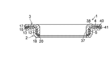
図1から図4において、本例の合成樹脂製の滑り軸受1は、合成樹脂製の下部ケース2と、下部ケース2に重ねられた合成樹脂製の上部ケース3と、上部及び下部ケース3及び2間に配された合成樹脂製の円板状のスラスト滑り軸受片4と、上部及び下部ケース3及び2間に配された合成樹脂製の円筒状のラジアル滑り軸受片5とを具備している。
【0021】
下部ケース2は、内周面11を有した筒部12と、筒部12の一端部に一体的に形成された環状板部13と、環状板部13の上面14の外側に一体的に形成された環状突起部15と、環状板部13の上面14の内側に一体的に形成された環状突起部16と、環状板部13の外縁に一体的に形成された環状係合突起部17と、筒部12の他端部に一体的に形成された環状板部18と、環状板部18の上面19に一体的に形成された環状突起部20とを具備している。
【0022】
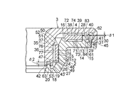
筒部12は、内周面11の一部である円筒状の内周面24を有した円筒部25と、円筒部25に一体的に形成されていると共に内周面11の他の一部である円錐状の内周面26を有した円錐状の筒部27とからなり、環状突起部15は、その頂面28が環状係合突起部17の頂面29よりもδ1だけ高くなるように、環状板部13の上面14に一体的に形成されており、環状係合突起部17は、ほぼ中央に外に膨出する環状の膨大部30と、膨大部30の外面に環状の傾斜係合面31とを具備している。
【0023】
上部ケース3は、円筒部25の内周面24と同心な内周面35及び外周面36を有して、筒部12内に配された円筒部37と、円筒部37の一端部に一体的に形成された環状板部38と、環状板部38の下面39の外側に一体的に形成された環状垂下部40と、環状板部38の外縁に一体的に形成された環状係合垂下部41と、円筒部37の他端部に一体的に形成された一対の同心の環状垂下部42及び43とを具備している。
【0024】
環状係合垂下部41は、下部に内に膨出する膨大部45と、膨大部45の内面に環状の傾斜係合面46とを具備しており、傾斜係合面46は、傾斜係合面31に対面している。筒部12の内周面11と円筒部37の外周面36とのうちの少なくとも一方、本例では筒部12の内周面11には、ラジアル滑り軸受片5の環状の下面47に対面する環状段面48を規定する環状の段部49が形成されており、内周面24と内周面26とは、環状段面48を介して連接しており、筒部12の内周面11と円筒部37の外周面36とのうちの少なくとも一方、本例では円筒部37の外周面36には、ラジアル滑り軸受片5の環状の上面50に対面する環状段面51を規定する環状の段部52が形成されており、環状突起部20は、その頂面53が環状段面48よりもδ2だけ低くなるように、環状板部18の上面19に一体的に形成されている。
【0025】
環状垂下部40は、環状突起部15と環状係合突起部17とで規定される環状の溝61に配されており、環状係合突起部17は、環状垂下部40と環状係合垂下部41とで規定される環状の溝62に配されており、環状突起部20は、一対の環状垂下部42及び43で規定される環状の溝63に配されている。
【0026】
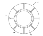
スラスト滑り軸受片4は、環状突起部15の内周側であって環状突起部16の外周側であり、しかも、環状板部13の上面14と環状板部38の下面39との間に、当該上面14及び下面39に摺動自在に接触して配されており、上面14及び下面39に夫々摺動自在に接触する環状の下面71及び上面72を有したスラスト滑り軸受片4において、その下面71及び72の夫々には、径方向に伸びたグリース(潤滑油材)溜め用の複数の溝73及び74が円周方向に等間隔に夫々形成されている。
【0027】
ラジアル滑り軸受片5は、円筒部25の内周面24と円筒部37の外周面36との間に、当該内周面24及び外周面36に摺動自在に接触して配されており、内周面24及び外周面36に夫々摺動自在に接触した外周面75及び内周面76を有したラジアル滑り軸受片5において、その内周面76には、軸方向に伸びたグリース(潤滑油材)溜め用の複数の溝77が円周方向に等間隔に夫々形成されている。
【0028】
以上の合成樹脂製の滑り軸受1は、図5に示すように、ストラットアッセンブリにおけるショックアブソーバのピストンロッド81を、滑り軸受1の内周面35で規定される挿通孔に貫通させ、ピストンロッド81の一端が取り付けられる車体側の取付部材82に上部ケース3の環状の上面83をぴったりと当接させ、下部ケース2の環状の下面84を、ストラットアッセンブリにおけるコイルバネ85の上部バネ座シート86にぴったりと当接させて、上部バネ座シート86と取付部材82との間に装着されて用いられる。この際、内周面35は取付部材82の円筒部87の外周面にぴったりと当接される。
【0029】
ステアリング操作によりストラットアッセンブリが回動されると、上部ケース3に対して下部ケース2が回転され、下部ケース2のこの回転は、上部及び下部ケース3及び2間に配されたスラスト滑り軸受4及びラジアル滑り軸受5により滑らかになされ、したがってステアリング操作も抵抗なく行われる。また、上部及び下部ケース3及び2間の空間91への塵埃等の侵入は、内周側では環状突起部20と環状垂下部42及び43とで形成されるラビリンスにより、外周側では環状突起部15及び環状係合突起部17と環状垂下部40及び環状係合垂下部41とで形成されるラビリンスにより防止され、而してこれら両ラビリンス間に配されたスラスト滑り軸受片4及びラジアル滑り軸受片5の各摺動面への塵埃等の侵入が確実に防止される。
【0030】
滑り軸受1によれば、環状突起部20が一対の環状垂下部42及び43で規定される溝63に配されているために、内周側からのラジアル滑り軸受片5の摺動面である外周面及び内周面75及び76への塵埃、雨水、泥水等の侵入を防止でき、塵埃、雨水、泥水等の侵入に起因する摺動特性の低下をなくし得てステアリング操作時の円滑な操舵力を長期間にわたって維持できる。
【0031】
また、滑り軸受1によれば、環状突起部15の頂面28が環状係合突起部17の頂面29よりもδ1だけ高くなっているために、仮に雨水、泥水等が環状係合突起部17を乗り越えたとしても、これら雨水、泥水等のスラスト滑り軸受片4の摺動面である下面71及び上面72への侵入を環状突起部15により防止でき、これによっても雨水、泥水等の侵入に起因する摺動特性の低下をなくし得て、ステアリング操作時の円滑な操舵力を長期間にわたって維持でき、また、環状段面48によりラジアル滑り軸受片5の下降を防止でき、筒部12の内周面11と円筒部37の外周面36との間におけるラジアル滑り軸受片5を所望位置に保持でき、環状突起部20の頂面53が環状段面48よりもδ2だけ低くなっているために、仮に雨水、泥水等が環状突起部20を乗り越えたとしても、これら雨水、泥水等のレベルが環状段面48に至ることがなく、而して、これら雨水、泥水等のラジアル滑り軸受片5の摺動面への侵入を防止でき、これによっても雨水、泥水等の侵入に起因する摺動特性の低下をなくし得て、ステアリング操作時の円滑な操舵力を長期間にわたって維持でき、更に、環状突起部16によりスラスト滑り軸受片4の径方向の移動を防止でき、環状板部13の上面14と環状板部38の下面39との間におけるスラスト滑り軸受片4を所望位置に保持でき、加えて、環状段面51によりラジアル滑り軸受片5の上昇を防止でき、筒部12の内周面11と円筒部37の外周面36との間におけるラジアル滑り軸受片5を所望位置に保持できる。
【0032】
なお、互いに対面する傾斜係合面31と傾斜係合面46とを、環状係合突起部17と環状係合垂下部41との弾性により互いに弾性的に接触させて、これによりラビリンスの密封手段に加えて弾性密封手段を構成してもよいが、これに代えて、傾斜係合面31と傾斜係合面46とを微小隙間をもって互いに対面させてもよい。また、溝77を内周面76に設けたが、これと共に又はこれに代えて、外周面75に溝77を設けてもよい。
【0033】
【発明の効果】
本発明によれば、滑り軸受片が配された空間の外周側及び内周側からの摺動面への塵埃、雨水、泥水等の侵入を防止し、塵埃、雨水、泥水等の侵入に起因する摺動特性の低下をなくし得てステアリング操作時の円滑な操舵力を長期間にわたって維持できる合成樹脂製の滑り軸受を提供できる。
【図面の簡単な説明】
【図1】本発明の実施の形態の好ましい一例の断面図である。
【図2】図1に示す例の一部拡大断面図である。
【図3】図1に示す例のスラスト滑り軸受片の平面図である。
【図4】図1に示す例のラジアル滑り軸受片の斜視図である。
【図5】図1に示す例をストラットアッセンブリに用いた例の断面説明図である。
【符号の説明】
1 合成樹脂製の滑り軸受
2 下部ケース
3 上部ケース
4 スラスト滑り軸受片
5 ラジアル滑り軸受片[0001]
BACKGROUND OF THE INVENTION
The present invention relates to a synthetic resin sliding bearing, and more particularly to a synthetic resin sliding bearing suitable for being incorporated in a strut suspension (McFarso type) in a four-wheeled vehicle.
[0002]
[Problems to be solved by the invention]
A strut suspension used for a front wheel of a four-wheeled vehicle generally has a structure in which a coil spring is combined with a strut assembly in which a hydraulic shock absorber is incorporated in an outer cylinder integrated with a main shaft. In such suspension, there are a type in which the piston rod of the strut assembly rotates and a type in which the piston rod does not rotate when the strut assembly rotates together with the coil spring in the steering operation. In order to allow rotation smoothly, a synthetic resin sliding bearing may be used instead of the rolling ball bearing between the mounting member of the vehicle body and the upper spring seat of the coil spring.
[0003]
A synthetic resin sliding bearing usually comprises a synthetic resin lower case and a synthetic resin upper case superimposed on the lower case, and a sliding bearing in a space between the lower case and the upper case. Although a piece or a sliding bearing protrusion is provided, if dust, muddy water, or the like enters the space, a desired bearing function may not be obtained. On the other hand, the strut type suspension is mounted on a part where dust, rainwater, muddy water, etc. directly act while the vehicle is running, so a slide bearing mounted between the mounting member of the vehicle body and the upper spring seat of the coil spring is used. The environment is also extremely harsh. Therefore, if the outer peripheral side and inner peripheral side of the space where the sliding bearing piece or the sliding bearing protrusion is arranged are directly open to the outside, there is a very high risk of dust, rainwater, muddy water, etc. entering the space. Therefore, the sealing performance here is extremely important. In particular, in the case of a synthetic resin plain bearing in which a lower case and an upper case are formed by opening the inner peripheral side of the space downward in order to prevent moisture from staying in the space, the above risk becomes higher.
[0004]
The present invention has been made in view of the above points, and prevents intrusion of dust, rainwater, muddy water, etc. into the sliding surface from the outer peripheral side and inner peripheral side of the space where the sliding bearing piece is arranged, An object of the present invention is to provide a synthetic resin sliding bearing that can eliminate the deterioration of sliding characteristics due to intrusion of dust, rainwater, muddy water, etc., and can maintain a smooth steering force during steering operation over a long period of time. It is.
[0005]
[Means for Solving the Problems]
The synthetic resin sliding bearing of the first aspect of the present invention includes a synthetic resin lower case, a synthetic resin upper case overlaid on the lower case, and a synthetic resin disposed between the upper and lower cases. A disc-shaped thrust sliding bearing piece made of plastic and a cylindrical radial sliding bearing piece made of synthetic resin disposed between the upper and lower cases, wherein the lower case has an inner peripheral surface. A cylindrical portion having a first annular plate portion integrally formed on one end portion of the cylindrical portion, and a first annular protrusion portion integrally formed on an upper surface of the first annular plate portion; An annular engagement protrusion formed integrally on the outer edge of the first annular plate portion, a second annular plate portion integrally formed on the other end of the cylindrical portion, and the second annular plate A second annular projection formed integrally on the upper surface of the upper part, and the upper case is an inner peripheral surface of the cylindrical part of the lower case A cylindrical portion having a concentric inner peripheral surface and an outer peripheral surface and arranged in the cylindrical portion of the lower case, a third annular plate portion integrally formed at one end of the cylindrical portion, and the third A first annular hanging portion integrally formed on the lower surface of the annular plate portion, an annular engaging hanging portion integrally formed on the outer edge of the third annular plate portion, and the other end portion of the cylindrical portion. A pair of concentric second annular hanging portions formed integrally with each other, and the first annular hanging portion has an annular shape defined by the first annular projection and the annular engagement projection. The annular engagement protrusion is disposed in the first groove, and the annular engagement protrusion is disposed in the annular second groove defined by the first annular suspension and the annular engagement suspension. The protrusion is disposed in an annular third groove defined by the pair of second annular hanging portions, and the thrust slide bearing piece is on the inner peripheral side of the first annular protrusion and the first ring Between the upper surface of the plate portion and the lower surface of the third annular plate portion, the upper surface and the lower surface are slidably in contact with each other. Between the outer peripheral surface and the inner peripheral surface and the outer peripheral surface.
[0006]
According to the slide bearing of the first aspect, since the second annular protrusion is arranged in the annular third groove defined by the pair of second annular hanging portions, the radial from the inner peripheral side Smooth sliding force during steering operation can be prevented by preventing the entry of dust, rainwater, muddy water, etc. into the sliding surface of the sliding bearing piece, and eliminating the deterioration of sliding characteristics caused by the entry of dust, rainwater, muddy water, etc. Can be maintained over a long period of time.
[0007]
In the sliding bearing made of a synthetic resin according to the second aspect of the present invention, in the sliding bearing according to the first aspect, the top surface of the first annular protrusion is higher than the top surface of the annular engagement protrusion. Further, it is integrally formed on the upper surface of the first annular plate portion.
[0008]
According to the slide bearing of the second aspect, since the top surface of the first annular projection is higher than the top surface of the annular engagement projection, tentatively rainwater, muddy water, etc. Even if it gets over, the first annular protrusion can prevent the rain slide and muddy water from entering the sliding surface of the thrust slide bearing piece, and this also reduces the sliding characteristics due to the penetration of rain water and muddy water. Thus, the smooth steering force during the steering operation can be maintained over a long period of time.
[0009]
In the synthetic resin-made sliding bearing of the third aspect of the present invention, in the sliding bearing of the first or second aspect, at least one of the inner peripheral surface of the cylindrical portion and the outer peripheral surface of the cylindrical portion is radial. An annular step portion that defines an annular step surface facing the annular lower surface of the slide bearing piece is formed.
[0010]
According to the slide bearing of the third aspect, the radial slide bearing piece can be prevented from descending by the annular step surface, and the radial slide bearing piece between the inner peripheral surface of the cylindrical portion and the outer peripheral surface of the cylindrical portion is held at a desired position. it can.
[0011]
In the synthetic resin-made sliding bearing of the fourth aspect of the present invention, in the sliding bearing of the third aspect, the second annular protrusion has the second surface so that the top surface is lower than the annular step surface. It is integrally formed on the upper surface of the annular plate portion.
[0012]
According to the slide bearing of the fourth aspect, the top surface of the second annular projection is lower than the annular step surface, so that rainwater, muddy water, etc. get over the second annular projection and the cylinder portion The level of rainwater, muddy water, etc. does not reach the annular step surface even if it penetrates between the inner peripheral surface of the cylinder and the outer peripheral surface of the cylindrical portion, so that the thrust slide bearing piece of these rainwater, muddy water, etc. Can be prevented from entering the sliding surface, which can eliminate the deterioration of the sliding characteristics due to the intrusion of rainwater, muddy water, etc., and maintain a smooth steering force during steering operation over a long period of time.
[0013]
In the synthetic resin sliding bearing of the fifth aspect of the present invention, in the sliding bearing of any one of the first to fourth aspects, the lower case is integrally formed on the upper surface of the first annular plate portion. A third annular protrusion is further provided, and the thrust slide bearing piece is disposed on the outer peripheral side of the third annular protrusion.
[0014]
According to the sliding bearing of the fifth aspect, the radial movement of the thrust sliding bearing piece can be prevented by the third annular protrusion, and the upper surface of the first annular plate portion and the lower surface of the third annular plate portion can be prevented. The thrust sliding bearing piece in between can be held in a desired position.
[0015]
In the synthetic resin sliding bearing of the sixth aspect of the present invention, in the sliding bearing of any one of the first to fifth aspects, at least one of the inner peripheral surface of the cylindrical portion and the outer peripheral surface of the cylindrical portion is provided. Is formed with another annular step portion that defines another annular step surface facing the annular upper surface of the radial sliding bearing piece.
[0016]
According to the slide bearing of the sixth aspect, the radial slide bearing piece can be prevented from rising by the other annular step surface, and the radial slide bearing piece between the inner peripheral surface of the cylindrical portion and the outer peripheral surface of the cylindrical portion is placed at a desired position. Can be retained.
[0017]
The synthetic resin constituting the upper and lower cases in the present invention is preferably excellent in sliding properties and mechanical properties such as wear resistance, impact resistance and creep resistance, and is accommodated between the upper and lower cases. The synthetic resin constituting the thrust sliding bearing piece and the radial sliding bearing piece is preferably self-lubricating, for example, polyacetal resin, polyamide resin, polyester resin such as polybutylene terephthalate (PBT), polyethylene, polypropylene, etc. Polyolefin resins and the like are favorably used, and polycarbonate resins and the like can also be used.
[0018]
For the upper and lower cases, the same synthetic resin as the synthetic resin constituting the thrust sliding bearing piece and the radial sliding bearing piece can be used, but especially the synthetic resin used for the thrust sliding bearing piece and the radial sliding bearing piece and friction. It is desirable that the synthetic resin is a combination having good characteristics and relatively high rigidity. Examples of the desired combinations include the combination of polyacetal and polyamide, the combination of polyethylene and polyacetal, and the combination of polyacetal and PBT for the thrust slide bearing piece and the radial slide bearing piece and the upper and lower cases. And combinations of polyacetal and polyacetal.
[0019]
Next, the present invention will be described in more detail based on an example of a preferred embodiment shown in the drawings. The present invention is not limited to these examples.
[0020]
DETAILED DESCRIPTION OF THE INVENTION
1 to 4, a synthetic resin sliding bearing 1 of this example includes a synthetic resin
[0021]
The
[0022]
The
[0023]
The
[0024]
The annular
[0025]
The
[0026]
The thrust
[0027]
The radial sliding
[0028]
As shown in FIG. 5, the above-described synthetic resin sliding bearing 1 allows a
[0029]
When the strut assembly is rotated by the steering operation, the
[0030]
According to the slide bearing 1, since the
[0031]
Further, according to the sliding bearing 1, since the
[0032]
The inclined engagement surface 31 and the
[0033]
【The invention's effect】
According to the present invention, dust, rainwater, muddy water, and the like are prevented from entering the sliding surfaces from the outer peripheral side and inner peripheral side of the space where the sliding bearing pieces are arranged, resulting from the intrusion of dust, rainwater, muddy water, etc. It is possible to provide a sliding bearing made of a synthetic resin that can eliminate the deterioration of the sliding characteristics and maintain a smooth steering force during steering operation for a long period of time.
[Brief description of the drawings]
FIG. 1 is a cross-sectional view of a preferred example of an embodiment of the present invention.
FIG. 2 is a partially enlarged cross-sectional view of the example shown in FIG.
3 is a plan view of the thrust slide bearing piece of the example shown in FIG. 1. FIG.
4 is a perspective view of the radial sliding bearing piece of the example shown in FIG. 1. FIG.
FIG. 5 is a cross-sectional explanatory view of an example in which the example shown in FIG. 1 is used in a strut assembly.
[Explanation of symbols]
DESCRIPTION OF SYMBOLS 1 Synthetic
Claims (3)
Priority Applications (6)
| Application Number | Priority Date | Filing Date | Title |
|---|---|---|---|
| JP2001051630A JP3988397B2 (en) | 2001-02-27 | 2001-02-27 | Synthetic plastic plain bearing |
| CNB028053095A CN100462579C (en) | 2001-02-27 | 2002-02-25 | Sliding bearings made of synthetic resin |
| PCT/JP2002/001671 WO2002068835A1 (en) | 2001-02-27 | 2002-02-25 | Synthetic resin sliding bearing |
| EP02700749.1A EP1365162B1 (en) | 2001-02-27 | 2002-02-25 | Synthetic resin sliding bearing |
| KR1020037009904A KR100616146B1 (en) | 2001-02-27 | 2002-02-25 | Synthetic Resin Sliding Bearing |
| US10/451,525 US6918701B2 (en) | 2001-02-27 | 2002-02-25 | Synthetic resin-made sliding bearing |
Applications Claiming Priority (1)
| Application Number | Priority Date | Filing Date | Title |
|---|---|---|---|
| JP2001051630A JP3988397B2 (en) | 2001-02-27 | 2001-02-27 | Synthetic plastic plain bearing |
Publications (2)
| Publication Number | Publication Date |
|---|---|
| JP2002257146A JP2002257146A (en) | 2002-09-11 |
| JP3988397B2 true JP3988397B2 (en) | 2007-10-10 |
Family
ID=18912377
Family Applications (1)
| Application Number | Title | Priority Date | Filing Date |
|---|---|---|---|
| JP2001051630A Expired - Fee Related JP3988397B2 (en) | 2001-02-27 | 2001-02-27 | Synthetic plastic plain bearing |
Country Status (6)
| Country | Link |
|---|---|
| US (1) | US6918701B2 (en) |
| EP (1) | EP1365162B1 (en) |
| JP (1) | JP3988397B2 (en) |
| KR (1) | KR100616146B1 (en) |
| CN (1) | CN100462579C (en) |
| WO (1) | WO2002068835A1 (en) |
Families Citing this family (45)
| Publication number | Priority date | Publication date | Assignee | Title |
|---|---|---|---|---|
| JP4099996B2 (en) | 2002-01-22 | 2008-06-11 | オイレス工業株式会社 | Thrust sliding bearing |
| JP4288930B2 (en) * | 2002-10-03 | 2009-07-01 | オイレス工業株式会社 | Plain bearing |
| US7993061B2 (en) | 2002-10-03 | 2011-08-09 | Oiles Corporation | Sliding bearing |
| CN100436850C (en) * | 2002-10-03 | 2008-11-26 | 奥依列斯工业株式会社 | Sliding bearing |
| JP4366946B2 (en) | 2003-02-07 | 2009-11-18 | オイレス工業株式会社 | Thrust sliding bearing |
| JP4378983B2 (en) | 2003-03-25 | 2009-12-09 | オイレス工業株式会社 | Strut plain bearing |
| US20060280597A1 (en) * | 2003-06-11 | 2006-12-14 | Ishikawajima-Harima Heavy Industries Co., Ltd. | Rotating member, housing, bearing, gearbox, rotating machine, shaft structure, and surface treatment method |
| DE10355136A1 (en) * | 2003-11-26 | 2005-06-23 | Valeo Klimasysteme Gmbh | operating element |
| DE102005054113B4 (en) * | 2005-11-12 | 2017-11-09 | Schaeffler Technologies AG & Co. KG | thrust washer |
| JP5561660B2 (en) * | 2006-05-12 | 2014-07-30 | オイレス工業株式会社 | Plain bearing |
| JP4997822B2 (en) * | 2006-05-15 | 2012-08-08 | オイレス工業株式会社 | Plain bearing |
| DE102007005111B4 (en) * | 2007-02-01 | 2009-07-09 | BSH Bosch und Siemens Hausgeräte GmbH | Slide bearing for a household appliance |
| JP5029058B2 (en) | 2007-02-20 | 2012-09-19 | オイレス工業株式会社 | Thrust slide bearing and combination mechanism of this thrust slide bearing and piston rod |
| JP5157210B2 (en) * | 2007-03-20 | 2013-03-06 | オイレス工業株式会社 | Thrust slide bearing and combination mechanism of this thrust slide bearing with piston rod and coil spring |
| JP5347966B2 (en) * | 2007-09-27 | 2013-11-20 | オイレス工業株式会社 | Synthetic plastic thrust plain bearing |
| DE102009012339A1 (en) * | 2008-03-18 | 2009-09-24 | Luk Lamellen Und Kupplungsbau Beteiligungs Kg | Stampable pressure disc with cut out flow openings |
| JP5233370B2 (en) * | 2008-04-02 | 2013-07-10 | オイレス工業株式会社 | Thrust sliding bearing |
| JP5332379B2 (en) | 2008-07-28 | 2013-11-06 | オイレス工業株式会社 | Synthetic plastic thrust plain bearing |
| JP5106293B2 (en) * | 2008-07-29 | 2012-12-26 | カヤバ工業株式会社 | Hydraulic shock absorber |
| DE102008057590A1 (en) | 2008-08-13 | 2010-02-18 | Schaeffler Kg | Strut bearings |
| JP5190827B2 (en) * | 2009-06-12 | 2013-04-24 | オイレス工業株式会社 | Strut plain bearing |
| FR2948066B1 (en) * | 2009-07-17 | 2012-01-20 | Skf Ab | SUSPENSION STOP DEVICE AND FORCE LEG. |
| DE202009013211U1 (en) | 2009-09-02 | 2011-01-13 | Becker Marine Systems Gmbh & Co. Kg | Upper Rudertraglager |
| DE102010011816A1 (en) | 2010-03-18 | 2011-09-22 | Schaeffler Technologies Gmbh & Co. Kg | Suspension strut slide bearing for use in strut arrangement of car, has radial sliding member supported between two supporting portions, and housing portions held together, so that supporting portions are axially held together |
| DE102010026854A1 (en) | 2010-07-12 | 2012-01-12 | Schaeffler Technologies Gmbh & Co. Kg | Strut slide bearing, has guide ring formed from spring seat and friction element as single-piece component, where spring seat is made of material comprising higher elastic modulus than material of friction element |
| JP5516210B2 (en) * | 2010-08-06 | 2014-06-11 | オイレス工業株式会社 | Thrust sliding bearing |
| DE102010035188A1 (en) | 2010-08-24 | 2012-03-01 | Schaeffler Technologies Gmbh & Co. Kg | Strut slide bearing for steered wheel of motor vehicle i.e. two-track vehicle, has guide ring comprising reinforcement that is enclosed with material of ring such that free surface of reinforcement is cooperated with cap or sliding washer |
| DE102010036242A1 (en) | 2010-09-03 | 2012-03-08 | Schaeffler Technologies Gmbh & Co. Kg | Suspension strut bearing for motor vehicle, has guide ring and spring seat which are arranged between sliding element and helical spring, where spring seat comprises slit for receiving free end of bellow |
| JP5673110B2 (en) | 2011-01-07 | 2015-02-18 | オイレス工業株式会社 | Thrust slide bearing and strut suspension mounting structure using this thrust slide bearing |
| CN102817905A (en) * | 2011-06-11 | 2012-12-12 | 邹高万 | Plastic slide block bearing |
| JP5842402B2 (en) * | 2011-06-20 | 2016-01-13 | オイレス工業株式会社 | Thrust sliding bearing |
| JP5909976B2 (en) * | 2011-10-07 | 2016-04-27 | オイレス工業株式会社 | Synthetic plastic plain bearing |
| DE102013201965A1 (en) * | 2013-02-07 | 2014-08-07 | Schaeffler Technologies Gmbh & Co. Kg | Strut mounts |
| JP6017340B2 (en) | 2013-02-15 | 2016-10-26 | オイレス工業株式会社 | Synthetic plastic plain bearing |
| JP6322889B2 (en) * | 2013-02-15 | 2018-05-16 | オイレス工業株式会社 | Synthetic plastic plain bearing |
| CN103148097B (en) * | 2013-03-08 | 2016-03-09 | 山西新环橡塑制品有限公司 | A kind of automobile pressure bearing |
| JP6057814B2 (en) * | 2013-04-11 | 2017-01-11 | オイレス工業株式会社 | Synthetic plastic plain bearing |
| JP6303239B2 (en) * | 2014-08-12 | 2018-04-04 | オイレス工業株式会社 | Thrust sliding bearing |
| JP2017089666A (en) | 2015-11-02 | 2017-05-25 | オイレス工業株式会社 | Synthetic resin-made slide bearing |
| DE102015119692B4 (en) * | 2015-11-13 | 2025-03-13 | Thyssenkrupp Ag | Mounting arrangement of a suspension spring for a spring strut |
| KR102045410B1 (en) * | 2015-11-20 | 2019-11-15 | 오일레스고교 가부시키가이샤 | Synthetic Resin Bearings |
| US10363786B1 (en) * | 2018-03-23 | 2019-07-30 | Federal-Mogul Motorparts Llc | Ball socket assembly with a low friction bearing |
| WO2021026106A1 (en) * | 2019-08-06 | 2021-02-11 | Firestone Industrial Products Company, Llc | Mounting assemblies as well as gas spring and damper assemblies and suspension systems including same |
| KR102772990B1 (en) * | 2020-06-03 | 2025-02-27 | 현대모비스 주식회사 | Rotation induction device for vehicle |
| US12110920B2 (en) * | 2022-06-27 | 2024-10-08 | Freudenberg-Nok General Partnership | High performance plastic radial bearings for rotating and reciprocating applications |
Family Cites Families (12)
| Publication number | Priority date | Publication date | Assignee | Title |
|---|---|---|---|---|
| US4969752A (en) * | 1986-09-01 | 1990-11-13 | Oiles Industry Co., Ltd. | Thrust bearing made of synthetic resin |
| US4854745A (en) * | 1986-09-01 | 1989-08-08 | Oiles Industry Co., Ltd. | Thrust bearing made of synthetic resin |
| JP3155405B2 (en) | 1993-07-19 | 2001-04-09 | オーツタイヤ株式会社 | Running body with lug |
| JP2600937Y2 (en) * | 1993-11-30 | 1999-11-02 | オイレス工業株式会社 | Synthetic resin bearing |
| JPH0885809A (en) | 1994-09-19 | 1996-04-02 | Nkk Corp | How to remove residual iron from blast furnace gutter |
| JPH08159160A (en) * | 1994-12-01 | 1996-06-18 | Oiles Ind Co Ltd | Synthetic resin thrust bearing |
| JP3671459B2 (en) * | 1995-06-02 | 2005-07-13 | オイレス工業株式会社 | Synthetic plastic thrust bearing |
| JP3646951B2 (en) * | 1996-09-09 | 2005-05-11 | 光洋精工株式会社 | Sealed roller bearings in rolling mills. |
| JP3921714B2 (en) * | 1996-10-21 | 2007-05-30 | オイレス工業株式会社 | Thrust bearing made of synthetic resin |
| JPH10159160A (en) | 1996-11-30 | 1998-06-16 | Inoac Corp | Joint seal material |
| JP3887891B2 (en) | 1997-06-25 | 2007-02-28 | オイレス工業株式会社 | Synthetic plastic thrust bearing |
| JP4419217B2 (en) * | 1999-07-15 | 2010-02-24 | オイレス工業株式会社 | Synthetic plastic plain bearing |
-
2001
- 2001-02-27 JP JP2001051630A patent/JP3988397B2/en not_active Expired - Fee Related
-
2002
- 2002-02-25 WO PCT/JP2002/001671 patent/WO2002068835A1/en not_active Ceased
- 2002-02-25 US US10/451,525 patent/US6918701B2/en not_active Expired - Lifetime
- 2002-02-25 KR KR1020037009904A patent/KR100616146B1/en not_active Expired - Fee Related
- 2002-02-25 EP EP02700749.1A patent/EP1365162B1/en not_active Expired - Lifetime
- 2002-02-25 CN CNB028053095A patent/CN100462579C/en not_active Expired - Fee Related
Also Published As
| Publication number | Publication date |
|---|---|
| EP1365162B1 (en) | 2014-05-21 |
| WO2002068835A1 (en) | 2002-09-06 |
| CN100462579C (en) | 2009-02-18 |
| US6918701B2 (en) | 2005-07-19 |
| US20040028303A1 (en) | 2004-02-12 |
| KR100616146B1 (en) | 2006-08-25 |
| EP1365162A4 (en) | 2006-08-30 |
| JP2002257146A (en) | 2002-09-11 |
| KR20030074747A (en) | 2003-09-19 |
| CN1492973A (en) | 2004-04-28 |
| EP1365162A1 (en) | 2003-11-26 |
Similar Documents
| Publication | Publication Date | Title |
|---|---|---|
| JP3988397B2 (en) | Synthetic plastic plain bearing | |
| EP2719910B1 (en) | Synthetic-resin plain bearing | |
| US7198406B2 (en) | Thrust sliding bearing | |
| RU2427732C2 (en) | Friction bearing | |
| KR101085594B1 (en) | Thrust slide bearing | |
| RU2427733C2 (en) | Friction bearing | |
| JP4482961B2 (en) | Synthetic plastic plain bearing | |
| JP4419217B2 (en) | Synthetic plastic plain bearing | |
| US9239081B2 (en) | Synthetic resin-made sliding bearing | |
| JP4325198B2 (en) | Synthetic resin sliding bearing and mounting structure of strut suspension using this sliding bearing | |
| JP4380177B2 (en) | Thrust sliding bearing | |
| JPH10122233A (en) | Thrust bearing made of synthetic resin | |
| JPH04105218U (en) | Synthetic resin thrust bearing | |
| JPH1113768A (en) | Synthetic resin thrust bearing | |
| JP4318268B2 (en) | Synthetic resin bearing | |
| JP4788803B2 (en) | Thrust sliding bearing | |
| WO2017094686A1 (en) | Synthetic resin sliding bearing | |
| JP4337364B2 (en) | Thrust sliding bearing | |
| JPH0131777Y2 (en) | ||
| KR960001358Y1 (en) | Synthetic thrust bearing | |
| JPH07301226A (en) | Synthetic resin thrust bearing | |
| JPH0729321U (en) | Synthetic resin thrust bearing | |
| JPH0722124U (en) | Synthetic resin thrust bearing |
Legal Events
| Date | Code | Title | Description |
|---|---|---|---|
| A621 | Written request for application examination |
Free format text: JAPANESE INTERMEDIATE CODE: A621 Effective date: 20040512 |
|
| A131 | Notification of reasons for refusal |
Free format text: JAPANESE INTERMEDIATE CODE: A131 Effective date: 20070313 |
|
| A521 | Request for written amendment filed |
Free format text: JAPANESE INTERMEDIATE CODE: A523 Effective date: 20070510 |
|
| TRDD | Decision of grant or rejection written | ||
| A01 | Written decision to grant a patent or to grant a registration (utility model) |
Free format text: JAPANESE INTERMEDIATE CODE: A01 Effective date: 20070626 |
|
| A61 | First payment of annual fees (during grant procedure) |
Free format text: JAPANESE INTERMEDIATE CODE: A61 Effective date: 20070709 |
|
| FPAY | Renewal fee payment (event date is renewal date of database) |
Free format text: PAYMENT UNTIL: 20100727 Year of fee payment: 3 |
|
| R150 | Certificate of patent or registration of utility model |
Free format text: JAPANESE INTERMEDIATE CODE: R150 Ref document number: 3988397 Country of ref document: JP Free format text: JAPANESE INTERMEDIATE CODE: R150 |
|
| FPAY | Renewal fee payment (event date is renewal date of database) |
Free format text: PAYMENT UNTIL: 20100727 Year of fee payment: 3 |
|
| FPAY | Renewal fee payment (event date is renewal date of database) |
Free format text: PAYMENT UNTIL: 20110727 Year of fee payment: 4 |
|
| FPAY | Renewal fee payment (event date is renewal date of database) |
Free format text: PAYMENT UNTIL: 20110727 Year of fee payment: 4 |
|
| FPAY | Renewal fee payment (event date is renewal date of database) |
Free format text: PAYMENT UNTIL: 20120727 Year of fee payment: 5 |
|
| FPAY | Renewal fee payment (event date is renewal date of database) |
Free format text: PAYMENT UNTIL: 20130727 Year of fee payment: 6 |
|
| R250 | Receipt of annual fees |
Free format text: JAPANESE INTERMEDIATE CODE: R250 |
|
| R250 | Receipt of annual fees |
Free format text: JAPANESE INTERMEDIATE CODE: R250 |
|
| R250 | Receipt of annual fees |
Free format text: JAPANESE INTERMEDIATE CODE: R250 |
|
| S531 | Written request for registration of change of domicile |
Free format text: JAPANESE INTERMEDIATE CODE: R313531 |
|
| R360 | Written notification for declining of transfer of rights |
Free format text: JAPANESE INTERMEDIATE CODE: R360 |
|
| R370 | Written measure of declining of transfer procedure |
Free format text: JAPANESE INTERMEDIATE CODE: R370 |
|
| S531 | Written request for registration of change of domicile |
Free format text: JAPANESE INTERMEDIATE CODE: R313531 |
|
| R350 | Written notification of registration of transfer |
Free format text: JAPANESE INTERMEDIATE CODE: R350 |
|
| R250 | Receipt of annual fees |
Free format text: JAPANESE INTERMEDIATE CODE: R250 |
|
| R250 | Receipt of annual fees |
Free format text: JAPANESE INTERMEDIATE CODE: R250 |
|
| R250 | Receipt of annual fees |
Free format text: JAPANESE INTERMEDIATE CODE: R250 |
|
| R250 | Receipt of annual fees |
Free format text: JAPANESE INTERMEDIATE CODE: R250 |
|
| LAPS | Cancellation because of no payment of annual fees |