WO2016174919A1 - 浮体式フラップゲート - Google Patents
浮体式フラップゲート Download PDFInfo
- Publication number
- WO2016174919A1 WO2016174919A1 PCT/JP2016/056444 JP2016056444W WO2016174919A1 WO 2016174919 A1 WO2016174919 A1 WO 2016174919A1 JP 2016056444 W JP2016056444 W JP 2016056444W WO 2016174919 A1 WO2016174919 A1 WO 2016174919A1
- Authority
- WO
- WIPO (PCT)
- Prior art keywords
- door body
- pulley
- flap gate
- gate body
- water
- Prior art date
- Legal status (The legal status is an assumption and is not a legal conclusion. Google has not performed a legal analysis and makes no representation as to the accuracy of the status listed.)
- Ceased
Links
Images



Classifications
-
- E—FIXED CONSTRUCTIONS
- E02—HYDRAULIC ENGINEERING; FOUNDATIONS; SOIL SHIFTING
- E02B—HYDRAULIC ENGINEERING
- E02B7/00—Barrages or weirs; Layout, construction, methods of, or devices for, making same
- E02B7/20—Movable barrages; Lock or dry-dock gates
- E02B7/40—Swinging or turning gates
- E02B7/44—Hinged-leaf gates
-
- E—FIXED CONSTRUCTIONS
- E02—HYDRAULIC ENGINEERING; FOUNDATIONS; SOIL SHIFTING
- E02B—HYDRAULIC ENGINEERING
- E02B7/00—Barrages or weirs; Layout, construction, methods of, or devices for, making same
- E02B7/20—Movable barrages; Lock or dry-dock gates
- E02B7/50—Floating gates
-
- E—FIXED CONSTRUCTIONS
- E04—BUILDING
- E04H—BUILDINGS OR LIKE STRUCTURES FOR PARTICULAR PURPOSES; SWIMMING OR SPLASH BATHS OR POOLS; MASTS; FENCING; TENTS OR CANOPIES, IN GENERAL
- E04H9/00—Buildings, groups of buildings or shelters adapted to withstand or provide protection against abnormal external influences, e.g. war-like action, earthquake or extreme climate
- E04H9/14—Buildings, groups of buildings or shelters adapted to withstand or provide protection against abnormal external influences, e.g. war-like action, earthquake or extreme climate against other dangerous influences, e.g. tornadoes, floods
-
- E—FIXED CONSTRUCTIONS
- E05—LOCKS; KEYS; WINDOW OR DOOR FITTINGS; SAFES
- E05F—DEVICES FOR MOVING WINGS INTO OPEN OR CLOSED POSITION; CHECKS FOR WINGS; WING FITTINGS NOT OTHERWISE PROVIDED FOR, CONCERNED WITH THE FUNCTIONING OF THE WING
- E05F1/00—Closers or openers for wings, not otherwise provided for in this subclass
- E05F1/02—Closers or openers for wings, not otherwise provided for in this subclass gravity-actuated, e.g. by use of counterweights
-
- E—FIXED CONSTRUCTIONS
- E06—DOORS, WINDOWS, SHUTTERS, OR ROLLER BLINDS IN GENERAL; LADDERS
- E06B—FIXED OR MOVABLE CLOSURES FOR OPENINGS IN BUILDINGS, VEHICLES, FENCES OR LIKE ENCLOSURES IN GENERAL, e.g. DOORS, WINDOWS, BLINDS, GATES
- E06B5/00—Doors, windows, or like closures for special purposes; Border constructions therefor
Definitions
- the present invention does not allow the increased water to flow into places that cannot be raised or do not want to be raised at all times, such as buildings with wide openings, underground spaces, end of land locks, runways, revetments, embankments, etc.
- the present invention relates to a floating flap gate that floats a door body and prevents the inflow of water.
- Patent Documents 1 and 2 disclose that the door body is lifted using the buoyancy of the water to be introduced, and the breakwater and tide wall A floating flap gate that blocks an opening is disclosed.
- the floating-type flap gate disclosed in Patent Documents 1 and 2 includes a door body opening / closing assist mechanism.
- This opening / closing assist mechanism does not cause the door body to move up early in the inflow and overflow into the living space or underground space, and it does not easily fall over when the water level drops, and may fall down suddenly. It is something to prevent.
- one end of the rope is attached to the tip of the door, and the other end of the rope is attached to a counterweight or a spring via a fixed pulley.
- the said fixed pulley is installed so that a counterweight may become the lowest point or a spring may become natural length in the middle of standing or lying down of a door body.
- the opening / closing auxiliary mechanism of the door body is provided inside a door stop installed on the side portion of the fallen door body.
- assistance mechanism of a door body is provided in the inside of the storage body provided in the position facing the rope attachment part of the front end surface both sides of the fallen door body.
- the opening / closing assist mechanism of the door disclosed in Patent Documents 1 and 2 assists the opening / closing of the door from both sides of the door. In this case, it becomes difficult to assist opening and closing of the door body when the width (diameter) of the door body becomes long.
- Patent Documents 1 and 2 For the reasons described above, in applications where a ground structure cannot be provided in the widthwise intermediate portion of the door body or where it is not desired to provide a ground structure in the widthwise intermediate portion of the door body, it is disclosed in Patent Documents 1 and 2.
- the door opening / closing assist mechanism cannot be used.
- the problem to be solved by the present invention is to cope with the case where the ground structure cannot be provided at the intermediate portion in the width direction of the door body in the case of the opening / closing assist mechanism provided in the ground structure on the door body side portion of the floating flap gate. Is that you can't.
- the opening / closing assist mechanism for the door of the floating flap gate can be installed even when the span is long like the end of the runway and a ground structure cannot be provided in the middle. It was made for the purpose of making it.
- the front end side of the door body in the plane in the height direction in the direction of the inflowing water is oscillated with the rotation axis on the base end side as a fulcrum.
- the main feature of this floating-type flap gate is that it is provided with a door body opening / closing assist mechanism having the following configuration.
- the opening / closing assist mechanism for the door body of the present invention fixes one end of the rope to the back surface of the fallen door body, and the other end of the rope at the tip of the door body in the storage space for storing the fallen door body It is fixed to the ceiling of the underground space formed on the side. Then, the first and second fixed pulleys and the first and second movable pulleys are arranged inside the underground space, and the other end of the rope is guided by this pulley group.
- the push-up rod attached with the first moving pulley is moved up and down by raising and lowering the counterweight attached with the second moving pulley for guiding the rope, and the front end side of the door body is pushed up and lying down. Suppresses sudden lodging at the end. Further, the tension acting on the rope performs shock absorption at the end of standing and water level tracking at the initial stage of lodging.
- the door body opening / closing assist mechanism is installed in the underground space formed on the front end side of the door body in the storage space for storing the fallen door body. Therefore, the floating flap gate can be installed even when the span is long like the end portion of the runway and the ground structure cannot be provided at the intermediate portion.
- the door body opening / closing assist mechanism enables standing assistance at the initial stage of standing up the door, absorbing shock at the end of standing, tracking the water level at the initial stage of lodging, and suppressing the lodging at the end of lodging. Accordingly, overflow prevention at the beginning of inflow and impact at the time of completion of standing can be mitigated, followability to the water level is improved in the initial stage of lodging, and sudden lodging before the completion of lodging is eliminated.
- the door body opening / closing assist mechanism is installed in the underground space formed on the front end side of the door body in the storage space for storing the fallen door body. Therefore, even if it is a case where a ground structure cannot be provided in the intermediate part of a door with a long span, it can install.
- FIG. 5 is a view similar to FIG. 4 in the mid-rise period.
- FIG. 5 is a view similar to FIG. 4 at the end of standing. It is a figure similar to FIG. 4 in the initial stage of lodging. It is a figure similar to FIG. 4 in the middle period of lodging.
- FIG. 5 is a view similar to FIG. 4 at the end of lodging. It is a figure explaining the setting of the upper limit stroke of the push rod which supports the 1st moving pulley of the pulley group which comprises the opening / closing assist mechanism of a door body. It is a figure explaining the setting of the weight of the counterweight which comprises the opening / closing assist mechanism of a door body.
- An object of the present invention is to enable a door having a long span to be installed even when a ground structure cannot be provided at an intermediate portion of the door having a long span. And this invention implement
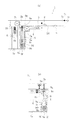
- FIGS. 1 to 3 are diagrams showing a schematic configuration of a floating flap gate of the present invention.
- reference numeral 1 denotes a floating flap gate of the present invention installed on a road surface rs of an opening provided in a breakwater or a tide wall, for example.
- the floating flap gate 1 uses the water pressure of the flowing water w as a fulcrum to support the rotating shaft 2c on the base end side 2a when the water w tries to flow into the living space or underground space from the ocean (or river).
- the front end side 2b of the door body 2 is swung upright to block the opening in a watertight state.
- the floating flap gate 1 of the present invention has one end of a wire rope 4 attached to the back surface 2d of the door body 2 in a lying state, as shown in FIG.
- the bracket 3 is provided on both sides of the rear surface 2d of the door body 2, for example, in the middle in the height direction of the door body 2.
- one end of a wire rope 4 is attached to these brackets 3.
- the other end of the wire rope 4 is drawn into an underground space 5 a formed on the distal end side 2 b of the door body 2 in the storage space 5 for storing the fallen door body 2.
- a counterweight 6 Inside the underground space 5a, for example, a counterweight 6, compression springs 10 provided on both sides of the upper surface of the counterweight 6, first and second constant pulleys 7a and 7b, and first and second movable pulleys.
- a pulley group consisting of 8a and 8b is arranged in association. Then, the other end of the drawn wire rope 4 is guided above the counterweight 6 through this pulley group, and fixed to the ceiling portion of the underground space 5a at the position, so that the width of the door body 2 is increased.
- a counterweight 6 having a slightly narrow width is suspended.
- the first fixed pulley 7a is in the retracted portion of the wire rope 4 in the underground space 5a
- the second fixed pulley 7b is in the ceiling portion of the underground space 5a above the suspension position of the counterweight 6.
- first movable pulley 8a is rotatably attached to the lower end of the push-up rod 9 that moves up and down between the first constant pulley 7a and the second constant pulley 7b.
- the second movable pulley 8 b is attached to the counterweight 6.
- the push-up rod 9 moves in the direction of the distal end 2b and the proximal end 2a of the door body 2 in a lying state, and the upper and lower guide rollers 9a, It is regulated by 9b. Further, the movement of the push-up rod 9 in the width direction of the door body 2 is regulated by the upper and lower side rollers 9c and 9d. Further, the vertical movement of the push-up rod 9 is restricted by an upper limit stopper 9e and a lower limit stopper 9f, and a push-up roller 9g is attached to the upper end.
- the floating-type flap gate 1 according to the present invention having the above-described effects exhibits the following effects when the door body 2 stands up and when the door body 2 falls down.
- the turning force in the lying direction acting on the door body 2 and the turning force in the standing direction acting on the door body 2 turn in the lying direction while balancing.
- the turning force acting on the door 2 at this time is the tension Ft generated on the wire rope 4 by the weight Fm of the door 2 and the counterweight 6.
- the turning force in the standing direction that acts on the door body 2 is the hydraulic pressure Fw that acts on the submerged portion of the back surface 2 d of the door body 2. Due to the fall of the door body 2, the turning force in the fall direction due to the weight Fm of the door body 2 is increased.
- the lodging action is decelerated by the turning force in the standing direction.
- the length in the height direction of the door body 2 is L
- the thickness of the door body 2 is D
- the position where the push-up rod 9 acts ascending force Is Lp
- the upper limit stroke St of the vertical movement of the push-up rod 9 can be obtained by the following equation (1).
- St (Lp ⁇ D ⁇ sin ⁇ ) tan ⁇ + D (1 ⁇ cos ⁇ ) (1)
- Fw Water pressure acting on the back surface 2d of the door body 2
- Lw Center-of-gravity distance of water pressure acting on the back surface 2d of the door body 2 (distance from the rotating shaft 2c of the door body 2)
- Fm Air weight of door body 2 Lm: Horizontal distance from the center of the rotation axis 2c of the door body 2 to the center of gravity ( ⁇ 1/2 ⁇ cos ⁇ )
- Ft Air weight of door body 2 Lm: Horizontal distance from the center of the rotation axis 2c of the door body 2 to the center of gravity ( ⁇ 1/2 ⁇ cos ⁇ )
- Ft Air weight of door body 2 Lm: Horizontal distance from the center of the rotation
- the door body 2 starts to stand up when the water depth h at which the door body 2 starts to rise is 2/3 to 4/5 of the thickness D of the door body 2 in the lying state.
- the push-up force Fp of the push-up rod 9 that can be obtained by the equation (4) is set. That is, the weight W of the counterweight 6 is set.
- the standing direction generated by the water pressure Fw acting on the back surface 2d of the door body 2 when the water depth h at which the door body 2 starts to rise is 2/3 to 4/5 of the thickness D of the door body 2 in the lying state.
- the weight W of the counterweight 6 is determined.
- the door body 2 of the floating flap gate 1 of the present invention is not limited to a long span, and may be a short span.
- the installation positions of the first and second constant pulleys 7a and 7b and the first and second movable pulleys 8a and 8b, the shape and layout of the counterweight 6, and the push-up rod 9 are increased as the counterweight 6 is raised and lowered. If it can raise / lower, it is not restricted to the installation position and layout of an Example.
- the number and layout of the compression springs 10 are not limited to those described in the embodiment as long as the compression spring 10 functions as a cushion at the limit of the standing of the door body 2. Moreover, if it has the same effect
- the member which supports the load at the time of standing is provided separately without supporting the load at the time of standing of the door body 2 only with the wire rope 4 like an Example, the required intensity
Landscapes
- Engineering & Computer Science (AREA)
- Structural Engineering (AREA)
- General Engineering & Computer Science (AREA)
- Civil Engineering (AREA)
- Architecture (AREA)
- Mechanical Engineering (AREA)
- Business, Economics & Management (AREA)
- Emergency Management (AREA)
- Environmental & Geological Engineering (AREA)
- Special Wing (AREA)
- Buildings Adapted To Withstand Abnormal External Influences (AREA)
Abstract
扉体の幅方向中間部に地上構造物を設けることができない径間が長い扉体の設置を可能とする。 水の流入時、基端側2aの回転軸2cを支点として扉体2の先端側2bが起立揺動する浮体式フラップゲート1である。倒伏状態の扉体2の裏面2dにワイヤロープ4の一端を固定する。倒伏した扉体2を格納する格納空間5の扉体2の先端部側に地下スペース5aを形成し、地下スペース5aの内部に、第1、第2の定滑車7a,7bと第1、第2の動滑車8a,8bを配置する。この滑車群を介して案内したワイヤロープ4の他端を地下スペース5aの天井部に固定する。第2の動滑車8bを取り付けたカウンタウエイト6の昇降により、第1の動滑車8aを取り付けたプッシュアップロッド9を昇降させ、起立初期の扉体2の先端側の押し上げと倒伏終期の急激な倒伏の抑制、ワイヤロープ4に作用する張力により、起立終期の衝撃吸収と倒伏初期の水位追従を行う。
Description
本発明は、開口の広い建物・地下空間、陸閘門・滑走路の端部或いは護岸・堤防のように、景観上、常時は嵩上げのできない或いは嵩上げをしたくない箇所に増水した水が流れ込まないように、扉体を浮上させて水の流入を阻止する浮体式フラップゲートに関するものである。
増水時に、増水した水が建物や地下空間に流れ込まないようにするため、例えば特許文献1,2には、流入しようとする水の浮力を利用して扉体を浮上させ、防波堤や防潮壁の開口部を遮断する浮体式フラップゲートが開示されている。
特許文献1,2で開示された浮体式フラップゲートは、扉体の開閉補助機構を備えている。この開閉補助機構は、流入初期に扉体の浮上動作が遅れて生活空間や地下空間へ越流することがなく、また、水位低下時にも倒伏がし難くならず、かつ急激に倒伏することもないようにするものである。
特許文献1,2で開示された扉体の前記開閉補助機構は、ロープの一端を扉体の先端部に、ロープの他端は定滑車を介してカウンタウエイト又はばねに取付けている。その際、扉体の起立又は倒伏途中でカウンタウエイトが最下点又はばねが自然長となるように前記定滑車を設置している。
ところで、特許文献1では、扉体の前記開閉補助機構は、倒伏した扉体の側部に設置された戸当りの内部に設けられている。また、特許文献2では、扉体の前記開閉補助機構は、倒伏した扉体の先端面両側のロープ取付け部と相対する位置に設けた収納体の内部に設けられている。
つまり、特許文献1,2で開示された扉体の前記開閉補助機構は、何れも扉体の両側部から扉体の開閉を補助するものである。この場合、扉体の幅(径間)が長くなると扉体の開閉を補助することが困難になる。
従って、特許文献1,2で開示された扉体の開閉補助機構を設置する場合、径間には限界があり、径間が長くなると扉体の幅方向中間部にも戸当りや収納体等の地上構造物を設ける必要がある。
以上の理由により、扉体の幅方向中間部に地上構造物を設けることができない、或いは扉体の幅方向中間部に地上構造物を設けたくない用途においては、特許文献1,2で開示された扉体の開閉補助機構では対応することができない。
本発明が解決しようとする問題点は、浮体式フラップゲートの扉体側部の地上構造物に設ける開閉補助機構の場合、扉体の幅方向中間部に地上構造物を設けることができない場合は対応することができないという点である。
本発明は、浮体式フラップゲートの扉体の開閉補助機構を、滑走路の端部のように径間が長く、その中間部に地上構造物を設けることができない場合であっても設置できるようにすることを目的としてなされたものである。
本発明は、増水時に、増水した水の流入を阻止するため、前記流入する水の方向に高さ方向の平面内で扉体の先端側が基端側の回転軸を支点とする起立揺動を可能とした浮体式フラップゲートであって、以下の構成の扉体の開閉補助機構を設けたことが最も主要な特徴である。
すなわち、本発明の扉体の開閉補助機構は、倒伏状態の扉体の裏面にロープの一端を固定し、ロープの他端を、倒伏した扉体を格納する格納空間の、前記扉体の先端部側に形成した地下スペースの天井部に固定する。そして、地下スペースの内部に第1,2の定滑車と第1,2の動滑車を配置し、この滑車群で前記ロープの他端を案内する。この構成により、前記ロープを案内する第2の動滑車を取り付けたカウンタウエイトの昇降により、第1の動滑車を取り付けたプッシュアップロッドを昇降させて起立初期の扉体の先端側の押し上げと倒伏終期の急激な倒伏の抑制を行う。また、前記ロープに作用する張力により、起立終期の衝撃吸収と倒伏初期の水位追従を行う。
上記の本発明では、扉体の開閉補助機構を、倒伏した扉体を格納する格納空間の、扉体の先端部側に形成した地下スペース内に設置する。従って、滑走路の端部のように径間が長く、その中間部に地上構造物を設けることができない場合であっても浮体式フラップゲートを設置することができる。
本発明では、扉体の開閉補助機構により、扉体の起立初期の起立補助、起立終期の衝撃吸収、倒伏初期の水位追従、倒伏終期の倒伏抑制が可能になる。従って、流入初期の越流防止や起立完了時の衝撃を緩和できると共に、倒伏初期には水位ヘの追従性が良くなり、倒伏完了前の急激な倒伏がなくなる。
また、本発明では、扉体の開閉補助機構を、倒伏した扉体を格納する格納空間の、扉体の先端部側に形成した地下スペース内に設置している。従って、径間が長い扉体の中間部に地上構造物を設けることができない場合であっても設置することができる。
本発明の目的は、径間が長い扉体の中間部に地上構造物を設けることができない場合であっても径間が長い扉体を設置できるようにすることである。そして、本発明は、前記目的を、扉体の開閉補助機構を、倒伏した扉体を格納する格納空間の、扉体の先端部側に形成した地下スペース内に設置することで実現した。
本発明を実施するための形態を、図1~図11を用いて詳細に説明する。
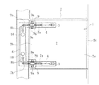
図1~図3は本発明の浮体式フラップゲートの概略構成を示した図である。
図1~図3は本発明の浮体式フラップゲートの概略構成を示した図である。
図1~図3において、1は例えば防波堤や防潮壁に設けた開口部の路面rsに設置される本発明の浮体式フラップゲートである。この浮体式フラップゲート1は、海洋(或いは河川)から生活空間や地下空間に水wが流入しようとする際、流入する水wの水圧を利用して、基端側2aの回転軸2cを支点として扉体2の先端側2bを起立揺動させて前記開口部を水密状態に遮断するものである。
本発明の浮体式フラップゲート1は、図1(a)に示すように、倒伏状態にある扉体2の裏面2dにワイヤロープ4の一端を取付けている。この扉体2の裏面2dへのワイヤロープ4の取付け例として、図1及び図2に示した例では、扉体2の裏面2dの例えば扉体2の高さ方向中間部の両側にブラケット3を取付け、これらブラケット3にワイヤロープ4の一端を取付けている。このワイヤロープ4の他端は、倒伏した扉体2を格納する格納空間5の、扉体2の先端側2bに形成した地下スペース5aに引き込まれている。
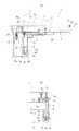
前記地下スペース5aの内部には、例えばカウンタウエイト6と、カウンタウエイト6の上面の両側に設けた圧縮ばね10と、第1、第2の定滑車7a,7b及び第1、第2の動滑車8a,8bからなる滑車群が関連配置されている。そして、前記引き込まれたワイヤロープ4の他端を、この滑車群を介してカウンタウエイト6の上方に案内し、当該位置の地下スペース5aの天井部に固定することで、扉体2の幅より若干狭い幅のカウンタウエイト6を吊り下げている。
前記滑車群のうち第1の定滑車7aは、地下スペース5aのワイヤロープ4の引込み部に、第2の定滑車7bは、カウンタウエイト6の吊下げ位置上部の地下スペース5aの天井部に、それぞれ設けている。
一方、第1の動滑車8aは、前記第1の定滑車7aと第2の定滑車7bの間で昇降移動するプッシュアップロッド9の下端に回転自在に取り付けている。また、第2の動滑車8bは、カウンタウエイト6に取り付けている。
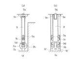
なお、前記プッシュアップロッド9の昇降移動時、倒伏状態の扉体2の先端側2bの方向及び基端側2aの方向への前記プッシュアップロッド9の移動は、上部と下部のガイドローラ9a,9bによって規制されている。また、扉体2の幅方向への前記プッシュアップロッド9の移動は、上下のサイドローラ9c、9dによって規制されている。また、このプッシュアップロッド9の上下方向の昇降移動は、上限ストッパ9eと下限ストッパ9fによって規制され、上端には押し上げローラ9gを取り付けている。
地下スペース5aの内部に、第1、第2の定滑車7a,7b、第1、第2の動滑車8a,8b、カウンタウエイト6、プッシュアップロッド9を関連配置した扉体2の開閉補助機構を備えた本発明の浮体式フラップゲート1は、扉体2の起立時、及び扉体2の倒伏時は、以下に説明する作用を奏する。
(扉体2の起立初期:図4)
浸水が所定の水位に達し、扉体2に作用する起立方向の旋回力が扉体2の重量Fmによる倒伏方向の旋回力より大きくなると扉体2は浮上を開始する。この時の扉体2に作用する起立方向の旋回力は、扉体2に作用する浮力と、カウンタウエイト6により作用しているプッシュアップロッド9の押し上げ力を加えたものである。
浸水が所定の水位に達し、扉体2に作用する起立方向の旋回力が扉体2の重量Fmによる倒伏方向の旋回力より大きくなると扉体2は浮上を開始する。この時の扉体2に作用する起立方向の旋回力は、扉体2に作用する浮力と、カウンタウエイト6により作用しているプッシュアップロッド9の押し上げ力を加えたものである。
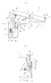
(扉体2の起立中期:図5)
プッシュアップロッド9が上昇限に到達した後は、扉体2に作用する起立方向の旋回力が扉体2に作用する倒伏方向の旋回力より大きくなって、扉体2は起立方向に旋回して起立する。この時の扉体2に作用する起立方向の旋回力は、扉体2の裏面2dの没水部に作用する水圧Fwである。また、扉体2に作用する倒伏方向の旋回力は、扉体2の重量Fmとカウンタウエイト6によってワイヤロープ4に発生する張力Ftである。
プッシュアップロッド9が上昇限に到達した後は、扉体2に作用する起立方向の旋回力が扉体2に作用する倒伏方向の旋回力より大きくなって、扉体2は起立方向に旋回して起立する。この時の扉体2に作用する起立方向の旋回力は、扉体2の裏面2dの没水部に作用する水圧Fwである。また、扉体2に作用する倒伏方向の旋回力は、扉体2の重量Fmとカウンタウエイト6によってワイヤロープ4に発生する張力Ftである。
(扉体2の起立終期:図6)
扉体2が起立限の近くまで起立した時には、カウンタウエイト6は上昇限位置近傍まで移動しており、圧縮ばね10が圧縮される。従って、カウンタウエイト6の重量Wと圧縮ばね10の圧縮力によってワイヤロープ4に発生する張力Ftが、扉体2の起立方向の旋回の制動力として倒伏方向に作用する。
扉体2が起立限の近くまで起立した時には、カウンタウエイト6は上昇限位置近傍まで移動しており、圧縮ばね10が圧縮される。従って、カウンタウエイト6の重量Wと圧縮ばね10の圧縮力によってワイヤロープ4に発生する張力Ftが、扉体2の起立方向の旋回の制動力として倒伏方向に作用する。
(扉体2の倒伏初期:図7)
水位が低下し、扉体2に作用する起立方向の旋回力が減少すると、扉体2に作用する倒伏方向の旋回力と釣り合う位置まで扉体2は倒伏方向に旋回する。この時の扉体2に作用する起立方向の旋回力は、扉体2の裏面2dの没水部に作用する水圧Fwである。また、扉体2に作用する倒伏方向の旋回力は、扉体2の重量Fmとカウンタウエイト6によってワイヤロープ4に発生する張力Ftである。なお、起立上限付近では、ワイヤロープ4に発生する張力Ftには圧縮ばね力も加わる。
水位が低下し、扉体2に作用する起立方向の旋回力が減少すると、扉体2に作用する倒伏方向の旋回力と釣り合う位置まで扉体2は倒伏方向に旋回する。この時の扉体2に作用する起立方向の旋回力は、扉体2の裏面2dの没水部に作用する水圧Fwである。また、扉体2に作用する倒伏方向の旋回力は、扉体2の重量Fmとカウンタウエイト6によってワイヤロープ4に発生する張力Ftである。なお、起立上限付近では、ワイヤロープ4に発生する張力Ftには圧縮ばね力も加わる。
(扉体2の倒伏中期:図8)
扉体2に作用する倒伏方向の旋回力と扉体2に作用する起立方向の旋回力がバランスしながら倒伏方向に旋回する。この時の扉体2に作用する倒伏方向の旋回力は、扉体2の重量Fmとカウンタウエイト6によってワイヤロープ4に発生する張力Ftである。また、扉体2に作用する起立方向の旋回力は、扉体2の裏面2dの没水部に作用する水圧Fwである。扉体2の倒伏により、扉体2の重量Fmによる倒伏方向の旋回力が増大するが、扉体2の裏面2dにプッシュアップロッド9が当接した後は、プッシュアップロッド9の押し上げ力による起立方向の旋回力により倒伏動作は減速する。
扉体2に作用する倒伏方向の旋回力と扉体2に作用する起立方向の旋回力がバランスしながら倒伏方向に旋回する。この時の扉体2に作用する倒伏方向の旋回力は、扉体2の重量Fmとカウンタウエイト6によってワイヤロープ4に発生する張力Ftである。また、扉体2に作用する起立方向の旋回力は、扉体2の裏面2dの没水部に作用する水圧Fwである。扉体2の倒伏により、扉体2の重量Fmによる倒伏方向の旋回力が増大するが、扉体2の裏面2dにプッシュアップロッド9が当接した後は、プッシュアップロッド9の押し上げ力による起立方向の旋回力により倒伏動作は減速する。
(扉体2の倒伏終期:図9)
水位が低下し、扉体2の裏面2dの没水部に作用する水圧Fwによる浮上力がなくなると、扉体2の重量Fmによる倒伏方向の旋回力により扉体2は格納空間5に着床する。この時、カウンタウエイト6によるプッシュアップロッド9の押し上げ力は、扉体2の重量Fmによる倒伏方向の旋回力より大きくなるほどの起立方向の旋回力はないが、プッシュアップロッド9の押し上げ力により着床時の衝撃が緩和される。
水位が低下し、扉体2の裏面2dの没水部に作用する水圧Fwによる浮上力がなくなると、扉体2の重量Fmによる倒伏方向の旋回力により扉体2は格納空間5に着床する。この時、カウンタウエイト6によるプッシュアップロッド9の押し上げ力は、扉体2の重量Fmによる倒伏方向の旋回力より大きくなるほどの起立方向の旋回力はないが、プッシュアップロッド9の押し上げ力により着床時の衝撃が緩和される。
(プッシュアップロッド9の昇降移動の上限ストロークStの設定:図10)
起立初期、倒伏終期における上記作用のため、プッシュアップロッド9の昇降移動の上限ストロークSt、すなわち当該上限ストロークStとなる扉体2の起立角度θは、以下のように設定する。
起立初期、倒伏終期における上記作用のため、プッシュアップロッド9の昇降移動の上限ストロークSt、すなわち当該上限ストロークStとなる扉体2の起立角度θは、以下のように設定する。
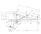
図10に示すように、扉体2の高さ方向の長さをL、扉体2の厚さをD、プッシュアップロッド9による上昇力の作用位置(扉体2の回転軸2cからの距離)をLpとした場合、プッシュアップロッド9の昇降移動の上限ストロークStは、下記(1)式で求めることができる。
St=(Lp-D・sinθ)tanθ+D(1-cosθ)…(1)
St=(Lp-D・sinθ)tanθ+D(1-cosθ)…(1)
水深hがプッシュアップロッド9の上限ストロークStにおける扉体2の先端標高H(=L・sinθ+D)の4/5の時に、下記(2)式のように、扉体2の裏面2dに作用する水圧Fwにより発生する起立方向の旋回力(=Fw×Lw)が、扉体2の重量Fm及びワイヤロープ4の張力Ftにより発生する倒伏方向の旋回力(=Fm×Lm+Ft×Lt)よりも大きくなるようにする。
Fw×Lw(=Ph1×L×B×L/2+1/2・(Ph2-Ph1)×L×B×L/3)
≧Fm×Lm+Ft×Lt…(2)
但し、Fw:扉体2の裏面2dに作用する水圧
Lw:扉体2の裏面2dに作用する水圧力の重心距離
(扉体2の回転軸2cからの距離)
Ph1:扉体2の裏面2dの先端の水深h1(=D・cosθ-H/5)の作用水圧
Ph2:扉体2の裏面2dの基端の水深h2(=h1+L・sinθ)の作用水圧
Fm:扉体2の空中重量
Lm:扉体2の回転軸2cの中心から重心までの水平距離(≒1/2・cosθ)
Ft:ワイヤロープ4の張力(=W/2×α、α:滑車などの機械効率)
Lt:ワイヤロープ4の引張り位置までの距離
(扉体2の回転軸2cの中心から引張方向への垂直距離)
B:扉体2の幅
≧Fm×Lm+Ft×Lt…(2)
但し、Fw:扉体2の裏面2dに作用する水圧
Lw:扉体2の裏面2dに作用する水圧力の重心距離
(扉体2の回転軸2cからの距離)
Ph1:扉体2の裏面2dの先端の水深h1(=D・cosθ-H/5)の作用水圧
Ph2:扉体2の裏面2dの基端の水深h2(=h1+L・sinθ)の作用水圧
Fm:扉体2の空中重量
Lm:扉体2の回転軸2cの中心から重心までの水平距離(≒1/2・cosθ)
Ft:ワイヤロープ4の張力(=W/2×α、α:滑車などの機械効率)
Lt:ワイヤロープ4の引張り位置までの距離
(扉体2の回転軸2cの中心から引張方向への垂直距離)
B:扉体2の幅
(カウンタウエイト6の重量Wの設定:図11)
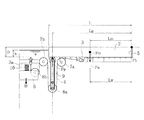
図11に示すように、扉体2が浮上を開始する水深をhとした場合、扉体2が浮上を開始する水深hにおける扉体に作用する浮力Fwは、下記(3)式で求めることができる。
図11に示すように、扉体2が浮上を開始する水深をhとした場合、扉体2が浮上を開始する水深hにおける扉体に作用する浮力Fwは、下記(3)式で求めることができる。
Fw=Ph×L×B…(3)
倒伏時に上記作用を奏するため、扉体2が浮上を開始する水深hが倒伏状態の扉体2の厚さDの2/3~4/5の時に扉体2の起立が開始するよう、下記(4)式で求めることができるプッシュアップロッド9の押し上げ力Fpを設定する。すなわちカウンタウエイト6の重量Wを設定する。
Fp=W×α-w2…(4)
但し、w2:プッシュアップロッド9の重量
但し、w2:プッシュアップロッド9の重量
そして、扉体2が浮上を開始する水深hが倒伏状態の扉体2の厚さDの2/3~4/5の時の扉体2の裏面2dに作用する水圧Fwにより発生する起立方向の旋回力及びプッシュアップロッド9の押し上げ力Fpによる起立方向の旋回力(=Fw×Lw+Fp×Lp)と、扉体2の重量Fmにより発生する倒伏方向の旋回力(=Fm×Lm)が等しくなるように、カウンタウエイト6の重量Wを決定する。
本発明は、前記の例に限るものではなく、各請求項に記載の技術的思想の範疇であれば、適宜実施の形態を変更しても良いことは言うまでもない。
例えば、本発明の浮体式フラップゲート1の扉体2は径間の長いものに限らず、径間の短いものであってもよい。
また、第1、第2の定滑車7a,7bや第1、第2の動滑車8a,8bの設置位置やカウンタウエイト6の形状やレイアウトは、カウンタウエイト6の昇降に伴ってプッシュアップロッド9を昇降できるものであれば、実施例の設置位置やレイアウトに限らない。
また、圧縮ばね10は扉体2の起立限でクッションの役割を果たすものであれば、設置する個数やレイアウトは実施例で説明したものに限らない。また、同様の作用を奏するものであれば、圧縮ばね10に限らない。また、圧縮ばね10は設置しなくてもよい。
また、実施例のように、扉体2の起立時の荷重をワイヤロープ4だけで支持せず、起立時の荷重を支持する部材を別途設ける場合は、ワイヤロープ4の必要強度を下げることができる。
1 浮体式フラップゲート
2 扉体
2a 基端側
2b 先端側
2c 回転軸
2d 裏面
4 ワイヤロープ
5 格納空間
5a 地下スペース
6 カウンタウエイト
7a 第1の定滑車
7b 第2の定滑車
8a 第1の動滑車
8b 第2の動滑車
9 プッシュアップロッド
10 圧縮ばね
2 扉体
2a 基端側
2b 先端側
2c 回転軸
2d 裏面
4 ワイヤロープ
5 格納空間
5a 地下スペース
6 カウンタウエイト
7a 第1の定滑車
7b 第2の定滑車
8a 第1の動滑車
8b 第2の動滑車
9 プッシュアップロッド
10 圧縮ばね
Claims (3)
- 増水時に、増水した水の流入を阻止するため、前記流入する水の方向に高さ方向の平面内で扉体の先端側が基端側の回転軸を支点とする起立揺動が可能なように構成した浮体式フラップゲートであって、
倒伏状態の扉体の裏面に一端を固定したロープの他端を、倒伏した扉体を格納する格納空間の、前記扉体の先端部側に形成した地下スペースの内部に配置した第1,2の定滑車と第1,2の動滑車を介して案内して前記地下スペースの天井部に固定し、前記ロープを案内する第2の動滑車を取り付けたカウンタウエイトの昇降により、第1の動滑車を取り付けたプッシュアップロッドを昇降させて起立初期の扉体の先端側の押し上げと倒伏終期の急激な倒伏の抑制を行うとともに、前記ロープに作用する張力により、起立終期の衝撃吸収と倒伏初期の水位追従を行う扉体の開閉補助機構を有することを特徴とする浮体式フラップゲート。 - 前記第1,2の定滑車のうち、第1の定滑車は、前記地下スペースへの前記ロープの引込み部に設け、第2の定滑車は、前記カウンタウエイトの吊下げ位置に設けることを特徴とする請求の範囲第1項に記載の浮体式フラップゲート。
- 前記カウンタウエイトの上面に圧縮ばねを設けたことを特徴とする請求の範囲第1項又は第2項に記載の浮体式フラップゲート。
Applications Claiming Priority (2)
| Application Number | Priority Date | Filing Date | Title |
|---|---|---|---|
| JP2015-091293 | 2015-04-28 | ||
| JP2015091293A JP6461699B2 (ja) | 2015-04-28 | 2015-04-28 | 浮体式フラップゲート |
Publications (1)
| Publication Number | Publication Date |
|---|---|
| WO2016174919A1 true WO2016174919A1 (ja) | 2016-11-03 |
Family
ID=57199745
Family Applications (1)
| Application Number | Title | Priority Date | Filing Date |
|---|---|---|---|
| PCT/JP2016/056444 Ceased WO2016174919A1 (ja) | 2015-04-28 | 2016-03-02 | 浮体式フラップゲート |
Country Status (3)
| Country | Link |
|---|---|
| JP (1) | JP6461699B2 (ja) |
| TW (1) | TW201638433A (ja) |
| WO (1) | WO2016174919A1 (ja) |
Cited By (1)
| Publication number | Priority date | Publication date | Assignee | Title |
|---|---|---|---|---|
| CN113152392A (zh) * | 2021-04-29 | 2021-07-23 | 李圣 | 一种水利工程施工用自动启闭式闸门 |
Families Citing this family (3)
| Publication number | Priority date | Publication date | Assignee | Title |
|---|---|---|---|---|
| US11098458B2 (en) | 2017-03-24 | 2021-08-24 | Hitachi Zosen Corporation | Flap gate |
| JP7161984B2 (ja) * | 2019-10-31 | 2022-10-27 | 日立造船株式会社 | 起伏ゲート式防波堤の係留装置 |
| CN111101490B (zh) * | 2020-03-02 | 2025-08-12 | 山东农业大学 | 双叶同向双开水力自控闸门及其使用方法 |
Citations (5)
| Publication number | Priority date | Publication date | Assignee | Title |
|---|---|---|---|---|
| JPH01176134U (ja) * | 1988-05-31 | 1989-12-15 | ||
| JP2010133095A (ja) * | 2008-12-02 | 2010-06-17 | Hitachi Zosen Corp | 起伏ゲート式防波堤の扉体係留装置 |
| WO2011065086A1 (ja) * | 2009-11-24 | 2011-06-03 | 日立造船株式会社 | 起伏ゲート式防波堤の係留装置 |
| JP2012241449A (ja) * | 2011-05-20 | 2012-12-10 | Hitachi Zosen Corp | 浮体式フラップゲート |
| JP2014118774A (ja) * | 2012-12-18 | 2014-06-30 | Hitachi Zosen Corp | 浮体式フラップゲート |
-
2015
- 2015-04-28 JP JP2015091293A patent/JP6461699B2/ja active Active
-
2016
- 2016-03-02 WO PCT/JP2016/056444 patent/WO2016174919A1/ja not_active Ceased
- 2016-04-27 TW TW105113166A patent/TW201638433A/zh unknown
Patent Citations (5)
| Publication number | Priority date | Publication date | Assignee | Title |
|---|---|---|---|---|
| JPH01176134U (ja) * | 1988-05-31 | 1989-12-15 | ||
| JP2010133095A (ja) * | 2008-12-02 | 2010-06-17 | Hitachi Zosen Corp | 起伏ゲート式防波堤の扉体係留装置 |
| WO2011065086A1 (ja) * | 2009-11-24 | 2011-06-03 | 日立造船株式会社 | 起伏ゲート式防波堤の係留装置 |
| JP2012241449A (ja) * | 2011-05-20 | 2012-12-10 | Hitachi Zosen Corp | 浮体式フラップゲート |
| JP2014118774A (ja) * | 2012-12-18 | 2014-06-30 | Hitachi Zosen Corp | 浮体式フラップゲート |
Cited By (1)
| Publication number | Priority date | Publication date | Assignee | Title |
|---|---|---|---|---|
| CN113152392A (zh) * | 2021-04-29 | 2021-07-23 | 李圣 | 一种水利工程施工用自动启闭式闸门 |
Also Published As
| Publication number | Publication date |
|---|---|
| TW201638433A (zh) | 2016-11-01 |
| JP6461699B2 (ja) | 2019-01-30 |
| JP2016205077A (ja) | 2016-12-08 |
Similar Documents
| Publication | Publication Date | Title |
|---|---|---|
| KR101680172B1 (ko) | 부체식 플랩 게이트 | |
| EP2971366B1 (en) | Flood guard barrier lifting system | |
| KR101619092B1 (ko) | 부체식 플랩 게이트 | |
| JP6434874B2 (ja) | 浮体式フラップゲート | |
| WO2016174919A1 (ja) | 浮体式フラップゲート | |
| TWI593857B (zh) | 浮體式舌瓣閘門 | |
| CN112343002A (zh) | 防洪装置及防洪方法 | |
| JP5416292B1 (ja) | フロート式止水扉 | |
| CN108026708B (zh) | 水闸 | |
| JP2013253381A (ja) | 浮体式フラップゲート | |
| JP6117280B2 (ja) | 浮体式フラップゲート | |
| CN206117567U (zh) | 适用于高水位差的浮动式水上光伏锚固装置 | |
| CN205501936U (zh) | 一种河道中的拦阻设施 | |
| JP6438555B2 (ja) | 浮体式フラップゲート | |
| JP5948206B2 (ja) | 浮体式フラップゲート | |
| JP2018178400A (ja) | 起伏ゲート | |
| WO2017163691A1 (ja) | 浮体式フラップゲート設備 | |
| JP2015094163A (ja) | 浮体式避難通路、浮体式避難通路網 | |
| JP2015209714A (ja) | 浮体式フラップゲート | |
| JP2012246721A (ja) | 高さ可変な津波対応建造物 | |
| CN108104559A (zh) | 一种框架式自上浮防水淹停车位和停车区 | |
| JP2019019670A (ja) | 浮体式フラップゲート | |
| EP2514878A1 (en) | Jack-up offshore platform and method for reducing lateral oscillating movements thereof |
Legal Events
| Date | Code | Title | Description |
|---|---|---|---|
| 121 | Ep: the epo has been informed by wipo that ep was designated in this application |
Ref document number: 16786196 Country of ref document: EP Kind code of ref document: A1 |
|
| NENP | Non-entry into the national phase |
Ref country code: DE |
|
| 122 | Ep: pct application non-entry in european phase |
Ref document number: 16786196 Country of ref document: EP Kind code of ref document: A1 |