WO2016174913A1 - ディップコーティング装置およびコーティングされた部材の製造方法 - Google Patents
ディップコーティング装置およびコーティングされた部材の製造方法 Download PDFInfo
- Publication number
- WO2016174913A1 WO2016174913A1 PCT/JP2016/055935 JP2016055935W WO2016174913A1 WO 2016174913 A1 WO2016174913 A1 WO 2016174913A1 JP 2016055935 W JP2016055935 W JP 2016055935W WO 2016174913 A1 WO2016174913 A1 WO 2016174913A1
- Authority
- WO
- WIPO (PCT)
- Prior art keywords
- coated
- fixing
- storage tank
- dip coating
- fixing portion
- Prior art date
- Legal status (The legal status is an assumption and is not a legal conclusion. Google has not performed a legal analysis and makes no representation as to the accuracy of the status listed.)
- Ceased
Links
Images


Classifications
-
- B—PERFORMING OPERATIONS; TRANSPORTING
- B05—SPRAYING OR ATOMISING IN GENERAL; APPLYING FLUENT MATERIALS TO SURFACES, IN GENERAL
- B05D—PROCESSES FOR APPLYING FLUENT MATERIALS TO SURFACES, IN GENERAL
- B05D1/00—Processes for applying liquids or other fluent materials
- B05D1/18—Processes for applying liquids or other fluent materials performed by dipping
-
- B—PERFORMING OPERATIONS; TRANSPORTING
- B05—SPRAYING OR ATOMISING IN GENERAL; APPLYING FLUENT MATERIALS TO SURFACES, IN GENERAL
- B05C—APPARATUS FOR APPLYING FLUENT MATERIALS TO SURFACES, IN GENERAL
- B05C13/00—Means for manipulating or holding work, e.g. for separate articles
- B05C13/02—Means for manipulating or holding work, e.g. for separate articles for particular articles
- B05C13/025—Means for manipulating or holding work, e.g. for separate articles for particular articles relatively small cylindrical objects, e.g. cans, bottles
-
- B—PERFORMING OPERATIONS; TRANSPORTING
- B05—SPRAYING OR ATOMISING IN GENERAL; APPLYING FLUENT MATERIALS TO SURFACES, IN GENERAL
- B05C—APPARATUS FOR APPLYING FLUENT MATERIALS TO SURFACES, IN GENERAL
- B05C3/00—Apparatus in which the work is brought into contact with a bulk quantity of liquid or other fluent material
- B05C3/02—Apparatus in which the work is brought into contact with a bulk quantity of liquid or other fluent material the work being immersed in the liquid or other fluent material
- B05C3/09—Apparatus in which the work is brought into contact with a bulk quantity of liquid or other fluent material the work being immersed in the liquid or other fluent material for treating separate articles
-
- B—PERFORMING OPERATIONS; TRANSPORTING
- B05—SPRAYING OR ATOMISING IN GENERAL; APPLYING FLUENT MATERIALS TO SURFACES, IN GENERAL
- B05D—PROCESSES FOR APPLYING FLUENT MATERIALS TO SURFACES, IN GENERAL
- B05D1/00—Processes for applying liquids or other fluent materials
- B05D1/36—Successively applying liquids or other fluent materials, e.g. without intermediate treatment
-
- B—PERFORMING OPERATIONS; TRANSPORTING
- B05—SPRAYING OR ATOMISING IN GENERAL; APPLYING FLUENT MATERIALS TO SURFACES, IN GENERAL
- B05D—PROCESSES FOR APPLYING FLUENT MATERIALS TO SURFACES, IN GENERAL
- B05D1/00—Processes for applying liquids or other fluent materials
- B05D1/40—Distributing applied liquids or other fluent materials by members moving relatively to surface
- B05D1/42—Distributing applied liquids or other fluent materials by members moving relatively to surface by non-rotary members
-
- A—HUMAN NECESSITIES
- A61—MEDICAL OR VETERINARY SCIENCE; HYGIENE
- A61M—DEVICES FOR INTRODUCING MEDIA INTO, OR ONTO, THE BODY; DEVICES FOR TRANSDUCING BODY MEDIA OR FOR TAKING MEDIA FROM THE BODY; DEVICES FOR PRODUCING OR ENDING SLEEP OR STUPOR
- A61M25/00—Catheters; Hollow probes
- A61M25/0009—Making of catheters or other medical or surgical tubes
-
- A—HUMAN NECESSITIES
- A61—MEDICAL OR VETERINARY SCIENCE; HYGIENE
- A61M—DEVICES FOR INTRODUCING MEDIA INTO, OR ONTO, THE BODY; DEVICES FOR TRANSDUCING BODY MEDIA OR FOR TAKING MEDIA FROM THE BODY; DEVICES FOR PRODUCING OR ENDING SLEEP OR STUPOR
- A61M25/00—Catheters; Hollow probes
- A61M25/10—Balloon catheters
- A61M25/1027—Making of balloon catheters
-
- B—PERFORMING OPERATIONS; TRANSPORTING
- B05—SPRAYING OR ATOMISING IN GENERAL; APPLYING FLUENT MATERIALS TO SURFACES, IN GENERAL
- B05D—PROCESSES FOR APPLYING FLUENT MATERIALS TO SURFACES, IN GENERAL
- B05D3/00—Pretreatment of surfaces to which liquids or other fluent materials are to be applied; After-treatment of applied coatings, e.g. intermediate treating of an applied coating preparatory to subsequent applications of liquids or other fluent materials
- B05D3/04—Pretreatment of surfaces to which liquids or other fluent materials are to be applied; After-treatment of applied coatings, e.g. intermediate treating of an applied coating preparatory to subsequent applications of liquids or other fluent materials by exposure to gases
- B05D3/0486—Operating the coating or treatment in a controlled atmosphere
Definitions
- the present invention relates to a dip coating apparatus capable of applying a coating material and a method for manufacturing a member in which a coating material is coated on a member to be coated.
- each application method is as follows: application efficiency (dosage (g) / actual application amount (g) to the site where application is required), area productivity, application speed, coating uniformity, waste generation amount , And can be compared and evaluated by indicators such as cost.
- Dip coating is a method in which a member to be coated is immersed in a tank in which a liquid coating material is stored and pulled up. With dip coating, the coating material can be uniformly applied to the coated member, coating efficiency and area productivity are high, foreign matter is less likely to enter the coating material than brush coating, and nozzle clogging such as spray coating is less likely to occur. Is often used.
- Patent Document 1 describes a coating apparatus for applying a coating liquid to the outer surface of a glass container.
- the coating apparatus grips and transports a dip tank and a glass container so as to rotate freely. It has a conveyor and a rotation imparting section for rotating the glass container in contact with the outer peripheral surface of the roller section of the conveyor.
- Patent Document 2 after applying only a half range of a cylindrical metal part, the other half range is applied so that the coating material is not attached to the jig supporting the cylindrical metal part.
- a coating material application method and applicator that can be described are described.
- a conventionally used dip coating apparatus includes, for example, a comb-like fixing member, a support member that engages with the tip of the fixing member, and a storage that stores the application material. Has a tank.
- a comb-like fixing member for example, a comb-like fixing member, a support member that engages with the tip of the fixing member, and a storage that stores the application material. Has a tank.
- the coating material is applied to the tubular body by immersing in a storage tank in which is stored.
- the member to be coated moves in the coating material (coating liquid), thereby causing another member or dip to be coated.
- Application failure may occur in contact with the inner wall of the tank.
- the coating material coating method and the coating apparatus of Patent Document 2 are difficult to apply when the member to be coated is a tubular body having a small outer diameter, and requires two coating operations for each member to be coated. It is difficult to increase. Further, since the coating operation is divided into two times, there is a possibility that unevenness occurs in the thickness of the coating film near the boundary between the two coating ranges.
- the conventional dip coating apparatus needs to engage and release the comb-shaped fixing member and the support member before and after immersing the tubular body in the coating material, there is room for improvement in work efficiency.
- the coating material adheres not only to the tubular body that is the member to be coated but also to the supporting member that does not originally require coating for every dipping operation of the tubular body, there is a concern that the coating efficiency may be reduced.
- the present invention has been made in view of the above circumstances, and its purpose is to minimize the adhesion of the coating material to the member that fixes the member to be coated, and to easily apply to the member to be coated.
- Another object of the present invention is to provide a dip coating apparatus that can be used, and a method for producing a coated member obtained by dip coating a coating material on a member to be coated.
- the dip coating apparatus of the present invention capable of achieving the above object is a device for coating a coated member with a coating material, a storage tank for storing the coating material, a first fixing portion for holding the coated member, It is provided directly or indirectly on the wall portion of the storage tank, and has a gist in that it has a second fixing portion that acts as a magnetic attraction with the first fixing portion.
- the dip coating apparatus of the present invention has a magnetic attractive force acting between a first fixing portion that holds a member to be coated and a second fixing portion that is provided on the wall of the storage tank, thereby The application member is fixed in a state of being drawn to the second fixing portion.
- the dip coating apparatus of the present invention even when the member to be coated receives buoyancy in the coating material in the storage tank, the first fixing portion is fixed to the second fixing portion while holding the member to be coated. In order to maintain, a to-be-coated member is hard to move within a storage tank. Moreover, since the dip coating apparatus of this invention can suppress that a coating material adheres to the supporting member engaged with a comb-shaped fixing member, for example for every immersion operation of a to-be-coated member like the conventional dip coating apparatus. The use efficiency of the coating material is increased.
- the dip coating apparatus of the present invention is a dip coating apparatus that coats a coating material on a member to be coated, the storage tank storing the coating material, the first fixing member holding the coating member, and the storage tank.
- the second fixing member may be provided directly or indirectly on the wall of the first fixing member, and a magnetic attractive force may be exerted between the first fixing member and the first fixing member. That is, the first fixing part and the second fixing part may be fixing members. That is, the first fixing portion may be provided on the first fixing member, and the second fixing portion may be provided on the second fixing member.
- the storage tank and the second fixing portion may be integrated. Therefore, since magnetic attraction works between the 1st fixed part and a storage tank, the structure of an apparatus can be simplified.
- the storage tank has an inner diameter of the first cross section that is parallel to the liquid surface of the coating material and close to the liquid surface, and is larger than the inner diameter of the second cross section on the bottom wall side than the first cross section. It is preferable. Thereby, the area of the opening part of the storage tank for immersing a to-be-coated member in a coating material, or pulling up a to-be-coated member out of a coating material can be taken. As a result, in the dip coating apparatus of the present invention, the separation distance between the member to be coated and the side wall can be increased, so that the member to be coated does not easily come into contact with the side wall. For this reason, generation
- the dip coating apparatus of the present invention it is preferable that at least a part of the side wall of the storage tank is inclined with respect to a direction perpendicular to the liquid surface of the coating material. If the side wall of the storage tank is inclined, the area of the opening of the storage tank for immersing the member to be coated in the coating material or pulling up the member to be coated from the coating material can be increased. As a result, in the dip coating apparatus of the present invention, the separation distance between the member to be coated and the side wall can be increased, so that the member to be coated does not easily come into contact with the side wall. Thereby, generation
- the first fixing portion has a rod shape. Thereby, when an application member is a tubular body, a bending of an application member can be prevented and it can fix. Moreover, it is preferable that the first fixing member has a rod shape, and an outer diameter at one end is larger than an outer diameter at the other end. Thereby, even if the first fixing member approaches the side wall, one end portion having a relatively large outer diameter comes into contact with the side wall of the storage tank first, and a certain distance between the coated member and the side wall is secured. Can do. For this reason, it becomes difficult for the member to be coated to come into contact with the side wall, and occurrence of poor coating due to contact between the member to be coated and the side wall can be suppressed.
- the first fixing portion has a portion that protrudes toward the side wall of the storage tank.
- a thick part is provided on the side wall of the storage tank.
- the strength of the magnetic attractive force acting between the first fixed portion and the second fixed portion can be weakened in the thick portion of the side wall of the storage tank, so that the first fixed portion and the second fixed portion are separated from each other. It can carry out smoothly and it becomes easy to take out a to-be-coated member and a 1st fixing
- the thick portion is preferably formed so as to increase in thickness from the lower side to the upper side of the storage tank in the direction perpendicular to the liquid level of the coating material.
- the side wall of the storage tank has a portion protruding to the inside of the storage tank.
- At least one of the first fixed portion and the second fixed portion has a magnet. If at least one of the first fixed part and the second fixed part has a magnet, a magnetic attractive force can be generated between the first fixed part and the second fixed part.
- the magnet is preferably an electromagnet.
- the strength of the magnetic attractive force can be adjusted.
- the dip coating apparatus of the present invention has a buffer member that acts on the side wall of the storage tank so that the magnetic repulsion works with the first fixing portion.
- fixed part contacts a storage tank can be reduced.
- a plurality of parallel first fixing portions respectively hold a plurality of parallel coated members.
- a coating material can be apply
- the member to be coated is preferably a medical tubular body.
- the dip coating apparatus of the present invention can be preferably used even if the medical tubular body is a medical catheter. Since the dip coating apparatus of the present invention can easily coat the member to be coated, the productivity of the medical tubular body and the medical catheter can be increased. Furthermore, the dip coating apparatus of the present invention can be preferably used even if the medical catheter is a balloon catheter. This is because the dip coating apparatus of the present invention can be suitably used even when the member to be coated is a tubular body having a large buoyancy.
- the present invention is preferably a medical tubular body manufactured by the dip coating apparatus. Since the medical tubular body manufactured by the dip coating apparatus is coated with the coating material uniformly, the function of the coating material is sufficiently exhibited, and a protective effect of the tubular body by the coating film can be expected.
- the present invention is a method for producing a coated member obtained by dip-coating a coating material on a member to be coated, the step of fixing the member to be coated to a first fixing portion, and the member to be coated as a coating material. And a second fixing that can generate a magnetic attraction between the first fixing part and the first fixing part provided directly or indirectly on the wall of the storage tank.
- a step of bringing the portion close to the portion, a step of releasing the proximity of the first fixing portion and the second fixing portion, and a step of pulling up the portion to be coated from the storage tank in which the coating material is stored. Has a gist.
- the coated member manufacturing method of the present invention generates a magnetic attractive force between the first fixing portion for fixing the member to be coated and the first fixing portion which is directly or indirectly provided on the wall of the storage tank. Since it includes the step of approaching the possible second fixing portion, the member to be coated fixed to the first fixing portion is drawn to the second fixing portion and fixed in the storage tank. Therefore, even if the member to be coated is susceptible to buoyancy, the first fixing portion attracts the second fixing portion in a state where the member to be coated is fixed, and thus the member to be coated is difficult to move in the storage tank.
- the coating material adheres to a support member that engages with, for example, a comb-shaped fixing member every time the member to be coated is immersed, as in the conventional dip coating method. Therefore, the use efficiency of the coating material can be increased.
- At least one of the first fixed portion and the second fixed portion has an electromagnet
- the first fixed portion is provided directly or indirectly on the wall of the storage tank. It is preferable to generate a magnetic attractive force by an electromagnet between the first fixed portion and the second fixed portion after the step of approaching the second fixed portion that is capable of generating a magnetic attractive force with the first fixed portion. If at least one of the first fixed part and the second fixed part has an electromagnet, the strength of the magnetic attractive force can be adjusted.
- the distance between the first fixing portion and the second fixing portion is rapidly decreased while the first fixing portion and the second fixing portion are reduced. 2 It can suppress that a fixed part attracts each other. Thereby, the impact and vibration which are given to the coating material can be suppressed to a low level, so that the thickness of the coating material applied to the member to be coated can be made uniform.
- the member to be coated is a tubular body, and the first fixing portion is inserted into the lumen of the tubular body in the step of fixing the member to be coated to the first fixing portion. .
- the first fixing portion By inserting the first fixing portion into the lumen of the tubular body, it becomes difficult for the coating material to enter the lumen of the tubular body, so that the coating material can be prevented from attaching to the lumen of the tubular body.
- the member to be coated is fixed in the state where the member to be coated is attracted to the second fixing portion in the storage tank. Therefore, even if the member to be coated receives buoyancy in the coating material in the storage tank, the first fixing portion maintains the state of being fixed to the second fixing portion while holding the member to be coated. Difficult to move in the storage tank. Moreover, since it can suppress that a coating material adheres to the supporting member engaged with a comb-shaped fixing member for every immersion operation of a to-be-coated member like the conventional dip coating apparatus, the use efficiency of a coating material is improved. .
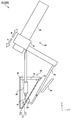
- FIG. 1 shows a side view (partially sectional view) of a dip coating apparatus according to Embodiment 1 of the present invention.
- FIG. 2 shows a side view (partially sectional view) of the dip coating apparatus according to Embodiment 1 of the present invention.
- FIG. 3 shows a side view (partially sectional view) of the dip coating apparatus according to Embodiment 2 of the present invention.
- FIG. 4 shows a side view (partially sectional view) of the dip coating apparatus according to Embodiment 2 of the present invention.
- FIG. 5 shows a side view (partially sectional view) of a dip coating apparatus according to Embodiment 3 of the present invention.
- FIG. 1 shows a side view (partially sectional view) of a dip coating apparatus according to Embodiment 1 of the present invention.
- FIG. 2 shows a side view (partially sectional view) of the dip coating apparatus according to Embodiment 1 of the present invention.
- FIG. 3 shows a
- FIG. 6 shows a side view (partially sectional view) of a dip coating apparatus according to Embodiment 3 of the present invention.
- FIG. 7 shows a side view (partially sectional view) of a dip coating apparatus according to Embodiment 3 of the present invention.
- FIG. 8 shows a side view (partially sectional view) of a dip coating apparatus according to Embodiment 4 of the present invention.
- FIG. 9 is a perspective view (partially sectional view) of the dip coating apparatus according to Embodiment 5 of the present invention.
- FIG. 10 shows a side view (partially sectional view) of a dip coating apparatus according to Embodiment 6 of the present invention.
- FIG. 11 is a cross-sectional view illustrating an example in which the first fixing portion is inserted into the lumen of the tubular body that is the member to be coated.
- the dip coating apparatus has a vertical direction and a horizontal direction.
- the Z direction in the drawing of the present application corresponds to the vertical direction of the dip coating apparatus, and the XY direction in the drawing of the present application corresponds to a direction parallel to the liquid surface of the coating material.
- the dip coating apparatus of the present invention coats an application material on a member to be applied, and stores a storage tank that stores the application material, a first fixing portion that holds the application member, and a wall of the storage tank And a second fixing portion that is provided directly or indirectly to the portion and acts as a magnetic attraction with the first fixing portion.
- the dip coating apparatus of the present invention has a magnetic attractive force acting between a first fixing portion that holds a member to be coated and a second fixing portion that is provided on the wall of the storage tank, thereby The application member is fixed in a state of being drawn to the second fixing portion.
- the first fixing portion maintains the state of being fixed to the second fixing portion while holding the member to be coated. Difficult to move in the storage tank. Further, in the dip coating apparatus of the present invention, it is possible to suppress the application material from adhering to a support member that engages with, for example, a comb-shaped fixing member for each dipping operation of a member to be coated as in the conventional dip coating apparatus, The use efficiency of the coating material is increased.
- FIG. 1 is a side view (partially sectional view) when the member to be coated is immersed in a coating material
- FIG. 2 is a side view (partial sectional view) when the member to be coated is pulled up.
- the dip coating apparatus 10 ⁇ / b> A includes a storage tank 30, a first fixing unit 40, and a second fixing unit 50.
- the member to be coated 20 is a member to which the coating material 70 is coated at least on the outer surface, and examples thereof include a resin-made, glass- or metal-made container or tubular body.
- the container is a member that stores various gases, liquids, and solids.
- the tubular body is a tubular member having a lumen, and can be, for example, a single tube structure, a multiple tube structure formed of a plurality of concentric tubes having different diameters, or a combination thereof.
- the dip coating apparatus 10 of the present invention can fix the position of the member to be coated 20 in the storage tank 30 by the magnetic attraction generated between the first fixing part 40 and the second fixing part 50. Therefore, the present invention is suitable for coating the member to be coated 20 that is susceptible to buoyancy in the coating material 70. Furthermore, since the dip coating apparatus 10 of the present invention can increase the uniformity of the coating film thickness, it is particularly suitable for coating precision instruments and products in the medical field that require stable product quality.
- the coated member 20 is preferably a medical tubular body.
- the medical tubular body is a tube made of resin, metal, etc., or a combination thereof, and is used for, for example, a catheter, a resin stent, a drainage tube, and the like.
- Many medical tubular bodies are made of resin, and many have a small specific gravity with respect to the coating material 70 because of having a lumen. For this reason, the medical tubular body floats in response to buoyancy in the coating material 70, contacts the side wall of the storage tank 30 that stores the coating material 70, or swings in the coating material 70. Its position is difficult to determine. However, as will be described later, the dip coating apparatus 10 of the present invention can easily fix the position in the storage tank 30 even if the coated member 20 is susceptible to buoyancy.
- the medical tubular body is a medical catheter. If the dip coating apparatus 10 of the present invention is used, the coated member 20 can be easily coated, so that the productivity of the medical catheter can be increased.
- the medical catheter may be a balloon catheter. This is because the dip coating apparatus 10 of the present invention is also suitable for the member to be coated 20 that is susceptible to buoyancy.
- the coating material 70 applied to the member to be coated 20 may be liquid or liquid.
- silicone resin, urethane resin, acrylic resin, fluororesin, or a mixture thereof is diluted with a solvent. Things can be used.
- the type of the coating material 70 takes into consideration the functions required of the member to be coated 20, for example, improved slidability of the member to be coated, good washability of the storage tank, ease of handling, protection and reinforcement of the member to be coated. And can be selected as appropriate.
- the type of the coating material 70 is appropriately selected in consideration of the harmlessness to the human body, antithrombotic properties, especially when a drug is applied, and its therapeutic effect. be able to.
- the storage tank 30 stores the coating material 70 and has a wall portion 31.
- the wall portion 31 includes a bottom wall 32 and a side wall 33.
- the shape of the storage tank 30 is not particularly limited as long as it has an opening 34 for taking the member to be applied 20 and the first fixing portion 40 into and out of the storage tank 30.
- a lid (not shown) may be provided at the opening 34 of the storage tank 30 in order to prevent foreign matter from entering the coating material 70.
- the opening 34 is preferably provided above the side wall 33 of the storage tank 30, and is provided at the upper end of the side wall 33. It is more preferable.
- the side wall 33 of the storage tank 30 is inclined with respect to a direction (Z direction) perpendicular to the liquid surface (XY direction) of the coating material 70. . 1 and 2, the inclination angle is represented by ⁇ . If the side wall 33 of the storage tank 30 is inclined, the area of the opening portion of the storage tank 30 for immersing the coated member 20 in the coating material 70 or pulling up the coated member 20 from the coating material 70 is increased. Can take. As a result, in the dip coating apparatus of the present invention, the separation distance between the member to be coated 20 and the side wall 33 can be increased, so that the member to be coated 20 is unlikely to contact the side wall 33. Thereby, generation
- the coated member 20 may come into contact with the side wall 33, so the lower limit value of the inclination angle ⁇ is preferably 5 degrees, more preferably 10 degrees, and even more preferably 15 degrees.
- the upper limit value of the inclination angle ⁇ is preferably 70 degrees. 60 degrees is more preferable, and 50 degrees is more preferable.
- the storage tank 30 is cut off on the upper side (opening 34 side) in the vertical direction (Z direction) with respect to the liquid surface (XY direction) of the coating material 70.
- the area is preferably larger than the cross-sectional area on the lower side (bottom wall 32 side).
- the coating material 70 in the storage tank 30 has a first cross section that is parallel to the liquid surface (XY direction) of the coating material 70 and close to the liquid surface, and has a second cross section closer to the bottom wall than the first cross section. It is preferable that it is larger than the area. That is, the inner diameter of the upper cross section of the storage tank 30 is preferably larger than the inner diameter of the lower cross section.
- the area of the opening part of the storage tank for immersing a to-be-coated member in a coating material, or pulling up a to-be-coated member out of a coating material can be taken.
- the separation distance between the member to be coated and the side wall can be increased, so that the member to be coated does not easily come into contact with the side wall.
- the material of the storage tank 30 is not particularly limited.
- metal materials such as stainless steel such as SUS304, SUS316, SUS420, and SUS430, and polymer materials such as polypropylene (PP), polyethylene (PE), and polytetrafluoroethylene (PTFE).
- PP polypropylene
- PE polyethylene
- PTFE polytetrafluoroethylene
- a permanent magnet or electromagnet having a high magnetic flux density such as a neodymium magnet or a samarium cobalt magnet, or a combination thereof can be used.
- the storage tank 30 is made of a material having low frictional resistance and good slipperiness. Preferably it is.
- a stainless steel such as SUS304 coated with a fluororesin such as PTFE can be used as the storage tank 30.
- a magnetic material it is preferable not to use a magnetic material as the material of the storage tank 30 in order to shield the magnetic field between the first fixing part 40 and the second fixing part 50 as much as possible and to secure the strength of the magnetic attraction.
- the storage tank 30 is preferably thinner.
- a thick portion 35 is provided on the side wall 33 of the storage tank 30. Since the strength of the magnetic attractive force acting between the first fixing part 40 and the second fixing part 50 in the thick part 35 of the storage tank 30 can be weakened, the coated member 20 and the first fixing part from the storage tank 30 It becomes easy to take out 40.
- the thick portion 35 is preferably formed so as to increase in thickness from the lower side to the upper side of the storage tank 30 in the direction perpendicular to the liquid level of the coating material.
- the bottom wall side of the thick portion 35 is formed so as to become thicker from the lower side to the upper side of the storage tank 30.
- fixed part 50 does not increase rapidly, the 1st fixing
- the dip coating apparatus of the present invention the impact and vibration applied to the first fixing part 40 when the second fixing part 50 passes through the thick part 35 can be suppressed, and therefore, the dip coating apparatus is applied to the member 20 to be applied.
- the thickness of the coating material 70 can be made uniform.
- maintains the to-be-coated member 20 in the storage tank 30, and a magnetic attraction works between the 2nd fixing
- the shape of the first fixing portion 40 can be appropriately set as follows according to the specific gravity of the member to be coated 20 with respect to the coating material 70, the shape of the member to be coated 20, and the like.
- the first fixing part 40 may be a fixing member. That is, the 1st fixing
- the first fixing portion 40 may include a gripping portion that grips a portion other than the application range of the application target member 20 and may be fixed by holding the application target member 20.
- the member to be coated 20 when the specific gravity of the member to be coated 20 with respect to the coating material 70 is small, the member to be coated 20 may move due to buoyancy in the coating material 70. Therefore, when the specific gravity of the member to be coated 20 with respect to the coating material 70 is small, the entire member to be coated 20 is preferably fixed.
- the member to be coated 20 is a tubular body, the lumen of the tubular body It is preferable that the 1st fixing
- the first fixing portion 40 is preferably a rod-shaped body (bar shape).
- the rod-shaped body is a rod-shaped member inserted into the lumen of the tubular body, and prevents the tubular body from being bent by receiving buoyancy in the coating material 70.
- the coating material 70 adheres to the outer surface of the member to be coated 20, but the liquid surface of the coating material 70 (XY direction) is covered.
- the axial direction of the application member 20 is arranged vertically, the thickness of the application film becomes uniform.
- the member to be coated 20 is a tubular body having elasticity
- the member to be coated 20 is pulled out of the coating material 70 while keeping the tubular body as straight as possible and maintaining a state perpendicular to the liquid surface.
- a rod-like body is preferable as a member for holding the tubular body. Further, if the rod-like body is inserted into the lumen of the tubular body, the coating material 70 that enters the lumen of the tubular body can be reduced, and therefore, the adhesion of the coating material 70 to the inner surface of the tubular body is suppressed. it can.
- the rod-shaped body is not particularly limited as long as it is a shape that can be inserted into the lumen of the tubular body, but is preferably a columnar shape or a polygonal column shape in order to facilitate manufacture. Moreover, in order to suppress stress concentration when the rod-shaped body and the tubular body are in contact with each other, the rod-shaped body is preferably a columnar shape or an elliptical columnar shape. Furthermore, in order to facilitate the insertion of the rod-like body into the tubular body, it is preferable that the major axis direction of the rod-like body is parallel to the major axis direction of the tubular body.
- the rod-shaped body may have a flow path penetrating along the axial direction. That is, the rod-shaped body may have a cylindrical shape or a shape in which grooves are formed on the surface of a columnar object such as a columnar shape or a polygonal columnar shape.
- a columnar object such as a columnar shape or a polygonal columnar shape.
- the rod-shaped body is inserted into the tubular body from the inner surface of the tubular body.
- the upper limit value of the distance to the outer surface of the first fixed portion 40 is preferably 150 ⁇ m, preferably 140 ⁇ m, and preferably 130 ⁇ m.
- the distance between the inner surface of the tubular body and the outer surface of the first fixing portion 40 in a state where the rod-like body is inserted into the tubular body is preferably 150 ⁇ m, preferably 140 ⁇ m, and preferably 130 ⁇ m.
- fixed part 50 is provided in the wall part 31 of the storage tank 30, and a magnetic attraction works between the 1st fixing
- FIG. Thereby, even if the member to be coated 20 receives buoyancy in the coating material 70, the member to be coated 20 is fixed in the state of being drawn to the second fixing part 50 in the storage tank 30. Therefore, even if the member to be coated 20 receives buoyancy in the coating material 70 in the storage tank 30, the first fixing portion 40 maintains the state of being fixed to the second fixing portion 50 while holding the member to be coated 20. Therefore, the member to be coated 20 is difficult to move in the storage tank 30.
- the second fixing part 50 may be a fixing member. That is, the second fixing portion 50 may be provided on the second fixing member.
- fixed part 50 may be provided in the inner side of the wall part 31 of the storage tank 30, and may be provided in the outer side, the point which enlarges the capacity
- fixed part 40 has a magnet and the wall part 31 is a material attracted
- the wall of the storage tank and the second fixing part are integrated means that the storage tank is formed of a material that acts as a magnetic attraction between the storage tank and the first fixing part.
- At least one of the first fixing part 40 and the second fixing part 50 has a magnet. If at least one of the first fixing part 40 and the second fixing part 50 has a magnet, a magnetic attractive force can be generated between the first fixing part 40 and the second fixing part 50. Since the magnet needs to have a sufficient magnetic force even through the side wall 33 of the storage tank 30, a permanent magnet having a high magnetic flux density such as a neodymium magnet or a samarium cobalt magnet can be used.
- One of the first fixing portion 40 and the second fixing portion 50 may be a magnet, and the other may be a magnetic material that attracts the magnet.
- metal materials such as stainless steel, such as SUS304, SUS316, SUS420, SUS430, etc. which attract a magnet can be used for the 2nd fixing
- metal materials, such as stainless steel, such as SUS304, SUS316, SUS420, SUS430, etc. which attract a magnet can be used for the 1st fixing
- the magnet is an electromagnet. This is because when the magnet is an electromagnet, the strength of the magnetic attractive force can be adjusted.
- the dip coating apparatus 10 includes a first driving unit 61 connected to the first fixing unit 40, a first shaft unit 62 that supports the first driving unit 61, a second fixing unit 50, and a first driving unit.
- a driving means 60 having a connecting portion 63 for connecting 61 and a guide portion 64 for guiding the path of the second fixing portion 50 may be provided.
- the upper part of the first fixing unit 40 is connected to the first driving unit 61.
- the axial direction of the first shaft portion 62 that supports the first drive portion 61 is arranged in parallel with the inclined portion of the side wall 33 of the storage tank 30. For this reason, by moving the 1st drive part 61 along the 1st axial part 62, the 1st fixing
- the first driving unit 61 that moves the first fixing unit 40 is preferably connected to the second fixing unit 50. Since the 1st fixing part 40 and the 2nd fixing part 50 which magnetic attraction act can be interlocked, the position of the member 20 to be applied is easily fixed in the entire Z direction of the storage tank 30. In FIG. 1 and FIG. 2, the first drive unit 61 and the second fixing unit 50 are connected via the connection unit 63.
- the dip coating apparatus 10A may be provided with a guide part 64 that guides the path of the second fixing part 50. it can. In order to suppress the weakening of the magnetic attractive force, it is preferable that at least a part of the guide portion 64 is inclined, and it is more preferable that the guide portion 64 is inclined in parallel with the side wall 33 of the storage tank 30.
- FIGS. 3 to 10 are side views (partial sectional views) of the dip coating apparatus, and FIG. 9 is a perspective view (partial sectional view) of the dip coating apparatus.
- FIG. 3 shows a side view (partially sectional view) when the member 20 to be coated is immersed in the coating material 70
- FIG. 4 shows a side view when the member 20 to be coated is pulled up. (Partial sectional view).
- the outer diameter of the first fixing portion 40 of the dip coating apparatus 10B may not be uniform in the axial direction.
- the first fixing portion 40 of the dip coating apparatus 10B is a rod-shaped body (bar shape), and the outer diameter at one end of the rod-shaped body is preferably larger than the outer diameter at the other end. More preferably, the outer diameter is larger than the outer diameter on the opening 34 side.
- the first fixing portion 40 of the dip coating apparatus 10 ⁇ / b> B has a portion that protrudes toward the side wall 33 (hereinafter referred to as “convex portion”).
- convex portion a portion that protrudes toward the side wall 33
- the convex part 41 will contact the side wall 33 of the storage tank 30 previously.
- the separation distance between the member to be coated 20 and the side wall 33 can be secured to a certain extent, the member to be coated 20 is less likely to come into contact with the side wall 33, and application failure due to contact between the member to be coated 20 and the side wall 33 is prevented. Occurrence can be suppressed.
- the convex portion 41 is preferably provided at one end portion of the first fixing portion 40, and is provided at one end portion of the first fixing portion 40 disposed close to the bottom wall 32 side. More preferred.
- the convex portion 41 of the first fixing portion 40 is formed in a spherical shape having a diameter larger than the outer diameter of the member 20 to be coated, which is a tubular body.
- the spherical convex portion 41 can be formed by melting one end portion of the first fixed portion 40 with a laser or the like.
- the convex portion 41 may be formed by bending one end portion of the first fixing portion 40 in one direction using a press or the like. Further, the convex portion 41 formed into a desired shape by a laser or the like may be connected to the first fixing portion 40.
- the apparatus 10B since the side wall 33 of the storage tank 30 is not inclined, the first drive unit 61 moves in the same direction (Z direction) as the first fixed unit 40 and the second fixed unit 50. Therefore, the apparatus can be reduced in size in the XY direction compared with the first embodiment.
- FIGS. 5 shows a side view (partially sectional view) when the member 20 to be coated is immersed in the coating material 70
- FIG. 6 shows a side view (partially) when the member 20 to be coated is pulled up
- 7 is a side view when the first fixing portion 40 is pulled up (partially sectional view).
- the side wall 33 of the storage tank 30 of the dip coating apparatus 10C preferably has a portion protruding to the inside of the storage tank 30 (hereinafter referred to as “protrusion”).
- protrusion a portion protruding to the inside of the storage tank 30
- the protrusion part 36 becomes easy to contact the storage tank 30 previously.
- the separation distance between the member to be coated 20 and the side wall 33 can be secured to a certain extent, the member to be coated 20 becomes difficult to come into contact with the side wall 33 and poor coating due to contact between the member to be coated 20 and the side wall 33. Can be suppressed.
- the protrusion 36 is preferably formed on the lower side when the storage tank 30 is divided into three equal parts in the vertical direction (Z direction).
- the first fixing part 40 comes into contact with the protrusion 36 before reaching the desired application range when the member 20 to be applied is moved into the storage tank 30. This is because there is a fear.
- the protrusion part 36 should just be provided in a part of circumferential direction of the storage tank 30, in order to reduce the contact risk of the storage tank 30 and the to-be-coated member 20, the protrusion part 36 of the storage tank 30 is sufficient. More preferably, it is provided over the entire circumferential direction.
- the rectangular second fixing portion 50 is provided outside the protruding portion 36 of the storage tank 30, the protruding portion 36 is more likely to come into contact with the first fixing portion 40.
- 5 to 7 show an example in which the second fixing portion 50 is arranged outside the storage tank 30, but the magnetic attractive force acting between the first fixing portion 40 and the second fixing portion 50 is small.
- the second fixing portion 50 can also be disposed inside the storage tank 30 so that it can be completed.
- the second fixing part 50 is fixed to the wall part 31 of the storage tank 30, it is not necessary to provide a driving means for moving the second fixing part 50. Further, as in the second embodiment, since the side wall 33 of the storage tank 30 is not inclined, the apparatus can be reduced in size in the XY direction compared to the first embodiment.
- the dip coating apparatus 10 ⁇ / b> C is provided with driving means 60 for moving the member to be coated 20 and the first fixing part 40 into and out of the storage tank 30.
- the driving unit 60 includes a first driving unit 61 connected to the member to be coated 20, a first shaft unit 62 that supports the first driving unit 61, and a second driving unit connected to the first fixing unit 40. 65 and a second shaft portion 66 that supports the second drive portion 65.
- FIG. 8 shows a side view (partially sectional view) of a dip coating apparatus according to Embodiment 4 of the present invention.
- the dip coating apparatus 10 (10D) illustrated in FIG. 8 is a configuration example in which a magnetic attraction is applied between the first fixing unit 40 and the storage tank 30. That is, this is a configuration example in the case where the storage tank and the second fixing portion are integrated.
- the dip coating apparatus 10 ⁇ / b> D coats the member to be coated 20 with the coating material 70, holds the storage tank 30 for storing the coating material 70, the member to be coated 20, and It has the 1st fixing
- the dip coating apparatus 10 ⁇ / b> D can simplify the structure of the apparatus because a magnetic attractive force acts between the first fixed portion 40 and the storage tank 30.
- fixed part 40 and the storage tank 30 should just have a magnet, and an electromagnet may be sufficient as a magnet.
- a metal material such as stainless steel such as SUS304, SUS316, SUS420, or SUS430 that attracts the magnet can be used for the other.
- FIG. 9 is a perspective view (partially sectional view) of the dip coating apparatus according to Embodiment 5 of the present invention.
- the dip coating apparatus 10 (10E) shown in FIG. 9 is a structural example in the case of applying a plurality of members to be applied 20 together.
- the coating material 70 can be applied to the plurality of members to be coated 20 in parallel, so that productivity is improved.
- FIG. 10 shows a side view (partially sectional view) of the dip coating apparatus according to the sixth embodiment of the present invention, and a configuration example in which a magnetic repulsive force is exerted between the first fixing portion 40 and the buffer member 55.
- the dip coating apparatus 10 (10F) it is preferable that the 1st fixing
- the dip coating apparatus 10 ⁇ / b> F has a buffer member 55 that acts on the side wall 33 of the storage tank 30 so that a magnetic repulsive force acts with the first fixing portion 40.
- the buffer member 55 is disposed above the bottom wall 32 of the storage tank 30.
- the buffer member 55 is provided inside the side wall 33, but the buffer member 55 may be provided outside the side wall 33 (not shown). In this manner, the buffer member 55 can be suitably used when the storage tank 30 in which the side wall 33 is not inclined is used as in the above-described second to fourth embodiments.
- the present invention is preferably a medical tubular body manufactured by the dip coating apparatus.
- the medical tubular body manufactured by the dip coating apparatus can be expected to have high slidability and a protective effect of the tubular body by the coating film because the coating material 70 is uniformly coated.
- the present invention relates to a method for manufacturing a coated member obtained by dip-coating a coating material on a member to be coated, and (1) a step of fixing the member to be coated to a first fixing portion. And (2) a step of immersing the member to be coated in a storage tank in which the coating material is stored, and (3) a first fixing portion provided directly or indirectly on the wall of the storage tank. A step of bringing the second fixed portion close to the second fixed portion capable of generating magnetic attraction between the fixed portion, a step of (4) releasing the proximity of the first fixed portion and the second fixed portion, and (5) a member to be coated. And a step of pulling up from the storage tank in which the coating material is stored.
- FIG. 11 is a cross-sectional view showing an example in which the first fixing portion 40 of a rod-shaped body having a circular cross section perpendicular to the axial direction (Z direction) is inserted into the lumen of the member to be coated 20.
- fixed part The to-be-coated member 20 is fixed to the 1st fixing
- the member 20 to be coated is fixed to the first fixing portion 40 in a state in which the magnetic attractive force acting between the first fixing portion 40 and the second fixing portion 50 is sufficiently weak, that is, the first fixing portion 40 and the second fixing portion. 50 in a state of being separated.
- the member 20 to be applied is a medical tubular body having a multi-cylinder structure, and is a balloon catheter 21 having a balloon portion 22 formed in a part of the multi-cylinder structure.
- the first fixing portion 40 is inserted into the lumen of the balloon catheter 21, and a part of the first fixing portion 40 on the storage tank 30 side is exposed from the balloon catheter 21.
- the member to be coated 20 is a tubular body, and the first fixing portion 40 is inserted into the lumen of the tubular body in this step of fixing the member to be coated 20 to the first fixing portion 40.
- Step of immersing the member to be coated in the storage tank in which the coating material is stored the member to be coated 20 is immersed in the storage tank 30 in which the coating material 70 is stored. Specifically, in FIG. 1, by moving the first drive unit 61 along the first shaft portion 62 in the direction A in FIG. 1, the first fixed unit 40 and the member to be coated 20 are also side walls of the storage tank 30. In order to move in the A direction along 33, the member 20 to be coated is immersed in the coating material 70 of the storage tank 30.
- the second fixing portion 50 is provided directly or indirectly on the wall portion 31 of the storage tank 30 and can generate a magnetic attractive force with the first fixing portion 40.
- the member to be coated 20 fixed to the first fixing part 40 is attracted to the second fixing part 50 and fixed in the storage tank 30.
- the step of fixing the member to be coated to the first fixing portion (2) the step of immersing the member to be coated in the storage tank in which the coating material is stored, and (3) the first fixing portion. Is close to the second fixed part that is directly or indirectly provided on the wall of the storage tank and can generate magnetic attraction with the first fixed part, after the process is completed. These steps may be performed, or may be performed simultaneously or at a time difference.
- the method for manufacturing a coated member according to the present invention includes the step of bringing the first fixing portion 40 closer to the second fixing portion 50 capable of generating magnetic attraction between the first fixing portion 40 and the first fixing portion 40, the first fixing portion 40 Since the portion 40 attracts the second fixed portion 50 in a state in which the member to be coated 20 is fixed, the member to be coated 20 is difficult to move in the storage tank 30. Therefore, the method for manufacturing a coated member of the present invention can fix the position of the member to be coated 20 in the storage tank 30, and is therefore suitable for use when the member to be coated 20 is susceptible to buoyancy. Yes.
- the coating material can be prevented from adhering to the support member that engages with the comb-shaped fixing member, for example, in each dipping operation of the coated member as in the conventional dip coating method, the usage efficiency of the coating material is increased. It is done.
- At least one of the first fixing portion 40 and the second fixing portion 50 has an electromagnet, and the first fixing portion is provided directly or indirectly on the wall portion of the storage tank, and between the first fixing portion and the first fixing portion. Then, it is preferable to generate a magnetic attractive force by an electromagnet between the first fixed portion 40 and the second fixed portion 50 after the step of approaching the second fixed portion capable of generating a magnetic attractive force. If at least one of the first fixing part 40 and the second fixing part 50 has an electromagnet, the strength of the magnetic attractive force can be adjusted.
- the distance between the first fixing portion 40 and the second fixing portion 50 is rapidly reduced while the first fixing portion is It can suppress that 40 and the 2nd fixing
- the impact and vibration given to the coating material 70 can be suppressed to a small extent, and therefore the thickness of the coating material 70 applied to the member to be coated 20 can be made uniform.
- the coating material 70 stores the member to be coated 20 by moving the first fixing portion 40 in the B direction.
- the first fixing part 40 and the second fixing part 50 are separated from each other until the magnetic attraction is weakened.
- FIG. 2 when the thick portion 35 is provided in the storage tank 30, the first thick portion 35 of the storage tank 30 in which the magnetic attraction of the first fixing portion 40 and the second fixing portion 50 is weakened. What is necessary is just to space apart the fixing
- the step of releasing the proximity of the first fixing portion and the second fixing portion, and (5) the step of pulling up the member to be coated from the storage tank in which the coating material is stored are either The other process may be performed after one process is completed, or may be performed simultaneously or with a time difference.
- a member in which the member to be coated 20 is coated with the coating material 70 can be obtained.
- the method for producing a coated member of the present invention suppresses adhesion of a coating material to a support member that engages with, for example, a comb-shaped fixing member every time a member to be coated is immersed, as in the conventional dip coating method. Therefore, the usage efficiency of the coating material is increased.
Landscapes
- Coating Apparatus (AREA)
- Application Of Or Painting With Fluid Materials (AREA)
Abstract
Description
本発明のディップコーティング装置は、被塗布部材に塗布材料をコーティングするものであって、塗布材料を貯留する貯留槽と、被塗布部材を保持する第1固定部と、貯留槽の壁部に直接または間接に設けられており、第1固定部との間で磁気引力が働く第2固定部とを有する。本発明のディップコーティング装置は、被塗布部材を保持する第1固定部と、貯留槽の壁部に設けられている第2固定部との間で磁気引力が働くことにより、貯留槽内で被塗布部材は、第2固定部に引き寄せられた状態で固定される。したがって、被塗布部材が貯留槽内の塗布材料中で浮力を受けても、第1固定部は被塗布部材を保持したまま第2固定部に固定された状態を維持するため、被塗布部材は貯留槽内で移動しにくい。また、本発明のディップコーティング装置では、従来のディップコーティング装置のように被塗布部材の浸漬操作毎に例えば櫛状の固定部材と係合する支持部材に塗布材料が付着することを抑制できるため、塗布材料の使用効率が高められる。
図1および図2を用いて、本発明の実施の形態1に係るディップコーティング装置10(10A)について説明する。図1は、被塗布部材を塗布材料に浸けたときの側面図(一部断面図)であり、図2は、被塗布部材が引き上げられているときの側面図(一部断面図)を表す。ディップコーティング装置10Aは、貯留槽30と、第1固定部40と、第2固定部50とを有する。
まず、ディップコーティング装置10によって塗布材料70が塗布される被塗布部材20について説明する。被塗布部材20は、少なくとも外表面に塗布材料70が塗布される部材であり、例えば、樹脂製、ガラス製や金属製の容器や管状体などが挙げられる。容器は、各種の気体、液体、固体を収納する部材である。管状体は、内腔を有する筒状の部材であり、例えば、単筒構造、直径の異なる複数の同心状の管から形成される多重筒構造、或いはこれらの組み合わせとすることができる。
被塗布部材20に塗布される塗布材料70は液体または液状のものであればよく、例えばシリコーン樹脂、ウレタン樹脂、アクリル樹脂、フッ素樹脂、或いはこれらの混合物等を溶媒によって希釈したものを用いることができる。塗布材料70の種類は、被塗布部材20に求められる機能、例えば、被塗布部材の摺動性向上、貯留槽の洗浄性がよいこと、取り扱いの容易性、被塗布部材の保護および補強を考慮して適宜選択することができる。また、被塗布部材が医療用の場合には、塗布材料70の種類は、人体に無害であること、抗血栓性、中でも薬剤を塗布する場合にはその治療効果等を考慮して適宜選択することができる。
貯留槽30は、塗布材料70を貯留するものであり、壁部31を有する。壁部31は底壁32と側壁33から構成される。貯留槽30の形状は特に制限されず、被塗布部材20および第1固定部40を貯留槽30内に出し入れするための開口部34を有していればよい。また、貯留槽30の開口部34には、塗布材料70への異物の混入を抑止するために蓋(図示していない)が設けられてもよい。塗布材料70の液面(X-Y方向)に対する垂直方向(Z方向)において、開口部34は、貯留槽30の側壁33の上側に設けられることが好ましく、側壁33の上側端部に設けられることがより好ましい。
第1固定部40は、貯留槽30内において被塗布部材20を保持するものであり、後述する第2固定部50との間で磁気引力が働く。第1固定部40の形状は、塗布材料70に対する被塗布部材20の比重や被塗布部材20の形状などに応じて以下のように適宜設定することができる。第1固定部40は、固定部材であってもよい。すなわち、第1固定部40は、第1固定部材に設けられていてもよい。
第2固定部50は、貯留槽30の壁部31に設けられており、第1固定部40との間で磁気引力が働くものである。これにより、被塗布部材20が塗布材料70中で浮力を受けても、貯留槽30内で被塗布部材20は、第2固定部50に引き寄せられた状態で固定される。したがって、被塗布部材20が貯留槽30内の塗布材料70中で浮力を受けても、第1固定部40は被塗布部材20を保持したまま第2固定部50に固定された状態を維持するため、被塗布部材20は貯留槽30内で移動しにくい。また、従来のディップコーティング装置のように被塗布部材の浸漬操作毎に、例えば櫛状の固定部材と係合する支持部材に塗布材料が付着することを抑制できるため、塗布材料の使用効率が高められる。第2固定部50は、固定部材であってもよい。すなわち、第2固定部50は、第2固定部材に設けられていてもよい。
図3および図4を用いて、貯留槽30の側壁33に傾斜が設けられない実施の形態2に係るディップコーティング装置10(10B)について説明する。図3は、被塗布部材20が塗布材料70中に浸けられているときの側面図(一部断面図)を表し、図4は、被塗布部材20が引き上げられているときの側面図(一部断面図)を表す。
図5~図7を用いて、貯留槽30の側壁33に傾斜が設けられない実施の形態3に係るディップコーティング装置10(10C)について説明する。図5は、被塗布部材20が塗布材料70に浸けられているときの側面図(一部断面図)を表し、図6は、被塗布部材20が引き上げられているときの側面図(一部断面図)を表し、図7は、第1固定部40が引き上げられているときの側面図(一部断面図)を表す。
図8は、本発明の実施の形態4に係るディップコーティング装置の側面図(一部断面図)を表す。図8に示すディップコーティング装置10(10D)は、第1固定部40と貯留槽30との間で磁気引力を働かせる構成例である。つまり、貯留槽と第2固定部とが一体の場合の構成例である。図8に示されるように、ディップコーティング装置10Dは、被塗布部材20に塗布材料70をコーティングするものであって、塗布材料70を貯留する貯留槽30と、被塗布部材20を保持し、かつ貯留槽30との間で磁気引力が働く第1固定部40とを有する。ディップコーティング装置10Dは、第1固定部40と貯留槽30との間で磁気引力が働くため、装置の構造を簡素化することができる。なお、第1固定部40と貯留槽30の少なくともいずれか一方が磁石を有していればよく、磁石は電磁石でもよい。この場合、他方は磁石と引き合うSUS304、SUS316、SUS420、SUS430等のステンレス鋼等の金属材料を用いることができる。
図9は、本発明の実施の形態5に係るディップコーティング装置の斜視図(一部断面図)である。図9に示すディップコーティング装置10(10E)は、複数の被塗布部材20を一緒に塗布する場合の構成例である。図9に示されるように、並行している複数の第1固定部40(40A、40B、40C)が、並行している複数の被塗布部材20(20A、20B、20C)をそれぞれ保持することが好ましい。このように第1固定部40を構成することにより、並行している複数の被塗布部材20に対しても塗布材料70を塗布することができるため、生産性が高められる。
図10は、本発明の実施の形態6に係るディップコーティング装置の側面図(一部断面図)を表しており、第1固定部40と緩衝部材55との間で磁気斥力を働かせる構成例を示している。ディップコーティング装置10(10F)では、第1固定部40が磁石を備え、貯留槽30が磁石と引き合うステンレス鋼で構成されていることが好ましい。図10に示すように、ディップコーティング装置10Fは、貯留槽30の側壁33に、第1固定部40との間で磁気斥力が働く緩衝部材55を有していることが好ましい。これにより、緩衝部材55が設けられている領域において、第1固定部40が貯留槽30に接触するリスクを低減できる。緩衝部材55は、貯留槽30の底壁32よりも上側に配置されていることがより好ましい。図10では、緩衝部材55は側壁33の内側に設けられているが、緩衝部材55は側壁33の外側に設けられていてもよい(図示せず)。このように緩衝部材55を設ける態様は、上述した実施の形態2~4のように、側壁33が傾斜していない貯留槽30を用いる場合に好適に使用できる。
本発明は、被塗布部材に塗布材料をディップコーティングして得られるコーティングされた部材の製造方法であって、(1)被塗布部材を第1固定部に固定する工程と、(2)被塗布部材を、塗布材料が貯留されている貯留槽内に浸ける工程と、(3)第1固定部を、貯留槽の壁部に直接または間接に設けられており第1固定部との間で磁気引力を発生可能な第2固定部に近づける工程と、(4)第1固定部と第2固定部との近接を解除する工程と、(5)被塗布部材を、塗布材料が貯留されている貯留槽内から引き上げる工程と、を含む。実施の形態1にかかるディップコーティング装置の構成を示す図1、図2、図11を用いて、本発明のコーティングされた部材の製造方法について説明する。図11は、被塗布部材20の内腔に、軸方向(Z方向)に垂直な断面が円形の棒状体の第1固定部40を挿入した例を示す断面図を表す。
被塗布部材20を第1固定部40に固定する。被塗布部材20の第1固定部40への固定は、第1固定部40と第2固定部50との間に働く磁気引力が十分弱い状態で、すなわち第1固定部40と第2固定部50を離間させた状態で行う。
図1に示すように、被塗布部材20を、塗布材料70が貯留されている貯留槽30内に浸ける。具体的には、図1において、第1駆動部61を第1軸部62に沿って図1のA方向に移動させることにより、第1固定部40および被塗布部材20も貯留槽30の側壁33に沿ってA方向に移動するため、貯留槽30の塗布材料70中に被塗布部材20が浸けられる。
第1固定部40を、貯留槽30の壁部31に直接または間接に設けられており第1固定部40との間で磁気引力を発生可能な第2固定部50に近づける。第1固定部40に固定された被塗布部材20は第2固定部50に引き寄せられて、貯留槽30内で固定される。
被塗布部材20が所望の塗布範囲まで浸かったら、第1固定部40と第2固定部50との近接を解除する。したがって、第1固定部40と第2固定部50の固定状態が解除される。
図2に示すように、第1固定部40をB方向に移動させて被塗布部材20を塗布材料70が貯留されている貯留槽30内から引き上げ、磁気引力が弱まるまで第1固定部40と第2固定部50を離間させる。図2に示すように貯留槽30に肉厚部35が設けられている場合には、第1固定部40と第2固定部50の磁気引力が弱まる貯留槽30の肉厚部35で第1固定部40と第2固定部50を離間させればよい。
20:被塗布部材
21:バルーンカテーテル
22:バルーン部
30:貯留槽
31:壁部
32:底壁、33:側壁、34:開口部、35:肉厚部、36:突出部
40:第1固定部
41:凸部
50:第2固定部
55:緩衝部材
60:駆動手段
61:第1駆動部
62:第1軸部
63:接続部
64:案内部
65:第2駆動部
66:第2軸部
70:塗布材料
Claims (20)
- 被塗布部材に塗布材料をコーティングするディップコーティング装置であって、
前記塗布材料を貯留する貯留槽と、
前記被塗布部材を保持する第1固定部と、
前記貯留槽の壁部に直接または間接に設けられており、前記第1固定部との間で磁気引力が働く第2固定部とを有することを特徴とするディップコーティング装置。 - 前記第1固定部が第1固定部材に設けられており、
前記第2固定部が第2固定部材に設けられている請求項1に記載のディップコーティング装置。 - 前記貯留槽と前記第2固定部とが一体である請求項1に記載のディップコーティング装置。
- 前記貯留槽の側壁の少なくとも一部が、前記塗布材料の液面に対する垂直方向を基準に傾斜している請求項1~3のいずれか一項に記載のディップコーティング装置。
- 前記第1固定部が棒形状である請求項1~4のいずれか一項に記載のディップコーティング装置。
- 前記第1固定部は前記貯留槽の側壁に向かって凸となる部分を有する請求項1~5のいずれか一項に記載のディップコーティング装置。
- 前記貯留槽の側壁には肉厚部が設けられている請求項1~6のいずれか一項に記載のディップコーティング装置。
- 前記肉厚部は、前記塗布材料の液面に対する垂直方向において、前記貯留槽の下側から上側に向かって厚くなるように形成されている請求項7に記載のディップコーティング装置。
- 前記貯留槽の側壁は、前記貯留槽の内側に突出した部分を有する請求項1~8のいずれか一項に記載のディップコーティング装置。
- 前記第1固定部と前記第2固定部のうち少なくとも一方が磁石を有する請求項1~9のいずれか一項に記載のディップコーティング装置。
- 前記磁石が電磁石である請求項10に記載のディップコーティング装置。
- 前記貯留槽の側壁に、前記第1固定部との間で磁気斥力が働く緩衝部材を有している請求項1~11のいずれか一項に記載のディップコーティング装置。
- 並行している複数の前記第1固定部が、並行している複数の前記被塗布部材をそれぞれ保持する請求項1~12のいずれか一項に記載のディップコーティング装置。
- 前記被塗布部材が医療用管状体である請求項1~13のいずれか一項に記載のディップコーティング装置。
- 前記医療用管状体が医療用カテーテルである請求項14に記載のディップコーティング装置。
- 前記医療用カテーテルがバルーンカテーテルである請求項15に記載のディップコーティング装置。
- 請求項1~16のいずれか一項に記載のディップコーティング装置によって製造された医療用管状体。
- 被塗布部材に塗布材料をディップコーティングして得られるコーティングされた部材の製造方法であって、
前記被塗布部材を第1固定部に固定する工程と、
前記被塗布部材を、前記塗布材料が貯留されている貯留槽内に浸ける工程と、
前記第1固定部を、前記貯留槽の壁部に直接または間接に設けられており前記第1固定部との間で磁気引力を発生可能な第2固定部に近づける工程と、
前記第1固定部と前記第2固定部との近接を解除する工程と、
前記被塗布部材を、前記塗布材料が貯留されている貯留槽内から引き上げる工程と、を含むことを特徴とするコーティングされた部材の製造方法。 - 前記第1固定部と前記第2固定部のうち少なくとも一方が電磁石を有しており、
前記第1固定部を、前記貯留槽の壁部に直接または間接に設けられており前記第1固定部との間で磁気引力を発生可能な第2固定部に近づける工程の後に、前記第1固定部と前記第2固定部の間で前記電磁石による磁気引力を発生させる請求項18に記載のコーティングされた部材の製造方法。 - 前記被塗布部材が管状体であり、
前記被塗布部材を第1固定部に固定する工程において前記管状体の内腔に前記第1固定部を挿通する請求項18または19に記載のコーティングされた部材の製造方法。
Priority Applications (2)
| Application Number | Priority Date | Filing Date | Title |
|---|---|---|---|
| US15/570,253 US10625298B2 (en) | 2015-04-28 | 2016-02-26 | Dip coating device and method for producing coated member |
| JP2017515411A JP6594415B2 (ja) | 2015-04-28 | 2016-02-26 | ディップコーティング装置およびコーティングされた部材の製造方法 |
Applications Claiming Priority (2)
| Application Number | Priority Date | Filing Date | Title |
|---|---|---|---|
| JP2015092285 | 2015-04-28 | ||
| JP2015-092285 | 2015-04-28 |
Publications (1)
| Publication Number | Publication Date |
|---|---|
| WO2016174913A1 true WO2016174913A1 (ja) | 2016-11-03 |
Family
ID=57199725
Family Applications (1)
| Application Number | Title | Priority Date | Filing Date |
|---|---|---|---|
| PCT/JP2016/055935 Ceased WO2016174913A1 (ja) | 2015-04-28 | 2016-02-26 | ディップコーティング装置およびコーティングされた部材の製造方法 |
Country Status (3)
| Country | Link |
|---|---|
| US (1) | US10625298B2 (ja) |
| JP (1) | JP6594415B2 (ja) |
| WO (1) | WO2016174913A1 (ja) |
Cited By (1)
| Publication number | Priority date | Publication date | Assignee | Title |
|---|---|---|---|---|
| CN117960489A (zh) * | 2024-03-28 | 2024-05-03 | 大同宇林德石墨新材料股份有限公司 | 一种石墨电极生产用浸渍装置 |
Families Citing this family (3)
| Publication number | Priority date | Publication date | Assignee | Title |
|---|---|---|---|---|
| US11819873B2 (en) * | 2018-09-19 | 2023-11-21 | Gem S.R.L. | Machine for applying sealing material to a metal element, in particular intended for a metal package |
| CN109174560B (zh) * | 2018-10-15 | 2024-03-12 | 中南大学 | 一种磁吸装夹式光电探测器自动耦合点胶固化装置 |
| CN119327666B (zh) * | 2024-12-20 | 2025-04-29 | 常州锝莱电机有限公司 | 一种电机消音海绵自动粘接装置 |
Citations (9)
| Publication number | Priority date | Publication date | Assignee | Title |
|---|---|---|---|---|
| JPS5390377A (en) * | 1977-01-20 | 1978-08-09 | Seibu Polymer Kasei Kk | Method for making lining hose |
| JPS5617658A (en) * | 1979-07-23 | 1981-02-19 | Bridgestone Corp | Method and apparatus for painting |
| JPS62126028A (ja) * | 1985-11-25 | 1987-06-08 | Nitto Kogyo Kk | マグネツトストツカ−を応用した磁性体の液処理装置 |
| JPS6382470U (ja) * | 1986-11-13 | 1988-05-30 | ||
| JPH02152573A (ja) * | 1988-12-05 | 1990-06-12 | Toshiba Corp | 有機薄膜の形成装置および形成方法 |
| JPH0924580A (ja) * | 1995-07-10 | 1997-01-28 | Shin Etsu Chem Co Ltd | 複合チューブ及びその製造方法 |
| JP2001178825A (ja) * | 1999-10-13 | 2001-07-03 | Kanagawa Acad Of Sci & Technol | 医療用チューブおよびその製造方法 |
| JP2013192885A (ja) * | 2012-03-22 | 2013-09-30 | Terumo Corp | 医療用具およびその製造方法 |
| JP2015065986A (ja) * | 2013-09-26 | 2015-04-13 | テルモ株式会社 | 医療デバイスおよび医療デバイスの製造方法 |
Family Cites Families (6)
| Publication number | Priority date | Publication date | Assignee | Title |
|---|---|---|---|---|
| JPS6382470A (ja) * | 1986-09-26 | 1988-04-13 | Minolta Camera Co Ltd | 感光体 |
| US4987851A (en) | 1988-01-12 | 1991-01-29 | Kabushiki Kaisha Toshiba | Apparatus for forming organic thin film |
| US5558900A (en) * | 1994-09-22 | 1996-09-24 | Fan; You-Ling | One-step thromboresistant, lubricious coating |
| JP3071686B2 (ja) | 1996-02-29 | 2000-07-31 | 鬼怒川ゴム工業株式会社 | リング状金属部品へのコーティング材塗布方法および塗布装置 |
| WO2001087397A1 (en) | 2000-05-15 | 2001-11-22 | Kanagawa Academy Of Science And Technology | Tube for medical care and method for preparing the same |
| JP2010189210A (ja) | 2009-02-17 | 2010-09-02 | Toyo Glass Co Ltd | ガラス容器のコーティング装置 |
-
2016
- 2016-02-26 JP JP2017515411A patent/JP6594415B2/ja active Active
- 2016-02-26 WO PCT/JP2016/055935 patent/WO2016174913A1/ja not_active Ceased
- 2016-02-26 US US15/570,253 patent/US10625298B2/en active Active
Patent Citations (9)
| Publication number | Priority date | Publication date | Assignee | Title |
|---|---|---|---|---|
| JPS5390377A (en) * | 1977-01-20 | 1978-08-09 | Seibu Polymer Kasei Kk | Method for making lining hose |
| JPS5617658A (en) * | 1979-07-23 | 1981-02-19 | Bridgestone Corp | Method and apparatus for painting |
| JPS62126028A (ja) * | 1985-11-25 | 1987-06-08 | Nitto Kogyo Kk | マグネツトストツカ−を応用した磁性体の液処理装置 |
| JPS6382470U (ja) * | 1986-11-13 | 1988-05-30 | ||
| JPH02152573A (ja) * | 1988-12-05 | 1990-06-12 | Toshiba Corp | 有機薄膜の形成装置および形成方法 |
| JPH0924580A (ja) * | 1995-07-10 | 1997-01-28 | Shin Etsu Chem Co Ltd | 複合チューブ及びその製造方法 |
| JP2001178825A (ja) * | 1999-10-13 | 2001-07-03 | Kanagawa Acad Of Sci & Technol | 医療用チューブおよびその製造方法 |
| JP2013192885A (ja) * | 2012-03-22 | 2013-09-30 | Terumo Corp | 医療用具およびその製造方法 |
| JP2015065986A (ja) * | 2013-09-26 | 2015-04-13 | テルモ株式会社 | 医療デバイスおよび医療デバイスの製造方法 |
Cited By (2)
| Publication number | Priority date | Publication date | Assignee | Title |
|---|---|---|---|---|
| CN117960489A (zh) * | 2024-03-28 | 2024-05-03 | 大同宇林德石墨新材料股份有限公司 | 一种石墨电极生产用浸渍装置 |
| CN117960489B (zh) * | 2024-03-28 | 2024-07-05 | 大同宇林德石墨新材料股份有限公司 | 一种石墨电极生产用浸渍装置 |
Also Published As
| Publication number | Publication date |
|---|---|
| US20180141079A1 (en) | 2018-05-24 |
| JP6594415B2 (ja) | 2019-10-23 |
| JPWO2016174913A1 (ja) | 2018-02-22 |
| US10625298B2 (en) | 2020-04-21 |
Similar Documents
| Publication | Publication Date | Title |
|---|---|---|
| JP6594415B2 (ja) | ディップコーティング装置およびコーティングされた部材の製造方法 | |
| JP6689302B2 (ja) | 針付きシリンジ及び針付きシリンジの製造方法 | |
| US9283350B2 (en) | Coating apparatus and methods | |
| EP3592412B1 (en) | Medical device package | |
| US10793817B2 (en) | Cell culture device | |
| JPWO2008139852A1 (ja) | 医療用トレイ | |
| WO2015002193A1 (ja) | 血液試料分注用アダプタ並びにそれを備えた分注キット及び針キット | |
| CN107530529A (zh) | 球囊涂敷方法、球囊旋转方法及球囊涂敷装置 | |
| US10130794B2 (en) | Medical instrument, and medical-instrument production method | |
| US20190275233A1 (en) | Drip cylinder nozzle and drip cylinder | |
| US20170266391A1 (en) | Injection needle device for endoscope | |
| JP6695149B2 (ja) | 液体塗布具 | |
| JP2008264685A (ja) | 蛍光管塗布装置及び蛍光管塗布方法 | |
| US8859039B2 (en) | Method of forming lubricative plated layer on viscous liquid feed nozzle and viscous liquid feed nozzle | |
| EP0144043A2 (fr) | Dispositif servant à dérouler des produits filiformes | |
| JP2012020068A (ja) | チューブおよびカテーテル | |
| US20240131556A1 (en) | Coating device | |
| JP6442986B2 (ja) | 眼内レンズ挿入器具 | |
| JP2013500104A (ja) | 摺動シールを有するディスペンサ、処置装置、及び関連する方法 | |
| EP2185294B1 (en) | Reducing template with coating receptacle containing a medical device to be coated | |
| JP2010189210A (ja) | ガラス容器のコーティング装置 | |
| JP2010207703A (ja) | ニードル式ディスペンサ塗布針および液体転写方法 | |
| JP2014042876A (ja) | 塗布ノズル、塗布装置、および塗布方法 | |
| WO2024010034A1 (ja) | 光ファイバの製造方法及び製造装置 | |
| JP6840629B2 (ja) | 細胞培養器具および細胞培養方法 |
Legal Events
| Date | Code | Title | Description |
|---|---|---|---|
| 121 | Ep: the epo has been informed by wipo that ep was designated in this application |
Ref document number: 16786190 Country of ref document: EP Kind code of ref document: A1 |
|
| ENP | Entry into the national phase |
Ref document number: 2017515411 Country of ref document: JP Kind code of ref document: A |
|
| WWE | Wipo information: entry into national phase |
Ref document number: 15570253 Country of ref document: US |
|
| NENP | Non-entry into the national phase |
Ref country code: DE |
|
| 122 | Ep: pct application non-entry in european phase |
Ref document number: 16786190 Country of ref document: EP Kind code of ref document: A1 |