WO2016174775A1 - 撮像装置 - Google Patents
撮像装置 Download PDFInfo
- Publication number
- WO2016174775A1 WO2016174775A1 PCT/JP2015/063016 JP2015063016W WO2016174775A1 WO 2016174775 A1 WO2016174775 A1 WO 2016174775A1 JP 2015063016 W JP2015063016 W JP 2015063016W WO 2016174775 A1 WO2016174775 A1 WO 2016174775A1
- Authority
- WO
- WIPO (PCT)
- Prior art keywords
- light
- wavelength
- light source
- source unit
- filter
- Prior art date
- Legal status (The legal status is an assumption and is not a legal conclusion. Google has not performed a legal analysis and makes no representation as to the accuracy of the status listed.)
- Ceased
Links
Images








Classifications
-
- A—HUMAN NECESSITIES
- A61—MEDICAL OR VETERINARY SCIENCE; HYGIENE
- A61B—DIAGNOSIS; SURGERY; IDENTIFICATION
- A61B5/00—Measuring for diagnostic purposes; Identification of persons
- A61B5/0059—Measuring for diagnostic purposes; Identification of persons using light, e.g. diagnosis by transillumination, diascopy, fluorescence
- A61B5/0077—Devices for viewing the surface of the body, e.g. camera, magnifying lens
-
- A—HUMAN NECESSITIES
- A61—MEDICAL OR VETERINARY SCIENCE; HYGIENE
- A61B—DIAGNOSIS; SURGERY; IDENTIFICATION
- A61B1/00—Instruments for performing medical examinations of the interior of cavities or tubes of the body by visual or photographical inspection, e.g. endoscopes; Illuminating arrangements therefor
- A61B1/00002—Operational features of endoscopes
- A61B1/00004—Operational features of endoscopes characterised by electronic signal processing
- A61B1/00006—Operational features of endoscopes characterised by electronic signal processing of control signals
-
- A—HUMAN NECESSITIES
- A61—MEDICAL OR VETERINARY SCIENCE; HYGIENE
- A61B—DIAGNOSIS; SURGERY; IDENTIFICATION
- A61B5/00—Measuring for diagnostic purposes; Identification of persons
- A61B5/02—Detecting, measuring or recording for evaluating the cardiovascular system, e.g. pulse, heart rate, blood pressure or blood flow
- A61B5/021—Measuring pressure in heart or blood vessels
-
- A—HUMAN NECESSITIES
- A61—MEDICAL OR VETERINARY SCIENCE; HYGIENE
- A61B—DIAGNOSIS; SURGERY; IDENTIFICATION
- A61B5/00—Measuring for diagnostic purposes; Identification of persons
- A61B5/02—Detecting, measuring or recording for evaluating the cardiovascular system, e.g. pulse, heart rate, blood pressure or blood flow
- A61B5/024—Measuring pulse rate or heart rate
- A61B5/02405—Determining heart rate variability
-
- A—HUMAN NECESSITIES
- A61—MEDICAL OR VETERINARY SCIENCE; HYGIENE
- A61B—DIAGNOSIS; SURGERY; IDENTIFICATION
- A61B5/00—Measuring for diagnostic purposes; Identification of persons
- A61B5/02—Detecting, measuring or recording for evaluating the cardiovascular system, e.g. pulse, heart rate, blood pressure or blood flow
- A61B5/024—Measuring pulse rate or heart rate
- A61B5/02416—Measuring pulse rate or heart rate using photoplethysmograph signals, e.g. generated by infrared radiation
- A61B5/02427—Details of sensor
-
- A—HUMAN NECESSITIES
- A61—MEDICAL OR VETERINARY SCIENCE; HYGIENE
- A61B—DIAGNOSIS; SURGERY; IDENTIFICATION
- A61B5/00—Measuring for diagnostic purposes; Identification of persons
- A61B5/145—Measuring characteristics of blood in vivo, e.g. gas concentration or pH-value ; Measuring characteristics of body fluids or tissues, e.g. interstitial fluid or cerebral tissue
- A61B5/1455—Measuring characteristics of blood in vivo, e.g. gas concentration or pH-value ; Measuring characteristics of body fluids or tissues, e.g. interstitial fluid or cerebral tissue using optical sensors, e.g. spectral photometrical oximeters
- A61B5/14551—Measuring characteristics of blood in vivo, e.g. gas concentration or pH-value ; Measuring characteristics of body fluids or tissues, e.g. interstitial fluid or cerebral tissue using optical sensors, e.g. spectral photometrical oximeters for measuring blood gases
- A61B5/14552—Details of sensors specially adapted therefor
-
- A—HUMAN NECESSITIES
- A61—MEDICAL OR VETERINARY SCIENCE; HYGIENE
- A61B—DIAGNOSIS; SURGERY; IDENTIFICATION
- A61B5/00—Measuring for diagnostic purposes; Identification of persons
- A61B5/44—Detecting, measuring or recording for evaluating the integumentary system, e.g. skin, hair or nails
- A61B5/441—Skin evaluation, e.g. for skin disorder diagnosis
- A61B5/443—Evaluating skin constituents, e.g. elastin, melanin, water
-
- H—ELECTRICITY
- H04—ELECTRIC COMMUNICATION TECHNIQUE
- H04N—PICTORIAL COMMUNICATION, e.g. TELEVISION
- H04N23/00—Cameras or camera modules comprising electronic image sensors; Control thereof
- H04N23/10—Cameras or camera modules comprising electronic image sensors; Control thereof for generating image signals from different wavelengths
- H04N23/11—Cameras or camera modules comprising electronic image sensors; Control thereof for generating image signals from different wavelengths for generating image signals from visible and infrared light wavelengths
-
- H—ELECTRICITY
- H04—ELECTRIC COMMUNICATION TECHNIQUE
- H04N—PICTORIAL COMMUNICATION, e.g. TELEVISION
- H04N23/00—Cameras or camera modules comprising electronic image sensors; Control thereof
- H04N23/56—Cameras or camera modules comprising electronic image sensors; Control thereof provided with illuminating means
-
- A—HUMAN NECESSITIES
- A61—MEDICAL OR VETERINARY SCIENCE; HYGIENE
- A61B—DIAGNOSIS; SURGERY; IDENTIFICATION
- A61B1/00—Instruments for performing medical examinations of the interior of cavities or tubes of the body by visual or photographical inspection, e.g. endoscopes; Illuminating arrangements therefor
- A61B1/00002—Operational features of endoscopes
- A61B1/00004—Operational features of endoscopes characterised by electronic signal processing
- A61B1/00009—Operational features of endoscopes characterised by electronic signal processing of image signals during a use of endoscope
- A61B1/000095—Operational features of endoscopes characterised by electronic signal processing of image signals during a use of endoscope for image enhancement
-
- A—HUMAN NECESSITIES
- A61—MEDICAL OR VETERINARY SCIENCE; HYGIENE
- A61B—DIAGNOSIS; SURGERY; IDENTIFICATION
- A61B1/00—Instruments for performing medical examinations of the interior of cavities or tubes of the body by visual or photographical inspection, e.g. endoscopes; Illuminating arrangements therefor
- A61B1/00163—Optical arrangements
- A61B1/00186—Optical arrangements with imaging filters
-
- A—HUMAN NECESSITIES
- A61—MEDICAL OR VETERINARY SCIENCE; HYGIENE
- A61B—DIAGNOSIS; SURGERY; IDENTIFICATION
- A61B1/00—Instruments for performing medical examinations of the interior of cavities or tubes of the body by visual or photographical inspection, e.g. endoscopes; Illuminating arrangements therefor
- A61B1/04—Instruments for performing medical examinations of the interior of cavities or tubes of the body by visual or photographical inspection, e.g. endoscopes; Illuminating arrangements therefor combined with photographic or television appliances
- A61B1/043—Instruments for performing medical examinations of the interior of cavities or tubes of the body by visual or photographical inspection, e.g. endoscopes; Illuminating arrangements therefor combined with photographic or television appliances for fluorescence imaging
-
- A—HUMAN NECESSITIES
- A61—MEDICAL OR VETERINARY SCIENCE; HYGIENE
- A61B—DIAGNOSIS; SURGERY; IDENTIFICATION
- A61B1/00—Instruments for performing medical examinations of the interior of cavities or tubes of the body by visual or photographical inspection, e.g. endoscopes; Illuminating arrangements therefor
- A61B1/06—Instruments for performing medical examinations of the interior of cavities or tubes of the body by visual or photographical inspection, e.g. endoscopes; Illuminating arrangements therefor with illuminating arrangements
- A61B1/0638—Instruments for performing medical examinations of the interior of cavities or tubes of the body by visual or photographical inspection, e.g. endoscopes; Illuminating arrangements therefor with illuminating arrangements providing two or more wavelengths
-
- A—HUMAN NECESSITIES
- A61—MEDICAL OR VETERINARY SCIENCE; HYGIENE
- A61B—DIAGNOSIS; SURGERY; IDENTIFICATION
- A61B5/00—Measuring for diagnostic purposes; Identification of persons
- A61B5/02—Detecting, measuring or recording for evaluating the cardiovascular system, e.g. pulse, heart rate, blood pressure or blood flow
- A61B5/024—Measuring pulse rate or heart rate
- A61B5/02416—Measuring pulse rate or heart rate using photoplethysmograph signals, e.g. generated by infrared radiation
- A61B5/02427—Details of sensor
- A61B5/02433—Details of sensor for infrared radiation
Definitions
- the present invention relates to an imaging apparatus for imaging a subject and generating image data used for detecting vital information of the subject.
- vital information such as heart rate, oxygen saturation and blood pressure is used as information for grasping the human health condition, and the health condition of the subject is grasped.
- imaging is performed by an image sensor while a living body such as a finger is in contact with a measurement probe that emits red light and near-infrared light, and based on image data generated by the image sensor,
- a technique for calculating oxygen saturation is known (see Patent Document 1). According to this technique, the oxygen saturation of the living body is calculated based on the light absorption degree by the living body calculated according to the image data generated by the image sensor and the temporal change in the light absorption degree.
- Patent Document 1 described above, vital information of the living body cannot be obtained unless the living body is in contact with the measurement probe, and convenience is low.
- the present invention has been made in view of the above, and an object thereof is to provide an imaging apparatus capable of obtaining vital information of a living body in a non-contact state.
- an imaging apparatus is an imaging apparatus that generates image data for detecting vital information of a subject, and is a plurality of two-dimensionally arranged imaging apparatuses.
- An image sensor that generates the image data by photoelectrically converting light received by each of the pixels, a plurality of visible light filters having different maximum transmission spectra in the visible light band, and a wavelength longer than the visible light band.
- the imaging device is the light having a wavelength within the range of the second wavelength band in the above invention, and having a half-value width equal to or less than half of the second wavelength band, and the first wavelength
- a second light source unit that irradiates the subject with light having a second wavelength different from that of the light, and an illumination control unit that controls the irradiation timing of each of the first light source unit and the second light source unit. It is characterized by that.
- the illumination control unit alternately irradiates the first light source unit and the second light source unit in a predetermined pattern.
- the invisible light filter includes a first invisible light filter that transmits the light of the first wavelength and a second non-visible light that transmits the light of the second wavelength.
- a light filter, and the illumination controller irradiates each of the first light source unit and the second light source unit simultaneously.
- the imaging device is characterized in that, in the above invention, the first light source unit and the second light source unit are detachable from a main body of the imaging device.
- the image pickup apparatus is characterized in that, in the above-described invention, the image pickup apparatus further includes a vital information generation unit that generates the vital information using the image data generated by the image pickup element.
- FIG. 1 is a block diagram showing a functional configuration of the imaging apparatus according to Embodiment 1 of the present invention.
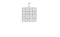
- FIG. 2 is a diagram schematically showing the configuration of the filter array according to Embodiment 1 of the present invention.
- FIG. 3 is a diagram showing an example of transmittance characteristics of each filter according to Embodiment 1 of the present invention.
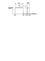
- FIG. 4 is a diagram showing the relationship between the transmittance characteristics of the optical filter according to Embodiment 1 of the present invention and the first wavelength light emitted by the first light source unit.
- FIG. 5 is a block diagram showing a functional configuration of the imaging apparatus according to Embodiment 2 of the present invention.
- FIG. 1 is a block diagram showing a functional configuration of the imaging apparatus according to Embodiment 1 of the present invention.
- FIG. 2 is a diagram schematically showing the configuration of the filter array according to Embodiment 1 of the present invention.
- FIG. 3 is a diagram showing an example of transmittance characteristics of each filter according to Em
- FIG. 6 shows the relationship between the transmittance characteristics of the optical filter of the imaging apparatus according to Embodiment 2 of the present invention, the first wavelength light emitted by the first light source unit, and the second wavelength light emitted by the second light source unit.
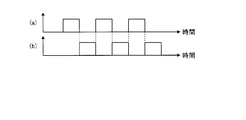
- FIG. FIG. 7 is a diagram illustrating a timing chart of light emission timings of the first light source unit and the second light source unit by the illumination control unit of the imaging apparatus according to Embodiment 2 of the present invention.
- FIG. 8 is a diagram illustrating a timing chart of light emission timings of the first light source unit and the second light source unit by the illumination control unit of the imaging apparatus according to the modification of the second embodiment of the present invention.
- FIG. 9 is a block diagram showing a functional configuration of the imaging apparatus according to Embodiment 3 of the present invention.
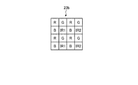
- FIG. 10 is a diagram schematically showing the configuration of the filter array of the imaging apparatus according to Embodiment 3 of the present invention.
- FIG. 11 is a diagram illustrating an example of transmittance characteristics of each filter of the imaging apparatus according to Embodiment 3 of the present invention.
- FIG. 12 is a diagram illustrating an example of transmittance characteristics of the optical filter of the imaging apparatus according to Embodiment 3 of the present invention.
- FIG. 13 is a timing chart of light emission timings of the first light source unit and the second light source unit by the illumination control unit of the imaging apparatus according to Embodiment 3 of the present invention.
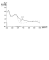
- FIG. 14 is a diagram showing absorption characteristics of hemoglobin in blood.
- FIG. 1 is a block diagram showing a functional configuration of the imaging apparatus according to Embodiment 1 of the present invention.
- An imaging device 1 shown in FIG. 1 captures a subject and generates image data of the subject, and is detachable from the body 2 and has a predetermined wavelength band toward the imaging region of the imaging device 1.
- the irradiation part 3 which irradiates the light which has these.
- the main body 2 includes an optical system 21, an image sensor 22, a filter array 23, an optical filter 24, an A / D conversion unit 25, an accessory communication unit 26, a display unit 27, a recording unit 28, and a control. Unit 29.
- the optical system 21 is configured by using one or a plurality of lenses, for example, a focus lens, a zoom lens, a squeeze and a shutter, and forms a subject image on the light receiving surface of the image sensor 22.
- the image sensor 22 receives the subject image that has passed through the optical filter 24 and the filter array 23 and performs photoelectric conversion to continuously generate image data according to a predetermined frame (for example, 60 fps).
- the imaging device 22 is a CMOS (Complementary Metal Oxide Semiconductor) that generates an electrical signal by photoelectrically converting light received by light transmitted through the optical filter 24 and the filter array 23 by each of a plurality of pixels arranged in a two-dimensional manner. Alternatively, it is configured using a CCD (Charge Coupled Device) or the like.
- the filter array 23 is disposed on the light receiving surface of the image sensor 22.
- the filter array 23 includes a plurality of visible light filters having different transmission spectrum maximum values in the visible light band, and a non-visible light filter having a transmission spectrum maximum value in a non-visible light region longer than the visible light region. Are arranged in correspondence with a plurality of pixels in the image sensor 22.
- FIG. 2 is a diagram schematically showing the configuration of the filter array 23.
- the filter array 23 is disposed on the light receiving surface of each pixel constituting the imaging device 22, and includes a visible light filter R that transmits red light and a visible light filter G that transmits green light.
- a unit including a visible light filter B that transmits blue light and a non-visible light filter IR that transmits non-visible light is disposed corresponding to a plurality of pixels.
- the pixel in which the visible light filter R is disposed is the R pixel
- the pixel in which the visible light filter G is disposed is the G pixel
- the pixel in which the visible light filter B is disposed is the B pixel
- the invisible light filter IR A pixel in which is arranged will be described as an IR pixel.
- FIG. 3 is a diagram showing an example of transmittance characteristics of each filter.
- the horizontal axis indicates the wavelength (nm) and the vertical axis indicates the transmittance.
- the curve LR indicates the transmittance of the visible light filter R
- the curve LG indicates the transmittance of the visible light filter G
- the curve LB indicates the transmittance of the visible light filter B
- the curve LIR is invisible.
- the transmittance of the optical filter IR is shown.
- the transmittance characteristics of each filter will be described for the sake of simplification, but each pixel (R pixel, G pixel, B pixel, and IR pixel) when each filter is provided for each pixel. This is the same as the spectral sensitivity characteristic.
- the visible light filter R has the maximum value of the transmission spectrum in the visible light band. Specifically, the visible light filter R has the maximum value of the transmission spectrum in the wavelength band 620 to 750 nm, transmits light in the wavelength band 620 to 750 nm, and has a wavelength band of 850 to 950 nm in the invisible light range. Part of the light is also transmitted.
- the visible light filter G has the maximum value of the transmission spectrum in the visible light band. Specifically, the visible light filter G has the maximum value of the transmission spectrum in the wavelength band 495 to 570 nm, transmits light in this wavelength band 495 to 570 nm, and has a wavelength band 850 to 950 nm in the invisible light range. Part of the light is also transmitted.
- the visible light filter B has the maximum value of the transmission spectrum in the visible light band. Specifically, the visible light filter B has a maximum value of a transmission spectrum in a wavelength band of 450 to 495 nm, transmits light in this wavelength band of 450 to 495 nm, and has a wavelength band of 850 to 950 nm in a non-visible light range. Part of the light is also transmitted.
- the invisible light filter IR has the maximum value of the transmission spectrum in the invisible light band, and transmits light in the wavelength band of 850 to 950 nm.
- the optical filter 24 is disposed in front of the filter array 23, and includes a first wavelength band including the maximum values of the transmission spectra of the visible light filter R, the visible light filter G, and the visible light filter B, and the transmission spectrum of the invisible light filter IR.
- the light having the wavelength included in any of the second wavelength bands including the maximum value of is transmitted.
- the A / D conversion unit 25 converts analog image data input from the image sensor 22 into digital image data and outputs the digital image data to the control unit 29.
- the accessory communication unit 26 transmits a drive signal to the accessory connected to the main unit 2 according to a predetermined communication standard under the control of the control unit 29.
- the display unit 27 displays an image corresponding to the image data input from the control unit 29.
- the display unit 27 is configured using a display panel such as liquid crystal or organic EL (Electro Luminescence).
- the recording unit 28 records various information related to the imaging device 1.
- the recording unit 28 records the image data generated by the image sensor 22, various programs related to the imaging device 1, parameters related to the process being executed, and the like.
- the recording unit 28 is configured using an SDRAM (Synchronous Dynamic Random Access Memory), a flash memory, a recording medium, and the like.
- the control unit 29 comprehensively controls the operation of the imaging apparatus 1 by giving instructions to each unit constituting the imaging apparatus 1 and transferring data.
- the control unit 29 is configured using a CPU (Central Processing Unit) or the like.
- the control unit 29 includes at least an image processing unit 291, a vital information generation unit 292, and an illumination control unit 293.
- the image processing unit 291 performs predetermined image processing on the image data input from the A / D conversion unit 25.
- the predetermined image processing includes optical black subtraction processing, white balance adjustment processing, image data synchronization processing, color matrix calculation processing, ⁇ correction processing, color reproduction processing, edge enhancement processing, and the like.
- the vital information generation unit 292 generates vital information of the subject based on the image signal corresponding to the IR pixel included in the image data continuously input from the A / D conversion unit 25.
- vital information is any one or more of oxygen saturation, heart rate, heart rate variability, stress, skin moisture, and blood pressure.
- the illumination control unit 293 controls light emission of the irradiation unit 3 connected to the main body unit 2 via the accessory communication unit 26.
- the illumination control unit 293 performs imaging of the imaging element 22 when the irradiation unit 3 is connected to the main body unit 2.
- the irradiation unit 3 is irradiated with light in synchronization with the timing.
- the irradiation unit 3 includes a communication unit 31 and a first light source unit 32.
- the communication unit 31 outputs the drive signal input from the accessory communication unit 26 of the main body unit 2 to the first light source unit 32.
- the first light source unit 32 is light having a wavelength within the range of the second wavelength band transmitted by the optical filter 24 in accordance with the drive signal input from the main body unit 2 via the communication unit 31, and the second wavelength.
- Light of a first wavelength (hereinafter referred to as “first wavelength light”) having a half width less than half of the band is irradiated toward the subject.
- the first light source unit 32 is configured using a light emitting LED (Light Emitting Diode).
- the imaging apparatus 1 configured as described above captures the subject while irradiating the subject with the first wavelength light, thereby obtaining color image data (image signals of the R pixel, G pixel, and B pixel) and vital information of the subject.
- Image data IR pixel image signal (near-infrared image data)) is generated.
- FIG. 4 is a diagram illustrating the relationship between the transmittance characteristics of the optical filter 24 and the first wavelength light emitted by the first light source unit 32.
- the horizontal axis indicates the wavelength (nm) and the vertical axis indicates the transmittance.
- the polygonal line LF indicates the transmittance characteristic of the optical filter 24, and the curve L ⁇ b> 1 indicates the wavelength band of the first wavelength light irradiated by the first light source unit 32.
- the optical filter 24 includes a first wavelength band W1 including the transmission spectra of the visible light filter R, the visible light filter G, and the visible light filter B, and a second wavelength of the transmission spectrum of the invisible light filter IR. Only light having a wavelength included in any of the bands W2 is transmitted. Specifically, the optical filter 24 transmits light of 400 to 760 nm in the visible light region, and transmits light of 850 to 950 nm in the non-visible light region. Further, as indicated by the curve L1, the first light source unit 32 is a first wavelength light having a half-value width within the second wavelength band W2 of the optical filter 24 and not more than half of the second wavelength band W2. Irradiate.
- the first light source unit 32 emits light of 860 to 900 nm.
- the optical filter 24 transmits light of 400 to 760 nm in the visible light region and transmits light of 850 to 950 nm in the non-visible light region. At least a part of light having a wavelength band of ⁇ 850 nm may be transmitted (at least a part of the light is not transmitted).
- the optical filter 24 may transmit light having a part of a wavelength band of at least 770 to 800 nm.
- the first light source unit 32 is in the range of the second wavelength band W2 in the optical filter 24 and has a half width less than or equal to half of the second wavelength band W2. Since the first wavelength light is emitted, it is possible to acquire image data for generating vital information of the subject in a non-contact state.
- the optical filter 24 includes the first wavelength band including the transmission spectra of the visible light filter R, the visible light filter G, and the visible light filter B, and the transmission spectrum of the non-visible light filter IR. Since unnecessary information (wavelength component) is removed by transmitting light having a wavelength including any one of the second wavelength bands including, the accuracy in the visible light region can be improved (high resolution) and invisible The degree of freedom of the light source used in the light region can be improved.
- the first light source unit 32 irradiates light of 860 to 900 nm as the first wavelength light.
- You may comprise using light emitting LED which can irradiate light.
- an optical filter 24 capable of transmitting light in the visible light band of 900 to 1000 nm as the second wavelength band may be used.
- the vital information generation unit 292 is based on IR pixels in image data (hereinafter referred to as “moving image data”) of the image sensor 22 continuously input from the A / D conversion unit 25.
- the color change of the subject's skin is detected based on the image signal of the subject, and the heart rate / heart rate variation of the subject is detected based on the image signal of each of the R pixel, the G pixel, and the B pixel in the moving image data.
- An accurate heartbeat of the subject may be detected based on the detected heartbeat and heartbeat variation of the subject and the above-described skin color variation.
- the vital information generation unit 292 may detect the stress level of the subject from the above-described waveform of heartbeat variability as vital information.
- the irradiation unit 3 is detachable from the main body unit 2, but the irradiation unit 3 and the main body unit 2 may be formed integrally.
- the imaging device according to the second embodiment is different in configuration from the imaging device 1 according to the first embodiment described above.
- the imaging apparatus according to the second embodiment is different in configuration from the irradiation unit 3 of the imaging apparatus 1 according to the first embodiment described above.
- symbol is attached
- FIG. 5 is a block diagram showing a functional configuration of the imaging apparatus according to Embodiment 2 of the present invention.
- An imaging apparatus 1a illustrated in FIG. 5 includes an irradiation unit 3a instead of the main body unit 2 and the irradiation unit 3 of the imaging apparatus 1 according to Embodiment 1 described above.
- the irradiation unit 3a irradiates light having a predetermined wavelength band toward the imaging region of the imaging device 1a.
- the irradiation unit 3a further includes a second light source unit 33.
- the second light source unit 33 is light having a wavelength within the range of the second wavelength band in the optical filter 24, has a half-value width less than half of the second wavelength band, and is different from the first wavelength light.
- Light with a wavelength hereinafter referred to as “second wavelength light” is irradiated toward the subject.
- the 2nd light source part 33 is comprised using light emitting LED.
- FIG. 6 is a diagram illustrating the relationship between the transmittance characteristics of the optical filter 24, the light in the first wavelength band irradiated by the first light source unit 32, and the light in the second wavelength band irradiated by the second light source unit 33.
- the horizontal axis indicates the wavelength (nm) and the vertical axis indicates the transmittance.
- the polygonal line LF indicates the transmittance characteristic of the optical filter 24
- the curve L ⁇ b> 1 indicates the wavelength band of the first wavelength light irradiated by the first light source unit 32
- the curve L ⁇ b> 2 is determined by the second light source unit 33. The wavelength band of the irradiated second wavelength light is shown.
- the optical filter 24 is one of the light in the first wavelength band W1 of the visible light filter R, the visible light filter G, and the visible light filter B and the second wavelength band W2 of the invisible light filter IR. Transmits light having a wavelength including.
- the first light source unit 32 is a first wavelength light having a half-value width within a range of the second wavelength band transmitted by the optical filter 24 and not more than half of the second wavelength band. Irradiate.
- the second light source unit 33 is a second wavelength light having a half-value width within a range of the second wavelength band transmitted through the optical filter 24 and not more than half of the second wavelength band. Irradiate.
- the second light source unit 33 irradiates the second wavelength light having a wavelength band different from the light of the first wavelength band irradiated by the first light source unit 32. Specifically, the second light source unit 33 irradiates light of 900 to 950 nm.
- FIG. 7 is a timing chart of the light emission timings of the first light source unit 32 and the second light source unit 33 by the illumination control unit 293.
- the horizontal axis indicates time.
- 7A shows the light emission timing of the first light source unit 32
- FIG. 7B shows the light emission timing of the second light source unit 33.
- the illumination control unit 293 causes the first light source unit 32 and the second light source unit 33 to alternately emit light through the accessory communication unit 26 and the communication unit 31, thereby causing the first wavelength light and the first light source unit to emit light.
- Two-wavelength light is irradiated toward the subject in a time-sharing manner. Thereby, in addition to the first wavelength light, information on the second wavelength light can be obtained.
- the light within the range of the second wavelength band in the optical filter 24 has a half width less than half of the second wavelength band, and the first wavelength light
- the second light source unit 33 that irradiates the subject with different second wavelength light is further provided, and the illumination control unit 293 alternately irradiates the first light source unit 32 and the second light source unit 33, so that vital information is obtained. It is possible to obtain spatial information and distance information of a three-dimensional map by 3D pattern projection.
- the illumination control unit 293 causes the first light source unit 32 and the second light source unit 33 to emit light alternately. For example, a predetermined number of frames of image data generated by the image sensor 22 is used. The light emission timing may be changed every time.
- FIG. 8 is a view showing a timing chart of the light emission timings of the first light source unit 32 and the second light source unit 33 by the illumination control unit 293 according to the modification of the second embodiment of the present invention.
- the horizontal axis indicates time.
- 8A shows the light emission timing of the first light source unit 32
- FIG. 8B shows the light emission timing of the second light source unit 33.
- the illumination control unit 293 synchronizes the first light source unit 32 with the frame rate of the image sensor 22 via the accessory communication unit 26 and the communication unit 31, and the first light source unit 32 in a predetermined pattern. And the 2nd light source part 33 is light-emitted. Specifically, the illumination control unit 293 causes the first light source unit 32 to emit light a predetermined number of times, for example, three times, and then causes the second light source unit 33 to emit light once. Thereby, in addition to the first wavelength light, information on the second wavelength light can also be obtained.
- vital information can be obtained and spatial information and distance information of a three-dimensional map by 3D pattern projection can be obtained.
- the illumination control unit 293 changes the light emission timing for each number of frames of the image sensor 22, but for example, the light emission of the first light source unit 32 and the second light source unit 33 You may make it change time. Specifically, the illumination control unit 293 causes the second light source unit 33 to be shorter than the first predetermined time after causing the first light source unit 32 to emit light for the first predetermined time, for example, for 30 seconds. You may make it perform repeatedly the operation
- the imaging device according to the third embodiment is different in configuration from the imaging device 1a according to the second embodiment described above. Specifically, the imaging apparatus according to Embodiment 3 has a different color filter configuration. Therefore, in the following, after the imaging apparatus according to the third embodiment is described, processing executed by the third embodiment will be described.
- symbol is attached
- FIG. 9 is a block diagram showing a functional configuration of the imaging apparatus according to Embodiment 3 of the present invention.
- An imaging apparatus 1b shown in FIG. 9 includes a filter array 23b instead of the filter array 23 of the imaging apparatus 1a according to the second embodiment described above.
- the filter array 23b includes a plurality of visible light filters having different transmission spectrum maximum values in the visible light band, a non-visible light region longer than the visible light region, and a transmission spectrum in the non-visible light region. And a plurality of invisible light filters having different maximum values.
- FIG. 10 is a diagram schematically showing the configuration of the filter array 23b.
- the filter array 23b includes a visible light filter R, a visible light filter G, a visible light filter B, a first invisible light filter IR1 that transmits invisible light, and a first non-visible light filter IR1.
- a unit including a second invisible light filter IR2 that transmits invisible light different from the visible light filter IR1 is disposed in association with a plurality of pixels.
- a pixel in which the first invisible light filter IR1 is disposed is described as a first IR pixel
- a pixel in which the second invisible light filter IR2 is disposed is described as a second IR pixel.
- FIG. 11 is a diagram showing an example of transmittance characteristics of each filter.
- FIG. 12 is a diagram illustrating an example of the transmittance characteristic of the optical filter 24. 11 and 12, the horizontal axis indicates the wavelength (nm), and the horizontal axis indicates the transmittance.
- the curve LR indicates the transmittance of the visible light filter R
- the curve LG indicates the transmittance of the visible light filter G
- the curve LB indicates the transmittance of the visible light filter B
- the curve LIR1 is the first.
- the transmittance of the invisible light filter IR1 is shown
- the curve LIR2 shows the transmittance of the second invisible light filter IR2.
- the first invisible light filter IR1 has the maximum value of the transmission spectrum in the invisible light band, and transmits light in the wavelength band of 850 to 950 nm.
- the second invisible light filter IR2 has the maximum value of the transmission spectrum in the invisible light band, and transmits light in the wavelength band of 850 to 950 nm.
- FIG. 13 is a timing chart of the light emission timings of the first light source unit 32 and the second light source unit 33 by the illumination control unit 293.
- the horizontal axis indicates time.
- (a) of FIG. 13 shows the light emission timing of the 1st light source part 32
- (b) of FIG. 13 shows the light emission timing of the 2nd light source part.
- the illumination control unit 293 causes the first light source unit 32 and the second light source unit 33 to emit light simultaneously via the accessory communication unit 26 and the communication unit 31, so that the first wavelength light and the second wavelength light are emitted. Light is directed toward the subject at the same time. Thereby, the information of 1st wavelength light and 2nd wavelength light can be obtained simultaneously.
- the illumination control unit 293 simultaneously irradiates the first light source unit 32 and the second light source unit 33, vital information and spatial information of a three-dimensional map by 3D pattern projection. And distance information can be obtained simultaneously.
- Embodiment 3 of the present invention vital information and spatial information and distance information of a three-dimensional map by 3D pattern projection are acquired at the same time.
- oxygen saturation in blood may be acquired as vital information. Good.
- FIG. 14 is a diagram showing absorption characteristics of hemoglobin in blood.
- the horizontal axis indicates the wavelength (nm), and the vertical axis indicates the molar absorption coefficient (cm ⁇ 1 / m).
- a curve L10 indicates the molar absorption coefficient of oxyhemoglobin, and a curve L11 indicates the molar absorption coefficient of reduced hemoglobin.
- Hb reduced hemoglobin
- HbO 2 oxidized hemoglobin
- SPO 2 oxygen saturation
- the difference in absorption characteristics for each wavelength of oxyhemoglobin and reduced hemoglobin is used. That is, as shown in FIG. 14, in the modification of the third embodiment, the first light source unit 32 emits light of 940 nm in the near infrared region, and the second light source unit 33 has 1000 nm of infrared region. Light is irradiated, and the vital information generation unit 292 calculates oxygen saturation based on the image signals of the first IR pixel and the second IR pixel included in the image data (note that the principle method of oxygen saturation is Refer to Patent Document 1. Or non-contact oxygen saturation method (Lingqin Kong et al., “Non-contact detection of oxygen saturation based on visible light imaging device”. using ambient light ”, Optics Express, Vol. 21, Issue 15, pp. 17464-17471 (2013)).
- the first light source unit or the second light source unit is configured using the light emitting LED.
- light in the visible light wavelength band and the near-infrared wavelength band is used like a halogen light source. You may comprise using the light source to irradiate.
- the primary color filters of the visible light filter R, the visible light filter G, and the visible light filter B are used as the visible light filter.
- complementary color filters such as magenta, cyan, and yellow are used. May be used.
- the optical system, the optical filter, the filter array, and the image sensor are incorporated in the main body.
- the optical system, the optical filter, the filter array, and the image sensor are accommodated in the unit.
- the unit may be detachable from the main body.
- the optical system may be accommodated in a lens barrel, and the lens barrel may be configured to be detachable from a unit that accommodates an optical filter, a filter array, and an image sensor.
- the vital information generation unit is provided in the main body.
- a function capable of generating vital information in a wearable device such as a glasses or a portable device capable of bidirectional communication. May be realized by a program or application software, and the vital information of the subject may be generated by the portable device or the wearable device by transmitting the image data generated by the imaging device.
- a subject in addition to the imaging device used in the description of the present invention, a subject can be passed through an optical device such as a mobile device or wearable device equipped with an image sensor in a mobile phone or smartphone, a video camera, an endoscope, a surveillance camera, or a microscope.
- an optical device such as a mobile device or wearable device equipped with an image sensor in a mobile phone or smartphone, a video camera, an endoscope, a surveillance camera, or a microscope.
- the present invention can be applied to any device that can image a subject, such as an imaging device for imaging.
- each processing method by the imaging apparatus in the above-described embodiment can be stored as a program that can be executed by a control unit such as a CPU.
- a control unit such as a CPU
- it can be stored and distributed in a storage medium of an external storage device such as a memory card (ROM card, RAM card, etc.), magnetic disk, optical disk (CD-ROM, DVD, etc.), semiconductor memory, or the like.
- a control unit such as a CPU reads the program stored in the storage medium of the external storage device, and the operation described above can be executed by the operation being controlled by the read program.
- the present invention is not limited to the above-described embodiments and modifications as they are, and in the implementation stage, the constituent elements can be modified and embodied without departing from the spirit of the invention.
- Various inventions can be formed by appropriately combining a plurality of constituent elements disclosed in the above-described embodiments. For example, some constituent elements may be deleted from all the constituent elements described in the above-described embodiments and modifications. Furthermore, you may combine suitably the component demonstrated by each embodiment and the modification.
Landscapes
- Health & Medical Sciences (AREA)
- Life Sciences & Earth Sciences (AREA)
- Engineering & Computer Science (AREA)
- Physics & Mathematics (AREA)
- Surgery (AREA)
- General Health & Medical Sciences (AREA)
- Biophysics (AREA)
- Pathology (AREA)
- Biomedical Technology (AREA)
- Heart & Thoracic Surgery (AREA)
- Medical Informatics (AREA)
- Molecular Biology (AREA)
- Animal Behavior & Ethology (AREA)
- Public Health (AREA)
- Veterinary Medicine (AREA)
- Cardiology (AREA)
- Physiology (AREA)
- Signal Processing (AREA)
- Optics & Photonics (AREA)
- Multimedia (AREA)
- Radiology & Medical Imaging (AREA)
- Nuclear Medicine, Radiotherapy & Molecular Imaging (AREA)
- Vascular Medicine (AREA)
- Dermatology (AREA)
- Spectroscopy & Molecular Physics (AREA)
- Measurement Of The Respiration, Hearing Ability, Form, And Blood Characteristics Of Living Organisms (AREA)
- Measuring And Recording Apparatus For Diagnosis (AREA)
- Studio Devices (AREA)
- Instruments For Viewing The Inside Of Hollow Bodies (AREA)
- Endoscopes (AREA)
Abstract
非接触状態で生体のバイタル情報を得ることができる撮像装置を提供する。撮像装置1は、複数の可視光フィルタと、可視光帯域より長波長側の非可視光領域に透過スペクトルの最大値を有する非可視光フィルタと、を含むユニットを、撮像素子22の複数の画素に対応させて配置したフィルタアレイ23と、複数の可視光フィルタそれぞれの透過スペクトルを含む第1波長帯域および非可視光フィルタの透過スペクトルを含む第2波長帯域のいずれかに含まれる波長を有する光のみを透過する光学フィルタ24と、第2波長帯域の範囲内の光であって、第2波長帯域の半分以下の半値幅を有する第1波長の光を被写体に向けて照射する第1光源部32と、を備える。
Description
本発明は、被写体を撮像し、該被写体のバイタル情報を検出するために用いる画像データを生成するための撮像装置に関する。
従来、医療分野において、人間の健康状態を把握するための情報として、心拍数、酸素飽和度および血圧等のバイタル情報を用いて、被写体の健康状態を把握している。例えば、赤色の光および近赤外の光それぞれを照射する測定プローブ内に指等の生体を接触させた状態でイメージセンサによって撮像し、このイメージセンサによって生成された画像データに基づいて、生体の酸素飽和度を算出する技術が知られている(特許文献1参照)。この技術によれば、イメージセンサによって生成された画像データに応じて算出した生体による光の吸収度合いと、この光の吸収度合いの時間変化とに基づいて、生体の酸素飽和度を算出する。
しかしながら、上述した特許文献1では、生体が測定プローブに接触した状態でなければ、生体のバイタル情報を得ることができず、利便性が低かった。
本発明は、上記に鑑みてなされたものであって、非接触状態で生体のバイタル情報を得ることができる撮像装置を提供することを目的とする。
上述した課題を解決し、目的を達成するために、本発明に係る撮像装置は、被写体のバイタル情報を検出するための画像データを生成する撮像装置であって、二次元状に配置された複数の画素がそれぞれ受光した光を光電変換することによって前記画像データを生成する撮像素子と、可視光帯域内における透過スペクトルの最大値が互いに異なる複数の可視光フィルタと、前記可視光帯域より長波長側の非可視光領域に透過スペクトルの最大値を有する非可視光フィルタと、を含むユニットを、前記複数の画素に対応させて配置したフィルタアレイと、前記フィルタアレイの受光面に配置され、前記複数の可視光フィルタそれぞれの透過スペクトルの最大値を含む第1波長帯域および前記非可視光フィルタの透過スペクトルの最大値を含む第2波長帯域のいずれかに含まれる光を透過する光学フィルタと、前記第2波長帯域の範囲内の波長を有する光であって、前記第2波長帯域の半分以下の半値幅を有する第1波長の光を前記被写体に向けて照射する第1光源部と、を備えたことを特徴とする。
また、本発明に係る撮像装置は、上記発明において、前記第2波長帯域の範囲内の波長を有する光であって、前記第2波長帯域の半分以下の半値幅を有し、前記第1波長の光と異なる第2波長の光を前記被写体に向けて照射する第2光源部と、前記第1光源部および前記第2光源部それぞれの照射タイミングを制御する照明制御部と、をさらに備えたことを特徴とする。
また、本発明に係る撮像装置は、上記発明において、前記照明制御部は、前記第1光源部と前記第2光源部とを所定のパターンで交互に照射させることを特徴とする。
また、本発明に係る撮像装置は、上記発明において、前記非可視光フィルタは、前記第1波長の光を透過する第1非可視光フィルタと、前記第2波長の光を透過する第2非可視光フィルタと、を有し、前記照明制御部は、前記第1光源部および前記第2光源部それぞれを同時に照射させることを特徴とする。
また、本発明に係る撮像装置は、上記発明において、前記第1光源部および前記第2光源部は、当該撮像装置の本体部に対して着脱自在であることを特徴とする。
また、本発明に係る撮像装置は、上記発明において、前記撮像素子が生成した前記画像データを用いて前記バイタル情報を生成するバイタル情報生成部をさらに備えたことを特徴とする。
本発明によれば、非接触状態で生体のバイタル情報を得ることができるという効果を奏する。
以下、本発明を実施するための形態を図面とともに詳細に説明する。なお、以下の実施の形態により本発明が限定されるものではない。また、以下の説明において参照する各図は、本発明の内容を理解でき得る程度に形状、大きさ、および位置関係を概略的に示してあるに過ぎない。即ち、本発明は、各図で例示された形状、大きさ、および位置関係のみに限定されるものではない。また、同一の構成には同一の符号を付して説明する。
(実施の形態1)
〔撮像装置の構成〕
図1は、本発明の実施の形態1に係る撮像装置の機能構成を示すブロック図である。図1に示す撮像装置1は、被写体を撮像し、被写体の画像データを生成する本体部2と、本体部2に対して着脱自在であり、撮像装置1の撮像領域に向けて所定の波長帯域を有する光を照射する照射部3と、を備える。
〔撮像装置の構成〕
図1は、本発明の実施の形態1に係る撮像装置の機能構成を示すブロック図である。図1に示す撮像装置1は、被写体を撮像し、被写体の画像データを生成する本体部2と、本体部2に対して着脱自在であり、撮像装置1の撮像領域に向けて所定の波長帯域を有する光を照射する照射部3と、を備える。
〔本体部の構成〕
まず、本体部2の構成について説明する。
本体部2は、光学系21と、撮像素子22と、フィルタアレイ23と、光学フィルタ24と、A/D変換部25と、アクセサリー通信部26と、表示部27と、記録部28と、制御部29と、を備える。
まず、本体部2の構成について説明する。
本体部2は、光学系21と、撮像素子22と、フィルタアレイ23と、光学フィルタ24と、A/D変換部25と、アクセサリー通信部26と、表示部27と、記録部28と、制御部29と、を備える。
光学系21は、一または複数のレンズ、例えばフォーカスレンズやズームレンズ、しぼりおよびシャッタ等を用いて構成され、被写体像を撮像素子22の受光面に結像する。
撮像素子22は、光学フィルタ24およびフィルタアレイ23を透過した被写体像を受光して光電変換を行うことによって、画像データを所定のフレーム(例えば60fps)に従って連続的に生成する。撮像素子22は、二次元状に配置された複数の画素の各々が光学フィルタ24およびフィルタアレイ23を透過した光を受光した光を光電変換し、電気信号を生成するCMOS(Complementary Metal Oxide Semiconductor)またはCCD(Charge Coupled Device)等を用いて構成される。
フィルタアレイ23は、撮像素子22の受光面に配置される。フィルタアレイ23は、可視光帯域内における透過スペクトルの最大値が互いに異なる複数の可視光フィルタと、可視光領域より長波長側の非可視光領域に透過スペクトルの最大値を有する非可視光フィルタと、を含むユニットを、撮像素子22における複数の画素に対応させて配置される。
図2は、フィルタアレイ23の構成を模式的に示す図である。図2に示すように、フィルタアレイ23は、撮像素子22を構成する各画素の受光面に配置され、赤色の光を透過する可視光フィルタRと、緑色の光を透過する可視光フィルタGと、青色の光を透過する可視光フィルタBと、非可視光の光を透過する非可視光フィルタIRと、を含むユニットを複数の画素に対応させて配置している。なお、以下においては、可視光フィルタRが配置された画素をR画素、可視光フィルタGが配置された画素をG画素、可視光フィルタBが配置された画素をB画素および非可視光フィルタIRが配置された画素をIR画素として説明する。
図3は、各フィルタの透過率特性の一例を示す図である。図3において、横軸が波長(nm)を示し、縦軸が透過率を示す。また、図3において、曲線LRが可視光フィルタRの透過率を示し、曲線LGが可視光フィルタGの透過率を示し、曲線LBが可視光フィルタBの透過率を示し、曲線LIRが非可視光フィルタIRの透過率を示す。なお、図3においては、説明を簡略化するため、各フィルタの透過率特性について説明するが、画素毎に各フィルタを設けた場合における各画素(R画素、G画素、B画素およびIR画素)の分光感度特性と同じである。
図3に示すように、可視光フィルタRは、可視光帯域に透過スペクトルの最大値を有する。具体的には、可視光フィルタRは、波長帯域620~750nmに透過スペクトルの最大値を有し、この波長帯域620~750nmの光を透過するとともに、非可視光域の波長帯域850~950nmの光の一部も透過する。可視光フィルタGは、可視光帯域に透過スペクトルの最大値を有する。具体的には、可視光フィルタGは、波長帯域495~570nmに透過スペクトルの最大値を有し、この波長帯域495~570nmの光を透過するとともに、非可視光域の波長帯域850~950nmの光の一部も透過する。可視光フィルタBは、可視光帯域に透過スペクトルの最大値を有する。具体的には、可視光フィルタBは、波長帯域450~495nmに透過スペクトルの最大値を有し、この波長帯域450~495nmの光を透過するとともに、非可視光域の波長帯域850~950nmの光の一部も透過する。非可視光フィルタIRは、非可視光帯域に透過スペクトルの最大値を有し、波長帯域850~950nmの光を透過する。
図1に戻り、本体部2の構成の説明を続ける。
光学フィルタ24は、フィルタアレイ23の前面に配置され、可視光フィルタR、可視光フィルタGおよび可視光フィルタBそれぞれの透過スペクトルの最大値を含む第1波長帯域および非可視光フィルタIRの透過スペクトルの最大値を含む第2波長帯域のいずれに含まれる波長を有する光を透過する。
光学フィルタ24は、フィルタアレイ23の前面に配置され、可視光フィルタR、可視光フィルタGおよび可視光フィルタBそれぞれの透過スペクトルの最大値を含む第1波長帯域および非可視光フィルタIRの透過スペクトルの最大値を含む第2波長帯域のいずれに含まれる波長を有する光を透過する。
A/D変換部25は、撮像素子22から入力されたアナログの画像データをデジタルの画像データに変換して制御部29へ出力する。
アクセサリー通信部26は、制御部29の制御のもと、所定の通信規格に従って、本体部2に接続されるアクセサリーに対して駆動信号を送信する。
表示部27は、制御部29から入力される画像データに対応する画像を表示する。表示部27は、液晶または有機EL(Electro Luminescence)等の表示パネルを用いて構成される。
記録部28は、撮像装置1に関する各種情報を記録する。記録部28は、撮像素子22が生成した画像データおよび撮像装置1に関する各種プログラムや実行中の処理に関するパラメータ等を記録する。記録部28は、SDRAM(Synchronous Dynamic Random Access Memory)、Flashメモリおよび記録媒体等を用いて構成される。
制御部29は、撮像装置1を構成する各部に対する指示やデータの転送等を行うことによって、撮像装置1の動作を統括的に制御する。制御部29は、CPU(Central Processing Unit)等を用いて構成される。
ここで、制御部29の詳細な構成について説明する。制御部29は、少なくとも、画像処理部291と、バイタル情報生成部292と、照明制御部293と、を有する。
画像処理部291は、A/D変換部25から入力される画像データに対して、所定の画像処理を行う。ここで、所定の画像処理とは、オプティカルブラック減算処理、ホワイトバランス調整処理、画像データの同時化処理、カラーマトリクス演算処理、γ補正処理、色再現処理およびエッジ強調処理等である。
バイタル情報生成部292は、A/D変換部25から連続的に入力される画像データに含まれるIR画素に対応する画像信号に基づいて、被写体のバイタル情報を生成する。ここで、バイタル情報とは、酸素飽和度、心拍、心拍変動、ストレス、肌水分および血圧のいずれか1つ以上である。
照明制御部293は、アクセサリー通信部26を介して本体部2に接続された照射部3の発光を制御する。例えば、照明制御部293は、撮像装置1に被写体のバイタル情報を生成するバイタル情報生成モードが設定されている場合において、本体部2に照射部3が接続されているとき、撮像素子22の撮像タイミングに同期して照射部3に光を照射させる。
〔照射部の構成〕
次に、照射部3の構成について説明する。照射部3は、通信部31と、第1光源部32と、を備える。
次に、照射部3の構成について説明する。照射部3は、通信部31と、第1光源部32と、を備える。
通信部31は、本体部2のアクセサリー通信部26から入力された駆動信号を第1光源部32へ出力する。
第1光源部32は、通信部31を介して本体部2から入力される駆動信号に従って、光学フィルタ24が透過する第2波長帯域の範囲内の波長を有する光であって、この第2波長帯域の半分以下の半値幅を有する第1波長の光(以下、「第1波長光」という)を被写体に向けて照射する。第1光源部32は、発光LED(Light Emitting Diode)を用いて構成される。
このように構成された撮像装置1は、被写体に対して第1波長光を照射しながら撮像することによって、被写体のカラー画像データ(R画素、G画素およびB画素それぞれの画像信号)およびバイタル情報を得るための画像データ(IR画素の画像信号(近赤外の画像データ))を生成する。
次に、上述した光学フィルタ24と第1光源部32が照射する第1波長光との関係について説明する。図4は、光学フィルタ24の透過率特性と第1光源部32が照射する第1波長光との関係を示す図である。図4において、横軸が波長(nm)を示し、縦軸が透過率を示す。また、図4において、折れ線LFが光学フィルタ24の透過率特性を示し、曲線L1が第1光源部32によって照射された第1波長光の波長帯域を示す。
図4に示すように、光学フィルタ24は、可視光フィルタR、可視光フィルタGおよび可視光フィルタBそれぞれの透過スペクトルを含む第1波長帯域W1および非可視光フィルタIRの透過スペクトルの第2波長帯域W2のいずれかに含まれる波長を有する光のみを透過する。具体的には、光学フィルタ24は、可視光領域において400~760nmの光を透過するとともに、非可視光領域において850~950nmの光を透過する。また、曲線L1に示すように、第1光源部32は、光学フィルタ24における第2波長帯域W2の範囲内であって、この第2波長帯域W2の半分以下の半値幅を有する第1波長光を照射する。具体的には、第1光源部32は、860~900nmの光を照射する。これにより、可視光のカラー画像データおよびバイタル情報を得るための非可視光の画像データそれぞれを取得することができる。なお、図4においては、説明を簡略するため、光学フィルタ24を可視光領域において400~760nmの光を透過するとともに、非可視光領域において850~950nmの光を透過していたが、もちろん760~850nmの波長帯域を有する光に対して、少なくとも一部を透過させてもよい(少なくとも一部を透過させない)。例えば、光学フィルタ24は、少なくとも770~800nmの波長帯域の一部を有する光を透過させてもよい。
以上説明した本発明の実施の形態1によれば、第1光源部32が光学フィルタ24における第2波長帯域W2の範囲内であって、この第2波長帯域W2の半分以下の半値幅を有する第1波長光を照射するので、非接触状態で被写体のバイタル情報を生成するための画像データを取得することができる。
また、本発明の実施の形態1によれば、光学フィルタ24が可視光フィルタR、可視光フィルタGおよび可視光フィルタBそれぞれの透過スペクトルを含む第1波長帯域および非可視光フィルタIRの透過スペクトルを含む第2波長帯域のいずれかを含む波長を有する光を透過することによって、不要な情報(波長成分)を除去するので、可視光領域の精度向上を実現(高解像度)できるとともに、非可視光領域の使用光源の自由度を向上させることができる。
また、本発明の実施の形態1では、第1光源部32は、第1波長光として860~900nmの光を照射していたが、例えば生体のバイタル情報として肌水分を検出する場合、970nmの光を照射可能な発光LEDを用いて構成してもよい。このとき、第2波長帯域として900~1000nmの可視光帯域の光を透過可能な光学フィルタ24を用いればよい。
また、本発明の実施の形態1では、バイタル情報生成部292は、A/D変換部25から連続的に入力される撮像素子22の画像データ(以下、「動画データ」という)におけるIR画素からの画像信号に基づいて、被写体の皮膚の色の変動を検出するとともに、動画データにおけるR画素、G画素およびB画素それぞれの画像信号に基づいて、被写体の心拍・心拍変動を検出するとともに、この検出した被写体の心拍・心拍変動と上述した皮膚の色の変動とに基づいて、被写体の正確な心拍を検出するようにしてもよい。さらに、バイタル情報生成部292は、バイタル情報として、上述した心拍変動の波形から被検体のストレス具合を検出するようにしてもよい。
また、本発明の実施の形態1では、照射部3が本体部2に対して着脱自在であったが、照射部3と本体部2とを一体的に形成してもよい。
(実施の形態2)
次に、本発明の実施の形態2について説明する。本実施の形態2に係る撮像装置は、上述した実施の形態1に係る撮像装置1と構成が異なる。具体的には、本実施の形態2に係る撮像装置は、上述した実施の形態1に係る撮像装置1の照射部3と構成が異なる。このため、以下においては、本実施の形態2に係る撮像装置の照射部の構成を説明後、本実施の形態2に係る撮像装置が実行する処理について説明する。なお、上述した実施の形態1に係る撮像装置1と同一の構成には同一の符号を付して説明を省略する。
次に、本発明の実施の形態2について説明する。本実施の形態2に係る撮像装置は、上述した実施の形態1に係る撮像装置1と構成が異なる。具体的には、本実施の形態2に係る撮像装置は、上述した実施の形態1に係る撮像装置1の照射部3と構成が異なる。このため、以下においては、本実施の形態2に係る撮像装置の照射部の構成を説明後、本実施の形態2に係る撮像装置が実行する処理について説明する。なお、上述した実施の形態1に係る撮像装置1と同一の構成には同一の符号を付して説明を省略する。
〔撮像装置の構成〕
図5は、本発明の実施の形態2に係る撮像装置の機能構成を示すブロック図である。図5に示す撮像装置1aは、本体部2と、上述した実施の形態1に係る撮像装置1の照射部3に換えて、照射部3aを備える。
図5は、本発明の実施の形態2に係る撮像装置の機能構成を示すブロック図である。図5に示す撮像装置1aは、本体部2と、上述した実施の形態1に係る撮像装置1の照射部3に換えて、照射部3aを備える。
〔照射部の構成〕
照射部3aは、撮像装置1aの撮像領域に向けて所定の波長帯域を有する光を照射する。また、照射部3aは、上述した実施の形態1に係る照射部3の構成に加えて、第2光源部33をさらに備える。
照射部3aは、撮像装置1aの撮像領域に向けて所定の波長帯域を有する光を照射する。また、照射部3aは、上述した実施の形態1に係る照射部3の構成に加えて、第2光源部33をさらに備える。
第2光源部33は、光学フィルタ24における第2波長帯域の範囲内の波長を有する光であって、第2波長帯域の半分以下の半値幅を有し、第1波長の光と異なる第2波長の光(以下、「第2波長光」という)を被写体に向けて照射する。第2光源部33は、発光LEDを用いて構成される。
次に、上述した光学フィルタ24、第1光源部32が照射する第1波長帯域の光および第2光源部33が照射する第2波長帯域の光の関係について説明する。図6は、光学フィルタ24の透過率特性、第1光源部32が照射する第1波長帯域の光および第2光源部33が照射する第2波長帯域の光の関係を示す図である。図6において、横軸が波長(nm)を示し、縦軸が透過率を示す。また、図6において、折れ線LFが光学フィルタ24の透過率特性を示し、曲線L1が第1光源部32によって照射された第1波長光の波長帯域を示し、曲線L2が第2光源部33によって照射された第2波長光の波長帯域を示す。
図6に示すように、光学フィルタ24は、可視光フィルタR、可視光フィルタGおよび可視光フィルタBそれぞれの第1波長帯域W1の光および非可視光フィルタIRの第2波長帯域W2のいずれかを含む波長を有する光を透過する。また、曲線L1に示すように、第1光源部32は、光学フィルタ24が透過する第2波長帯域の範囲内であって、この第2波長帯域の半分以下の半値幅を有する第1波長光を照射する。さらに、曲線L2に示すように、第2光源部33は、光学フィルタ24が透過する第2波長帯域の範囲内であって、この第2波長帯域の半分以下の半値幅を有する第2波長光を照射する。さらに、第2光源部33は、第1光源部32が照射する第1波長帯域の光と異なる波長帯域を有する第2波長光を照射する。具体的には、第2光源部33は、900~950nmの光を照射する。
〔照明制御部による処理〕
次に、照明制御部293による第1光源部32および第2光源部33の発光タイミングについて説明する。図7は、照明制御部293による第1光源部32および第2光源部33の発光タイミングのタイミングチャートを示す図である。なお、図7において、横軸が時間を示す。また、図7の(a)が第1光源部32の発光タイミングを示し、図7の(b)が第2光源部33の発光タイミングを示す。
次に、照明制御部293による第1光源部32および第2光源部33の発光タイミングについて説明する。図7は、照明制御部293による第1光源部32および第2光源部33の発光タイミングのタイミングチャートを示す図である。なお、図7において、横軸が時間を示す。また、図7の(a)が第1光源部32の発光タイミングを示し、図7の(b)が第2光源部33の発光タイミングを示す。
図7に示すように、照明制御部293は、アクセサリー通信部26および通信部31を介して第1光源部32および第2光源部33それぞれを交互に発光させることによって、第1波長光と第2波長光とを時分割で被写体に向けて照射させる。これにより、第1波長光以外に、第2波長光の情報を得ることができる。
以上説明した本発明の実施の形態2によれば、光学フィルタ24における第2波長帯域の範囲内の光であって、第2波長帯域の半分以下の半値幅を有し、第1波長光と異なる第2波長光を被写体に向けて照射する第2光源部33をさらに設け、照明制御部293が第1光源部32および第2光源部33それぞれを交互に照射させるので、バイタル情報を得ることができるとともに、3Dパターン投影による3次元マップの空間情報や距離情報を得ることができる。
(実施の形態2の変形例)
本発明の実施の形態2では、照明制御部293が第1光源部32および第2光源部33それぞれを交互に発光させていたが、例えば、撮像素子22が生成する画像データの所定のフレーム数毎に発光タイミングを変更させてもよい。
本発明の実施の形態2では、照明制御部293が第1光源部32および第2光源部33それぞれを交互に発光させていたが、例えば、撮像素子22が生成する画像データの所定のフレーム数毎に発光タイミングを変更させてもよい。
図8は、本発明の実施の形態2の変形例に係る照明制御部293による第1光源部32および第2光源部33の発光タイミングのタイミングチャートを示す図である。なお、図8において、横軸が時間を示す。また、図8の(a)が第1光源部32の発光タイミングを示し、図8の(b)が第2光源部33の発光タイミングを示す。
図8に示すように、照明制御部293は、アクセサリー通信部26および通信部31を介して第1光源部32を撮像素子22のフレームレートに同期させて、所定のパターンで第1光源部32および第2光源部33を発光させる。具体的には、照明制御部293は、第1光源部32を所定の回数、例えば3回発光させた後に、第2光源部33を1回発光させる。これにより、第1波長光以外に、第2波長光の情報も得ることができる。
以上説明した本発明の実施の形態2の変形例によれば、バイタル情報を得ることができるとともに、3Dパターン投影による3次元マップの空間情報や距離情報を得ることができる。
なお、本発明の実施の形態2の変形例では、照明制御部293が撮像素子22のフレーム数毎に発光タイミングを変更していたが、例えば第1光源部32および第2光源部33の発光時間を変更するようにしてもよい。具体的には、照明制御部293は、第1光源部32を第1の所定時間だけ発光させた後、例えば30秒発光させた後に、第2光源部33を第1の所定時間よりも短い第2の所定時間、例えば5秒発光させる動作を繰り返し実行させるようにしてもよい。
(実施の形態3)
次に、本発明の実施の形態3について説明する。本実施の形態3に係る撮像装置は、上述した実施の形態2に係る撮像装置1aと構成が異なる。具体的には、本実施の形態3に係る撮像装置は、カラーフィルタの構成が異なる。このため、以下においては、本実施の形態3に係る撮像装置を説明後、本実施の形態3が実行する処理について説明する。なお、上述した実施の形態2に係る撮像装置1aと同一の構成には同一の符号を付して説明を省略する。
次に、本発明の実施の形態3について説明する。本実施の形態3に係る撮像装置は、上述した実施の形態2に係る撮像装置1aと構成が異なる。具体的には、本実施の形態3に係る撮像装置は、カラーフィルタの構成が異なる。このため、以下においては、本実施の形態3に係る撮像装置を説明後、本実施の形態3が実行する処理について説明する。なお、上述した実施の形態2に係る撮像装置1aと同一の構成には同一の符号を付して説明を省略する。
〔撮像装置の構成〕
図9は、本発明の実施の形態3に係る撮像装置の機能構成を示すブロック図である。図9に示す撮像装置1bは、上述した実施の形態2に係る撮像装置1aのフィルタアレイ23と換えて、フィルタアレイ23bを備える。
図9は、本発明の実施の形態3に係る撮像装置の機能構成を示すブロック図である。図9に示す撮像装置1bは、上述した実施の形態2に係る撮像装置1aのフィルタアレイ23と換えて、フィルタアレイ23bを備える。
フィルタアレイ23bは、可視光帯域内における透過スペクトルの最大値が互いに異なる複数の可視光フィルタと、可視光領域より長波長側の非可視光領域であって、非可視光領域内における透過スペクトルの最大値が互いに異なる複数の非可視光フィルタと、を含む。
図10は、フィルタアレイ23bの構成を模式的に示す図である。図10に示すように、フィルタアレイ23bは、可視光フィルタRと、可視光フィルタGと、可視光フィルタBと、非可視光の光を透過する第1非可視光フィルタIR1と、第1非可視光フィルタIR1と異なる非可視光の光を透過する第2非可視光フィルタIR2と、を含むユニットを複数の画素に対応させて配置している。なお、以下においては、第1非可視光フィルタIR1が配置された画素を第1IR画素、第2非可視光フィルタIR2が配置された画素を第2IR画素として説明する。
図11は、各フィルタの透過率特性の一例を示す図である。図12は、光学フィルタ24の透過率特性の一例を示す図である。図11および図12において、横軸が波長(nm)を示し、横軸が透過率を示す。また、図11において、曲線LRが可視光フィルタRの透過率を示し、曲線LGが可視光フィルタGの透過率を示し、曲線LBが可視光フィルタBの透過率を示し、曲線LIR1が第1非可視光フィルタIR1の透過率を示し、曲線LIR2が第2非可視光フィルタIR2の透過率を示す。
図11および図12に示すように、第1非可視光フィルタIR1は、非可視光帯域に透過スペクトルの最大値を有し、波長帯域850~950nmの光を透過する。また、第2非可視光フィルタIR2は、非可視光帯域に透過スペクトルの最大値を有し、波長帯域850~950nmの光を透過する。
〔照明制御部による処理〕
次に、照明制御部293による第1光源部32および第2光源部33の発光タイミングについて説明する。図13は、照明制御部293による第1光源部32および第2光源部33の発光タイミングのタイミングチャートを示す図である。なお、図13において、横軸が時間を示す。また、図13の(a)が第1光源部32の発光タイミングを示し、図13の(b)が第2光源部の発光タイミングを示す。
次に、照明制御部293による第1光源部32および第2光源部33の発光タイミングについて説明する。図13は、照明制御部293による第1光源部32および第2光源部33の発光タイミングのタイミングチャートを示す図である。なお、図13において、横軸が時間を示す。また、図13の(a)が第1光源部32の発光タイミングを示し、図13の(b)が第2光源部の発光タイミングを示す。
図13に示すように、照明制御部293は、アクセサリー通信部26および通信部31を介して第1光源部32および第2光源部33を同時に発光させることによって、第1波長光および第2波長光を被写体に向けて同時に照射させる。これにより、第1波長光および第2波長光の情報を同時に得ることができる。
以上説明した本発明の実施の形態3によれば、照明制御部293が第1光源部32および第2光源部33それぞれを同時に照射させるので、バイタル情報と3Dパターン投影による3次元マップの空間情報や距離情報とを同時に得ることができる。
(実施の形態3の変形例)
本発明の実施の形態3では、バイタル情報と3Dパターン投影による3次元マップの空間情報や距離情報とを同時に取得していたが、バイタル情報として血中の酸素飽和度を取得するようにしてもよい。
本発明の実施の形態3では、バイタル情報と3Dパターン投影による3次元マップの空間情報や距離情報とを同時に取得していたが、バイタル情報として血中の酸素飽和度を取得するようにしてもよい。
図14は、血中のヘモグロビンの吸収特性を示す図である。図14において、横軸が波長(nm)を示し、縦軸がモル吸収係数(cm-1/m)を示す。また、図14において、曲線L10が酸化ヘモグロビンのモル吸収係数を示し、曲線L11が還元ヘモグロビンのモル吸収係数を示す。
血中のヘモグロビンには、酸素と結合していない還元ヘモグロビン(Hb)および酸素と結合している酸化ヘモグロビン(HbO2)の2種類がある。本実施の形態3の変形例で用いる酸素飽和度(SPO2)は、血液中の全てのヘモグロビンにおける酸化ヘモグロビンの割合を示す。この酸素飽和度は、以下の式(1)によって算出される。
SPO2=(C((HbO2)/(C(HbO2)+(C(Hb)))×100・・・(1)
ここで、C((HbO2)は、酸化ヘモグロビンの濃度を示し、(C(Hb))は、還元ヘモグロビンの濃度を示す。
SPO2=(C((HbO2)/(C(HbO2)+(C(Hb)))×100・・・(1)
ここで、C((HbO2)は、酸化ヘモグロビンの濃度を示し、(C(Hb))は、還元ヘモグロビンの濃度を示す。
本実施の形態3の変形例においては、酸化ヘモグロビンおよび還元ヘモグロビンそれぞれの波長毎の吸収特性の違いを利用する。即ち、図14に示すように、本実施の形態3の変形例では、第1光源部32が近赤外領域の940nmの光を照射するとともに、第2光源部33が赤外領域の1000nmの光を照射し、バイタル情報生成部292が画像データに含まれる第1IR画素および第2IR画素それぞれの画像信号に基づいて、酸素飽和度を算出する(なお、酸素飽和度の原理的な方法は、特許文献1を参照。または、非接触による酸素飽和度の方法(画像データを用いて間接的に推定する方法は、Lingqin Kong et al. ,“Non-contact detection of oxygen saturation based on visible light imaging device using ambient light”, Optics Express, Vol. 21, Issue 15, pp. 17464- 17471 (2013)を参照)。
以上説明した本発明の実施の形態3の変形例によれば、バイタル情報として血中の酸素飽和度を非接触で検出することができる。
(その他の実施の形態)
上述した実施の形態1~3では、発光LEDを用いて第1光源部または第2光源部を構成していたが、例えばハロゲン光源のように可視光波長帯域および近赤外波長帯域の光を照射する光源を用いて構成してもよい。
上述した実施の形態1~3では、発光LEDを用いて第1光源部または第2光源部を構成していたが、例えばハロゲン光源のように可視光波長帯域および近赤外波長帯域の光を照射する光源を用いて構成してもよい。
また、上述した実施の形態1~3では、可視光フィルタとして、可視光フィルタR、可視光フィルタGおよび可視光フィルタBの原色フィルタを用いていたが、例えばマゼンタ、シアンおよびイエロー等の補色フィルタを用いてもよい。
また、上述した実施の形態1~3では、光学系、光学フィルタ、フィルタアレイおよび撮像素子が本体部に組み込まれていたが、光学系、光学フィルタ、フィルタアレイおよび撮像素子をユニット内に収容し、このユニットが本体部に対して着脱自在であってもよい。もちろん、光学系を鏡筒内に収容し、この鏡筒を光学フィルタ、フィルタアレイおよび撮像素子を収容したユニットに対して着脱自在に構成してもよい。
また、上述した実施の形態1~3では、バイタル情報生成部が本体部に設けられていたが、例えば双方向に通信可能な携帯機器や時計が眼鏡等のウエアラブル機器にバイタル情報生成可能な機能をプログラムやアプリケーションソフトによって実現し、撮像装置によって生成された画像データを送信することによって、携帯機器やウエアラブル機器で被写体のバイタル情報を生成するようにしてもよい。
また、本発明は、上述した実施の形態に限定されるものではなく、本発明の要旨の範囲内で種々の変形や応用が可能なことは勿論である。例えば、本発明の説明に用いた撮像装置以外にも、携帯電話やスマートフォンにおける撮像素子を備えた携帯機器やウエアラブル機器、ビデオカメラ、内視鏡、監視カメラ、顕微鏡のような光学機器を通して被写体を撮影する撮像装置等、被写体を撮像可能ないずれの機器にも適用できる。
また、上述した実施の形態における撮像装置による各処理の手法、即ち、各タイミングチャートに示す処理は、いずれもCPU等の制御部に実行させることができるプログラムとして記憶させておくこともできる。この他、メモリカード(ROMカード、RAMカード等)、磁気ディスク、光ディスク(CD-ROM、DVD等)、半導体メモリ等の外部記憶装置の記憶媒体に格納して配布することができる。そして、CPU等の制御部は、この外部記憶装置の記憶媒体に記憶されたプログラムを読み込み、この読み込んだプログラムによって動作が制御されることにより、上述した処理を実行することができる。
また、本発明は、上述した実施の形態および変形例そのままに限定されるものではなく、実施段階では、発明の要旨を逸脱しない範囲内で構成要素を変形して具体化することができる。また、上述した実施の形態に開示されている複数の構成要素を適宜組み合わせることによって、種々の発明を形成することができる。例えば、上述した実施の形態および変形例に記載した全構成要素からいくつかの構成要素を削除してもよい。さらに、各実施の形態および変形例で説明した構成要素を適宜組み合わせてもよい。
また、明細書または図面において、少なくとも一度、より広義または同義な異なる用語とともに記載された用語は、明細書または図面のいかなる箇所においても、その異なる用語に置き換えることができる。このように、発明の主旨を逸脱しない範囲内において種々の変形や応用が可能である。
1,1a、1b 撮像装置
2 本体部
3,3a 照射部
21 光学系
22 撮像素子
23,23b フィルタアレイ
24 光学フィルタ
25 A/D変換部
26 アクセサリー通信部
27 表示部
28 記録部
29 制御部
31 通信部
32 第1光源部
33 第2光源部
291 画像処理部
292 バイタル情報生成部
293 照明制御部
2 本体部
3,3a 照射部
21 光学系
22 撮像素子
23,23b フィルタアレイ
24 光学フィルタ
25 A/D変換部
26 アクセサリー通信部
27 表示部
28 記録部
29 制御部
31 通信部
32 第1光源部
33 第2光源部
291 画像処理部
292 バイタル情報生成部
293 照明制御部
Claims (6)
- 被写体のバイタル情報を検出するための画像データを生成する撮像装置であって、
二次元状に配置された複数の画素がそれぞれ受光した光を光電変換することによって前記画像データを生成する撮像素子と、
可視光帯域内における透過スペクトルの最大値が互いに異なる複数の可視光フィルタと、前記可視光帯域より長波長側の非可視光領域に透過スペクトルの最大値を有する非可視光フィルタと、を含むユニットを、前記複数の画素に対応させて配置したフィルタアレイと、
前記フィルタアレイの受光面に配置され、前記複数の可視光フィルタそれぞれの透過スペクトルの最大値を含む第1波長帯域および前記非可視光フィルタの透過スペクトルの最大値を含む第2波長帯域のいずれかに含まれる光を透過する光学フィルタと、
前記第2波長帯域の範囲内の波長を有する光であって、前記第2波長帯域の半分以下の半値幅を有する第1波長の光を前記被写体に向けて照射する第1光源部と、
を備えたことを特徴とする撮像装置。 - 前記第2波長帯域の範囲内の波長を有する光であって、前記第2波長帯域の半分以下の半値幅を有し、前記第1波長の光と異なる第2波長の光を前記被写体に向けて照射する第2光源部と、
前記第1光源部および前記第2光源部それぞれの照射タイミングを制御する照明制御部と、
をさらに備えたことを特徴とする請求項1に記載の撮像装置。 - 前記照明制御部は、前記第1光源部と前記第2光源部とを所定のパターンで交互に照射させることを特徴とする請求項2に記載の撮像装置。
- 前記非可視光フィルタは、
前記第1波長の光を透過する第1非可視光フィルタと、
前記第2波長の光を透過する第2非可視光フィルタと、
を有し、
前記照明制御部は、前記第1光源部および前記第2光源部それぞれを同時に照射させることを特徴とする請求項2に記載の撮像装置。 - 前記第1光源部および前記第2光源部は、当該撮像装置の本体部に対して着脱自在であることを特徴とする請求項3または4に記載の撮像装置。
- 前記撮像素子が生成した前記画像データを用いて前記バイタル情報を生成するバイタル情報生成部をさらに備えたことを特徴とする請求項1~5のいずれか一つに記載の撮像装置。
Priority Applications (4)
| Application Number | Priority Date | Filing Date | Title |
|---|---|---|---|
| JP2015560118A JP6419093B2 (ja) | 2015-04-30 | 2015-04-30 | 撮像装置 |
| PCT/JP2015/063016 WO2016174775A1 (ja) | 2015-04-30 | 2015-04-30 | 撮像装置 |
| CN201580079132.0A CN107530033A (zh) | 2015-04-30 | 2015-04-30 | 摄像装置 |
| US14/977,319 US20160317004A1 (en) | 2015-04-30 | 2015-12-21 | Imaging apparatus |
Applications Claiming Priority (1)
| Application Number | Priority Date | Filing Date | Title |
|---|---|---|---|
| PCT/JP2015/063016 WO2016174775A1 (ja) | 2015-04-30 | 2015-04-30 | 撮像装置 |
Related Child Applications (1)
| Application Number | Title | Priority Date | Filing Date |
|---|---|---|---|
| US14/977,319 Continuation US20160317004A1 (en) | 2015-04-30 | 2015-12-21 | Imaging apparatus |
Publications (1)
| Publication Number | Publication Date |
|---|---|
| WO2016174775A1 true WO2016174775A1 (ja) | 2016-11-03 |
Family
ID=57198236
Family Applications (1)
| Application Number | Title | Priority Date | Filing Date |
|---|---|---|---|
| PCT/JP2015/063016 Ceased WO2016174775A1 (ja) | 2015-04-30 | 2015-04-30 | 撮像装置 |
Country Status (4)
| Country | Link |
|---|---|
| US (1) | US20160317004A1 (ja) |
| JP (1) | JP6419093B2 (ja) |
| CN (1) | CN107530033A (ja) |
| WO (1) | WO2016174775A1 (ja) |
Families Citing this family (4)
| Publication number | Priority date | Publication date | Assignee | Title |
|---|---|---|---|---|
| KR20150010230A (ko) * | 2013-07-18 | 2015-01-28 | 삼성전자주식회사 | 단일 필터를 이용하여 대상체의 컬러 영상 및 깊이 영상을 생성하는 방법 및 장치. |
| US10574909B2 (en) * | 2016-08-08 | 2020-02-25 | Microsoft Technology Licensing, Llc | Hybrid imaging sensor for structured light object capture |
| WO2020059050A1 (ja) * | 2018-09-19 | 2020-03-26 | オリンパス株式会社 | 撮像素子、撮像装置、撮像方法およびプログラム |
| US12244941B2 (en) * | 2022-12-15 | 2025-03-04 | Calumino Pty Ltd. | Multispectral imaging |
Citations (3)
| Publication number | Priority date | Publication date | Assignee | Title |
|---|---|---|---|---|
| JPH06285050A (ja) * | 1993-04-01 | 1994-10-11 | Olympus Optical Co Ltd | 内視鏡装置 |
| JPH06315477A (ja) * | 1994-05-06 | 1994-11-15 | Olympus Optical Co Ltd | 生体撮像装置、及び血液情報演算処理回路 |
| JPH06319695A (ja) * | 1993-03-19 | 1994-11-22 | Olympus Optical Co Ltd | 画像処理装置 |
Family Cites Families (20)
| Publication number | Priority date | Publication date | Assignee | Title |
|---|---|---|---|---|
| US6195455B1 (en) * | 1998-07-01 | 2001-02-27 | Intel Corporation | Imaging device orientation information through analysis of test images |
| JP4385284B2 (ja) * | 2003-12-24 | 2009-12-16 | ソニー株式会社 | 撮像装置及び撮像方法 |
| KR20140124868A (ko) * | 2006-07-19 | 2014-10-27 | 루미다임 인크. | 스펙트럼 생체인식 센서 |
| JP4971816B2 (ja) * | 2007-02-05 | 2012-07-11 | 三洋電機株式会社 | 撮像装置 |
| US20090268045A1 (en) * | 2007-08-02 | 2009-10-29 | Sudipto Sur | Apparatus and methods for configuration and optimization of image sensors for gaze tracking applications |
| US8376231B2 (en) * | 2009-04-14 | 2013-02-19 | Document Capture Technologies, Inc. | Infrared and visible imaging of documents |
| JP4473337B1 (ja) * | 2009-07-31 | 2010-06-02 | 株式会社オプトエレクトロニクス | 光学的情報読取装置及び光学的情報読取方法 |
| US8996086B2 (en) * | 2010-09-17 | 2015-03-31 | OptimumTechnologies, Inc. | Digital mapping system and method |
| CN103687646B (zh) * | 2011-03-17 | 2016-09-21 | 基文影像公司 | 胶囊光疗 |
| US10521900B2 (en) * | 2011-09-02 | 2019-12-31 | Koninklijke Philips N.V. | Camera for generating a biometrical signal of a living being |
| WO2013150549A2 (en) * | 2012-04-04 | 2013-10-10 | Saxena Sulakshna | System and method for locating blood vessels and analysing blood |
| CN104395716B (zh) * | 2012-09-14 | 2016-12-14 | 夏普株式会社 | 传感器、显示装置 |
| JP2016012746A (ja) * | 2012-11-07 | 2016-01-21 | ソニー株式会社 | 信号処理装置、信号処理方法及び信号処理プログラム |
| US9348019B2 (en) * | 2012-11-20 | 2016-05-24 | Visera Technologies Company Limited | Hybrid image-sensing apparatus having filters permitting incident light in infrared region to be passed to time-of-flight pixel |
| US9824443B2 (en) * | 2013-09-10 | 2017-11-21 | Sony Corporation | Image processing device, image processing method, and program |
| CA2954625C (en) * | 2014-06-18 | 2022-12-13 | Innopix, Inc. | Spectral imaging system for remote and noninvasive detection of target substances using spectral filter arrays and image capture arrays |
| US9679933B2 (en) * | 2014-10-06 | 2017-06-13 | Visera Technologies Company Limited | Image sensors and methods of forming the same |
| US9307120B1 (en) * | 2014-11-19 | 2016-04-05 | Himax Imaging Limited | Image processing system adaptable to a dual-mode image device |
| CN104463112B (zh) * | 2014-11-27 | 2018-04-06 | 深圳市科葩信息技术有限公司 | 一种采用rgb+ir图像传感器进行生物识别的方法及识别系统 |
| US10412280B2 (en) * | 2016-02-10 | 2019-09-10 | Microsoft Technology Licensing, Llc | Camera with light valve over sensor array |
-
2015
- 2015-04-30 CN CN201580079132.0A patent/CN107530033A/zh active Pending
- 2015-04-30 JP JP2015560118A patent/JP6419093B2/ja active Active
- 2015-04-30 WO PCT/JP2015/063016 patent/WO2016174775A1/ja not_active Ceased
- 2015-12-21 US US14/977,319 patent/US20160317004A1/en not_active Abandoned
Patent Citations (3)
| Publication number | Priority date | Publication date | Assignee | Title |
|---|---|---|---|---|
| JPH06319695A (ja) * | 1993-03-19 | 1994-11-22 | Olympus Optical Co Ltd | 画像処理装置 |
| JPH06285050A (ja) * | 1993-04-01 | 1994-10-11 | Olympus Optical Co Ltd | 内視鏡装置 |
| JPH06315477A (ja) * | 1994-05-06 | 1994-11-15 | Olympus Optical Co Ltd | 生体撮像装置、及び血液情報演算処理回路 |
Also Published As
| Publication number | Publication date |
|---|---|
| US20160317004A1 (en) | 2016-11-03 |
| JPWO2016174775A1 (ja) | 2018-02-22 |
| JP6419093B2 (ja) | 2018-11-07 |
| CN107530033A (zh) | 2018-01-02 |
Similar Documents
| Publication | Publication Date | Title |
|---|---|---|
| JP7314976B2 (ja) | 撮像装置及び撮像方法 | |
| KR102821965B1 (ko) | 광 결핍 환경에서의 초분광 이미징 | |
| JP6435278B2 (ja) | 画像処理装置、撮像装置、画像処理方法およびプログラム | |
| US20170135555A1 (en) | Endoscope system, image processing device, image processing method, and computer-readable recording medium | |
| JP5623348B2 (ja) | 内視鏡システム、内視鏡システムのプロセッサ装置、及び内視鏡システムの作動方法 | |
| JP6454489B2 (ja) | 観察システム | |
| JP2016535654A5 (ja) | ||
| JP7229676B2 (ja) | 生体情報検出装置および生体情報検出方法 | |
| US10980409B2 (en) | Endoscope device, image processing method, and computer readable recording medium | |
| JP6419093B2 (ja) | 撮像装置 | |
| JP6462594B2 (ja) | 撮像装置、画像処理装置および画像処理方法 | |
| JP2014147667A (ja) | 内視鏡装置及びその作動方法 | |
| CN114376491B (zh) | 内窥镜成像装置及其方法、系统以及电子设备 | |
| JP2011234844A (ja) | 制御装置、内視鏡装置及びプログラム | |
| US10285631B2 (en) | Light source device for endoscope and endoscope system | |
| US10278628B2 (en) | Light source device for endoscope and endoscope system | |
| CN107981855B (zh) | 一种血流成像装置及内窥镜 | |
| CN214231268U (zh) | 内窥镜成像装置和电子设备 | |
| US11394866B2 (en) | Signal processing device, imaging device, signal processing meihod and program | |
| JP6293392B1 (ja) | 生体観察システム | |
| JP7281308B2 (ja) | 医療用画像処理装置及び医療用観察システム | |
| JP6120758B2 (ja) | 医用システム | |
| JP5483522B2 (ja) | 画像取得装置 | |
| WO2020209102A1 (ja) | 内視鏡システム | |
| JP2009125411A (ja) | 内視鏡画像処理方法および装置ならびにこれを用いた内視鏡システム |
Legal Events
| Date | Code | Title | Description |
|---|---|---|---|
| ENP | Entry into the national phase |
Ref document number: 2015560118 Country of ref document: JP Kind code of ref document: A |
|
| 121 | Ep: the epo has been informed by wipo that ep was designated in this application |
Ref document number: 15890758 Country of ref document: EP Kind code of ref document: A1 |
|
| NENP | Non-entry into the national phase |
Ref country code: DE |
|
| 122 | Ep: pct application non-entry in european phase |
Ref document number: 15890758 Country of ref document: EP Kind code of ref document: A1 |