WO2016170960A1 - 通信ハーネス、通信システム、及びコネクタ - Google Patents
通信ハーネス、通信システム、及びコネクタ Download PDFInfo
- Publication number
- WO2016170960A1 WO2016170960A1 PCT/JP2016/061031 JP2016061031W WO2016170960A1 WO 2016170960 A1 WO2016170960 A1 WO 2016170960A1 JP 2016061031 W JP2016061031 W JP 2016061031W WO 2016170960 A1 WO2016170960 A1 WO 2016170960A1
- Authority
- WO
- WIPO (PCT)
- Prior art keywords
- contact member
- communication
- terminals
- connector
- housing
- Prior art date
- Legal status (The legal status is an assumption and is not a legal conclusion. Google has not performed a legal analysis and makes no representation as to the accuracy of the status listed.)
- Ceased
Links
Images



Classifications
-
- H—ELECTRICITY
- H01—ELECTRIC ELEMENTS
- H01R—ELECTRICALLY-CONDUCTIVE CONNECTIONS; STRUCTURAL ASSOCIATIONS OF A PLURALITY OF MUTUALLY-INSULATED ELECTRICAL CONNECTING ELEMENTS; COUPLING DEVICES; CURRENT COLLECTORS
- H01R13/00—Details of coupling devices of the kinds covered by groups H01R12/70 or H01R24/00 - H01R33/00
- H01R13/66—Structural association with built-in electrical component
- H01R13/719—Structural association with built-in electrical component specially adapted for high frequency, e.g. with filters
Definitions
- the present application relates to a communication harness including a twisted pair wire and a connector, a communication system including the communication harness, and a connector used for connecting the communication harness.
- an in-vehicle communication system in which a plurality of communication devices communicate with each other via an in-vehicle network to which a plurality of communication harnesses are connected has been built in a vehicle.
- impedance mismatching tends to occur at the connection location between the communication harnesses, the connection location between the communication harness and the communication device, and the like.
- ringing occurs when the communication device transmits a signal.
- a method for reducing the influence of ringing has been proposed (see, for example, Patent Document 1).
- ferrite beads are provided at a connection location with a communication harness (transmission line) in a communication device (node), and the ferrite beads remove ringing high frequency components, thereby causing ringing. Reduce the impact.
- An object of the present application is used for communication harnesses that can reduce the influence of ringing and that can realize downsizing of a connected communication device, a communication system including the communication harness, and connection of the communication harness. To provide a connector.
- a communication harness includes a twisted pair wire in which a pair of electric wires are twisted together, two terminals connected to one end of each of the electric wires, and a connector having a housing that accommodates the two terminals.
- the communication harness includes a contact member that includes a dielectric material and a conductive material, and contacts the two terminals and is accommodated in the housing.
- a communication system includes the communication harness described above and a communication device that is connected to a connector of the communication harness and that inputs and outputs a differential signal via a twisted pair wire connected to the connector.
- the connector which concerns on 1 aspect of this invention is equipped with two terminals and the housing
- a connector capable of connecting between the communication parts via the two terminals, comprising a dielectric material and a conductive material, and contacting the two terminals and being accommodated in the housing A member is provided.
- a communication harness capable of reducing the influence of ringing and realizing a reduction in size of a communication device, a communication system including the communication harness, and a connector used for connecting the communication harness are provided. It is possible to do.
- FIG. 1 is a schematic diagram illustrating a configuration of an entire communication system according to a first embodiment. It is a block diagram which shows the structure of ECU. It is a disassembled perspective view which shows the structure of a communication harness typically. It is sectional drawing which shows the structure of a communication harness typically. It is a circuit diagram which briefly shows the equivalent circuit of a contact member. It is a block diagram explaining the function of a contact member.
- FIG. 6 is a cross-sectional view schematically showing a configuration of a connector of an ECU in the second embodiment.
- a communication harness includes a twisted pair wire in which a pair of electric wires are twisted together, two terminals connected to one end of each of the electric wires, and a housing that houses the two terminals
- a contact harness that includes a dielectric material and a conductive material, and contacts the two terminals and is accommodated in the housing.
- the present application includes a contact member that comes into contact with two terminals connected to one end of each wire of the twisted pair wire and is accommodated in the housing.
- the contact member is configured to include a dielectric material and a conductive material.
- the contact member can function as, for example, a low-pass filter. Therefore, the contact member can remove ringing as a high frequency component, and the influence of ringing can be reduced.
- the contact member can function as, for example, an impedance conversion circuit interposed between the connection terminals.
- the contact member can reduce the degree of mismatch between the characteristic impedance of the wire of the twisted pair wire and the input impedance. The influence can be reduced. Furthermore, since it is not necessary to provide a passive element for reducing the influence of ringing in the communication device connected to the communication harness, the communication device can be reduced in size.
- the contact member is preferably made of rubber mixed with carbon black.
- the contact member is made of rubber mixed with carbon black.
- carbon black functions as a resistor
- rubber functions as a dielectric. Therefore, the connecting member can function as a low-pass filter, for example, and can remove ringing as a high frequency component.
- the contact member can function as an impedance conversion circuit interposed between the connection terminals, for example.
- the input impedance of a communication device connected to a communication harness is very high, so the degree of mismatch between the characteristic impedance of the twisted-pair wire and the input impedance can be reduced, reducing the effects of ringing. can do.
- the contact member preferably has a configuration in which carbon black is mixed with silicone rubber, chloroprene rubber, or fluororubber.
- the contact member is made of carbon black mixed with silicone rubber, chloroprene rubber, or fluorine rubber.
- the material of the contact member is not limited to this as long as it is a material suitable for the environment of the vehicle.
- the material of a contact member can use the material suitable for the environment used besides the environment of a vehicle.
- the contact member has a plate shape having two through holes on one surface, and the two terminals are individually fitted into the two through holes.
- the shape of the contact member is a plate having two through holes on one side. Further, the two terminals are individually fitted into the two through holes. Therefore, when the user assembles the communication harness, it is only necessary to simultaneously fit the two terminals connected to the electric wires into the through holes of the contact member. As a result, convenience in assembling the communication harness is improved.
- the housing has a box shape having an opening on one surface, and the contact member is fitted into the opening from the surface where the through hole is formed.
- the shape of the casing is a box shape having an opening on one side.
- the contact member is fitted into the opening of the housing from the through hole forming surface side. Therefore, when assembling the communication harness, the contact member need only be fitted from the opening of the housing. As a result, convenience in assembling the communication harness is improved.
- a communication system includes the above-described communication harness, a communication device that is connected to a connector of the communication harness, and that inputs and outputs a differential signal via a twisted pair wire connected to the connector. Is provided.
- the present application includes the above-described communication harness and a communication device.
- the communication device is connected to a connector of the communication harness, and inputs / outputs a differential signal via a twisted pair wire connected to the connector. Therefore, the communication harness can remove the ringing as a high-frequency component by the contact member, so that the influence of the ringing can be reduced.
- the communication harness can reduce the influence of ringing because the contact member can reduce the degree of mismatch between the characteristic impedance of the twisted-pair wire and the input impedance of the communication device connected to the communication harness. Can do.
- the communication device can be reduced in size.
- a connector includes two terminals and a housing that accommodates the two terminals, and a twisted pair wire formed by twisting a pair of electric wires and a differential signal via the twisted pair wire.
- the present application includes a contact member that comes into contact with two terminals and is accommodated in a housing.
- the contact member is configured to include a dielectric material and a conductive material. Accordingly, the contact member can function as, for example, a low-pass filter by electrically connecting the dielectric material and the conductive material. Therefore, when the twisted pair wire and the communication unit are connected via two terminals, the connector can remove the ringing as a high frequency component by the contact member, and can reduce the influence of the ringing.
- the connector determines the degree of mismatch between the characteristic impedance of the electric wire and the input impedance of the communication device connected to the communication harness by the contact member. Therefore, the influence of ringing can be reduced. Furthermore, since it is not necessary to provide a passive element that reduces the influence of ringing in the communication device connected to the connector, the communication device can be reduced in size.
- the casing has a box shape having an opening on one surface and two through holes on the other surface, and the contact member has a plate shape having two through holes on one surface, the one surface side It is preferable that the two terminals are female terminals and are individually fitted in the through holes of the contact member.
- the housing has an opening on one surface and a box shape having two through holes on the other surface
- the contact member has a plate shape having two through holes on one surface, and the one surface. It is inserted into the opening from the side.
- the two terminals are female terminals and are fitted into the through holes of the contact member.
- the casing has a box shape having an opening on one surface and two through holes on the other surface
- the contact member has a plate shape having two through holes on one surface, the one surface side It is preferable that the two terminals are male terminals and are inserted through the through holes of the housing and the contact member, respectively.
- the casing has a box shape having an opening on one surface and two through holes on the other surface
- the contact member has a plate shape having two through holes on one surface, It is inserted into the opening from the side.
- the two terminals are male terminals and are inserted through the through holes of the housing and the contact member.
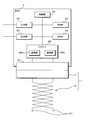
- FIG. 1 is a schematic diagram illustrating an overall configuration of a communication system according to the first embodiment.
- the communication system includes a plurality of communication harnesses 1 and a plurality of ECUs 2 corresponding to communication devices.
- a communication harness 1 serving as a plurality of branch lines is branched from a communication harness 1 serving as a single trunk line, and an ECU 2 is connected to an end of the communication harness 1 serving as a branch line.
- the communication harness 1 includes a connector 11 and a twisted pair wire 12 which will be described later, and the connector 11 is connected to the ECU 2 by being connected to a connector 27 (see FIG. 2) of the ECU 2. That is, the connector 11 is a plug, and the connector 27 is a receptacle.
- the twisted pair wire 12 has a pair of electric wires 121 (see FIG. 3) twisted together.
- FIG. 1 a plurality of ECUs 2 are separately shown by being denoted by reference numerals 2a, 2b, and 2c.
- the communication harnesses 1 connected to the ECUs 2a, 2b, and 2c are denoted by reference numerals 1a, 1b, and 1c, respectively, and the communication harness 1 that is a trunk line is denoted by reference numeral 1d, and the branch lines 1a, 1b, and 1c and main line 1d are shown separately.
- the connectors 11 included in the branch lines 1a to 1c are distinguished from each other by being denoted by reference numerals 11a to 11c.
- the number of ECUs 2 connected to the main line 1d is three, but the number may be less than three, or four or more. Also good.
- communication is performed between the ECUs 2 using the trunk line 1d as a common communication line.
- the trunk line 1d As a common communication line.
- a signal is output from the branch line 1b to the branch line 1b by the ECU 2b
- the signal passes from the branch line 1b to the ECU 2a via the trunk line 1d and the branch line 1a.
- a reflected wave is generated due to impedance mismatch at a connection portion between the ECU 2a and the branch line 1a, that is, a connection portion between the connector 11a and the ECU 2a.
- the reflected wave reaches the ECU 2b through the branch line 1a, the trunk line 1d, and the branch line 1b (see the broken arrow in FIG. 1).
- the reflected wave that has reached the ECU 2b is reflected again by impedance mismatch at the connection portion between the ECU 2a and the branch line 1a. In this way, ringing occurs in the communication system due to repeated signal reflection.
- illustration is abbreviate
- the connector 11 has a configuration for reducing the influence of ringing, which will be described later.
- FIG. 2 is a block diagram showing the configuration of the ECU 2.
- the ECU 2 includes a control unit 21, a ROM (Read Only Memory) 22, a RAM (Random Access Memory) 23, an input unit 24, an output unit 25, a driver 26, a connector 27, and the like.
- the control unit 21 is configured using an arithmetic processing unit such as a CPU (Central Processing Unit) or an MPU (Micro Processing Unit), and performs various controls by reading and executing a control program stored in the ROM 22. Processing can be performed.
- arithmetic processing unit such as a CPU (Central Processing Unit) or an MPU (Micro Processing Unit
- the ROM 22 is composed of a nonvolatile memory element such as an EEPROM (Electrically Erasable Programmable ROM) or a flash memory, for example, and a control program executed by the control unit 21 and information necessary for processing performed by the control unit 21. Etc. are stored in advance.
- the RAM 23 is composed of a memory element such as SRAM (Static RAM) or DRAM (Dynamic RAM), for example, and information generated by the processing of the control unit 21 and information transmitted to and received from another ECU 2. Etc. are stored.
- the input unit 24 receives a signal from an input device such as a sensor such as a vehicle speed sensor or a temperature sensor of the vehicle, or various switches for operation arranged inside and outside the vehicle, and performs sampling of the input signal or A / Information obtained by performing processing such as D conversion is given to the control unit 21.
- the output unit 25 is connected to a load such as a motor or a lamp, and outputs a drive signal for driving these loads in response to an instruction from the control unit 21. Note that the ECU 2 does not necessarily include both the input unit 24 and the output unit 25, and may be configured to include only one of them.
- the driver 26 transmits / receives information according to the CAN protocol to / from another ECU 2 and is connected to the communication harness 1 via the connector 27.
- the driver 26 converts the transmission information given from the control unit 21 into transmission data (frame) according to the CAN protocol, and gives the data to the transmission unit 26a.
- the transmission unit 26a of the driver 26 outputs a signal to the connected communication harness 1 according to the value of each bit of the given transmission data (0 (dominant) or 1 (recessive)).
- the transmitter 26 a outputs a differential signal to the communication harness 1 connected via the connector 27.
- the transmitting unit 26a When transmitting the dominant signal, the transmitting unit 26a outputs a differential signal in which the potential difference between the twisted pair wires 12 included in the communication harness 1 is 2V, and when transmitting the recessive signal, the potential difference is 0V. A differential signal is output.
- the receiving unit 26b receives the differential signal transmitted from the other ECU 2, and gives the received data obtained by the reception to the control unit 21.
- the driver 26 corresponds to a communication unit.
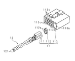
- FIG. 3 is an exploded perspective view schematically showing the configuration of the communication harness 1
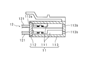
- FIG. 4 is a cross-sectional view schematically showing the configuration of the communication harness 1.
- the communication harness 1 includes the connector 11 and the twisted pair wire 12 as described above.
- the twisted pair wire 12 is formed by twisting a pair of electric wires 121 each covered with a synthetic resin or the like.
- the connector 11 includes two terminals 111, a contact member 112, and a housing 113.
- Each of the terminals 111 is, for example, a female terminal, and is connected to one end portion of the electric wire 121 of the twisted pair wire 12 by crimping, pressure welding, or the like.
- the terminal 111 may be a male terminal.
- the contact member 112 is, for example, an oval plate having two through holes 112a on one surface, and is a rubber member mixed with carbon black.
- the rubber various rubber materials such as silicone rubber, chloroprene rubber (CR rubber), or fluorine rubber can be used.
- the housing 113 has a box shape in which a first opening 113a and a plurality of second openings 113c are arranged in parallel on one surface.
- the second opening 113c has a rectangular shape, and is formed in a matrix on the one surface of the housing 113.
- the first opening 113a has a shape corresponding to the shape of the contact member 112, and has an elliptical shape in the first embodiment.
- two through holes 113b connected to the first opening 113a are formed on the other surface of the housing 113.
- the through holes 113b are formed so as to be continuous with the through holes 112a when the contact member 112 is fitted into the first opening 113a.
- a plurality of holes (not shown) that are continuous with the second openings 113c are provided.
- the user When assembling the communication harness 1 including the above-described constituent members, the user connects the terminals 111 to the respective electric wires 121 by crimping, pressing, or the like, and connects each of the terminals 111 connected to the electric wires 121 to the through holes of the contact member 112. Fit into 112a.
- the contact member 112 since the contact member 112 has elasticity, the terminal 111 can be inserted by expanding the through hole 112a.
- the user twists the two electric wires 121 into the twisted pair wire 12 in a state where the contact member 112 into which the terminal 111 is fitted is fixed.
- the user inserts the contact member 112 into the first opening 113a of the housing 113 so that the through-hole 112a is continuous with the through-hole 113b, so that the terminal 111 and the contact member 112 are accommodated in the housing 113.
- Assemble harness 1. As described above, the electric wire 121 is connected to the terminal 111, and the electric wire 121 is twisted in a state where the connected terminal 111 is fitted in the contact member 112, whereby the two electric wires 121 are not twisted. The length can be shortened and the noise resistance can be improved. Note that the order of assembling the communication harness 1 described above is an example.
- the communication harness 1 is connected to the terminals 111, and after the terminals 111 are fitted into the contact members 112, the contact members 112 are encased. It may be fitted into the body 113, and its assembly order is not limited. Further, another communication line used for communication may be appropriately inserted into the second opening 113c.
- the communication harness 1 configured as described above is connected to the ECU 2 by fitting the connector 27 of the ECU 2 from the other surface side of the housing 113.
- a differential signal including ringing is input to the connected ECU 2
- a voltage representing the differential signal is applied to each electric wire 121 of the twisted pair wire 12 of the communication harness 1 and the terminal 111 of the connector 11.
- the terminal 111 is fitted in the through hole 112 a of the contact member 112, the terminal 111 is in contact with the contact member 112. Therefore, a voltage representing the differential signal is also applied to the contact member 112.
- FIG. 5 is a circuit diagram schematically showing an equivalent circuit of the contact member 112
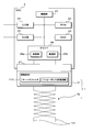
- FIG. 6 is a block diagram illustrating the function of the contact member 112.
- the resistance in FIG. 5 corresponds to carbon black
- the capacitor corresponds to rubber.
- the contact member 112 has a plurality of capacitors and resistors connected in series and in parallel. Therefore, when a voltage is applied to the contact member 112, it can function as a low-pass filter including a resistor and a capacitor.
- the contact member 112 functioning as a low-pass filter can remove ringing as a high frequency component as described above.
- the input impedance of the communication device including the ECU 2 is very high as compared with the characteristic impedance of the twisted pair wire 12. Therefore, the contact member 112 that contacts the twisted pair wire 12 and the terminal 111 connected to the ECU 2 can function as an impedance conversion circuit including a resistor and a capacitor.
- the contact member 112 functioning as an impedance conversion circuit can reduce the degree of mismatch between the characteristic impedance of the electric wire 121 and the input impedance of the ECU 2, and can reduce the influence of ringing.
- the contact member 112 that functions as a low-pass filter and an impedance conversion circuit can be provided in the connector 11, and it is necessary to provide the ECU 2 with a passive element that reduces the influence of ringing. Therefore, the ECU 2 connected to the communication harness 1 can be downsized. Furthermore, since the contact member 112 is accommodated in the housing 113 of the connector 11, the connector 11 can prevent an increase in size while reducing the influence of ringing.
- the contact member 112 is not particularly limited, but preferably has a volume resistivity in the range of 1 to 30 ⁇ ⁇ cm and a relative dielectric constant in the range of 2 to 9.
- volume resistivity in the range of 1 to 30 ⁇ ⁇ cm
- dielectric constant in the range of 2 to 9.
- the volume resistivity and relative dielectric constant of the contact member 112 can be appropriately set based on the characteristic impedance of the twisted pair wire 12 to be connected and the input impedance of the communication device. Therefore, the material of the contact member 112 is not limited as described above as long as the material is suitable for the environment of the vehicle. In addition to the environment of the vehicle, a material suitable for the environment to be used may be used. It is. That is, the contact member 112 may be a material having a volume resistivity and a relative dielectric constant according to the characteristic impedance of the twisted pair wire 12 to be connected and the input impedance of the communication device.
- the communication harness 1 configured as described above can reduce the influence of ringing by the contact member 112 functioning as a low-pass filter and an impedance conversion circuit. Moreover, since the contact member 112 is accommodated in the housing 113 of the connector 11 as described above, the ECU 2 can be reduced in size and the connector 11 can be prevented from being increased in size.
- the user when the user assembles the communication harness 1, the user only has to fit the terminal 111 to which the twisted pair wire 12 is connected into the through hole 112 a of the contact member 112. Therefore, the convenience in assembling the communication harness 1 is improved.
- the user when the user assembles the communication harness 1, the user only has to fit the contact member 112 from the first opening 113 a of the housing 113. Therefore, the convenience in assembling the communication harness 1 is improved.
- the contact member 112 is equivalent to a circuit in which a resistor and a capacitor are connected in series and in parallel as described above.
- the communication harness 1 is an open end. Therefore, the communication harness 1 can reduce the influence of the ringing of the entire communication system by providing the connector 11 having the contact member 112 even when the ECU 2 is not connected.
- the connector 11 is provided in any one place in the communication system, it is effective.
- the influence of ringing that occurs between the twisted pair wire 12 and the ECU 2 increases according to the length of the twisted pair wire 12. Therefore, it is preferable to be provided at the end of the twisted pair wire 12 provided in the communication system as a long branch line.
- the housing 113 of the connector 11 only needs to be formed with the first opening 113a and the two through holes 113b, and it does not matter whether the second opening 113c is formed or not. Further, a plurality of sets of first openings 113a and two through holes 113b may be provided on both sides of the housing 113, and a plurality of sets of twisted pair wires 12 and contact members 112 may be fitted into the first openings 113a, respectively.
- FIG. 7 is a cross-sectional view schematically showing the configuration of the connector 27 of the ECU 2 in the second embodiment.
- the connector 27 includes two terminals 271, a contact member 272, and a housing 273.
- the housing 273 has a box shape having an opening 273a on one surface and a through hole 273b on the other surface, and has the same shape as the housing 113 of the connector 11 of the first embodiment.
- the contact member 272 is a member made of the same material and shape as in the first embodiment.
- the contact member 272 is fitted into the opening 273a from the formation surface side of the through hole 272a so that the through hole 272a is continuous with the through hole 273b of the housing 273.
- the terminal 271 is, for example, a male terminal having an L-shaped bent shape.
- the terminal 271 is inserted into the through holes 273b and 272a, and one side including the bent portion protrudes outside the housing 273 and the other side is accommodated in the housing 273. .
- the two terminals 271 only need to be inserted so that at least part of the terminals 271 contacts the contact member 272.
- one end of the terminal 271 is connected to a circuit board constituting the driver 26 and the like of the ECU 2.
- the connector 27 is connected to the communication harness 1 by fitting the connector 11 into the opening 273 a of the housing 273 and connecting the other end of the terminal 271 to the terminal 111 of the connector 11 of the communication harness 1. Even in this case, the same effect as that of the first embodiment can be obtained. That is, the influence of ringing can be reduced and the ECU 2 can be downsized.
- the connector 27 may be configured so that a plurality of connectors 11 can be fitted.
- the connector 27 may include a plurality of sets of two terminals 271, and a plurality of sets of two through holes 273 b may be formed in the housing 273 so that each set of terminals 271 can be inserted.
- the influence of ringing caused by each communication harness including the fitted connector 11 can be reduced by fitting the contact members 272 at the corresponding positions so as not to contact each other.
- terminal 271 in the second embodiment has been described as having an L-shaped bent shape, the shape is not limited as long as it is a male terminal inserted through the through holes 273b and 273a.
- the contact holes 112a and 272a are formed in the contact members 112 and 272 of the first and second embodiments, respectively, the shape is not limited as long as it can contact the terminals 111 and 271. That is, the contact members 112 and 272 do not have to be plate-shaped such as an elliptical plate, and the through holes 112a and 272a do not have to be formed.
Landscapes
- Details Of Connecting Devices For Male And Female Coupling (AREA)
Abstract
リンギングの影響を低減することができ、かつ接続される通信装置の小型化を実現することができる通信ハーネス、当該通信ハーネスを備える通信システム、及び当該通信ハーネスの接続に用いられるコネクタを提供する。 一対の電線121が撚り合わされたツイストペア線12と、該ツイストペア線12の電線121夫々の一端に接続される2つの端子11及び該2つの端子11を収容する筐体113を有するコネクタ11とを備える通信ハーネスは、誘電性を有する材料及び導電性を有する材料を含み、前記2つの端子111に接触して前記筐体113内に収容される接触部材112を備える。
Description
本願は、ツイストペア線及びコネクタを備える通信ハーネス、該通信ハーネスを備える通信システム、及び該通信ハーネスの接続に用いられるコネクタに関する。
従来、複数の通信ハーネスが接続された車載ネットワークを介して複数の通信装置が相互に通信を行う車載通信システムが車両に構築されている。当該車載通信システムにおいて、通信ハーネス間の接続箇所、通信ハーネス及び通信装置間の接続箇所等では、インピーダンスの不整合が生じ易い。インピーダンスの不整合が生じた場合、通信装置が信号を送信するときにリンギングが発生する。発生したリンギングの影響が大きくなった場合、通信装置間の通信に障害が発生する虞がある。そのため、リンギングの影響を低減する方法が提案されている(例えば、特許文献1参照)。特許文献1に記載のデータ通信システムは、通信装置(ノード)内の通信ハーネス(伝送線路)との接続箇所にフェライトビーズを設けており、当該フェライトビーズが高周波成分を除去することによって、リンギングの影響を低減する。
近年、車両制御の複雑化に伴って通信装置の数が増加しており、多数の通信装置の配設場所を確保するために、通信装置の小型化が望まれている。しかしながら、特許文献1に記載の通信システムにおいては、通信装置内にフェライトビーズが設けられており、リンギングの影響を低減することができるものの、通信装置の小型化について考慮されていない。
本願の目的は、リンギングの影響を低減することができ、かつ接続される通信装置の小型化を実現することができる通信ハーネス、当該通信ハーネスを備える通信システム、及び当該通信ハーネスの接続に用いられるコネクタを提供することにある。
本発明の一態様に係る通信ハーネスは、一対の電線が撚り合わされたツイストペア線と、該電線夫々の一端に接続される2つの端子及び該2つの端子を収容する筐体を有するコネクタとを備える通信ハーネスであって、誘電性を有する材料及び導電性を有する材料を含み、前記2つの端子に接触して前記筐体内に収容される接触部材を備える。
本発明の一態様に係る通信システムは、上述の通信ハーネスと、該通信ハーネスのコネクタに接続され、該コネクタに接続されたツイストペア線を介して差動信号を入出力する通信装置とを備える。
本発明の一態様に係るコネクタは、2つの端子と、該2つの端子を収容する筐体とを備え、一対の電線が撚り合わされたツイストペア線及び該ツイストペア線を介して差動信号を入出力する通信部間を前記2つの端子を介して接続可能なコネクタであって、誘電性を有する材料及び導電性を有する材料を含み、前記2つの端子に接触して前記筐体内に収容される接触部材を備える。
上記によれば、リンギングの影響を低減することができ、かつ通信装置の小型化を実現することができる通信ハーネス、当該通信ハーネスを備える通信システム、及び当該通信ハーネスの接続に用いられるコネクタを提供することを可能とする。
[本発明の実施形態の説明]
最初に本発明の実施態様を列記して説明する。また、以下に記載する実施形態の少なくとも一部を任意に組み合わせてもよい。
最初に本発明の実施態様を列記して説明する。また、以下に記載する実施形態の少なくとも一部を任意に組み合わせてもよい。
(1)本発明の一態様に係る通信ハーネスは、一対の電線が撚り合わされたツイストペア線と、該電線夫々の一端に接続される2つの端子及び該2つの端子を収容する筐体を有するコネクタとを備える通信ハーネスであって、誘電性を有する材料及び導電性を有する材料を含み、前記2つの端子に接触して前記筐体内に収容される接触部材を備える。
本願にあっては、ツイストペア線の電線夫々の一端に接続される2つの端子に接触して筐体内に収容される接触部材を備える。接触部材は、誘電性を有する材料及び導電性を有する材料を含んで構成されている。誘電性を有する材料と導電性を有する材料とが電気的に接続することにより、接触部材は例えばローパスフィルタとして機能することができる。そのため、接触部材はリンギングを高周波成分として除去することができ、リンギングの影響を低減することができる。また、誘電性を有する材料と導電性を有する材料とが電気的に接続することにより、接触部材は例えば接続端子間に介装されたインピーダンス変換回路として機能することができる。一般的に通信ハーネスに接続される通信装置の入力インピーダンスは非常に高いため、接触部材はツイストペア線の電線における特性インピーダンスと、当該入力インピーダンスとの不整合の度合いを低減することができ、リンギングの影響を低減することができる。更に、通信ハーネスに接続される通信装置内にリンギングの影響を低減する受動素子を設ける必要がないため、通信装置の小型化を実現することができる。
(2)前記接触部材は、カーボンブラックが混合されたゴム製である構成が好ましい。
本願にあっては、接触部材はカーボンブラックが混合されたゴム製である。接触部材はカーボンブラックが抵抗として機能し、ゴムが誘電体として機能する。従って、接続部材は例えばローパスフィルタとして機能することができ、リンギングを高周波成分として除去することができる。また、接触部材は例えば接続端子間に介装されたインピーダンス変換回路として機能することができる。一般的に通信ハーネスに接続される通信装置の入力インピーダンスは非常に高いため、ツイストペア線の電線における特性インピーダンスと、当該入力インピーダンスとの不整合の度合いを低減することができ、リンギングの影響を低減することができる。
(3)前記接触部材は、シリコーンゴム、クロロプレンゴム、又はフッ素ゴムにカーボンブラックが混合されている構成が好ましい。
本願にあっては、接触部材はシリコーンゴム、クロロプレンゴム、又はフッ素ゴムにカーボンブラックが混合されている。なお、接触部材の材料は、車両の環境に適合する材料であれば、これらに限定されるものではない。また、接触部材の材料は、車両の環境の他、使用される環境に適合する材料を用いることが可能である。
(4)前記接触部材は一面に2つの貫通孔を有する板状をなし、前記2つの端子は前記2つの貫通孔に各別に嵌め込まれている構成が好ましい。
本願にあっては、接触部材の形状は一面に2つの貫通孔を有する板状である。また、2つの端子は当該2つの貫通孔に各別に嵌め込まれている。従って、使用者が通信ハーネスを組み立てる際に、電線が接続された2つの端子を接触部材の貫通孔に同時に嵌め込むだけでよい。そのため、通信ハーネスの組み立てに際しての利便性が向上する。
(5)前記筐体は一面に開口を有する箱状をなし、前記接触部材は前記貫通孔の形成面側から前記開口に嵌め込まれている構成が好ましい。
本願にあっては、筐体の形状は一面に開口を有する箱状である。また、接触部材は、貫通孔の形成面側から筐体の開口に嵌め込まれている。従って、通信ハーネスを組み立てる際に、接触部材を筐体の開口から嵌め込むだけでよい。そのため、通信ハーネスの組み立てに際しての利便性が向上する。
(6)本発明の一態様に係る通信システムは、上述の通信ハーネスと、該通信ハーネスのコネクタに接続され、該コネクタに接続されたツイストペア線を介して差動信号を入出力する通信装置とを備える。
本願にあっては、上述の通信ハーネスと、通信装置とを備える。通信装置は、当該通信ハーネスのコネクタに接続され、当該コネクタに接続されたツイストペア線を介して差動信号を入出力する。従って、通信ハーネスは、接触部材によってリンギングを高周波成分として除去することができるため、リンギングの影響を低減することができる。また、通信ハーネスは、ツイストペア線の電線における特性インピーダンスと、通信ハーネスに接続される通信装置の入力インピーダンスとの不整合の度合いを接触部材によって低減することができるため、リンギングの影響を低減することができる。更に、通信ハーネスに接続される通信装置内にリンギングの影響を低減する受動素子を設ける必要がないため、通信装置の小型化を実現することができる。
(7)本発明の一態様に係るコネクタは、2つの端子と、該2つの端子を収容する筐体とを備え、一対の電線が撚り合わされたツイストペア線及び該ツイストペア線を介して差動信号を入出力する通信部間を前記2つの端子を介して接続可能なコネクタであって、誘電性を有する材料及び導電性を有する材料を含み、前記2つの端子に接触して前記筐体内に収容される接触部材を備える。
本願にあっては、2つの端子に接触して筐体内に収容される接触部材を備える。接触部材は、誘電性を有する材料及び導電性を有する材料を含んで構成されている。従って、誘電性を有する材料と導電性を有する材料とが電気的に接続することにより、接触部材は例えばローパスフィルタとして機能することができる。そのため、コネクタは、ツイストペア線及び通信部が2つの端子を介して接続された場合に、リンギングを高周波成分として接触部材によって除去することができ、リンギングの影響を低減することができる。また、コネクタは、ツイストペア線及び通信部が2つの端子を介して接続された場合に、電線における特性インピーダンスと、通信ハーネスに接続される通信装置の入力インピーダンスとの不整合の度合いを接触部材によって低減することができるため、リンギングの影響を低減することができる。更に、コネクタに接続される通信装置内にリンギングの影響を低減する受動素子を設ける必要がないため、通信装置の小型化を実現することができる。
(8)前記筐体は、一面に開口を有し、他面に2つの貫通孔を有する箱状をなし、前記接触部材は、一面に2つの貫通孔を有する板状をなし、該一面側から前記開口に嵌め込まれており、前記2つの端子は、メス端子であり、前記接触部材の貫通孔に各別に嵌め込まれている構成が好ましい。
本願にあっては、筐体は一面に開口を有し、他面に2つの貫通孔を有する箱状をなし、前記接触部材は、一面に2つの貫通孔を有する板状をなし、当該一面側から開口に嵌め込まれている。2つの端子は、メス端子であり、接触部材の貫通孔に各別に嵌め込まれている。
(9)前記筐体は、一面に開口を有し、他面に2つの貫通孔を有する箱状をなし、前記接触部材は、一面に2つの貫通孔を有する板状をなし、該一面側から前記開口に嵌め込まれており、前記2つの端子は、オス端子であり、前記筐体及び前記接触部材の貫通孔に各別に挿通されている構成が好ましい。
本願にあっては、筐体は一面に開口を有し、他面に2つの貫通孔を有する箱状をなし、前記接触部材は、一面に2つの貫通孔を有する板状をなし、該一面側から開口に嵌め込まれている。2つの端子は、オス端子であり、筐体及び接触部材の貫通孔に各別に挿通されている。
[本発明の実施形態の詳細]
本発明の実施形態に係る通信システムの具体例を、以下に図面に参照しつつ説明する。なお、本発明はこれらの例示に限定されるものではなく、請求の範囲によって示され、請求の範囲と均等の意味及び範囲内での全ての変更が含まれることが意図される。
本発明の実施形態に係る通信システムの具体例を、以下に図面に参照しつつ説明する。なお、本発明はこれらの例示に限定されるものではなく、請求の範囲によって示され、請求の範囲と均等の意味及び範囲内での全ての変更が含まれることが意図される。
(実施形態1)
図1は、実施形態1に係る通信システムの全体の構成を示す模式図である。通信システムは、複数の通信ハーネス1と通信装置に相当する複数のECU2とを備える。通信システムにおいては、1本の幹線となる通信ハーネス1から複数の支線となる通信ハーネス1が分岐接続しており、支線となる通信ハーネス1の端部にECU2が接続されている。通信ハーネス1は、後述のコネクタ11とツイストペア線12とで構成されており、コネクタ11がECU2のコネクタ27(図2参照)に接続されることによってECU2と接続している。つまり、コネクタ11はプラグであり、コネクタ27はレセプタクルである。ツイストペア線12は、一対の電線121(図3参照)が撚り合わされている。
図1は、実施形態1に係る通信システムの全体の構成を示す模式図である。通信システムは、複数の通信ハーネス1と通信装置に相当する複数のECU2とを備える。通信システムにおいては、1本の幹線となる通信ハーネス1から複数の支線となる通信ハーネス1が分岐接続しており、支線となる通信ハーネス1の端部にECU2が接続されている。通信ハーネス1は、後述のコネクタ11とツイストペア線12とで構成されており、コネクタ11がECU2のコネクタ27(図2参照)に接続されることによってECU2と接続している。つまり、コネクタ11はプラグであり、コネクタ27はレセプタクルである。ツイストペア線12は、一対の電線121(図3参照)が撚り合わされている。
なお、図1中においては、複数のECU2夫々を2a、2b、及び2cの符号を付して区別して示している。また、ECU2a、2b、及び2cに接続されている通信ハーネス1夫々を1a、1b、及び1cの符号を付し、幹線となる通信ハーネス1に1dの符号を付して支線1a、1b、及び1c並びに幹線1d夫々を区別して示している。また、支線1a~1c夫々が有するコネクタ11を11a~11cの符号を付して区別し、各支線1a、1b、及び1cのツイストペア線12を12a~12cの符号を付して区別する。更に、図1中においては、幹線1dに接続されているECU2の数が3つであることを示しているが、3つ未満の数であってもよいし、4つ以上の数であってもよい。
このように構成された通信システムにおいては、ECU2間で幹線1dを共通の通信線として通信が行われる。例えば、ECU2bにて支線1bへ信号が出力された場合、この信号は支線1bから幹線1d、支線1aを経てECU2aへ至る。このとき、ECU2aと支線1aとの接続部分、即ちコネクタ11aとECU2aとの接続部分においてインピーダンスの不整合により反射波が生じる。反射波は、支線1a、幹線1d、及び支線1bを経てECU2bに至る(図1中の破線の矢印参照)。ECU2bに至った反射波は、再度ECU2aと支線1aとの接続部分においてインピーダンスの不整合により反射される。このように信号の反射が繰り返されることによって通信システムにおいてリンギングが生じる。また、図1において図示は省略するが、ECU2cにおいても同様の反射波が生ずる。更に、幹線1dと各支線1a~1cとの分岐部分においても反射波が生ずる場合がある。
実施形態1においては、コネクタ11がリンギングの影響を低減するための構成を有し、当該構成については後述する。
実施形態1においては、コネクタ11がリンギングの影響を低減するための構成を有し、当該構成については後述する。
次に、ECU2の構成について説明する。図2は、ECU2の構成を示すブロック図である。ECU2は、制御部21、ROM(Read Only Memory)22、RAM(Random Access Memory)23、入力部24、出力部25、ドライバ26、及びコネクタ27等を備えて構成されている。制御部21は、CPU(Central Processing Unit)又はMPU(Micro Processing Unit)等の演算処理装置を用いて構成されるものであり、ROM22に記憶された制御プログラムを読み出して実行することにより種々の制御処理を行うことができる。
ROM22は、例えばEEPROM(Electrically Erasable Programmable ROM)又はフラッシュメモリ等の不揮発性のメモリ素子で構成されるものであり、制御部21にて実行される制御プログラム及び制御部21が行う処理に必要な情報等が予め記憶されている。RAM23は、例えばSRAM(Static RAM)又はDRAM(Dynamic RAM)等のメモリ素子で構成されるものであり、制御部21の処理に伴って生成された情報及び他のECU2との間で送受信する情報等の種々の情報が記憶される。
入力部24は、例えば車両の車速センサ若しくは温度センサ等のセンサ、又は、車両の内外に配置された操作用の種々のスイッチ等の入力装置からの信号が入力され、入力信号のサンプリング又はA/D変換等の処理を行って得られた情報を制御部21へ与える。出力部25は、例えばモータ又はランプ等の負荷が接続され、制御部21からの指示に応じてこれらの負荷を駆動する駆動信号を出力する。なお、ECU2は必ずしも入力部24及び出力部25の両方を備える必要はなく、何れか一方のみを備える構成であってよい。
ドライバ26は、他のECU2との間でCANプロトコルに従った情報の送受信を行うものであり、コネクタ27を介して通信ハーネス1と接続している。ドライバ26は、制御部21から与えられた送信情報をCANプロトコルに応じた送信用のデータ(フレーム)に変換して送信部26aへ与える。ドライバ26の送信部26aは、与えられた送信データの各ビットの値(0(ドミナント)又は1(レセシブ))に応じて、接続してある通信ハーネス1に信号を出力する。送信部26aはコネクタ27を介して接続する通信ハーネス1に差動信号を出力する。送信部26aは、ドミナントの信号を送信するときは、通信ハーネス1に含まれるツイストペア線12間の電位差が2Vとなる差動信号を出力し、レセシブの信号を送信するときは、当該電位差が0Vとなる差動信号を出力する。受信部26bは、他のECU2から送信された差動信号を受信し、受信して得た受信データを制御部21に与える。ドライバ26は通信部に相当する。
次に、通信ハーネス1の構成について説明する。図3は通信ハーネス1の構成を模式的に示す分解斜視図であり、図4は通信ハーネス1の構成を模式的に示す断面図である。通信ハーネス1は、上述のようにコネクタ11とツイストペア線12とを備える。ツイストペア線12は例えば、合成樹脂等で各被覆された一対の電線121が撚り合わされてなる。コネクタ11は、2つの端子111、接触部材112、及び筐体113を有する。端子111は夫々、例えばメス端子であり、ツイストペア線12の電線121の一端部に圧着、圧接等により接続されている。なお、端子111はオス端子であってもよい。
接触部材112は例えば、一面に2つの貫通孔112aを有する楕円板状をなし、カーボンブラックが混合されたゴム製の部材である。当該ゴムは、例えばシリコーンゴム、クロロプレンゴム(CRゴム)、又はフッ素ゴム等の各種のゴム材を用いることができる。
筐体113は、一面に第1開口113aと、複数の第2開口113cとが並設された箱状をなす。第2開口113cは矩形をなし、筐体113の当該一面にマトリクス状に形成されている。第1開口113aは、接触部材112の形状に対応する形状をなし、実施形態1においては楕円形をなす。また、筐体113の他面には、第1開口113aに連なる2つの貫通孔113bが形成されている。貫通孔113bは夫々、接触部材112が第1開口113aに嵌め込まれたときに貫通孔112aと連なるように形成されている。更に、筐体113の他面には、第2開口113c夫々に連なる複数の孔(図示略)が設けられている。
以上に示した構成部材を備える通信ハーネス1の組み立てるに際して、使用者は、電線121夫々に端子111を圧着、圧接等により接続し、電線121を接続した端子111夫々を、接触部材112の貫通孔112aに嵌め込む。なお、接触部材112は弾性を有するため、貫通孔112aを拡げて、端子111を挿通させることができる。次いで、使用者は、端子111を嵌め込んだ接触部材112を固定した状態で、2本の電線121を撚り合わせてツイストペア線12とする。その後、使用者は、貫通孔112aが貫通孔113bに連なるように接触部材112を筐体113の第1開口113aに嵌め込むことにより、端子111、接触部材112を筐体113に収容し、通信ハーネス1を組み上げる。このように、電線121が端子111に接続され、接続された端子111が接触部材112に嵌め込まれた状態で当該電線121を撚り合わせられることにより、2本の電線121が撚られていない部分の長さを短くすることができ、ノイズ耐性を良好とすることができる。なお、以上の通信ハーネス1の組立順序は一例であり、ツイストペア線12が予め形成された状態で、端子111に接続され、各端子111が接触部材112に嵌め込まれた後に、接触部材112が筐体113に嵌め込まれてもよく、その組立順序は問わない。また、第2開口113cに通信に用いる他の通信線が適宜挿入されていてもよい。
以上のように構成された通信ハーネス1は、筐体113の他面側からECU2のコネクタ27が嵌合されることによってECU2と接続する。接続されたECU2にリンギングを含む差動信号が入力されるとき、通信ハーネス1のツイストペア線12の各電線121及びコネクタ11の端子111に当該差動信号を表す電圧が印加される。このとき、端子111は接触部材112の貫通孔112aに嵌め込まれているため、当該接触部材112と接触している。従って、接触部材112に対しても当該差動信号を表す電圧が印加される。
次に、接触部材112に電圧が印加されたときの作用について説明する。接触部材112を構成するカーボンブラックは導電性を有する材料に相当し、ゴムは誘電性を有する材料に相当し、接触部材112には導電性及び誘電性双方の電気的特性を有する。図5は、接触部材112の等価回路を略示する回路図であり、図6は、接触部材112の機能を説明するブロック図である。図5中の抵抗はカーボンブラックに相当し、コンデンサはゴムに相当する。図5に示すように、接触部材112は複数のコンデンサ及び抵抗が、直列及び並列に接続している。そのため、接触部材112に電圧が印加された場合、抵抗及びコンデンサを含むローパスフィルタとして機能することができる。ローパスフィルタとして機能する接触部材112は、上述のようにリンギングを高周波成分として除去することができる。
また、一般的に、ECU2を含む通信装置の入力インピーダンスは、ツイストペア線12の特性インピーダンスに比べて非常に高い。従って、ツイストペア線12及びECU2に接続された端子111に接触する接触部材112は、抵抗及びコンデンサを含むインピーダンス変換回路として機能することができる。インピーダンス変換回路として機能する接触部材112は、電線121の特性インピーダンスと、ECU2の入力インピーダンスとの不整合の度合いを低減することができ、リンギングの影響を低減することができる。
更に、図6に示すように、ローパスフィルタ及びインピーダンス変換回路として機能する接触部材112が、コネクタ11内に設けられた構成とすることができ、ECU2にリンギングの影響を低減させる受動素子を設ける必要がないため、通信ハーネス1に接続されるECU2の小型化を実現することができる。更に、接触部材112はコネクタ11の筐体113内に収容されているため、コネクタ11はリンギングの影響を低減しつつ、大型化を防止することができる。
また、接触部材112は特に限定を意図しないが、体積抵抗率が1~30Ω・cmの範囲内にあり、比誘電率が2~9の範囲内にあることが好ましい。体積抵抗率の値が大きすぎる又は小さすぎる場合、例えば、電線121の特性インピーダンスとECU2の入力インピーダンスとの不整合の度合いを低減する性能が低下する虞がある。また、比誘電率の値が小さすぎる場合、例えば、ローパスフィルタとしての効果が小さくなる。更に、比誘電率の値が大きすぎる場合、例えば、ECU2からの差動信号の波形の立下り又は立上がり時間が増加し、通信が遅延し所定時間に送信先に差動信号が届かない虞がある。なお、接触部材112の体積抵抗率及び比誘電率は、接続されるツイストペア線12の特性インピーダンス及び通信装置の入力インピーダンスに基づいて、適宜設定され得る。従って、接触部材112の材料は、車両の環境に適合する材料であれば、上述のように限定されるものではなく、車両の環境の他、使用される環境に適合する材料を用いることも可能である。即ち、接触部材112は、接続されるツイストペア線12の特性インピーダンス及び通信装置の入力インピーダンス応じた体積抵抗率及び比誘電率を有する材料であればよい。
以上のように構成された通信ハーネス1は、接触部材112がローパスフィルタ及びインピーダンス変換回路として機能することにより、リンギングの影響を低減することができる。また、上述のように接触部材112がコネクタ11の筐体113内に収容されているため、ECU2の小型化と、コネクタ11の大型化の防止とを実現することができる。
また、使用者は通信ハーネス1を組み立てる際に、ツイストペア線12が接続された端子111を接触部材112の貫通孔112aに嵌め込むだけでよい。そのため、通信ハーネス1の組み立てに際しての利便性が向上する。
また、使用者は、通信ハーネス1を組み立てる際に、接触部材112を筐体113の第1開口113aから嵌め込むだけでよい。そのため、通信ハーネス1の組み立てに際しての利便性が向上する。
更に、接触部材112は上述のように抵抗及びコンデンサが直列及び並列に接続している回路と等価である。図1に示したような通信システムにおいて、通信ハーネス1にECU2が接続されていない場合に、コネクタ11が設けられていない場合には、通信ハーネス1が開放端となる。従って、通信ハーネス1は、ECU2が接続されていない場合であっても接触部材112を有するコネクタ11が設けられていることによって、通信システム全体のリンギングの影響を低減することができる。
なお、コネクタ11は、通信システムの中の何れか1箇所に設けられていても効果がある。ツイストペア線12とECU2との間で生じるリンギングの影響は、ツイストペア線12の長さに応じて大きくなる。そのため、長さの長い支線として通信システムに設けられているツイストペア線12の端部に設けられることが好ましい。
また、コネクタ11の筐体113は、第1開口113a及び2つの貫通孔113bが形成されていればよく、第2開口113cの形成の有無、外形等は問わない。また、第1開口113a及び2つの貫通孔113bが筐体113の両面夫々に複数組並設され、複数組のツイストペア線12及び接触部材112が夫々第1開口113aに嵌め込まれていてもよい。
(実施形態2)
実施形態1においては、通信ハーネス1のコネクタ11内に端子111に接触する接触部材112を収容することを説明した。実施形態2においては、ECU2のコネクタ27、つまりレセプタクルに実施形態1のコネクタ11と同様の構成を有する例について説明する。なお、以下で説明する構成及び作用を除くその他の構成及び作用は上述の実施形態1と同様であるため、同様の構成に関する詳細な説明及びその作用効果の説明は簡潔のため省略する。
実施形態1においては、通信ハーネス1のコネクタ11内に端子111に接触する接触部材112を収容することを説明した。実施形態2においては、ECU2のコネクタ27、つまりレセプタクルに実施形態1のコネクタ11と同様の構成を有する例について説明する。なお、以下で説明する構成及び作用を除くその他の構成及び作用は上述の実施形態1と同様であるため、同様の構成に関する詳細な説明及びその作用効果の説明は簡潔のため省略する。
図7は、実施形態2におけるECU2のコネクタ27の構成を模式的に示す断面図である。コネクタ27は、2つの端子271、接触部材272、及び筐体273を備える。筐体273は、一面に開口273a、他面に貫通孔273bを有する箱状をなし、実施形態1のコネクタ11の筐体113と同様の形状をなす。接触部材272は、実施形態1と同様の材質及び形状からなる部材である。接触部材272は、貫通孔272aが筐体273の貫通孔273bに連なるように、貫通孔272aの形成面側から開口273aに嵌め込まれている。端子271は例えば、L字形の屈曲形状をなすオス端子であり、貫通孔273b及び272aに挿通され、屈曲部分を含む一側が筐体273外に突出し、他側が筐体273内に収容されている。なお、2つの端子271は、少なくとも一部が接触部材272に接触するように挿通されていればよい。
以上のように構成されたコネクタ27は、端子271の一端がECU2のドライバ26等を構成する回路基板に接続される。また、コネクタ27は、筐体273の開口273aにコネクタ11が嵌合され、端子271の他端が通信ハーネス1のコネクタ11の端子111に接続されることで通信ハーネス1と接続する。このように構成された場合であっても、実施形態1と同様の効果を得ることができる。即ち、リンギングの影響を低減することができ、かつECU2の小型化を実現することができる。なお、コネクタ27は複数のコネクタ11が嵌合可能なように構成されていてもよい。即ち、コネクタ27は2つの端子271を複数組有し、筐体273に、各組の端子271が挿通可能なように、2つの貫通孔273bが複数組形成されていてもよい。この場合にあっては、複数の接触部材272が互いに接触しないように該当位置に嵌め込まれることによって、嵌合されたコネクタ11を備える各通信ハーネスに起因するリンギングの影響を低減することができる。
なお、実施形態2における端子271は、L字形の屈曲形状をなしていることを説明したが、貫通孔273b及び273aに挿通されているオス端子であれば形状は問わない。
なお、実施形態1及び2の接触部材112及び272には夫々、貫通孔112a及び272aが形成されていることを説明したが、端子111及び271に接触できる構成であれば、形状は問わない。即ち、接触部材112及び272は、楕円板等の板状でなくともよいし、貫通孔112a及び272aが形成されていなくともよい。
1 通信ハーネス
2 ECU
11 コネクタ
111 端子
112 接触部材
112a 貫通孔
113 筐体
113a 第1開口
113b 貫通孔
113c 第2開口
12 ツイストペア線
121 電線
21 制御部
22 ROM
23 RAM
24 入力部
25 出力部
26 ドライバ
26a 送信部
26b 受信部
27 コネクタ
271 端子
272 接触部材
273 筐体
2 ECU
11 コネクタ
111 端子
112 接触部材
112a 貫通孔
113 筐体
113a 第1開口
113b 貫通孔
113c 第2開口
12 ツイストペア線
121 電線
21 制御部
22 ROM
23 RAM
24 入力部
25 出力部
26 ドライバ
26a 送信部
26b 受信部
27 コネクタ
271 端子
272 接触部材
273 筐体
Claims (9)
- 一対の電線が撚り合わされたツイストペア線と、該電線夫々の一端に接続される2つの端子及び該2つの端子を収容する筐体を有するコネクタとを備える通信ハーネスであって、
誘電性を有する材料及び導電性を有する材料を含み、前記2つの端子に接触して前記筐体内に収容される接触部材
を備える通信ハーネス。 - 前記接触部材は、カーボンブラックが混合されたゴム製である
請求項1に記載の通信ハーネス。 - 前記接触部材は、シリコーンゴム、クロロプレンゴム、又はフッ素ゴムにカーボンブラックが混合されている
請求項2に記載の通信ハーネス。 - 前記接触部材は一面に2つの貫通孔を有する板状をなし、
前記2つの端子は前記2つの貫通孔に各別に嵌め込まれている
請求項1から3までの何れか一つに記載の通信ハーネス。 - 前記筐体は一面に開口を有する箱状をなし、
前記接触部材は前記貫通孔の形成面側から前記開口に嵌め込まれている
請求項4に記載の通信ハーネス。 - 請求項1から5までの何れか一つに記載の通信ハーネスと、
該通信ハーネスのコネクタに接続され、該コネクタに接続されたツイストペア線を介して差動信号を入出力する通信装置と
を備える通信システム。 - 2つの端子と、該2つの端子を収容する筐体とを備え、一対の電線が撚り合わされたツイストペア線及び該ツイストペア線を介して差動信号を入出力する通信部間を前記2つの端子を介して接続可能なコネクタであって、
誘電性を有する材料及び導電性を有する材料を含み、前記2つの端子に接触して前記筐体内に収容される接触部材
を備えるコネクタ。 - 前記筐体は、一面に開口を有し、他面に2つの貫通孔を有する箱状をなし、
前記接触部材は、一面に2つの貫通孔を有する板状をなし、該一面側から前記開口に嵌め込まれており、
前記2つの端子は、メス端子であり、前記接触部材の貫通孔に各別に嵌め込まれている
請求項7に記載のコネクタ。 - 前記筐体は、一面に開口を有し、他面に2つの貫通孔を有する箱状をなし、
前記接触部材は、一面に2つの貫通孔を有する板状をなし、該一面側から前記開口に嵌め込まれており、
前記2つの端子は、オス端子であり、前記筐体及び前記接触部材の貫通孔に各別に挿通されている
請求項7に記載のコネクタ。
Applications Claiming Priority (2)
| Application Number | Priority Date | Filing Date | Title |
|---|---|---|---|
| JP2015-087656 | 2015-04-22 | ||
| JP2015087656A JP2016207455A (ja) | 2015-04-22 | 2015-04-22 | 通信ハーネス、通信システム、及びコネクタ |
Publications (1)
| Publication Number | Publication Date |
|---|---|
| WO2016170960A1 true WO2016170960A1 (ja) | 2016-10-27 |
Family
ID=57144359
Family Applications (1)
| Application Number | Title | Priority Date | Filing Date |
|---|---|---|---|
| PCT/JP2016/061031 Ceased WO2016170960A1 (ja) | 2015-04-22 | 2016-04-04 | 通信ハーネス、通信システム、及びコネクタ |
Country Status (2)
| Country | Link |
|---|---|
| JP (1) | JP2016207455A (ja) |
| WO (1) | WO2016170960A1 (ja) |
Families Citing this family (1)
| Publication number | Priority date | Publication date | Assignee | Title |
|---|---|---|---|---|
| JP7069758B2 (ja) * | 2018-01-31 | 2022-05-18 | 株式会社Gsユアサ | 蓄電素子 |
Citations (4)
| Publication number | Priority date | Publication date | Assignee | Title |
|---|---|---|---|---|
| JPS62142167U (ja) * | 1986-03-04 | 1987-09-08 | ||
| JP2007036812A (ja) * | 2005-07-28 | 2007-02-08 | Smk Corp | カメラモジュール用コネクタのシールド及び防塵構造 |
| JP2010113925A (ja) * | 2008-11-06 | 2010-05-20 | Autonetworks Technologies Ltd | 伝送波形ノイズ緩和部材 |
| JP2015053633A (ja) * | 2013-09-09 | 2015-03-19 | 株式会社オートネットワーク技術研究所 | 通信システム |
-
2015
- 2015-04-22 JP JP2015087656A patent/JP2016207455A/ja active Pending
-
2016
- 2016-04-04 WO PCT/JP2016/061031 patent/WO2016170960A1/ja not_active Ceased
Patent Citations (4)
| Publication number | Priority date | Publication date | Assignee | Title |
|---|---|---|---|---|
| JPS62142167U (ja) * | 1986-03-04 | 1987-09-08 | ||
| JP2007036812A (ja) * | 2005-07-28 | 2007-02-08 | Smk Corp | カメラモジュール用コネクタのシールド及び防塵構造 |
| JP2010113925A (ja) * | 2008-11-06 | 2010-05-20 | Autonetworks Technologies Ltd | 伝送波形ノイズ緩和部材 |
| JP2015053633A (ja) * | 2013-09-09 | 2015-03-19 | 株式会社オートネットワーク技術研究所 | 通信システム |
Also Published As
| Publication number | Publication date |
|---|---|
| JP2016207455A (ja) | 2016-12-08 |
Similar Documents
| Publication | Publication Date | Title |
|---|---|---|
| KR102294506B1 (ko) | 회전 부하를 저지하는 변형 완화 유닛을 갖는 페어가-감소된 이더넷 응용을 위한 패치 코드 및 관련 변형 완화 유닛 및 커넥터 | |
| US9004951B2 (en) | Multi-functional transfer connector for connecting with different receptacles | |
| US7855573B1 (en) | Controller area network active bus terminator | |
| WO2005038987A3 (en) | Electronic locking differential with bulkhead connector | |
| WO2011105545A1 (ja) | 通信コネクタ、通信ハーネス及び通信システム | |
| US9484672B2 (en) | Adapter for USB and HSD interfaces | |
| CN113169538B (zh) | 接头连接器 | |
| CN105529547A (zh) | 车辆电缆组件 | |
| WO2016170960A1 (ja) | 通信ハーネス、通信システム、及びコネクタ | |
| EP4082083B1 (en) | Signal connector system | |
| JP2015053633A (ja) | 通信システム | |
| CN102693117B (zh) | 接口电路及具有接口电路的电子装置 | |
| CN207052827U (zh) | 一种弯角插接连接器 | |
| CN206049552U (zh) | 终端电阻、汽车用电器盒及汽车 | |
| JP2022141060A (ja) | ガスエンジン駆動式空気調和装置の通信システム | |
| CN111448623B (zh) | 布线系统 | |
| JP6895650B2 (ja) | 通信用ハーネス及び中継コネクタ | |
| JP2005285043A (ja) | センサ用ケーブル | |
| JP2015088919A (ja) | 通信システム及び通信装置 | |
| JP2006246280A (ja) | 分岐ケーブル接続装置及び分岐ケーブル | |
| CN217485776U (zh) | 用于发动机的通讯功能线束总成及发动机电子控制装置 | |
| US9871553B2 (en) | Audio apparatus and audio communication channel circuit | |
| JP2008066157A (ja) | 分岐コネクタ | |
| WO2014084783A1 (en) | Modular connector | |
| JP2016103693A (ja) | 通信システム |
Legal Events
| Date | Code | Title | Description |
|---|---|---|---|
| 121 | Ep: the epo has been informed by wipo that ep was designated in this application |
Ref document number: 16782981 Country of ref document: EP Kind code of ref document: A1 |
|
| NENP | Non-entry into the national phase |
Ref country code: DE |
|
| 122 | Ep: pct application non-entry in european phase |
Ref document number: 16782981 Country of ref document: EP Kind code of ref document: A1 |