WO2016170909A1 - 吸収性物品用の部品を製造する方法及び装置 - Google Patents
吸収性物品用の部品を製造する方法及び装置 Download PDFInfo
- Publication number
- WO2016170909A1 WO2016170909A1 PCT/JP2016/059499 JP2016059499W WO2016170909A1 WO 2016170909 A1 WO2016170909 A1 WO 2016170909A1 JP 2016059499 W JP2016059499 W JP 2016059499W WO 2016170909 A1 WO2016170909 A1 WO 2016170909A1
- Authority
- WO
- WIPO (PCT)
- Prior art keywords
- pushing
- sheet member
- sheet
- pushing member
- folding
- Prior art date
- Legal status (The legal status is an assumption and is not a legal conclusion. Google has not performed a legal analysis and makes no representation as to the accuracy of the status listed.)
- Ceased
Links
Images





Classifications
-
- A—HUMAN NECESSITIES
- A61—MEDICAL OR VETERINARY SCIENCE; HYGIENE
- A61F—FILTERS IMPLANTABLE INTO BLOOD VESSELS; PROSTHESES; DEVICES PROVIDING PATENCY TO, OR PREVENTING COLLAPSING OF, TUBULAR STRUCTURES OF THE BODY, e.g. STENTS; ORTHOPAEDIC, NURSING OR CONTRACEPTIVE DEVICES; FOMENTATION; TREATMENT OR PROTECTION OF EYES OR EARS; BANDAGES, DRESSINGS OR ABSORBENT PADS; FIRST-AID KITS
- A61F13/00—Bandages or dressings; Absorbent pads
- A61F13/15—Absorbent pads, e.g. sanitary towels, swabs or tampons for external or internal application to the body; Supporting or fastening means therefor; Tampon applicators
-
- A—HUMAN NECESSITIES
- A61—MEDICAL OR VETERINARY SCIENCE; HYGIENE
- A61F—FILTERS IMPLANTABLE INTO BLOOD VESSELS; PROSTHESES; DEVICES PROVIDING PATENCY TO, OR PREVENTING COLLAPSING OF, TUBULAR STRUCTURES OF THE BODY, e.g. STENTS; ORTHOPAEDIC, NURSING OR CONTRACEPTIVE DEVICES; FOMENTATION; TREATMENT OR PROTECTION OF EYES OR EARS; BANDAGES, DRESSINGS OR ABSORBENT PADS; FIRST-AID KITS
- A61F13/00—Bandages or dressings; Absorbent pads
- A61F13/15—Absorbent pads, e.g. sanitary towels, swabs or tampons for external or internal application to the body; Supporting or fastening means therefor; Tampon applicators
- A61F13/15577—Apparatus or processes for manufacturing
- A61F13/15707—Mechanical treatment, e.g. notching, twisting, compressing, shaping
- A61F13/15747—Folding; Pleating; Coiling; Stacking; Packaging
-
- A—HUMAN NECESSITIES
- A61—MEDICAL OR VETERINARY SCIENCE; HYGIENE
- A61F—FILTERS IMPLANTABLE INTO BLOOD VESSELS; PROSTHESES; DEVICES PROVIDING PATENCY TO, OR PREVENTING COLLAPSING OF, TUBULAR STRUCTURES OF THE BODY, e.g. STENTS; ORTHOPAEDIC, NURSING OR CONTRACEPTIVE DEVICES; FOMENTATION; TREATMENT OR PROTECTION OF EYES OR EARS; BANDAGES, DRESSINGS OR ABSORBENT PADS; FIRST-AID KITS
- A61F13/00—Bandages or dressings; Absorbent pads
- A61F13/15—Absorbent pads, e.g. sanitary towels, swabs or tampons for external or internal application to the body; Supporting or fastening means therefor; Tampon applicators
- A61F13/15577—Apparatus or processes for manufacturing
- A61F13/15585—Apparatus or processes for manufacturing of babies' napkins, e.g. diapers
-
- A—HUMAN NECESSITIES
- A61—MEDICAL OR VETERINARY SCIENCE; HYGIENE
- A61F—FILTERS IMPLANTABLE INTO BLOOD VESSELS; PROSTHESES; DEVICES PROVIDING PATENCY TO, OR PREVENTING COLLAPSING OF, TUBULAR STRUCTURES OF THE BODY, e.g. STENTS; ORTHOPAEDIC, NURSING OR CONTRACEPTIVE DEVICES; FOMENTATION; TREATMENT OR PROTECTION OF EYES OR EARS; BANDAGES, DRESSINGS OR ABSORBENT PADS; FIRST-AID KITS
- A61F13/00—Bandages or dressings; Absorbent pads
- A61F13/15—Absorbent pads, e.g. sanitary towels, swabs or tampons for external or internal application to the body; Supporting or fastening means therefor; Tampon applicators
- A61F13/15577—Apparatus or processes for manufacturing
- A61F13/15764—Transferring, feeding or handling devices; Drives
-
- A—HUMAN NECESSITIES
- A61—MEDICAL OR VETERINARY SCIENCE; HYGIENE
- A61F—FILTERS IMPLANTABLE INTO BLOOD VESSELS; PROSTHESES; DEVICES PROVIDING PATENCY TO, OR PREVENTING COLLAPSING OF, TUBULAR STRUCTURES OF THE BODY, e.g. STENTS; ORTHOPAEDIC, NURSING OR CONTRACEPTIVE DEVICES; FOMENTATION; TREATMENT OR PROTECTION OF EYES OR EARS; BANDAGES, DRESSINGS OR ABSORBENT PADS; FIRST-AID KITS
- A61F13/00—Bandages or dressings; Absorbent pads
- A61F13/15—Absorbent pads, e.g. sanitary towels, swabs or tampons for external or internal application to the body; Supporting or fastening means therefor; Tampon applicators
- A61F13/45—Absorbent pads, e.g. sanitary towels, swabs or tampons for external or internal application to the body; Supporting or fastening means therefor; Tampon applicators characterised by the shape
- A61F13/49—Absorbent pads, e.g. sanitary towels, swabs or tampons for external or internal application to the body; Supporting or fastening means therefor; Tampon applicators characterised by the shape specially adapted to be worn around the waist, e.g. diapers, nappies
- A61F13/496—Absorbent pads, e.g. sanitary towels, swabs or tampons for external or internal application to the body; Supporting or fastening means therefor; Tampon applicators characterised by the shape specially adapted to be worn around the waist, e.g. diapers, nappies in the form of pants or briefs
-
- A—HUMAN NECESSITIES
- A61—MEDICAL OR VETERINARY SCIENCE; HYGIENE
- A61F—FILTERS IMPLANTABLE INTO BLOOD VESSELS; PROSTHESES; DEVICES PROVIDING PATENCY TO, OR PREVENTING COLLAPSING OF, TUBULAR STRUCTURES OF THE BODY, e.g. STENTS; ORTHOPAEDIC, NURSING OR CONTRACEPTIVE DEVICES; FOMENTATION; TREATMENT OR PROTECTION OF EYES OR EARS; BANDAGES, DRESSINGS OR ABSORBENT PADS; FIRST-AID KITS
- A61F13/00—Bandages or dressings; Absorbent pads
- A61F13/15—Absorbent pads, e.g. sanitary towels, swabs or tampons for external or internal application to the body; Supporting or fastening means therefor; Tampon applicators
- A61F13/15577—Apparatus or processes for manufacturing
- A61F2013/15821—Apparatus or processes for manufacturing characterized by the apparatus for manufacturing
- A61F2013/15861—Apparatus or processes for manufacturing characterized by the apparatus for manufacturing for bonding
- A61F2013/1591—Apparatus or processes for manufacturing characterized by the apparatus for manufacturing for bonding via adhesive
Definitions
- the present invention relates to a method for manufacturing a component for an absorbent article, which includes a step of folding a sheet member into a shape including an outer trifold.
- a bending jig including a swash plate member for bending a uniform sheet-shaped member such as a nonwoven fabric has been disclosed (see, for example, paragraphs [0066] to [0069] of Patent Document 1).
- the sheet member bending step is performed by gradually drawing inward one end portion in the width direction of the sheet member conveyed in the conveying direction.
- the sheet member When the sheet member is bent by such a bending jig, if the object to be bent is a uniform sheet member, the sheet member can be bent as desired by applying a constant external force to the edge of the swash plate member.
- the sheet member partially includes, for example, an elastic member, another film sheet, or the like, and the strain due to an external force in the direction in which the sheet member expands is not uniform, the sheet member is applied by the edge of the swash plate member.
- the deformation of the sheet member due to external force may not be constant.
- the conveyance of the web member may meander and the sheet member may not be bent as desired.
- an object of the present invention is to provide a method for manufacturing a component for an absorbent article, in which a sheet member including portions having different elastic strain characteristics in a direction in which the sheet member expands is folded into a shape including an outer trifold as desired. Is to provide.
- a sheet member having a front surface and a back surface wherein a method for producing a part for an absorbent article from a sheet member including portions having different elastic strain characteristics in a direction in which the sheet member expands, Using the bending device having the first pushing member and the second pushing member, the sheet member being continuously conveyed in the conveying direction is moved from the surface of the sheet member to the first pushing member.
- the second pushing member is a part of the first pushing member and the second pushing member at a position shifted from the back surface of the sheet member in the transverse direction of the sheet member perpendicular to the conveying direction. Pushing in the portion that moves along with the transport movement of the sheet member, and bending along the transport direction; A folding step of folding the sheet member folded by the pushing step into a shape including an outer trifold; including, A method is provided.
- the term “elastic strain characteristics” is used for a sheet member, and the characteristic of the deformation of the sheet member by an external force is shown.
- “different elastic strain characteristics” means that the degree of deformation of the sheet member due to a constant external force is different.
- “including a portion where the elastic strain characteristics are different from each other in the direction in which the sheet member expands” is not due to uneven fabric weight due to manufacturing errors of the nonwoven fabric, for example, an elastic member or a separate sheet partially on the nonwoven fabric. Etc. means that there are portions having different stiffnesses and elastic coefficients in the direction in which the sheet member expands.
- the sheet member can be bent into a shape including an outer trifold by the positional relationship that the first pushing member and the second pushing member overlap each other in the transverse direction.
- the first pushing member and the second pushing member are both disk-shaped and can be rotated around a central axis of the disk-shaped.
- the first pushing member and the second pushing member It is preferable that the sheet member is pushed in by an outer peripheral portion located on a plane in which the disk shape of the pushing member extends. Since the pressing member has a rotatable disk shape, the sheet member can be gradually pushed and bent by the outer peripheral portion that moves as the sheet member moves. As a result, when the sheet member is bent, rapid deformation of the sheet member can be suppressed, and as a result, the sheet member can be bent into a shape including an outer trifold as desired.
- a portion extending to the second pushing member side of the disk-like extending plane of the first pushing member intersects with the disk-like extending plane of the second pushing member, or Of the disc-shaped extension plane of the second push member, the first push-in portion where the portion extending toward the first push member intersects the disc-shaped extension plane of the first push member It is preferable to perform the pushing step using a member and the second pushing member.
- these outer peripheral portions abut against the sheet member and push further.
- the sheet members can be folded so that the portions of the sheet members to be folded are close to each other in the thickness direction of the sheet members and finally approach the shape of folding the sheet members.
- the sheet member can be folded and folded into a shape including an outer trifold as desired.
- first pushing member and the second pushing member and the disk-like extending plane of the second pushing member and the extending plane of the adjacent sheet member portion are not parallel to each other. It is preferable to perform the said pushing process using a 2nd pushing member. As a result, the sheet member comes into contact with the central portion located on the center axis side in the radial direction with respect to the disk-shaped outer peripheral portion of the first pushing member and the second pushing member, and the sheet member is caught or in some cases. It can prevent breaking.
- the first pushing member and the second pushing member are rotated so that the peripheral speeds of the first pushing member and the second pushing member are the same as the conveying speed of the sheet member. It is preferable to drive. Thereby, it can suppress that a sheet
- Prior to the pushing step further includes a preliminary folding step of lifting one side in the width direction of the sheet member along the folding line parallel to the conveying direction of the sheet member, or pushing down one side of the sheet member to the front side or the back side. It is preferable. Thereby, before bending a sheet
- the pushing step is performed using the first pushing member and the second pushing member in which at least a portion in contact with the sheet member is formed or covered with a hardly adhesive material.
- the adhesive or the pressure sensitive adhesive adheres to the portion of the first pushing member and the second pushing member that contacts the sheet member.
- the subsequent sheet member may be contaminated by an adhesive or a sticking agent.
- the folded portions of the sheet member are preferably joined. Thereby, the part which folded the sheet
- a sheet member having a front surface and a back surface wherein an apparatus for producing a part for an absorbent article from a sheet member including portions having different elastic strain characteristics in a direction in which the sheet member expands,
- a bending apparatus having a first pushing member and a second pushing member, The sheet member that is continuously conveyed in the conveying direction is shifted in the transverse direction of the sheet member perpendicular to the conveying direction, the first pushing member from the front surface and the second pushing member from the back surface. In the position, it is a part of the first pushing member and the second pushing member, and is pushed in a portion that moves with the carrying movement of the sheet member, and is bent along the carrying direction.
- a bending device; A folding device for folding the sheet member folded by the folding device into a shape including an outer trifold; Comprising An apparatus is provided.
- the sheet member even if the sheet member includes portions having different elastic strain characteristics in the direction in which the sheet member expands, the sheet member is a part of the first pushing member and the second pushing member, The sheet member that is pushed and bent at the portion that moves along with the transfer movement is bent. As a result, the sheet member can be folded into a shape including the outer trifold as desired.
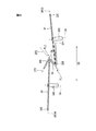
- FIG. 1 is a schematic plan view of a component manufacturing apparatus according to an embodiment of the present invention.
- the schematic side view of the component manufacturing apparatus of FIG. FIG. 3 is a sectional view taken along line III-III in FIG. 1.
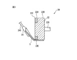
- FIG. 4 is a sectional view taken along line IVA-IVA in FIG. 1.
- FIG. 4 is a sectional view taken along line IVB-IVB in FIG. 1.
- FIG. 6B is a cross-sectional view of the sheet member of FIG. 6A. Sectional drawing of the sheet
- the rear view of the disposable diaper formed using the waist part of the disposable diaper manufactured with the component manufacturing apparatus which concerns on embodiment of this invention.
- a component manufacturing apparatus 1 schematically shown in FIGS. 1 and 2 is used.
- the component manufacturing apparatus 1 according to the present embodiment is configured to fold and process the sheet member S including the nonwoven fabric SN, the elastic member SE, and the film sheet SF that are continuously conveyed in the conveyance direction MD.
- the component of the absorbent article manufactured in the present embodiment is a waist part DW of the disposable diaper D.
- the configuration of the sheet member S and the disposable diaper D will be described in detail later.
- the sheet member S is conveyed in a state where the front surface is directed to the upper side and the back surface is directed to the lower side.
- the component manufacturing apparatus 1 includes an adhesive application device 10 that performs an adhesive application process, a preliminary folding device 20 that performs a preliminary folding process, a folding device 30 that performs a pressing process, and a folding process that performs a folding process. And a stacking device 40. These steps will be described in detail later.
- the adhesive application device 10 includes a surface adhesive application device 12 that applies an adhesive to the surface of the sheet member S, and a back surface adhesive application device 14 that applies an adhesive to the back surface of the sheet member S. Composed. As shown in FIG. 5, the front surface adhesive coating device 12 and the back surface adhesive coating device 14 are arranged in the transport direction MD with the width in the transverse direction CD orthogonal to the transport direction MD at the same transport direction MD position of the sheet member S. Apply adhesive intermittently.
- FIG. 5 is a plan view of the sheet member S before being folded and in a state where the adhesive SA is applied to the front surface FT and the back surface FB by the adhesive application device 10.
- the adhesive application device 10 may be a coater, a slit nozzle, or the like that applies an adhesive by directly contacting the surface of the sheet member S, or is sprayed and dropped on the surface of the sheet member S.
- the spray may be applied indirectly to the surface of the sheet member S.
- the adhesive is a hot melt adhesive.
- any adhesive may be used as long as it is suitable for manufacturing absorbent articles.
- the pre-folding device 20 includes a pressing roller 22 and a folding guide roll 24 in this embodiment.
- the pressing roller 22 is a roller that presses one side in the width direction of the sheet member S from above to prevent a positional deviation of the sheet member S in the transverse direction CD and gives a preliminary fold line along the conveying direction MD. .
- the pressing roller 22 is rotationally driven around a shaft 22S that supports the pressing roller 22 from one side by a rotational driving device (not shown) such as a motor at a circumferential speed that is substantially the same as the conveying speed of the sheet member S.
- the first surface 22A of the pressing roller 22 that comes into contact with the center in the width direction of the sheet member S is formed of a smooth Teflon (registered trademark) material.
- the pressing roller 22 is positioned so that the end 22E in the width direction of the pressing roller 22 matches the center line CL in the width direction of the sheet member S.
- the outer surface 22B that contacts the width direction end portion side of the sheet member S is roughened with unevenness of, for example, about several hundred ⁇ m, such as a paper file.
- the folding guide roll 24 is a free roll that can freely rotate around the shaft 24S. As shown in FIG. 3, the folding guide roll 24 extends obliquely with respect to the transverse direction CD from the side of the sheet member S toward the lower side, and the other side in the width direction of the sheet member S is the folding guide roll 24. The sheet member S can be guided so as to be lifted to the surface FT side of the sheet member S.
- the folding device 30 is located on both sides of the sheet member S in the width direction, and includes a first pushing member 32 located on the pressing roller 22 side and a second pushing member 34 located on the folding guide roll 24 side. Is done.
- the first pushing member 32 and the second pushing member 34 have a disk shape in the present embodiment, and have a particularly thin disk shape.
- the first pushing member 32 and the second pushing member 34 are solid, but a hole may be formed in a part of them for weight reduction, or the hollow pushing member 32, 34 may be formed.
- the disc shape of the first pushing member 32 and the second pushing member 34 extends in the direction of the extending planes EP32 and EP34 of the disc shape. As shown in FIGS. 4A and 4B, the first pushing member 32 and the second pushing member 34 have outer peripheral portions 32E and 34E positioned on the extending planes EP32 and EP34 in which these disk shapes extend. Thus, the sheet member S is pushed in. In the present embodiment, the first pushing member 32 and the second pushing member 34 overlap in the transverse direction CD.
- the extending planes EP32 and EP34 of the first pushing member 32 and the second pushing member 34 are not parallel to each other. More specifically, the portion of the second pushing member 34 that extends toward the first pushing member 32 in the disc-like extending plane EP 34 has a disc-like extending plane EP 32 of the first pushing member 32. Intersect.
- the outer peripheral portions 32E and 34E of the first pushing member 32 and the second pushing member 34 are preferably formed or covered with a hardly adhesive material.
- the outer peripheral portions 32E and 34E are covered with a fluorine resin material by plasma coating.
- the hard-to-adhere material is preferably a fluorine-based resin material or a silicon-based resin material.
- coating by painting or the like may be used as a method of coating the hard-to-adhere material on the outer peripheral portions 32E and 34E.
- the first pushing member 32 and the second pushing member 34 are shafts 32S and 34S extending on the disk-shaped central axis CA of the first pushing member 32 and the second pushing member 34, respectively. Are attached to be rotatable around the central axis CA.
- the folding device 40 includes a pair of press rollers 42 that press the sheet member S from the front and back surfaces and fold the sheet member S folded by the folding device 30.
- FIGS. 6A and 6B respectively show a plan view and a cross-sectional view of the sheet member S in a state before the adhesive application step and before the adhesive SA is applied.
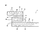
- FIG. 7 shows a cross-sectional view of the sheet member S after being folded into an outer trifold by the folding device 40.
- the broken line indicates an adhesive, which is an adhesive other than the adhesive SA applied to the sheet member S in the adhesive application step, and the folded portions of the nonwoven fabric SN are connected to each other.
- the reference symbol HM is attached to the adhesive that bonds the nonwoven fabric SN and the film sheet SF.
- a tension necessary for conveying the sheet member S linearly is applied to the sheet member S in the conveyance direction MD.
- the sheet member S is continuously and repeatedly formed in units of one product length Lp of the waistline portion DW.
- the sheet member S is applied to the periphery in a stretched state with the non-woven fabric SN folded at one end thereof (the left end in FIG. 6B), the film sheet SF fixed between the non-woven fabrics SN by an adhesive, and the like. And an elastic member SE fixed between the nonwoven fabrics SN by the adhesive.
- the elastic force of the elastic member SE acts on the portion of the sheet member S where the elastic member SE is attached.
- the generated strain is different even when the same external force is applied to the portion of the sheet member S where the elastic member SE is attached.
- the portion of the sheet member S to which the film sheet SF is attached is also different in rigidity and overall thickness as compared to the portion to which the film sheet SF is not attached, so that even if the same external force is applied.
- the strain is different. That is, it can be said that the sheet member S according to the present embodiment includes portions having different elastic strain characteristics in the direction in which the sheet member S expands.
- the method according to this embodiment is performed in the order of a sheet member manufacturing process, an adhesive application process, a preliminary folding process, a pushing process, and a folding process.
- a sheet member manufacturing process is performed. Since the sheet member manufacturing process is the same as the method of manufacturing a general disposable diaper girth member including a film sheet, only a brief description will be given below.
- the sheet member manufacturing process first, the nonwoven fabric SN wound around the nonwoven fabric roll is unwound, an adhesive is applied thereon, and the nonwoven fabric SN is unrolled in advance along the direction of unwinding.
- the elastic member SE that is present is joined.
- the film sheet SF having the bonding surface coated with an adhesive is bonded to a predetermined position on the unwound nonwoven fabric SN.
- nonwoven fabric SN is folded up twice and sheet member S is formed.
- the adhesive application step is performed after the sheet member manufacturing step.
- the adhesive application process when the sheet member S is conveyed in the conveyance direction MD from the upstream side of the component manufacturing apparatus 1 and passes through the adhesive application apparatus 10, the front surface adhesive application apparatus 12 and the back surface adhesive application apparatus 14 are used.
- a hot melt adhesive is applied to a predetermined position of the sheet member S.
- the position where the adhesive is applied to the sheet member S is between positions pushed by the first pushing member 32 and the second pushing member 34 with respect to the transverse direction CD. That is, in the adhesive application process of the present embodiment, the adhesive SA is applied to both sides of the sheet member in the portion between the fold lines FL1 and FL2 (FIG. 5) that fold the sheet member S in the outer pressing process described later. Apply.
- a preliminary folding step is performed after the adhesive application step.
- the preliminary folding step one side in the width direction of the sheet member S conveyed by the pressing roller 22 is pressed from above, and the other in the width direction of the sheet member S is lifted to the surface side of the sheet member S by the folding guide roll 24.
- the sheet member S can be prevented from shifting in the transverse direction CD. Thereby, the sheet member S can be conveyed linearly. As a result, a preliminary folding line can be applied to the position in the desired transverse direction CD of the sheet member S along the width direction center line CL of the sheet member S in the present embodiment by the pressing roller 22.
- the other side in the width direction of the sheet member is parallel to the conveying direction MD by the folding guide roll 24, and in the present embodiment, the sheet member S is aligned along the center line CL in the width direction of the sheet member S. Lift to the surface side of the member S.
- the pushing process is performed after the preliminary folding process.
- the sheet member S continuously conveyed in the conveying direction MD is transferred from the front surface FT by the first pressing member 32 and from the back surface by the second pressing member 34.
- the first pushing member 32 and the second pushing member 34 are positioned in the transverse direction CD across the adhesive SA applied to the front surface FT and the back surface FB of the sheet member S in the adhesive application step.
- the sheet member S is pushed in while being guided.
- the pushing step a part of the first pushing member 32 and the second pushing member 34 that moves as the sheet member S is conveyed, and in the present embodiment, the first pushing member 32 and the first pushing member 32 are moved.
- the sheet member S is pushed in by the disk-shaped outer peripheral portions 32E and 34E of the second pushing member 34.
- the pushing of the sheet member S by the outer peripheral portions 32E and 34E is caused by the disk shape of the first pushing member 32 and the second pushing member 34.
- the outer peripheral portions 32E and 34E gradually protrude toward each other in the transverse direction CD as the sheet member S advances in the conveyance direction MD from the conveyance direction position in FIG. 4B to the conveyance direction position in FIG. 4A. It will be.
- 4B is a position where the outer peripheral portion 34E of the second pushing member 34 just contacts the back surface FB of the sheet member S.
- 4A is a position where the first pushing member 32 and the second pushing member 34 push the sheet member S most in the transverse direction CD. That is, in the pushing process, as the sheet member S advances in the conveyance direction MD, the outer peripheral portions 32E and 34E approach each other in the transverse direction CD from the state of FIG. 4B, overlap, and pass each other toward the state of FIG. Further, the sheet member S is gradually pushed out in the transverse direction CD. As a result, as shown in FIG. 4A, the sheet member S can be pushed in and bent into a Z-shaped cross section along the fold lines FL1 and FL2.
- the first pushing member 32 and the second pushing member 34 are rotationally driven by a rotational drive mechanism (not shown) such as a motor connected to the shafts 32S and 34S in the present embodiment.
- the rotation driving mechanism is, for example, a servo motor, and servo-controlled so that the peripheral speeds of the first pressing member 32 and the second pressing member 34 are the same as the conveying speed of the sheet member S.
- the first pushing member 32 and the second pushing member 34 are rotationally driven by any other rotational drive mechanism as long as the outer peripheral portions 32E and 34E move as the sheet member S is conveyed. It does not have to be connected to the rotational drive mechanism as long as it can rotate freely.
- the outer peripheral portions 32E and 34E push the sheet member S in a position where the outer peripheral portions 32E and 34E do not touch the adhesive SA applied to the sheet member S in the adhesive application step.
- the first pushing member 32 and the second pushing member 34 are arranged.
- the folding process is performed after the pushing process.
- the sheet member S folded in the pushing process is folded into an outer trifold shape by the folding apparatus 40.
- the folding device 40 is a pair of press rollers, and the sheet member S can be folded by pressing the conveyed sheet member S from above and below.
- the sheet member S of the present embodiment folded in the folding step is disposed on the waistline portion DW of the disposable diaper that covers the waistline of the wearer when worn as described above, particularly on the back side of the waistline portion DW as shown in FIG. Used for parts.
- the crotch passes through the crotch from the wearer's stomach side to the back side when worn so that the conveying direction of the sheet member S matches the waist direction of the disposable diaper.
- the sheet member S is attached to the crotch part DC of the disposable diaper D that extends and covers the crotch of the wearer.
- a portion SB that is a folded portion of the sheet member S and is not applied with the adhesive SA formed by intermittently applying the adhesive SA in the conveyance direction MD in the adhesive application process is joined in the folding process.
- a pocket DP that can be opened toward the crotch is formed.
- the pocket DP can accommodate excrement such as loose stool, for example, loose stool, which the wearer may sit or lie down and be pushed up by body pressure and leak from the back side portion of the waist opening DWO. it can. Thereby, it is possible to suppress excrement having a low viscosity from leaking from the waist opening DWO.
- the film sheet SF is arrange
- the film sheet SF is made of plastic, but any material can be used as long as the excrement accommodated in the pocket DP can be prevented from oozing through the nonwoven fabric SN.
- a water-repellent nonwoven fabric may be used.
- the sheet member S according to this embodiment is obtained by attaching the elastic member SE and the film sheet SF to the nonwoven fabric SN as described above.
- an external force is applied to the sheet member S by the edge of the swash plate member of the bending jig.
- the sheet member S according to the present embodiment includes a portion having different elastic strain characteristics in the direction in which the sheet member S expands as described above due to the configuration thereof.
- the deformation of the sheet member S due to an external force applied from the edge of the swash plate member is not constant. As a result, the conveyance of the web member may meander and the sheet member may not be bent as desired.
- the sheet member S is bent by the outer peripheral portions 32E and 34E of the disk-shaped first pushing member 32 and the second pushing member 34. Therefore, as described above, in the bending apparatus 30, the sheet member S is bent by gradually pushing the sheet member S from the front surface FT and the back surface FB in the transverse direction CD. At this time, in the pushing step, the peripheral speeds of the first pushing member 32 and the second pushing member 34 are the same as the conveying direction of the sheet member S, so that the first pushing member 32 and the second pushing member 34 Friction hardly occurs between the outer peripheral portions 32E and 34E and the sheet member S.
- the sheet member S in order to fold the sheet member S in the outer three with a conventional bending jig, the sheet member S needs to be folded twice. At this time, in the folding process, a manufacturing error may occur at each of the two folding positions.
- the two folding steps are performed at once by the first pushing member 32 and the second pushing member 34 whose relative positions are fixed, so the folding position Almost no relative error occurs. Therefore, as compared with the conventional bending by the bending jig, the method according to the present embodiment can reduce the error of the bending position, and consequently reduce the dimensional error after the sheet member S is folded. Can do.
- the first pushing member 32 and the second pushing member 34 have a disk shape, and the outer peripheral portion 32E moves along with the transport movement of the sheet member S.
- the sheet member S is pushed in by 34E. Accordingly, as described above, the sheet member S can be pushed in while being guided by the outer peripheral portions 32E and 34E gradually projecting in the transverse direction CD. As a result, rapid deformation of the sheet member S along the conveyance direction MD can be suppressed, and as a result, the sheet member S can be bent into a shape including an outer trifold as desired.
- the disk-shaped extending planes EP32 and EP34 of the first pushing member 32 and the second pushing member 34 are not parallel to each other. More specifically, the portion of the second pushing member 34 that extends toward the first pushing member 32 in the disc-like extending plane EP 34 has a disc-like extending plane EP 32 of the first pushing member 32. Intersect. Accordingly, the outer peripheral portions 32E and 34E abut against the sheet member S as compared with the case where the disk-shaped extending planes EP32 and EP34 of the first pushing member 32 and the second pushing member 34 are parallel to each other.
- the portions of the sheet member S to be folded approach each other in the thickness direction of the sheet member S (the direction perpendicular to the transverse direction CD and in the vertical direction in FIG. 4A and FIG. 4B).
- the sheet member S can be bent as it goes.
- the sheet member S can be pushed and folded so as to approach the shape in which the sheet member is finally folded, and as a result, the sheet member can be folded and folded into a shape including the outer trifold as desired. .
- the disc-shaped extending plane EP32 of the first pushing member 32 and the extending planes EP1 and EP2 of the adjacent sheet member S are provided. They are not parallel to each other.
- the disc-shaped extending plane EP34 of the second pushing member 34 and the extending planes EP2 and EP3 of the adjacent sheet member S are not parallel to each other.
- the first pushing member 32 is located at the center portion located on the central axis CA side in the radial direction with respect to the disk-shaped outer peripheral portions 32 E and 34 E.
- bolts or nuts for attaching the second pushing member 34 to the shafts 32S, 34S are attached.
- the said center part may not be formed with the material similar to the outer peripheral parts 32E and 34E from a viewpoint of cost, for example, may be formed with the bare metal etc., for example.
- the sheet member S when the sheet member S comes into contact with the central portion, the sheet member S is caught in the central portion, and the sheet member S is contaminated, or in the worst case, the sheet member S may be broken. There is.
- the sheet member S is located at the central portion located on the radial center axis CA side with respect to the outer peripheral portions 32E and 34E of the first pushing member 32 and the second pushing member 34. The sheet member S is prevented from contacting. As a result, the sheet member S can be conveyed without breaking.
- the width direction of the sheet member S is controlled by the folding guide roll 24 while pressing one side in the width direction of the sheet member S conveyed by the pressing roller 22 from above.
- a pre-folding step of lifting the other side to the surface side of the sheet member S is performed.
- the sheet member S can be bent in advance in the shape of a cross-section “ ⁇ ”, so that the second pushing member 34 can easily push the sheet member S from the back surface FB side of the sheet member.
- the sheet member can be folded into a shape including an outer trifold as desired.
- the outer peripheral portions 32E and 34E of the first pushing member 32 and the second pushing member 34 are formed or covered with a hardly adhesive material.
- the adhesive HM is used to join the elastic member SE or the film sheet SF to the nonwoven fabric SN, and the sheet is removed from the nonwoven fabric SN at a place where the application amount is excessive. It can suppress that the adhesive agent exposed to the member S surface adheres to the outer peripheral parts 32E and 34E, and grows. As a result, the adhesive adhering to the outer peripheral portions 32E and 34E adheres to the portion of the sheet member S where the adhesive is not expected to be applied, thereby reducing the function of the sheet member S, or the subsequent line.
- the same effect can be exhibited when the application position of the adhesive applied to the front surface FT and the back surface FB of the sheet member S is shifted and contacts the outer peripheral portions 32E and 34E. it can.
- the front surface FT and the back surface FB of the sheet member S at the portion between the fold lines FL1 and FL2 that fold the sheet member S in the folding process before the pushing process. And an adhesive application step of applying an adhesive to both of them.
- the folded portions of the sheet member S are joined. Thereby, the shape of the folded sheet
- each member of the folding device includes a portion that moves as the sheet member S is transported, and if the sheet member S is pushed by the portion and bent as desired, the member has a disk shape. It does not have to be.
- an endless belt that moves along the trajectories of the outer peripheral portions 32E and 34E of the first pushing member 32 and the second pushing member 34 is moved to the first pushing member 32 and the second pushing member 34. The sheet member S is pushed in and bent by the endless belt.
- the part extended to the 1st pushing member 32 side among the disk shaped extension plane EP34 of the 2nd pushing member 34 is the disk shaped extension of the 1st pushing member 32.
- FIG. Crosses the plane EP32.
- the portion extending to the second pushing member 34 side of the disc-like extending plane EP32 of the first pushing member 32 is the disc-like extending plane of the second pushing member 34. You may make it cross
- the disk-shaped extending planes EP32 and EP34 of the first pushing member 32 and the second pushing member 34 can be used. May be parallel to each other.
- a portion of the disc-shaped extending plane EP34 of the second pushing member 34 that extends to the opposite side of the first pushing member 32 is a disc-shaped extending plane EP32 of the first pushing member 32.
- a portion extending on the opposite side of the second pushing member 34 of the disk-like extending plane EP32 of the first pushing member 32 may intersect with the disk shape of the second pushing member 34. You may make it cross
- the extending planes EP32 and EP34 of the first pushing member 32 and the second pushing member 34 and the extending planes EP1, EP2 and EP3 of the adjacent sheet member S are parallel to each other. is not. However, if the center part of the 1st pushing member 32 and the 2nd pushing member 34 is formed so that the sheet
- the plane EP32 may be parallel to the extending planes EP1 and EP2 of the adjacent sheet member S, and the disk-shaped extending plane EP34 of the second push-in member 34 and the adjacent sheet member S portion.
- the extending planes EP2 and EP3 may be parallel to each other.
- the sheet member S conveyed by the pressing roller 22 is pressed from above, and one side in the width direction of the sheet member S is lifted to the surface side of the sheet member S by the folding guide roll 24. Yes.
- one side in the width direction of the sheet member S conveyed by the pressing roller 22 is pushed up from the bottom, and the other in the width direction of the sheet member S is pushed down to the back side of the sheet member S by the folding guide roll 24. it can.
- seat member S can be previously bent by the cross-sectional " ⁇ " shape like the above-mentioned embodiment.
- the sheet member S can be easily pushed in by the first pushing member 32 and the second pushing member 34.
- the preliminary folding step may not be performed. if the first pushing member 32 and the second pushing member 34 are configured so that the sheet member S can be pushed easily, the preliminary folding step may not be performed. .
- the outer peripheral portions 32E and 34E of the first pushing member 32 and the second pushing member 34 are formed or covered with a hardly adhesive material.
- the outer peripheral portions 32E and 34E of the first pushing member 32 and the second pushing member 34 that is, the portions for pushing the sheet member S of the first pushing member 32 and the second pushing member 34 are formed of a hardly adhesive material. Or it may not be covered. This is because it is sufficient that the adhesive adheres to the portion and grows up, for example, by precisely controlling the application amount and the application position of the adhesive.
- the method according to the above-described embodiment includes an adhesive application step.
- the method according to the present invention may not include an adhesive application step.
- the folded portions of the sheet member S are welded and bonded during the folding process or by pressing while being heated by an embossing roll after the folding process.
- the sheet member S is folded in an outer trifold, but the present invention is not limited to this.
- the folding device 30 can include three or more pushing members, and the sheet member S can be folded into a bellows shape. Since the sheet member S folded in this way includes an outer tri-folded portion, the method as described above is also included in the method of the present invention.
- the position at which the sheet member S is bent is not limited to the positions of the above-described fold lines FL1, FL2, but can be freely set according to the design of the parts of the absorbent article to be manufactured.
- the composite sheet can be bent at a desired location by adjusting the dimensions and installation positions of the components of the pre-folding device 20 and the folding device 30.
- the composite sheet folded by the method and apparatus for manufacturing a part for an absorbent article of the present invention is not limited to the composite sheet S according to the above-described embodiment.
- the structure of a composite sheet can be changed freely with the components of the absorbent article to manufacture.
- the manufactured absorbent article component is the waistline portion DW of the disposable diaper D, but the present invention is not limited to this.
- the absorbent article may be a sanitary napkin, a urine absorbing pad, or the like, and a method of folding the absorbent article part into a shape including an outer trifold using the above-described method is also included in the present invention. .
Landscapes
- Health & Medical Sciences (AREA)
- Engineering & Computer Science (AREA)
- Life Sciences & Earth Sciences (AREA)
- Biomedical Technology (AREA)
- Heart & Thoracic Surgery (AREA)
- Vascular Medicine (AREA)
- Epidemiology (AREA)
- Animal Behavior & Ethology (AREA)
- General Health & Medical Sciences (AREA)
- Public Health (AREA)
- Veterinary Medicine (AREA)
- Manufacturing & Machinery (AREA)
- Mechanical Engineering (AREA)
- Absorbent Articles And Supports Therefor (AREA)
Abstract
本発明は、拡がる方向に弾性ひずみ特性が互いに異なる部分を含むシート部材(S)から吸収性物品用の部品を製造する方法に関する。本発明は、搬送方向(MD)に連続的に搬送されているシート部材を、第一の押し込み部材(32)がシート部材の表面(FT)からそして第二の押し込み部材(34)がシート部材の裏面(FB)から、搬送方向と直交するシート部材の横断方向(CD)にずれた位置において、第一の押し込み部材及び第二の押し込み部材の一部であって、シート部材の搬送移動に伴って移動する部分で押し込んで、搬送方向に沿って折り曲げる押し込み工程と、押し込み工程によって折り曲げられたシート部材を、外三つ折りを含む形状に折り重ねる折り重ね工程と、を含む。
Description
本発明は、外三つ折りを含む形状にシート部材を折り重ねる工程を含む、吸収性物品用の部品を製造する方法に関する。
従来から、不織布などの一様なシート形状の部材を折り曲げるための、斜板部材を含む曲げ治具が開示されている(例えば、特許文献1の段落[0066]~[0069]参照)。こうした曲げ治具では、搬送方向に搬送されているシート部材の幅方向の一端部を内側に徐々に引き込むことによって、シート部材の曲げ工程が行われる。シート部材の幅方向の一端部を内側に徐々に引き込むために、斜板部材のエッジによってシート部材を内側に引き込むように、シート部材が拡がる方向に外力を加えることが一般的に行われている。
このような曲げ治具によってシート部材を折り曲げる場合では、折り曲げる対象が一様なシート部材であれば、斜板部材のエッジによって一定の外力を加えれば所望のようにシート部材を折り曲げることができる。しかしながら、シート部材が、例えば弾性部材や別のフィルムシートなどを部分的に含むことにより、シート部材が拡がる方向への外力によるひずみが一様でない場合には、斜板部材のエッジによって付与される外力によるシート部材の変形が一定にならない場合がある。その結果、ウェブ部材の搬送が蛇行して所望のようにシート部材を折り曲げることができない場合がある。
しかしながら今日では、使い捨てオムツや生理用ナプキンなどの吸収性物品の部品を製造する過程において、吸収性物品に特定の機能を付与するために、例えば部分的に弾性部材やフィルムシートなどを部分的に含む複合材料であるシート部材を折り曲げる、特に外三つ折りを含む形状に折り重ねることが求められている。
したがって、本発明の目的は、シート部材が拡がる方向に弾性ひずみ特性が互いに異なる部分を含むシート部材を所望のように外三つ折りを含む形状に折り重ねる、吸収性物品用の部品を製造する方法を提供することにある。
上記課題を解決するために、本発明によれば、
表面と裏面とを有するシート部材であって、前記シート部材が拡がる方向に弾性ひずみ特性が互いに異なる部分を含むシート部材から吸収性物品用の部品を製造する方法であって、
第一の押し込み部材と、第二の押し込み部材とを有する折り曲げ装置を用いて、搬送方向に連続的に搬送されている前記シート部材を、前記第一の押し込み部材が前記シート部材の表面からそして前記第二の押し込み部材が前記シート部材の裏面から、前記搬送方向と直交する前記シート部材の横断方向にずれた位置において、前記第一の押し込み部材及び前記第二の押し込み部材の一部であって、前記シート部材の搬送移動に伴って移動する部分で押し込んで、前記搬送方向に沿って折り曲げる押し込み工程と、
前記押し込み工程によって折り曲げられた前記シート部材を、外三つ折りを含む形状に折り重ねる折り重ね工程と、
を含む、
方法が提供される。
表面と裏面とを有するシート部材であって、前記シート部材が拡がる方向に弾性ひずみ特性が互いに異なる部分を含むシート部材から吸収性物品用の部品を製造する方法であって、
第一の押し込み部材と、第二の押し込み部材とを有する折り曲げ装置を用いて、搬送方向に連続的に搬送されている前記シート部材を、前記第一の押し込み部材が前記シート部材の表面からそして前記第二の押し込み部材が前記シート部材の裏面から、前記搬送方向と直交する前記シート部材の横断方向にずれた位置において、前記第一の押し込み部材及び前記第二の押し込み部材の一部であって、前記シート部材の搬送移動に伴って移動する部分で押し込んで、前記搬送方向に沿って折り曲げる押し込み工程と、
前記押し込み工程によって折り曲げられた前記シート部材を、外三つ折りを含む形状に折り重ねる折り重ね工程と、
を含む、
方法が提供される。
本願明細書では、シート部材について「弾性ひずみ特性」という用語を用いて、外力によるシート部材の変形の特性を示す。ここで、「弾性ひずみ特性が異なる」とは、一定の外力によるシート部材の変形の度合いが異なることを意味している。さらにいえば、「シート部材が拡がる方向に弾性ひずみ特性が互いに異なる部分を含む」とは、不織布の製造誤差による目付けムラなどによるものではなく、例えば不織布に部分的に弾性部材や別体のシートなどが取り付けられていることにより、シート部材が拡がる方向に剛性や弾性係数が互いに異なる部分が存在することを意味している。
さらに、前記横断方向に互いに重なる前記第一の押し込み部材及び前記第二の押し込み部材を用いて、前記押し込み工程を行うことが好ましい。第一の押し込み部材及び第二の押し込み部材が横断方向に互いに重なるという位置関係によって、外三つ折りを含む形状にシート部材を折り曲げることができる。
さらに、前記第一の押し込み部材及び前記第二の押し込み部材は共に円盤形状であって前記円盤形状の中心軸線回りに回転可能であり、前記押し込み工程では、前記第一の押し込み部材及び前記第二の押し込み部材の円盤形状が延在する平面上に位置する外周部分によって、前記シート部材を押し込むことが好ましい。押しこみ部材が回転可能な円盤形状であるので、シート部材の搬送移動に伴って移動する外周部分によってシート部材を徐々に押し込んで折り曲げることができる。その結果、シート部材を折り曲げる際に、シート部材の急激な変形を抑制することができ、ひいてはシート部材を所望のように外三つ折りを含む形状に折り曲げることができる。
さらに、前記第一の押し込み部材の円盤形状の延在平面のうちの前記第二の押し込み部材側に延在する部分が前記第二の押し込み部材の円盤形状の延在平面と交差し、又は前記第二の押し込み部材の円盤形状の延在平面のうちの前記第一の押し込み部材側に延在する部分が前記第一の押し込み部材の円盤形状の延在平面と交差する、前記第一の押し込み部材及び前記第二の押し込み部材を用いて、前記押し込み工程を行うことが好ましい。このように、第一の押し込み部材及び第二の押し込み部材の円盤形状の延在平面の角度を互いに平行ではない角度に調整することにより、これらの外周部分がシート部材に当接してさらに押し込んで行くにつれて、折り重ねられるシート部材の部分同士がシート部材の厚さ方向に近接していって、最終的にシート部材を折り重ねる形状に近づくように、シート部材を折り曲げることができる。その結果、シート部材を所望のように外三つ折りを含む形状に折り曲げて折り重ねることができる。
さらに、前記第一の押し込み部材及び前記第二の押し込み部材の円盤形状の延在平面と、隣接する前記シート部材の部分の延在平面とが互いに平行ではない、前記第一の押し込み部材及び前記第二の押し込み部材を用いて、前記押し込み工程を行うことが好ましい。これにより、シート部材が第一の押し込み部材及び第二の押し込み部材の円盤形状の外周部分よりも半径方向の中心軸側に位置する中央部に接触して、シート部材が引っかかったり、場合によっては破断したりすることを防止できる。
前記押し込み工程では、前記第一の押し込み部材及び前記第二の押し込み部材の周速が前記シート部材の搬送速度と同一になるように、前記第一の押し込み部材及び前記第二の押し込み部材を回転駆動することが好ましい。これにより、シート部材が第一の押し込み部材及び第二の押し込み部材の円盤形状の外周部分上で摺動することを抑制することができる。その結果、外周部分32E、34Eからシート部材Sに対して摩擦がほぼ発生せず、シート部材Sが拡がる方向に外力がほとんど発生しないので、シート部材の搬送が蛇行せずに、シート部材を所望の位置で折り曲げることができる。
前記押し込み工程の前に、前記シート部材の搬送方向に平行な折り曲げ線に沿って前記シート部材の幅方向の一方を、前記シート部材の表面側に持ち上げ又は裏面側に押し下げる予備折り工程をさらに含むことが好ましい。これにより、シート部材を第一の押し込み部材及び第二の押し込み部材によって折り曲げる前に、シート部材を所望のように折り曲げ易い形状に予めしておくことができる。それにより、シート部材を所望のように外三つ折りを含む形状に折り曲げることができる。
少なくとも前記シート部材に接触する部分が、難接着材料によって形成又は被覆されている前記第一の押し込み部材及び前記第二の押し込み部材を用いて、前記押し込み工程を行うことが好ましい。押し込み工程の前段階でシート部材に接着剤や粘着剤等を使用していた場合において、第一の押し込み部材及び第二の押し込み部材のシート部材に接触する部分に接着剤や粘着剤が付着して、後続のシート部材が付着した接着剤や粘着剤等によって汚染される場合がある。しかしながら、上記構成により、第一の押し込み部材及び第二の押し込み部材のシート部材に接触する部分に難接着材料を配置することによって、当該部分への接着剤や粘着剤等の付着を抑制することができる。その結果、上述のような後続するシート部材の汚染を抑制することができる。
前記押し込み工程の前に、前記折り重ね工程において前記シート部材を外三つ折りする折り曲げ線同士の間の部分において、前記シート部材の表面及び裏面の一方又は両方に接着剤を塗布する接着剤塗布工程を含み、前記折り重ね工程では、前記シート部材の折り重ねられた部分を接合することが好ましい。これにより、シート部材を折り重ねた部分同士を接着することができ、それにより折り重ねたシート部材の形状を保持することができる。
さらに、上記課題を解決するために、本発明によれば、
表面と裏面とを有するシート部材であって、前記シート部材が拡がる方向に弾性ひずみ特性が互いに異なる部分を含むシート部材から吸収性物品用の部品を製造する装置であって、
第一の押し込み部材と第二の押し込み部材とを有する折り曲げ装置であって、
搬送方向に連続的に搬送されている前記シート部材を、前記第一の押し込み部材が表面からそして前記第二の押し込み部材が裏面から、前記搬送方向と直交する前記シート部材の横断方向にずれた位置において、前記第一の押し込み部材及び前記第二の押し込み部材の一部であって、前記シート部材の搬送移動に伴って移動する部分で押し込んで、前記搬送方向に沿って折り曲げる、
折り曲げ装置と、
前記折り曲げ装置によって折り曲げられた前記シート部材を、外三つ折りを含む形状に折り重ねる折り重ね装置と、
を備える、
装置が提供される。
表面と裏面とを有するシート部材であって、前記シート部材が拡がる方向に弾性ひずみ特性が互いに異なる部分を含むシート部材から吸収性物品用の部品を製造する装置であって、
第一の押し込み部材と第二の押し込み部材とを有する折り曲げ装置であって、
搬送方向に連続的に搬送されている前記シート部材を、前記第一の押し込み部材が表面からそして前記第二の押し込み部材が裏面から、前記搬送方向と直交する前記シート部材の横断方向にずれた位置において、前記第一の押し込み部材及び前記第二の押し込み部材の一部であって、前記シート部材の搬送移動に伴って移動する部分で押し込んで、前記搬送方向に沿って折り曲げる、
折り曲げ装置と、
前記折り曲げ装置によって折り曲げられた前記シート部材を、外三つ折りを含む形状に折り重ねる折り重ね装置と、
を備える、
装置が提供される。
上記発明によれば、シート部材が拡がる方向に弾性ひずみ特性が互いに異なる部分を含むシート部材であっても、前記第一の押し込み部材及び前記第二の押し込み部材の一部であって、シート部材の搬送移動に伴って移動する部分で押し込み、折り曲げられたシート部材を折り曲げる。その結果、シート部材を、所望のように外三つ折りを含む形状に折り重ねることができる。
本発明は上述の図面を参照しつつより詳細に記載される。なお、これらの図面は、本発明の理解を容易にすると共に図面の記載を簡略化するために、実際の構成要素の大きさ、縮尺、形状と同一に描かれていない場合があることに留意されたい。
これより、本発明の実施形態について説明する。本実施形態に係る吸収性物品用の部品を製造する方法では、図1及び図2に概略的に示す部品製造装置1が用いられる。本実施形態に係る部品製造装置1は、搬送方向MDに連続的に搬送される、不織布SN、弾性部材SE及びフィルムシートSFを含むシート部材Sを折り重ね加工するものである。本実施形態において製造される吸収性物品の部品は、使い捨てオムツDの胴回り部DWである。シート部材S及び使い捨てオムツDの構成については、後に詳述する。なお、本実施形態では、シート部材Sは、上側に表面が、そして下側に裏面が向けられた状態で搬送されている。
本実施形態に係る部品製造装置1は、接着剤塗布工程を行う接着剤塗布装置10と、予備折り工程を行う予備折り装置20と、押し込み工程を行う折り曲げ装置30と、折り重ね工程を行う折り重ね装置40とを備える。これらの工程については、後に詳述する。
接着剤塗布装置10は、本実施形態では、シート部材Sの表面に接着剤を塗布する表面接着剤塗布装置12と、シート部材Sの裏面に接着剤を塗布する裏面接着剤塗布装置14とから構成される。表面接着剤塗布装置12及び裏面接着剤塗布装置14は、図5に示すように、シート部材Sの同じ搬送方向MD位置に、搬送方向MDに直交する横断方向CDの幅をもって、搬送方向MDに間欠的に接着剤を適用する。なお、図5は、折り重ねられる前であって、接着剤塗布装置10によって接着剤SAが表面FT及び裏面FBに塗布された状態におけるシート部材Sの平面図である。
接着剤塗布装置10は、シート部材Sの表面に直接的に接することによって接着剤を塗布するコーターやスリットノズル等であってもよいし、シート部材Sの表面に噴霧、滴下して、接着剤をシート部材Sの表面に間接的に適用するスプレー等であってもよい。また、本実施形態では、接着剤はホットメルト接着剤である。しかしながら、接着剤は、吸収性物品の製造に適したものであればどのようなものであってもよい。
予備折り装置20は、本実施形態では押さえローラ22と折りガイドロール24とから構成される。
押さえローラ22は、シート部材Sの幅方向の一方を上から押さえて、横断方向CDのシート部材Sの位置ズレを防止しつつ、搬送方向MDに沿った予備的な折り曲げ線を付けるローラである。押さえローラ22は、片側から押さえローラ22を支持するシャフト22S回りに、シート部材Sの搬送速度とほぼ同じ周速で、モータなどの回転駆動装置(図示しない)によって回転駆動される。シート部材Sの幅方向中央側に当接する押さえローラ22の第一の表面22Aは滑らかなテフロン(登録商標)材料から形成されている。さらに、シート部材Sの幅方向中央側に当接する、押さえローラ22のシャフト22Sと反対方向の幅方向端部22EはR面取り(例えばR=1mm)されている。その結果、押さえローラ22によってシート部材Sに予備的な折り曲げ線を付与するときに、シート部材Sが幅方向端部22Eに引っかかることによってシート部材Sを傷付けることが抑制される。なおここでは、押さえローラ22の幅方向端部22Eがシート部材Sの幅方向中心線CLに合うように、押さえローラ22が位置決めされている。さらに、本実施形態では、シート部材Sの幅方向端部側に当接する外側表面22Bは、紙ヤスリのような、例えば数百μm程度の凹凸が形成されており、粗くなっている。
折りガイドロール24は、シャフト24S回りに自在に回転できるフリーロールである。折りガイドロール24は、図3に示すように、シート部材Sの側方から下方向に向かって横断方向CDに対して斜めに延びており、シート部材Sの幅方向の他方を折りガイドロール24の表面上に載せることによって、シート部材Sの表面FT側に持ち上げるようにシート部材Sをガイドすることができる。
折り曲げ装置30は、シート部材Sの幅方向両側に位置しており、押さえローラ22側に位置する第一の押し込み部材32と、折りガイドロール24側に位置する第二の押し込み部材34とから構成される。
第一の押し込み部材32及び第二の押し込み部材34は、本実施形態では円盤形状をしており、特に薄い円板形状をしている。本実施形態では、第一の押し込み部材32及び第二の押し込み部材34は中実であるが、軽量化のためにこれらの一部に穴を形成しても良いし、中空の押し込み部材32、34を形成してもよい。
第一の押し込み部材32及び第二の押し込み部材34の円板形状は、当該円板形状の延在平面EP32、EP34方向に拡がっている。そして、第一の押し込み部材32及び第二の押し込み部材34は、図4A及び図4Bに示すように、これらの円盤形状が延在する延在平面EP32、EP34上に位置する外周部分32E、34Eによって、シート部材Sを押し込むようにされている。本実施形態では、第一の押し込み部材32及び第二の押し込み部材34は横断方向CDに重なっている。そして、第一の押し込み部材32及び第二の押し込み部材34の延在平面EP32、EP34は互いに平行ではない。より具体的には、第二の押し込み部材34の円盤形状の延在平面EP34のうちの第一の押し込み部材32側に延在する部分が第一の押し込み部材32の円盤形状の延在平面EP32と交差する。
これらの第一の押し込み部材32及び第二の押し込み部材34の外周部分32E、34Eは、難接着材料によって形成又は被覆されていると好ましい。本実施形態では、外周部分32E、34Eは、プラズマコーティングによりフッ素系樹脂材料よって被覆されている。ここで、難粘着材料としては、フッ素系樹脂材料又はシリコン系樹脂材料が好ましい。また、難粘着材料を外周部分32E、34Eにコーティングする方法としては、プラズマコーティング以外にも塗装によるコーティングなどであってもよい。
第一の押し込み部材32及び第二の押し込み部材34はそれぞれ、図4Aに示すように、第一の押し込み部材32及び第二の押し込み部材34の円盤形状の中心軸線CA上を延びるシャフト32S、34Sに、中心軸線CA回りに回転可能に取り付けられている。
折り重ね装置40は、シート部材Sを表面及び裏面から押圧して、折り曲げ装置30によって折り曲げられたシート部材Sを折り重ねる一対のプレスローラ42から構成されている。
図6A及び図6Bはそれぞれ、接着剤塗布工程前の状態であって接着剤SAが塗布される前のシート部材Sの平面図及び断面図を示している。また、図7は、折り重ね装置40によって外三つ折りに折り重ねられた後のシート部材Sの断面図を示している。なお、図6B及び図7では、破線は接着剤を示しており、上記接着剤塗布工程でシート部材Sに塗布した接着剤SA以外の接着剤であって、折り返された不織布SNの部分同士を接着し、不織布SNとフィルムシートSFとを接着する接着剤には、参照記号HMを付している。また、一般的なシートの連続的な搬送と同様に、シート部材Sには、シート部材Sを直線的に搬送するために必要な張力が搬送方向MDに付与されている。
シート部材Sは、胴回り部DWの1製品長Lp単位で連続的に繰り返し形成される。シート部材Sは、その一方の端部(図6Bでは左側の端部)で折り返された不織布SNと、接着剤によって不織布SN同士の間に固定されたフィルムシートSFと、伸長状態で周囲に塗布された接着剤によって不織布SN同士の間に固定された弾性部材SEとを含む。このようなシート部材Sの構成から、シート部材Sが拡がる方向に外力が加えられると、シート部材Sの弾性部材SEが取り付けられている部分では、弾性部材SEの弾性力が作用する。したがって、シート部材Sの弾性部材SEが取り付けられていない部分と比較すると、シート部材Sの弾性部材SEが取り付けられている部分では同じ外力が加わったとしても発生するひずみが異なる。また、同様にシート部材SのフィルムシートSFが取り付けられた部分に関しても、フィルムシートSFが取り付けられていない部分と比較すると剛性や全体の厚さが異なるので、同じ外力が加わったとしても発生するひずみが異なる。つまり、本実施形態に係るシート部材Sでは、シート部材Sが拡がる方向に弾性ひずみ特性が互いに異なる部分を含むということができる。
これより、本発明の実施形態に係る吸収性物品用の部品を製造する方法について説明する。本実施形態に係る方法は、シート部材製造工程、接着剤塗布工程、予備折り工程、押し込み工程及び折り重ね工程の順に行われる。
まず、本実施形態に係る方法では、シート部材製造工程を行う。シート部材製造工程は、フィルムシートを含む一般的な使い捨てオムツの胴回り部材を製造する方法と同じであるので、以下簡単にのみ説明をする。特に図示していないがシート部材製造工程では、まず不織布ロールに巻き取られている不織布SNを巻き出し、その上に接着剤が塗布されかつ不織布SNが巻き出される方向に沿って予め伸長されている弾性部材SEを接合する。次いで、接合面に接着剤が塗布されたフィルムシートSFが、巻き出された不織布SN上の所定の位置に接合される。そして、不織布SNに弾性部材SE及びフィルムシートSFが接合された後に不織布SNが二重に折り重ねられて、シート部材Sが形成される。
本実施形態に係る方法では、シート部材製造工程に次いで接着剤塗布工程を行う。接着剤塗布工程では、部品製造装置1の上流からシート部材Sが搬送方向MDに搬送されて、接着剤塗布装置10を通過するときに、表面接着剤塗布装置12及び裏面接着剤塗布装置14によってシート部材Sの所定の位置にホットメルト接着剤を塗布する。本実施形態では、シート部材Sに対して接着剤を塗布する位置は、横断方向CDに関して、第一の押し込み部材32及び第二の押し込み部材34によって押し込まれる位置同士の間である。つまり、本実施形態の接着剤塗布工程では、後述する押し込み工程においてシート部材Sを外三つ折りする折り曲げ線FL1、FL2(図5)同士の間の部分に、シート部材の両面に接着剤SAを塗布する。
本実施形態に係る方法では、接着剤塗布工程に次いで、予備折り工程を行う。予備折り工程では、押さえローラ22によって搬送されているシート部材Sの幅方向の一方を上から押さえつつ、折りガイドロール24によってシート部材Sの幅方向の他方をシート部材Sの表面側に持ち上げる。
さらに、予備折り工程では、押さえローラ22のシャフト22S側に位置する第二の表面22Bが上述のように粗くなっているので、シート部材Sが横断方向CDにずれることを抑制することができる。これにより、シート部材Sを直線的に搬送することができる。その結果、押さえローラ22によって、シート部材Sの所望の横断方向CDの位置に、本実施形態ではシート部材Sの幅方向中心線CLに沿って、予備的な折り曲げ線を付与することができる。
本実施形態の予備折り工程では、折りガイドロール24によって、前記シート部材の幅方向の他方を、搬送方向MDに平行な、本実施形態ではシート部材Sの幅方向中心線CLに沿って、シート部材Sの表面側に持ち上げる。
本実施形態に係る方法では、予備折り工程に次いで押し込み工程を行う。押し込み工程では、図4A及び図4Bに示すように、搬送方向MDに連続的に搬送されているシート部材Sを、第一の押し込み部材32によって表面FTから、そして第二の押し込み部材34によって裏面FBから、横断方向CDにずれた位置において押し込む。さらに具体的には、第一の押し込み部材32及び第二の押し込み部材34は、接着剤塗布工程においてシート部材Sの表面FT及び裏面FBに適用された接着剤SAを隔てた横断方向CDの位置において、シート部材Sをガイドしつつ押し込む。
押し込み工程では、第一の押し込み部材32及び第二の押し込み部材34の一部であって、シート部材Sの搬送移動に伴って移動する部分で、本実施形態では第一の押し込み部材32及び第二の押し込み部材34の円盤形状の外周部分32E、34Eでシート部材Sを押し込む。このような外周部分32E、34Eによるシート部材Sの押し込みは、第一の押し込み部材32及び第二の押し込み部材34の円盤形状によって引き起こされるものである。具体的には、外周部分32E、34Eは、図4Bの搬送方向位置から図4Aの搬送方向位置にむかってシート部材Sが搬送方向MDに進むにつれて、横断方向CDに互いに向かって徐々に張り出すことになる。図4Bの搬送方向位置は、第二の押し込み部材34の外周部分34Eがシート部材Sの裏面FBにちょうど当接する位置である。図4Aの搬送方向位置は、第一の押し込み部材32及び第二の押し込み部材34がシート部材Sを横断方向CDに最も押し込む位置である。つまり、押し込み工程では、シート部材Sが搬送方向MDに進むにつれて、図4Bの状態から、外周部分32E、34Eが横断方向CDにおいて互いに近づいて、重なり、そして図4Aの状態に向かってすれ違うようにさらに張り出して、シート部材Sを横断方向CDに徐々に押し込む。その結果、図4Aに示されているように、シート部材Sを押し込んで、折り曲げ線FL1、FL2に沿って断面Z字形状に折り曲げることができる。
本実施形態では、第一の押し込み部材32及び第二の押し込み部材34は、本実施形態ではシャフト32S、34Sに接続されているモータ等の回転駆動機構(図示しない)によって回転駆動されている。ここでは回転駆動機構は例えばサーボモータであり、第一の押し込み部材32及び第二の押し込み部材34の周速が、シート部材Sの搬送速度と同じになるようにサーボ制御されている。しかしながら、第一の押し込み部材32及び第二の押し込み部材34は、その外周部分32E、34Eがシート部材Sの搬送に伴って移動するものであれば、その他どのような回転駆動機構によって回転駆動されてもよいし、自在に回転できるものであれば回転駆動機構に接続されていなくてもよい。
なお、本実施形態では、外周部分32E及び34Eが、設計上図4Aに示すように、接着剤塗布工程においてシート部材Sに塗布された接着剤SAに触れない位置においてシート部材Sを押し込むように、第一の押し込み部材32及び第二の押し込み部材34を配置する。
本実施形態では、押し込み工程に次いで折り重ね工程を行う。折り重ね工程では、押し込み工程によって折り曲げられたシート部材Sを、折り重ね装置40によって外三つ折り形状に折り重ねる。本実施形態では、折り重ね装置40は、一対のプレスローラであって、搬送されているシート部材Sを上下からプレスすることによって、シート部材Sを折り重ねることができる。
折り重ね工程で折り重ねられた本実施形態のシート部材Sは、上述のように着用時に着用者の胴回りを覆う使い捨てオムツの胴回り部DWに、特に図8に示すように胴回り部DWの背中側部分に使用される。使い捨てオムツにシート部材Sを取り付ける際には、シート部材Sの搬送方向が、使い捨てオムツの胴回り方向と一致するように、着用時に着用者の腹側から背中側に向かって股下を通過するように延びて着用者の股間を覆う使い捨てオムツDの股下部DCにシート部材Sを取り付ける。
シート部材Sの折り返し部分であって、接着剤塗布工程では接着剤SAが搬送方向MDに間欠的に塗布されることによって形成される接着剤SAが塗布されなかった箇所SBが折り重ね工程において接合されないことによって、股下に向かって開口可能なポケットDPが形成される。ポケットDPは、着用者が着座したり寝転がったりして、体圧によって押し上げられてウエスト開口部DWOの背中側部分から漏出するおそれのある、粘度の低い、例えば軟便など排泄物を収容することができる。それによって、粘度の低い排泄物がウエスト開口部DWOから漏出することを抑制することができる。
また、本実施形態に係る使い捨てオムツDでは、上記ポケットDPが形成される箇所にフィルムシートSFが配置されており、このフィルムシートSFがポケットDPに収容された排泄物が不織布SNを通して染み出すことを抑制することができる。本実施形態では、フィルムシートSFはプラスチック製のものであるが、ポケットDPに収容された排泄物が不織布SNを通して染み出すことを抑制することができるものであれば、どのような材料であってもよいし、例えば撥水性不織布などであってもよい。
これより、本実施形態に係る吸収性物品用の部品を製造する方法の作用効果について説明する。
(1) 本実施形態に係るシート部材Sは、上述のように不織布SNに弾性部材SEやフィルムシートSFが取り付けられたものである。例えば特許文献1に開示の曲げ治具を用いてシート部材Sを折り重ねる場合では、シート部材Sに当該曲げ治具の斜板部材のエッジによって外力が加えられる。本実施形態に係るシート部材Sではその構成に起因して、上述のようにシート部材Sが拡がる方向に弾性ひずみ特性が互いに異なる部分を含むので、シート部材Sを、特許文献1に開示の曲げ治具を用いて折り重ねる場合では、斜板部材のエッジから付与される外力によるシート部材Sの変形が一定にならない。その結果、ウェブ部材の搬送が蛇行して所望のようにシート部材を折り曲げることができない場合がある。
これに対して、本実施形態に係る方法では、円盤形状の第一の押し込み部材32及び第二の押し込み部材34の外周部分32E、34Eによって、シート部材Sを折り曲げる。したがって、上述のように、折り曲げ装置30では、シート部材Sを表面FT及び裏面FBから徐々に横断方向CDに押し込むことによってシート部材Sを折り曲げる。このとき、押し込み工程では、第一の押し込み部材32及び第二の押し込み部材34の周速がシート部材Sの搬送方向と同じであるので、第一の押し込み部材32及び第二の押し込み部材34の外周部分32E、34Eとシート部材Sとの間に摩擦がほとんど発生しない。言い換えれば、外周部分32E、34Eからシート部材Sに対して、シート部材Sが拡がる方向に外力がほとんど発生しない。したがって、シート部材Sが拡がる方向に弾性ひずみ特性が互いに異なる部分を含んでいるにも関わらず、シート部材Sの搬送時の蛇行が抑制される。その結果、シート部材Sを所望の位置で折り曲げることができ、ひいては製造誤差の少ない吸収性物品用の部品を製造することができる。
(2) また、従来の曲げ治具でシート部材Sを外三つ折りするためには、シート部材Sを2回折り重ねる必要がある。このとき、折り重ねる工程において、2箇所各々の折り位置に製造上の誤差が発生するおそれがある。これに対して、本実施形態に係る方法では、2箇所の折り曲げ工程を、相対的な位置が固定されている第一の押し込み部材32及び第二の押し込み部材34によって一度に行うので、折り曲げ位置の相対的な誤差はほとんど発生しない。したがって、従来の曲げ治具による折り曲げと比較すると、本実施形態に係る方法では、折り曲げ位置の誤差を小さくすることができ、ひいてはシート部材Sを折り重ねた後の寸法上の誤差を小さくすることができる。
(3) 本実施形態に係る方法の押し込み工程では、第一の押し込み部材32及び第二の押し込み部材34は円盤形状をしており、シート部材Sの搬送移動に伴って移動する外周部分32E、34Eによってシート部材Sを押し込む。これにより、上述のように、横断方向CDに徐々に張り出す外周部分32E、34Eによって、シート部材Sをガイドしつつ押し込むことができる。その結果、搬送方向MDに沿ったシート部材Sの急激な変形を抑制することができ、ひいては所望のように外三つ折りを含む形状に折り曲げることができる。
(4)本実施形態に係る方法では、第一の押し込み部材32及び第二の押し込み部材34の円盤形状の延在平面EP32、EP34が互いに平行ではない。より具体的には、第二の押し込み部材34の円盤形状の延在平面EP34のうちの第一の押し込み部材32側に延在する部分が第一の押し込み部材32の円盤形状の延在平面EP32と交差する。これにより、第一の押し込み部材32及び第二の押し込み部材34の円盤形状の延在平面EP32、EP34が互いに平行である場合と比較すると、これらの外周部分32E、34Eがシート部材Sに当接してさらに押し込んで行くにつれて、折り重ねられるシート部材Sの部分同士がシート部材Sの厚さ方向(横断方向CDに直交する方向であって、図4A及び図4Bの紙面上下方向)に近接していくようにシート部材Sを折り曲げることができる。その結果、最終的にシート部材を折り重ねる形状に近づくように、シート部材Sを押し込んで折り曲げることができ、ひいてはシート部材を所望のように外三つ折りを含む形状に折り曲げて折り重ねることができる。
(5)本実施形態に係る方法では、図4Aに示すように、第一の押し込み部材32の円盤形状の延在平面EP32と、隣接するシート部材Sの部分の延在平面EP1、EP2とが互いに平行ではない。同様に、第二の押し込み部材34の円盤形状の延在平面EP34と、隣接するシート部材Sの部分の延在平面EP2、EP3とが互いに平行ではない。ここで第一の押し込み部材32及び第二の押し込み部材34に関して、これらの円盤形状の外周部分32E、34Eよりも半径方向の中心軸線CA側に位置する中央部には、第一の押し込み部材32及び第二の押し込み部材34をシャフト32S、34Sに取り付けるボルトやナットなどが取り付けられている場合がある。また、当該中央部は、コストの観点から外周部分32E、34Eと同様の材料で形成されていない場合があり、例えば剥き出しの金属などで形成されている場合がある。これらの場合では、シート部材Sが当該中央部に接触することによって、当該中央部にシート部材Sが引っかかって、シート部材Sが汚染されたり、最悪の場合ではシート部材Sが破断したりするおそれがある。しかしながら、本実施形態に係る上記構成により、シート部材Sが、第一の押し込み部材32及び第二の押し込み部材34の外周部分32E、34Eよりも半径方向の中心軸線CA側に位置する中央部にシート部材Sが接触することが防止される。その結果、シート部材Sを破断することなく搬送することができる。
(6) 本実施形態に係る方法では、押し込み工程の前に、押さえローラ22によって搬送されているシート部材Sの幅方向の一方を上から押さえつつ、折りガイドロール24によってシート部材Sの幅方向の他方をシート部材Sの表面側に持ち上げる予備折り工程を行う。これにより、シート部材Sを予め断面「く」の字状に折り曲げておくことができ、それにより第二の押し込み部材34がシート部材の裏面FB側からシート部材Sを押し込み易くなる。その結果、シート部材を所望のように外三つ折りを含む形状に折り曲げることができる。
(7)本実施形態では、第一の押し込み部材32及び第二の押し込み部材34の外周部分32E、34Eは、難接着材料によって形成又は被覆されている。これにより、例えば、シート部材製造工程において弾性部材SEやフィルムシートSFを不織布SNに接合するために使用される接着剤HMであって、塗布量が過多になった場所で不織布SNを抜けてシート部材S表面に露出した接着剤が、外周部分32E、34Eに付着して成長することを抑制できる。その結果、外周部分32E、34Eに付着した接着剤が、接着剤が塗布されることを予定していないシート部材Sの部分に付着して、シート部材Sの機能を低下させたり、後続のライン汚染を引き起こしたりすることを抑制できる。また、接着剤塗布工程において、シート部材Sの表面FT及び裏面FBに塗布された接着剤の塗布位置がズレて、外周部分32E、34Eに接触する場合についても、同様の効果を発揮することができる。
(8) 本実施形態に係る方法では、押し込み工程の前に、折り重ね工程においてシート部材Sを外三つ折りする折り曲げ線FL1、FL2同士の間の部分において、シート部材Sの表面FT及び裏面FBの両方に接着剤を塗布する接着剤塗布工程を含む。そして、折り重ね工程において、シート部材Sの折り重ねられた部分を接合する。これにより、折り重ねたシート部材の形状を保持することができる。
上述の実施形態では、折り曲げ装置30の第一の押し込み部材32及び第二の押し込み部材34は円盤形状であった。しかしながら、本発明では、折り曲げ装置の各部材は、シート部材Sの搬送移動に伴って移動する部分を含み、当該部分によってシート部材Sを押し込んで所望のように折り曲げるものであれば、円盤形状でなくてもよい。例えば、別の実施形態では、第一の押し込み部材32及び第二の押し込み部材34の外周部分32E、34Eの軌跡に沿って移動する無端ベルトを第一の押し込み部材32及び第二の押し込み部材34の代わりに配置して、当該無端ベルトによってシート部材Sを押し込んで折り曲げる。
また、上述の実施形態では、第二の押し込み部材34の円盤形状の延在平面EP34のうちの第一の押し込み部材32側に延在する部分が第一の押し込み部材32の円盤形状の延在平面EP32と交差する。これと同様の趣旨で、第一の押し込み部材32の円盤形状の延在平面EP32のうちの第二の押し込み部材34側に延在する部分が第二の押し込み部材34の円盤形状の延在平面EP34と交差するようにしてもよい。これにより、上述のように、最終的にシート部材を折り重ねる形状に近づくように、シート部材Sを押し込んで折り曲げることができるからである。しかしながら、シート部材Sを所望のように外三つ折りを含む形状に折り曲げることができることができるのであれば、第一の押し込み部材32及び第二の押し込み部材34の円盤形状の延在平面EP32、EP34が互いに平行であってもよい。同様に、第二の押し込み部材34の円盤形状の延在平面EP34のうちの第一の押し込み部材32の反対側に延在する部分が第一の押し込み部材32の円盤形状の延在平面EP32と交差するようにしてもよく、第一の押し込み部材32の円盤形状の延在平面EP32のうちの第二の押し込み部材34とは反対側に延在する部分が第二の押し込み部材34の円盤形状の延在平面EP34と交差するようにしてもよい。
さらに、上述の実施形態では、第一の押し込み部材32及び第二の押し込み部材34の延在平面EP32、EP34と、隣接するシート部材Sの部分の延在平面EP1、EP2、EP3とが互いに平行ではない。しかしながら、第一の押し込み部材32及び第二の押し込み部材34の中央部が、シート部材Sを汚染かつ破断させないように形成されているのであれば、第一の押し込み部材32の円盤形状の延在平面EP32と、隣接するシート部材Sの部分の延在平面EP1、EP2とが平行であってもよく、第二の押し込み部材34の円盤形状の延在平面EP34と、隣接するシート部材Sの部分の延在平面EP2、EP3とが平行であってもよい。
また、本実施形態に係る方法では、押さえローラ22によって搬送されているシート部材Sを上から押さえつつ、折りガイドロール24によってシート部材Sの幅方向の一方をシート部材Sの表面側に持ち上げている。しかしながら、押さえローラ22によって搬送されているシート部材Sの幅方向の一方を下から上へ押し上げつつ、折りガイドロール24によってシート部材Sの幅方向の他方をシート部材Sの裏面側に押し下げることもできる。これにより、上述の実施形態と同様に、シート部材Sを予め断面「く」の字状に折り曲げておくことができる。その結果、第一の押し込み部材32及び第二の押し込み部材34によってシート部材Sを容易に押し込むことができる。しかしながら、本発明では、第一の押し込み部材32及び第二の押し込み部材34が、シート部材Sを容易に押し込むことができるように構成されているのであれば、予備折り工程を行わなくてもよい。
さらに、上述の実施形態では、第一の押し込み部材32及び第二の押し込み部材34の外周部分32E、34Eは、難接着材料によって形成又は被覆されている。しかしながら、第一の押し込み部材32及び第二の押し込み部材34の外周部分32E、34E、つまり第一の押し込み部材32及び第二の押し込み部材34のシート部材Sを押し込む部分は、難接着材料によって形成又は被覆されていなくてもよい。これは、当該部分に接着剤が付着して成長することが、例えば接着剤の塗布量及び塗布位置を精密に管理することによって防止されていればよいからである。
上述の実施形態に係る方法は接着剤塗布工程を含む。しかしながら、本発明に係る方法は接着剤塗布工程を含まなくてもよい。例えば、別の実施形態では、折り重ね工程の際に又は折り重ね工程の後にエンボスロールによって加熱しながら押圧することによって、シート部材Sの折り重ねられた部分を溶着して接合する。
上述の実施形態では、シート部材Sを外三つ折りに折り重ねたが、本発明はこれに限定されるものではない。例えば、折り曲げ装置30が3つ以上の押し込み部材を含み、シート部材Sを蛇腹形状に折り曲げることもできる。このように折り重ねられたシート部材Sは、外三つ折りされた部分を含むことになるので、上述のような方法も、本発明の方法に含まれる。
また本発明では、シート部材Sを折り曲げる位置は、上述の折り曲げ線FL1、FL2の位置に限定されるものではなく、製造される吸収性物品の部品の設計に応じて自由に設定できる。その際には、予備折り装置20や折り曲げ装置30の構成要素の寸法や設置位置などを調整することによって、複合シートを所望の箇所で折り曲げることができる。
さらに、本発明の吸収性物品用の部品を製造する方法及び装置によって折り重ねられる複合シートは、上述の実施形態に係る複合シートSに限定されるものではない。本発明では、製造する吸収性物品の部品によって複合シートの構成を自由に変更することができる。
また、上述の実施形態では、製造される吸収性物品の部品は使い捨てオムツDの胴回り部DWであったが、本発明はこれに限定されるものではない。例えば、吸収性物品は、生理用ナプキン、尿取りパッドなどでもよく、上述の方法を用いて外三つ折りを含む形状に吸収性物品の部品を折り重ねる方法についても本発明に含まれるものとする。
つまり、本明細書、図面及び特許請求の範囲の記載から当業者によって理解できるような全ての特徴は、本明細書において、これらの特徴が特定の他の特徴に関連してのみ組み合わされて説明されたとしても、それらの特徴が明確に除外されない限り、又は技術的な態様が不可能な若しくは意味のない組み合わせにならない限りにおいて、独立して、またさらに、ここで開示された他の1又は複数の特徴と任意に組み合わせて、結合することができるものとする。
1 部品製造装置(吸収性物品用の部品を製造する装置)
10 接着剤塗布装置
20 予備折り装置
30 折り曲げ装置
32 第一の押し込み部材
32E 外周部分(シート部材の搬送移動に伴って移動する部分)
34 第二の押し込み部材
34E 外周部分(シート部材の搬送移動に伴って移動する部分)
40 折り重ね装置
CA (第一の押し込み部材及び第二の押し込み部材の)円盤形状の中心軸線
CD 横断方向
D 使い捨てオムツ(吸収性物品)
DW 胴回り部(吸収性物品用の部品)
EP1、EP2、EP3 シート部材の部分の延在平面
EP32 第一の押し込み部材の円盤形状の延在平面
EP34 第二の押し込み部材の円盤形状の延在平面
FB (シート部材の)裏面
FL1、FL2 折り曲げ線
FT (シート部材の)表面
MD 搬送方向
S シート部材
10 接着剤塗布装置
20 予備折り装置
30 折り曲げ装置
32 第一の押し込み部材
32E 外周部分(シート部材の搬送移動に伴って移動する部分)
34 第二の押し込み部材
34E 外周部分(シート部材の搬送移動に伴って移動する部分)
40 折り重ね装置
CA (第一の押し込み部材及び第二の押し込み部材の)円盤形状の中心軸線
CD 横断方向
D 使い捨てオムツ(吸収性物品)
DW 胴回り部(吸収性物品用の部品)
EP1、EP2、EP3 シート部材の部分の延在平面
EP32 第一の押し込み部材の円盤形状の延在平面
EP34 第二の押し込み部材の円盤形状の延在平面
FB (シート部材の)裏面
FL1、FL2 折り曲げ線
FT (シート部材の)表面
MD 搬送方向
S シート部材
Claims (10)
- 表面と裏面とを有するシート部材であって、前記シート部材が拡がる方向に弾性ひずみ特性が互いに異なる部分を含むシート部材から吸収性物品用の部品を製造する方法であって、
第一の押し込み部材と、第二の押し込み部材とを有する折り曲げ装置を用いて、搬送方向に連続的に搬送されている前記シート部材を、前記第一の押し込み部材が前記シート部材の表面からそして前記第二の押し込み部材が前記シート部材の裏面から、前記搬送方向と直交する前記シート部材の横断方向にずれた位置において、第一の押し込み部材及び第二の押し込み部材の一部であって、前記シート部材の搬送移動に伴って移動する部分で押し込んで、前記搬送方向に沿って折り曲げる押し込み工程と、
前記押し込み工程によって折り曲げられた前記シート部材を、外三つ折りを含む形状に折り重ねる折り重ね工程と、
を含む、
方法。 - 前記横断方向に互いに重なる前記第一の押し込み部材及び前記第二の押し込み部材を用いて、前記押し込み工程を行う、
請求項1に記載の方法。 - 前記第一の押し込み部材及び前記第二の押し込み部材は共に円盤形状であって前記円盤形状の中心軸線回りに回転可能であり、
前記押し込み工程では、前記第一の押し込み部材及び前記第二の押し込み部材の円盤形状が延在する平面上に位置する外周部分によって、前記シート部材を押し込む、
請求項1又は2に記載の方法。 - 前記第一の押し込み部材の円盤形状の延在平面のうちの前記第二の押し込み部材側に延在する部分が前記第二の押し込み部材の円盤形状の延在平面と交差し、又は前記第二の押し込み部材の円盤形状の延在平面のうちの前記第一の押し込み部材側に延在する部分が前記第一の押し込み部材の円盤形状の延在平面と交差する、前記第一の押し込み部材及び前記第二の押し込み部材を用いて、前記押し込み工程を行う、
請求項3に記載の方法。 - 前記第一の押し込み部材及び前記第二の押し込み部材の円盤形状の延在平面と、隣接する前記シート部材の部分の延在平面とが互いに平行ではない、前記第一の押し込み部材及び前記第二の押し込み部材を用いて、前記押し込み工程を行う、
請求項3又は4に記載の方法。 - 前記押し込み工程では、前記第一の押し込み部材及び前記第二の押し込み部材の周速が前記シート部材の搬送速度と同一になるように、前記第一の押し込み部材及び前記第二の押し込み部材を回転駆動する、
請求項3~5のいずれか1項に記載の方法。 - 前記押し込み工程の前に、前記シート部材の搬送方向に平行な折り曲げ線に沿って前記シート部材の幅方向の一方を、前記シート部材の表面側に持ち上げ又は裏面側に押し下げる予備折り工程をさらに含む、
請求項1~6のいずれか1項に記載の方法。 - 少なくとも前記シート部材に接触する部分が、難接着材料によって形成又は被覆されている前記第一の押し込み部材及び前記第二の押し込み部材を用いて、前記押し込み工程を行う、
請求項1~7のいずれか1項に記載の方法。 - 前記押し込み工程の前に、前記折り重ね工程において前記シート部材を外三つ折りする折り曲げ線同士の間の部分において、前記シート部材の表面及び裏面の一方又は両方に接着剤を塗布する接着剤塗布工程を含み、
前記折り重ね工程では、前記シート部材の折り重ねられた部分を接合する、
請求項1~8のいずれか1項に記載の方法。 - 表面と裏面とを有するシート部材であって、前記シート部材が拡がる方向に弾性ひずみ特性が互いに異なる部分を含むシート部材から吸収性物品用の部品を製造する装置であって、
第一の押し込み部材と第二の押し込み部材とを有する折り曲げ装置であって、
搬送方向に連続的に搬送されている前記シート部材を、前記第一の押し込み部材が表面からそして前記第二の押し込み部材が裏面から、前記搬送方向と直交する前記シート部材の横断方向にずれた位置において、第一の押し込み部材及び第二の押し込み部材の一部であって、前記シート部材の搬送移動に伴って移動する部分で押し込んで、前記搬送方向に沿って折り曲げる、
折り曲げ装置と、
前記折り曲げ装置によって折り曲げられた前記シート部材を、外三つ折りを含む形状に折り重ねる折り重ね装置と、
を備える、
吸収性物品用の部品を製造する装置。
Priority Applications (2)
| Application Number | Priority Date | Filing Date | Title |
|---|---|---|---|
| KR1020177024148A KR102511259B1 (ko) | 2015-04-24 | 2016-03-24 | 흡수성 물품용의 부품을 제조하는 방법 및 장치 |
| CN201680012814.4A CN107405219B (zh) | 2015-04-24 | 2016-03-24 | 制造吸收性物品用的零件的方法和装置 |
Applications Claiming Priority (2)
| Application Number | Priority Date | Filing Date | Title |
|---|---|---|---|
| JP2015089641A JP5982529B1 (ja) | 2015-04-24 | 2015-04-24 | 吸収性物品用の部品を製造する方法及び装置 |
| JP2015-089641 | 2015-04-24 |
Publications (1)
| Publication Number | Publication Date |
|---|---|
| WO2016170909A1 true WO2016170909A1 (ja) | 2016-10-27 |
Family
ID=56820113
Family Applications (1)
| Application Number | Title | Priority Date | Filing Date |
|---|---|---|---|
| PCT/JP2016/059499 Ceased WO2016170909A1 (ja) | 2015-04-24 | 2016-03-24 | 吸収性物品用の部品を製造する方法及び装置 |
Country Status (4)
| Country | Link |
|---|---|
| JP (1) | JP5982529B1 (ja) |
| KR (1) | KR102511259B1 (ja) |
| CN (1) | CN107405219B (ja) |
| WO (1) | WO2016170909A1 (ja) |
Cited By (2)
| Publication number | Priority date | Publication date | Assignee | Title |
|---|---|---|---|---|
| JP2021137579A (ja) * | 2020-02-28 | 2021-09-16 | ザ プロクター アンド ギャンブル カンパニーThe Procter & Gamble Company | パンツ型吸収性物品及びその製造方法 |
| US12564522B2 (en) | 2021-04-21 | 2026-03-03 | The Procter & Gamble Company | Pant-type absorbent article with waist guard |
Families Citing this family (2)
| Publication number | Priority date | Publication date | Assignee | Title |
|---|---|---|---|---|
| KR101973087B1 (ko) * | 2018-01-23 | 2019-08-16 | (주)미테솔인터내셔날 | 폴딩 마스크팩 제조 방법 및 장치 |
| WO2020204229A1 (ko) * | 2019-04-04 | 2020-10-08 | (주)미테솔인터내셔날 | 폴딩 마스크팩 제조 방법 및 장치 |
Citations (4)
| Publication number | Priority date | Publication date | Assignee | Title |
|---|---|---|---|---|
| US4420148A (en) * | 1982-03-22 | 1983-12-13 | The Wessel Company, Inc. | Method and apparatus for folding a cover strip over a multi-ply inner strip |
| JPH0664837A (ja) * | 1992-08-12 | 1994-03-08 | Toa Kiko Kk | ウエブ折畳み装置 |
| JP2006036498A (ja) * | 2004-07-29 | 2006-02-09 | Tikuson:Kk | 折り込み装置 |
| JP2012228626A (ja) * | 2012-08-31 | 2012-11-22 | Daio Paper Corp | 吸収体製品の製造方法 |
Family Cites Families (5)
| Publication number | Priority date | Publication date | Assignee | Title |
|---|---|---|---|---|
| CN101156817B (zh) * | 2007-11-01 | 2010-09-01 | 安庆市恒昌机械制造有限责任公司 | 一次性卫生用品生产线上的t型立体护围折叠装置 |
| CN101485603B (zh) * | 2009-03-02 | 2013-01-02 | 天津小护士实业发展股份有限公司 | 一种横出护翼卫生巾自动叠翼装置 |
| JP2010227545A (ja) * | 2009-03-02 | 2010-10-14 | Uni Charm Corp | 折り装置及び吸収性物品の製造方法 |
| JP5396132B2 (ja) | 2009-04-03 | 2014-01-22 | ユニ・チャーム株式会社 | 吸収性物品製造装置、及び、吸収性物品を製造する方法 |
| JP5443920B2 (ja) * | 2009-09-18 | 2014-03-19 | ユニ・チャーム株式会社 | 吸収性物品に係るシート状部材の製造方法、及び製造装置 |
-
2015
- 2015-04-24 JP JP2015089641A patent/JP5982529B1/ja active Active
-
2016
- 2016-03-24 KR KR1020177024148A patent/KR102511259B1/ko active Active
- 2016-03-24 CN CN201680012814.4A patent/CN107405219B/zh active Active
- 2016-03-24 WO PCT/JP2016/059499 patent/WO2016170909A1/ja not_active Ceased
Patent Citations (4)
| Publication number | Priority date | Publication date | Assignee | Title |
|---|---|---|---|---|
| US4420148A (en) * | 1982-03-22 | 1983-12-13 | The Wessel Company, Inc. | Method and apparatus for folding a cover strip over a multi-ply inner strip |
| JPH0664837A (ja) * | 1992-08-12 | 1994-03-08 | Toa Kiko Kk | ウエブ折畳み装置 |
| JP2006036498A (ja) * | 2004-07-29 | 2006-02-09 | Tikuson:Kk | 折り込み装置 |
| JP2012228626A (ja) * | 2012-08-31 | 2012-11-22 | Daio Paper Corp | 吸収体製品の製造方法 |
Cited By (4)
| Publication number | Priority date | Publication date | Assignee | Title |
|---|---|---|---|---|
| JP2021137579A (ja) * | 2020-02-28 | 2021-09-16 | ザ プロクター アンド ギャンブル カンパニーThe Procter & Gamble Company | パンツ型吸収性物品及びその製造方法 |
| US12440395B2 (en) | 2020-02-28 | 2025-10-14 | The Procter & Gamble Company | Pant-type absorbent article and manufacturing method thereof |
| US12458545B2 (en) | 2020-02-28 | 2025-11-04 | The Procter & Gamble Company | Pant-type absorbent article and manufacturing method thereof |
| US12564522B2 (en) | 2021-04-21 | 2026-03-03 | The Procter & Gamble Company | Pant-type absorbent article with waist guard |
Also Published As
| Publication number | Publication date |
|---|---|
| JP5982529B1 (ja) | 2016-08-31 |
| CN107405219A (zh) | 2017-11-28 |
| CN107405219B (zh) | 2020-10-30 |
| JP2016202694A (ja) | 2016-12-08 |
| KR102511259B1 (ko) | 2023-03-16 |
| KR20170139502A (ko) | 2017-12-19 |
Similar Documents
| Publication | Publication Date | Title |
|---|---|---|
| US12036099B2 (en) | Methods and apparatuses for making elastomeric laminates with elastic strands unwound from spools on surface unwinders | |
| US12599506B2 (en) | Method for making elastomeric laminates | |
| JP5393394B2 (ja) | 吸収性物品に係る連続シートの複合体の製造方法、及び製造装置 | |
| JP5982529B1 (ja) | 吸収性物品用の部品を製造する方法及び装置 | |
| US20210275362A1 (en) | Methods and apparatuses for making elastomeric laminates with elastic strands unwound from individual spools | |
| JP5385556B2 (ja) | 吸収性物品の製造方法 | |
| JP5385591B2 (ja) | 吸収性物品の製造装置及び吸収性物品の製造方法 | |
| WO2004049988A1 (ja) | 立体ギャザー形成用部材の製造方法 | |
| WO2011013820A1 (ja) | 切断転写装置及び切断転写方法 | |
| JP2014045847A (ja) | 吸収性物品の折り畳み装置 | |
| JP5833193B1 (ja) | 接続装置及びその接続方法 | |
| JP6220795B2 (ja) | 吸収性物品に係る連続シートの複合体の製造方法、及び製造装置 | |
| CN103764084A (zh) | 吸收性物品的制造装置 | |
| CN113195179B (zh) | 有关吸收性物品的连续片的复合体的制造方法以及制造装置 | |
| JP3919414B2 (ja) | 吸収性物品の製造方法 |
Legal Events
| Date | Code | Title | Description |
|---|---|---|---|
| 121 | Ep: the epo has been informed by wipo that ep was designated in this application |
Ref document number: 16782931 Country of ref document: EP Kind code of ref document: A1 |
|
| ENP | Entry into the national phase |
Ref document number: 20177024148 Country of ref document: KR Kind code of ref document: A |
|
| NENP | Non-entry into the national phase |
Ref country code: DE |
|
| 122 | Ep: pct application non-entry in european phase |
Ref document number: 16782931 Country of ref document: EP Kind code of ref document: A1 |