WO2016170899A1 - カプセル型医療装置及びカプセル型医療装置の収納容器 - Google Patents
カプセル型医療装置及びカプセル型医療装置の収納容器 Download PDFInfo
- Publication number
- WO2016170899A1 WO2016170899A1 PCT/JP2016/059229 JP2016059229W WO2016170899A1 WO 2016170899 A1 WO2016170899 A1 WO 2016170899A1 JP 2016059229 W JP2016059229 W JP 2016059229W WO 2016170899 A1 WO2016170899 A1 WO 2016170899A1
- Authority
- WO
- WIPO (PCT)
- Prior art keywords
- medical device
- magnetic
- capsule medical
- capsule
- magnet
- Prior art date
- Legal status (The legal status is an assumption and is not a legal conclusion. Google has not performed a legal analysis and makes no representation as to the accuracy of the status listed.)
- Ceased
Links
Images






Classifications
-
- A—HUMAN NECESSITIES
- A61—MEDICAL OR VETERINARY SCIENCE; HYGIENE
- A61B—DIAGNOSIS; SURGERY; IDENTIFICATION
- A61B1/00—Instruments for performing medical examinations of the interior of cavities or tubes of the body by visual or photographical inspection, e.g. endoscopes; Illuminating arrangements therefor
Definitions
- the present invention relates to a capsule medical device introduced into a subject and a container for the capsule medical device.
- a capsule endoscope which is one of the capsule medical devices, has an image sensor, a control component, a communication component, a capsule-shaped casing formed in a size that can be introduced into the digestive tract of a subject such as a patient, A battery and a power switch are provided.
- Capsule endoscopes are swallowed from the subject's mouth after the power is turned on, and the inside of the digestive tract is moved by peristaltic motion, etc., and the inside of the subject is sequentially imaged to generate an image signal.
- the signal is sequentially wirelessly transmitted to a receiving device outside the body.
- the in-vivo images wirelessly transmitted by the capsule endoscope are taken into the workstation via the receiving device and sequentially displayed.
- a reed switch magnetic switch
- a reed switch magnetic switch
- a bias magnet are provided in such a combination that the power supply is always activated, and a permanent magnet is disposed in the package so that the direction of the polarity is opposite to that of the bias magnet.
- a capsule endoscope kit has been proposed in which the power supply is stopped by disabling the magnetic field of the bias magnet of the capsule medical device and turning off the magnetic switch when the capsule medical device is stored in the capsule medical device (for example, Patent Document 1). reference).
- the magnetic flux density of the magnet is attenuated in air in inverse proportion to the cube of the distance.
- at least the capsule housing and the package main body are interposed between the permanent magnet arranged in the package and the magnetic switch provided in the capsule medical device.
- the distance between the magnet and the magnetic switch is increased. Accordingly, the magnetic flux density acting on the magnetic switch is also attenuated. Therefore, the configuration described in Patent Document 1 has a permanent magnet with a large magnetic force or high sensitivity in order to reliably control the start and stop of the power source. There was a problem that a magnetic switch had to be adopted.
- the present invention has been made in view of the above, and includes a capsule medical device and a capsule medical device storage container that can reliably control the start and stop of a power source regardless of the magnetic force of a magnet and the sensitivity of a magnetic switch.
- the purpose is to provide.
- a capsule medical device includes a magnet and a magnet that is arranged in the vicinity of the magnet, and the connection of the terminals is switched according to a change in magnetic flux by the magnet.
- a capsule-type medical device having a switch; and a storage container for storing the capsule-type medical device, wherein the capsule-type medical device is disposed in the vicinity of the magnetic switch so as to surround at least a part of an outer periphery in a short direction of the capsule-type medical device.
- a storage container having a first magnetic body.
- the capsule medical device further includes a pair of second magnetic bodies disposed opposite to each other in the vicinity of both poles of the magnet, and the magnetic switch includes: It arrange
- the capsule medical device according to the present invention is provided between members in a first path that passes through the magnet, one of the second magnetic bodies, the first magnetic body, and the other second magnetic body.
- the total distance is less than the total distance between the members in the second path passing through the magnet, the one second magnetic body, the magnetic switch, and the other second magnetic body.
- the capsule medical device according to the present invention is characterized in that the second magnetic body has a protruding portion protruding toward the magnetic switch.
- the capsule medical device according to the present invention is characterized in that the second magnetic body is rod-shaped or plate-shaped.
- the capsule medical device according to the present invention is characterized in that the second magnetic body has a bent shape.
- the capsule medical device includes a magnet, a pair of magnetic bodies disposed opposite to each other in the vicinity of both poles of the magnet, and a magnetic device in which connection of terminals is switched according to a change in magnetic flux by the magnet. And a magnetic switch disposed in the vicinity of the magnet and disposed between the pair of opposing magnetic bodies.
- the container for the capsule medical device includes a magnet and a magnetic switch that is disposed in the vicinity of the magnet and has a magnetic switch that switches a terminal connection in accordance with a change in magnetic flux by the magnet.
- a medical device storage container wherein when the capsule medical device is stored, the magnetic device is disposed in the vicinity of the magnetic switch so as to surround at least a part of an outer periphery in a short direction of the capsule medical device. It is characterized by having a body.
- the magnetic switch is arranged in the vicinity of the magnet of the capsule medical device, in the case of the capsule medical device alone, the terminal connection of the magnetic switch can be efficiently switched by the magnetic flux from the magnet,
- the capsule medical device is stored in the storage container, a part of the outer periphery in the short direction of the capsule medical device is surrounded by the first magnetic body, so that the magnetic flux generated by the magnet of the capsule medical device is not a magnetic switch. Since it can be focused on the first magnetic body, the start and stop of the power source of the capsule medical device can be reliably controlled regardless of the magnetic force of the magnet and the sensitivity of the magnetic switch.
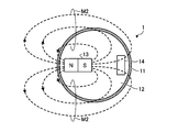
- FIG. 1 is a diagram schematically showing a capsule medical device together with a cross-sectional shape of a container of the capsule medical device according to the first embodiment.
- FIG. 2 is a cross-sectional view of the capsule medical device and the storage container when the FF line in FIG. 1 is taken as a cut surface.
- FIG. 3 is a cross-sectional view of the capsule medical device shown in FIG.
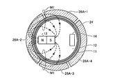
- FIG. 4 is a cross-sectional view of a storage container according to Modification 1 of Embodiment 1 and a capsule medical device stored in the storage container.
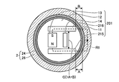
- FIG. 5 is a cross-sectional view of the storage container according to Embodiment 2 and the capsule medical device stored in the storage container.
- FIG. 6 is a cross-sectional view of the capsule medical device shown in FIG. FIG.
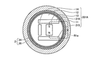
- FIG. 7 is a cross-sectional view of a storage container according to Modification 1 of Embodiment 2 and a capsule medical device stored in the storage container.
- FIG. 8 is a cross-sectional view of the capsule medical device shown in FIG.
- FIG. 9 is a cross-sectional view of a capsule medical device according to the second modification of the second embodiment.
- FIG. 10 is a cross-sectional view of a capsule medical device according to the third modification of the second embodiment.
- FIG. 11 is a cross-sectional view of another capsule medical device according to the third modification of the second embodiment.
- FIG. 12 is a cross-sectional view of a capsule medical device according to the fourth modification of the second embodiment.
- 13 is a cross-sectional view of a capsule medical device and a storage container according to Modification 4 of Embodiment 2 when the GG line in FIG. 12 is taken as a cut surface.
- FIG. 1 is a diagram schematically illustrating a capsule medical device together with a cross-sectional shape of a container of a capsule medical device according to a first embodiment of the present invention.
- the capsule medical device 1 is a swallowable capsule medical device that is introduced into the body cavity of a subject.
- the capsule medical device 1 includes an electronic component that realizes the function of the capsule medical device 1, a battery, a magnetic switch described later, and the like.
- the capsule medical device 1 is controlled to start and stop the power supply according to the switching operation of the magnetic switch.
- the storage container 2 includes a cylindrical portion 22, a base portion 21 connected to the cylindrical portion 22, a bottomed (bottom surface 25) hole 23 provided in the base portion 21, and a side surface 24 of the hole 23.
- the capsule medical device 1 is accommodated in a state where one end in the longitudinal direction of the capsule medical device 1 is fitted to the side surface 24. In this state, the storage container 2 is accommodated in an exterior container (not shown), and is sealed by closing the opening of the exterior container with a sterilization sheet.
- a cylindrical magnetic body 26 (first magnetic body) is disposed on the side surface 24 of the hole 23, and the magnetic body 26 surrounds the entire outer periphery of the side surface 24.
- the magnetic body 26 Since one end in the longitudinal direction of the capsule medical device 1 is fitted into the side surface 24 of the hole 23, when the capsule medical device 1 is stored in the storage container 2, the magnetic body 26 is used as the capsule medical device. It arrange
- the magnetic body 26 is a ferromagnetic body.
- FIG. 2 is a cross-sectional view of the capsule medical device 1 and the storage container 2 taken along the line FF in FIG.
- the capsule medical device 1 has a configuration in which a magnet 13 that is a permanent magnet and a magnetic switch 14 are provided on a substrate 12 in a capsule housing 11.
- the magnetic switch 14 is disposed in the vicinity of the magnet 13.
- the magnetic switch 14 is, for example, a reed switch, in which a part of two magnetic leads are overlapped and sealed in a glass tube together with an inert gas.
- the reed switch has a function to open the circuit by the elasticity of the lead when the magnetic field with constant strength is applied from the outside in the axial direction of the lead and the magnetized leads come in contact with each other to close the circuit.
- the magnetic switch 14 is turned on when a magnetic flux with a constant strength is applied, and turned off when the magnetic flux with a constant strength disappears. In other words, the connection of the terminal of the magnetic switch 14 is switched on or off according to the change in magnetic flux by the magnet 13 disposed in the vicinity.
- the power supply of the capsule medical device 1 is activated when the magnetic switch 14 is turned on and stopped when the magnetic switch 14 is turned off.
- the storage container 2 has the cylindrical magnetic body 26 arranged on the outer periphery of the side surface 24 of the hole 23 as described above.
- the magnetic body 26 is disposed in the vicinity of the magnetic switch 14 so as to surround the entire circumference of the capsule medical device 1 in the short direction.
- the magnetic body 26 since the magnetic body 26 has a cylindrical shape, it is arranged rotationally symmetrically with respect to the outer periphery in the short direction of the capsule medical device 1.
- the magnetic body 26 has a magnetic permeability higher than that of the magnetic switch 14.
- the magnetic flux M ⁇ b> 1 generated by the magnet 13 passes through the magnetic body 26 of the storage container 2 having a higher permeability than the magnetic switch 14. Focused on.
- a magnetic circuit in which most of the magnetic flux M1 by the magnet 13 passes through the magnetic body 26 is formed. Therefore, when the capsule medical device 1 is stored in the storage container 2, the magnetic switch 14 is not turned on since the magnetic switch 14 does not pass the magnetic flux by the magnet 13 so that the magnetic switch 14 can be kept on. The power source of the capsule medical device 1 is stopped.
- FIG. 3 is a cross-sectional view of the capsule medical device 1 when detached from the storage container 2 shown in FIG.
- the cut surface of the capsule medical device 1 in FIG. 3 is the same as the cut surface of the capsule medical device 1 in FIG.
- the magnetic body 26 that focuses the magnetic flux is separated from the vicinity of the capsule medical device 1 as shown in FIG. Therefore, a part of the magnetic flux M ⁇ b> 2 by the magnet 13 passes through the magnetic switch 14 near the magnet 13.
- a magnetic flux with a certain strength is applied to the magnetic switch 14, so that the magnetic switch 14 is turned on and the power source of the capsule medical device 1 is activated.
- the magnet 13 and the magnetic switch 14 are disposed close to each other in the capsule medical device 1, so that in the case of the capsule medical device 1 alone, the magnetic flux generated by the magnet 13 is efficiently used.
- the magnetic switch 14 can be turned on, and the power source of the capsule medical device 1 can be activated. Therefore, according to the first embodiment, since the use efficiency of the magnetic flux by the magnet 13 is increased, the capsule medical device 1 is influenced by an external magnetic field regardless of the magnetic force of the magnet 13 and the sensitivity of the magnetic switch 14.
- the power source of the capsule medical device 1 can be activated without any problems.
- Embodiment 1 when the capsule medical device 1 is stored in the storage container 2, the cylindrical magnetic body 26 surrounds the entire circumference of the outer periphery in the short direction of the capsule medical device 1. Be placed. In this case, most of the magnetic flux generated by the magnet 13 is focused not on the magnetic switch 14 but on the magnetic body 26. Therefore, the magnetic switch 14 is reliably turned off and the power supply of the capsule medical device 1 is also stopped.
- the capsule medical device 1 is stored in the storage container 2 and the capsule medical device removed from the storage container 2.
- the path through which the magnetic flux by the magnet 13 passes is switched between the path through the magnetic body 26 and the path through the magnetic switch 14, thereby turning the magnetic switch 14 on and off. I have control. Therefore, simply by storing the capsule medical device 1 in the storage container 2, the magnetic switch 14 can be turned off to stop the power supply of the capsule medical device 1.
- the power supply of the capsule medical device 1 can be activated by turning on the switch 14.
- the power supply of the capsule medical device 1 is activated and Stop can be controlled reliably and easily.
- the magnetic body 26 is disposed rotationally symmetrically with respect to the outer periphery in the short direction of the capsule medical device 1 stored in the storage container 2, regardless of the orientation of the stored capsule medical device 1,
- the magnetic flux generated by the magnet 13 can be focused on the magnetic body 26 to prevent the magnetic flux from passing to the magnetic switch 14. Therefore, the magnetic switch 14 of the capsule medical device 1 can be reliably turned off and the power supply of the capsule medical device 1 can be stopped regardless of the orientation in which the capsule medical device 1 is fitted into the hole 23 of the storage container 2.
- the capsule-type medical device 1 can be easily stored in the storage container 2 because the capsule-type medical device 1 can be fitted into the hole 23 of the storage container 2 without worrying about the orientation of the capsule-type medical device 1.
- FIG. 4 is a cross-sectional view of the storage container according to the first modification of the first embodiment and the capsule medical device 1 stored in the storage container. 4 shows the storage container according to the first modification of the first embodiment at the same cutting plane as that of the storage container and the capsule medical device in FIG. 2, and the capsule medical device 1 stored in the storage container. It is sectional drawing which cut
- the magnetic body provided in the storage container when the magnetic body provided in the storage container is disposed so as to surround at least a part of the outer periphery in the short direction of the capsule medical device 1 during storage, the magnetic flux of the magnet 13 is focused on the magnetic body. Therefore, the magnetic body does not necessarily have to be integrated, such as the first magnetic body 26A-1, the second magnetic body 26A-2, the second magnetic body 26A-3, and the fourth magnetic body 26A-4. In addition, it is possible to configure with a plurality of members.
- FIG. 5 is a cross-sectional view of the storage container according to Embodiment 2 and the capsule medical device stored in the storage container.
- FIG. 5 is a cross-sectional view of the storage container according to the second embodiment and the capsule medical device stored in the storage container taken along the cut surface at the same position as the storage surface of the storage container and the capsule medical device in FIG.
- It is. 6 is a cross-sectional view of the capsule medical device when removed from the storage container 2 shown in FIG.
- the cut surface of the capsule medical device 201 in FIG. 6 is the same as the cut surface of the capsule medical device 201 in FIG.
- the capsule medical device 201 is further provided with a pair of capsule-side magnetic bodies 215 and 216 (second magnetic bodies) on the substrate 12. It has a configuration.
- the pair of capsule-side magnetic bodies 215 and 216 are rod-shaped or plate-shaped, and are arranged opposite to each other in the vicinity of both poles of the magnet 13.
- the capsule side magnetic bodies 215 and 216 are ferromagnetic bodies. Of the both ends of the capsule-side magnetic bodies 215 and 216, one end is close to both poles of the magnet 13, and the other end is close to the housing 11.
- the end portions of the capsule-side magnetic bodies 215 and 216 on the housing 11 side are close to the magnetic body 26 when the capsule medical device 201 is stored in the storage container 2.
- the magnetic permeability of the capsule-side magnetic bodies 215 and 216 is higher than the magnetic permeability of the magnetic switch 14.
- the magnetic switch 14 is disposed between a pair of capsule-side magnetic bodies 215 and 216 that face each other. 5 and 6, the magnet 13 is located near the center in the capsule medical device 201, and the magnetic switch 14 is located on the housing 11 side.
- the magnetic flux generated by the magnet 13 is changed from the N pole of the magnet 13 to the capsule side magnetic body 215 and the magnetic body of the storage container 2. 26 and the capsule-side magnetic body 216, and passes through a closed path R1 (first path) that reaches the south pole of the magnet 13. That is, the magnetic circuit indicated by the path R1 is generated. In this case, since the magnetic flux from the magnet 13 does not pass through the magnetic switch 14, the magnetic switch 14 is turned off and the power supply of the capsule medical device 201 is also stopped.
- the magnetic body 26 disappears as shown in FIG. 6, so that the magnetic flux generated by the magnet 13 is increased from the N pole of the magnet 13 to the capsule side magnetic body 215, It passes through a closed path R2 (second path) that reaches the south pole of the magnet 13 via the magnetic switch 14 and the capsule-side magnetic body 216. That is, the magnetic circuit indicated by the path R2 is generated.
- the magnetic switch 14 since a magnetic flux with a certain strength by the magnet 13 is applied to the magnetic switch 14, the magnetic switch 14 is turned on and the power source of the capsule medical device 201 is activated.
- the capsule medical device 201 a material having a magnetic permeability higher than that of the magnetic switch 14 is selected as the capsule-side magnetic bodies 215 and 216. For this reason, in the case of the capsule medical device 201 alone, a magnetic flux sufficient to keep the magnetic switch 14 in the on state among the magnetic flux generated by the magnet 13 is guided to the capsule-side magnetic body 215 and is contained in the magnetic switch 14. And is guided from the magnetic switch 14 to the capsule-side magnetic body 216. Accordingly, in the case of the capsule medical device 201 alone, the magnetic circuit of the path R2 passing through the capsule side magnetic body 215, the magnetic switch 14, and the capsule side magnetic body 216 is surely formed.
- the magnetic switch 14 in the case of the capsule medical device 201 alone, the magnetic switch 14 can be turned on by the magnetic flux of the magnet 13 more efficiently than in the first embodiment.
- the power source of the medical device 1 can be reliably activated regardless of the external magnetic field.
- the total distance between the capsule-side magnetic bodies 215 and 216 and the magnetic body 26 is smaller than the total distance between the capsule-side magnetic bodies 215 and 216 and the magnetic switch 14.
- Each member is arranged as described above.
- the magnetic switch 14 is obtained by sealing two magnetic leads in a glass tube, it is regarded as almost air.
- the total amount (A + B) of the distance A between the capsule-side magnetic body 215 and the magnetic body 26 and the distance B between the capsule-side magnetic body 216 and the magnetic body 26 in the path R1 is:
- Each member is arranged to be smaller than the distance C between the capsule side magnetic body 215 and the capsule side magnetic body 216 in R2.
- the magnetic flux is focused on the path R1 having a small total distance between the members, and passes through the capsule side magnetic body 215, the magnetic body 26, and the capsule side magnetic body 216.
- the magnetic circuit of the path R1 is reliably formed regardless of the external magnetic field. Therefore, when the capsule medical device 201 is housed, no magnetic flux passes through the magnetic switch 14, so that the magnetic switch 14 can be reliably turned off, and accordingly, the power source of the capsule medical device 201 can be reliably stopped.
- the power supply operation of the capsule medical device 201 can be controlled more efficiently and reliably without being affected by the external magnetic field as compared with the first embodiment.
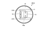
- FIG. 7 is a cross-sectional view of a storage container according to Modification 1 of Embodiment 2 and a capsule medical device stored in the storage container.
- FIG. 8 is a cross-sectional view of the capsule medical device when removed from the storage container shown in FIG. 7.
- the positions of the magnet 13 and the magnetic switch 14 in the capsule medical device 201 may be interchanged as in the capsule medical device 201A according to the first modification of the second embodiment shown in FIGS. Also in this case, when the capsule medical device 201A is stored in the storage container 2, the magnetic flux generated by the magnet 13 passes through the closed path R1a (first path) (see FIG. 7) that does not pass through the magnetic switch 14.
- the power supply of the capsule medical device 201A is surely stopped. Further, in the case of the capsule medical device 201A alone, the magnetic flux generated by the magnet 13 passes through the closed path R2a (second path) (see FIG. 8) via the magnetic switch 14, so that the capsule medical device 201A The power supply starts reliably.
- FIG. 9 is a cross-sectional view of a capsule medical device according to the second modification of the second embodiment.
- the capsule side magnetic bodies 215B and 216B are provided with projections 217B and 218B that project toward the magnetic switch 14, respectively.
- the magnetic flux M3 generated by the magnet 13 may be focused on the magnetic switch 14 positioned between the protrusion 218B and the capsule medical device 201B.
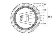
- FIG. 10 is a cross-sectional view of a capsule medical device according to the third modification of the second embodiment.
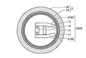
- FIG. 11 is a cross-sectional view of another capsule medical device according to the third modification of the second embodiment.
- the capsule-side magnetic bodies 215C and 216C do not have to face each other in parallel.
- the capsule side magnetic body 215C, the magnetic body 26, and the capsule side magnetic body 216C are removed from the N pole of the magnet 13 when the capsule medical device 201C is stored in the storage container 2. This is because it is sufficient to form a magnetic circuit that reaches the south pole of the magnet 13 via the via.
- the capsule side magnetic body may be bent like the capsule side magnetic bodies 215D and 216D of the capsule medical device 201D shown in FIG.
- FIG. 12 is a cross-sectional view of a capsule medical device according to the fourth modification of the second embodiment.
- 13 is a cross-sectional view of a capsule medical device and a storage container according to Modification 4 of Embodiment 2 when the GG line in FIG. 12 is taken as a cut surface.
- the capsule-side magnetic bodies 215E and 216E may be bent in the longitudinal direction of the capsule medical device 201E. As shown in FIGS. 12 and 13, the capsule-side magnetic bodies 215E and 216E are bent in the longitudinal direction of the capsule medical device 201E at the position P1, and are bent so as to be parallel to the substrate 12 at the position P1. As described above, even when the capsule-side magnetic bodies 215E and 216E are bent in the longitudinal direction of the capsule-type medical device 201E, the capsule-side magnetic material 215E and 216E can be encapsulated from the N pole of the magnet 13 when stored in the storage container 2.
- the power supply of the capsule medical device 201E can be stopped. Furthermore, when the capsule-side magnetic bodies 215E and 216E have the shapes shown in FIGS. 12 and 13, other components can be mounted above the magnet 13 or below the magnetic switch 14.
- the pair of capsule-side magnetic bodies are magnets from the N pole of the magnet 13 via one capsule-side magnetic body, the magnetic body 26, and the other capsule-side magnetic body when stored in the storage container 2 of the capsule medical device.
- the magnetic circuit may be bent in any direction as long as the magnetic circuit reaching the 13th S pole can be formed.
- the magnetic switch 14 performs a switching operation so that the power source of the capsule medical device 1 is activated when the capsule medical device 1 is detached from the storage container 2. For this reason, the magnetic switch 14 is turned off when a magnetic flux having a certain strength is applied when the capsule medical devices 1, 201, 201A to 201E are used alone, and the capsule medical devices 1, 201, 201A to 201E are stored in the storage container 2.
- the magnetic switch 14 is turned on when the magnetic flux applied to the magnetic switch 14 disappears, and the power source of the capsule medical devices 1, 201, 201A to 201E is activated when the magnetic switch 14 is turned off, and the magnetic switch 14 is turned on. Then, it may operate to stop.
- capsule medical devices 1, 201, 201A to 201E are capsule-type medical devices that are swallowed into the body of a subject, and for example, acquire in-vivo images.
Landscapes
- Health & Medical Sciences (AREA)
- Life Sciences & Earth Sciences (AREA)
- Surgery (AREA)
- Nuclear Medicine, Radiotherapy & Molecular Imaging (AREA)
- Biomedical Technology (AREA)
- Optics & Photonics (AREA)
- Pathology (AREA)
- Radiology & Medical Imaging (AREA)
- Biophysics (AREA)
- Engineering & Computer Science (AREA)
- Physics & Mathematics (AREA)
- Heart & Thoracic Surgery (AREA)
- Medical Informatics (AREA)
- Molecular Biology (AREA)
- Animal Behavior & Ethology (AREA)
- General Health & Medical Sciences (AREA)
- Public Health (AREA)
- Veterinary Medicine (AREA)
- Endoscopes (AREA)
Abstract
磁石の磁力や磁気スイッチの感度によらず、電源の起動及び停止を確実に制御できるカプセル型医療装置及びカプセル型医療装置の収納容器を提供すること。本発明は、磁石13と、磁石13の近傍に配置され、磁石13による磁束の変化に応じて端子の接続が切り替わる磁気スイッチ14とを有するカプセル型医療装置1と、カプセル型医療装置1を収納する収納容器であって、磁気スイッチ14の近傍にカプセル型医療装置1の短手方向の外周を取り囲むように配置される磁性体26を有する収納容器2と、に関する。
Description
本発明は、被検体内部に導入されるカプセル型医療装置及びカプセル型医療装置の収納容器に関するものである。
従来、検査、治療または処置が可能な飲み込み型のカプセル型医療装置が知られている。カプセル型医療装置の一つであるカプセル型内視鏡は、患者等の被検体の消化管内に導入可能な大きさに形成されたカプセル形状の筐体内に、イメージセンサ、制御部品、通信部品、バッテリ及び電源スイッチ等を備える。カプセル型内視鏡は、電源が起動した後に、被検体の口から飲み込まれ、消化管内等を蠕動運動等によって移動しながら、被検体内部を順次撮像して画像信号を生成し、生成した画像信号を体外の受信装置に順次無線送信する。カプセル型内視鏡が無線送信した体内画像は、受信装置を介してワークステーションに取り込まれ、順次表示される。
ここで、カプセル型医療装置は、被検体内に導入されるものであるため、カプセル型医療装置の外装にスイッチを設けて電源の起動及び停止を制御することができない。このため、カプセル型医療装置は、外部からの作用によって動作するリードスイッチ(磁気スイッチ)を内部に設けて電源の起動及び停止を制御している。例えば、カプセル型医療装置の内部に、電源が常時起動となる組み合わせで磁気スイッチとバイアス磁石とを設け、バイアス磁石とは逆の極性の向きとなるようにパッケージ内に永久磁石を配置し、パッケージへのカプセル型医療装置収納時には、カプセル型医療装置のバイアス磁石の磁界を無効化して磁気スイッチをオフすることによって電源を停止するカプセル型内視鏡キットが提案されている(例えば、特許文献1参照)。
磁石による磁束の磁束密度は、空気中では、距離の3乗に反比例して減衰する。特許文献1に記載の構成では、パッケージに配置される永久磁石とカプセル型医療装置の内部に設けられる磁気スイッチとの間には、少なくともカプセル型筐体及びパッケージ本体が介在するため、その分永久磁石と磁気スイッチとの距離が離れてしまう。これに応じて磁気スイッチに作用する磁束密度も減衰するため、特許文献1に記載の構成では、電源の起動及び停止を確実に制御するために、磁力の大きい永久磁石、或いは、高い感度を有する磁気スイッチを採用せざるを得ないという問題があった。
本発明は、上記に鑑みてなされたものであって、磁石の磁力や磁気スイッチの感度によらず、電源の起動及び停止を確実に制御できるカプセル型医療装置及びカプセル型医療装置の収納容器を提供することを目的とする。
上述した課題を解決し、目的を達成するために、本発明にかかるカプセル型医療装置は、磁石と、前記磁石の近傍に配置され、前記磁石による磁束の変化に応じて端子の接続が切り替わる磁気スイッチとを有するカプセル型医療装置と、前記カプセル型医療装置を収納する収納容器であって、前記磁気スイッチの近傍に前記カプセル型医療装置の短手方向の外周の少なくとも一部を取り囲むように配置される第1の磁性体を有する収納容器と、を備えたことを特徴とする。
また、本発明にかかるカプセル型医療装置は、前記カプセル型医療装置は、前記磁石の両極のそれぞれの近傍に互いに対向配置された一対の第2の磁性体をさらに有し、前記磁気スイッチは、前記対向配置された一対の第2の磁性体の間に配置されることを特徴とする。
また、本発明にかかるカプセル型医療装置は、前記磁石と一方の前記第2の磁性体と前記第1の磁性体と他方の前記第2の磁性体とを経由する第1の経路における部材間の距離の総量は、前記磁石と一方の前記第2の磁性体と前記磁気スイッチと他方の前記第2の磁性体とを経由する第2の経路における部材間の距離の総量よりも小さいことを特徴とする。
また、本発明にかかるカプセル型医療装置は、前記第2の磁性体は、前記磁気スイッチに向けて突起した突起部を有することを特徴とする。
また、本発明にかかるカプセル型医療装置は、前記第2の磁性体は、棒状或いは板状であることを特徴とする。
また、本発明にかかるカプセル型医療装置は、前記第2の磁性体は、屈曲形状を有することを特徴とする。
また、本発明にかかるカプセル型医療装置は、磁石と、前記磁石の両極のそれぞれの近傍に互いに対向配置された一対の磁性体と、前記磁石による磁束の変化に応じて端子の接続が切り替わる磁気スイッチであって、前記磁石の近傍であり、かつ、前記対向配置された一対の磁性体の間に配置される磁気スイッチと、を備えたことを特徴とする。
また、本発明にかかるカプセル型医療装置の収納容器は、磁石と、該磁石の近傍に配置されて該磁石による磁束の変化に応じて端子の接続が切り替わる磁気スイッチとを内部に備えたカプセル型医療装置の収納容器であって、前記カプセル型医療装置が収納された場合に、前記磁気スイッチの近傍に前記カプセル型医療装置の短手方向の外周の少なくとも一部を取り囲むように配置される磁性体を備えたことを特徴とする。
本発明によれば、カプセル型医療装置の磁石の近傍に磁気スイッチが配置されるため、カプセル型医療装置単体の場合には、磁石による磁束で効率よく磁気スイッチの端子接続を切り替えることができ、カプセル型医療装置の収納容器への収納時には、カプセル型医療装置の短手方向の外周の一部が第1の磁性体によって取り囲まれるため、カプセル型医療装置の磁石による磁束を、磁気スイッチではなく第1の磁性体に集束させることができることから、磁石の磁力や磁気スイッチの感度によらず、カプセル型医療装置の電源の起動及び停止を確実に制御できる。
以下、図面を参照して、本発明にかかるカプセル型医療装置及びカプセル型医療装置の収納容器の好適な実施の形態を詳細に説明する。この実施の形態によって本発明が限定されるものではない。
(実施の形態1)
図1は、本発明の実施の形態1にかかるカプセル型医療装置の収容容器の断面形状とともに、カプセル型医療装置を模式的に示した図である。
図1は、本発明の実施の形態1にかかるカプセル型医療装置の収容容器の断面形状とともに、カプセル型医療装置を模式的に示した図である。
カプセル型医療装置1は、被検体の体腔内に導入される飲み込み型のカプセル型医療装置である。カプセル型医療装置1は、カプセル型医療装置1の機能を実現する電子部品、電池、後述する磁気スイッチなどを有する。カプセル型医療装置1は、磁気スイッチのスイッチ動作に応じて電源の起動及び停止が制御される。
収納容器2は、円筒部22と、円筒部22と繋がるベース部21と、ベース部21に設けられた有底(底面25)の穴23と、穴23の側面24とから構成されており、側面24にカプセル型医療装置1の長手方向の一方の端が嵌装された状態で、カプセル型医療装置1を収納する。この状態で、収納容器2は、外装容器(不図示)内に収容され、外装容器の開口が滅菌シートで閉塞されることによって密閉される。収納容器2には、穴23の側面24に筒状の磁性体26(第1の磁性体)が配置され、磁性体26で側面24の外周の全周を取り囲む。穴23の側面24にカプセル型医療装置1の長手方向の一方の端が嵌装されるため、収納容器2にカプセル型医療装置1が収納されている場合に、磁性体26は、カプセル型医療装置1の短手方向(径方向)の外周の全周を取り囲むように配置される。磁性体26は、強磁性体である。
図2は、図1のF-F線を切断面としたときのカプセル型医療装置1及び収納容器2の断面図である。図2に示すように、カプセル型医療装置1は、カプセル型の筐体11内の基板12上に、永久磁石である磁石13と磁気スイッチ14とが設けられた構成を有する。
磁気スイッチ14は、磁石13の近傍に配置される。磁気スイッチ14は、たとえば、リードスイッチであり、2枚の磁性体リードの一部をオーバーラップさせ、不活性ガスとともにガラス管に封入したものである。リードスイッチは、リードの軸方向に外部から一定強度の磁界が加えられると磁化されたリードが互いに接触して回路を閉ざし、この一定強度の磁界が消去されるとリードの弾性により回路を開く機能を有する。具体的には、磁気スイッチ14は、一定強度の磁束が加わるとオンし、一定強度の磁束がなくなるとオフする。言い換えると、磁気スイッチ14は、近傍に配置される磁石13による磁束の変化に応じて端子の接続がオンまたはオフに切り替わる。カプセル型医療装置1の電源は、磁気スイッチ14がオンとなると起動し、磁気スイッチ14がオフとなると停止する。
収納容器2は、前述したように穴23の側面24の外周に配置された筒状の磁性体26を有する。収納容器2にカプセル型医療装置1が収納された場合、磁性体26は、磁気スイッチ14の近傍に、カプセル型医療装置1の短手方向の外周の全周を取り囲むように配置される。図2の例では、磁性体26は、筒状であるため、カプセル型医療装置1の短手方向の外周に対して回転対称に配置する。磁性体26の透磁率は、磁気スイッチ14の透磁率よりも高い。
図2のように、カプセル型医療装置1が収納容器2に収納される場合には、磁石13による磁束M1は、磁気スイッチ14よりも透磁率が高い収納容器2の磁性体26を経由するように集束される。言い換えると、カプセル型医療装置1が収納容器2に収納される場合には、磁石13による磁束M1のほとんどが磁性体26を通る磁気回路が形成される。したがって、カプセル型医療装置1が収納容器2に収納される場合には、磁気スイッチ14には、磁石13による磁束が通らずオンを維持できる程度の磁束が加わらないため、磁気スイッチ14はオフとなり、カプセル型医療装置1の電源は停止する。
図3は、図2に示す収納容器2から取り外された場合のカプセル型医療装置1の断面図である。図3におけるカプセル型医療装置1の切断面は、図2におけるカプセル型医療装置1の切断面と同一である。カプセル型医療装置1が収納容器2から取り外された場合には、図3に示すように、磁束を集束する磁性体26はカプセル型医療装置1近傍から離間する。したがって、磁石13による磁束M2の一部は、磁石13近傍の磁気スイッチ14を通る。言い換えると、カプセル型医療装置1を収納容器2から取り外した場合には、磁気スイッチ14に一定強度の磁束が加わるため、磁気スイッチ14はオンとなり、カプセル型医療装置1の電源は起動する。
このように、実施の形態1では、カプセル型医療装置1内に磁石13と磁気スイッチ14とを近接して配置するため、カプセル型医療装置1単体の場合には、磁石13による磁束で効率よく磁気スイッチ14をオンさせることができ、カプセル型医療装置1の電源を起動させることができる。したがって、実施の形態1によれば、磁石13による磁束の利用効率が上がるため、磁石13の磁力や磁気スイッチ14の感度によらず、カプセル型医療装置1単体時において、外部磁界の影響を受けることなくカプセル型医療装置1の電源を起動させることができる。
さらに、実施の形態1では、収納容器2にカプセル型医療装置1が収納される場合には、筒状の磁性体26がカプセル型医療装置1の短手方向の外周の全周を取り囲むように配置される。この場合における磁石13による磁束のほとんどは、磁気スイッチ14ではなく、磁性体26に集束されるため、磁気スイッチ14は確実にオフになり、カプセル型医療装置1の電源も停止する。
すなわち、実施の形態1では、収納容器2に筒状の磁性体26を配置することによって、カプセル型医療装置1が収納容器2に収納された場合と、収納容器2から取り外されたカプセル型医療装置1単体での場合とで、磁石13による磁束が通る経路を、磁性体26を経由する経路と、磁気スイッチ14を経由する経路との間で切り替えることで、磁気スイッチ14のオン及びオフを制御している。したがって、カプセル型医療装置1を収納容器2に収納するだけで、磁気スイッチ14をオフしてカプセル型医療装置1の電源も停止でき、カプセル型医療装置1を収納容器2から取り外すだけで、磁気スイッチ14をオンしてカプセル型医療装置1の電源を起動させることができる。このように、実施の形態1によれば、カプセル型医療装置1内に磁力の小さい磁石13や感度の低い磁気スイッチ14を採用した場合であっても、カプセル型医療装置1の電源の起動及び停止を確実かつ容易に制御できる。
また、磁性体26は、収納容器2に収納されたカプセル型医療装置1の短手方向の外周に対して回転対称に配置されるため、収納されるカプセル型医療装置1の向きによらず、磁石13による磁束を磁性体26に集束させて磁気スイッチ14への磁束通過を阻止できる。したがって、カプセル型医療装置1を収納容器2の穴23に対してどの向きに嵌め込んでも、確実にカプセル型医療装置1の磁気スイッチ14をオフし、カプセル型医療装置1の電源を停止できる。このため、実施の形態1によれば、カプセル型医療装置1の向きを気にせず収納容器2の穴23に嵌め込めばよいため、カプセル型医療装置1の収納容器2への収納処理も容易化できる。
(実施の形態1の変形例1)
図4は、実施の形態1の変形例1に係る収納容器と、該収納容器に収納されたカプセル型医療装置1の断面図である。図4は、図2における収納容器及びカプセル型医療装置の切断面と同じ位置の切断面で実施の形態1の変形例1に係る収納容器と、該収納容器に収納されたカプセル型医療装置1を切断した断面図である。
図4は、実施の形態1の変形例1に係る収納容器と、該収納容器に収納されたカプセル型医療装置1の断面図である。図4は、図2における収納容器及びカプセル型医療装置の切断面と同じ位置の切断面で実施の形態1の変形例1に係る収納容器と、該収納容器に収納されたカプセル型医療装置1を切断した断面図である。
図4に示すように、収納容器に設けられる磁性体は、収納時にカプセル型医療装置1の短手方向の外周の少なくとも一部を取り囲むように配置すれば、磁石13の磁束を磁性体に集束させることができるため、磁性体は必ずしも一体である必要はなく、第1磁性体26A-1、第2磁性体26A-2、第2磁性体26A-3及び第4磁性体26A-4のように、複数の部材で構成することも可能である。
(実施の形態2)
次に、実施の形態2について説明する。図5は、実施の形態2に係る収納容器と、該収納容器に収納されたカプセル型医療装置の断面図である。図5は、図2における収納容器及びカプセル型医療装置の切断面と同じ位置の切断面で実施の形態2に係る収納容器と、該収納容器に収納されたカプセル型医療装置を切断した断面図である。図6は、図5に示す収納容器2から取り外された場合のカプセル型医療装置の断面図である。図6におけるカプセル型医療装置201の切断面は、図5におけるカプセル型医療装置201の切断面と同一である。
次に、実施の形態2について説明する。図5は、実施の形態2に係る収納容器と、該収納容器に収納されたカプセル型医療装置の断面図である。図5は、図2における収納容器及びカプセル型医療装置の切断面と同じ位置の切断面で実施の形態2に係る収納容器と、該収納容器に収納されたカプセル型医療装置を切断した断面図である。図6は、図5に示す収納容器2から取り外された場合のカプセル型医療装置の断面図である。図6におけるカプセル型医療装置201の切断面は、図5におけるカプセル型医療装置201の切断面と同一である。
図5及び図6に示すように、実施の形態2に係るカプセル型医療装置201は、基板12上に、さらに、一対のカプセル側磁性体215,216(第2の磁性体)が設けられた構成を有する。一対のカプセル側磁性体215,216は、棒状或いは板状であり、磁石13の両極の近傍に、互いに対向配置される。このカプセル側磁性体215,216は、強磁性体である。カプセル側磁性体215,216の両端のうち、一端は、それぞれ磁石13の両極に近接し、他端は、筐体11に近接する。言い換えると、カプセル側磁性体215,216の筐体11側の端部は、カプセル型医療装置201の収納容器2への収納時においては磁性体26に近接する。カプセル側磁性体215,216の透磁率は、磁気スイッチ14の透磁率よりも高い。磁気スイッチ14は、対向配置する一対のカプセル側磁性体215,216の間に配置する。図5,6の例では、カプセル型医療装置201内の中央近傍に磁石13が位置し、筐体11側に磁気スイッチ14が位置する。
図5に示すように、カプセル型医療装置201が収納容器2に収納されている場合には、磁石13による磁束は、磁石13のN極から、カプセル側磁性体215、収納容器2の磁性体26及びカプセル側磁性体216を経由して磁石13のS極に到達する閉じた経路R1(第1の経路)を通る。すなわち、経路R1で示される磁気回路が生成される。この場合には、磁気スイッチ14に磁石13による磁束が通らないため、磁気スイッチ14はオフになり、カプセル型医療装置201の電源も停止する。
カプセル型医療装置201が収納容器2から取り外された場合には、図6に示すように、磁性体26がなくなるため、磁石13による磁束は、磁石13のN極から、カプセル側磁性体215、磁気スイッチ14及びカプセル側磁性体216を経由して磁石13のS極に到達する閉じた経路R2(第2の経路)を通る。すなわち、経路R2で示される磁気回路が生成される。この場合には、磁石13による一定強度の磁束が磁気スイッチ14に加わるため、磁気スイッチ14はオンになり、カプセル型医療装置201の電源は起動する。
ここで、カプセル型医療装置201においては、カプセル側磁性体215,216として、磁気スイッチ14の透磁率よりも高い透磁率を有する材料を選択する。このため、カプセル型医療装置201単体の場合には、磁石13による磁束のうち磁気スイッチ14のオン状態を維持させるのに十分な磁束が、カプセル側磁性体215に導かれて磁気スイッチ14の中を通り、磁気スイッチ14からカプセル側磁性体216に誘導される。これによって、カプセル型医療装置201単体の場合には、カプセル側磁性体215、磁気スイッチ14及びカプセル側磁性体216を経由する経路R2の磁気回路が確実に形成される。したがって、実施の形態2によれば、カプセル型医療装置201単体の場合には、実施の形態1と比して、さらに効率よく、磁石13による磁束で磁気スイッチ14をオンさせることができ、カプセル型医療装置1の電源を、外部磁界によらず確実に起動させることができる。
そして、実施の形態2では、カプセル側磁性体215,216と磁性体26との間の距離の総量が、カプセル側磁性体215,216と磁気スイッチ14との間の距離の総量よりも小さくなるように各部材が配置される。ここで、磁気スイッチ14は、前述したように、ガラス管に2枚の磁性体リードを封入したものであるため、ほぼ空気としてみなす。実施の形態2では、経路R1におけるカプセル側磁性体215と磁性体26との間の距離Aと、カプセル側磁性体216と磁性体26との間の距離Bとの総量(A+B)は、経路R2におけるカプセル側磁性体215とカプセル側磁性体216との間の距離Cよりも小さくなるように各部材が配置される。これによって、カプセル型医療装置201の収納容器2への収納時には、部材間の距離の総量が小さい経路R1に磁束が集束し、カプセル側磁性体215、磁性体26及びカプセル側磁性体216を経由する経路R1の磁気回路が、外部磁界によらず確実に形成される。したがって、カプセル型医療装置201の収納時には、磁気スイッチ14には磁束が通らないため、磁気スイッチ14を確実にオフでき、これに伴い、カプセル型医療装置201の電源を確実に停止できる。
このように、実施の形態2では、実施の形態1と比して、外部磁界の影響を受けることなく、さらに効率的かつ確実に、カプセル型医療装置201の電源動作を制御することができる。
(実施の形態2の変形例1)
図7は、実施の形態2の変形例1に係る収納容器と、該収納容器に収納されたカプセル型医療装置の断面図である。図8は、図7に示す収納容器から取り外された場合のカプセル型医療装置の断面図である。カプセル型医療装置201における磁石13と磁気スイッチ14との位置を、図7及び図8に示す実施の形態2の変形例1に係るカプセル型医療装置201Aのように入れ替えてもよい。この場合も、カプセル型医療装置201Aが収納容器2に収納されている場合には、磁石13による磁束は、磁気スイッチ14を経由しない閉じた経路R1a(第1の経路)(図7参照)を通るため、カプセル型医療装置201Aの電源は確実に停止する。また、カプセル型医療装置201A単体の場合には、磁石13による磁束は、磁気スイッチ14を経由する閉じた経路R2a(第2の経路)(図8参照)を通るため、カプセル型医療装置201Aの電源は確実に起動する。
図7は、実施の形態2の変形例1に係る収納容器と、該収納容器に収納されたカプセル型医療装置の断面図である。図8は、図7に示す収納容器から取り外された場合のカプセル型医療装置の断面図である。カプセル型医療装置201における磁石13と磁気スイッチ14との位置を、図7及び図8に示す実施の形態2の変形例1に係るカプセル型医療装置201Aのように入れ替えてもよい。この場合も、カプセル型医療装置201Aが収納容器2に収納されている場合には、磁石13による磁束は、磁気スイッチ14を経由しない閉じた経路R1a(第1の経路)(図7参照)を通るため、カプセル型医療装置201Aの電源は確実に停止する。また、カプセル型医療装置201A単体の場合には、磁石13による磁束は、磁気スイッチ14を経由する閉じた経路R2a(第2の経路)(図8参照)を通るため、カプセル型医療装置201Aの電源は確実に起動する。
(実施の形態2の変形例2)
図9は、実施の形態2の変形例2に係るカプセル型医療装置の断面図である。図9のカプセル型医療装置201Bに示すように、カプセル側磁性体215B,216Bにそれぞれ、磁気スイッチ14に向けて突起した突起部217B,218Bを設け、カプセル型医療装置201B単体時には、突起部217Bと突起部218Bとの間に位置する磁気スイッチ14に、磁石13による磁束M3を集束させて、さらにカプセル型医療装置201Bの起動をより確実にしてもよい。
図9は、実施の形態2の変形例2に係るカプセル型医療装置の断面図である。図9のカプセル型医療装置201Bに示すように、カプセル側磁性体215B,216Bにそれぞれ、磁気スイッチ14に向けて突起した突起部217B,218Bを設け、カプセル型医療装置201B単体時には、突起部217Bと突起部218Bとの間に位置する磁気スイッチ14に、磁石13による磁束M3を集束させて、さらにカプセル型医療装置201Bの起動をより確実にしてもよい。
(実施の形態2の変形例3)
図10は、実施の形態2の変形例3に係るカプセル型医療装置の断面図である。また、図11は、実施の形態2の変形例3に係る他のカプセル型医療装置の断面図である。図10に示すカプセル型医療装置201Cのように、カプセル側磁性体215C,216Cは、平行に対向せずともよい。カプセル型医療装置201Cの電源を停止するには、カプセル型医療装置201Cの収納容器2への収納時に、磁石13のN極から、カプセル側磁性体215C、磁性体26及びカプセル側磁性体216Cを経由して磁石13のS極に到達する磁気回路を形成できれば足りるためである。同様の理由で、図11に示すカプセル型医療装置201Dのカプセル側磁性体215D,216Dのように、カプセル側磁性体は、屈曲形状であってもよい。
図10は、実施の形態2の変形例3に係るカプセル型医療装置の断面図である。また、図11は、実施の形態2の変形例3に係る他のカプセル型医療装置の断面図である。図10に示すカプセル型医療装置201Cのように、カプセル側磁性体215C,216Cは、平行に対向せずともよい。カプセル型医療装置201Cの電源を停止するには、カプセル型医療装置201Cの収納容器2への収納時に、磁石13のN極から、カプセル側磁性体215C、磁性体26及びカプセル側磁性体216Cを経由して磁石13のS極に到達する磁気回路を形成できれば足りるためである。同様の理由で、図11に示すカプセル型医療装置201Dのカプセル側磁性体215D,216Dのように、カプセル側磁性体は、屈曲形状であってもよい。
(実施の形態2の変形例4)
図12は、実施の形態2の変形例4に係るカプセル型医療装置の断面図である。図13は、図12のG-G線を切断面としたときの実施の形態2の変形例4に係るカプセル型医療装置及び収納容器の断面図である。
図12は、実施の形態2の変形例4に係るカプセル型医療装置の断面図である。図13は、図12のG-G線を切断面としたときの実施の形態2の変形例4に係るカプセル型医療装置及び収納容器の断面図である。
図12および図13に示すカプセル型医療装置201Eのように、カプセル側磁性体215E,216Eがカプセル型医療装置201Eの長手方向に屈曲していてもよい。図12および図13に示すように、カプセル側磁性体215E,216Eは、位置P1で、カプセル型医療装置201Eの長手方向に屈曲し、位置P1で、基板12と平行となるように屈曲する。このようにカプセル側磁性体215E,216Eが、カプセル型医療装置201Eの長手方向に屈曲する場合も、カプセル型医療装置201Eの収納容器2への収納時に、磁石13のN極から、カプセル側磁性体215E、磁性体26及びカプセル側磁性体216Eを経由して磁石13のS極に到達する磁気回路を形成できるため、カプセル型医療装置201Eの電源の停止が可能となる。さらに、カプセル側磁性体215E,216Eが図12及び図13に示す形状である場合には、磁石13の上方や磁気スイッチ14の下方に他の部品を搭載することができる。一対のカプセル側磁性体は、カプセル型医療装置の収納容器2への収納時に、磁石13のN極から、一方のカプセル側磁性体、磁性体26及び他方のカプセル側磁性体を経由して磁石13のS極に到達する磁気回路を形成できれば、いずれの方向に屈曲していてもよい。
なお、実施の形態1,2では、カプセル型医療装置1,201,201A~201Eが収納容器2に収納されている場合にはカプセル型医療装置1の電源が停止し、カプセル型医療装置1が収納容器2から取り外された時にはカプセル型医療装置1の電源が起動するように、磁気スイッチ14がスイッチ動作すれば足りる。このため、磁気スイッチ14は、カプセル型医療装置1,201,201A~201E単体時において一定強度の磁束が加わるとオフし、カプセル型医療装置1,201,201A~201Eの収納容器2への収納時において、磁気スイッチ14に加えられた磁束がなくなるとオンする構成であって、カプセル型医療装置1,201,201A~201Eの電源は、磁気スイッチ14がオフすると起動し、磁気スイッチ14がオンすると停止するように動作してもよい。
また、上述した本発明の実施の形態1,2にかかるカプセル型医療装置1,201,201A~201Eは、被検体の体内に飲み込まれるカプセル型の医療装置であり、たとえば、体内画像を取得するカプセル型内視鏡、生体内のpH情報を体内情報として計測するカプセル型pH計測装置、生体内の温度情報を体内情報として計測するカプセル型温度計測装置、生体内に薬剤を散布または注射する機能を備えたカプセル型薬剤投与装置、或いは、生体内の物質(体組織等)を採取するカプセル型採取装置である。
1,201,201A~201E カプセル型医療装置
2 収納容器
11 筐体
12 基板
13 磁石
14 磁気スイッチ
21 ベース部
22 円筒部
23 穴
24 側面
25 底面
26 磁性体(第1の磁性体)
215,215B~215E,216,216B~216E カプセル側磁性体(第2の磁性体)
217B,218B 突起部
2 収納容器
11 筐体
12 基板
13 磁石
14 磁気スイッチ
21 ベース部
22 円筒部
23 穴
24 側面
25 底面
26 磁性体(第1の磁性体)
215,215B~215E,216,216B~216E カプセル側磁性体(第2の磁性体)
217B,218B 突起部
Claims (8)
- 磁石と、前記磁石の近傍に配置され、前記磁石による磁束の変化に応じて端子の接続が切り替わる磁気スイッチとを有するカプセル型医療装置と、
前記カプセル型医療装置を収納する収納容器であって、前記磁気スイッチの近傍に前記カプセル型医療装置の短手方向の外周の少なくとも一部を取り囲むように配置される第1の磁性体を有する収納容器と、
を備えたことを特徴とするカプセル型医療装置。 - 前記カプセル型医療装置は、前記磁石の両極のそれぞれの近傍に互いに対向配置された一対の第2の磁性体をさらに有し、
前記磁気スイッチは、前記対向配置された一対の第2の磁性体の間に配置されることを特徴とする請求項1に記載のカプセル型医療装置。 - 前記磁石と一方の前記第2の磁性体と前記第1の磁性体と他方の前記第2の磁性体とを経由する第1の経路における部材間の距離の総量は、前記磁石と一方の前記第2の磁性体と前記磁気スイッチと他方の前記第2の磁性体とを経由する第2の経路における部材間の距離の総量よりも小さいことを特徴とする請求項2に記載のカプセル型医療装置。
- 前記第2の磁性体は、前記磁気スイッチに向けて突起した突起部を有することを特徴とする請求項2または3に記載のカプセル型医療装置。
- 前記第2の磁性体は、棒状或いは板状であることを特徴とする請求項2~4のいずれか一つに記載のカプセル型医療装置。
- 前記第2の磁性体は、屈曲形状を有することを特徴とする請求項2~4のいずれか一つに記載のカプセル型医療装置。
- 磁石と、
前記磁石の両極のそれぞれの近傍に互いに対向配置された一対の磁性体と、
前記磁石による磁束の変化に応じて端子の接続が切り替わる磁気スイッチであって、前記磁石の近傍であり、かつ、前記対向配置された一対の磁性体の間に配置される磁気スイッチと、
を備えたことを特徴とするカプセル型医療装置。 - 磁石と、該磁石の近傍に配置されて該磁石による磁束の変化に応じて端子の接続が切り替わる磁気スイッチとを内部に備えたカプセル型医療装置の収納容器であって、
前記カプセル型医療装置が収納された場合に、前記磁気スイッチの近傍に前記カプセル型医療装置の短手方向の外周の少なくとも一部を取り囲むように配置される磁性体を備えたことを特徴とするカプセル型医療装置の収納容器。
Applications Claiming Priority (2)
| Application Number | Priority Date | Filing Date | Title |
|---|---|---|---|
| JP2015089308A JP2018093887A (ja) | 2015-04-24 | 2015-04-24 | カプセル型医療装置及びカプセル型医療装置の収納容器 |
| JP2015-089308 | 2015-04-24 |
Publications (1)
| Publication Number | Publication Date |
|---|---|
| WO2016170899A1 true WO2016170899A1 (ja) | 2016-10-27 |
Family
ID=57144401
Family Applications (1)
| Application Number | Title | Priority Date | Filing Date |
|---|---|---|---|
| PCT/JP2016/059229 Ceased WO2016170899A1 (ja) | 2015-04-24 | 2016-03-23 | カプセル型医療装置及びカプセル型医療装置の収納容器 |
Country Status (2)
| Country | Link |
|---|---|
| JP (1) | JP2018093887A (ja) |
| WO (1) | WO2016170899A1 (ja) |
Citations (3)
| Publication number | Priority date | Publication date | Assignee | Title |
|---|---|---|---|---|
| JP2003210393A (ja) * | 2002-01-22 | 2003-07-29 | Olympus Optical Co Ltd | カプセル型医療装置 |
| JP2003210395A (ja) * | 2002-01-22 | 2003-07-29 | Olympus Optical Co Ltd | カプセル型医療装置 |
| WO2007074883A1 (ja) * | 2005-12-27 | 2007-07-05 | Olympus Medical Systems Corp. | 医療装置用収納装置と、廃棄装置と、医療装置の使用方法 |
-
2015
- 2015-04-24 JP JP2015089308A patent/JP2018093887A/ja active Pending
-
2016
- 2016-03-23 WO PCT/JP2016/059229 patent/WO2016170899A1/ja not_active Ceased
Patent Citations (3)
| Publication number | Priority date | Publication date | Assignee | Title |
|---|---|---|---|---|
| JP2003210393A (ja) * | 2002-01-22 | 2003-07-29 | Olympus Optical Co Ltd | カプセル型医療装置 |
| JP2003210395A (ja) * | 2002-01-22 | 2003-07-29 | Olympus Optical Co Ltd | カプセル型医療装置 |
| WO2007074883A1 (ja) * | 2005-12-27 | 2007-07-05 | Olympus Medical Systems Corp. | 医療装置用収納装置と、廃棄装置と、医療装置の使用方法 |
Also Published As
| Publication number | Publication date |
|---|---|
| JP2018093887A (ja) | 2018-06-21 |
Similar Documents
| Publication | Publication Date | Title |
|---|---|---|
| CN101346093B (zh) | 医疗装置用容纳装置、报废装置 | |
| US8961400B2 (en) | Capsule-medical-device dedicated power source starter | |
| US8480562B2 (en) | Capsule medical apparatus | |
| CN109497917B (zh) | 消化道采样胶囊 | |
| JP2003210395A (ja) | カプセル型医療装置 | |
| CN102512135A (zh) | 被检体内导入装置 | |
| JP2005198878A (ja) | カプセル型医療装置 | |
| WO2005063111A1 (ja) | 医療用カプセル装置 | |
| JPWO2010067765A1 (ja) | カプセル型医療装置およびその製造方法 | |
| JP2010069209A (ja) | カプセル型医療装置およびその製造方法 | |
| CN104244797A (zh) | 磁场产生装置以及胶囊型医疗装置引导系统 | |
| JP2005095433A (ja) | カプセル型医療装置収納具 | |
| JP4611033B2 (ja) | 被検体内情報取得装置の収容ケース | |
| JP2005192820A (ja) | カプセル型医療装置 | |
| CN101065047B (zh) | 胶囊型内窥镜的收纳壳体 | |
| JP4226045B2 (ja) | カプセル型医療装置 | |
| WO2016170899A1 (ja) | カプセル型医療装置及びカプセル型医療装置の収納容器 | |
| JP2009125101A (ja) | カプセル型医療機器 | |
| JP2005205072A (ja) | カプセル型医療装置 | |
| JP4632734B2 (ja) | カプセル型内視鏡用電源スターター | |
| JP4869312B2 (ja) | カプセル型医療装置 | |
| JP2006141897A (ja) | 被検体内情報取得装置 | |
| JP4472401B2 (ja) | 被検体内情報取得装置 | |
| JP2007185521A (ja) | カプセル型医療装置 | |
| JP2010240144A (ja) | 体内観察システム |
Legal Events
| Date | Code | Title | Description |
|---|---|---|---|
| 121 | Ep: the epo has been informed by wipo that ep was designated in this application |
Ref document number: 16782921 Country of ref document: EP Kind code of ref document: A1 |
|
| NENP | Non-entry into the national phase |
Ref country code: DE |
|
| 122 | Ep: pct application non-entry in european phase |
Ref document number: 16782921 Country of ref document: EP Kind code of ref document: A1 |
|
| NENP | Non-entry into the national phase |
Ref country code: JP |