WO2016170880A1 - 送風装置 - Google Patents
送風装置 Download PDFInfo
- Publication number
- WO2016170880A1 WO2016170880A1 PCT/JP2016/058599 JP2016058599W WO2016170880A1 WO 2016170880 A1 WO2016170880 A1 WO 2016170880A1 JP 2016058599 W JP2016058599 W JP 2016058599W WO 2016170880 A1 WO2016170880 A1 WO 2016170880A1
- Authority
- WO
- WIPO (PCT)
- Prior art keywords
- induction heating
- fan
- air
- blades
- blower
- Prior art date
- Legal status (The legal status is an assumption and is not a legal conclusion. Google has not performed a legal analysis and makes no representation as to the accuracy of the status listed.)
- Ceased
Links
Images





Classifications
-
- B—PERFORMING OPERATIONS; TRANSPORTING
- B60—VEHICLES IN GENERAL
- B60H—ARRANGEMENTS OF HEATING, COOLING, VENTILATING OR OTHER AIR-TREATING DEVICES SPECIALLY ADAPTED FOR PASSENGER OR GOODS SPACES OF VEHICLES
- B60H1/00—Heating, cooling or ventilating devices
-
- F—MECHANICAL ENGINEERING; LIGHTING; HEATING; WEAPONS; BLASTING
- F04—POSITIVE - DISPLACEMENT MACHINES FOR LIQUIDS; PUMPS FOR LIQUIDS OR ELASTIC FLUIDS
- F04D—NON-POSITIVE-DISPLACEMENT PUMPS
- F04D29/00—Details, component parts, or accessories
- F04D29/26—Rotors specially for elastic fluids
- F04D29/28—Rotors specially for elastic fluids for centrifugal or helico-centrifugal pumps for radial-flow or helico-centrifugal pumps
-
- F—MECHANICAL ENGINEERING; LIGHTING; HEATING; WEAPONS; BLASTING
- F04—POSITIVE - DISPLACEMENT MACHINES FOR LIQUIDS; PUMPS FOR LIQUIDS OR ELASTIC FLUIDS
- F04D—NON-POSITIVE-DISPLACEMENT PUMPS
- F04D29/00—Details, component parts, or accessories
- F04D29/58—Cooling; Heating; Diminishing heat transfer
-
- F—MECHANICAL ENGINEERING; LIGHTING; HEATING; WEAPONS; BLASTING
- F24—HEATING; RANGES; VENTILATING
- F24F—AIR-CONDITIONING; AIR-HUMIDIFICATION; VENTILATION; USE OF AIR CURRENTS FOR SCREENING
- F24F1/00—Room units for air-conditioning, e.g. separate or self-contained units or units receiving primary air from a central station
-
- F—MECHANICAL ENGINEERING; LIGHTING; HEATING; WEAPONS; BLASTING
- F24—HEATING; RANGES; VENTILATING
- F24H—FLUID HEATERS, e.g. WATER OR AIR HEATERS, HAVING HEAT-GENERATING MEANS, e.g. HEAT PUMPS, IN GENERAL
- F24H3/00—Air heaters
- F24H3/02—Air heaters with forced circulation
- F24H3/04—Air heaters with forced circulation the air being in direct contact with the heating medium, e.g. electric heating element
-
- H—ELECTRICITY
- H05—ELECTRIC TECHNIQUES NOT OTHERWISE PROVIDED FOR
- H05B—ELECTRIC HEATING; ELECTRIC LIGHT SOURCES NOT OTHERWISE PROVIDED FOR; CIRCUIT ARRANGEMENTS FOR ELECTRIC LIGHT SOURCES, IN GENERAL
- H05B6/00—Heating by electric, magnetic or electromagnetic fields
- H05B6/02—Induction heating
- H05B6/10—Induction heating apparatus, other than furnaces, for specific applications
- H05B6/14—Tools, e.g. nozzles, rollers, calenders
-
- H—ELECTRICITY
- H05—ELECTRIC TECHNIQUES NOT OTHERWISE PROVIDED FOR
- H05B—ELECTRIC HEATING; ELECTRIC LIGHT SOURCES NOT OTHERWISE PROVIDED FOR; CIRCUIT ARRANGEMENTS FOR ELECTRIC LIGHT SOURCES, IN GENERAL
- H05B6/00—Heating by electric, magnetic or electromagnetic fields
- H05B6/02—Induction heating
- H05B6/36—Coil arrangements
- H05B6/40—Establishing desired heat distribution, e.g. to heat particular parts of workpieces
Definitions
- the present disclosure relates to a blower that blows air.
- Patent Document 1 discloses an example in which an iron fan, an aluminum fan, and a resin fan having a conductive film provided on the surface are used as a fan of a blower.
- the material of the conductive member constituting the fan is made of a common material for the entire fan.
- an iron fan with high electrical resistivity can efficiently heat the fan by induction heating, but on the other hand, the thermal conductivity is low, so the temperature distribution tends to occur in the fan, and the fan heat is efficiently It is difficult to dissipate heat to the air.
- an aluminum fan with high thermal conductivity can efficiently dissipate the heat of the fan to the blown air, but on the other hand, since the electrical resistivity is low, there is little heat generation and efficient by induction heating. It is difficult to heat the fan.
- This disclosure aims to provide a blower capable of achieving both efficiency of heating a fan by induction heating and efficiency of heat radiation from the fan to the air.
- the present disclosure is directed to a blower device including a fan that sucks and blows air by rotating, an electric motor that rotationally drives the fan, and an induction heating coil that heats the fan by induction heating.
- the fan of the blower device includes a plurality of blades arranged at intervals so that air can flow, and a plurality of blades connected to each other and a rotational driving force from the electric motor. Is connected to the plurality of blades.
- wing is comprised with the material whose heat conductivity is higher than a connection part.
- the connection part is comprised with the material whose integrated value of a magnetic permeability and an electrical resistivity is higher than a some blade
- the connecting portion connecting the plurality of blades is efficiently heated by induction heating, and the heat of the connecting portion heated by induction heating is efficiently transferred to the air side through each blade having high thermal conductivity. It is possible to dissipate heat well.
- blower of the present disclosure it is possible to achieve both the efficiency of heating the fan by induction heating and the efficiency of heat dissipation from the fan to the air.
- FIG. 5 is a VV cross-sectional view of FIG. 1. It is explanatory drawing for demonstrating the action
- This embodiment demonstrates the example which applied the air blower 2 of this indication to the air blower of the vehicle air conditioner 1 which air-conditions a vehicle interior.
- the vehicle air conditioner 1 includes an air conditioning unit 10 and a blower 2 as main components.
- the arrow which shows the top and the bottom shown in FIG. 1 has shown the up-down direction at the time of mounting the vehicle air conditioner 1 in a vehicle. The same applies to other drawings.
- the air conditioning unit 10 is disposed in a lower part of an instrument panel (that is, an instrument panel) in the passenger compartment.
- the air conditioning unit 10 includes an evaporator 13 and a heater core 14 in an air conditioning case 11 that forms an outer shell thereof.
- the air conditioning case 11 constitutes a ventilation path for blown air to be blown into the vehicle interior.
- the air conditioning case 11 of the present embodiment is formed of a resin (for example, polypropylene) having a certain degree of elasticity and excellent in strength.
- an inside / outside air switching box 12 for switching and introducing outside air (ie, outside air) and inside air (ie, inside air) is arranged.
- the inside / outside air switching box 12 is formed with an outside air introduction port 121 for introducing outside air and an inside air introduction port 122 for introducing inside air.
- inside / outside air switching box 12 is arranged with inside / outside air switching door 123 that adjusts the opening area of each inlet 121, 122 and changes the ratio between the amount of outside air introduced and the amount of inside air introduced. Yes.
- the inside / outside air switching door 123 is rotatably disposed between the outside air introduction port 121 and the inside air introduction port 122.
- the inside / outside air switching door 123 is driven by an actuator (not shown).
- the evaporator 13 which comprises the cooling part which cools the ventilation air to the vehicle interior is arrange
- the evaporator 13 is a heat exchanger that absorbs the latent heat of evaporation of the low-temperature refrigerant circulating inside from the blown air and cools the blown air.
- the evaporator 13 constitutes a vapor compression refrigeration cycle together with a compressor, a condenser, and a decompression mechanism (not shown).
- the heater core 14 is a heat exchanger that heats blown air using engine cooling water (not shown) as a heat source.
- the heater core 14 constitutes a heating unit that heats the blown air.
- An air mix door 18 is rotatably disposed between the evaporator 13 and the heater core 14.
- the air mix door 18 is driven by an actuator (not shown) to adjust the ratio of the air flowing through the hot air passage 16 and the air flowing through the cold air bypass passage 17 to adjust the temperature of the blown air to be blown into the vehicle interior. It is a member to do.
- a blower 20 constituting the blower 2 is disposed on the downstream side of the hot air passage 16 and the cold air bypass passage 17 in the air flow.
- the blower 20 is a device that generates an air flow that blows into the passenger compartment inside the air conditioning case 11. Details of the blower 2 will be described later.
- An air conditioning duct 19 is connected to the air discharge side of the blower 20.
- the air-conditioning duct 19 is a member that guides the blown air to a blowing portion (not shown) that opens into the vehicle interior and blows air into the vehicle interior.
- the blowout part is provided with a face blowout opening that blows air toward the upper body side of the occupant, a foot blowout opening that blows air toward the lower body side of the occupant, and a defroster blowout opening that blows air toward the window glass on the front of the vehicle ing.
- the air conditioning duct 19 is provided with a mode switching door (not shown) for setting the air blowing mode from each outlet. The mode switching door is driven by an actuator (not shown).
- the blower 2 includes a blower 20, a power transmission circuit 50, and a control circuit 100.
- the blower 20 includes a blower case 21, a fan 22 accommodated in the blower case 21, an electric motor 25 that drives the fan 22, and the like.
- the blower case 21 constitutes a part of the air conditioning case 11.
- the blower case 21 of the present embodiment is formed of a resin (for example, polypropylene) having a certain degree of elasticity and excellent in strength.
- a suction port 211 that opens on one end side in the direction of the axis CL of the rotating shaft 252 in the electric motor 25 (that is, the axial direction of the fan 22), and a discharge that discharges air sucked through the suction port 211.
- An outlet 213 is formed.
- the fan 22 sucks in air on the downstream side of the air flow in the hot air passage 16 and the cold air bypass passage 17 via the suction port 211 and discharges it from the discharge port 213.
- the fan 22 of the present embodiment is configured by a centrifugal fan that blows air sucked from the direction of the axis CL (that is, the axial direction of the fan 22) radially outward.
- the fan 22 is rotationally driven by the electric motor 25.
- the fan 22 includes a plurality of blades 221, a main plate 223, and a shroud 224.
- the plurality of blades 221 are annularly arranged around the axis CL of the rotation shaft 252 in the electric motor 25 so that air can flow between the blades 221.
- Each blade 221 is connected to the shroud 224 at the end on the suction port 211 side (that is, one end side in the axial direction) in the direction of the axis CL. Further, each blade 221 is connected to the main plate 223 at the end opposite to the suction port 211 in the direction of the axis CL (that is, the other end side in the axial direction).
- each blade 221 is provided with a first engagement portion 221 a that engages with an engagement hole 224 a formed in the shroud 224 at one end facing the shroud 224.
- Each blade 221 has a second engagement portion 221b that engages with an engagement hole 223c formed in the main plate 223 at the other end facing the main plate 223.
- the main plate 223 is formed of a member having a conical shape whose central portion is recessed toward the suction port 211 in the direction of the axis CL.
- the main plate 223 has a plate portion 223 a to which the other end side in the direction of the axis CL of each blade 221 is connected, and a boss portion 223 b to be connected to the rotating shaft 252 of the electric motor 25.
- the main plate 223 of the present embodiment constitutes a connecting portion that connects the other end side of each blade 221 in the axial direction and transmits the rotational driving force from the electric motor 25 to each blade 221.
- FIG. 4 is a top view of the main plate 223 viewed from the axial direction of the fan 22.
- the plate portion 223a is formed with first and second groove portions 225 and 226 for accommodating first and second induction heating coils 51 and 52, which will be described later, on the back side of the portion where the blades 221 are coupled. Yes. Specifically, the first and second groove portions 225 and 226 are formed on the back side of the portion of the plate portion 223a where the engagement hole 223c is formed. As shown in the cross-sectional view of FIG. 5, each of the groove portions 225 and 226 is formed in an annular shape centering on the boss portion 223 b.
- the boss portion 223 b is a fitting portion that is formed at the center portion of the main plate 223 and is fitted to the rotating shaft 252 of the electric motor 25.
- the boss portion 223b and the rotation shaft 252 of this embodiment are prevented from rotating by a non-rotating pin (not shown). Therefore, when the rotating shaft 252 rotates, the main plate 223 rotates in conjunction with the rotation of the rotating shaft 252.
- the shroud 224 is a member having a disk shape in which an opening having a size corresponding to the suction port 211 is formed at the center.
- the shroud 224 is a member that connects one end side of each blade 221 in the axial direction.
- a plurality of engagement holes 224 a corresponding to the first engagement portions 221 a of the blades 221 are formed in the shroud 224.
- Each blade 221, main plate 223, and shroud 224 of the present embodiment are made of a metal material.
- the fan 22 according to the present embodiment is integrated by brazing joint in a state where the engagement portions 221a and 221b of the blades 221 are engaged with the engagement holes 223c of the main plate 223 and the engagement holes 224a of the shroud 224. Configured. The details of the material constituting each component 221, 223, 224 of the fan 22 will be described later.
- the electric motor 25 includes a motor main body 251, a metal (for example, iron) rotating shaft 252, a support 253 connected to the blower case 21, and a drive circuit (not shown).
- the motor main body 251 is a drive unit that rotationally drives the fan 22 via the rotary shaft 252.
- the motor body 251 is supported by the blower case 21 via the support 253.
- the motor main body 251 is accommodated in a space formed between the blower case 21 and the main plate 223.
- the motor main body 251 includes a core fixed to the support 253, a rotor disposed outside the core and fixed to the rotary shaft 252, a magnet fixed to the inner peripheral side of the rotor, and the rotary shaft 252.
- the power transmission circuit 50 includes first and second induction heating coils 51 and 52 for induction heating the fan 22, a resonance circuit 53, and a power supply circuit 54.
- the first and second induction heating coils 51 and 52 are arranged so as to face the main plate 223 of the fan 22.
- the induction heating coils 51 and 52 of the present embodiment are disposed on the other end side in the axial direction of the fan 22 (that is, the side opposite to the suction port 211) and on the opposite side of each blade 221 in the main plate 223. .
- the 1st, 2nd induction heating coils 51 and 52 are comprised by the coil of the annular
- the induction heating coils 51 and 52 of the present embodiment are accommodated in the groove portions 225 and 226 formed in the plate portion 223a of the main plate 223 in a non-contact manner with the groove portions 225 and 226, respectively.
- a predetermined gap is provided between the fan 22 and the induction heating coils 51 and 52 of the present embodiment, and the fan 22 and the induction heating coils 51 and 52 are not in contact with each other. Moreover, although not shown in figure, each induction heating coil 51 and 52 is being fixed to the ventilation case 21 side. For this reason, the fan 22 can be rotated without contacting the induction heating coils 51 and 52.
- the resonance circuit 53 and the power supply circuit 54 constitute an AC supply unit that supplies an AC current having a predetermined frequency (for example, 25 kHz) to the induction heating coils 51 and 52.
- the power supply circuit 54 is a circuit constituting an AC signal generation source.
- the resonance circuit 53 is adjusted so as to perform magnetic field resonance in a state where the induction heating coils 51 and 52 are arranged to face the fan 22.
- a single resonance circuit 53 is connected to each induction heating coil 51, 52.
- a magnetic field is generated around each induction heating coil 51, 52 by supplying an alternating current from the power supply circuit 54 to each induction heating coil 51, 52.
- an eddy current that is, an induced current
- the main plate 223 of the fan 22 generates Joule heat corresponding to the square of the electric resistance of the main plate 223 ⁇ eddy current and generates heat.
- the heating power P of the fan 22 (for example, the main plate 223) by this induction heating is proportional to the skin resistance Rs of the main plate 223 and also to the square of the magnetic flux H as shown in the following formula F1.
- the skin resistance Rs of the main plate 223 is proportional to the square root of the frequency f of the current I flowing through the induction heating coils 51 and 52 and the electrical resistivity ⁇ , the magnetic permeability ⁇ of the main plate 223, as in the following formula F2.
- the magnetic flux H is proportional to the number of turns (that is, the number of turns) N and the current I of each induction heating coil 51, 52 as in the following formula F3.
- the fan 22 is configured such that the main plate 223 generates heat by energizing the induction heating coils 51 and 52, and the heat of the main plate 223 is transmitted to the blown air via the blades 221.
- the main plate 223 constitutes a heat generating portion
- each blade 221 constitutes a heat radiating portion that radiates heat of the main plate 223 to the blown air.
- each blade 221 constituting the heat radiating portion in the fan 22 is made of a material having a high thermal conductivity ⁇ .
- each blade 221 is made of aluminum, and the main plate 223 is made of iron.
- Aluminum has a thermal conductivity ⁇ of about 237 [W / mK], which is much higher than the thermal conductivity of iron ( ⁇ 80 [W / mK]).
- the heat transfer coefficient of each material of this embodiment has described the value in 300K.
- Iron has an electrical resistivity of about 0.17 [ ⁇ m] and a relative permeability of about 2000, and its integrated value ( ⁇ ⁇ ⁇ 34) is the electrical resistivity of aluminum ( ⁇ 0.027 [ ⁇ m]) and relative permeability ( ⁇ 1), which is an extremely large value ( ⁇ ⁇ ⁇ 0.027).
- Each blade 221 may be made of a material having a thermal conductivity ⁇ higher than that of the main plate 223.
- Each blade 221 is made of, for example, a material whose main component is aluminum having a high thermal conductivity ⁇ (for example, aluminum alloy), copper ( ⁇ 398 [W / mK], ⁇ 0.017 [ ⁇ m], ⁇ You may comprise by the material which has 1) as a main component.
- Each blade 221 may be made of a material other than a metal material as long as it has a higher thermal conductivity ⁇ than the main plate 223.
- the main plate 223 may be made of a material having a higher integrated value of electrical resistivity ⁇ and permeability ⁇ than each blade 221, for example, iron having a higher integrated value of electrical resistivity ⁇ and permeability ⁇ . You may comprise with the material (for example, stainless steel) as a main component.
- the main plate 223 may be made of a material other than a metal material as long as the integrated value of the electrical resistivity ⁇ and the magnetic permeability ⁇ is higher than that of each blade 221.
- the shroud 224 of the fan 22 of the present embodiment is made of aluminum that is relatively lightweight. Since the shroud 224 is desirably lightweight, the shroud 224 may be made of a material such as a resin.
- the control circuit 100 includes a microcomputer including a storage unit such as a CPU, a ROM, and a RAM, and its peripheral circuits.
- the control circuit 100 is a circuit that performs various arithmetic processes based on the control program stored in the storage unit, and controls the operation of the motor drive circuit connected to the output side, the power supply circuit 54, and the like.
- the control circuit 100 constitutes an energization control unit that controls the operation of the power supply circuit 54 and the like in response to a request from the air conditioning unit 10 during operation of the blower 20.
- the storage unit of the control circuit 100 is configured by a non-transitional tangible storage medium.
- the operation of the air blower 2 of the present embodiment according to the above configuration will be described.
- the rotating shaft 252 of the electric motor 25 rotates.
- the fan 22 rotates in conjunction with the rotation of the rotation shaft 252.
- the air sucked from the suction port 211 of the blower case 21 along the axis line CL is blown out toward the radially outer side of the fan 22.
- the air blown out from the fan 22 is blown out into the passenger compartment through the discharge port 213 of the blower case 21 and the air conditioning duct 19.
- each blade 221 of the fan 22 is made of a material having a higher thermal conductivity than the main plate 223, and the main plate 223 is an integration of magnetic permeability and electrical resistivity than each blade 221. Consists of materials with high values.
- the main plate 223 connecting the blades 221 of the fan 22 is efficiently heated by induction heating, and the heat of the main plate 223 heated by induction heating is transferred to the air via the blades 221 having high thermal conductivity. It is possible to efficiently dissipate heat to the side.
- the heat transfer from the blades 221 to the air side in the fan 22 is caused by the rotation of the blades 221 compared to the case where the heat moves from the flat plate fixed so as not to move to the air side.
- the boundary layer formed on the surface of each blade 221 is thinned by the force. For this reason, in the fan 22, compared with the case where heat moves from the above-described flat plate to the air side, the heat easily moves from each blade 221 to the air side.
- each blade 221 since there are a plurality of blades 221, it is possible to secure a sufficient area in contact with the air in each blade 221, and to heat the air with a sufficient amount of heat transfer. Furthermore, since each blade 221 is made of a material having high thermal conductivity, the temperature of each blade 221 becomes nearly uniform over the entire region of the blade 221, and heat can be efficiently transferred to the air side.
- the air blower 2 of the present embodiment it is possible to achieve both the efficiency of heating the fan 22 by induction heating and the efficiency of heat dissipation from the fan 22 to the air.
- the eddy current flowing through the main plate 223 increases as the distance between each induction heating coil 51, 52 and the main plate 223 of the fan 22 constituting the heated portion increases, so that the efficiency of induction heating increases.
- the induction heating coils 51 and 52 are arranged at positions close to the main plate 223.
- each induction heating coil 51 and 52 is arrange
- the main plate 223 is formed with grooves 225 and 226 having shapes corresponding to the induction heating coils 51 and 52, and the induction heating coils 51 are not in contact with the grooves 225 and 226 inside the grooves 225 and 226. , 52 are accommodated.
- the heated area in the main plate 223 can be sufficiently ensured.
- each induction heating coil 51, 52 can be reduced, the current flowing through the main plate 223 can be increased by the electromagnetic induction action of each induction heating coil 51, 52. Therefore, it is possible to further increase the efficiency of heating the main plate 223 by induction heating.
- the main plate 223 itself also functions as a magnetic shield that shields magnetic flux leakage caused by energization of the induction heating coils 51 and 52, so that the magnetic flux interlinking the induction heating coils 51 and 52 is around the blower 2. It can suppress affecting the equipment.
- the fan 22 is constituted by a centrifugal fan that blows out air sucked from one end side in the direction of the axis CL in the radial direction.
- the induction heating coils 51 and 52 are arranged on the other end side in the axial direction of the fan 22 and on the side opposite to the blades 221 on the main plate 223. According to this, since each induction heating coil 51 and 52 does not become a factor which disturbs the airflow produced
- the induction heating coil 51 may be one or more. The same applies to the following embodiments.
- FIG. 7 2nd Embodiment is described using FIG. 7, FIG.
- This embodiment is different from the first embodiment in that the fan 22A of the blower 20A is configured by a cross flow fan.
- description of the same or equivalent parts as in the first embodiment will be omitted or simplified.
- the blower 20 ⁇ / b> A of the present embodiment includes first and second fans 22 ⁇ / b> A and 23 ⁇ / b> A, a blower case 21 ⁇ / b> A that accommodates the fans 22 ⁇ / b> A and 23 ⁇ / b> A, and an electric motor 25.
- Each of the fans 22 ⁇ / b> A and 23 ⁇ / b> A is configured by a cross flow fan in which air flows in a direction crossing the rotation shaft 252.
- the first fan 22A has a plurality of blades 221A arranged around the rotation shaft 252 and a first end plate 261 connecting one end side of the rotation shaft 252 in each blade 221A.
- Each blade 221A is annularly arranged around the rotation shaft 252 of the electric motor 25 so that air can flow between the blades 221A.
- the first end plate 261 is connected to one end side of each blade 221 ⁇ / b> A and is connected to the rotating shaft 252 of the electric motor 25.
- the first end plate 261 is formed with a third groove portion 261a for accommodating the third induction heating coil 55 on the back side of the portion where the blades 221A are coupled.
- the second fan 23A has a plurality of blades 231A arranged around the rotation shaft 252 and a second end plate 262 that connects the other end side of the rotation shaft 252 in each blade 231A.
- Each blade 231A is annularly arranged around the rotation shaft 252 of the electric motor 25 so that air can flow between the blades 231A.
- the second end plate 262 is connected to the other end side of each blade 231A and is connected to the rotating shaft 252 of the electric motor 25.
- the second end plate 262 is formed with a fourth groove portion 262a for accommodating the fourth induction heating coil 56 on the back side of the portion where the blades 231A are coupled.
- the end plates 261 and 262 of the present embodiment connect the blades 221A and 231A and constitute the connecting portion 26 that transmits the rotational driving force from the electric motor 25 to the blades 221A and 231A.
- the fans 22A and 23A are connected by an intermediate plate 27 so as to be aligned in the direction of the rotating shaft 252, and are configured as one cylindrical body.
- the intermediate plate 27 is formed in an annular shape, and connects the blades 221A and 231A.
- the intermediate plate 27 is not connected to the rotating shaft 252 of the electric motor 25.
- a stabilizer 215 that prevents the backflow of the airflow generated by the rotation of the fan 22 is formed in the blower case 21 ⁇ / b> A between the suction port 211 ⁇ / b> A and the discharge port 213 ⁇ / b> A.
- the stabilizer 215 has a protruding shape that protrudes toward the fan 22 side.
- a vortex ie, a circulating flow
- the air sucked from the suction port 211A of the blower case 21A flows along the direction intersecting the rotation shaft 252 and blown out from the discharge port 213A.
- the blades 221A and 231A are made of a material having a higher thermal conductivity ⁇ than the end plates 261 and 262, and the end plates 261 and 262 are made to have an electrical resistivity ⁇ and a permeability higher than those of the blades 221A and 231A. It is made of a material having a high integrated value with the magnetic permeability ⁇ .
- each blade 221A, 231A is made of aluminum, and each end plate 261, 262 is made of iron.
- Each blade 221A, 231A only needs to be a material having a higher thermal conductivity ⁇ than the end plates 261, 262.
- a material mainly composed of aluminum having a high thermal conductivity ⁇ for example, an aluminum alloy
- Each end plate 261, 262 may be a material having a higher integrated value of electrical resistivity ⁇ and permeability ⁇ than each blade 221A, 231A, for example, an integrated value of electrical resistivity ⁇ and permeability ⁇ .
- You may comprise with the material (for example, stainless steel) which has iron as a main component with a high value.
- the intermediate plate 27 of each fan 22A, 23A of the present embodiment is made of aluminum that is relatively light.
- the intermediate plate 27 is preferably lightweight and may be made of a material such as resin.
- the power transmission circuit 50 includes third and fourth induction heating coils 55 and 56 that inductively heat the fans 22A and 23A, a resonance circuit 53, and a power supply circuit 54.
- the third induction heating coil 55 is disposed so as to face the first end plate 261.
- the third induction heating coil 55 of the present embodiment is disposed on the opposite side of each blade 221 ⁇ / b> A in the first end plate 261.
- the third induction heating coil 55 is formed of an annular coil corresponding to the inside of the third groove 261a formed in the first end plate 261, and the third groove 261a and the third groove 261a are formed inside the third groove 261a. It is housed in a non-contact manner.
- the fourth induction heating coil 56 is disposed so as to face the second end plate 262.
- the fourth induction heating coil 56 of the present embodiment is disposed on the opposite side of each blade 231 ⁇ / b> A in the second end plate 262.
- the fourth induction heating coil 56 is formed of an annular coil corresponding to the inside of the fourth groove portion 262a formed in the second end plate 262, and the fourth groove portion 262a and the fourth groove portion 262a are arranged inside the fourth groove portion 262a. It is housed in a non-contact manner.
- the rotating shaft 252 of the electric motor 25 rotates.
- the fans 22A and 23A rotate in conjunction with the rotation of the rotation shaft 252.
- the air sucked from the suction port 211A of the blower case 21A passes through the fans 22A and 23A in the direction intersecting the rotation shaft 252 and blows out as shown in FIG. Is done.
- the air blown out from each of the fans 22A and 23A is blown out into the passenger compartment through the discharge port 213A of the blower case 21A and the air conditioning duct.
- each blade 221A, 231A is made of a material having a higher thermal conductivity than each end plate 261, 262, and each end plate 261, 262 has a permeability higher than each blade 221A, 231A. It is made of a material with a high integrated value with electrical resistivity.
- the end plates 261 and 262 are efficiently heated by induction heating, and the heat of the end plates 261 and 262 heated by induction heating is transferred to the air via the blades 221A and 231A having high thermal conductivity. It is possible to efficiently dissipate heat to the side.
- blower device 2 of the present embodiment it is possible to achieve both the efficiency of heating the fans 22A and 23A by induction heating and the efficiency of heat radiation from the fans 22A and 23A to the air.
- the present invention is not limited to this.
- the air blower 2 is not limited to a moving body such as a vehicle, but may be applied to a stationary air conditioner used in a home or factory. Moreover, you may apply the air blower 2 not only to an air conditioner but to the apparatus which adjusts the temperature of an apparatus, for example.
- the position of the air blower 20 is not located on the air flow downstream side of the temperature adjustment device such as the evaporator 13 or the heater core 14 but on the air flow upstream side of the temperature adjustment device. Also good.
- each component of the fan 22 includes an element made of a material other than a metal material (for example, resin), the element may be connected in a separate process.
- the induction heating coils 51, 52, 55, and 56 are preferably disposed at positions closer to the connecting portion than the blades 221, 221A, and 231A, but are not limited thereto.
- a part of each induction heating coil 51, 52, 55, 56 may be arranged at a position closer to each blade 221, 221A, 231A than the connecting portion.
- each induction heating coil 51, 52, 55, 56 is preferably housed in each groove 225, 226, 261a, 262a formed in the connecting portion of the main plate 223, etc. It is not limited to.
- Each induction heating coil 51, 52, 55, 56 may be arranged at another position as long as it is a position close to the connecting portion such as the main plate 223.
- each induction heating coil 51, 52, 55, 56 may be arranged at another position as long as it is a position close to the connecting portion such as the main plate 223.
- blower 2 itself includes the resonance circuit 53 and the power supply circuit 54 has been described.
- the present invention is not limited to this.
- 52, 55, and 56 may be configured to supply an alternating current.
- first and second induction heating coils 51 and 52 are arranged at positions close to the main plate 223
- the present invention is not limited to this.
- one of the first and second induction heating coils 51 and 52 may be disposed at a position close to the main plate 223.
- a third induction heating coil may be added.
Landscapes
- Engineering & Computer Science (AREA)
- Mechanical Engineering (AREA)
- Physics & Mathematics (AREA)
- General Engineering & Computer Science (AREA)
- Thermal Sciences (AREA)
- Chemical & Material Sciences (AREA)
- Combustion & Propulsion (AREA)
- Electromagnetism (AREA)
- Structures Of Non-Positive Displacement Pumps (AREA)
- General Induction Heating (AREA)
- Air-Conditioning Room Units, And Self-Contained Units In General (AREA)
- Air-Conditioning For Vehicles (AREA)
Abstract
送風装置(2)は、回転することで空気を吸い込んで吹き出すファン(22、22A、23A)と、ファン(22、22A、23A)を回転駆動する電動機(25)と、ファン(22、22A、23A)を誘導加熱により加熱する誘導加熱コイル(51、52、55、56)と、を備える。ファン(22、22A、23A)は、空気が流通可能なように間隔をあけて配置された複数枚の羽根(221、221A、231A)、および複数枚の羽根を連結すると共に電動機(25)からの回転駆動力を複数枚の羽根(221、221A、231A)へ伝達する連結部(223、26)を有する。そして、複数枚の羽根(221、221A、231A)は、連結部(223、26)よりも熱伝導率の高い材料で構成されている。連結部(223、26)は、複数枚の羽根(221、221A、231A)よりも透磁率と電気抵抗率との積算値が高い材料で構成されている。
Description
本出願は、2015年4月20日に出願された日本出願番号2015-86024号に基づくものであって、ここにその記載内容を援用する。
本開示は、空気を送風する送風装置に関する。
従来、誘導加熱コイルに高周波数の交流電流を供給して、導電性を有するファンを加熱することで、ファンを介して送風空気を加熱する送風機が提案されている(例えば、特許文献1参照)。この特許文献1には、送風機のファンとして、鉄製ファン、アルミ製ファン、表面に導電膜が設けられた樹脂製ファンを用いる例が開示されている。なお、特許文献1では、ファンを構成する導電性部材の材質がファン全体として共通の材料で構成している。
ところで、本発明者らの検討によれば、特許文献1の如く、ファンを構成する導電性部材の材質を共通の材料で構成すると、誘導加熱によるファンの加熱の効率化、およびファンから空気への放熱の効率化を両立させることが難しいことがわかった。
例えば、電気抵抗率が高い鉄製ファンでは、誘導加熱によりファンを効率よく加熱することが可能であるが、その反面、熱伝導率が低いためにファンに温度分布が生じ易く、ファンの熱を効率よく送風空気へ放熱することが難しい。
一方、熱伝導率が高いアルミ製ファンでは、ファンの熱を効率よく送風空気へ放熱させることが可能であるが、その反面、電気抵抗率が低いために、発熱が少なく、誘導加熱により効率よくファンを加熱することが難しい。
本開示は、誘導加熱によるファンの加熱の効率化、およびファンから空気への放熱の効率化を両立可能な送風装置を提供することを目的とする。
本開示は、回転することにより空気を吸い込んで吹き出すファンと、ファンを回転駆動する電動機と、ファンを誘導加熱により加熱する誘導加熱コイルと、を備える送風装置を対象としている。
本開示の1つの観点によれば、送風装置のファンは、空気が流通可能なように間隔をあけて配置された複数枚の羽根、および複数枚の羽根を連結すると共に電動機からの回転駆動力を複数枚の羽根へ伝達する連結部を有している。そして、複数枚の羽根は、連結部よりも熱伝導率の高い材料で構成されている。また、連結部は、複数枚の羽根よりも透磁率と電気抵抗率との積算値が高い材料で構成されている。
これによれば、複数枚の羽根を連結する連結部を誘導加熱により効率よく加熱すると共に、誘導加熱により加熱された連結部の熱を、熱伝導率の高い各羽根を介して空気側へ効率よく放熱させることが可能となる。
従って、本開示の送風装置によれば、誘導加熱によるファンの加熱の効率化、およびファンから空気への放熱の効率化を両立させることが可能となる。
以下、本開示の実施形態について図面を参照して説明する。なお、以下の各実施形態において、先行する実施形態で説明した事項と同一もしくは均等である部分には、同一の参照符号を付し、その説明を省略する場合がある。また、各実施形態において、構成要素の一部だけを説明している場合、構成要素の他の部分に関しては、先行する実施形態において説明した構成要素を適用することができる。
(第1実施形態)
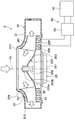
本実施形態では、本開示の送風装置2を車室内の空調を行う車両用空調装置1の送風手段に適用した例について説明する。図1に示すように、車両用空調装置1は、主たる構成要素として、空調ユニット10、および送風装置2を備える。なお、図1に示す上と下とを示す矢印は、車両用空調装置1を車両に搭載した際の上下方向を示している。このことは、他の図面においても同様である。
本実施形態では、本開示の送風装置2を車室内の空調を行う車両用空調装置1の送風手段に適用した例について説明する。図1に示すように、車両用空調装置1は、主たる構成要素として、空調ユニット10、および送風装置2を備える。なお、図1に示す上と下とを示す矢印は、車両用空調装置1を車両に搭載した際の上下方向を示している。このことは、他の図面においても同様である。
まず、空調ユニット10について説明する。空調ユニット10は、車室内の計器盤(すなわち、インストルメントパネル)の下方部に配置されている。空調ユニット10は、その外殻を形成する空調ケース11の内部に、蒸発器13、ヒータコア14を収容したものである。
空調ケース11は、車室内へ送風する送風空気の通風路を構成する。本実施形態の空調ケース11は、ある程度の弾性を有し、強度的にも優れた樹脂(例えば、ポリプロピレン)により成形されている。
空調ケース11の空気流れ最上流側には、車室外空気(すなわち、外気)と車室内空気(すなわち、内気)とを切替導入する内外気切替箱12が配置されている。内外気切替箱12には、外気を導入する外気導入口121、および内気を導入する内気導入口122が形成されている。さらに、内外気切替箱12の内部には、各導入口121、122の開口面積を調整して、外気の導入量と内気の導入量との割合を変化させる内外気切替ドア123が配置されている。
内外気切替ドア123は、外気導入口121と内気導入口122との間に回動自在に配置されている。内外気切替ドア123は、図示しないアクチュエータにより駆動される。
内外気切替箱12の空気流れ下流側には、車室内への送風空気を冷却する冷却部を構成する蒸発器13が配置されている。蒸発器13は、内部を流通する低温冷媒の蒸発潜熱を送風空気から吸熱して、送風空気を冷却する熱交換器である。蒸発器13は、図示しない圧縮機、凝縮器、減圧機構と共に蒸気圧縮式の冷凍サイクルを構成する。
蒸発器13の空気流れ下流側には、蒸発器13で冷却された空気をヒータコア14側へ流す温風通路16、および蒸発器13で冷却された空気を、ヒータコア14を迂回して流す冷風バイパス通路17が形成されている。
ヒータコア14は、図示しないエンジンの冷却水を熱源として、送風空気を加熱する熱交換器である。本実施形態では、ヒータコア14が送風空気を加熱する加熱部を構成する。
蒸発器13とヒータコア14との間には、エアミックスドア18が回動自在に配置されている。エアミックスドア18は、図示しないアクチュエータにより駆動されて、温風通路16を流通させる空気と冷風バイパス通路17を流通させる空気との割合を調整して、車室内へ送風する送風空気の温度を調整する部材である。
温風通路16、および冷風バイパス通路17の空気流れ下流側には、送風装置2を構成する送風機20が配置されている。送風機20は、空調ケース11の内部に車室内へ吹き出す空気流を発生させる機器である。送風装置2の詳細については後述する。
送風機20の空気吐出側には、空調用ダクト19が接続されている。空調用ダクト19は、車室内に開口して車室内へ空気を吹き出す図示しない吹出部へ送風空気を導く部材である。吹出部としては、図示しないが、乗員の上半身側に空気を吹き出すフェイス吹出口、乗員の下半身側に空気を吹き出すフット吹出口、車両前面の窓ガラスに向けて空気を吹き出すデフロスタ吹出口が設けられている。また、空調用ダクト19には、各吹出口からの空気の吹出モードを設定する図示しないモード切替ドアが設けられている。モード切替ドアは、図示しないアクチュエータにより駆動される。
続いて、送風装置2について説明する。送風装置2は、送風機20、送電回路50、制御回路100を備える。送風機20は、送風ケース21、送風ケース21に収容されたファン22、ファン22を駆動する電動機25等で構成されている。
送風ケース21は、空調ケース11の一部を構成している。本実施形態の送風ケース21は、ある程度の弾性を有し、強度的にも優れた樹脂(例えば、ポリプロピレン)により成形されている。
送風ケース21には、電動機25における回転軸252の軸線CLの方向(すなわち、ファン22の軸方向)の一端側に開口する吸込口211、および吸込口211を介して吸い込んだ空気を吐出する吐出口213が形成されている。
ファン22は、吸込口211を介して温風通路16および冷風バイパス通路17の空気流れ下流側の空気を吸い込み、吐出口213から吐出する。本実施形態のファン22は、軸線CLの方向(すなわち、ファン22の軸方向)から吸い込んだ空気を径方向外側に吹き出す遠心ファンで構成されている。ファン22は、電動機25によって回転駆動される。
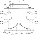
具体的には、図2、図3に示すように、ファン22は、複数枚の羽根221、主板223、およびシュラウド224を備える。複数枚の羽根221は、各羽根221の間を空気が流通可能なように、電動機25における回転軸252の軸線CLの周りに間隔をあけて環状に配置されている。
各羽根221は、軸線CLの方向における吸込口211側(すなわち、軸方向の一端側)の端部がシュラウド224に連結されている。また、各羽根221は、軸線CLの方向における吸込口211の反対側(すなわち、軸方向の他端側)の端部が主板223に連結されている。
各羽根221は、図3に示すように、シュラウド224に対向する一端部に、シュラウド224に形成された係合穴224aに係合する第1係合部221aが設けられている。また、各羽根221は、主板223に対向する他端部に、主板223に形成された係合穴223cに係合する第2係合部221bが形成されている。
主板223は、中央部が軸線CLの方向における吸込口211側へ窪んだ円錐状の形状を有する部材で構成される。主板223は、各羽根221の軸線CLの方向の他端側が連結されるプレート部223a、および電動機25の回転軸252に連結されるボス部223bを有する。本実施形態の主板223は、各羽根221の軸方向の他端側を連結すると共に、電動機25からの回転駆動力を各羽根221へ伝達する連結部を構成する。
プレート部223aには、図4に示すように、各羽根221の第2係合部221bに対応する係合穴223cが複数形成されている。図4は、ファン22の軸方向から見た主板223の上面図である。
また、プレート部223aには、各羽根221が結合される部位の背面側に、後述する第1、第2誘導加熱コイル51、52を収容する第1、第2溝部225、226が形成されている。具体的には、第1、第2溝部225、226は、プレート部223aにおける係合穴223cが形成された部位の背面側に形成されている。各溝部225、226は、図5の断面図に示すように、ボス部223bを中心とする円環形状に形成されている。
ボス部223bは、主板223の中央部に形成されて電動機25の回転軸252に嵌合する嵌合部である。本実施形態のボス部223bと回転軸252とは、図示しない回り止めピンにより回り止めされている。従って、回転軸252が回転すると、回転軸252の回転に連動して主板223が回転する。
シュラウド224は、図2、図3に示すように、中央部に吸込口211に対応する大きさの開口部が形成された円盤状の形状を有する部材である。シュラウド224は、各羽根221の軸方向の一端側を連結する部材である。シュラウド224には、各羽根221の第1係合部221aに対応する係合穴224aが複数形成されている。
本実施形態の各羽根221、主板223、およびシュラウド224は、金属材料により構成されている。本実施形態のファン22は、主板223の各係合穴223c、シュラウド224の各係合穴224aに各羽根221の各係合部221a、221bを係合させた状態で、ろう付け接合により一体に構成される。なお、ファン22の各構成要素221、223、224を構成する材料の詳細については、後述する。
電動機25は、モータ本体部251、金属製(例えば、鉄製)の回転軸252、送風ケース21に連結された支持具253、図示しない駆動回路を備える。モータ本体部251は、回転軸252を介してファン22を回転駆動する駆動手段である。
モータ本体部251は、支持具253を介して送風ケース21に支持されている。モータ本体部251は、送風ケース21と主板223との間に形成される空間に収容されている。
モータ本体部251は、図示しないが、支持具253に固定されたコア、コアの外側に配置されると共に回転軸252に固定されたロータ、ロータの内周側に固定されたマグネット、回転軸252を回転可能に支持する軸受等を有する。
電動機25は、駆動回路からモータ本体部251のコアに電力が供給されると、コアに磁束変化が生じる。これにより、ロータに固定されたマグネットを引き寄せる力が発生し、この力を受けてロータが回転軸252と共に回転する。
続いて、送電回路50は、ファン22を誘導加熱する第1、第2誘導加熱コイル51、52、共振回路53、および電源回路54を有して構成される。
第1、第2誘導加熱コイル51、52は、ファン22の主板223と対向するように配置されている。本実施形態の各誘導加熱コイル51、52は、ファン22の軸方向の他端側(すなわち、吸込口211とは反対側)であって主板223における各羽根221の反対側に配置されている。
また、第1、第2誘導加熱コイル51、52は、図5に示すように、主板223のプレート部223aに形成された各溝部225、226の内部に対応する円環状の形状のコイルで構成されている。本実施形態の各誘導加熱コイル51、52は、主板223のプレート部223aに形成された各溝部225、226の内部に各溝部225、226と非接触に収容されている。
本実施形態のファン22と各誘導加熱コイル51、52との間には、所定の間隔が設けられており、ファン22と各誘導加熱コイル51、52とが非接触となっている。また、各誘導加熱コイル51、52は、図示しないが、送風ケース21側に固定されている。このため、ファン22は、各誘導加熱コイル51、52に接触することなく回転可能となっている。
共振回路53および電源回路54は、各誘導加熱コイル51、52へ所定周波数(例えば、25kHz)の交流電流を供給する交流供給部を構成している。電源回路54は、交流信号の発生源を構成する回路である。共振回路53は、各誘導加熱コイル51、52がファン22に対向配置された状態で、磁界共鳴するように調整されている。本実施形態では、各誘導加熱コイル51、52に対して単一の共振回路53を接続している。
送電回路50では、電源回路54から交流電流が各誘導加熱コイル51、52へ供給されることで、各誘導加熱コイル51、52の周囲に磁界が発生する。この際、ファン22の主板223には、各誘導加熱コイル51、52の周囲に発生した磁界を打ち消す方向に渦電流(すなわち、誘導電流)が流れる。ファン22の主板223には、主板223の電気抵抗×渦電流の2乗に相当するジュール熱が発生して発熱する。
この誘導加熱によるファン22(例えば、主板223)の加熱電力Pは、以下の数式F1の如く、主板223の表皮抵抗Rsに比例すると共に、磁束Hの2乗に比例する。
P∝Rs×H2 ・・・(F1)
そして、主板223の表皮抵抗Rsは、以下の数式F2の如く、主板223の電気抵抗率ρ、透磁率μ、各誘導加熱コイル51、52に流れる電流Iの周波数fの平方根に比例する。
そして、主板223の表皮抵抗Rsは、以下の数式F2の如く、主板223の電気抵抗率ρ、透磁率μ、各誘導加熱コイル51、52に流れる電流Iの周波数fの平方根に比例する。
Rs∝(ρ×μ×f)1/2 ・・・(F2)
また、磁束Hは、以下の数式F3の如く、各誘導加熱コイル51、52のターン数(すなわち、巻き数)Nと電流Iに比例する。
また、磁束Hは、以下の数式F3の如く、各誘導加熱コイル51、52のターン数(すなわち、巻き数)Nと電流Iに比例する。
H∝N×I ・・・(F3)
上述の数式F1~F3によれば、加熱電力Pは、以下の数式F4で表すことができる。
上述の数式F1~F3によれば、加熱電力Pは、以下の数式F4で表すことができる。
P∝(ρ×μ×f)1/2×(N×I)2 ・・・(F4)
ここで、ファン22は、誘導加熱コイル51、52への通電により主板223が発熱し、主板223の熱を、各羽根221を介して送風空気へ伝えるように構成されている。本実施形態では、主板223が発熱部を構成し、各羽根221が主板223の熱を送風空気へ放熱する放熱部を構成する。
ここで、ファン22は、誘導加熱コイル51、52への通電により主板223が発熱し、主板223の熱を、各羽根221を介して送風空気へ伝えるように構成されている。本実施形態では、主板223が発熱部を構成し、各羽根221が主板223の熱を送風空気へ放熱する放熱部を構成する。
数式F4に示すように、誘導加熱によりファン22を効率よく加熱するためには、ファン22における発熱部を構成する主板223を電気抵抗率ρと透磁率μとの積算値(=ρ×μ)が高い材料で構成することが望ましい。
一方、ファン22から空気側へ効率よく放熱するためには、空気側に接する部材の温度を均一化させて放熱面積を拡大することが有効となる。このため、ファン22における放熱部を構成する各羽根221を熱伝導率λが高い材料で構成することが望ましい。
そこで、本実施形態では、各羽根221を主板223よりも熱伝導率λの高い材料で構成し、主板223を各羽根221よりも電気抵抗率ρと透磁率μとの積算値(=ρ×μ)の高い材料で構成している。なお、熱伝導率λ、電気抵抗率ρ、透磁率μは、温度依存性があることから、同一温度条件下で比較した際の前述の条件を満たす材料を採用することが望ましい。
具体的には、本実施形態では、各羽根221をアルミニウムで構成し、主板223を鉄で構成している。
アルミニウムは、熱伝導率λが約237[W/mK]であり、鉄の熱伝導率(λ≒80[W/mK])よりも極めて高い値となる。なお、本実施形態の各材料の熱伝達率は、300Kでの値を記載している。
また、鉄は、電気抵抗率が約0.17[μΩm]、比透磁率が約2000であり、その積算値(ρ×μ≒34)が、アルミニウムにおける電気抵抗率(ρ≒0.027[μΩm])と比透磁率(μ≒1)との積算値(ρ×μ≒0.027)よりも極めて大きい値となる。
各羽根221は、主板223よりも熱伝導率λの高い材料であればよい。各羽根221は、例えば、熱伝導率λが高いアルミニウムを主成分とする材料(例えば、アルミニウム合金)や、銅(λ≒398[W/mK]、ρ≒0.017[μΩm]、μ≒1)を主成分とする材料で構成してもよい。なお、各羽根221は、主板223よりも熱伝導率λの高い材料であれば、金属材料以外の材料で構成してもよい。
同様に、主板223は、各羽根221よりも電気抵抗率ρと透磁率μとの積算値が高い材料であればよく、例えば、電気抵抗率ρと透磁率μとの積算値が高い鉄を主成分とする材料(例えば、ステンレス)で構成してもよい。なお、主板223は、各羽根221よりも電気抵抗率ρと透磁率μとの積算値が高い材料であれば、金属材料以外の材料で構成してもよい。
本実施形態のファン22のシュラウド224は、比較的軽量となるアルミニウムで構成している。なお、シュラウド224は、軽量であることが望ましいことから、樹脂等の材料で構成してもよい。
続いて、制御回路100は、CPU、ROMやRAMといった記憶部を含むマイクロコンピュータと、その周辺回路で構成されている。制御回路100は、記憶部に記憶された制御プログラムに基づいて、各種演算処理を行い、出力側に接続されたモータ駆動回路や、電源回路54等の作動を制御する回路である。制御回路100は、送風機20の作動中に、空調ユニット10側からの要求に応じて電源回路54等の作動を制御する通電制御部を構成する。なお、制御回路100の記憶部は、非遷移的実体的記憶媒体で構成される。
次に、上記構成に係る本実施形態の送風装置2の作動を説明する。まず、駆動回路からモータ本体部251のコアに電力が供給されると、電動機25の回転軸252が回転する。そして、ファン22は、回転軸252の回転に連動して回転する。ファン22の回転により、図6に示すように、送風ケース21の吸込口211から軸線CLに沿って吸い込まれた空気が、ファン22の径方向外側に向かって吹き出される。そして、ファン22から吹き出された空気は、送風ケース21の吐出口213、および空調用ダクト19を介して車室内へ吹き出される。
この状態で、送電回路50の電源回路54から交流電流が各誘導加熱コイル51、52へ供給されると、各誘導加熱コイル51、52の周囲に磁界が発生する。この際、ファン22の主板223には、各誘導加熱コイル51、52の周囲に発生した磁界を打ち消す方向に渦電流(すなわち、誘導電流)が流れる。ファン22の主板223には、主板223の電気抵抗×渦電流の2乗に相当するジュール熱が発生して発熱する。そして、主板223の熱は、各羽根221を介して、送風ケース21に吸い込まれた空気に放熱される。これにより、ファン22に吸い込まれた空気が加熱される。ファン22で加熱された空気は、空調用ダクト19を介して車室内へ吹き出される。
以上説明した本実施形態の送風装置2は、ファン22の各羽根221を主板223よりも熱伝導率の高い材料で構成し、主板223を各羽根221よりも透磁率と電気抵抗率との積算値が高い材料で構成している。
これによれば、ファン22の各羽根221を連結する主板223を誘導加熱により効率よく加熱すると共に、誘導加熱により加熱された主板223の熱を、熱伝導率の高い各羽根221を介して空気側へ効率よく放熱させることが可能となる。
ここで、ファン22における各羽根221から空気側への熱移動は、動かないように固定された平板から空気側へ熱が移動する場合と比較して、各羽根221が回転することで生ずる遠心力により各羽根221の表面に形成される境界層が薄くなる。このため、ファン22では、前述の平板から空気側へ熱が移動する場合と比較して、各羽根221から空気側へ熱が移動し易くなる。
また、羽根221は複数枚あるので、各羽根221における空気と接する面積を充分に確保することができ、充分な伝熱量で空気を加熱することができる。さらに、各羽根221は、熱伝導率の高い材料で構成されているため、各羽根221の温度が羽根221の全域で均一に近くなり、効率よく空気側へ熱を移動させることができる。
従って、本実施形態の送風装置2によれば、誘導加熱によるファン22の加熱の効率化、およびファン22から空気への放熱の効率化を両立させることが可能となる。
ここで、各誘導加熱コイル51、52と被加熱部位を構成するファン22の主板223との距離が近いほど、主板223を流れる渦電流が増加することから、誘導加熱の効率が高くなる。
そこで、本実施形態では、各羽根221、および主板223のうち、主板223に近い位置に各誘導加熱コイル51、52を配置している。このように、各誘導加熱コイル51、52を各羽根221よりも主板223に近接する位置に配置すれば、誘導加熱による主板223の加熱のより一層の効率化を図ることができる。
また、主板223には、各誘導加熱コイル51、52に対応する形状を有する溝部225、226を形成し、当該溝部225、226の内部に当該溝部225、226と非接触に各誘導加熱コイル51、52を収容している。
これによれば、ファン22において被加熱部位を構成する主板223における各誘導加熱コイル51、52と対向する面積を大きくすることができるので、主板223における被加熱面積を充分に確保することができる。
さらに、主板223と各誘導加熱コイル51、52との距離を近づけることができるので、各誘導加熱コイル51、52の電磁誘導作用によって主板223に流れる電流を増大させることができる。従って、誘導加熱による主板223の加熱のより一層の効率化を図ることができる。
この際、主板223自体が各誘導加熱コイル51、52の通電により生ずる磁束の漏れを遮蔽する磁気シールドとしても機能するので、各誘導加熱コイル51、52を鎖交する磁束が送風装置2の周辺機器へ影響してしまうことを抑えることができる。
さらに、本実施形態では、ファン22が軸線CLの方向の一端側から吸い込んだ空気を径方向に吹き出す遠心ファンで構成している。そして、各誘導加熱コイル51、52を、ファン22の軸方向の他端側であって主板223における各羽根221と反対側に配置している。これによれば、各誘導加熱コイル51、52がファン22により生成される気流を乱す要因とならないので、各誘導加熱コイル51、52の追加に伴うファン性能の低下を回避可能となる。
なお、本実施形態では、ファン223を加熱する加熱部を2つの誘導加熱コイル51、52で構成する例について説明したが、これに限定されない。誘導加熱コイル51は、1つ以上であればよい。このことは、以降の実施形態についても同様である。
(第2実施形態)
次に、第2実施形態について、図7、図8を用いて説明する。本実施形態では、送風機20Aのファン22Aをクロスフローファンで構成している点が第1実施形態と相違している。本実施形態では、第1実施形態と同様または均等な部分についての説明を省略、または簡略化して説明する。
次に、第2実施形態について、図7、図8を用いて説明する。本実施形態では、送風機20Aのファン22Aをクロスフローファンで構成している点が第1実施形態と相違している。本実施形態では、第1実施形態と同様または均等な部分についての説明を省略、または簡略化して説明する。
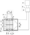
本実施形態の送風機20Aは、図7、図8に示すように、第1、第2ファン22A、23A、各ファン22A、23Aを収容する送風ケース21A、および電動機25を有して構成される。各ファン22A、23Aは、回転軸252を交差する方向に空気が流れるクロスフローファンで構成されている。
第1ファン22Aは、回転軸252の周りに配置された複数枚の羽根221A、および各羽根221Aにおける回転軸252の一端側を連結する第1エンドプレート261を有する。各羽根221Aは、各羽根221Aの間を空気が流通可能なように、電動機25における回転軸252の周りに間隔をあけて環状に配置されている。
第1エンドプレート261は、各羽根221Aの一端側に連結されると共に、電動機25の回転軸252に連結されている。第1エンドプレート261には、各羽根221Aが結合される部位の背面側に、第3誘導加熱コイル55を収容する第3溝部261aが形成されている。
また、第2ファン23Aは、回転軸252の周りに配置された複数枚の羽根231A、および各羽根231Aにおける回転軸252の他端側を連結する第2エンドプレート262を有する。各羽根231Aは、各羽根231Aの間を空気が流通可能なように、電動機25における回転軸252の周りに間隔をあけて環状に配置されている。
第2エンドプレート262は、各羽根231Aの他端側に連結されると共に、電動機25の回転軸252に連結されている。第2エンドプレート262には、各羽根231Aが結合される部位の背面側に、第4誘導加熱コイル56を収容する第4溝部262aが形成されている。
本実施形態の各エンドプレート261、262は、各羽根221A、231Aを連結すると共に、電動機25からの回転駆動力を各羽根221A、231Aへ伝達する連結部26を構成する。
各ファン22A、23Aは、回転軸252の方向に並ぶように中間プレート27により連結されており、1つの筒状体として構成されている。中間プレート27は、円環状に形成されており、各羽根221A、231Aを連結している。なお、中間プレート27は、電動機25の回転軸252には連結されていない。
続いて、送風ケース21Aには、図7に示すように、吸込口211Aと吐出口213Aとの間に、ファン22の回転により発生した気流の逆流を防止するスタビライザ215が形成されている。スタビライザ215は、ファン22側に向かって突出する突出形状を有する。
送風ケース21Aの内部では、ファン22の回転に伴いスタビライザ215付近を中心とする渦流(すなわち、循環流)が誘起される。これにより、送風ケース21Aの吸込口211Aから吸い込まれた空気が回転軸252を交差する方向に沿って流れ、吐出口213Aから吹き出される。
本実施形態では、各羽根221A、231Aを各エンドプレート261、262よりも熱伝導率λの高い材料で構成し、各エンドプレート261、262を各羽根221A、231Aよりも電気抵抗率ρと透磁率μとの積算値の高い材料で構成している。
具体的には、本実施形態では、各羽根221A、231Aをアルミニウムで構成し、各エンドプレート261、262を鉄で構成している。
各羽根221A、231Aは、各エンドプレート261、262よりも熱伝導率λの高い材料であればよく、例えば、熱伝導率λが高いアルミニウムを主成分とする材料(例えば、アルミニウム合金)や、銅を主成分とする材料で構成してもよい。
また、各エンドプレート261、262は、各羽根221A、231Aよりも電気抵抗率ρと透磁率μとの積算値が高い材料であればよく、例えば、電気抵抗率ρと透磁率μとの積算値が高い鉄を主成分とする材料(例えば、ステンレス)で構成してもよい。
本実施形態の各ファン22A、23Aの中間プレート27は、比較的軽量となるアルミニウムで構成している。なお、中間プレート27は、軽量であることが望ましいことから、樹脂等の材料で構成してもよい。
続いて、本実施形態の送電回路50は、各ファン22A、23Aを誘導加熱する第3、第4誘導加熱コイル55、56、共振回路53、および電源回路54を有して構成される。
第3誘導加熱コイル55は、第1エンドプレート261と対向するように配置されている。本実施形態の第3誘導加熱コイル55は、第1エンドプレート261における各羽根221Aの反対側に配置されている。
また、第3誘導加熱コイル55は、第1エンドプレート261に形成された第3溝部261aの内部に対応する円環状の形状のコイルで構成され、第3溝部261aの内部に第3溝部261aと非接触に収容されている。
第4誘導加熱コイル56は、第2エンドプレート262と対向するように配置されている。本実施形態の第4誘導加熱コイル56は、第2エンドプレート262における各羽根231Aの反対側に配置されている。
また、第4誘導加熱コイル56は、第2エンドプレート262に形成された第4溝部262aの内部に対応する円環状の形状のコイルで構成され、第4溝部262aの内部に第4溝部262aと非接触に収容されている。
その他の構成は、第1実施形態と同様である。次に、上記構成に係る本実施形態の送風装置2の作動を説明する。
まず、駆動回路からモータ本体部251のコアに電力が供給されると、電動機25の回転軸252が回転する。そして、各ファン22A、23Aは、回転軸252の回転に連動して回転する。各ファン22A、23Aの回転により、図7に示すように、送風ケース21Aの吸込口211Aから吸い込まれた空気が、回転軸252と交差する方向に各ファン22A、23Aの内部を通過して吹き出される。そして、各ファン22A、23Aから吹き出された空気は、送風ケース21Aの吐出口213A、および空調用ダクトを介して車室内へ吹き出される。
この状態で、送電回路50の電源回路54から交流電流が各誘導加熱コイル55、56へ供給されると、各誘導加熱コイル55、56の周囲に磁界が発生する。この際、各ファン22A、23Aの各エンドプレート261、262には、各誘導加熱コイル55、56の周囲に発生した磁界を打ち消す方向に渦電流(すなわち、誘導電流)が流れて発熱する。そして、各エンドプレート261、262の熱は、各羽根221A、231Aを介して、送風ケース21に吸い込まれた空気に放熱される。これにより、ファン22に吸い込まれた空気が加熱され、ファン22で加熱された空気が空調用ダクトを介して車室内へ吹き出される。
本実施形態の送風装置2は、各羽根221A、231Aを各エンドプレート261、262よりも熱伝導率の高い材料で構成し、各エンドプレート261、262を各羽根221A、231Aよりも透磁率と電気抵抗率との積算値が高い材料で構成している。
これよれば、各エンドプレート261、262を誘導加熱により効率よく加熱すると共に、誘導加熱により加熱された各エンドプレート261、262の熱を、熱伝導率の高い各羽根221A、231Aを介して空気側へ効率よく放熱させることが可能となる。
従って、本実施形態の送風装置2によれば、誘導加熱によるファン22A、23Aの加熱の効率化、およびファン22A、23Aから空気への放熱の効率化を両立させることが可能となる。
(他の実施形態)
以上、本開示の実施形態について説明したが、本開示は上述の実施形態に限定されるものではなく、適宜変更が可能である。例えば、以下のように種々変形可能である。
以上、本開示の実施形態について説明したが、本開示は上述の実施形態に限定されるものではなく、適宜変更が可能である。例えば、以下のように種々変形可能である。
(1)上述の各実施形態では、本開示の送風装置2を車両用空調装置に適用する例について説明したが、これに限定されない。送風装置2は、車両等の移動体に限らず、家庭や工場等に利用される定置型の空調装置に適用してもよい。また、送風装置2は、空調装置に限らず、例えば、機器の温度を調整する装置に適用してもよい。なお、送風装置2を空調装置に適用する場合、送風機20の位置は、蒸発器13やヒータコア14といった温度調整機器の空気流れ下流側ではなく、当該温度調整機器の空気流れ上流側に配置してもよい。
(2)上述の各実施形態では、ファン22の各構成要素をろう付け接合により一体化する例について説明したが、これに限らず、各構成要素を溶接により一体に構成してもよい。また、ファン22の各構成要素に金属材料以外の材料(例えば、樹脂)で構成される要素がある場合には、当該要素については別工程で連結すればよい。
(3)上述の各実施形態では、各誘導加熱コイル51、52、55、56に対して単一の共振回路53を接続する例について説明したが、これに限定されない。すなわち、各誘導加熱コイル51、52、55、56に対応して共振回路53を複数設け、各誘導加熱コイル51、52、55、56に対して個別に共振回路53を接続してもよい。このような構成は、第2実施形態の如く、各誘導加熱コイル55、56との間にファン22A、23Aが介在して、距離が離れてしまう場合に好適である。
(4)上述の各実施形態の如く、各誘導加熱コイル51、52、55、56を各羽根221、221A、231Aよりも連結部に近接する位置に配置することが望ましいがこれに限定されない。例えば、各誘導加熱コイル51、52、55、56の一部が連結部よりも各羽根221、221A、231Aに近接する位置に配置されていてもよい。
(5)上述の各実施形態の如く、各誘導加熱コイル51、52、55、56を主板223等の連結部に形成した各溝部225、226、261a、262aに収容することが望ましいが、これに限定されない。各誘導加熱コイル51、52、55、56は、主板223等の連結部に近接する位置であれば他の位置に配置されていてもよい。
(6)上述の各実施形態の如く、各誘導加熱コイル51、52、55、56を主板223等の連結部における各羽根221、221A、231Aの反対側に配置することが望ましいが、これに限定されない。各誘導加熱コイル51、52、55、56は、主板223等の連結部に近接する位置であれば他の位置に配置されていてもよい。
(7)上述の各実施形態では、送風装置2自体が共振回路53、および電源回路54を備える例について説明したが、これに限定されず、他の装置の電源回路等から各誘導加熱コイル51、52、55、56に交流電流を供給する構成としてもよい。
(8)上述の第1実施形態では、第1、第2誘導加熱コイル51、52を主板223に近接する位置に配置する例について説明したが、これに限定されない。例えば、第1、第2誘導加熱コイル51、52のうち、一方を主板223に近接する位置に配置してもよい。勿論、第1、第2誘導加熱コイル51、52に加えて、第3の誘導加熱コイルを追加してもよい。
(9)上述の第2実施形態では、第3、第4誘導加熱コイル55、56を各エンドプレート261、262に近接する位置に配置する例について説明したが、これに限定されない。例えば、第3、第4誘導加熱コイル55、56に加えて、第3の誘導加熱コイルを追加してもよい。
(10)上述の各実施形態において、実施形態を構成する要素は、特に必須であると明示した場合および原理的に明らかに必須であると考えられる場合等を除き、必ずしも必須のものではないことは言うまでもない。また、上述の各実施形態は、可能な範囲で適宜組み合わせることができる。
(11)上述の各実施形態において、実施形態の構成要素の個数、数値、量、範囲等の数値が言及されている場合、特に必須であると明示した場合および原理的に明らかに特定の数に限定される場合等を除き、その特定の数に限定されない。
(12)上述の各実施形態において、構成要素等の形状、位置関係、材料等に言及するときは、特に明示した場合および原理的に特定の形状、位置関係、材料等に限定される場合等を除き、その形状、位置関係、材料等に限定されない。
Claims (6)
- 空気を送風する送風装置であって、
回転することにより空気を吸い込んで吹き出すファン(22、22A、23A)と、
前記ファンを回転駆動する電動機(25)と、
前記ファンを誘導加熱により加熱する誘導加熱コイル(51、52、55、56)と、を備え、
前記ファンは、空気が流通可能なように間隔をあけて配置された複数枚の羽根(221、221A、231A)、および前記複数枚の羽根を連結すると共に前記電動機からの回転駆動力を前記複数枚の羽根へ伝達する連結部(223、26)を有し、
前記複数枚の羽根は、前記連結部よりも熱伝導率の高い材料で構成され、
前記連結部は、前記複数枚の羽根よりも透磁率と電気抵抗率との積算値が高い材料で構成されている送風装置。 - 前記誘導加熱コイルは、誘導加熱によって渦電流が前記連結部に流れるように、前記複数枚の羽根、および前記連結部のうち前記連結部に近い位置に配置されている請求項1に記載の送風装置。
- 前記連結部には、前記誘導加熱コイルを収容する溝部(225、226、261a、262a)が形成されており、
前記誘導加熱コイルは、前記溝部の内部に前記溝部と非接触に収容されている請求項1または2に記載の送風装置。 - 前記ファン(22)は、軸方向の一端側から吸い込んだ空気を径方向に吹き出す遠心ファンで構成されており、
前記連結部(223)は、前記複数枚の羽根(22)における前記ファンの軸方向の他端側に連結されており、
前記誘導加熱コイル(51、52)は、前記ファンの軸方向の他端側であって前記連結部における前記複数枚の羽根と反対側に配置されている請求項1ないし3のいずれか1つに記載の送風装置。 - 前記誘導加熱コイルに交流電流を供給する交流供給部(53、54)を備え、
前記ファンは、前記交流供給部から前記誘導加熱コイルへ前記交流電流が供給された際に、誘導加熱により加熱される請求項1ないし4のいずれか1つに記載の送風装置。 - 前記連結部は、鉄を主成分とする材料で構成され、
前記複数枚の羽根は、アルミニウムを主成分とする材料で構成される請求項1ないし5のいずれか1つに記載の送風装置。
Priority Applications (1)
| Application Number | Priority Date | Filing Date | Title |
|---|---|---|---|
| JP2017514015A JP6330971B2 (ja) | 2015-04-20 | 2016-03-17 | 送風装置 |
Applications Claiming Priority (2)
| Application Number | Priority Date | Filing Date | Title |
|---|---|---|---|
| JP2015-086024 | 2015-04-20 | ||
| JP2015086024 | 2015-04-20 |
Publications (1)
| Publication Number | Publication Date |
|---|---|
| WO2016170880A1 true WO2016170880A1 (ja) | 2016-10-27 |
Family
ID=57143951
Family Applications (1)
| Application Number | Title | Priority Date | Filing Date |
|---|---|---|---|
| PCT/JP2016/058599 Ceased WO2016170880A1 (ja) | 2015-04-20 | 2016-03-17 | 送風装置 |
Country Status (2)
| Country | Link |
|---|---|
| JP (1) | JP6330971B2 (ja) |
| WO (1) | WO2016170880A1 (ja) |
Cited By (4)
| Publication number | Priority date | Publication date | Assignee | Title |
|---|---|---|---|---|
| DE102017210527A1 (de) * | 2017-06-22 | 2018-12-27 | E.G.O. Elektro-Gerätebau GmbH | Pumpe für ein Elektrogerät und Elektrogerät mit einer Fluidführung und einer solchen Pumpe |
| EP3608469A3 (de) * | 2018-08-06 | 2020-05-06 | E.G.O. Elektro-Gerätebau GmbH | Wäschetrockner und verfahren zum trocknen von wäsche mit einem wäschetrockner |
| JP2022030247A (ja) * | 2020-08-06 | 2022-02-18 | 株式会社久保田鉄工所 | 電動ポンプ |
| CN114060310A (zh) * | 2021-11-12 | 2022-02-18 | 珠海格力电器股份有限公司 | 一种离心风叶及包括其的一体式空调及控制方法 |
Families Citing this family (2)
| Publication number | Priority date | Publication date | Assignee | Title |
|---|---|---|---|---|
| CN109827330A (zh) * | 2019-01-25 | 2019-05-31 | 珠海格力电器股份有限公司 | 空气净化器的风机组件及空气净化器 |
| CN112443968A (zh) * | 2019-08-30 | 2021-03-05 | 广东美的环境电器制造有限公司 | 送风设备 |
Citations (3)
| Publication number | Priority date | Publication date | Assignee | Title |
|---|---|---|---|---|
| JPH04320759A (ja) * | 1991-04-19 | 1992-11-11 | Mitsubishi Electric Home Appliance Co Ltd | 温風暖房機 |
| JPH11262600A (ja) * | 1998-03-18 | 1999-09-28 | Matsushita Seiko Co Ltd | 換気乾燥機 |
| JP2015033970A (ja) * | 2013-08-09 | 2015-02-19 | 株式会社日本自動車部品総合研究所 | 空調装置用送風ユニット |
-
2016
- 2016-03-17 WO PCT/JP2016/058599 patent/WO2016170880A1/ja not_active Ceased
- 2016-03-17 JP JP2017514015A patent/JP6330971B2/ja not_active Expired - Fee Related
Patent Citations (3)
| Publication number | Priority date | Publication date | Assignee | Title |
|---|---|---|---|---|
| JPH04320759A (ja) * | 1991-04-19 | 1992-11-11 | Mitsubishi Electric Home Appliance Co Ltd | 温風暖房機 |
| JPH11262600A (ja) * | 1998-03-18 | 1999-09-28 | Matsushita Seiko Co Ltd | 換気乾燥機 |
| JP2015033970A (ja) * | 2013-08-09 | 2015-02-19 | 株式会社日本自動車部品総合研究所 | 空調装置用送風ユニット |
Cited By (6)
| Publication number | Priority date | Publication date | Assignee | Title |
|---|---|---|---|---|
| DE102017210527A1 (de) * | 2017-06-22 | 2018-12-27 | E.G.O. Elektro-Gerätebau GmbH | Pumpe für ein Elektrogerät und Elektrogerät mit einer Fluidführung und einer solchen Pumpe |
| DE102017210527B4 (de) * | 2017-06-22 | 2021-01-14 | E.G.O. Elektro-Gerätebau GmbH | Pumpe für ein Elektrogerät und Elektrogerät mit einer Fluidführung und einer solchen Pumpe |
| EP3608469A3 (de) * | 2018-08-06 | 2020-05-06 | E.G.O. Elektro-Gerätebau GmbH | Wäschetrockner und verfahren zum trocknen von wäsche mit einem wäschetrockner |
| US11021837B2 (en) | 2018-08-06 | 2021-06-01 | E.G.O. Elektro-Geraetebau Gmbh | Tumble dryer and method for drying laundry using a tumble dryer |
| JP2022030247A (ja) * | 2020-08-06 | 2022-02-18 | 株式会社久保田鉄工所 | 電動ポンプ |
| CN114060310A (zh) * | 2021-11-12 | 2022-02-18 | 珠海格力电器股份有限公司 | 一种离心风叶及包括其的一体式空调及控制方法 |
Also Published As
| Publication number | Publication date |
|---|---|
| JPWO2016170880A1 (ja) | 2017-09-28 |
| JP6330971B2 (ja) | 2018-05-30 |
Similar Documents
| Publication | Publication Date | Title |
|---|---|---|
| JP6330971B2 (ja) | 送風装置 | |
| US10549598B2 (en) | Vehicle air-conditioning apparatus | |
| CN106415999B (zh) | 用于鼓风装置和空调和/或加热通风系统的电动马达 | |
| JP5895753B2 (ja) | 空調装置用送風ユニット | |
| WO2017073154A1 (ja) | 車両用空調装置 | |
| US20210108828A1 (en) | Magnetic induction furnace, cooler or magnetocaloric fluid heat pump with varied conductive plate configurations | |
| CN113711473A (zh) | 具有冷却单元的驱动单元 | |
| JP2017089479A (ja) | 送風装置 | |
| JP6319513B2 (ja) | 送風装置 | |
| JP2897083B2 (ja) | 温風暖房機 | |
| CN217520058U (zh) | 热风导出装置 | |
| RU2463697C2 (ru) | Вентилятор | |
| KR20230045877A (ko) | 외전형 모터 | |
| JP6349102B2 (ja) | 空調装置用送風ユニット | |
| JP2000105516A (ja) | 誘導加熱定着装置 | |
| CN224162740U (zh) | 电磁加热风扇 | |
| JP2016196209A (ja) | 車両用空調ユニット | |
| CN114234444B (zh) | 热风导出装置 | |
| JP6962735B2 (ja) | 熱移動装置 | |
| JP2023122602A (ja) | 加温装置 | |
| CN113007791A (zh) | 一种空调 | |
| WO2010058666A1 (ja) | 空気調和機 | |
| JP2010275907A (ja) | 冷却装置 | |
| JP7732380B2 (ja) | 空調装置 | |
| TW201429315A (zh) | 利用風扇同時產生氣流及交變磁場之發熱裝置 |
Legal Events
| Date | Code | Title | Description |
|---|---|---|---|
| 121 | Ep: the epo has been informed by wipo that ep was designated in this application |
Ref document number: 16782902 Country of ref document: EP Kind code of ref document: A1 |
|
| ENP | Entry into the national phase |
Ref document number: 2017514015 Country of ref document: JP Kind code of ref document: A |
|
| NENP | Non-entry into the national phase |
Ref country code: DE |
|
| 122 | Ep: pct application non-entry in european phase |
Ref document number: 16782902 Country of ref document: EP Kind code of ref document: A1 |