WO2016167139A1 - 受信装置、受信方法、およびプログラム - Google Patents
受信装置、受信方法、およびプログラム Download PDFInfo
- Publication number
- WO2016167139A1 WO2016167139A1 PCT/JP2016/060896 JP2016060896W WO2016167139A1 WO 2016167139 A1 WO2016167139 A1 WO 2016167139A1 JP 2016060896 W JP2016060896 W JP 2016060896W WO 2016167139 A1 WO2016167139 A1 WO 2016167139A1
- Authority
- WO
- WIPO (PCT)
- Prior art keywords
- time stamp
- unit
- data stream
- receiving
- increment value
- Prior art date
- Legal status (The legal status is an assumption and is not a legal conclusion. Google has not performed a legal analysis and makes no representation as to the accuracy of the status listed.)
- Ceased
Links
Images







Classifications
-
- H—ELECTRICITY
- H04—ELECTRIC COMMUNICATION TECHNIQUE
- H04N—PICTORIAL COMMUNICATION, e.g. TELEVISION
- H04N21/00—Selective content distribution, e.g. interactive television or video on demand [VOD]
- H04N21/40—Client devices specifically adapted for the reception of or interaction with content, e.g. set-top-box [STB]; Operations thereof
- H04N21/43—Processing of content or additional data, e.g. demultiplexing additional data from a digital video stream; Elementary client operations, e.g. monitoring of home network or synchronising decoder's clock; Client middleware
- H04N21/434—Disassembling of a multiplex stream, e.g. demultiplexing audio and video streams, extraction of additional data from a video stream; Remultiplexing of multiplex streams; Extraction or processing of SI; Disassembling of packetised elementary stream
- H04N21/4344—Remultiplexing of multiplex streams, e.g. by modifying time stamps or remapping the packet identifiers
-
- H—ELECTRICITY
- H04—ELECTRIC COMMUNICATION TECHNIQUE
- H04N—PICTORIAL COMMUNICATION, e.g. TELEVISION
- H04N21/00—Selective content distribution, e.g. interactive television or video on demand [VOD]
- H04N21/20—Servers specifically adapted for the distribution of content, e.g. VOD servers; Operations thereof
- H04N21/23—Processing of content or additional data; Elementary server operations; Server middleware
- H04N21/242—Synchronisation processes, e.g. processing of PCR [Programme Clock References]
-
- H—ELECTRICITY
- H04—ELECTRIC COMMUNICATION TECHNIQUE
- H04N—PICTORIAL COMMUNICATION, e.g. TELEVISION
- H04N21/00—Selective content distribution, e.g. interactive television or video on demand [VOD]
- H04N21/40—Client devices specifically adapted for the reception of or interaction with content, e.g. set-top-box [STB]; Operations thereof
- H04N21/43—Processing of content or additional data, e.g. demultiplexing additional data from a digital video stream; Elementary client operations, e.g. monitoring of home network or synchronising decoder's clock; Client middleware
- H04N21/4302—Content synchronisation processes, e.g. decoder synchronisation
- H04N21/4305—Synchronising client clock from received content stream, e.g. locking decoder clock with encoder clock, extraction of the PCR packets
-
- H—ELECTRICITY
- H04—ELECTRIC COMMUNICATION TECHNIQUE
- H04N—PICTORIAL COMMUNICATION, e.g. TELEVISION
- H04N21/00—Selective content distribution, e.g. interactive television or video on demand [VOD]
- H04N21/40—Client devices specifically adapted for the reception of or interaction with content, e.g. set-top-box [STB]; Operations thereof
- H04N21/43—Processing of content or additional data, e.g. demultiplexing additional data from a digital video stream; Elementary client operations, e.g. monitoring of home network or synchronising decoder's clock; Client middleware
- H04N21/434—Disassembling of a multiplex stream, e.g. demultiplexing audio and video streams, extraction of additional data from a video stream; Remultiplexing of multiplex streams; Extraction or processing of SI; Disassembling of packetised elementary stream
-
- H—ELECTRICITY
- H04—ELECTRIC COMMUNICATION TECHNIQUE
- H04N—PICTORIAL COMMUNICATION, e.g. TELEVISION
- H04N21/00—Selective content distribution, e.g. interactive television or video on demand [VOD]
- H04N21/40—Client devices specifically adapted for the reception of or interaction with content, e.g. set-top-box [STB]; Operations thereof
- H04N21/43—Processing of content or additional data, e.g. demultiplexing additional data from a digital video stream; Elementary client operations, e.g. monitoring of home network or synchronising decoder's clock; Client middleware
- H04N21/435—Processing of additional data, e.g. decrypting of additional data, reconstructing software from modules extracted from the transport stream
-
- H—ELECTRICITY
- H04—ELECTRIC COMMUNICATION TECHNIQUE
- H04N—PICTORIAL COMMUNICATION, e.g. TELEVISION
- H04N21/00—Selective content distribution, e.g. interactive television or video on demand [VOD]
- H04N21/40—Client devices specifically adapted for the reception of or interaction with content, e.g. set-top-box [STB]; Operations thereof
- H04N21/43—Processing of content or additional data, e.g. demultiplexing additional data from a digital video stream; Elementary client operations, e.g. monitoring of home network or synchronising decoder's clock; Client middleware
- H04N21/44—Processing of video elementary streams, e.g. splicing a video clip retrieved from local storage with an incoming video stream or rendering scenes according to encoded video stream scene graphs
-
- H—ELECTRICITY
- H04—ELECTRIC COMMUNICATION TECHNIQUE
- H04N—PICTORIAL COMMUNICATION, e.g. TELEVISION
- H04N21/00—Selective content distribution, e.g. interactive television or video on demand [VOD]
- H04N21/80—Generation or processing of content or additional data by content creator independently of the distribution process; Content per se
- H04N21/85—Assembly of content; Generation of multimedia applications
- H04N21/854—Content authoring
- H04N21/8547—Content authoring involving timestamps for synchronizing content
Definitions
- the present disclosure relates to a reception device, a reception method, and a program, and particularly, for example, a reception device, a reception method, and a method suitable for recording or redistributing a broadcast TS (transport stream). Regarding the program.
- data such as video and audio are packetized and multiplexed in a format that can be synchronized and reproduced.
- TS MPEG-2 Transport Stream
- a TS is composed of a plurality of TS packets (fixed length of 188 bytes, hereinafter simply referred to as a packet).
- recording is performed after adding a time stamp to each packet on the receiving side.
- This time stamp represents the time at which each packet arrived at the receiving side (value of 27 MHz accuracy), and is used for controlling reproduction timing at the time of reproduction after recording.
- the clock recovery circuit is a bitstream parser that extracts PCR (Program Clock Reference) from the TS, a PLL (Phase Lock Loop) circuit that locks the system clock signal to the PCR, and a clock counter for the system clock signal
- PCR Program Clock Reference
- PLL Phase Lock Loop
- a time stamp generating circuit that generates a time stamp based on the value (see, for example, Patent Document 1).
- a receiving apparatus that records a received TS requires a clock recovery circuit for generating a time stamp, but the clock recovery circuit has a complicated circuit configuration and is expensive. Therefore, a proposal of a mechanism capable of generating a highly accurate time stamp with a simple and low-cost circuit configuration is expected.
- the present disclosure has been made in view of such a situation, and is capable of generating a time stamp with a simple and low-cost circuit configuration.
- a receiving apparatus includes a receiving unit that receives a data stream configured by a series of packets, an acquiring unit that acquires a transmission parameter from the received data stream, and the acquired transmission parameter.
- a time stamp increment specifying unit for identifying a corresponding time stamp increment, a time stamp calculating unit for updating the time stamp by adding the identified time stamp increment to a previous time stamp, and an updated A time stamp adding unit for adding the time stamp to the packets constituting the data stream.
- the time stamp increment specifying unit is configured to calculate the transmission rate based on the acquired transmission parameter, and to calculate the time stamp increment based on the calculated transmission rate.
- a value calculator configured to calculate the transmission rate based on the acquired transmission parameter, and to calculate the time stamp increment based on the calculated transmission rate.
- the time stamp increment value specifying unit may include a conversion table in which the time stamp increment value is associated with the acquired transmission parameter.
- the time stamp increment value specifying unit can specify the time stamp increment value corresponding to the changed transmission parameter when the acquired transmission parameter is changed.
- the time stamp calculation unit can initialize the time stamp when the channel selection for receiving the data stream is switched.
- the transmission rate, the time stamp increment value, and the time stamp can be treated as rational numbers.
- the receiving apparatus may further include a packet selection unit that selectively outputs the packet with the time stamp added thereto.
- a reception method is a reception method of a reception device, wherein the reception device receives a data stream composed of a series of packets, and obtains transmission parameters from the received data stream.
- An obtaining step for identifying the time stamp increment value corresponding to the obtained transmission parameter, and adding the identified time stamp increment value to the previous time stamp And a time stamp adding step of adding the updated time stamp to the packet constituting the data stream.
- a program includes a reception unit that receives a data stream including a series of packets, an acquisition unit that acquires transmission parameters from the received data stream, and the acquired transmission
- a time stamp increment value identifying unit that identifies a time stamp increment value corresponding to the parameter
- a time stamp calculating unit that updates the time stamp by adding the identified time stamp increment value to a previous time stamp, and an update
- the time stamp added is made to function as a time stamp adding unit for adding the time stamp to the packet constituting the data stream.
- a transmission parameter is obtained from a received data stream, a time stamp increment value corresponding to the obtained transmission parameter is identified, and the identified time stamp increment value is a previous time stamp. Is added to the packet, and the updated time stamp is added to the packet constituting the data stream.
- FIG. 11 is a block diagram illustrating a configuration example when a receiving device is applied to a recording system. It is a block diagram which shows the structural example at the time of applying a receiver to a delivery system. And FIG. 11 is a block diagram illustrating a configuration example of a general-purpose computer.
- a receiving apparatus to which the present disclosure is applied calculates a transmission rate from an encoding parameter corresponding to transmission path encoding information, and generates a time stamp using the calculated transmission rate.
- the transmission parameter is obtained from the demodulation result of the received signal, and the time stamp increment value is calculated based on the transmission parameter. Then, an updated time stamp value is added to each packet by incrementing the time stamp increment value.
- the time stamp value calculation process it is expressed in the form of a rational number (a set of numerator and denominator) in order to avoid error accumulation. Note that the time stamp value can be initialized to a desired value when the received TS becomes discontinuous, such as at the time of channel selection switching.
- packets corresponding to a plurality of services are multiplexed in the TS, but only the packets of services (programs) selected by the user are output to the subsequent stage. Thereby, the bit rate of TS can be reduced.
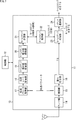
- FIG. 2 illustrates a first configuration example of a receiving device to which the present disclosure is applied.
- the receiving device 11 includes a control unit 12 and a reception processing unit 13.
- the control unit 12 controls the reception processing unit 13.
- the reception processing unit 13 acquires a TS from a broadcast wave input from an antenna or the like according to control from the control unit 12, adds a time stamp to each packet constituting the TS, and outputs it to the subsequent stage.
- the reception processing unit 13 includes a tuner unit 14, a demodulation unit 15, an error correction unit 16, a transmission parameter acquisition unit 17, a transmission rate calculation unit 18, a time stamp increment value calculation unit 19, a time stamp increment value holding unit 20, and a time stamp calculation.
- the unit 21 includes a time stamp holding unit 22, a time stamp adding unit 23, and a packet selecting unit 24.
- the tuner unit 14 acquires a channel signal (transmission path encoded signal) from a broadcast wave input from an antenna, a CATV cable, or the like, and outputs it to the demodulation unit 15.
- the demodulation unit 15 performs demodulation processing such as synchronization processing and equivalent processing on the transmission path encoded signal from the tuner unit 14 and outputs the demodulated signal to the error correction unit 16.
- the demodulation unit 15 acquires a transmission parameter from the transmission path encoded signal from the tuner unit 14 and supplies the transmission parameter to the transmission parameter acquisition unit 17.
- the error correction unit 16 performs error correction processing on the demodulated signal and outputs the signal (TS) after error correction processing to the time stamp adding unit 23.
- the transmission parameter acquisition unit 17 requests the transmission parameter from the demodulation unit 15 and outputs the obtained transmission parameter to the transmission rate calculation unit 18.
- the transmission rate calculation unit 18 calculates a transmission rate based on the transmission parameters (details will be described later) and notifies the time stamp increment value calculation unit 19 of the transmission rate.
- the transmission rate notified to the time stamp increment calculation unit 19 is transmitted in the form of a rational number.
- values exchanged between subsequent components are also handled in the form of rational numbers in order to avoid error accumulation.
- the time stamp increment value calculation unit 19 calculates a time stamp increment value based on the transmission rate notified from the transmission rate calculation unit 18 (details will be described later), and calculates the time stamp increment value as a time stamp increment value holding unit 20. To supply.
- the time stamp increment value holding unit 20 temporarily holds the time stamp increment value supplied from the time stamp increment value calculation unit 19.
- the time stamp calculation unit 21 Based on the time stamp value added to the previous packet held in the time stamp holding unit 22 and the time stamp increment value held in the time stamp increment value holding unit 20, the time stamp calculation unit 21 The time stamp value added to the packet is calculated (details will be described later), and the calculated time stamp value is notified to the time stamp holding unit 22.
- the time stamp holding unit 22 supplies the held time stamp value to the time stamp calculating unit 21 and updates the held time stamp value with the time stamp value notified from the time stamp calculating unit 21. Further, the time stamp holding unit 22 initializes the value of the time stamp to be held to an initial value (for example, 0) according to the control from the control unit 12.
- the time stamp adding unit 23 adds a time stamp held in the time stamp holding unit 22 to each packet of the error-corrected signal (TS) input from the error correction unit 16 and outputs the packet to the packet selection unit 24. To do.
- the time stamp adding unit 23 adds time stamps to all packets, but time stamps may be added only to packets that are spaced apart from each other by a predetermined interval.
- the packet selection unit 24 selects a designated packet (such as one corresponding to the program selected by the user) from among the packets to which time stamps are added, and outputs the selected packet to the subsequent stage. .
- Fig. 3 shows a process for dealing with channel selection switching. This process is repeatedly executed while the receiving apparatus 11 outputs a TS with a time stamp.
- step S11 the control unit 12 confirms whether or not channel selection has been switched, and waits until channel selection switching occurs. If channel selection switching has occurred, the process proceeds to step S12, and the time stamp holding unit 22 initializes the value of the held time stamp in accordance with control from the control unit 12. Thereafter, the process is started again from step S11.
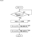
- FIG. 4 shows processing for dealing with switching of transmission parameters. This process is repeatedly executed while the receiving apparatus 11 outputs a TS with a time stamp.
- step S21 the control unit 12 confirms whether or not the transmission parameter acquisition unit 17 has changed the transmission parameter acquired from the demodulation unit 15, and waits until the transmission parameter is changed. If a change in transmission parameter occurs, the process proceeds to step S22.
- step S ⁇ b> 22 the transmission rate calculation unit 18 recalculates the transmission rate based on the changed transmission parameter in accordance with the control from the control unit 12, and notifies the time stamp increment value calculation unit 19.
- step S 23 the time stamp increment value calculation unit 19 recalculates the time stamp increment value based on the recalculated transmission rate, and supplies the time stamp increment value as a result of the calculation to the time stamp increment value holding unit 20. To do.
- step S ⁇ b> 24 the time stamp increment value holding unit 20 stores the newly supplied time stamp increment value. Thereafter, the process is started again from step S21.
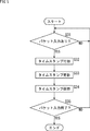
- FIG. 5 shows a process for adding a time stamp to each packet constituting the error-corrected TS.
- step S31 the time stamp adding unit 23 confirms whether there is an error-corrected TS packet input from the error correction unit 16, and waits until there is a packet input. If there is a packet input, the process proceeds to step S32. In step S ⁇ b> 32, the time stamp adding unit 23 adds the time stamp held in the time stamp holding unit 22 to the packet input from the error correction unit 16.
- step S33 the time stamp calculation unit 21 calculates a new time stamp value and notifies the time stamp holding unit 22 of the new time stamp value.
- step S34 the time stamp holding unit 22 updates the currently held time stamp value to a new time stamp value.
- step S35 the control unit 12 determines whether or not the packet input to the time stamp adding unit 23 is completed, and returns the process to step S31 until it is determined that the packet input is completed, and repeats the subsequent steps. If it is determined in step S35 that the packet input to the time stamp adding unit 23 has been completed, the process ends.
- a highly accurate time stamp can be generated and added to a TS packet with a simple and low-cost circuit configuration.
- the calculation method of the transmission rate depends on the digital broadcasting standard.
- the transmission rate R can be calculated by the following equation (1).
- R (2/3) * 3 * S * (204/208) * (188/204) * (N / 48) ...
- the unit of the transmission rate R is Mbps (bit per second).
- S in the equation (1) is a symbol rate (28.860 Mbaud).
- N is the number of assigned slots (an integer from 0 to 48).
- the number N of assigned slots as a transmission parameter is transmitted as part of TMCC (Transmission Multiplexing Configuration Control) information.
- TMCC information is a control signal transmitted separately from TS.
- demodulation processing and error correction processing are performed based on this TMCC information.
- F in the formula (2) indicates a reference clock frequency (27 MHz).
- T (i) T (i-1) + ⁇ T ... (3)
- the calculation method corresponding to the satellite digital broadcasting standard (BS digital broadcasting) in Japan has been described.
- the present disclosure is not limited to this and can be applied to all kinds of digital broadcasting standards. Is possible.
- the transmission rate R can be expressed as a rational number based on the equation (1) as follows.
- time stamp increment value ⁇ T can be expressed by a rational number as follows based on the equation (2).
- the time stamp T (i) can be expressed by a rational number as follows when i is 1 to 8, for example.
- the integer part of the numerical values described above is a value that is actually added as a time stamp to the TS packet. For example, 1698 is added as the time stamp T (1). 3396 is added as the time stamp T (2). 5094 is added as the time stamp T (3). 6793 is added as the time stamp T (4). 8491 is added as the time stamp T (5). 10189 is added as the time stamp T (6). 11887 is added as the time stamp T (7). 13586 is added as the time stamp T (8).
- FIG. 6 illustrates a second configuration example of the receiving device to which the present disclosure is applied.
- the receiving device 31 uses a LUT instead of executing the calculation of the transmission rate R and the time stamp increment value ⁇ T.
- the reception device 31 is obtained by replacing the transmission rate calculation unit 18 and the time stamp increment value calculation unit 19 of the reception device 11 shown in FIG. 2 with an address generation unit 32 and an LUT unit 33. Constituent elements common to the apparatus 11 are given the same reference numerals, and the description thereof will be omitted as appropriate.
- the address generation unit 32 generates an address value to be notified to the LUT unit 33 based on the transmission parameter supplied from the transmission parameter acquisition unit 17.
- the LUT unit 33 holds the LUT in which the time stamp increment value ⁇ T is associated with the transmission parameter, and the time stamp stored in the address value corresponding to the transmission parameter notified from the address generation unit 32
- the increment value ⁇ T is read and supplied to the time stamp increment value holding unit 20. Note that the time stamp increment value ⁇ T stored in the LUT unit 33 is also expressed in the form of a rational number (a combination of a numerator and a denominator).
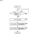
- FIG. 7 shows processing for dealing with switching of transmission parameters by the receiving device 31. This process is repeatedly executed while the receiving apparatus 31 outputs a TS with a time stamp.
- step S41 the control unit 12 checks whether the transmission parameter acquisition unit 17 has changed the transmission parameter acquired from the demodulation unit 15, and waits until the transmission parameter is changed. If a change in transmission parameter occurs, the process proceeds to step S42.
- step S ⁇ b> 42 the address generation unit 32 generates an address value corresponding to the changed transmission parameter and notifies the LUT unit 33 according to the control from the control unit 12.
- step S43 the LUT unit 33 supplies the time stamp increment value holding unit 20 with the time stamp increment value stored in the notified address value.
- step S44 the time stamp increment holding unit 20 stores the newly supplied time stamp increment. Thereafter, the process is started again from step S41.
- a highly accurate time stamp can be generated and added to a TS packet with a simple and low-cost circuit configuration.
- FIG. 8 shows an example of a LUT in which the number N of assigned slots as an encoding parameter is used as an address as it is when the satellite digital broadcasting standard (BS digital broadcasting) modulation scheme in Japan is TC8PSK.
- BS digital broadcasting satellite digital broadcasting standard
- the address generation unit 32 when the number N of assigned slots as an encoding parameter is 1, the address generation unit 32 generates 1 as an address value and notifies the LUT unit 33 of it.
- the time stamp increment value ⁇ T 37362 + 6/37 stored in the address value 1 is read and supplied to the time stamp increment value holding unit 20.
- FIG. 9 shows an output example of the receiving apparatuses 11 and 31 when the transmission rate of the received TS is constant.
- FIG. 3A shows the arrangement of packets output from the error correction unit 16.
- FIG. 7B shows the arrangement of packets with time stamps output from the time stamp adding unit 23.
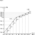
- FIG. 10 is a plot of time stamp values added to the time stamped packet shown in FIG. 9C.
- the horizontal axis indicates the packet number i
- the vertical axis indicates the time stamp value T (i) corresponding to i. Note that the time stamp value of the first packet TP (0) is T (0).
- T (i) Since the time stamp value T (i) is incremented by the time stamp increment value ( ⁇ T), T (i) increases monotonously. However, in the example of FIG. 9C, since TP (4) is discarded, the time stamp value is discontinuous only at that point, and the difference between T (3) and T (5) is twice ⁇ T. Yes.
- FIG. 11 is a plot of time stamp values added to packets output from the receiving apparatuses 11 and 31 when the transmission rate is changed during reception.
- the horizontal axis indicates the packet number i
- the vertical axis indicates the time stamp value T (i) corresponding to i.
- FIG. 12 is a plot of time stamp values added to packets output from the receiving apparatuses 11 and 31 when channel selection is switched.
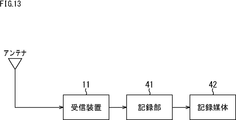
- FIG. 13 shows a configuration example when the receiving device 11 (or the receiving device 31) is applied to a recording system for recording a broadcasted TS on a recording medium.
- the TS with a time stamp output from the receiving device 11 is supplied to the recording unit 41 and recorded on the recording medium 42.
- the recording medium 42 includes, for example, a DVD, a Blu-ray (registered trademark) Disc, a hard disk drive, a flash memory, or the like.
- FIG. 14 shows a configuration example when the receiving device 11 (or the receiving device 31) is applied to a distribution system that distributes a broadcasted TS to a network.
- the time-stamped TS output from the receiving device 11 is converted into a format suitable for network distribution (such as RTP (Real-time Transport Protocol)) by the format conversion unit 51, and is transmitted to the network distribution unit 52. Supplied. Then, the time-stamped TS with the format converted is distributed to the network 53 by the network distribution unit 52.
- RTP Real-time Transport Protocol
- the series of processes described above can be executed by hardware or can be executed by software.
- a program constituting the software is installed in the computer.
- the computer includes, for example, a general-purpose personal computer capable of executing various functions by installing a computer incorporated in dedicated hardware and various programs.
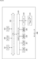
- FIG. 15 is a block diagram illustrating a configuration example of hardware of a computer that executes the above-described series of processes by a program.
- a CPU Central Processing Unit
- ROM Read Only Memory
- RAM Random Access Memory
- An input / output interface 205 is further connected to the bus 204.
- An input unit 206, an output unit 207, a storage unit 208, a communication unit 209, and a drive 210 are connected to the input / output interface 205.
- the input unit 206 includes a keyboard, a mouse, a microphone, and the like.
- the output unit 207 includes a display, a speaker, and the like.
- the storage unit 208 includes a hard disk, a nonvolatile memory, and the like.
- the communication unit 209 includes a network interface and the like.
- the drive 210 drives a removable medium 211 such as a magnetic disk, an optical disk, a magneto-optical disk, or a semiconductor memory.
- the CPU 201 loads the program stored in the storage unit 208 to the RAM 203 via the input / output interface 205 and the bus 204 and executes the program. A series of processing is performed.
- a receiver for receiving a data stream composed of a series of packets; An acquisition unit for acquiring transmission parameters from the received data stream; A time stamp increment specifying unit for specifying a time stamp increment corresponding to the acquired transmission parameter; A time stamp calculator for updating the time stamp by adding the identified time stamp increment to the previous time stamp; A receiving apparatus comprising: a time stamp adding unit that adds the updated time stamp to the packet constituting the data stream.
- the time stamp increment value specifying unit includes: A transmission rate calculator that calculates the transmission rate based on the acquired transmission parameter; The receiving apparatus according to (1), further comprising: a time stamp increment value calculation unit that calculates the time stamp increment value based on the calculated transmission rate.
- time stamp increment value specifying unit includes a conversion table in which the time stamp increment value is associated with the acquired transmission parameter.
- the time stamp increment value specifying unit specifies the time stamp increment value corresponding to the transmission parameter after the change when the acquired transmission parameter is changed. Any one of (1) to (3) Receiver.
- the receiving device further including a packet selection unit that selectively outputs the packet to which the time stamp is added.
- a packet selection unit that selectively outputs the packet to which the time stamp is added.
- Computer A receiver for receiving a data stream composed of a series of packets; An acquisition unit for acquiring transmission parameters from the received data stream; A time stamp increment specifying unit for specifying a time stamp increment corresponding to the acquired transmission parameter; A time stamp calculator for updating the time stamp by adding the identified time stamp increment to the previous time stamp; A program that causes the updated time stamp to function as a time stamp adding unit that adds the time stamp to the packet that constitutes the data stream.
Landscapes
- Engineering & Computer Science (AREA)
- Multimedia (AREA)
- Signal Processing (AREA)
- Computer Security & Cryptography (AREA)
- Two-Way Televisions, Distribution Of Moving Picture Or The Like (AREA)
- Synchronisation In Digital Transmission Systems (AREA)
Abstract
Description
仮にTSの伝送レートが一定であれば、パケット(固定長)単位の伝送時間が一定となるので、TSを構成する連続した2つのパケットのタイムスタンプの差分も一定になる。したがって、TSが放送されたときの伝送レートがわかり、且つ、タイムスタンプの初期値が決定できれば、クロックリカバリ回路を用いることなく、TSの各パケットに付加するタイムスタンプを計算できることになる。
図2は、本開示を適用した受信装置の第1の構成例を示している。この受信装置11は、制御部12、および受信処理部13から構成される。制御部12は、受信処理部13を制御する。受信処理部13は、制御部12からの制御に従い、アンテナなどから入力される放送波からTSを取得し、TSを構成する各パケットにタイムスタンプを付加して後段に出力する。
次に、受信装置11の動作について、図3乃至図5を参照して説明する。
次に、タイムスタンプなどの計算方法について具体的に説明する。
R=(2/3)*3*S*(204/208)*(188/204)*(N/48)
・・・(1)
ΔT=188*8*F/R
・・・(2)
T(i)=T(i-1)+ΔT
・・・(3)
タイムスタンプ計算部21における計算過程において、各段階の計算結果を有限桁数の実数値で表現した場合、丸め誤差が蓄積されてしまう。そこで、受信処理部13においては、構成要素間での数値のやり取りに有理数(分子と分母の組)を用いることで誤差蓄積を回避するようになされている。
R=(2/3)*3*(28860/1000)*(204/208)
*(188/204)*(22/48)
=19129/800
ΔT=188*8*27*800/19129
=1698+114/407
T(1)=T(0)+ΔT=1698+114/407
T(2)=T(1)+ΔT=3396+228/407
T(3)=T(2)+ΔT=5094+342/407
T(4)=T(3)+ΔT=6792+456/407=6793+49/407
T(5)=T(4)+ΔT=8491+163/407
T(6)=T(5)+ΔT=10189+277/407
T(7)=T(6)+ΔT=11887+391/407
T(8)=T(7)+ΔT=13585+505/407=13586+98/407
上述したように、伝送レートR、タイムスタンプ増分値ΔT、およびタイムスタンプT(i)の計算は、乗除算を含むために処理コストが高い。そこで、伝送レートRおよびタイムスタンプ増分値ΔTを計算する代わりに、伝送パラメータに対してタイムスタンプ増分値ΔTが対応付けられているLUT(Look Up Table)を用いて演算の処理コストを削減するようにしてもよい。
次に、受信装置31の動作について説明する。ただし、選局切り替えに対処するための処理、および、誤り訂正済のTSを構成する各パケットに対してタイムスタンプを付加するための処理については、上述した受信装置11の動作と同様なので、その説明は省略する。
ここで、LUT部33に保持されているLUTの一例を示す。図8は、日本国内における衛星デジタル放送規格(BSデジタル放送)の変調方式がTC8PSKである場合の符号化パラメータとしての割り当てスロット数Nをそのままアドレスとして用いたLUTの一例である。
図9は、受信したTSの伝送レートが一定である場合における受信装置11および31の出力例を示している。
図11は、伝送レートが受信途中で変更された場合における受信装置11および31から出力されるパケットに付加されているタイムスタンプの値をプロットしたものである。同図の横軸はパケット番号i、縦軸はiに対応するタイムスタンプ値T(i)を示している。
図12は、選局切り替えを行った場合における受信装置11および31から出力されるパケットに付加されているタイムスタンプの値をプロットしたものである。
図13は、受信装置11(または受信装置31)を、放送されたTSを記録媒体に記録する記録システムに応用した場合の構成例を示している。該記録システムでは、受信装置11から出力されるタイムスタンプ付きTSが記録部41に供給されて記録媒体42に記録される。この記録媒体42は、例えば、DVD,Blu-ray(登録商標) Disc、ハードディスクドライブ、フラッシュメモリなどからなる。
(1)
パケットが連なって構成されるデータストリームを受信する受信部と、
受信された前記データストリームから伝送パラメータを取得する取得部と、
取得された前記伝送パラメータに対応するタイムスタンプ増分値を特定するタイムスタンプ増分値特定部と、
特定された前記タイムスタンプ増分値を前回のタイムスタンプに加算することにより前記タイムスタンプを更新するタイムスタンプ計算部と、
更新された前記タイムスタンプを、前記データストリームを構成する前記パケットに付加するタイムスタンプ付加部と
を備える受信装置。
(2)
前記タイムスタンプ増分値特定部は、
取得された前記伝送パラメータに基づいて前記伝送レートを計算する伝送レート計算部と、
計算された前記伝送レートに基づいて前記タイムスタンプ増分値を計算するタイムスタンプ増分値計算部と
を有する
前記(1)に記載の受信装置。
(3)
前記タイムスタンプ増分値特定部は、取得された前記伝送パラメータに対して前記タイムスタンプ増分値が対応付けられている変換テーブルを有する
前記(1)に記載の受信装置。
(4)
タイムスタンプ増分値特定部は、取得された前記伝送パラメータが変更された場合、変更後の前記伝送パラメータに対応する前記タイムスタンプ増分値を特定する
前記(1)から(3)のいずれかに記載の受信装置。
(5)
前記タイムスタンプ計算部は、前記データストリームを受信するための選局が切り替えられた場合、前記タイムスタンプを初期化する
前記(1)から(4)のいずれかに記載の受信装置。
(6)
前記伝送レート、前記タイムスタンプ増分値、および前記タイムスタンプは、有理数として扱われる
前記(1)から(5)のいずれかに記載の受信装置。
(7)
前記タイムスタンプが付加された前記パケットを選択的に出力するパケット選択部を
さらに備える前記(1)から(6)のいずれかに記載の受信装置。
(8)
受信装置の受信方法において、
前記受信装置による、
パケットが連なって構成されるデータストリームを受信する受信ステップと、
受信された前記データストリームから伝送パラメータを取得する取得ステップと、
取得された前記伝送パラメータに対応するタイムスタンプ増分値を特定するタイムスタンプ増分値特定ステップと、
特定された前記タイムスタンプ増分値を前回のタイムスタンプに加算することにより前記タイムスタンプを更新するタイムスタンプ計算ステップと、
更新された前記タイムスタンプを、前記データストリームを構成する前記パケットに付加するタイムスタンプ付加ステップと
を含む受信方法。
(9)
コンピュータを、
パケットが連なって構成されるデータストリームを受信する受信部と、
受信された前記データストリームから伝送パラメータを取得する取得部と、
取得された前記伝送パラメータに対応するタイムスタンプ増分値を特定するタイムスタンプ増分値特定部と、
特定された前記タイムスタンプ増分値を前回のタイムスタンプに加算することにより前記タイムスタンプを更新するタイムスタンプ計算部と、
更新された前記タイムスタンプを、前記データストリームを構成する前記パケットに付加するタイムスタンプ付加部と
して機能させるプログラム。
Claims (9)
- パケットが連なって構成されるデータストリームを受信する受信部と、
受信された前記データストリームから伝送パラメータを取得する取得部と、
取得された前記伝送パラメータに対応するタイムスタンプ増分値を特定するタイムスタンプ増分値特定部と、
特定された前記タイムスタンプ増分値を前回のタイムスタンプに加算することにより前記タイムスタンプを更新するタイムスタンプ計算部と、
更新された前記タイムスタンプを、前記データストリームを構成する前記パケットに付加するタイムスタンプ付加部と
を備える受信装置。 - 前記タイムスタンプ増分値特定部は、
取得された前記伝送パラメータに基づいて前記伝送レートを計算する伝送レート計算部と、
計算された前記伝送レートに基づいて前記タイムスタンプ増分値を計算するタイムスタンプ増分値計算部と
を有する
請求項1に記載の受信装置。 - 前記タイムスタンプ増分値特定部は、取得された前記伝送パラメータに対して前記タイムスタンプ増分値が対応付けられている変換テーブルを有する
請求項1に記載の受信装置。 - タイムスタンプ増分値特定部は、取得された前記伝送パラメータが変更された場合、変更後の前記伝送パラメータに対応する前記タイムスタンプ増分値を特定する
請求項2に記載の受信装置。 - 前記タイムスタンプ計算部は、前記データストリームを受信するための選局が切り替えられた場合、前記タイムスタンプを初期化する
請求項2に記載の受信装置。 - 前記伝送レート、前記タイムスタンプ増分値、および前記タイムスタンプは、有理数として扱われる
請求項2に記載の受信装置。 - 前記タイムスタンプが付加された前記パケットを選択的に出力するパケット選択部を
さらに備える請求項2に記載の受信装置。 - 受信装置の受信方法において、
前記受信装置による、
パケットが連なって構成されるデータストリームを受信する受信ステップと、
受信された前記データストリームから伝送パラメータを取得する取得ステップと、
取得された前記伝送パラメータに対応するタイムスタンプ増分値を特定するタイムスタンプ増分値特定ステップと、
特定された前記タイムスタンプ増分値を前回のタイムスタンプに加算することにより前記タイムスタンプを更新するタイムスタンプ計算ステップと、
更新された前記タイムスタンプを、前記データストリームを構成する前記パケットに付加するタイムスタンプ付加ステップと
を含む受信方法。 - コンピュータを、
パケットが連なって構成されるデータストリームを受信する受信部と、
受信された前記データストリームから伝送パラメータを取得する取得部と、
取得された前記伝送パラメータに対応するタイムスタンプ増分値を特定するタイムスタンプ増分値特定部と、
特定された前記タイムスタンプ増分値を前回のタイムスタンプに加算することにより前記タイムスタンプを更新するタイムスタンプ計算部と、
更新された前記タイムスタンプを、前記データストリームを構成する前記パケットに付加するタイムスタンプ付加部と
して機能させるプログラム。
Priority Applications (4)
| Application Number | Priority Date | Filing Date | Title |
|---|---|---|---|
| DE112016001705.7T DE112016001705T5 (de) | 2015-04-13 | 2016-04-01 | Empfangsvorrichtung, empfangsverfahren und programm |
| US15/558,366 US10433004B2 (en) | 2015-04-13 | 2016-04-01 | Reception apparatus, receiving method, and program |
| KR1020177027234A KR102484022B1 (ko) | 2015-04-13 | 2016-04-01 | 수신 장치, 수신 방법, 및 프로그램 |
| JP2017512263A JP6663912B2 (ja) | 2015-04-13 | 2016-04-01 | 受信装置、受信方法、およびプログラム |
Applications Claiming Priority (2)
| Application Number | Priority Date | Filing Date | Title |
|---|---|---|---|
| JP2015-081609 | 2015-04-13 | ||
| JP2015081609 | 2015-04-13 |
Publications (1)
| Publication Number | Publication Date |
|---|---|
| WO2016167139A1 true WO2016167139A1 (ja) | 2016-10-20 |
Family
ID=57126534
Family Applications (1)
| Application Number | Title | Priority Date | Filing Date |
|---|---|---|---|
| PCT/JP2016/060896 Ceased WO2016167139A1 (ja) | 2015-04-13 | 2016-04-01 | 受信装置、受信方法、およびプログラム |
Country Status (5)
| Country | Link |
|---|---|
| US (1) | US10433004B2 (ja) |
| JP (1) | JP6663912B2 (ja) |
| KR (1) | KR102484022B1 (ja) |
| DE (1) | DE112016001705T5 (ja) |
| WO (1) | WO2016167139A1 (ja) |
Cited By (2)
| Publication number | Priority date | Publication date | Assignee | Title |
|---|---|---|---|---|
| JP2020528242A (ja) * | 2017-07-28 | 2020-09-17 | 影石創新科技股▲ふん▼有限公司 | ビデオエンコーダに基づく符号レート制御方法、装置及びビデオサーバー |
| WO2026028820A1 (ja) * | 2024-07-29 | 2026-02-05 | 株式会社アンバーサイン | Smpte st2110に係る、補助データインサーター、およびプログラム |
Families Citing this family (1)
| Publication number | Priority date | Publication date | Assignee | Title |
|---|---|---|---|---|
| WO2018151202A1 (ja) * | 2017-02-17 | 2018-08-23 | 日本電信電話株式会社 | センシングシステムおよびタイムスタンプ補正方法 |
Citations (2)
| Publication number | Priority date | Publication date | Assignee | Title |
|---|---|---|---|---|
| JP2009094982A (ja) * | 2007-10-12 | 2009-04-30 | Toshiba Corp | 受信装置 |
| JP2012161032A (ja) * | 2011-02-02 | 2012-08-23 | Panasonic Corp | タイムスタンプ付与装置、デジタル放送記録装置、デジタル放送再生装置およびタイムスタンプ付与回路 |
Family Cites Families (8)
| Publication number | Priority date | Publication date | Assignee | Title |
|---|---|---|---|---|
| JP4217934B2 (ja) | 1999-08-04 | 2009-02-04 | ソニー株式会社 | トランスポートストリーム記録装置および方法、並びに記録媒体 |
| JP4129664B2 (ja) * | 1999-10-05 | 2008-08-06 | ソニー株式会社 | データ処理装置およびデータ処理方法 |
| JP4167946B2 (ja) * | 2002-07-04 | 2008-10-22 | 松下電器産業株式会社 | デジタルストリーム変換装置および方法 |
| JP4361561B2 (ja) * | 2004-03-10 | 2009-11-11 | 三菱電機株式会社 | データ受信装置及びデータ受信方法 |
| US7992174B2 (en) * | 2004-03-29 | 2011-08-02 | Broadcom Corporation | Method and system for downstream time stamp in an adaptive modulation based satellite modem termination system |
| US7643430B2 (en) * | 2005-11-30 | 2010-01-05 | Cisco Technology, Inc. | Methods and apparatus for determining reverse path delay |
| US7953880B2 (en) * | 2006-11-16 | 2011-05-31 | Sharp Laboratories Of America, Inc. | Content-aware adaptive packet transmission |
| US9319054B2 (en) * | 2011-09-27 | 2016-04-19 | Anue Systems, Inc. | Systems and methods utilizing randomized clock rates to reduce systematic time-stamp granularity errors in network packet communications |
-
2016
- 2016-04-01 DE DE112016001705.7T patent/DE112016001705T5/de not_active Withdrawn
- 2016-04-01 JP JP2017512263A patent/JP6663912B2/ja active Active
- 2016-04-01 KR KR1020177027234A patent/KR102484022B1/ko active Active
- 2016-04-01 US US15/558,366 patent/US10433004B2/en active Active
- 2016-04-01 WO PCT/JP2016/060896 patent/WO2016167139A1/ja not_active Ceased
Patent Citations (2)
| Publication number | Priority date | Publication date | Assignee | Title |
|---|---|---|---|---|
| JP2009094982A (ja) * | 2007-10-12 | 2009-04-30 | Toshiba Corp | 受信装置 |
| JP2012161032A (ja) * | 2011-02-02 | 2012-08-23 | Panasonic Corp | タイムスタンプ付与装置、デジタル放送記録装置、デジタル放送再生装置およびタイムスタンプ付与回路 |
Cited By (2)
| Publication number | Priority date | Publication date | Assignee | Title |
|---|---|---|---|---|
| JP2020528242A (ja) * | 2017-07-28 | 2020-09-17 | 影石創新科技股▲ふん▼有限公司 | ビデオエンコーダに基づく符号レート制御方法、装置及びビデオサーバー |
| WO2026028820A1 (ja) * | 2024-07-29 | 2026-02-05 | 株式会社アンバーサイン | Smpte st2110に係る、補助データインサーター、およびプログラム |
Also Published As
| Publication number | Publication date |
|---|---|
| JP6663912B2 (ja) | 2020-03-13 |
| DE112016001705T5 (de) | 2017-12-28 |
| US20180084299A1 (en) | 2018-03-22 |
| JPWO2016167139A1 (ja) | 2018-02-15 |
| US10433004B2 (en) | 2019-10-01 |
| KR20170137728A (ko) | 2017-12-13 |
| KR102484022B1 (ko) | 2023-01-03 |
Similar Documents
| Publication | Publication Date | Title |
|---|---|---|
| KR102481919B1 (ko) | 송신 장치, 송신 방법, 수신 장치, 및 수신 방법 | |
| RU2461128C2 (ru) | Приемное устройство и способ приема, программа и приемная система | |
| JP4544435B2 (ja) | 映像品質推定装置、映像品質推定方法およびプログラム | |
| JP5483081B2 (ja) | 受信装置及び方法、プログラム、並びに受信システム | |
| JP7512344B2 (ja) | 受信装置、及び、データ処理方法 | |
| JP2014230154A (ja) | 送信装置、送信方法、受信装置および受信方法 | |
| JP6663912B2 (ja) | 受信装置、受信方法、およびプログラム | |
| CA2986568C (en) | Reception apparatus and data processing method | |
| JP2018182677A (ja) | 情報処理装置、情報処理方法、プログラム、および記録媒体製造方法 | |
| US20170013303A1 (en) | Transmission device, transmitting method, reception device, and receiving method | |
| JP6957186B2 (ja) | 情報処理装置、情報処理方法、プログラム、および記録媒体製造方法 | |
| JP6318953B2 (ja) | 送信装置、送信方法、受信装置および受信方法 | |
| JP2002016561A (ja) | 情報送信装置及び方法、情報端末装置及び情報端末受信方法、ディジタル放送受信装置及び方法、並びに、出力時間演算装置及び方法 | |
| JPWO2017082059A1 (ja) | 情報処理装置、情報処理方法、およびプログラム | |
| JP2014216706A (ja) | 送信装置、受信装置及び再生システム | |
| JP7605273B2 (ja) | 送信方法 | |
| JP2019146188A (ja) | 送信装置、送信方法、受信装置および受信方法 | |
| JP6908170B2 (ja) | 送信方法 | |
| JP2020170914A (ja) | 切り替え方法、ip再送信システム、ip再送信装置および制御装置 | |
| JP6504294B2 (ja) | 送信装置、送信方法、受信装置および受信方法 | |
| JP2021016096A (ja) | Pcr生成装置、ストリーム変換装置、pcr生成方法およびpcr生成プログラム | |
| WO2015151781A1 (ja) | 送信装置、送信方法、受信装置および受信方法 |
Legal Events
| Date | Code | Title | Description |
|---|---|---|---|
| 121 | Ep: the epo has been informed by wipo that ep was designated in this application |
Ref document number: 16779930 Country of ref document: EP Kind code of ref document: A1 |
|
| WWE | Wipo information: entry into national phase |
Ref document number: 15558366 Country of ref document: US |
|
| ENP | Entry into the national phase |
Ref document number: 2017512263 Country of ref document: JP Kind code of ref document: A |
|
| ENP | Entry into the national phase |
Ref document number: 20177027234 Country of ref document: KR Kind code of ref document: A |
|
| WWE | Wipo information: entry into national phase |
Ref document number: 112016001705 Country of ref document: DE |
|
| 122 | Ep: pct application non-entry in european phase |
Ref document number: 16779930 Country of ref document: EP Kind code of ref document: A1 |