WO2016163502A1 - ユーザ端末、無線基地局及び無線通信方法 - Google Patents
ユーザ端末、無線基地局及び無線通信方法 Download PDFInfo
- Publication number
- WO2016163502A1 WO2016163502A1 PCT/JP2016/061495 JP2016061495W WO2016163502A1 WO 2016163502 A1 WO2016163502 A1 WO 2016163502A1 JP 2016061495 W JP2016061495 W JP 2016061495W WO 2016163502 A1 WO2016163502 A1 WO 2016163502A1
- Authority
- WO
- WIPO (PCT)
- Prior art keywords
- repetitions
- user terminal
- information
- transmission
- mcs
- Prior art date
Links
Images


Classifications
-
- H—ELECTRICITY
- H04—ELECTRIC COMMUNICATION TECHNIQUE
- H04L—TRANSMISSION OF DIGITAL INFORMATION, e.g. TELEGRAPHIC COMMUNICATION
- H04L1/00—Arrangements for detecting or preventing errors in the information received
- H04L1/0001—Systems modifying transmission characteristics according to link quality, e.g. power backoff
- H04L1/0002—Systems modifying transmission characteristics according to link quality, e.g. power backoff by adapting the transmission rate
- H04L1/0003—Systems modifying transmission characteristics according to link quality, e.g. power backoff by adapting the transmission rate by switching between different modulation schemes
-
- H—ELECTRICITY
- H04—ELECTRIC COMMUNICATION TECHNIQUE
- H04B—TRANSMISSION
- H04B7/00—Radio transmission systems, i.e. using radiation field
- H04B7/02—Diversity systems; Multi-antenna system, i.e. transmission or reception using multiple antennas
-
- H—ELECTRICITY
- H04—ELECTRIC COMMUNICATION TECHNIQUE
- H04L—TRANSMISSION OF DIGITAL INFORMATION, e.g. TELEGRAPHIC COMMUNICATION
- H04L1/00—Arrangements for detecting or preventing errors in the information received
- H04L1/08—Arrangements for detecting or preventing errors in the information received by repeating transmission, e.g. Verdan system
-
- H—ELECTRICITY
- H04—ELECTRIC COMMUNICATION TECHNIQUE
- H04L—TRANSMISSION OF DIGITAL INFORMATION, e.g. TELEGRAPHIC COMMUNICATION
- H04L1/00—Arrangements for detecting or preventing errors in the information received
- H04L1/12—Arrangements for detecting or preventing errors in the information received by using return channel
- H04L1/16—Arrangements for detecting or preventing errors in the information received by using return channel in which the return channel carries supervisory signals, e.g. repetition request signals
- H04L1/18—Automatic repetition systems, e.g. Van Duuren systems
- H04L1/1867—Arrangements specially adapted for the transmitter end
- H04L1/1896—ARQ related signaling
-
- H—ELECTRICITY
- H04—ELECTRIC COMMUNICATION TECHNIQUE
- H04W—WIRELESS COMMUNICATION NETWORKS
- H04W72/00—Local resource management
- H04W72/20—Control channels or signalling for resource management
- H04W72/23—Control channels or signalling for resource management in the downlink direction of a wireless link, i.e. towards a terminal
-
- H—ELECTRICITY
- H04—ELECTRIC COMMUNICATION TECHNIQUE
- H04L—TRANSMISSION OF DIGITAL INFORMATION, e.g. TELEGRAPHIC COMMUNICATION
- H04L1/00—Arrangements for detecting or preventing errors in the information received
- H04L1/0001—Systems modifying transmission characteristics according to link quality, e.g. power backoff
- H04L1/0009—Systems modifying transmission characteristics according to link quality, e.g. power backoff by adapting the channel coding
Definitions
- the present invention relates to a user terminal, a radio base station, and a radio communication method in a next-generation mobile communication system.
- LTE Long Term Evolution
- FRA Full Radio Access
- inter-device communication M2M: Machine-to-Machine
- MTC Machine Type Communication
- 3GPP Third Generation Partnership Project
- MTC terminals MTC UE (User Equipment)
- MTC UE User Equipment
- 3GPP TS 36.300 “Evolved Universal Terrestrial Radio Access (E-UTRA) and Evolved Universal Terrestrial Radio Access Network (E-UTRAN); Overall description; Stage 2”
- 3GPP TR 36.888 “Study on provision of low-cost Machine-Type Communications (MTC) User Equipments (UEs) based on LTE (Release 12)”
- MTC Machine-Type Communications
- UEs User Equipments
- the low-cost MTC terminal is realized by limiting the use band of the uplink (UL) and the downlink (DL) to a part of the system band.
- the system band corresponds to, for example, an existing LTE band (20 MHz or the like), a component carrier (CC), or the like.
- the same signal is repeatedly transmitted over a plurality of subframes in the downlink (DL) and / or uplink (UL), so that the received signal-to-interference noise ratio (SINR: Signal) -to-Interference plus Noise Ratio) is considered to apply repetition.
- SINR Signal-to-interference noise ratio
- the present invention has been made in view of such a point, and in the communication of a user terminal in which the use band is limited to a part of the system band, even in the case of applying repetitive transmission, the frequency utilization efficiency is improved.
- One of the objects is to provide a user terminal, a radio base station, and a radio communication method capable of suppressing reduction.
- a user terminal is a user terminal in which a use band is limited to a narrow part of a system band, and receives downlink control information (DCI) including information on the number of repetitions.
- DCI downlink control information
- a control unit that determines the number of repetitions related to transmission and / or reception of a predetermined signal based on the information about the number of repetitions, and the information about the number of repetitions is applied to the predetermined signal It is determined in association with MCS (Modulation and Coding Scheme).
- MCS Modulation and Coding Scheme
- the present invention it is possible to suppress a reduction in frequency utilization efficiency even when repeated transmission is applied in communication of a user terminal whose use band is limited to a narrow part of the system band.
- a low-cost MTC terminal it is considered to allow a reduction in processing capability and simplify the hardware configuration.
- the peak rate is reduced, the transport block size is limited, and resource blocks (RB (Resource Block), PRB (Physical Resource Block)) are compared to existing user terminals (LTE terminals). It is considered to apply the restriction on the reception and the restriction on the reception RF.
- RB Resource Block
- PRB Physical Resource Block
- the low cost MTC terminal may be simply referred to as an MTC terminal.
- An existing user terminal may be referred to as a normal UE or a non-MTC UE.
- the upper limit of the use band of the MTC terminal is limited to a predetermined narrow band (for example, 1.4 MHz). Is done.
- the MTC terminal whose bandwidth is limited is considered to operate within the LTE / LTE-A system band.
- the MTC terminal may be represented as a terminal whose maximum band to be supported is a narrow band that is a part of the system band, or a terminal that has a transmission / reception performance in a narrower band than the LTE / LTE-A system band May be represented.
- FIG. 1 is a diagram showing an example of arrangement of narrow bands in the system band.
- a predetermined narrow band for example, 1.4 MHz
- the LTE system band for example, 20 MHz
- the narrow band corresponds to a frequency band that can be detected by the MTC terminal.
- the narrow band frequency position which is the use band of the MTC terminal
- the MTC terminal preferably performs communication using different frequency resources for each predetermined period (for example, subframe).
- the MTC terminal preferably has an RF retuning function in consideration of application of frequency hopping and frequency scheduling.
- CE coverage enhancement
- the number of repeated transmissions may increase in order to achieve a desired coverage characteristic (for example, a coverage of a maximum of 15 dB), which may reduce the frequency utilization efficiency.
- the required number of repetitions is affected by the channel state and the MCS (Modulation and Coding Scheme) level.
- the channel conditions are relatively stable for UEs in coverage extension mode (CE mode).
- the optimum MCS level may vary depending on the required TBS (Transport Block Size). This is because the allocated resource is limited to a predetermined narrow band (for example, 1.4 MHz), so that the MCS level needs to be changed in order to change the TBS according to the packet size.
- TBS Transmission Block Size
- CQI Channel Quality Indicator
- both the TBS and the allocated resource amount are dynamically scheduled for each transmission. Therefore, when the channel state and MCS are taken into consideration when determining the number of repetitions, setting (notifying) an appropriate number of repetitions to the UE at an appropriate timing according to the MCS is an issue.
- a simple method that can be considered as a solution to this problem is to set a fixed number of repetitions in the UE. For example, assuming a maximum TBS (for example, 1000 bits) and a maximum allocated resource (for example, 6 RB), it may be possible to determine a fixed number of repetitions based on the channel state of the UE.
- TBS for example, 1000 bits
- 6 RB maximum allocated resource
- the eNB and / or the UE transmits and / or receives data using a fixed resource amount and a fixed repetition number.
- the data transmitted by the UE or the like does not always require the maximum resource allocation, and the appropriate number of repetitions may vary. Therefore, with the above simple method, the frequency utilization efficiency is poor, and the power consumption may increase.
- DCI Downlink Control Information
- the inventors of the present invention have come up with the idea of determining information on the number of repetitions (repetition level) in association with the MCS based on the above point of focus and notifying by DCI. According to an embodiment of the present invention, a flexible and efficient method for setting the number of repetitions can be supported. As a result, it is possible to appropriately repeat transmission settings for the uplink / downlink signals, and it is possible to suppress a decrease in frequency utilization efficiency and an increase in power consumption.
- an MTC terminal is illustrated as a user terminal whose use band is limited to a narrow band
- application of the present invention is not limited to an MTC terminal.
- the narrow band is described as 6PRB (1.4 MHz), the present invention can be applied based on the present specification even in other narrow bands.
- signals (channels) to which repeated transmission can be applied are not limited to data signals (PDSCH, PUSCH), but control signals (for example, EPDCCH (Enhanced Physical Downlink Control Channel)) and reference signals (for example, CSI- It can also be applied to RS (Channel State Information Reference Signal), CRS (Cell-specific Reference Signal), DMRS (Demodulation Reference Signal), SRS (Sounding Reference Signal), and the like.
- PUSCH Physical Uplink Shared Channel
- PDSCH Physical Downlink Shared Channel
- signals (channels) to which repeated transmission can be applied are not limited to data signals (PDSCH, PUSCH), but control signals (for example, EPDCCH (Enhanced Physical Downlink Control Channel)) and reference signals (for example, CSI- It can also be applied to RS (Channel State Information Reference Signal), CRS (Cell-specific Reference Signal), DMRS (Demodulation Reference Signal), SRS (Sounding Reference Signal), and the like.
- the repetition level is information regarding the number of repetitions, and may be, for example, the number of repetitions itself or predetermined information (for example, an index) associated with the number of repetitions. .
- the repetition level is implicitly set (notified). Specifically, the correspondence between the MCS level and the repetition level under different channel conditions is defined, and the UE grasps this in advance.
- the radio base station provides information on the correspondence between the MCS level and the repetition level, including broadcast information (MIB (Master Information Block)), system information (SIB (System Information Block)), higher layer signaling (for example, RRC signaling) and Either of the downlink control information or a combination thereof can be notified to the MTC terminal.
- MIB Master Information Block
- SIB System Information Block
- higher layer signaling for example, RRC signaling
- Either of the downlink control information or a combination thereof can be notified to the MTC terminal.
- the information on the correspondence relationship may be configured in advance in the radio base station and the user terminal.
- the eNB can determine the repetition level based on the channel state of the UE and the MCS level. Moreover, UE can acquire a repetition level (repetition number) based on MCS and / or a channel state notified from eNB.
- the correspondence relationship between the number of repetitions is changed according to the UE coverage mode. Specifically, the correspondence relationship between the MCS and the repetition level is changed when the UE operates in normal coverage (Method 1) and when the UE operates in extended coverage (Method 2).
- FIG. 2 is a diagram illustrating an example of a correspondence relationship between MCS and TBS used in a conventional LTE system.
- FIG. 2 shows a table associating the MCS index, the modulation order, and the TBS index.
- the MCS index is notified from the radio base station to the user terminal by DCI for a predetermined uplink / downlink signal.
- the conventional user terminal refers to the table of FIG. 2 and identifies the modulation order and TBS index corresponding to the received MCS index.
- the modulation order is information (number of bits per symbol / subcarrier) for specifying the modulation scheme applied to the uplink / downlink signal. For example, “2” is “QPSK”, and “4” is “ “16QAM” and “6” indicate “64QAM”.
- the TBS index is information for specifying a TBS used for uplink / downlink signals.
- the number of repetitions is further associated with the MCS index as shown in FIG.
- ⁇ Method 1> When the UE operates in normal coverage, it is set so that the repetition number decreases (or does not repeat) as the MCS increases, and the repetition number increases as the MCS decreases.
- FIG. 3 shows a schematic diagram of an uplink signal in which the number of repetitions changes according to MCS when the UE operates in normal coverage.
- the cell edge UE UE # 1 preferably sets a low MCS to improve noise resistance, while the UE near the cell center (UE # 2) may set a high MCS to improve throughput. preferable.
- a relatively high MCS (16QAM) such as UE # 2 corresponds to no repeated transmission (number of repetitions 1)
- QPSK relatively low MCS
- FIG. 4 is a diagram illustrating an example of a correspondence relationship between the MCS and the repetition level when the UE operates in normal coverage.
- the correspondence relationship (table) in FIG. 4 is configured so that the number of repetitions is the same and / or decreases as the MCS index increases.
- the number of repetitions is set to 1 (no repetition) except for the lowest TBS.
- you may set the MCS level corresponding to another modulation system. For example, MCS levels corresponding to 64QAM and 256QAM may be defined, and signals corresponding to these levels may not be repeatedly transmitted.
- Method 2 When the UE operates in the extended coverage, contrary to method 1, the UE is set so that the number of repetitions decreases as the MCS decreases, and the number of repetitions increases as the MCS increases.
- QPSK is configured to correspond to 100 repetitions
- 16QAM is configured to correspond to 150 repetitions.
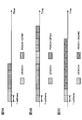
- FIG. 5 shows an example of the configuration of repeated transmission when the UE operates in extended coverage.
- the repeated transmission of the set predetermined number of times is also referred to as one set of repeated transmission.
- FIG. 5A shows an example when the packet size (TBS) is relatively small.
- TBS packet size
- FIG. 5B shows an example when the packet size (TBS) is relatively large. Also in this example, it is assumed that low MCS is used, and data (PDSCH) transmission is performed by QPSK modulation. In the case of FIG. 5B, four repetitive transmissions are set corresponding to QPSK. However, since the transmission data is large, it is necessary to perform multiple sets of one set of repeated transmissions. Since notification by EPDCCH occurs at every repeated transmission, the communication overhead increases as the data increases.
- Method 2 even in an environment where a low MCS is selected in the case of a conventional system, a larger MCS is intentionally selected to reduce overhead due to EPDCCH. In this case, in order to suppress a decrease in reception quality due to the use of a large MCS, the number of repetitions is also increased compared to a case where the packet size is relatively small.
- FIG. 5C shows an example of Method 2 when the packet size (TBS) is relatively large.
- TBS packet size
- a larger MCS (16QAM) and a larger number of repetitions (8 times) are adopted compared to FIG. 5B, and the overhead related to EPDCCH is reduced.
- FIG. 6 is a diagram illustrating an example of a correspondence relationship between the MCS and the repetition level when the UE operates in the extended coverage.
- the correspondence relationship (table) in FIG. 6 is configured such that the number of repetitions is the same and / or larger as the MCS index increases.
- the correspondence relationship in FIG. 6 is an example, and is not limited thereto.
- the correspondence is not only configured to have the same and / or larger number of iterations as the MCS index increases (or instead of), but the number of iterations is the same and / or larger as the TBS index increases. It can be constituted as follows.
- a high MCS level (and / or a high TBS level) is not normally used.
- the item of the relatively high MCS level in the conventional correspondence of FIG. 2 is deleted, and the item of the relatively low MCS level is set instead.
- a plurality of repetition numbers can be set for each set of modulation order and TBS index.
- repetition numbers 100 and 200 are set for MCS indexes 0 to 13 in FIG. 2, respectively.
- a device on the network side determines the number of repetitions of a signal to be transmitted and / or received by a predetermined modulation scheme (for example, QPSK) (step 1).
- the predetermined modulation scheme is preferably a modulation scheme having the smallest number of bits per symbol / subcarrier (corresponding to the smallest modulation order) among the selectable modulation schemes.
- This decision is preferably made in consideration of the coverage of the user terminal.
- the determination is preferably performed in consideration of measurement results (measurement reports) such as RSRP (Reference Signal Received Power), RSRQ (Reference Signal Received Quality), and channel state (CSI).
- measurement results such as RSRP (Reference Signal Received Power), RSRQ (Reference Signal Received Quality), and channel state (CSI).
- the apparatus selects a selection candidate (subset) of the correspondence relationship based on the number of repetitions of the predetermined modulation method determined in Step 1 (Step 2).
- Information on the selected subset is notified to the user terminal by higher layer signaling (for example, RRC signaling, MAC signaling, broadcast information (for example, SIB)).
- FIG. 7 is a diagram illustrating an example of a subset of the correspondence relationship between the MCS and the repetition level.
- three subsets are defined, and in each subset, the number of repetitions corresponding to the MCS index is defined. Note that the number of defined subsets is not limited to three. Moreover, as shown in FIG. 7, you may comprise so that the repetition number which overlaps in a some subset may be included.
- the information regarding the subset of the correspondence relationship between the MCS and the repetition level may be notified to the UE by broadcast information (for example, SIB), higher layer signaling (for example, RRC signaling), or may be set in advance. .
- broadcast information for example, SIB
- higher layer signaling for example, RRC signaling
- the correspondence relationship between the MCS and the repetition level may be the same or different between the uplink (for example, PUSCH) and the downlink (for example, PDSCH).
- the information regarding the correspondence relation between the MCS level and the repetition level can be configured to include information specifying which of the correspondence relation between the uplink and the downlink is shown.
- CQI is calculated based on the reception quality (eg, SINR) measured by the UE.
- SINR reception quality
- CQI table CQI table
- CQI is expressed by a modulation scheme, a coding rate, and frequency use efficiency. Since CQI corresponding to low SINR is considered to require repeated transmission in addition to a low modulation scheme, a lower coding rate and frequency utilization efficiency are newly added.
- the information related to the CQI table for coverage extension may be notified by broadcast information (for example, SIB), upper layer signaling (for example, RRC signaling) or the like, or may be set in advance by specifications. Good. Further, the radio base station and / or the user terminal may apply the CQI table for coverage extension only when it is determined as the coverage extension mode.
- broadcast information for example, SIB
- upper layer signaling for example, RRC signaling
- the first embodiment it is possible to eliminate the need for additional signaling when dynamically reporting the repetition level. Therefore, it is possible to suppress an increase in frequency utilization efficiency while preventing an increase in communication overhead. it can.
- the repetition level is explicitly set (notified). Specifically, the repetition level is dynamically set using a part of the fields of DCI. The correspondence between the repetition level included in the DCI and the actual number of repetitions is defined, and the UE grasps this in advance.
- the radio base station uses the broadcast information, the system information, the upper layer signaling (for example, RRC signaling) and the downlink control information, or a combination thereof, as information on the correspondence relationship between the repetition level and the repetition number.
- the terminal can be notified.
- the correspondence relationship may be common to all the cells or may be specified for each cell.
- the information regarding the said corresponding relationship is good also as a structure preset to a wireless base station and a user terminal.
- the eNB can dynamically determine the repetition level based on the channel state of the UE and the current MCS level (that is, the current TBS and allocated resources). Moreover, UE can acquire the number of repetitions based on the information regarding the notified repetition level.
- FIG. 8 is a diagram showing an example of the correspondence between the repetition level and the number of repetitions.
- FIG. 8 shows a repetition level (Repetition level) and a repetition number (Repetition number).
- the repetition level can be represented by a 3-bit bit string (000 to 111).
- the DCI including the repetition level is preferably included in, for example, a UL grant and a DL assignment that specify radio resources used for transmission / reception, but is not limited thereto.
- a new bit field that is not defined in the conventional LTE / LTE-A system may be used, or a notification may be made by replacing the existing bit field.
- a resource allocation (RA) field As an existing bit field, a resource allocation (RA) field, an MCS (Modulation and Coding Scheme) field, an HPN (HARQ Process Number) field, or the like can be used. Note that other fields may be read and used.
- RA resource allocation
- MCS Modulation and Coding Scheme
- HPN HARQ Process Number
- the RA field only needs to be able to specify a predetermined narrow band (for example, 6 RB) resource, and the bit amount can be reduced compared to the RA field in the existing system. For this reason, a part or all of the RA field of the existing system can be used as information on the repetition level.
- a predetermined narrow band for example, 6 RB
- the coverage extension mode when used in the MTC terminal (repetitive signal transmission is performed), it is considered that a part of the MCS (for example, a relatively high MCS) in the existing system is not selected. For this reason, a part or all of the MCS field of the existing system can be used as information regarding the repetition level.
- the normal terminal using FDD Frequency Division Duplex
- the normal terminal using TDD Time Division Duplex
- HARQ buffers or the maximum 16 HARQ buffers in a normal terminal using TDD (Time Division Duplex).
- TDD Time Division Duplex
- information regarding which field of DCI indicates the repetition level may be notified to the user terminal by higher layer signaling (for example, RRC signaling, broadcast information) or the like.
- higher layer signaling for example, RRC signaling, broadcast information
- FIG. 9 is a diagram illustrating an example of repeated transmission control according to the second embodiment.
- the radio base station eNB
- MTC UE user terminal
- the radio base station can dynamically specify an appropriate repetition level using DCI according to the transmission resource amount (TBS) allocated to the user terminal.
- TBS transmission resource amount allocated to the user terminal.
- the user terminal can determine the number of repetitions related to transmission using the repetition level included in the DCI.
- the repetition level can be notified to the UE by explicit notification, it is possible to suppress the UE process from being complicated. In addition, it is possible to suppress an increase in communication overhead by notifying the repetition level using a part or all of the existing DCI field.
- the correspondence between the repetition level and the number of repetitions shown in the second embodiment may be used in combination with the first embodiment.
- the correspondence relationship between the MCS and the repetition level in the first embodiment the correspondence relationship between the repetition level and the repetition number shown in the second embodiment is used to specify the repetition number indicated by the repetition level. May be.
- wireless communication system Wireless communication system
- wireless communication method which concerns on said each embodiment may each be applied independently, and may be applied in combination.
- an MTC terminal is illustrated as a user terminal whose use band is limited to a narrow band, but is not limited to an MTC terminal.
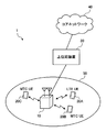
- FIG. 10 is a schematic configuration diagram of a wireless communication system according to an embodiment of the present invention.
- a wireless communication system 1 shown in FIG. 10 is an example in which an LTE system is adopted in a network domain of a machine communication system.
- carrier aggregation (CA) and / or dual connectivity (DC) in which a plurality of basic frequency blocks (component carriers) having the system bandwidth of the LTE system as one unit can be applied.
- the LTE system is assumed to be set to a maximum system bandwidth of 20 MHz for both downlink and uplink, but is not limited to this configuration.
- the wireless communication system 1 may be referred to as SUPER 3G, LTE-A (LTE-Advanced), IMT-Advanced, 4G, 5G, FRA (Future Radio Access), or the like.
- the wireless communication system 1 includes a wireless base station 10 and a plurality of user terminals 20A, 20B, and 20C that are wirelessly connected to the wireless base station 10.
- the radio base station 10 is connected to the higher station apparatus 30 and is connected to the core network 40 via the higher station apparatus 30.
- the upper station device 30 includes, for example, an access gateway device, a radio network controller (RNC), a mobility management entity (MME), and the like, but is not limited thereto.
- the plurality of user terminals 20 ⁇ / b> A, 20 ⁇ / b> B, and 20 ⁇ / b> C can communicate with the radio base station 10 in the cell 50.
- the user terminal 20A is a user terminal (hereinafter, LTE terminal) that supports LTE (up to Rel-10) or LTE-Advanced (including Rel-10 and later), and the other user terminals 20B and 20C are machine
- the MTC terminal is a communication device in the communication system.
- the user terminals 20 ⁇ / b> A, 20 ⁇ / b> B, and 20 ⁇ / b> C are simply referred to as the user terminal 20 unless it is necessary to distinguish between them.
- the MTC terminals 20B and 20C are terminals compatible with various communication systems such as LTE and LTE-A, and are not limited to fixed communication terminals such as electric meters, gas meters, and vending machines, but also mobile communication terminals such as vehicles. Good. Further, the user terminal 20 may communicate directly with another user terminal 20 or may communicate via the radio base station 10.
- OFDMA Orthogonal Frequency Division Multiple Access
- SC-FDMA Single Carrier Frequency Division Multiple Access
- OFDMA is a multi-carrier transmission scheme that performs communication by dividing a frequency band into a plurality of narrow frequency bands (subcarriers) and mapping data to each subcarrier.
- SC-FDMA is a single-carrier transmission scheme that reduces interference between terminals by dividing the system bandwidth into bands consisting of one or continuous resource blocks for each terminal and using a plurality of terminals with mutually different bands. is there.
- the uplink and downlink radio access methods are not limited to these combinations.
- downlink channels include a downlink shared channel (PDSCH) shared by each user terminal 20, a broadcast channel (PBCH: Physical Broadcast Channel), a downlink L1 / L2 control channel, and the like. Used. User data, higher layer control information, and predetermined SIB (System Information Block) are transmitted by PDSCH. Also, MIB (Master Information Block) is transmitted by PBCH.
- PDSCH downlink shared channel
- PBCH Physical Broadcast Channel
- SIB System Information Block
- Downlink L1 / L2 control channels include PDCCH (Physical Downlink Control Channel), EPDCCH (Enhanced Physical Downlink Control Channel), PCFICH (Physical Control Format Indicator Channel), PHICH (Physical Hybrid-ARQ Indicator Channel), and the like.
- Downlink control information (DCI: Downlink Control Information) including scheduling information of PDSCH and PUSCH is transmitted by PDCCH.
- the number of OFDM symbols used for PDCCH is transmitted by PCFICH.
- the HAICH transmission confirmation signal (ACK / NACK) for PUSCH is transmitted by PHICH.
- the EPDCCH is frequency-division multiplexed with the PDSCH, and is used for transmission of DCI and the like as with the PDCCH.
- an uplink shared channel (PUSCH: Physical Uplink Shared Channel), an uplink control channel (PUCCH: Physical Uplink Control Channel), and a random access channel (PRACH) shared by each user terminal 20 are used. Physical Random Access Channel) is used.
- PUSCH Physical Uplink Shared Channel
- PUCCH Physical Uplink Control Channel
- PRACH random access channel
- Physical Random Access Channel Physical Random Access Channel
- User data and higher layer control information are transmitted by PUSCH.
- downlink radio quality information (CQI: Channel Quality Indicator), a delivery confirmation signal, and the like are transmitted by PUCCH.
- a random access preamble for establishing connection with a cell is transmitted by the PRACH.
- FIG. 11 is a diagram illustrating an example of the overall configuration of a radio base station according to an embodiment of the present invention.
- the radio base station 10 includes a plurality of transmission / reception antennas 101, an amplifier unit 102, a transmission / reception unit 103, a baseband signal processing unit 104, a call processing unit 105, and a transmission path interface 106.
- User data transmitted from the radio base station 10 to the user terminal 20 via the downlink is input from the higher station apparatus 30 to the baseband signal processing unit 104 via the transmission path interface 106.
- PDCP Packet Data Convergence Protocol
- RLC Radio Link Control
- MAC Medium Access
- Retransmission control for example, HARQ (Hybrid Automatic Repeat reQuest) transmission processing
- HARQ Hybrid Automatic Repeat reQuest
- the downlink control signal is also subjected to transmission processing such as channel coding and inverse fast Fourier transform, and transferred to each transmitting / receiving unit 103.
- Each transmission / reception unit 103 converts the baseband signal output by precoding from the baseband signal processing unit 104 for each antenna to a radio frequency band and transmits the converted signal.
- the transmission / reception unit 103 can be configured by a transmitter / receiver, a transmission / reception circuit, or a transmission / reception device which is described based on common recognition in the technical field according to the present invention.
- the transmission / reception part 103 may be comprised as an integral transmission / reception part, and may be comprised from a transmission part and a receiving part.
- the radio frequency signal frequency-converted by the transmission / reception unit 103 is amplified by the amplifier unit 102 and transmitted from the transmission / reception antenna 101.
- the transmission / reception unit 103 can transmit and receive various signals with a narrow bandwidth (for example, 1.4 MHz) limited by the system bandwidth (for example, one component carrier).
- the transmission / reception unit 103 transmits DCI including information on the number of repetitions to the user terminal 20. Further, the transmission / reception unit 103 may transmit information regarding the correspondence between the MCS level and the repetition level, or information regarding the correspondence between the repetition level and the number of repetitions.
- the radio frequency signal received by each transmitting / receiving antenna 101 is amplified by the amplifier unit 102.
- Each transmitting / receiving unit 103 receives the upstream signal amplified by the amplifier unit 102.
- the transmission / reception unit 103 converts the frequency of the received signal into a baseband signal and outputs it to the baseband signal processing unit 104.
- the baseband signal processing unit 104 performs fast Fourier transform (FFT) processing, inverse discrete Fourier transform (IDFT: Inverse Discrete Fourier Transform) processing, and error correction on user data included in the input upstream signal.
- FFT fast Fourier transform
- IDFT inverse discrete Fourier transform
- Decoding, MAC retransmission control reception processing, RLC layer, and PDCP layer reception processing are performed and transferred to the upper station apparatus 30 via the transmission path interface 106.
- the call processing unit 105 performs call processing such as communication channel setting and release, state management of the radio base station 10, and radio resource management.
- the transmission path interface 106 transmits and receives signals to and from the higher station apparatus 30 via a predetermined interface.
- the transmission path interface 106 transmits and receives (backhaul signaling) signals to and from the adjacent radio base station 10 via an interface between base stations (for example, an optical fiber compliant with CPRI (Common Public Radio Interface), X2 interface). Also good.
- CPRI Common Public Radio Interface
- X2 interface also good.
- FIG. 12 is a diagram illustrating an example of a functional configuration of the radio base station according to the present embodiment. Note that FIG. 12 mainly shows functional blocks of characteristic portions in the present embodiment, and the wireless base station 10 also has other functional blocks necessary for wireless communication.
- the baseband signal processing unit 104 includes a control unit (scheduler) 301, a transmission signal generation unit (generation unit) 302, a mapping unit 303, a reception signal processing unit 304, and a measurement unit 305. It is equipped with.
- the control unit (scheduler) 301 controls the entire radio base station 10.
- the control part 301 can be comprised from the controller, the control circuit, or control apparatus demonstrated based on the common recognition in the technical field which concerns on this invention.
- the control unit 301 controls signal generation by the transmission signal generation unit 302 and signal allocation by the mapping unit 303, for example.
- the control unit 301 also controls signal reception processing by the reception signal processing unit 304 and signal measurement by the measurement unit 305.
- the control unit 301 controls scheduling (for example, resource allocation) of system information, a downlink data signal transmitted on the PDSCH, and a downlink control signal transmitted on the PDCCH and / or EPDCCH. It also controls scheduling of synchronization signals and downlink reference signals such as CRS (Cell-specific Reference Signal), CSI-RS (Channel State Information Reference Signal), DM-RS (Demodulation Reference Signal).
- CRS Cell-specific Reference Signal
- CSI-RS Channel State Information Reference Signal
- DM-RS Demodulation Reference Signal
- the control unit 301 also transmits an uplink data signal transmitted on the PUSCH, an uplink control signal transmitted on the PUCCH and / or PUSCH (for example, a delivery confirmation signal (HARQ-ACK)), a random access preamble transmitted on the PRACH, Controls scheduling of uplink reference signals and the like.
- an uplink data signal transmitted on the PUSCH for example, an uplink control signal transmitted on the PUCCH and / or PUSCH (for example, a delivery confirmation signal (HARQ-ACK)), a random access preamble transmitted on the PRACH, Controls scheduling of uplink reference signals and the like.
- HARQ-ACK delivery confirmation signal
- the control unit 301 controls the transmission signal generation unit 302 and the mapping unit 303 so that various signals are allocated to a narrow band and transmitted to the user terminal 20.
- the control unit 301 performs control so that downlink broadcast information (MIB, SIB), EPDCCH, PDSCH, and the like are transmitted in a narrow band.
- MIB downlink broadcast information
- SIB downlink broadcast information
- control unit 301 controls (sets, etc.) the number of repetitions applied to the transmission signal and / or reception signal of the predetermined user terminal 20.
- control unit 301 controls the user terminal 20 to notify the information regarding the number of repetitions by DCI.
- control unit 301 determines information on the number of repetitions in association with the MCS applied to the signal.
- the control unit 301 notifies the user terminal 20 of information regarding the determined number of repetitions. Specifically, the control unit 301 may implicitly notify the user terminal 20 of information regarding the determined number of repetitions by notification of the MCS index (first embodiment). In this case, the control unit 301 uses broadcast information (MIB, SIB), higher layer signaling (for example, RRC signaling), etc., for information regarding the correspondence (table) between the MCS level (for example, MCS index) and the repetition level. The user terminal 20 may be notified.
- broadcast information MIB, SIB
- higher layer signaling for example, RRC signaling
- the control unit 301 may individually have a correspondence (table) for the normal coverage mode and a correspondence (table) for the extended coverage mode.
- the table for the normal coverage mode is preferably configured so that the number of repetitions is the same and / or decreases as the MCS index increases (method 1 of the first embodiment).
- the extended coverage mode table is preferably configured so that the number of repetitions is the same and / or larger when the MCS index (and / or TBS index) is increased (method 2 in the first embodiment).
- the control unit 301 can determine the above-mentioned table in consideration of the coverage based on the measurement report from the user terminal. For example, the control unit 301 may select a table for extended coverage mode from table candidates (subsets). In this case, the control unit 301 may notify the user terminal 20 of table selection information for selecting a table to be used from the subset.
- the control unit 301 may notify the user terminal 20 of information related to these tables (table reconfiguration information and information related to subsets).
- control unit 301 may explicitly notify the user terminal 20 of information regarding the determined number of repetitions using a partial field of DCI (second embodiment).
- the control unit 301 may notify the user terminal 20 of information regarding the correspondence (table) between the repetition level (index) and the number of repetitions for notification by DCI, for example, by broadcast information.
- control unit 301 displays information indicating that the user terminal 20 operates in a mode that supports normal coverage (normal coverage mode) or a mode that supports coverage extension (coverage extended mode), as broadcast information, Notification may be performed using layer signaling, downlink control information, or the like.
- the control unit 301 outputs the number of repetitions applied to each user terminal 20, information about the MCS level, and the like to the received signal processing unit 304.
- the transmission signal generation unit (generation unit) 302 generates a downlink signal (downlink control signal, downlink data signal, downlink reference signal, etc.) based on an instruction from the control unit 301, and outputs it to the mapping unit 303.
- the transmission signal generation unit 302 can be configured by a signal generator, a signal generation circuit, or a signal generation device described based on common recognition in the technical field according to the present invention.
- the transmission signal generation unit 302 generates, for example, a DL assignment that notifies downlink signal allocation information and a UL grant that notifies uplink signal allocation information based on an instruction from the control unit 301. Further, the downlink data signal is subjected to coding processing and modulation processing according to a coding rate, a modulation scheme, and the like determined based on channel state information (CSI) from each user terminal 20.
- CSI channel state information
- the transmission signal generation unit 302 when the downlink signal repetitive transmission (for example, PDSCH repetitive transmission) is set, the transmission signal generation unit 302 generates the same downlink signal over a plurality of subframes and outputs the same to the mapping unit 303.
- the downlink signal repetitive transmission for example, PDSCH repetitive transmission
- the transmission signal generation unit 302 generates DCI including information regarding the number of repetitions based on an instruction from the control unit 301 and outputs the DCI to the mapping unit 303.
- the mapping unit 303 maps the downlink signal generated by the transmission signal generation unit 302 to a predetermined narrowband radio resource (for example, a maximum of 6 resource blocks) based on an instruction from the control unit 301, and transmits and receives To 103.
- the mapping unit 303 can be configured by a mapper, a mapping circuit, or a mapping device described based on common recognition in the technical field according to the present invention.
- the reception signal processing unit 304 performs reception processing (for example, demapping, demodulation, decoding, etc.) on the reception signal input from the transmission / reception unit 103.
- the received signal is, for example, an uplink signal (uplink control signal, uplink data signal, uplink reference signal, etc.) transmitted from the user terminal 20.
- the reception signal processing unit 304 can be configured by a signal processor, a signal processing circuit, or a signal processing device described based on common recognition in the technical field according to the present invention.
- the reception signal processing unit 304 applies reception processing for the repetitive signal to the reception signal from the user terminal 20 that transmits the repetitive signal.
- Reception signal processing section 304 outputs information decoded by the reception processing to control section 301.
- the reception signal processing unit 304 outputs the reception signal and the signal after reception processing to the measurement unit 305.
- the measurement unit 305 performs measurement on the received signal.
- the measurement part 305 can be comprised from the measuring device, measurement circuit, or measurement apparatus demonstrated based on common recognition in the technical field which concerns on this invention.
- the measurement unit 305 may measure, for example, received power (for example, RSRP (Reference Signal Received Power)), reception quality (for example, RSRQ (Reference Signal Received Quality)), channel state, and the like of the received signal.
- the measurement result may be output to the control unit 301.
- FIG. 13 is a diagram illustrating an example of the overall configuration of the user terminal according to the present embodiment.
- the user terminal 20 includes a transmission / reception antenna 201, an amplifier unit 202, a transmission / reception unit 203, a baseband signal processing unit 204, and an application unit 205.
- the user terminal 20 may include a plurality of transmission / reception antennas 201, an amplifier unit 202, a transmission / reception unit 203, and the like.
- the radio frequency signal received by the transmission / reception antenna 201 is amplified by the amplifier unit 202.
- the transmission / reception unit 203 receives the downlink signal amplified by the amplifier unit 202.
- the transmission / reception unit 203 receives DCI including information regarding the number of repetitions.
- the transmission / reception unit 203 converts the frequency of the received signal into a baseband signal and outputs it to the baseband signal processing unit 204.
- the transmission / reception unit 203 can be configured by a transmitter / receiver, a transmission / reception circuit, or a transmission / reception device described based on common recognition in the technical field according to the present invention.
- the transmission / reception unit 203 may be configured as an integral transmission / reception unit, or may be configured from a transmission unit and a reception unit.
- the baseband signal processing unit 204 performs FFT processing, error correction decoding, retransmission control reception processing, and the like on the input baseband signal.
- the downlink user data is transferred to the application unit 205.
- the application unit 205 performs processing related to layers higher than the physical layer and the MAC layer.
- broadcast information in the downlink data is also transferred to the application unit 205.
- uplink user data is input from the application unit 205 to the baseband signal processing unit 204.
- the baseband signal processing unit 204 performs transmission / reception by performing retransmission control transmission processing (for example, HARQ transmission processing), channel coding, precoding, discrete Fourier transform (DFT) processing, IFFT processing, and the like. Is transferred to the unit 203.
- the transmission / reception unit 203 converts the baseband signal output from the baseband signal processing unit 204 into a radio frequency band and transmits it.
- the radio frequency signal frequency-converted by the transmission / reception unit 203 is amplified by the amplifier unit 202 and transmitted from the transmission / reception antenna 201.
- FIG. 14 is a diagram illustrating an example of a functional configuration of the user terminal according to the present embodiment.
- FIG. 14 mainly shows functional blocks of characteristic portions in the present embodiment, and the user terminal 20 also has other functional blocks necessary for wireless communication.
- the baseband signal processing unit 204 included in the user terminal 20 includes a control unit 401, a transmission signal generation unit (generation unit) 402, a mapping unit 403, a reception signal processing unit 404, and a measurement unit. 405.
- the control unit 401 controls the entire user terminal 20.
- the control unit 401 can be composed of a controller, a control circuit, or a control device described based on common recognition in the technical field according to the present invention.
- the control unit 401 controls, for example, signal generation by the transmission signal generation unit 402 and signal allocation by the mapping unit 403.
- the control unit 401 controls signal reception processing by the reception signal processing unit 404 and signal measurement by the measurement unit 405.
- the control unit 401 obtains, from the received signal processing unit 404, a downlink control signal (a signal transmitted by PDCCH / EPDCCH) and a downlink data signal (a signal transmitted by PDSCH) transmitted from the radio base station 10.
- the control unit 401 generates an uplink control signal (for example, an acknowledgment signal (HARQ-ACK)) or an uplink data signal based on a downlink control signal, a result of determining whether retransmission control is necessary for the downlink data signal, or the like.
- HARQ-ACK acknowledgment signal
- control unit 401 is identical based on the information regarding the number of repetitions received from the radio base station 10. Control is performed so that a signal including information is repeatedly transmitted over a plurality of subframes.
- the control unit 401 can determine the mode of the own terminal based on the information. Further, the control unit 401 may determine the mode based on information regarding the number of repetitions.
- the control unit 401 determines the number of repetitions related to transmission and / or reception of a predetermined signal based on information regarding the number of repetitions included in the DCI transmitted from the radio base station 10. Then, the control unit 401 controls the transmission signal generation unit 402 and the mapping unit 403 using the repetition number related to the transmission signal, and controls the reception signal processing unit 404 and the measurement unit 405 using the repetition number related to the reception signal.
- the control unit 401 refers to the correspondence (table) between the MCS level and the repetition level, and determines the number of repetitions of the signal according to the MCS index based on the MCS index input from the reception signal processing unit 404.
- Good (first embodiment).
- the control unit 401 may refer to a different table depending on the coverage mode.
- the control unit 401 may determine a table to be used based on table reconstruction information, table selection information, and the like.
- control unit 401 refers to the correspondence relationship (table) between the repetition level and the repetition number, and based on a predetermined field included in the DCI input from the reception signal processing unit 404, the repetition number of the predetermined signal. May be determined (second embodiment).
- control unit 401 may output information on the number of repetitions to the reception signal processing unit 404 and perform reception processing based on the information.
- the transmission signal generation unit 402 generates an uplink signal (uplink control signal, uplink data signal, uplink reference signal, etc.) based on an instruction from the control unit 401 and outputs the uplink signal to the mapping unit 403.
- the transmission signal generation unit 402 can be configured by a signal generator, a signal generation circuit, or a signal generation device described based on common recognition in the technical field according to the present invention.
- the transmission signal generation unit 402 generates an uplink control signal related to a delivery confirmation signal (HARQ-ACK) or channel state information (CSI) based on an instruction from the control unit 401, for example.
- the transmission signal generation unit 402 generates an uplink data signal based on an instruction from the control unit 401.
- the transmission signal generation unit 402 is instructed by the control unit 401 to generate an uplink data signal when the UL grant is included in the downlink control signal notified from the radio base station 10.
- the transmission signal generation unit 402 generates the same uplink signal over a plurality of subframes and outputs it to the mapping unit 403 when the user terminal 20 is configured to repeatedly transmit a predetermined uplink signal.
- the number of repetitions may be set based on an instruction from the control unit 401.
- the mapping unit 403 Based on an instruction from the control unit 401, the mapping unit 403 maps the uplink signal generated by the transmission signal generation unit 402 to a radio resource (for example, a maximum of 6 resource blocks) and outputs the radio signal to the transmission / reception unit 203.
- the mapping unit 403 can be configured by a mapper, a mapping circuit, or a mapping device described based on common recognition in the technical field according to the present invention.
- the reception signal processing unit 404 performs reception processing (for example, demapping, demodulation, decoding, etc.) on the reception signal input from the transmission / reception unit 203.
- the received signal is, for example, a downlink signal (downlink control signal, downlink data signal, downlink reference signal, etc.) transmitted from the radio base station 10.
- the reception signal processing unit 404 can be configured by a signal processor, a signal processing circuit, or a signal processing device described based on common recognition in the technical field according to the present invention.
- the reception signal processing unit 404 applies reception processing for the repetitive signal to the reception signal from the radio base station 10 that transmits the repetitive signal.
- Reception signal processing section 404 outputs information decoded by the reception processing to control section 401.
- the reception signal processing unit 404 outputs broadcast information, system information, RRC signaling, DCI, and the like to the control unit 401, for example.
- the reception signal processing unit 404 outputs the reception signal and the signal after reception processing to the measurement unit 405.
- the measurement unit 405 performs measurement on the received signal.
- the measurement part 405 can be comprised from the measuring device, measurement circuit, or measurement apparatus demonstrated based on common recognition in the technical field which concerns on this invention.
- the measurement unit 405 may measure, for example, the received power (for example, RSRP), reception quality (for example, RSRQ), channel state, and the like of the received signal.
- the measurement result may be output to the control unit 401.
- each functional block is realized by one physically coupled device, or may be realized by two or more physically separated devices connected by wire or wirelessly and by a plurality of these devices. Good.
- the radio base station 10 and the user terminal 20 are realized using hardware such as ASIC (Application Specific Integrated Circuit), PLD (Programmable Logic Device), and FPGA (Field Programmable Gate Array). May be.
- the radio base station 10 and the user terminal 20 are each a computer device including a processor (CPU: Central Processing Unit), a communication interface for network connection, a memory, and a computer-readable storage medium holding a program. It may be realized. That is, the radio base station, user terminal, and the like according to an embodiment of the present invention may function as a computer that performs processing of the radio communication method according to the present invention.
- Computer-readable recording media include, for example, flexible disks, magneto-optical disks, ROM (Read Only Memory), EPROM (Erasable Programmable ROM), CD-ROM (Compact Disc-ROM), RAM (Random Access Memory), A storage medium such as a hard disk.
- the program may be transmitted from a network via a telecommunication line.
- the radio base station 10 and the user terminal 20 may include an input device such as an input key and an output device such as a display.
- the functional configurations of the radio base station 10 and the user terminal 20 may be realized by the hardware described above, may be realized by a software module executed by a processor, or may be realized by a combination of both.
- the processor controls the entire user terminal by operating an operating system. Further, the processor reads programs, software modules and data from the storage medium into the memory, and executes various processes according to these.
- the program may be a program that causes a computer to execute the operations described in the above embodiments.
- the control unit 401 of the user terminal 20 may be realized by a control program stored in a memory and operated by a processor, and may be realized similarly for other functional blocks.
Abstract
Description
第1の実施形態では、繰り返しレベルを、暗黙的に設定(通知)する。具体的には、異なるチャネル状態下におけるMCSレベルと繰り返しレベルとの対応関係を規定しておき、予めUEがこれを把握する。
UEが通常カバレッジで動作する場合、MCSが高くなるほど繰り返し数が低下する(又は繰り返ししない)ように設定し、MCSが低くなるほど繰り返し数が増加するように設定する。
UEが拡張カバレッジで動作する場合、方法1とは逆に、MCSが低くなるほど繰り返し数が低下するように設定し、MCSが高くなるほど繰り返し数が増加するように設定する。例えば、QPSKには繰り返し数100が対応し、16QAMには繰り返し数150が対応するように構成する。
第2の実施形態では、繰り返しレベルを、明示的に設定(通知)する。具体的には、DCIの一部のフィールドを用いて繰り返しレベルを動的に設定する。DCIに含まれる繰り返しレベルと実際の繰り返し数との対応関係を規定しておき、予めUEがこれを把握する。
以下、本発明の一実施形態に係る無線通信システムの構成について説明する。この無線通信システムでは、上述した本発明の実施形態に係る無線通信方法が適用される。なお、上記の各実施形態に係る無線通信方法は、それぞれ単独で適用されてもよいし、組み合わせて適用されてもよい。ここでは、狭帯域に使用帯域が制限されたユーザ端末としてMTC端末を例示するが、MTC端末に限定されるものではない。
図11は、本発明の一実施形態に係る無線基地局の全体構成の一例を示す図である。無線基地局10は、複数の送受信アンテナ101と、アンプ部102と、送受信部103と、ベースバンド信号処理部104と、呼処理部105と、伝送路インターフェース106と、を備えている。
図13は、本実施形態に係るユーザ端末の全体構成の一例を示す図である。なお、ここでは詳細な説明を省略するが、通常のLTE端末がMTC端末として振る舞うように動作してもよい。ユーザ端末20は、送受信アンテナ201と、アンプ部202と、送受信部203と、ベースバンド信号処理部204と、アプリケーション部205と、を備えている。また、ユーザ端末20は、送受信アンテナ201、アンプ部202、送受信部203などを複数備えてもよい。
Claims (10)
- システム帯域の一部の狭帯域に使用帯域が制限されたユーザ端末であって、
繰り返し数に関する情報を含む下り制御情報(DCI:Downlink Control Information)を受信する受信部と、
前記繰り返し数に関する情報に基づいて、所定の信号の送信及び/又は受信に関する繰り返し数を判断する制御部と、を有し、
前記繰り返し数に関する情報は、前記所定の信号に適用されるMCS(Modulation and Coding Scheme)に関連付けて決定されることを特徴とするユーザ端末。 - 前記繰り返し数に関する情報は、MCSインデックスであることを特徴とする請求項1に記載のユーザ端末。
- 前記制御部は、通常カバレッジモードにおいて、MCSインデックスが増加すると繰り返し数が同じ又は小さくなるように構成された第1のテーブルに基づいて、繰り返し数を判断することを特徴とする請求項2に記載のユーザ端末。
- 前記制御部は、拡張カバレッジモードにおいて、MCSインデックスが増加すると繰り返し数が同じ又は大きくなるように構成された第2のテーブルに基づいて、繰り返し数を判断することを特徴とする請求項2又は請求項3に記載のユーザ端末。
- 前記第2のテーブルは、さらにTBS(Transport Block Size)インデックスが増加すると繰り返し数が同じ又は大きくなるように構成されたことを特徴とする請求項4に記載のユーザ端末。
- 前記受信部は、前記第2のテーブルを複数の候補から選択するためのテーブル選択情報をさらに受信し、
前記制御部は、前記テーブル選択情報に基づいて、前記第2のテーブルを選択することを特徴とする請求項4又は請求項5に記載のユーザ端末。 - 前記繰り返し数に関する情報は、既存システムで規定されるDCIの所定のフィールドの一部又は全部で示されるインデックスであり、
前記受信部は、当該インデックスと繰り返し数との対応関係に関する情報をさらに受信することを特徴とする請求項1に記載のユーザ端末。 - 前記所定のフィールドは、リソース割り当てフィールド、MCSフィールド、HPN(HARQ Process Number)フィールドのいずれかであることを特徴とする請求項7に記載のユーザ端末。
- システム帯域の一部の狭帯域に使用帯域が制限されたユーザ端末と通信する無線基地局であって、
所定の信号の送信及び/又は受信に関する繰り返し数を制御する制御部と、
繰り返し数に関する情報を含む下り制御情報(DCI:Downlink Control Information)を生成する生成部と、
前記ユーザ端末に前記DCIを送信する送信部と、を有し、
前記生成部は、前記繰り返し数に関する情報を、前記所定の信号に適用されるMCS(Modulation and Coding Scheme)に関連付けて生成することを特徴とする無線基地局。 - システム帯域の一部の狭帯域に使用帯域が制限されたユーザ端末と無線基地局が通信する無線通信方法であって、
前記ユーザ端末において、繰り返し数に関する情報を含む下り制御情報(DCI:Downlink Control Information)を受信する工程と、
前記繰り返し数に関する情報に基づいて、所定の信号の送信及び/又は受信に関する繰り返し数を判断する工程と、を有し、
前記繰り返し数に関する情報は、前記所定の信号に適用されるMCS(Modulation and Coding Scheme)に関連付けて決定されることを特徴とする無線通信方法。
Priority Applications (3)
| Application Number | Priority Date | Filing Date | Title |
|---|---|---|---|
| JP2017511081A JP6725497B2 (ja) | 2015-04-09 | 2016-04-08 | ユーザ端末、無線基地局及び無線通信方法 |
| CN201680020788.XA CN107431507A (zh) | 2015-04-09 | 2016-04-08 | 用户终端、无线基站以及无线通信方法 |
| US15/564,762 US20180115387A1 (en) | 2015-04-09 | 2016-04-08 | User terminal, radio base station and radio communication method |
Applications Claiming Priority (2)
| Application Number | Priority Date | Filing Date | Title |
|---|---|---|---|
| JP2015080322 | 2015-04-09 | ||
| JP2015-080322 | 2015-04-09 |
Publications (1)
| Publication Number | Publication Date |
|---|---|
| WO2016163502A1 true WO2016163502A1 (ja) | 2016-10-13 |
Family
ID=57071897
Family Applications (1)
| Application Number | Title | Priority Date | Filing Date |
|---|---|---|---|
| PCT/JP2016/061495 WO2016163502A1 (ja) | 2015-04-09 | 2016-04-08 | ユーザ端末、無線基地局及び無線通信方法 |
Country Status (4)
| Country | Link |
|---|---|
| US (1) | US20180115387A1 (ja) |
| JP (1) | JP6725497B2 (ja) |
| CN (1) | CN107431507A (ja) |
| WO (1) | WO2016163502A1 (ja) |
Cited By (5)
| Publication number | Priority date | Publication date | Assignee | Title |
|---|---|---|---|---|
| JP2018117180A (ja) * | 2017-01-16 | 2018-07-26 | ソフトバンク株式会社 | 通信端末装置、基地局及び通信網側装置 |
| WO2018173225A1 (ja) * | 2017-03-23 | 2018-09-27 | 富士通株式会社 | 端末装置、基地局装置、無線通信システム及び無線通信方法 |
| CN109257819A (zh) * | 2017-07-13 | 2019-01-22 | 普天信息技术有限公司 | 一种多子带启动dci的指示方法、基站及用户设备 |
| JP2020533867A (ja) * | 2017-09-08 | 2020-11-19 | エイ・ティ・アンド・ティ インテレクチュアル プロパティ アイ,エル.ピー. | 5gネットワーク又は他の次世代ネットワークのフィードバックデータを送信する繰り返し因数の構成 |
| WO2022079861A1 (ja) * | 2020-10-15 | 2022-04-21 | 株式会社Nttドコモ | 端末 |
Families Citing this family (15)
| Publication number | Priority date | Publication date | Assignee | Title |
|---|---|---|---|---|
| US10425938B2 (en) * | 2015-11-06 | 2019-09-24 | Kt Corporation | Method of determining modulation order and transport block size in downlink data channel, and apparatus thereof |
| WO2018027913A1 (zh) * | 2016-08-12 | 2018-02-15 | 华为技术有限公司 | 一种切换信号传输模式的方法、基站及终端设备 |
| CN107888333B (zh) * | 2016-09-30 | 2020-12-08 | 株式会社Kt | 经由用于覆盖扩展的上行链路信道收发数据的方法及其装置 |
| AR112548A1 (es) * | 2017-06-30 | 2019-11-13 | Ericsson Telefon Ab L M | Método y aparato para detección de interferencias e informe en una red de comunicación inalámbrica |
| CN111684743B (zh) * | 2018-02-13 | 2021-12-14 | 华为技术有限公司 | 上行信号的发送方法、接收方法、通信设备及网络设备 |
| CN112262609A (zh) * | 2018-04-16 | 2021-01-22 | 株式会社Ntt都科摩 | 用户终端以及无线基站 |
| US20190327064A1 (en) * | 2018-04-19 | 2019-10-24 | Qualcomm Incorporated | Repetition-based transmissions for uplink ultra-reliable low latency communication |
| WO2020003522A1 (ja) * | 2018-06-29 | 2020-01-02 | 株式会社Nttドコモ | ユーザ端末 |
| CN110830161B (zh) * | 2018-08-10 | 2021-01-12 | 华为技术有限公司 | 一种确定传输块大小的方法及装置 |
| WO2020035955A1 (ja) * | 2018-08-17 | 2020-02-20 | 株式会社Nttドコモ | ユーザ端末および無線通信方法 |
| CN111224745B (zh) * | 2018-11-26 | 2023-03-28 | 中国电信股份有限公司 | 窄带物联网NB-IoT网络资源分配方法、终端、设备和系统 |
| WO2020164140A1 (zh) * | 2019-02-15 | 2020-08-20 | 华为技术有限公司 | 通信方法和装置 |
| CN114041302A (zh) * | 2019-04-26 | 2022-02-11 | 株式会社Ntt都科摩 | 用户终端以及无线通信方法 |
| US11451934B2 (en) * | 2019-07-25 | 2022-09-20 | Qualcomm Incorporated | Transport block size and rate matching for multicast communications |
| US11627569B2 (en) * | 2019-12-17 | 2023-04-11 | Qualcomm Incorporated | Dynamic uplink transmission adaptation |
Citations (1)
| Publication number | Priority date | Publication date | Assignee | Title |
|---|---|---|---|---|
| WO2014109566A1 (ko) * | 2013-01-09 | 2014-07-17 | 엘지전자 주식회사 | 신호 수신 방법 및 사용자기기와 신호 전송 방법 및 기지국 |
Family Cites Families (5)
| Publication number | Priority date | Publication date | Assignee | Title |
|---|---|---|---|---|
| US10111224B2 (en) * | 2011-09-30 | 2018-10-23 | Interdigital Patent Holdings, Inc. | Device communication using a reduced channel bandwidth |
| EP2635082A1 (en) * | 2012-02-29 | 2013-09-04 | Panasonic Corporation | Dynamic subframe bundling |
| CN103384187B (zh) * | 2012-05-04 | 2017-04-12 | 中国电信股份有限公司 | Tti绑定的上行传输方法、系统与移动终端 |
| US9398548B2 (en) * | 2012-10-26 | 2016-07-19 | Lg Electronics Inc. | Interference control method in wireless communication system and apparatus for the same |
| US11291051B2 (en) * | 2013-09-27 | 2022-03-29 | Nokia Technologies Oy | Methods and devices for random access |
-
2016
- 2016-04-08 US US15/564,762 patent/US20180115387A1/en not_active Abandoned
- 2016-04-08 JP JP2017511081A patent/JP6725497B2/ja not_active Expired - Fee Related
- 2016-04-08 CN CN201680020788.XA patent/CN107431507A/zh active Pending
- 2016-04-08 WO PCT/JP2016/061495 patent/WO2016163502A1/ja active Application Filing
Patent Citations (1)
| Publication number | Priority date | Publication date | Assignee | Title |
|---|---|---|---|---|
| WO2014109566A1 (ko) * | 2013-01-09 | 2014-07-17 | 엘지전자 주식회사 | 신호 수신 방법 및 사용자기기와 신호 전송 방법 및 기지국 |
Non-Patent Citations (4)
| Title |
|---|
| ALCATEL -LUCENT ET AL.: "Considerations for PDSCH/PUSCH and the Physical Downlink Control Channels for LC- MTC", 3GPP TSG-RAN WG1#80, RL-150128, vol. 2.2, XP050933342, Retrieved from the Internet <URL:http://www.3gpp.org/ftp/tsg_ran/WG1_RL1/TSGR1_80/Docs/Rl-150128.zip> * |
| NSN ET AL.: "Data Channel Coverage Enhancement", 3GPP TSG-RAN WG1#75, R1-135576, 11 November 2013 (2013-11-11), XP050735241, Retrieved from the Internet <URL:http://www.3gpp.org/ftp/tsg-ran/WG1_RL1/TSGR1_75/Docs/R1-135576.zip> * |
| NTT DOCOMO: "Views on SIB design in Rel-13 Low Cost MTC [ online", 3GPP TSG-RAN WG1#80, R1- 150535, 9 February 2015 (2015-02-09), XP050933743, Retrieved from the Internet <URL:http://www.3gpp.org/ftp/tsg_ran/WG1_RL1/TSGR1_80/Docs/R1-150535.zip> * |
| ZTE: "Capacity evaluation for in-band operation", 3GPP TSG-RAN WG1#83, RL-156624, 15 November 2015 (2015-11-15), XP051003028, Retrieved from the Internet <URL:http://www.3gpp.org/ftp/tsg_ran/WG1_RL1/TSGR1_83/Docs/R1-156624.zip> * |
Cited By (7)
| Publication number | Priority date | Publication date | Assignee | Title |
|---|---|---|---|---|
| JP2018117180A (ja) * | 2017-01-16 | 2018-07-26 | ソフトバンク株式会社 | 通信端末装置、基地局及び通信網側装置 |
| WO2018173225A1 (ja) * | 2017-03-23 | 2018-09-27 | 富士通株式会社 | 端末装置、基地局装置、無線通信システム及び無線通信方法 |
| CN109257819A (zh) * | 2017-07-13 | 2019-01-22 | 普天信息技术有限公司 | 一种多子带启动dci的指示方法、基站及用户设备 |
| JP2020533867A (ja) * | 2017-09-08 | 2020-11-19 | エイ・ティ・アンド・ティ インテレクチュアル プロパティ アイ,エル.ピー. | 5gネットワーク又は他の次世代ネットワークのフィードバックデータを送信する繰り返し因数の構成 |
| US11095400B2 (en) | 2017-09-08 | 2021-08-17 | At&T Intellectual Property I, L.P. | Configuration of repetition factors for transmitting feedback data for 5G or other next generation network |
| JP7034262B2 (ja) | 2017-09-08 | 2022-03-11 | エイ・ティ・アンド・ティ インテレクチュアル プロパティ アイ,エル.ピー. | 5gネットワーク又は他の次世代ネットワークのフィードバックデータを送信する繰り返し因数の構成 |
| WO2022079861A1 (ja) * | 2020-10-15 | 2022-04-21 | 株式会社Nttドコモ | 端末 |
Also Published As
| Publication number | Publication date |
|---|---|
| US20180115387A1 (en) | 2018-04-26 |
| JP6725497B2 (ja) | 2020-07-22 |
| JPWO2016163502A1 (ja) | 2018-03-22 |
| CN107431507A (zh) | 2017-12-01 |
Similar Documents
| Publication | Publication Date | Title |
|---|---|---|
| JP6725497B2 (ja) | ユーザ端末、無線基地局及び無線通信方法 | |
| US10455579B2 (en) | User terminal, radio base station, and radio communication method | |
| WO2016072257A1 (ja) | ユーザ端末、無線基地局及び無線通信方法 | |
| JP6472463B2 (ja) | 無線基地局、ユーザ端末及び無線通信方法 | |
| WO2016182052A1 (ja) | ユーザ端末、無線基地局及び無線通信方法 | |
| JP6779212B2 (ja) | ユーザ端末、無線基地局及び無線通信方法 | |
| WO2017078128A1 (ja) | ユーザ端末、無線基地局及び無線通信方法 | |
| CN107211412B (zh) | 终端、基站以及无线通信方法 | |
| JP6777627B2 (ja) | 無線基地局、ユーザ端末及び無線通信方法 | |
| JP6042505B1 (ja) | ユーザ端末、無線基地局及び無線通信方法 | |
| JP6105672B2 (ja) | ユーザ端末及び無線通信方法 | |
| WO2017026513A1 (ja) | ユーザ端末、無線基地局、無線通信方法及び無線通信システム | |
| WO2016182050A1 (ja) | ユーザ端末、無線基地局、無線通信システム及び無線通信方法 | |
| JP6153574B2 (ja) | ユーザ端末、無線基地局及び無線通信方法 | |
| CN112753239A (zh) | 用户终端 | |
| CN107211420B (zh) | 用户终端、无线基站、无线通信系统以及无线通信方法 | |
| WO2016121776A1 (ja) | ユーザ端末および無線通信方法 | |
| WO2017026548A1 (ja) | ユーザ端末、無線基地局及び無線通信方法 | |
| US8983485B2 (en) | Base station apparatus, mobile terminal apparatus and scheduling method | |
| WO2016163501A1 (ja) | ユーザ端末、無線基地局及び無線通信方法 |
Legal Events
| Date | Code | Title | Description |
|---|---|---|---|
| 121 | Ep: the epo has been informed by wipo that ep was designated in this application |
Ref document number: 16776668 Country of ref document: EP Kind code of ref document: A1 |
|
| ENP | Entry into the national phase |
Ref document number: 2017511081 Country of ref document: JP Kind code of ref document: A |
|
| WWE | Wipo information: entry into national phase |
Ref document number: 15564762 Country of ref document: US |
|
| NENP | Non-entry into the national phase |
Ref country code: DE |
|
| 122 | Ep: pct application non-entry in european phase |
Ref document number: 16776668 Country of ref document: EP Kind code of ref document: A1 |