WO2016163476A1 - ユーザ端末及び制御方法 - Google Patents
ユーザ端末及び制御方法 Download PDFInfo
- Publication number
- WO2016163476A1 WO2016163476A1 PCT/JP2016/061436 JP2016061436W WO2016163476A1 WO 2016163476 A1 WO2016163476 A1 WO 2016163476A1 JP 2016061436 W JP2016061436 W JP 2016061436W WO 2016163476 A1 WO2016163476 A1 WO 2016163476A1
- Authority
- WO
- WIPO (PCT)
- Prior art keywords
- data
- user terminal
- communication
- mac
- field
- Prior art date
Links
Images


Classifications
-
- H—ELECTRICITY
- H04—ELECTRIC COMMUNICATION TECHNIQUE
- H04W—WIRELESS COMMUNICATION NETWORKS
- H04W8/00—Network data management
- H04W8/005—Discovery of network devices, e.g. terminals
-
- H—ELECTRICITY
- H04—ELECTRIC COMMUNICATION TECHNIQUE
- H04W—WIRELESS COMMUNICATION NETWORKS
- H04W72/00—Local resource management
- H04W72/02—Selection of wireless resources by user or terminal
-
- H—ELECTRICITY
- H04—ELECTRIC COMMUNICATION TECHNIQUE
- H04W—WIRELESS COMMUNICATION NETWORKS
- H04W72/00—Local resource management
- H04W72/04—Wireless resource allocation
-
- H—ELECTRICITY
- H04—ELECTRIC COMMUNICATION TECHNIQUE
- H04W—WIRELESS COMMUNICATION NETWORKS
- H04W92/00—Interfaces specially adapted for wireless communication networks
- H04W92/16—Interfaces between hierarchically similar devices
- H04W92/18—Interfaces between hierarchically similar devices between terminal devices
-
- H—ELECTRICITY
- H04—ELECTRIC COMMUNICATION TECHNIQUE
- H04L—TRANSMISSION OF DIGITAL INFORMATION, e.g. TELEGRAPHIC COMMUNICATION
- H04L2101/00—Indexing scheme associated with group H04L61/00
- H04L2101/60—Types of network addresses
- H04L2101/618—Details of network addresses
- H04L2101/622—Layer-2 addresses, e.g. medium access control [MAC] addresses
Definitions
- the present invention relates to a user terminal and a control method used in a mobile communication system that supports D2D (Device to Device) communication, which is direct inter-terminal communication.
- D2D Device to Device
- 3GPP 3rd Generation Partnership Project
- D2D Device to Device
- the D2D proximity service (D2D ProSe) is a service that enables direct terminal-to-terminal communication within a synchronous cluster composed of a plurality of synchronized user terminals.
- the D2D proximity service includes a D2D discovery procedure (ProSeDiscovery) for discovering a nearby terminal and D2D communication (ProSeCommunication) that is direct inter-terminal communication.
- a user terminal is used in a mobile communication system that supports D2D (Device to Device) communication, which is direct inter-terminal communication.
- the user terminal includes a controller.
- the controller decides to execute the D2D discovery procedure for the user terminal outside the cell coverage, the controller executes the D2D discovery procedure using the D2D data resource in the preset resource pool for D2D communication.
- the controller performs a process of transmitting identification information indicating that data carried by the D2D data resource is used for the D2D discovery procedure.
- 1 is a configuration diagram of an LTE system according to a first embodiment. It is a block diagram of UE (user terminal) concerning a 1st embodiment. It is a block diagram of eNB (base station) concerning a 1st embodiment. It is a protocol stack figure of the radio
- D2D ProSe a scenario (Outofcoverage) where a plurality of synchronized user terminals are located outside the cell coverage is assumed.
- a plurality of user terminals located outside the cell coverage directly execute inter-terminal communication without going through the network. For this reason, it is desired that the D2D discovery procedure be efficiently performed between a plurality of user terminals for optimal operation in this scenario.
- the present embodiment provides a user terminal and a control method capable of realizing an efficient D2D discovery procedure when a plurality of synchronized user terminals are located outside the cell coverage.
- the user terminal according to the first embodiment is used in a mobile communication system that supports D2D (Device to Device) communication, which is direct inter-terminal communication.
- the user terminal includes a controller.
- the controller decides to execute the D2D discovery procedure for the user terminal outside the cell coverage, the controller executes the D2D discovery procedure using the D2D data resource in the preset resource pool for D2D communication. .
- the controller performs a process of transmitting identification information indicating that data carried by the D2D data resource is used for the D2D discovery procedure.
- the data is data in a MAC (Medium Access Control) layer
- the identification information is configured in a first field in the MAC header.
- the MAC header constitutes first extension information indicating whether or not the data is the last data used for the D2D discovery procedure in the second field.
- the MAC header includes a third field indicating identification information of the own user terminal and identification information indicating the specific user terminal for D2D data transmission intended for the specific user terminal. 4 fields can be configured, and the MAC header can further configure second extension information indicating the presence or absence of the third field and the fourth field in the fifth field.
- the MAC header sets the number of octets in the fourth field to be larger than the number of octets in the sixth field configured when the D2D discovery procedure using the D2D data resource is not executed.
- the sixth field constitutes identification information of a data transmission destination user terminal.
- the data is data carried in a layer lower than the MAC layer.
- the identification information is information carried in the time / frequency resource region for control information in the resource pool for D2D communication.
- the identification information is explicit information.
- the identification information is information implicitly indicated by a specific MCS (Modulation and Coding Scheme).
- the control method according to the first embodiment is a control method in a user terminal used in a mobile communication system that supports D2D (Device to Device) communication, which is direct inter-terminal communication.
- D2D Device to Device
- the user terminal executes the D2D discovery procedure using a D2D data resource in a preset resource pool for D2D communication.
- the user terminal transmits identification information indicating that data carried by the D2D data resource is used for the D2D discovery procedure.
- FIG. 1 is a configuration diagram of an LTE system according to the first embodiment.
- the LTE system according to the first embodiment includes a UE (User Equipment) 100, an E-UTRAN (Evolved Universal Terrestrial Radio Access Network) 10, and an EPC (Evolved Packet Core) 20.
- UE User Equipment
- E-UTRAN Evolved Universal Terrestrial Radio Access Network
- EPC Evolved Packet Core
- the UE 100 corresponds to a user terminal.
- the UE 100 is a mobile communication device, and performs wireless communication with a connection destination cell (serving cell).
- the configuration of the UE 100 will be described later.
- the E-UTRAN 10 corresponds to a radio access network.
- the E-UTRAN 10 includes an eNB 200 (evolved Node-B).
- the eNB 200 corresponds to a base station.
- the eNB 200 is connected to each other via the X2 interface. The configuration of the eNB 200 will be described later.
- the eNB 200 manages one or a plurality of cells and performs radio communication with the UE 100 that has established a connection with the own cell.
- the eNB 200 has a radio resource management (RRM) function, a user data routing function, a measurement control function for mobility control / scheduling, and the like.
- RRM radio resource management
- Cell is used as a term indicating a minimum unit of a radio communication area, and is also used as a term indicating a function of performing radio communication with the UE 100.
- the EPC 20 corresponds to a core network.
- the E-UTRAN 10 and the EPC 20 constitute an LTE system network (LTE network).
- the EPC 20 includes an MME (Mobility Management Entity) / S-GW (Serving-Gateway) 300.
- the MME performs various mobility controls for the UE 100.
- the S-GW controls user data transfer.
- the MME / S-GW 300 is connected to the eNB 200 via the S1 interface.
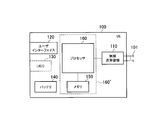
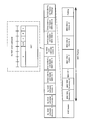
- FIG. 2 is a block diagram of the UE 100.
- the UE 100 includes an antenna 101, a wireless transceiver 110, a user interface 120, a UICC (Universal Integrated Circuit Card) 130, a battery 140, a memory 150, and a processor 160.
- the memory 150 corresponds to a storage unit
- the processor 160 corresponds to a control unit (controller).
- the memory 150 may be integrated with the processor 160, and this set (that is, a chip set) may be used as a processor 160 '(controller) that constitutes a control unit.
- the controller executes various processes and various communication protocols described later.
- the antenna 101 and the wireless transceiver 110 are used for transmitting and receiving wireless signals.
- the radio transceiver 110 converts the baseband signal (transmission signal) output from the processor 160 into a radio signal and transmits it from the antenna 101. Further, the radio transceiver 110 converts a radio signal received by the antenna 101 into a baseband signal (received signal) and outputs the baseband signal to the processor 160.
- the wireless transceiver 110 and the processor 160 constitute a transmission unit and a reception unit.
- the wireless transceiver 110 may include a plurality of transmitters and / or a plurality of receivers. The embodiment mainly assumes a case where the wireless transceiver 110 includes only one transmitter and one receiver.
- the user interface 120 is an interface with a user who owns the UE 100, and includes, for example, a display, a microphone, a speaker, and various buttons.
- the user interface 120 receives an operation from the user and outputs a signal indicating the content of the operation to the processor 160.
- the UICC 130 is a detachable storage medium that stores subscriber information.
- the UICC 130 may be referred to as a SIM (Subscriber Identity Module) or a USIM (Universal SIM).
- SIM Subscriber Identity Module
- USIM Universal SIM
- the UICC 130 stores a “Pre-configured parameter” to be described later.
- the battery 140 stores power to be supplied to each block of the UE 100.
- the UE 100 is a card type terminal, the UE 100 may not include the user interface 120 and the battery 140.
- the memory 150 stores a program executed by the processor 160 and information used for processing by the processor 160.
- the processor 160 includes a baseband processor that modulates / demodulates and encodes / decodes a baseband signal, and a CPU (Central Processing Unit) that executes programs stored in the memory 150 and performs various processes. .
- the processor 160 may further include a codec that performs encoding / decoding of an audio / video signal.
- the processor 160 executes various processes and various communication protocols described later.
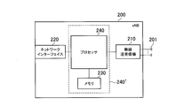
- FIG. 3 is a block diagram of the eNB 200.
- the eNB 200 includes an antenna 201, a radio transceiver 210, a network interface 220, a memory 230, and a processor 240 (controller).
- the memory 230 may be integrated with the processor 240, and this set (that is, a chip set) may be used as a processor 240 '(controller) that constitutes a control unit.
- the antenna 201 and the wireless transceiver 210 are used for transmitting and receiving wireless signals.
- the radio transceiver 210 converts the baseband signal (transmission signal) output from the processor 240 into a radio signal and transmits it from the antenna 201.
- the radio transceiver 210 converts a radio signal received by the antenna 201 into a baseband signal (received signal) and outputs the baseband signal to the processor 240.
- the wireless transceiver 210 and the processor 240 constitute a transmission unit and a reception unit.
- the network interface 220 is connected to the neighboring eNB 200 via the X2 interface and is connected to the MME / S-GW 300 via the S1 interface.
- the network interface 220 is used for communication performed on the X2 interface and communication performed on the S1 interface.
- the memory 230 stores a program executed by the processor 240 and information used for processing by the processor 240.
- the processor 240 includes a baseband processor that performs modulation / demodulation and encoding / decoding of a baseband signal, and a CPU that executes programs stored in the memory 230 and performs various processes.
- the processor 240 executes various processes and various communication protocols described later.
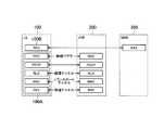
- FIG. 4 is a protocol stack diagram of a radio interface in the LTE system. As shown in FIG. 4, the radio interface protocol is divided into the first to third layers of the OSI reference model, and the first layer is a physical (PHY) layer.
- the second layer includes a MAC (Medium Access Control) layer, an RLC (Radio Link Control) layer, and a PDCP (Packet Data Convergence Protocol) layer.
- the third layer includes an RRC (Radio Resource Control) layer.
- the physical layer performs encoding / decoding, modulation / demodulation, antenna mapping / demapping, and resource mapping / demapping. Between the physical layer of UE100 and the physical layer of eNB200, user data and a control signal are transmitted via a physical channel.
- the MAC layer performs data priority control, retransmission processing by hybrid ARQ (HARQ), and the like. Between the MAC layer of the UE 100 and the MAC layer of the eNB 200, user data and control signals are transmitted via a transport channel.
- the MAC layer of the eNB 200 includes a scheduler that determines (schedules) uplink / downlink transport formats (transport block size, modulation / coding scheme) and resource blocks allocated to the UE 100.
- the RLC layer transmits data to the RLC layer on the receiving side using the functions of the MAC layer and the physical layer. Between the RLC layer of the UE 100 and the RLC layer of the eNB 200, user data and control signals are transmitted via a logical channel.
- the PDCP layer performs header compression / decompression and encryption / decryption.
- the RRC layer is defined only in the control plane that handles control signals. Control signals (RRC messages) for various settings are transmitted between the RRC layer of the UE 100 and the RRC layer of the eNB 200.
- the RRC layer controls the logical channel, the transport channel, and the physical channel according to establishment, re-establishment, and release of the radio bearer.
- RRC connection When there is a connection (RRC connection) between the RRC of the UE 100 and the RRC of the eNB 200, the UE 100 is in the RRC connected mode, otherwise, the UE 100 is in the RRC idle mode.
- the NAS (Non-Access Stratum) layer located above the RRC layer performs session management and mobility management.
- the physical layer or the RRC layer constitutes an AS (Access Stratum) entity 100A.
- the NAS layer constitutes the NAS entity 100B.
- the functions of the AS entity 100A and the NAS entity 100B are executed by the processor 160 (control unit). That is, the processor 160 (control unit) includes the AS entity 100A and the NAS entity 100B.
- the AS entity 100A performs cell selection / reselection, and the NAS entity 100B performs PLMN selection.
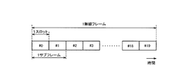
- FIG. 5 is a configuration diagram of a radio frame used in the LTE system.
- OFDMA Orthogonal Frequency Division Multiple Access
- SC-FDMA Single Carrier Frequency Multiple Access
- the radio frame is composed of 10 subframes arranged in the time direction.
- Each subframe is composed of two slots arranged in the time direction.
- the length of each subframe is 1 ms, and the length of each slot is 0.5 ms.
- Each subframe includes a plurality of resource blocks (RB) in the frequency direction and includes a plurality of symbols in the time direction.
- Each resource block includes a plurality of subcarriers in the frequency direction.
- a resource element is composed of one subcarrier and one symbol.
- frequency resources are configured by resource blocks
- time resources are configured by subframes (or slots).
- the LTE system according to the first embodiment supports D2D proximity service.
- the D2D proximity service is a service that enables direct UE-to-UE communication within a synchronized cluster composed of a plurality of synchronized UEs 100.
- the D2D proximity service includes a D2D discovery procedure (ProSe Discovery) for discovering a neighboring UE and D2D communication (ProSe Communication) that is direct UE-to-UE communication.
- the D2D communication may be referred to as “Direct communication”.
- a scenario in which all the UEs 100 forming the synchronous cluster are located in the cell coverage is referred to as “in coverage”.
- a scenario in which all UEs 100 forming a synchronous cluster are located outside cell coverage is referred to as “out of coverage”.
- a scenario in which some UEs 100 in the synchronization cluster are located within the cell coverage and the remaining UEs 100 are located outside the cell coverage is referred to as “partial coverage”.
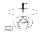
- FIG. 6 is a diagram illustrating an operating environment according to the first embodiment.
- FIG. 6 shows a state where the UE 100-1, UE 100-2, and UE 100-3 are using the D2D proximity service outside the coverage of the eNB 200.
- three UEs 100 are shown, but at least two UEs may be used.
- UE 100-1 is the synchronization source and UE 100-2 and UE 100-3 are the asynchronous sources.
- the UE 100-1, UE 100-2, and UE 100-3 are synchronized with each other using the UE 100-1 as a synchronization source.
- the UE 100-1, the UE 100-2, and the UE 100-3 execute the D2D discovery procedure while being synchronized with each other.
- each UE 100 (UE 100-1, UE 100-2, UE 100-3) transmits a D2D discovery signal (Discovery signal) for discovering neighboring terminals.
- a D2D discovery signal (Discovery signal) for discovering neighboring terminals.
- a first method in which radio resources not uniquely allocated to the UE 100 are used for transmission of the D2D discovery signal, and radio resources uniquely allocated to each UE 100 are D2D discovery signals.
- a second method (Type 2 discovery) used for transmission.
- a resource pool for D2D discovery signals is used for transmission of D2D discovery signals.
- the resource pool for the D2D discovery signal is shared in a synchronization cluster including a plurality of synchronized UEs 100.
- Mode 1 two operation modes (Mode1 / Mode2) are defined for D2D communication.
- the eNB 200 or a relay node (not shown) allocates radio resources for transmitting D2D data (D2D data and / or control data).
- the UE 100 itself selects a radio resource for transmitting D2D data (D2D data and / or control data) from the resource pool.
- D2D discovery procedure is executed using the operation of Mode 2 of D2D communication. That is, in the first embodiment, a scenario is assumed in which UE 100-1 performs D2D communication by Mode-2 in “out of coverage” and transmits a D2D discovery signal in a resource pool for D2D communication.
- This scenario may be referred to as “Discovery through Communication (DtC) for out of coverage”.
- DTC scenario outside coverage it will be referred to as “DTC scenario outside coverage” as appropriate.
- the configuration of the resource pool for D2D communication shown above is pre-configured.
- the preset parameters are hereinafter referred to as “Pre-configured parameters”.
- the information element included in the Pre-configured parameter is set to the same pre-configured parameter for UEs used for the same purpose (military, fire fighting, police, etc.).
- the resource pool for D2D communication is composed of a control information resource pool and a data resource pool.
- Information indicating the configuration of each resource pool includes a parameter (offset value for specifying a start position) for specifying a time / frequency region in which a resource pool for D2D communication is first configured in a radio frame, and a resource pool for D2D communication
- a parameter offset value for specifying a start position
- a resource pool for D2D communication For specifying a frequency direction resource (frequency direction resource specifying parameter), a repetition period (period) of the resource pool for D2D communication, and a time / frequency resource in which a specific subframe can be used for D2D communication Information (bitmap information) indicating whether or not.
- the Pre-configured parameter is provided to the UE 100.
- the Pre-configured parameter is stored in advance in the UICC 130 of the UE 100. If the Pre-configured parameter is not stored in the UICC 130 in advance, the UE 100 may be stored in the memory 150 by receiving provision from the network (OAM or the like) via the eNB at a predetermined opportunity.
- each UE 100 can transmit communication data using time / frequency resources in the resource pool for D2D communication.
- the UE 100 on the transmission side executes the D2D discovery procedure, it is necessary to transmit the D2D discovery signal using the time / frequency resource in the resource pool for D2D communication. Then, it is assumed that UE 100 on the receiving side cannot distinguish whether the received signal is a D2D discovery signal or a communication data signal.
- FIG. 7 shows an operation state according to the first embodiment.
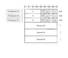
- FIG. 8 shows a usage example of the MAC header according to the first embodiment.
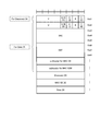
- FIG. 9 shows the structure of the MAC header and the MAC payload.
- FIG. 10 shows another usage example (1) of the MAC header.
- FIG. 11 shows another usage example (2) of the MAC header.
- FIG. 12 shows another usage example (3) of the MAC header.
- FIG. 13 shows another configuration of the MAC header and the MAC payload.
- FIG. 14 shows still another configuration of the MAC header and the MAC payload.
- the controller 160 160 '
- the UE 100-1 is a synchronization source
- the other UEs 100 are asynchronous sources.
- a plurality of UEs 100 are synchronized with each other using the UE 100-1 as a synchronization source.
- each UE 100 of the plurality of UEs 100 stores a pre-configured parameter including information indicating a configuration of a resource pool for D2D communication in the UICC 130 in advance.
- the UE 100 determines to transmit a D2D discovery signal (Discovery signal) in the D2D communication resource pool when the D2D communication can be executed in Mode 2 outside the coverage (step S101).
- Discovery signal D2D discovery signal
- a MAC entity (not shown) of the UE 100 generates information in the MAC layer.
- the MAC entity generates a MAC header that constitutes control information for Discovery (for D2D discovery procedure) and a MAC payload for Discovery (step S102).
- the “v” field of octed 1 indicates the version of the communication system.
- the “v” field may indicate information other than the version of the communication system.
- the “C / D” field following the “v” field is 1 indicating whether data (MAC payload in the first embodiment) carried by the D2D data resource is used for Communication or Discovery. This is identification information consisting of bits (“0” or “1”).
- the “C / D” field in FIG. 8 indicates “1”. In this case, “1” indicates that the MAC payload stored in the subsequent field is used for Discovery. If the “C / D” field is “0”, it indicates that the MAC payload stored in the subsequent field is used for communication.
- An “X” field following the “C / D” field is an “SRC” field (identification of the source UE) indicating the identification information of the own user terminal 100 (source UE ID) for communication data transmission to a specific user terminal 100.
- 1 bit indicating whether or not the “DST” field (FIG. 10) indicating the identification information of the specific user terminal 100 (the ID of the target UE) (FIG. 10) is stored in the subsequent field.
- the “X” fields in FIG. 8 all indicate “0”. “0” in this case indicates that the “SRC” field and the “DST” field are not configured in the subsequent fields.
- an “SRC” field and a “DST” field are configured in the subsequent fields.
- the “Y” field is extension information indicating whether or not the MAC payload stored in the subsequent field is the last payload as a payload used for Discovery or Communication.
- the “Y” field of octed 1 and octed 2 in FIG. 8 indicates “1”. In this case, “1” means that the MAC payload stored in the subsequent field is not the last payload as the payload used for Discovery, but the MAC payload stored in the subsequent field is still used for another Discovery.
- Indicates that The “Y” field of octet 3 in FIG. 8 indicates “0”. In this case, “0” indicates that the MAC payload stored in the subsequent field is the last payload as a payload used for Discovery.
- FIG. 8 shows the configuration of a MAC PDU in which three Discovery MAC payloads (Discovery ⁇ A ⁇ , ⁇ B ⁇ , ⁇ C ⁇ ) are stored.
- the example of FIG. 10 illustrates a configuration in which one Discovery MAC payload (Discovery ⁇ A ⁇ ) and Data for a specific user terminal 100 (Data ⁇ A ⁇ ) are stored in one MAC PDU.
- step S102 when the MAC entity of the UE 100 generates a MAC header and a MAC payload as shown in FIG. 8 in step S102, the generated information is sent to the PHY layer of the UE 100 (step S103).
- the PHY layer of the UE 100 executes a process of transmitting the information from the MAC layer using a time / frequency resource (radio resource) for D2D communication in a resource pool for D2D communication set in advance (step S104). ).
- Receiving UE 100 that has received the data transmitted in step S104, in the MAC layer, the bits indicated in the “C / D” field, “X” field, and “Y” field shown in FIG. 8 (FIG. 10). Recognize information. The receiving-side UE 100 executes the subsequent process after understanding the meaning of the information indicated by each field described above.
- FIG. 10 is applied when the D2D discovery procedure and the D2D communication are executed simultaneously.
- “MAC header for MAC CE” and “subheader for MAC SDU”, which are also used in cellular communication, are shown in the field after the sub header for octets 2 to 8 (SL-SCH sub header). Configure.
- the number of octets in the “DST” field in this case is the case of a normal D2D communication scenario (D2D data). It may be set to be larger than the number of octets in the “DST” field configured when the D2D discovery procedure using resources is not executed).
- the number of octets in the “DST” field configured in the case of the normal D2D communication scenario is “2” (16 bits)
- the number of octets in the “DST” field is “3”. (24 bits).
- the number of octets in the “DST” field may be “3” or more.
- the reason for extending the “DST” field is as follows.
- the UE 100 on the transmission side can send identification information (target UE-ID) of the target UE 100 using an SC (Sidelink Control) resource pool.
- SC Systemlink Control
- transmission of the identification information of the target UE using the SC resource pool is omitted.
- the transmitting UE 100 can transmit the D2D discovery signal without specifying the target UE.
- an opportunity to allow the specific UE 100 to acquire the identification information of the target UE is secured by increasing the number of octets in the “DST” field.
- the UE 100 other than the specific UE 100 recognizes that the target UE-ID stored in the “DST” field is not the ID for the own UE, it can discard the subsequent MAC payload. Further, if the specific UE 100 can recognize that the target UE-ID stored in the “DST” field is an ID for the own UE, the specific UE 100 can perform a subsequent MAC payload reception operation.
- FIG. 11 shows the field contents when the UE 100 having the capability of transmitting the Discovery MAC payload described above transmits Communication data in a predetermined period. The contents of each field are as described above.
- SCI sidelink control information
- the ID (destination ID) of the target UE in the “DST” field in the MAC header Store without omitting.
- the MAC entity of the UE 100 further displays the MAC EDU of Oct11 indicating the presence or absence of the MAC subheader for MAC SDU or MAC CE designation.
- the MAC entity of the UE 100 recognizes that the MAC SDU or MAC CE is stored from the next octet.
- Discovery (A) corresponding to the MAC subheader for discovery stored at the beginning of the MAC header is stored.
- the transmission source UE 100 stores MAC control information (MAC Control Element (MAC CE)) directed to a plurality of destination UEs 100 in the MAC PDU.
- MAC CE MAC Control Element
- the transmission source UE 100 does not designate a specific UE 100 and wants to notify the MAC CE
- the MAC UE for MAC CE is stored after the MAC subheader for Discovery.
- the transmission source UE 100 wishes to notify a specific user of the MAC CE
- the transmission source UE 100 stores the MAC CE after the MAC subheader for the communication data of the specific destination UE 100.
- the receiving side (transmission destination) UE 100 receives two MAC CEs at the same time, the receiving side UE 100 may use one of the MAC CEs, or the MAC CE notified to a specific destination UE 100. May be used with priority.
- the MAC subheader that specifies data for communication includes SRC that is an identifier indicating the source UE 100. Therefore, when the transmission source UE 100 multiplexes communication data for a plurality of destination UEs 100 in the MAC PDU, the transmission source UE 100 notifies the SRC with a MAC subheader that specifies the communication data of a certain destination UE 100, and other than that In the MAC subheader designating communication data of another destination, the number of octets used for the MAC subheader may be reduced by omitting SRC.
- the “C / D” field is configured in the MAC header, and the MAC payload stored in the subsequent field is the payload used for Discovery for the “C / D” field.
- the MAC payload stored in the subsequent field is indirectly used for Discovery by the version information indicated by the “v” field. May be used as a payload.
- the version information indicated in the “v” field indicates the latest version, an agreement is defined in advance that the MAC payload stored in the subsequent field indicates that the payload is used for Discovery. Just keep it.
- the UE 100 stores identification information indicating that the MAC payload stored in the later field is a payload used for Discovery, in the MAC header.
- the UE 100 generates data for the discovery using the MAC payload in the field after the identification information, and transmits the generated data using the D2D data resource in the preset resource pool for D2D communication. be able to.
- the UE 100 on the receiving side can understand from the identification information that the received MAC payload is used for Discovery. For this reason, in the DTC scenario outside the coverage, the D2D discovery procedure is efficiently performed between a plurality of user terminals.
- FIG. 15 is a diagram for explaining the Communication resource pool according to the second embodiment.
- FIG. 16 is a diagram illustrating an operation state according to the second embodiment.
- FIG. 17 is a diagram illustrating the contents of the first SC according to the second embodiment.
- FIG. 18 shows the contents of the second SC according to the second embodiment.
- the UE 100 stores identification information indicating that the MAC payload stored in the subsequent field is a payload used for Discovery in the MAC header has been described.
- the SC (Sidelink Control) resource pool of the communication resource pool set in advance the data carried in the data pool (D2D data resource) is used for the D2D discovery procedure.
- the resource pool means a time / frequency resource group composed of a predetermined amount (number) of time / frequency resources.
- the Communication resource pool includes an SC resource pool (SCP Pool) that is a pool of radio resources that can be used for transmission / reception of sidelink control information (Sidelink Control Information: SCI), and a pool of radio resources that can be used for transmission / reception of D2D communication data.
- SC resource pool SCP Pool
- Data resource pool DataPool
- UE 100 selects radio resources used for data transmission from time / frequency resources in a data resource pool (data region: Data Region) periodically arranged in the time direction. For example, when the UE 100 randomly sets the timing for transmitting the same data in the time direction, the UE 100 randomly selects four subframes from the time and frequency resources in the first half of the data area, and the second half of the data area. Four subframes are randomly selected from the time and frequency resources. The UE 100 transmits data using the selected eight subframes. Alternatively, the UE 100 repeatedly transmits data using the four subframes selected from the time and frequency resources in the first half of the data region, and the four subframes selected from the time and frequency resources in the first half of the data region. Another data may be repeatedly transmitted using a frame.
- data region Data Region
- “Y” means the frequency direction
- “t” means the time direction.
- (A) is an offset (SC start position offset) indicating a position where the SC resource pool is started in the radio frame. The range of the SC start position offset is 0 to 10239 subframes.
- (B) shows the repetition cycle of the Communication resource pool in the radio frame. As the repetition period, “40 subframes”, “80 subframes”, “160 subframes”, or “320 subframes” are applied.
- (C) is an offset (Data start position offset) indicating a position where the data resource pool is started in the radio frame. The range of Data start position offset is 0-10239 subframes.
- the UE 100 receives information (Scheduling Assignment: SA) indicating the position of the time / frequency resource for data transmitted by D2D communication from the time / frequency resources in the SC resource pool periodically arranged in the time direction. Select time and frequency resources for transmission.
- SA Service Assignment
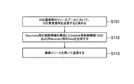
- step S101 the UE 100 generates sidelink control information (SCI) that constitutes control information for discovery (for D2D discovery procedure) and data for discovery (step S112).
- SCI sidelink control information
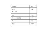
- the SCI (first SCI) includes a UEID (UE identifier) and an MCS.
- the UEID is the SA transmission destination ID (Target ID).
- the UEID is an 8-bit bit string.
- the first 1 bit of the UEID may be information indicating whether to transmit user data by broadcast. Thereby, UE100 which received SA can erase
- MCS indicates MCS (Modulation and Coding Scheme) of transmission data.
- MCS is a 5-bit bit string.
- the Discovery identification information indicates that data carried in the data pool of the Communication resource pool is used for the D2D discovery procedure.
- the Discovery identification information is 1-bit information.
- the Discovery identification information may be represented by “1” when indicating that data carried in the data pool of the Communication resource pool is used for the D2D discovery procedure, and by “0” otherwise.
- the UE 100 determines time / frequency resources (radio resources) in the SC resource pool in order to wirelessly transmit the SCI generated in step S112. Further, the UE 100 determines time / frequency resources (radio resources) in the data resource pool in order to wirelessly transmit the discovery data generated in step S112. Thereafter, the UE 100 transmits data for SCI and Discovery using the determined radio resource (step S113).
- the receiving-side UE 100 that has received the SCI and Discovery data transmitted in step S113 recognizes the Discovery identification information indicated in the SCI.
- the receiving side UE 100 understands the meaning indicated by the Discovery identification information and executes subsequent processing.
- the example which comprises Discovery identification information in SCI was shown.
- the Discovery identification information in this case is explicit information.
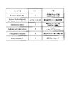
- the SCI (second SCI) does not constitute Discovery identification information.
- the UEID in SCI (“Group destination ID” in FIG. 18) is defined as a UEID dedicated to Discovery transmission.
- the UEID dedicated to Discovery transmission indicates that the time / frequency resource for data indicated by the SCI is used for Discovery.
- the UEID dedicated to Discovery transmission in this case can be positioned as explicit information. Note that the first SCI described above and the second SCI shown in the description of this example may be appropriately used.
- the “Modulation and coding scheme” field shown in FIG. 18 stores information indicating a specific MCS dedicated to Discovery suitable for Discovery transmission (an MCS that can ensure a relatively low rate among a plurality of MCSs).
- the specific MCS in this case is set to be distinguished from the MCS for data transmission.
- the specific MCS implicitly indicates that the time / frequency resource for data is used for Discovery.
- the transmission side UE 100 may transmit data for Discovery using time / frequency resources in a specific Communication resource pool.
- the receiving-side UE 100 can recognize the data received by the predetermined time / frequency resource in the specific Communication resource pool as the data for Discovery.
- the Pre-configured parameter indicating the presence or absence of the above-described rule can be regarded as implicit information.
- the UE 100 transmits to the SCI indicating that the time / frequency resource for data is used for the discovery, either explicitly or implicitly. .
- the UE 100 on the receiving side can understand that the time / frequency resource for data indicated by the received SCI is used for Discovery. For this reason, in the DTC scenario outside the coverage, the D2D discovery procedure is efficiently performed between a plurality of user terminals.
- the contents of the first embodiment and the second embodiment described above are implemented in a scenario of “out of coverage”, but may be implemented in a scenario of “partial coverage”.
- the LTE system has been described as an example of the mobile communication system.
- the present invention is not limited to the LTE system, and the present invention may be applied to a system other than the LTE system.
- the present invention is useful in the communication field.
Abstract
Description
第1実施形態に係るユーザ端末は、直接的な端末間通信であるD2D(Device to Device)通信をサポートする移動通信システムにおいて用いられる。ユーザ端末は、コントローラを備える。前記コントローラは、セルカバレッジ外のユーザ端末を対象としたD2D発見手続きを実行すると決めた場合には、事前に設定されたD2D通信用のリソースプールにおけるD2Dデータリソースを用いてD2D発見手続を実行する。前記コントローラは、前記D2D発見手続を実行するときには、前記D2Dデータリソースによって運ばれるデータが当該D2D発見手続のために使用されることを示す識別情報を送信する処理を実行する。
以下において、本発明をLTEシステムに適用する場合の実施形態を説明する。
図1は、第1実施形態に係るLTEシステムの構成図である。図1に示すように、第1実施形態に係るLTEシステムは、UE(User Equipment)100、E-UTRAN(Evolved Universal Terrestrial Radio Access Network)10、及びEPC(Evolved Packet Core)20を備える。
以下において、第1実施形態に係るD2D近傍サービスについて、D2D発見手続を主として説明する。第1実施形態に係るLTEシステムは、D2D近傍サービスをサポートする。
上述したように、カバレッジ外にいる同期クラスタを構成する複数のUE100は、Mode2でD2D通信を実行し得る。この場合、各UE100は、D2D通信用のリソースプールにおける時間・周波数リソースを使って、Communicationデータを送信できる。ここで、送信側のUE100が、D2D発見手続を実行する場合、D2D通信用のリソースプールにおける時間・周波数リソースを使って、D2D発見信号を送信しなければならない。そうすると、受信側のUE100は、受信した信号がD2D発見信号なのかCommunicationデータ用の信号なのかの区別がつかない事態が想定される。
以下、図7乃至図14に基づいて、第1実施形態の動作内容について説明する。図7は、第1実施形態に係る動作状態を示す。図8は、第1実施形態に係るMACヘッダの使用例を示す。図9は、MACヘッダとMACペイロードの構成を示す。図10は、MACヘッダのその他の使用例(1)を示す。図11は、MACヘッダのその他の使用例(2)を示す。図12は、MACヘッダのその他の使用例(3)を示す。図13は、MACヘッダとMACペイロードの別の構成を示す。図14は、MACヘッダとMACペイロードの更に別の構成を示す。尚、UE100が実行する処理については、該UE100のコントローラ160(160’)が処理を実行するが、図7乃至14の説明においては、便宜上、UE100が行うものとして説明する。
図11及び図12は、MACヘッダのその他の使用例を示す。図11の例は、上述したDiscovery用のMACペイロードを送信できる能力を有したUE100が、所定の期間においてCommunicationデータを送信する場合のフィールドの内容を示す。各フィールドの内容は上述した通りである。尚、図11の例では、後述するSidelink用制御情報(Sidelink Control Information:SCI)においてブロードキャスト用のIDが使用されているため、MACヘッダ内の「DST」フィールドにターゲットUEのID(送り先ID)を省略せずに格納する。
上述した第1実施形態では、MACヘッダに「C/D」フィールドを構成し、該「C/D」フィールドに、後のフィールドに格納されるMACペイロードがDiscovery用として使用されるペイロードであることを示す識別情報を格納したが、このような「C/D」フィールドを構成せずに、「v」フィールドで示されるバージョン情報によって間接的に、後のフィールドに格納されるMACペイロードがDiscovery用として使用されるペイロードであることを示してもよい。つまり、「v」フィールドで示されるバージョン情報が最新のバージョンを示す場合には、後のフィールドに格納されるMACペイロードがDiscovery用として使用されるペイロードであることを示す、という取り決めを予め定義しておけばよい。
第1実施形態では、上述したように、UE100は、MACヘッダに、後のフィールドに格納されるMACペイロードがDiscovery用として使用されるペイロードであることを示す識別情報を格納する。加えて、UE100は、該識別情報の後のフィールドのMACペイロードをDiscovery用としたデータを生成し、生成したデータを事前に設定されたD2D通信用のリソースプールにおけるD2Dデータリソースを用いて送信することができる。受信側のUE100は、前記識別情報によって、受信したMACペイロードがDiscovery用として使われていることを理解できる。このため、カバレッジ外でのDTCシナリオにおいて、複数のユーザ端末間で効率良くD2D発見手続が行われる。
次に、図15乃至図18を用いて第2実施形態について説明する。第1実施形態と同様の部分は、説明を適宜省略する。図15は、第2実施形態に係るCommunicationリソースプールを説明するための図である。図16は、第2実施形態に係る動作状態を示す図である。図17は、第2実施形態に係る第1のSCの内容を示す図である。図18は、第2実施形態に係る第2のSCの内容を示す。
上述した第2実施形態では、SCIにおいてDiscovery識別情報を構成する例を示した。この場合のDiscovery識別情報は明示的な情報である。これに対して、第2実施形態の変形例1では、図18に示すように、SCI(第2のSCI)は、Discovery識別情報を構成しない。第2実施形態の変形例1では、SCIにおけるUEID(図18の「Group destination ID」)を、Discovery送信専用のUEIDとして定義する。この場合、Discovery送信専用のUEIDは、当該SCIが示すデータ用の時間・周波数リソースがDiscovery用に使用されることを示す。この場合のDiscovery送信専用のUEIDは、明示的な情報と位置付け得る。尚、上述した第1のSCIと本例の説明で示された第2のSCIを適宜使い分けてもよい。
また、上述した第2実施形態及び第2実施形態の変形例1以外の例もある。例えば、図18に示した「Modulation and coding scheme」フィールドにおいて、Discovery送信に適したDiscovery専用の特定MCS(複数のMCSのうち、相対的に低いレートを確保できるMCS)を示す情報を格納する。この場合の特定MCSは、データ送信用のMCSと区別されるように設定される。尚、特定MCSは、暗黙的に、データ用の時間・周波数リソースがDiscovery用に使用されることを示す。
また、上述した例の他に、D2D近傍サービスのDTCシナリオにおいて、特定のCommunicationリソースプールでD2D発見信号の伝送が許可される、というルールが事前設定(Pre-configured)されるならば、送信側のUE100は、特定のCommunicationリソースプールにおける時間・周波数リソースを用いてDiscovery用のデータを送信してもよい。この場合、受信側のUE100は、特定のCommunicationリソースプールにおける所定の時間・周波数リソースで受信したデータをDiscovery用のデータとして認識できる。この場合、上述したルールの有無を示すPre-configuredパラメータが暗黙的な情報と位置付け得る。
第2実施形態及び変形例1及び2では、上述したように、UE100は、SCIに、明示的あるいは暗黙的に、データ用の時間・周波数リソースがDiscovery用に使用されることを示して送信した。この場合、受信側のUE100は、受信したSCIが示すデータ用の時間・周波数リソースがDiscovery用に使用されることを理解できる。このため、カバレッジ外でのDTCシナリオにおいて、複数のユーザ端末間で効率良くD2D発見手続が行われる。
上述した第1実施形態及び第2実施形態の内容は、それぞれ別に実施し得るが、第1実施形態はMACレイヤでの動作であり、第2実施形態は、MACレイヤよりも下位のレイヤでの動作であるため、両実施形態を組み合わせて実施してもよい。
日本国特許出願第2015-081202号(2015年4月10日)の全内容が参照により本願明細書に組み込まれている。
Claims (9)
- 直接的な端末間通信であるD2D(Device to Device)通信をサポートする移動通信システムにおいて用いられるユーザ端末であって、
コントローラを備え、
前記コントローラは、セルカバレッジ外のユーザ端末を対象にしたD2D発見手続を実行すると決めた場合には、事前に設定されたD2D通信用のリソースプールにおけるD2Dデータリソースを用いてD2D発見手続を実行し、
前記コントローラは、前記D2D発見手続を実行するときには、前記D2Dデータリソースによって運ばれるデータが当該D2D発見手続のために使用されることを示す識別情報を送信する処理を実行する、ユーザ端末。 - 前記データは、MAC(Medium Access Control)レイヤにおけるデータであり、前記識別情報は、MACサブヘッダにおける第1のフィールドにおいて構成される、前記請求項1記載のユーザ端末。
- 前記MACサブヘッダは、第2のフィールドにおいて、前記データが前記D2D発見手続のために使用される最後のデータであるか否かを示す第1の拡張情報を構成する、前記請求項2記載のユーザ端末。
- 前記MACサブヘッダは、特定のユーザ端末を対象としたD2Dデータ送信のために、自ユーザ端末の識別情報を示す第3のフィールド及び前記特定のユーザ端末の識別情報を示す第4のフィールドを構成可能であり、
前記MACサブヘッダは、更に、前記第3のフィールド及び前記第4のフィールドの存在の有無を示す第2の拡張情報を、第5のフィールドにおいて構成可能である、前記請求項3記載のユーザ端末。 - 前記MACサブヘッダは、前記第4のフィールドのオクテッド数を、前記D2Dデータリソースを用いたD2D発見手順が実行されない場合に構成される第6のフィールドのオクテッド数よりも多く設定し、
前記第6のフィールドは、データの送信先ユーザ端末の識別情報を構成する、前記請求項4記載のユーザ端末。 - 前記データは、MACレイヤよりも下位のレイヤにおいて運ばれるデータであり、前記識別情報は、前記D2D通信用のリソースプールにおける制御情報用の時間・周波数リソース領域において運ばれる情報である、前記請求項1記載のユーザ端末。
- 前記識別情報は、明示的な情報である前記請求項6記載のユーザ端末。
- 前記識別情報は、特定のMCS(Modulation and Coding Scheme)によって暗黙的に示される情報である前記請求項6記載のユーザ端末。
- 直接的な端末間通信であるD2D(Device to Device)通信をサポートする移動通信システムにおいて用いられるユーザ端末における制御方法であって、
セルカバレッジ外のユーザ端末を対象にしたD2D発見手続を実行する場合、事前に設定されたD2D通信用のリソースプールにおけるD2Dデータリソースを用いてD2D発見手続を実行し、
前記D2D発見手続を実行するときには、前記D2Dデータリソースによって運ばれるデータが当該D2D発見手続のために使用されることを示す識別情報を送信する制御方法。
Priority Applications (2)
| Application Number | Priority Date | Filing Date | Title |
|---|---|---|---|
| JP2017511065A JP6732185B2 (ja) | 2015-04-10 | 2016-04-07 | ユーザ端末及び制御方法 |
| US15/564,223 US10390207B2 (en) | 2015-04-10 | 2016-04-07 | User terminal and control method |
Applications Claiming Priority (2)
| Application Number | Priority Date | Filing Date | Title |
|---|---|---|---|
| JP2015081202 | 2015-04-10 | ||
| JP2015-081202 | 2015-04-10 |
Publications (1)
| Publication Number | Publication Date |
|---|---|
| WO2016163476A1 true WO2016163476A1 (ja) | 2016-10-13 |
Family
ID=57071823
Family Applications (1)
| Application Number | Title | Priority Date | Filing Date |
|---|---|---|---|
| PCT/JP2016/061436 WO2016163476A1 (ja) | 2015-04-10 | 2016-04-07 | ユーザ端末及び制御方法 |
Country Status (3)
| Country | Link |
|---|---|
| US (1) | US10390207B2 (ja) |
| JP (1) | JP6732185B2 (ja) |
| WO (1) | WO2016163476A1 (ja) |
Families Citing this family (2)
| Publication number | Priority date | Publication date | Assignee | Title |
|---|---|---|---|---|
| WO2017193350A1 (zh) * | 2016-05-12 | 2017-11-16 | 华为技术有限公司 | 信息传输的方法及用户设备 |
| KR20200127402A (ko) * | 2019-05-02 | 2020-11-11 | 삼성전자주식회사 | 단말 직접 통신시스템에서 패킷 송수신 영역 결정 방법 및 장치 |
Citations (2)
| Publication number | Priority date | Publication date | Assignee | Title |
|---|---|---|---|---|
| JP2015012590A (ja) * | 2013-07-02 | 2015-01-19 | 株式会社Nttドコモ | 基地局、ユーザ装置、リソース割り当て方法、及びリソース決定方法 |
| WO2015046264A1 (ja) * | 2013-09-27 | 2015-04-02 | 京セラ株式会社 | 通信制御方法及びユーザ端末 |
Family Cites Families (4)
| Publication number | Priority date | Publication date | Assignee | Title |
|---|---|---|---|---|
| US9980173B2 (en) * | 2014-02-10 | 2018-05-22 | Lg Electronics Inc. | Method and apparatus for indicating QoS of D2D data in wireless communication system |
| US10142847B2 (en) * | 2014-05-23 | 2018-11-27 | Qualcomm Incorporated | Secure relay of discovery information in wireless networks |
| WO2016048076A2 (ko) * | 2014-09-24 | 2016-03-31 | 엘지전자 주식회사 | D2d 신호의 송신 방법 및 이를 위한 단말 |
| EP4216654A1 (en) * | 2014-09-26 | 2023-07-26 | Sun Patent Trust | Improved resource allocation for device to device (d2d) communication |
-
2016
- 2016-04-07 WO PCT/JP2016/061436 patent/WO2016163476A1/ja active Application Filing
- 2016-04-07 US US15/564,223 patent/US10390207B2/en active Active
- 2016-04-07 JP JP2017511065A patent/JP6732185B2/ja active Active
Patent Citations (2)
| Publication number | Priority date | Publication date | Assignee | Title |
|---|---|---|---|---|
| JP2015012590A (ja) * | 2013-07-02 | 2015-01-19 | 株式会社Nttドコモ | 基地局、ユーザ装置、リソース割り当て方法、及びリソース決定方法 |
| WO2015046264A1 (ja) * | 2013-09-27 | 2015-04-02 | 京セラ株式会社 | 通信制御方法及びユーザ端末 |
Non-Patent Citations (4)
| Title |
|---|
| ALCATEL -LUCENT ET AL.: "L2 Addresses for Public Safety D2D discovery and communication user data", 3GPP TSG- RAN WG2#85 R2-140723, 1 February 2014 (2014-02-01), XP050737835, Retrieved from the Internet <URL:http://www.3gpp.org/ftp/tsg_ran/WG2_RL2/TSGR2_85/Docs/R2-140723.zip> * |
| HUAWEI ET AL.: "UE-to-Network Relay Discovery", 3GPP TSG-RAN WG1#80B R1- 151865, XP050934723, Retrieved from the Internet <URL:http://www.3gpp.org/ftp/tsg_ran/WG1_RL1/TSGR1_80b/Docs/R1-151865.zip> * |
| INTEL CORPORATION: "Discussion on ProSe out of coverage discovery[ online", 3GPP TSG-RAN WG2#85 R2-140730, 1 February 2014 (2014-02-01), XP050737841, Retrieved from the Internet <URL:http://www.3gpp.org/ftp/tsg_ran/WG2_RL2/TSGR2_85/Docs/R2-140730.zip> * |
| SONY: "Discussion on ProSe Discovery through Communication (DtC", 3 GPP TSG-RAN WG2#85 R2-140357, 31 January 2014 (2014-01-31), XP050737570, Retrieved from the Internet <URL:http://www.3gpp.org/ftp/tsg_ran/WG2_RL2/TSGR2_85/Docs/R2-140357.zip> * |
Also Published As
| Publication number | Publication date |
|---|---|
| JPWO2016163476A1 (ja) | 2018-02-08 |
| JP6732185B2 (ja) | 2020-07-29 |
| US10390207B2 (en) | 2019-08-20 |
| US20180132091A1 (en) | 2018-05-10 |
Similar Documents
| Publication | Publication Date | Title |
|---|---|---|
| US10911999B2 (en) | Mobile communication system, user terminal, base station, processor, and communication control method | |
| JP5826937B2 (ja) | 移動通信システム、基地局、ユーザ端末、及びプロセッサ | |
| JP6026549B2 (ja) | 移動通信システム、基地局及びユーザ端末 | |
| JP6532861B2 (ja) | 通信制御方法及び基地局 | |
| WO2016021700A1 (ja) | 通信制御方法及びユーザ端末 | |
| WO2015141727A1 (ja) | 通信制御方法及びユーザ端末 | |
| WO2016136493A1 (ja) | 基地局及び無線端末 | |
| JP6732185B2 (ja) | ユーザ端末及び制御方法 | |
| WO2015170765A1 (ja) | ユーザ端末及びプロセッサ | |
| WO2016163431A1 (ja) | ユーザ端末及び制御方法 | |
| WO2016136492A1 (ja) | 無線端末及び基地局 | |
| JP6515083B2 (ja) | ユーザ端末及び通信制御方法 | |
| JP6130592B2 (ja) | ユーザ端末及び装置 | |
| WO2016163474A1 (ja) | ユーザ端末 | |
| JP2018139430A (ja) | 移動通信システム、ユーザ端末、基地局、及びプロセッサ |
Legal Events
| Date | Code | Title | Description |
|---|---|---|---|
| 121 | Ep: the epo has been informed by wipo that ep was designated in this application |
Ref document number: 16776642 Country of ref document: EP Kind code of ref document: A1 |
|
| ENP | Entry into the national phase |
Ref document number: 2017511065 Country of ref document: JP Kind code of ref document: A |
|
| WWE | Wipo information: entry into national phase |
Ref document number: 15564223 Country of ref document: US |
|
| NENP | Non-entry into the national phase |
Ref country code: DE |
|
| 122 | Ep: pct application non-entry in european phase |
Ref document number: 16776642 Country of ref document: EP Kind code of ref document: A1 |