WO2016163377A1 - 接合体の製造方法 - Google Patents
接合体の製造方法 Download PDFInfo
- Publication number
- WO2016163377A1 WO2016163377A1 PCT/JP2016/061195 JP2016061195W WO2016163377A1 WO 2016163377 A1 WO2016163377 A1 WO 2016163377A1 JP 2016061195 W JP2016061195 W JP 2016061195W WO 2016163377 A1 WO2016163377 A1 WO 2016163377A1
- Authority
- WO
- WIPO (PCT)
- Prior art keywords
- temperature
- adherend
- glass frit
- crystallized glass
- joined body
- Prior art date
- Legal status (The legal status is an assumption and is not a legal conclusion. Google has not performed a legal analysis and makes no representation as to the accuracy of the status listed.)
- Ceased
Links
Images


Classifications
-
- C—CHEMISTRY; METALLURGY
- C03—GLASS; MINERAL OR SLAG WOOL
- C03C—CHEMICAL COMPOSITION OF GLASSES, GLAZES OR VITREOUS ENAMELS; SURFACE TREATMENT OF GLASS; SURFACE TREATMENT OF FIBRES OR FILAMENTS MADE FROM GLASS, MINERALS OR SLAGS; JOINING GLASS TO GLASS OR OTHER MATERIALS
- C03C4/00—Compositions for glass with special properties
- C03C4/14—Compositions for glass with special properties for electro-conductive glass
-
- C—CHEMISTRY; METALLURGY
- C03—GLASS; MINERAL OR SLAG WOOL
- C03C—CHEMICAL COMPOSITION OF GLASSES, GLAZES OR VITREOUS ENAMELS; SURFACE TREATMENT OF GLASS; SURFACE TREATMENT OF FIBRES OR FILAMENTS MADE FROM GLASS, MINERALS OR SLAGS; JOINING GLASS TO GLASS OR OTHER MATERIALS
- C03C10/00—Devitrified glass ceramics, i.e. glass ceramics having a crystalline phase dispersed in a glassy phase and constituting at least 50% by weight of the total composition
-
- C—CHEMISTRY; METALLURGY
- C03—GLASS; MINERAL OR SLAG WOOL
- C03C—CHEMICAL COMPOSITION OF GLASSES, GLAZES OR VITREOUS ENAMELS; SURFACE TREATMENT OF GLASS; SURFACE TREATMENT OF FIBRES OR FILAMENTS MADE FROM GLASS, MINERALS OR SLAGS; JOINING GLASS TO GLASS OR OTHER MATERIALS
- C03C27/00—Joining pieces of glass to pieces of other inorganic material; Joining glass to glass other than by fusing
- C03C27/04—Joining glass to metal by means of an interlayer
- C03C27/042—Joining glass to metal by means of an interlayer consisting of a combination of materials selected from glass, glass-ceramic or ceramic material with metals, metal oxides or metal salts
- C03C27/044—Joining glass to metal by means of an interlayer consisting of a combination of materials selected from glass, glass-ceramic or ceramic material with metals, metal oxides or metal salts of glass, glass-ceramic or ceramic material only
-
- C—CHEMISTRY; METALLURGY
- C03—GLASS; MINERAL OR SLAG WOOL
- C03C—CHEMICAL COMPOSITION OF GLASSES, GLAZES OR VITREOUS ENAMELS; SURFACE TREATMENT OF GLASS; SURFACE TREATMENT OF FIBRES OR FILAMENTS MADE FROM GLASS, MINERALS OR SLAGS; JOINING GLASS TO GLASS OR OTHER MATERIALS
- C03C3/00—Glass compositions
- C03C3/12—Silica-free oxide glass compositions
- C03C3/122—Silica-free oxide glass compositions containing oxides of As, Sb, Bi, Mo, W, V, Te as glass formers
-
- C—CHEMISTRY; METALLURGY
- C03—GLASS; MINERAL OR SLAG WOOL
- C03C—CHEMICAL COMPOSITION OF GLASSES, GLAZES OR VITREOUS ENAMELS; SURFACE TREATMENT OF GLASS; SURFACE TREATMENT OF FIBRES OR FILAMENTS MADE FROM GLASS, MINERALS OR SLAGS; JOINING GLASS TO GLASS OR OTHER MATERIALS
- C03C3/00—Glass compositions
- C03C3/12—Silica-free oxide glass compositions
- C03C3/14—Silica-free oxide glass compositions containing boron
-
- C—CHEMISTRY; METALLURGY
- C03—GLASS; MINERAL OR SLAG WOOL
- C03C—CHEMICAL COMPOSITION OF GLASSES, GLAZES OR VITREOUS ENAMELS; SURFACE TREATMENT OF GLASS; SURFACE TREATMENT OF FIBRES OR FILAMENTS MADE FROM GLASS, MINERALS OR SLAGS; JOINING GLASS TO GLASS OR OTHER MATERIALS
- C03C3/00—Glass compositions
- C03C3/12—Silica-free oxide glass compositions
- C03C3/16—Silica-free oxide glass compositions containing phosphorus
- C03C3/21—Silica-free oxide glass compositions containing phosphorus containing titanium, zirconium, vanadium, tungsten or molybdenum
-
- C—CHEMISTRY; METALLURGY
- C03—GLASS; MINERAL OR SLAG WOOL
- C03C—CHEMICAL COMPOSITION OF GLASSES, GLAZES OR VITREOUS ENAMELS; SURFACE TREATMENT OF GLASS; SURFACE TREATMENT OF FIBRES OR FILAMENTS MADE FROM GLASS, MINERALS OR SLAGS; JOINING GLASS TO GLASS OR OTHER MATERIALS
- C03C8/00—Enamels; Glazes; Fusion seal compositions being frit compositions having non-frit additions
- C03C8/02—Frit compositions, i.e. in a powdered or comminuted form
-
- C—CHEMISTRY; METALLURGY
- C03—GLASS; MINERAL OR SLAG WOOL
- C03C—CHEMICAL COMPOSITION OF GLASSES, GLAZES OR VITREOUS ENAMELS; SURFACE TREATMENT OF GLASS; SURFACE TREATMENT OF FIBRES OR FILAMENTS MADE FROM GLASS, MINERALS OR SLAGS; JOINING GLASS TO GLASS OR OTHER MATERIALS
- C03C8/00—Enamels; Glazes; Fusion seal compositions being frit compositions having non-frit additions
- C03C8/02—Frit compositions, i.e. in a powdered or comminuted form
- C03C8/08—Frit compositions, i.e. in a powdered or comminuted form containing phosphorus
-
- C—CHEMISTRY; METALLURGY
- C03—GLASS; MINERAL OR SLAG WOOL
- C03C—CHEMICAL COMPOSITION OF GLASSES, GLAZES OR VITREOUS ENAMELS; SURFACE TREATMENT OF GLASS; SURFACE TREATMENT OF FIBRES OR FILAMENTS MADE FROM GLASS, MINERALS OR SLAGS; JOINING GLASS TO GLASS OR OTHER MATERIALS
- C03C8/00—Enamels; Glazes; Fusion seal compositions being frit compositions having non-frit additions
- C03C8/14—Glass frit mixtures having non-frit additions, e.g. opacifiers, colorants, mill-additions
- C03C8/18—Glass frit mixtures having non-frit additions, e.g. opacifiers, colorants, mill-additions containing free metals
-
- C—CHEMISTRY; METALLURGY
- C03—GLASS; MINERAL OR SLAG WOOL
- C03C—CHEMICAL COMPOSITION OF GLASSES, GLAZES OR VITREOUS ENAMELS; SURFACE TREATMENT OF GLASS; SURFACE TREATMENT OF FIBRES OR FILAMENTS MADE FROM GLASS, MINERALS OR SLAGS; JOINING GLASS TO GLASS OR OTHER MATERIALS
- C03C8/00—Enamels; Glazes; Fusion seal compositions being frit compositions having non-frit additions
- C03C8/24—Fusion seal compositions being frit compositions having non-frit additions, i.e. for use as seals between dissimilar materials, e.g. glass and metal; Glass solders
-
- H—ELECTRICITY
- H10—SEMICONDUCTOR DEVICES; ELECTRIC SOLID-STATE DEVICES NOT OTHERWISE PROVIDED FOR
- H10W—GENERIC PACKAGES, INTERCONNECTIONS, CONNECTORS OR OTHER CONSTRUCTIONAL DETAILS OF DEVICES COVERED BY CLASS H10
- H10W40/00—Arrangements for thermal protection or thermal control
- H10W40/60—Securing means for detachable heating or cooling arrangements, e.g. clamps
-
- H—ELECTRICITY
- H10—SEMICONDUCTOR DEVICES; ELECTRIC SOLID-STATE DEVICES NOT OTHERWISE PROVIDED FOR
- H10W—GENERIC PACKAGES, INTERCONNECTIONS, CONNECTORS OR OTHER CONSTRUCTIONAL DETAILS OF DEVICES COVERED BY CLASS H10
- H10W72/00—Interconnections or connectors in packages
- H10W72/071—Connecting or disconnecting
-
- C—CHEMISTRY; METALLURGY
- C03—GLASS; MINERAL OR SLAG WOOL
- C03C—CHEMICAL COMPOSITION OF GLASSES, GLAZES OR VITREOUS ENAMELS; SURFACE TREATMENT OF GLASS; SURFACE TREATMENT OF FIBRES OR FILAMENTS MADE FROM GLASS, MINERALS OR SLAGS; JOINING GLASS TO GLASS OR OTHER MATERIALS
- C03C2204/00—Glasses, glazes or enamels with special properties
-
- C—CHEMISTRY; METALLURGY
- C03—GLASS; MINERAL OR SLAG WOOL
- C03C—CHEMICAL COMPOSITION OF GLASSES, GLAZES OR VITREOUS ENAMELS; SURFACE TREATMENT OF GLASS; SURFACE TREATMENT OF FIBRES OR FILAMENTS MADE FROM GLASS, MINERALS OR SLAGS; JOINING GLASS TO GLASS OR OTHER MATERIALS
- C03C2205/00—Compositions applicable for the manufacture of vitreous enamels or glazes
-
- H—ELECTRICITY
- H10—SEMICONDUCTOR DEVICES; ELECTRIC SOLID-STATE DEVICES NOT OTHERWISE PROVIDED FOR
- H10W—GENERIC PACKAGES, INTERCONNECTIONS, CONNECTORS OR OTHER CONSTRUCTIONAL DETAILS OF DEVICES COVERED BY CLASS H10
- H10W72/00—Interconnections or connectors in packages
- H10W72/071—Connecting or disconnecting
- H10W72/073—Connecting or disconnecting of die-attach connectors
- H10W72/07331—Connecting techniques
-
- H—ELECTRICITY
- H10—SEMICONDUCTOR DEVICES; ELECTRIC SOLID-STATE DEVICES NOT OTHERWISE PROVIDED FOR
- H10W—GENERIC PACKAGES, INTERCONNECTIONS, CONNECTORS OR OTHER CONSTRUCTIONAL DETAILS OF DEVICES COVERED BY CLASS H10
- H10W72/00—Interconnections or connectors in packages
- H10W72/30—Die-attach connectors
- H10W72/321—Structures or relative sizes of die-attach connectors
- H10W72/325—Die-attach connectors having a filler embedded in a matrix
-
- H—ELECTRICITY
- H10—SEMICONDUCTOR DEVICES; ELECTRIC SOLID-STATE DEVICES NOT OTHERWISE PROVIDED FOR
- H10W—GENERIC PACKAGES, INTERCONNECTIONS, CONNECTORS OR OTHER CONSTRUCTIONAL DETAILS OF DEVICES COVERED BY CLASS H10
- H10W72/00—Interconnections or connectors in packages
- H10W72/30—Die-attach connectors
- H10W72/351—Materials of die-attach connectors
- H10W72/353—Materials of die-attach connectors not comprising solid metals or solid metalloids, e.g. ceramics
-
- H—ELECTRICITY
- H10—SEMICONDUCTOR DEVICES; ELECTRIC SOLID-STATE DEVICES NOT OTHERWISE PROVIDED FOR
- H10W—GENERIC PACKAGES, INTERCONNECTIONS, CONNECTORS OR OTHER CONSTRUCTIONAL DETAILS OF DEVICES COVERED BY CLASS H10
- H10W90/00—Package configurations
- H10W90/701—Package configurations characterised by the relative positions of pads or connectors relative to package parts
- H10W90/731—Package configurations characterised by the relative positions of pads or connectors relative to package parts of die-attach connectors
- H10W90/734—Package configurations characterised by the relative positions of pads or connectors relative to package parts of die-attach connectors between a chip and a stacked insulating package substrate, interposer or RDL
Definitions
- the present invention relates to a method for manufacturing a joined body in which a first adherend and a second adherend are joined using a glass paste.
- a paste containing glass and conductive particles is used as a bonding material for bonding a substrate and a semiconductor chip, a substrate and a lid, a substrate and a heat dissipation member, and the like.
- a paste containing glass and conductive particles is used as a die bonding material for bonding a semiconductor element such as a semiconductor chip to a circuit layer bonded on a ceramic substrate.
- Patent Document 1 discloses a die bonding material paste containing lead-free glass containing V 2 O 5 and 30 to 95% by volume of metal particles.
- Patent Document 1 as glass contained in the die bonding material paste, V 2 O 5 and Ag 2 O are contained in a total amount of 65% by mass in the glass composition, and the glass transition temperature (Tg) is 163 ° C.
- Tg glass transition temperature
- Tcry glass crystallization temperature
- Ts softening point
- Patent Document 2 uses a glass powder having a glass transition temperature of about 250 ° C. or lower, a crystallization temperature of 300 ° C. or lower, and a crystal remelting temperature of about 350 ° C. or lower and having a specific composition.
- a glass paste for bonding a semiconductor device to a substrate is disclosed.
- the glass contained in the glass paste disclosed in Patent Document 2 is an oxide base, 46.9% by weight of Ag 2 O, 22.0% by weight of V 2 O 5 , 8.9% by weight of TeO 2 , Contains PbO 2 at 22.2% by weight.
- the fine powdery glass having this glass composition has a glass transition temperature (Tg) of 152.4 ° C., a glass crystallization peak temperature (Tc) of 199.2 ° C., and a glass remelting peak temperature ( It is disclosed that Tr) is 275.8 ° C.
- JP 2013-151396 A Japanese translation of PCT publication No. 8-502468
- Patent Document 1 does not describe the glass remelting temperature.
- the die bonding material paste described in Patent Document 1 is described to be pre-baked at a crystallization temperature of 263 ° C. or higher of glass contained in the paste, for example, 350 ° C. or 450 ° C.
- Patent Document 2 a glass paste interposed between a semiconductor element and a substrate is heated to a temperature higher than the remelting temperature of glass contained in the glass paste at 350 ° C. or 450 ° C., for example, and the semiconductor element is bonded to the substrate.
- a method is disclosed.
- the semiconductor element and the substrate are joined by heating above the remelting temperature of the glass contained in the glass paste, the semiconductor element may be damaged by the heating. Therefore, a method of bonding a semiconductor element and a substrate by lower temperature heating is desired.
- the adherend is, for example, a semiconductor element for a power device
- the adherend can be joined by heating at a low temperature, and the joined body such as a semiconductor module is also required to have high heat resistance.
- the present invention can join the first adherend and the second adherend by heating at a relatively low temperature, and has excellent heat resistance even after joining. It aims at providing the manufacturing method from which a body is obtained.
- the present inventors intervene a glass paste containing a crystallized glass frit having a glass transition temperature (Tg), a crystallization temperature (Tc), and a remelting temperature (Tr).
- the first adherend and the second adherend are joined and heated at a temperature equal to or higher than the crystallization temperature (Tc) and lower than the remelting temperature (Tr). It has been found that two adherends can be joined.
- the present inventors have found that the joined body of the first adherend and the second adherend thus obtained has excellent heat resistance, and have completed the present invention.
- the present invention is a method for manufacturing a joined body in which a first adherend and a second adherend are joined using a glass paste, the glass paste comprising (A) a crystallized glass frit and (B) a solvent, and (A) the crystallized glass frit has a glass transition temperature (Tg), a crystallization temperature (Tc), and a remelting temperature (Tr), and the remelting temperature (Tr) is The temperature exceeds the crystallization temperature (Tc), the crystallization temperature (Tc) exceeds the glass transition temperature (Tg), and the glass paste is applied to the first adherend and / or the second adherend.
- the glass paste comprising (A) a crystallized glass frit and (B) a solvent, and (A) the crystallized glass frit has a glass transition temperature (Tg), a crystallization temperature (Tc), and a remelting temperature (Tr), and the remelting temperature (Tr) is The temperature exceeds the crystallization
- a step of heating, and a step of cooling the first adherend and the second adherend joined together by interposing a glass paste to a temperature lower than the glass transition temperature of the crystallized glass frit to obtain a joined body The present invention relates to a method for manufacturing a joined body.
- the present invention relates to the method for producing a joined body according to [1], wherein the glass paste further includes (C) conductive particles.
- the present invention relates to the method for producing a joined body according to [1] or [2], wherein (A) the remelting temperature (Tr) of the crystallized glass frit is 300 ° C. or higher.
- the present invention relates to any one of [1] to [3], wherein (A) the difference between the glass transition temperature (Tg) and the crystallization temperature (Tc) of the crystallized glass frit is 30 ° C. or higher and 185 ° C. or lower. It relates to the manufacturing method of the conjugate
- the present invention relates to (A) the method for producing a joined body according to any one of [1] to [4], wherein the crystallization temperature (Tc) of the crystallized glass frit is 150 ° C. or higher and 350 ° C. or lower. .
- the present invention relates to the method for producing a joined body according to any one of [1] to [5], wherein (A) the glass transition temperature (Tg) of the crystallized glass frit is 110 ° C. or higher and lower than 200 ° C. .
- the present invention relates to the method for producing a joined body according to any one of [1] to [6], wherein (A) the crystallized glass frit contains Ag 2 O and V 2 O 5 .
- the crystallized glass frit comprises TeO 2 , MoO 3 , MnO 3 , ZnO, CuO, TiO 2 , MgO, Nb 2 O 5 , BaO, Al 2 O 3 , SnO, and Fe
- the present invention relates to the method for producing a joined body according to [7], including at least one oxide selected from the group consisting of 2 O 3 .
- the crystallized glass frit is (A-1) Ag 2 O and (A-2) V 2 O 5 in terms of oxide with respect to the total mass of the crystallized glass frit. hints 80-96 mass% in total amount, (a-2) V 2 O for 5 (a-1) Ag 2 O weight ratio of (Ag 2 O / V 2 O 5) is from 1.8 to 3.2 It is related with the manufacturing method of the conjugate
- the present invention relates to the method for producing a joined body according to any one of [1] to [6], wherein (A) the crystallized glass frit contains Ag 2 O and TeO 2 .
- the crystallized glass frit comprises MoO 3 , MnO 3 , ZnO, CuO, TiO 2 , MgO, Nb 2 O 5 , BaO, Al 2 O 3 , SnO, B 2 O 3 and
- the present invention relates to the method for producing a joined body according to [10], including at least one oxide selected from the group consisting of Fe 2 O 3 .
- the present invention relates to the method for manufacturing a joined body according to any one of [1] to [11], wherein the first adherend is a substrate and the second adherend is a semiconductor chip.
- the present invention relates to the method for producing a joined body according to any one of [1] to [11], wherein the first adherend is a substrate and the second adherend is a lid.
- the crystallized glass frit contained in the glass paste has a glass transition temperature (Tg), a crystallization temperature (Tc), and a remelting temperature (Tr), and the glass paste is interposed.
- Tg glass transition temperature
- Tc crystallization temperature
- Tr remelting temperature
- the crystallization temperature (Tc) of the crystallized glass frit a relatively low temperature, for example, 450 ° C.
- the first adherend and the second adherend can be joined at the following heating temperature. After joining the first adherend and the second adherend, a joined body having excellent heat resistance can be obtained.
- FIG. 5 is a diagram showing the relationship between the shear strength and the environmental temperature of the joined bodies 1 to 5 obtained by the manufacturing method of the examples and the joined bodies 1 to 5 obtained by the manufacturing method of the comparative example.
- the present invention relates to a method for manufacturing a joined body in which a first adherend and a second adherend are joined using glass paste.
- the glass paste contains (A) crystallized glass frit and (B) a solvent.
- the crystallized glass frit has a glass transition temperature (Tg), a crystallization temperature (Tc), and a remelting temperature (Tr).
- the remelting temperature (Tr) is a temperature exceeding the crystallization temperature (Tc).
- the crystallization temperature (Tc) is a temperature exceeding the glass transition temperature (Tg).
- the production method of the present invention includes a step of applying a glass paste to the first adherend and / or the second adherend.
- the manufacturing method of this invention includes the process of joining a 1st to-be-adhered body and a 2nd to-be-adhered thing via a glass paste.
- the first adherend and the second adherend joined together with a glass paste interposed therebetween are subjected to (A) a crystallization temperature (Tc) of a crystallized glass frit and a remelting temperature (Tr A step of heating to less than.
- the production method of the present invention includes a step of obtaining a bonded body by cooling the first adherend and the second adherend bonded together with a glass paste interposed therebetween to a temperature lower than the glass transition temperature of the crystallized glass frit. .
- the crystallized glass frit (A) contained in the glass paste is a powder glass having a volume-based average particle diameter (median diameter) of preferably 1 to 200 ⁇ m.
- the average particle size of the crystallized glass frit is more preferably 3 to 180 ⁇ m, still more preferably 3 to 160 ⁇ m, and particularly preferably 5 to 150 ⁇ m.
- the crystallized glass frit can be obtained as follows. That is, the raw material is placed in a magnetic crucible and heated and melted in a melting furnace (oven) to obtain a glass melt. Next, this glass melt is poured between stainless steel rollers to form a sheet.
- the obtained sheet-like glass is pulverized in a mortar and sieve-classified with, for example, 100 mesh and 200 mesh test sieves.
- (A) crystallized glass frit can be obtained.
- the size of the test sieve mesh is not particularly limited. Crystallized glass frit with a smaller average particle diameter (median diameter) can be obtained by sieving using a fine mesh test sieve.
- the average particle size of the crystallized glass frit can be measured using a laser diffraction / scattering particle size / particle size distribution measuring apparatus (for example, MICROTRAC HRA9320-X100 manufactured by Nikkiso Co., Ltd.).
- the average particle diameter of the crystallized glass frit refers to the volume cumulative distribution D50 (median diameter).
- Crystallized glass refers to glass containing a structure (crystal) in which molecules are regularly arranged in amorphous glass with random molecular arrangement.
- a crystallized glass frit has at least one exothermic peak indicating a crystallization temperature (Tc) in a temperature range exceeding the glass transition temperature (Tg) in a DSC chart measured with a differential scanning calorimeter. What you have.
- the (A) crystallized glass frit contained in the glass paste has a remelting temperature (Tr) in a temperature range exceeding the crystallization temperature (Tc) in a DSC chart measured with a differential scanning calorimeter. It has at least one endothermic peak shown.
- the remelting temperature (Tr) of the crystallized glass frit refers to the temperature of at least one endothermic peak shown in the temperature range exceeding the crystallization temperature (Tc) in the DSC chart measured with a differential scanning calorimeter.
- the remelting temperature (Tr) of the crystallized glass frit is preferably higher than the temperature range in which the joined body is used. In the DSC chart of (A) crystallized glass frit measured with a differential scanning calorimeter, when there are a plurality of endothermic peaks in the temperature range exceeding the crystallization temperature (Tc), the lowest endothermic peak is the It is preferably higher than the temperature range used.
- the remelting temperature (Tr) of the crystallized glass frit is preferably 300 ° C. or higher, and 350 ° C. More preferably, it is more preferably 400 ° C. or higher.
- the glass paste interposed between the first adherend and the second adherend includes (A) the crystallization temperature (Tc) of the crystallized glass frit contained in the glass paste. ) It is heated above the remelting temperature (Tr). Therefore, the first adherend and the second adherend can be joined without the crystallized molecular arrangement being melted again.
- the glass paste interposed between the first adherend and the second adherend includes a glass frit partially containing crystals in which molecules are regularly arranged. Can be improved.
- the crystallized glass frit preferably has a crystallization temperature (Tc) of 150 ° C. or higher and 350 ° C. or lower.
- Tc crystallization temperature
- the crystallization temperature (Tc) of the crystallized glass frit is an exotherm existing in a temperature range exceeding the glass transition temperature (Tg) and less than the remelting temperature (Tr) in the DSC chart measured with a differential scanning calorimeter. Refers to the peak temperature.
- the difference between the crystallization temperature (Tc) and the remelting temperature (Tr) of the crystallized glass frit is not particularly limited, but is preferably 50 to 200 ° C., more preferably 60 to 190 ° C., More preferably, it is 70 to 185 ° C.
- the difference between the crystallization temperature (Tc) and the remelting temperature (Tr) of the crystallized glass frit is 50 to 200 ° C.
- the glass paste containing the (A) crystallized glass frit has a relatively low temperature.
- a bonded body can be formed by heating by heating, and damage to the adherend due to heating can be reduced.
- the crystallized glass frit preferably has a glass transition temperature (Tg) of 110 ° C. or higher and lower than 200 ° C.
- the glass transition temperature (Tg) of the crystallized glass frit is more preferably 120 ° C. or higher and 180 ° C. or lower, and further preferably 150 ° C. or higher and 180 ° C. or lower.
- Tg glass transition temperature
- the temperature difference from the crystallization temperature (Tc) is relatively small, and the remelting temperature is equal to or higher than the crystallization temperature (Tc).
- the temperature for heating to less than (Tr) can be set to a relatively low temperature. Therefore, damage to the adherend during heating can be suppressed.
- the difference between the glass transition temperature (Tg) and the crystallization temperature (Tc) of the crystallized glass frit is preferably 30 to 70 ° C., more preferably 35 to 65 ° C., and still more preferably 40 to It is 60 ° C., particularly preferably 45 to 55 ° C.
- Tg glass transition temperature
- Tc crystallization temperature
- the heat resistance of the obtained joined body can be improved.
- Tg glass transition temperature
- Tc crystallization temperature
- crystallized glass frit preferably contains Ag 2 O and V 2 O 5.
- the crystallized glass frit is further selected from the group consisting of TeO 2 , MoO 3 , MnO 3 , ZnO, CuO, TiO 2 , MgO, Nb 2 O 5 , BaO, Al 2 O 3 , and Fe 2 O 3. It is preferable to contain at least one oxide.
- the crystallized glass frit is a total amount of (A-1) Ag 2 O and (A-2) V 2 O 5 in terms of oxide with respect to the total amount of (A) crystallized glass frit.
- the mass ratio of (A-1) Ag 2 O to (A-2) V 2 O 5 (Ag 2 O / V 2 O 5 ) is 1.8 to 3.2. preferable.
- each component contained in (A) the crystallized glass frit is expressed in mass% with respect to the total mass of (A) crystallized glass frit of the oxide conversion composition.
- the crystallized glass frit has a total amount of (A-1) Ag 2 O and (A-2) V 2 O 5 of 82 to 95% by mass relative to the total mass of (A) the crystallized glass frit. More preferably.
- the (A) crystallized glass frit has a mass ratio of (A-1) Ag 2 O to (A-2) V 2 O 5 (Ag 2 O / V 2 O 5 ) of preferably 1.8 to 3.2, more preferably 1.95 to 2.7, still more preferably 1.95 to 2.6, particularly preferably 2.0 to 2.5.
- the total amount of component (A-1) and component (A-2) contained in the crystallized glass frit is 80 to 96% by mass, and (A-2) (A-1) relative to V 2 O 5 Ag 2 O weight ratio in the case (Ag 2 O / V 2 O 5) is from 1.8 to 3.2, remelting temperature (Tr) is relatively low and 450 ° C. or less exceed 350 ° C. (A) A crystallized glass frit is obtained.
- the crystallized glass frit further comprises (A-3) TeO 2 , MoO 3 , MnO 3 , ZnO, CuO, TiO 2 , MgO, Nb 2 O 5 , BaO, Al 2 O 3 , SnO, and Fe 2. It may contain at least one oxide selected from the group consisting of O 3 .
- the crystallized glass frit is made of TeO 2 , MoO 3 , MnO 3 , ZnO, CuO, TiO 2 , MgO, Nb 2 O 5 , BaO, Al 2 O 3 , SnO, and Fe 2 O 3. Two or more selected oxides may be included.
- (A) crystallized glass frit preferably contains Ag 2 O and TeO 2.
- the crystallized glass frit is composed of MoO 3 , MnO 3 , ZnO, CuO, TiO 2 , MgO, Nb 2 O 5 , BaO, Al 2 O 3 , SnO, B 2 O 3 and Fe 2 O 3. It may contain at least one oxide selected from the above.
- the crystallized glass frit is composed of MoO 3 , MnO 3 , ZnO, CuO, TiO 2 , MgO, Nb 2 O 5 , BaO, Al 2 O 3 , SnO, B 2 O 3 and Fe 2 O 3. Two or more kinds of oxides selected more may be included.
- the (A) crystallized glass frit is preferably 0 to 55% by mass, more preferably 1 (A-1 ′) Ag 2 O, in terms of oxide, based on the total amount of the (A) crystallized glass frit. Contains ⁇ 55 mass%.
- the (A) crystallized glass frit is preferably 0 to 60% by mass, more preferably 1% of (A-2 ′) TeO 2 in terms of oxide with respect to the total amount of the (A) crystallized glass frit. Contains ⁇ 60% by mass.
- the total amount of (A-1 ′) Ag 2 O and (A-2 ′) TeO 2 is more preferably relative to the total amount of (A) crystallized glass frit.
- the remelting temperature (Tr) is A crystallized glass frit having a relatively low remelting temperature (Tr) such as exceeding 350 ° C. and not exceeding 450 ° C. is obtained.
- the (A) crystallized glass frit has a mass ratio of (A-1 ′) Ag 2 O to (A-2 ′) TeO 2 (Ag 2 O / TeO 2 ) of preferably 0.15 to 9.00. is there.
- Ag 2 O—TeO 2 glass has a wide vitrification range. That is, when the mass ratio of (A-1 ′) Ag 2 O to (A-2 ′) TeO 2 (Ag 2 O / TeO 2 ) is in the range of 0.15 to 9.00, glass can be obtained. it can.
- the remelting temperature (Tr) is increased.
- a crystallized glass frit having a temperature exceeding 350 ° C. and not higher than 450 ° C. is obtained.
- the glass paste used for the method of the present invention contains (B) a solvent.
- Solvents include alcohols (eg, terpineol, ⁇ -terpineol, ⁇ -terpineol, etc.), esters (eg, hydroxy group-containing esters, 2,2,4-trimethyl-1,3-pentanediol monoisobutyrate) 1 type or 2 or more types selected from lato, butyl carbitol acetate, etc., paraffin mixture (for example, Linpar manufactured by Condea) and polyhydric alcohols (for example, 2-ethyl-1,3-hexanediol). be able to.
- alcohols eg, terpineol, ⁇ -terpineol, ⁇ -terpineol, etc.
- esters eg, hydroxy group-containing esters, 2,2,4-trimethyl-1,3-pentanediol monoisobutyrate
- lato butyl
- one or more of resins, binders, fillers, and the like may be added to the solvent.
- the glass paste used in the method of the present invention preferably contains (C) conductive particles.
- C conductive particles.
- the conductive particles for example, silver (Ag), copper (Cu), nickel (Ni), silver (Ag) and a silver alloy of a base metal (for example, Cu and Ni) can be used.
- electroconductive particle is silver (Ag).
- the shape and average particle diameter of the conductive particles are not particularly limited, and those known in the art can be used.
- the average particle diameter of the conductive particles is preferably 0.01 to 40 ⁇ m, more preferably 0.05 to 30 ⁇ m, and still more preferably 0.1 to 20 ⁇ m.
- the average particle diameter of the conductive particles is in the range of 0.01 to 40 ⁇ m, the dispersibility of the conductive particles in the paste is good, and the sinterability during sintering is good.
- the average particle diameter of the conductive particles refers to a volume cumulative distribution D50 (median diameter) measured using a laser diffraction / scattering particle diameter / particle size distribution measuring apparatus (for example, MICROTRAC HRA9320-X100 manufactured by Nikkiso Co., Ltd.). .
- the conductive particles may have a spherical shape, a flake shape, a scale shape, or a polygonal shape.
- nano-sized silver particles or silver particles having pores filled with a resin may be used.
- the glass paste used in the method of the present invention may further contain (D) a metal oxide.
- a metal oxide include at least one metal oxide selected from the group consisting of SnO, ZnO, In 2 O 3 and CuO. This metal oxide is not an oxide contained in the glass frit.
- the glass paste can further increase the adhesive strength by including at least one metal oxide selected from the group consisting of SnO, ZnO, In 2 O 3 and CuO.
- at least one metal oxide selected from the group consisting of SnO, ZnO, In 2 O 3 and CuO.
- the glass paste used in the method of the present invention is further blended with other additives selected from plasticizers, antifoaming agents, dispersants, leveling agents, stabilizers, adhesion promoters, and the like as necessary.
- plasticizers those selected from phthalic acid esters, glycolic acid esters, phosphoric acid esters, sebacic acid esters, adipic acid esters, and citric acid esters can be used.
- the glass paste used in the method of the present invention contains (A) crystallized glass frit and (B) a solvent.
- the blending of the (A) crystallized glass frit in the glass paste is not particularly limited.
- the crystallized glass frit is contained in 100% by mass of the glass paste, preferably 50 to 99% by mass, more preferably 65 to 95% by mass, and further preferably 75 to 95% by mass.
- the blending of the solvent (B) in the glass paste is not particularly limited.
- the solvent is contained in 100% by mass of the glass paste, preferably 1 to 50% by mass, more preferably 5 to 40% by mass, and further preferably 5 to 30% by mass.
- the blending ratio of the (A) crystallized glass frit in the glass paste is 50 to 99% by mass, a glass paste in which the (A) crystallized glass frit is dispersed substantially uniformly in the solvent (B) can be obtained.
- the amount of (A) crystallized glass frit in the glass paste is 50 to 99% by mass, the glass paste can be applied almost evenly to the first and / or second adherend.
- the method of the present invention enables the first adherend to be heated at a relatively low temperature, for example, a heating temperature of 450 ° C. or less.
- the second adherend can be joined, and after joining, the adhesive strength is maintained and a joined body having excellent heat resistance can be obtained.
- the glass paste comprises (A) 5 to 35% by mass of crystallized glass frit, and (B) 5 to 12% by mass of solvent. And (C) 60 to 90% by mass of conductive particles are preferably contained.
- the mass% of each component is the content of each component relative to 100 mass% of the total mass of the glass paste.
- the glass paste used in the method of the present invention contains (A) 5 to 35% by mass of crystallized glass frit, (B) 5 to 12% by mass of solvent, and (C) 60 to 90% by mass of conductive particles. It is preferable.
- the predetermined glass is heated at a relatively low temperature, for example, a heating temperature of 450 ° C. or lower, by the step of heating to (A) the crystallization temperature (Tc) of the crystallized glass frit and less than the remelting temperature (Tr).
- Tc crystallization temperature
- Tr remelting temperature
- the glass paste containing conductive particles (C) used in the method of the present invention is relatively low in the step of heating to (A) the crystallization temperature (Tc) of the crystallized glass frit and less than the remelting temperature (Tr). Even at a temperature, for example, a heating temperature of 450 ° C. or less, the conductive particles diffuse and precipitate in the molten glass paste. Therefore, by using a predetermined glass paste, a fired film having excellent conductivity can be formed, and a joined body in which the first adherend and the second adherend are electrically connected can be obtained.
- the glass paste used in the method of the present invention contains (D) a metal oxide, preferably (A) 5 to 35% by mass of crystallized glass frit, (B) 5 to 10% by mass of solvent, ( C) 60 to 85% by mass of conductive particles, and (D) 0 to 5% by mass of metal oxide.
- the glass paste used in the method of the present invention is more preferably (A) 5 to 35% by mass of crystallized glass frit, (B) 5 to 10% by mass of solvent, and (C) 60 to 85 of conductive particles. It may contain 0.1% to 5% by mass of (D) metal oxide.
- the mass% of each component is the content of each component relative to 100 mass% of the total mass of the conductive paste.
- the glass paste comprises (A) 5 to 35% by mass of crystallized glass frit, (B) 5 to 10% by mass of solvent, (C) 60 to 85% by mass of conductive particles, and (D) a metal oxide. It is preferable to contain 0 to 5% by mass.
- the first adherend and the second adherend with the glass paste interposed therebetween are heated to (A) the crystallization temperature (Tc) of the crystallized glass frit and less than the remelting temperature (Tr). By doing so, the first adherend and the second adherend can be firmly bonded at a relatively low temperature, for example, a heating temperature of 450 ° C. or less.
- the glass paste containing (D) metal oxide used in the method of the present invention is relatively low in the step of (A) heating to a temperature higher than the crystallization temperature (Tc) of the crystallized glass frit and lower than the remelting temperature (Tr). Even at a temperature, for example, a heating temperature of 450 ° C. or less, the conductive particles diffuse and precipitate in the molten glass paste. Therefore, by using a predetermined glass paste, a fired film having excellent conductivity can be formed, and a joined body in which the first adherend and the second adherend are electrically connected can be obtained.
- the mass ratio of (A) crystallized glass frit to (C) conductive particles are preferably 50:50 to 2:98, more preferably 40:60 to 10:90, still more preferably 35:65 to 15:85, particularly preferably 30:70 to 20:80. is there.
- the glass paste used in the method of the present invention has a step of mixing (A) crystallized glass frit and (B) solvent.
- the glass paste contains (C) conductive particles, (D) metal oxide, and optionally other additives and / or additive particles, for example, (B) solvent, (A) crystallized glass It can be produced by adding a frit and optionally adding (C) conductive particles, (D) metal oxides, and other additives and / or added particles, mixing, and dispersing.
- Mixing can be performed with a planetary mixer, for example. Further, the dispersion can be performed by a three roll mill. Mixing and dispersion are not limited to these methods, and various known methods can be used.
- first adherend and / or second adherend examples include a substrate, a semiconductor chip, a lid, and a heat dissipation member.
- the joined body obtained by the method of the present invention is, for example, a joined body in which the first adherend is a substrate and the second adherend is a semiconductor chip, and the first adherend is a substrate,
- Examples include a bonded body in which the second adherend is a lid, a bonded body in which the first adherend is a substrate or a semiconductor chip, and a second adherend is a heat dissipation member.
- the substrate include a substrate made of ceramic selected from alumina, aluminum nitride, and silicon nitride, and a substrate made of metal selected from aluminum, copper, and the like.
- the semiconductor chip include a semiconductor chip selected from Si, SiC, GaN, GaAs, and the like.
- Examples of the joined body in which the first adherend is a substrate and the second adherend is a lid include semiconductor packages, electronic component packages such as SWA devices, MEMS devices, and high-frequency modules. .
- substrate or a cover body what consists of a metal, glass, or a ceramic, respectively is mentioned, for example.
- Examples of the joined body in which the first adherend is a substrate or a semiconductor chip and the second adherend is a heat dissipation member include a semiconductor device provided with a heat dissipation member.
- Examples of the substrate include a substrate made of ceramic selected from alumina, aluminum nitride, and silicon nitride, and a substrate made of metal selected from aluminum, copper, and the like.
- Examples of the semiconductor chip include a semiconductor chip made of Si, SiC, GaN, GaAs, or the like.
- the metal heat radiator selected from aluminum, copper, etc. is mentioned.
- the method for producing a joined body of the present invention includes (A) a crystallized glass frit and (B) a solvent, and (A) the crystallized glass frit has a glass transition temperature (Tg) and a crystallization temperature (Tc). And a remelting temperature (Tr), the remelting temperature (Tr) is a temperature exceeding the crystallization temperature (Tc), and the crystallization temperature (Tc) is a temperature exceeding the glass transition temperature (Tg). Glass paste is used.
- the method for producing a joined body of the present invention includes a step of applying a glass paste to the first adherend and / or the second adherend.
- the manufacturing method of the joined body of the present invention includes a step of joining the first adherend and the second adherend with a glass paste interposed.
- the first adherend and the second adherend bonded together with a glass paste interposed therebetween are remelted at a temperature equal to or higher than the crystallization temperature (Tc) of the crystallized glass frit.
- the crystallized glass frit contained in the glass paste is heated to a temperature equal to or higher than the crystallization temperature (Tc) and lower than the remelting temperature (Tr).
- Tc crystallization temperature
- Tr remelting temperature
- the first adherend and the second adherend can be joined at a relatively low temperature. Further, damage due to heating of the first adherend and / or the second adherend can be reduced.
- the glass paste is heated at (A) the crystallization temperature (Tc) of the crystallized glass frit to less than the remelting temperature (Tr). The first adherend and the second adherend can be joined without the crystallized molecular arrangement being melted again.
- the glass paste includes a glass frit that contains crystals in which molecules are regularly arranged in a part
- the adhesive strength can be maintained after bonding, and the heat resistance of the bonded body can be improved. Even when the joined body obtained by the manufacturing method of the present invention is placed in a relatively high temperature environment of, for example, 300 ° C., the joining strength can be maintained and the heat resistance can be improved. .
- the coating method is not particularly limited in the step of applying the glass paste to the first adherend and / or the second adherend.
- the method for applying the glass paste include a method by dispensing or printing.
- coating is not restricted to the method by dispensing or printing, A glass paste can be apply
- the first adherend and the second adherend joined together with a glass paste interposed therebetween are subjected to (A) a crystallization temperature (Tc) of a crystallized glass frit and a remelting temperature (Tr).
- the step of heating to less than () is not particularly limited as long as it is a temperature not lower than the crystallization temperature (Tc) of the crystallized glass frit and lower than the remelting temperature (Tr).
- the remelting temperature (Tr) of the crystallized glass frit exceeds 350 ° C. and is 450 ° C. or less, the first adherend and the second adherend joined together with the glass paste interposed therebetween.
- the step of obtaining the joined body by cooling the first adherend and the second adherend joined together with the glass paste below the glass transition temperature of the crystallized glass frit is preferable. Is cooled to a temperature lower than the crystallization temperature (Tc) of the crystallized glass frit (A), more preferably (A) to a temperature not higher than the glass transition temperature (Tg) of the crystallized glass frit. (A) When the crystallization temperature (Tc) of the crystallized glass frit is 150 ° C. or more and 350 ° C. or less, the first adherend and the second adherend joined together with the glass paste interposed therebetween, Preferably it is cooled to a temperature of at least less than 350 ° C.
- the first adherend and the second adherend joined together with the glass paste interposed therebetween Preferably it is cooled to a temperature of at least less than 200 ° C.
- Crystallized glass frit 1-7 Table 1 shows the composition of each component of the crystallized glass frit 1-7.
- the crystallized glass frit 1 was used in the manufacturing method of the example of the present invention.
- the crystallized glass frit 1 is substantially composed of (A-1) Ag 2 O, (A-2) V 2 O 5 , (A-3) MoO 3 , and (A-4) CuO.
- the crystallized glass frit 7 was used in the manufacturing method of the comparative example.
- the crystallized glass frit 7 consists essentially of (a-1) Ag 2 O, (a-2) V 2 O 5 , and (a-3) TeO 2 .
- the crystallized glass frits 2 to 6 contain Ag 2 O and TeO 2 in each formulation, and do not contain V 2 O 5 .
- the unit of the numerical value of each component of the crystallized glass frit in Table 1 is mass%.
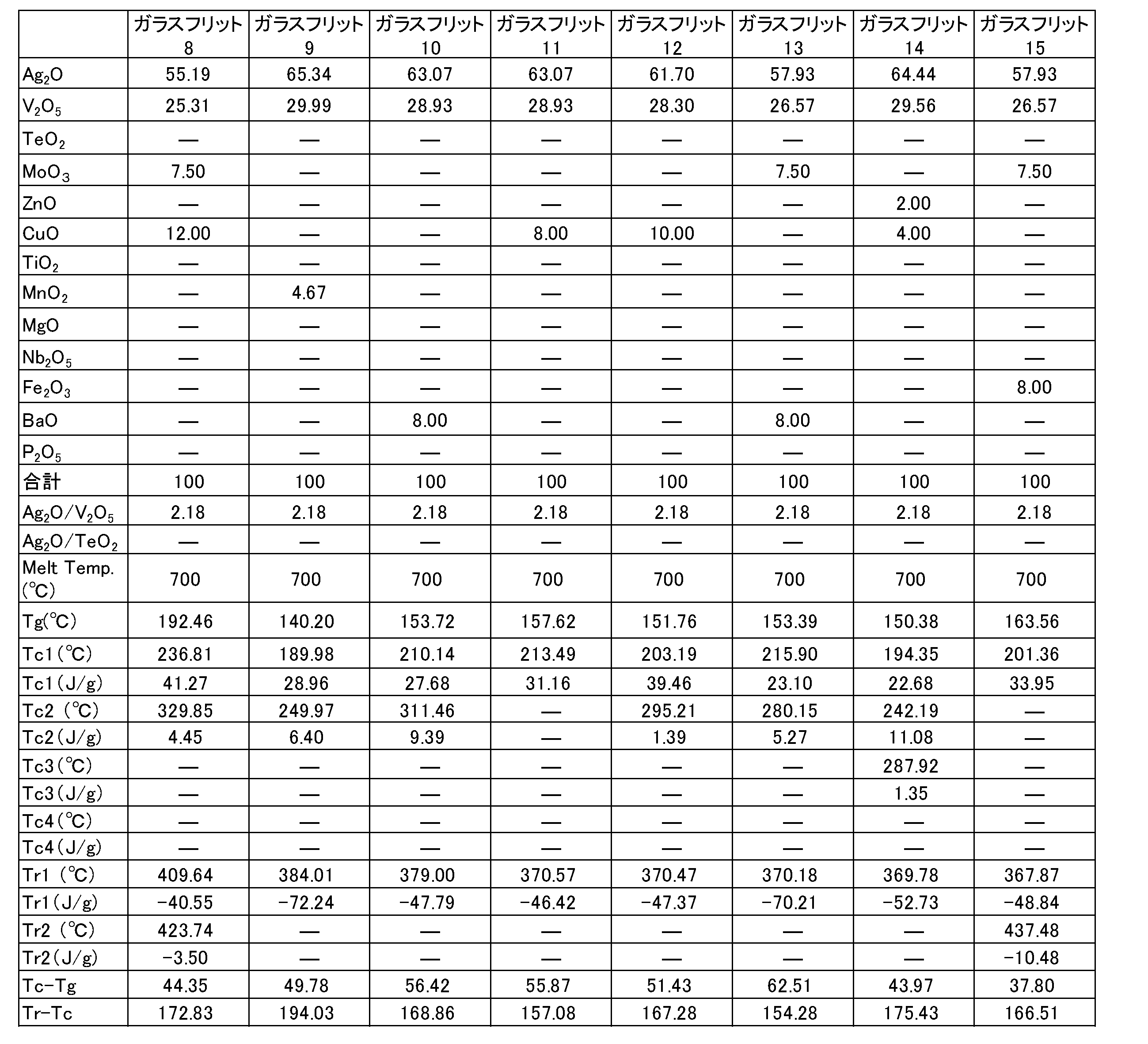
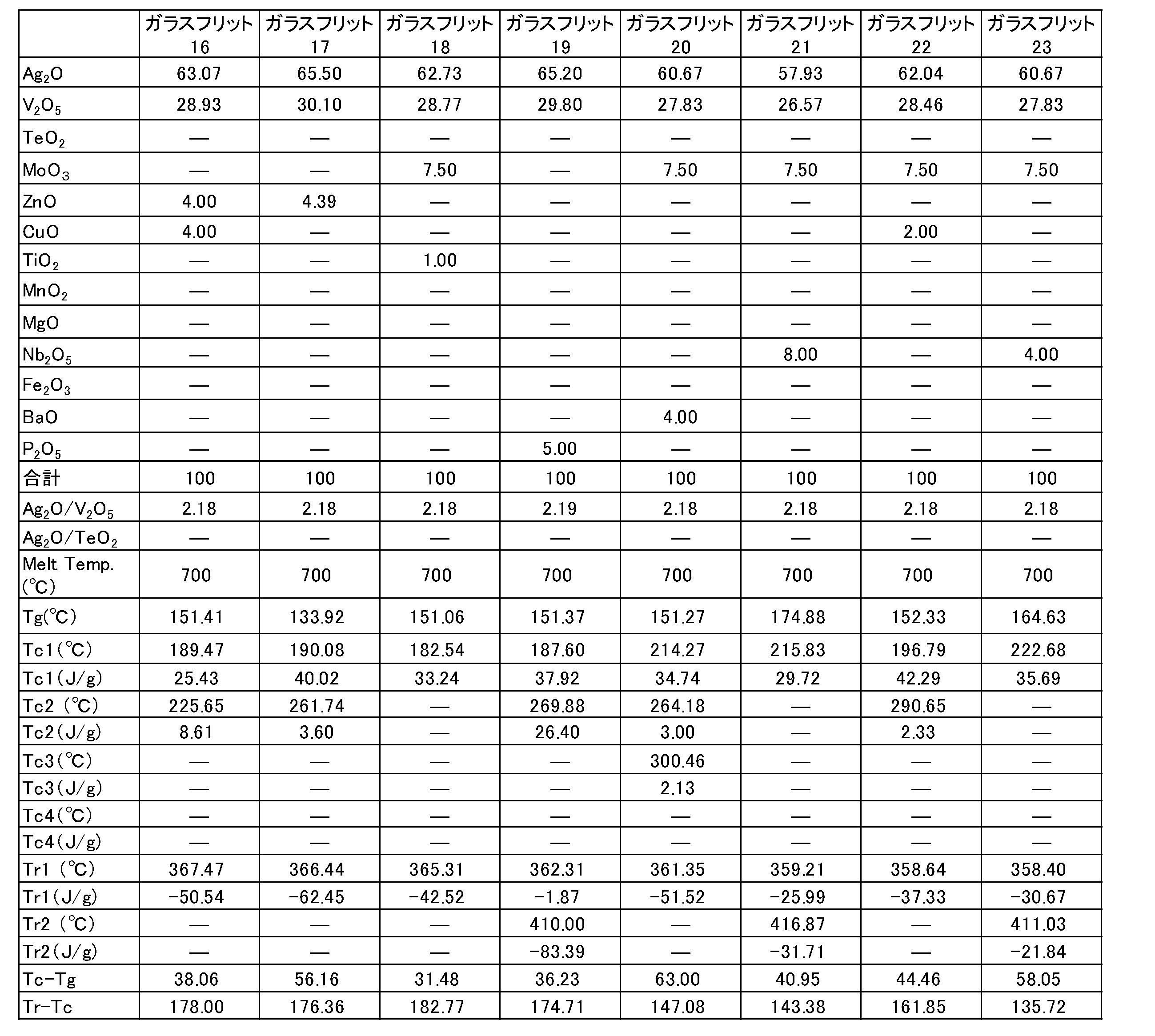
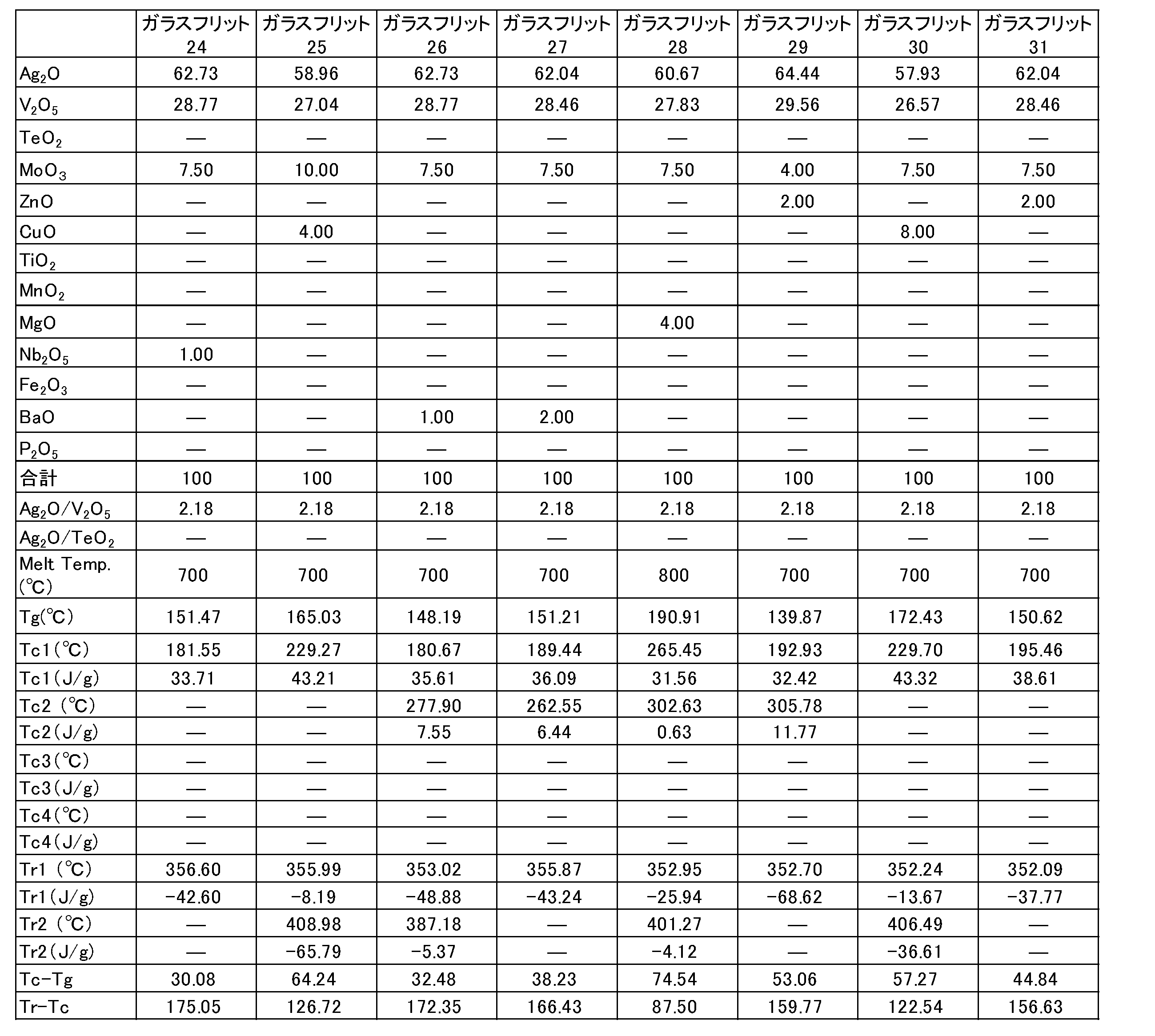
- Tables 2 to 7 show the composition of each component of the crystallized glass frit 8 to 51.
- the crystallized glass frit 8 to 51 contains (A-1) Ag 2 O and (A-2) V 2 O 5 , and further includes TeO 2 , MoO 3 , ZnO, CuO, TiO 2 , MnO 2 , MgO, As shown in Tables 2 to 7, at least one selected from Nb 2 O 5 , Fe 2 O 3 , BaO, and P 2 O 5 is included.
- the unit of the numerical value of each component of the crystallized glass frit in Tables 2 to 7 is mass%.
- the molten crystallized glass frit raw material was taken out of the oven together with the crucible, and the molten crystallized glass frit raw material was uniformly stirred.
- the molten crystallized glass frit raw material is then placed on a stainless steel 1.86 inch diameter roll rotating at room temperature, and the two rolls are mounted on a motor (BODUNE.D, C It was rotated with MOTOR 115V).
- the raw material of the melted crystallized glass frit was rapidly cooled at room temperature while being kneaded to form a plate-like glass. Finally, the plate-like glass was crushed with a mortar.
- DSC curves were measured for each crystallized glass frit 1 to 51 using a differential scanning calorimeter under the following conditions.
- Glass transition temperature (Tg), crystallization temperature (Tc), and remelting temperature (Tr) were measured from a DSC curve by differential scanning calorimetry.
- Tables 1 to 7 show the glass transition temperature (Tg), crystallization temperature (Tc), and remelting temperature (Tr) of each crystallized glass frit.
- FIG. 1 shows a DSC curve of the crystallized glass frit 1.
- FIG. 2 shows a DSC curve of the crystallized glass frit 7.
- Glass transition temperature (Tg) Using a differential scanning calorimeter DSC-50 manufactured by SHIMADZU, the crystallized glass frit is heated up to 3780 ° C. at a heating rate of 15 ° C./min, and a DSC curve in a temperature range of about 50 ° C. to about 370 ° C. is measured. did.
- the glass transition temperature (Tg) was the temperature at the first inflection point of the DSC curve.
- the crystallization temperature (Tc) is a calorific value of exothermic heat of 15 J in a DSC curve shown by a differential scanning calorimeter (DSC-50 manufactured by SHIMADZU) at a temperature increase rate of 15 ° C./min up to 370 ° C.
- the peak top temperature (° C.) of the first exothermic peak is Tc1
- the peak top temperature (° C.) of the second exothermic peak is Tc2
- the peak top of the third exothermic peak is set.
- the temperature (° C.) was Tc3
- the peak top temperature (° C.) of the fourth exothermic peak was Tc4.
- size of each peak was shown with the numerical value of the emitted-heat amount (J / g).
- the remelting temperature (Tr) is the lowest temperature in the DSC curve shown by the differential scanning calorimeter (DSC-50 manufactured by SHIMADZU) at a temperature rising rate of 15 ° C./min up to 370 ° C. The temperature was indicated by the peak top of the endothermic peak.
- the peak top temperature (° C.) of the first endothermic peak was Tr1
- the peak top temperature (° C.) of the second endothermic peak was Tr2.
- size of each peak was shown with the numerical value of the endothermic amount (J / g).
- the crystallization temperature (Tc) of the crystallized glass frit 1 used in the examples was 231.9 ° C. at Tc1 (a calorific value of 46.7 J / g).
- the crystallization temperature of the crystallized glass frit 2 used in the comparative example was set to a temperature of 185.4 ° C. at Tc1 (a calorific value of 27.1 J / g).
- glass paste 1 used for the manufacturing method of the example and glass paste 2 used for the manufacturing method of the comparative example were prepared.
- the material of the glass paste is as follows.
- Table 8 shows the composition of glass pastes 1 and 2 used in Examples and Comparative Examples.
- Conductive particles Ag, spherical, BET value 0.6 m 2 / g, average particle diameter D50: 6.4 ⁇ m, 6 g (71.59% by mass with respect to 100% by mass of glass paste), trade name: EA-0001
- the average particle diameter of the conductive particles is D50 (median) of the volume cumulative distribution measured using a laser diffraction / scattering particle diameter / particle size distribution measuring device (for example, MICROTRAC HRA9320-X100 manufactured by Nikkiso Co., Ltd.). Diameter).
- Crystallized glass frit 1 and 7 Each crystallized glass frit was obtained by pulverizing one type of glass frit in a mortar and classifying it using a 325 mesh sieve. The average particle diameter (D50) classified by sieving of the crystallized glass frit is about 13 ⁇ m to about 20 ⁇ m.
- the glass paste material having the composition shown in Table 8 was kneaded by a three-roll mill to produce a glass paste.
- the first adherend used an alumina plate having a length of 20 mm, a width of 20 mm, and a thickness of 1 mm as a substrate.
- a Si chip of 5 mm length ⁇ 5 mm width ⁇ 330 ⁇ m thickness was used.
- a spacer Using a spacer, a load was applied on the Si chip so that the thickness of the glass paste 1 interposed between the first adherend and the second adherend was 30 ⁇ m.
- the alumina plate and the Si chip with the glass paste 1 interposed were heated at 370 ° C. for 15 minutes.
- the heating temperature of 370 ° C. is a temperature at which the crystallization temperature (Tc1) of the crystallized glass frit 1 contained in the glass paste 1 is 231.9 ° C.
- test joined bodies 1 to 5 were obtained in the same manner as in the Examples.
- the heating temperature 370 ° C. is equal to or higher than the crystallization temperature (Tc1) 185.4 ° C. of the crystallized glass frit 7 included in the glass paste 2 and the remelting temperature (Tr1) 313.2 ° C. or higher.
- the test bonded bodies 1 to 5 obtained by the manufacturing method of the comparative example were prepared by combining the first adherend and the second adherend bonded with the glass paste interposed therebetween.
- (A) Crystallized glass frit crystals The step of heating to a temperature not lower than the remelting temperature (Tr) is not satisfied.
- Shear test (adhesion strength)
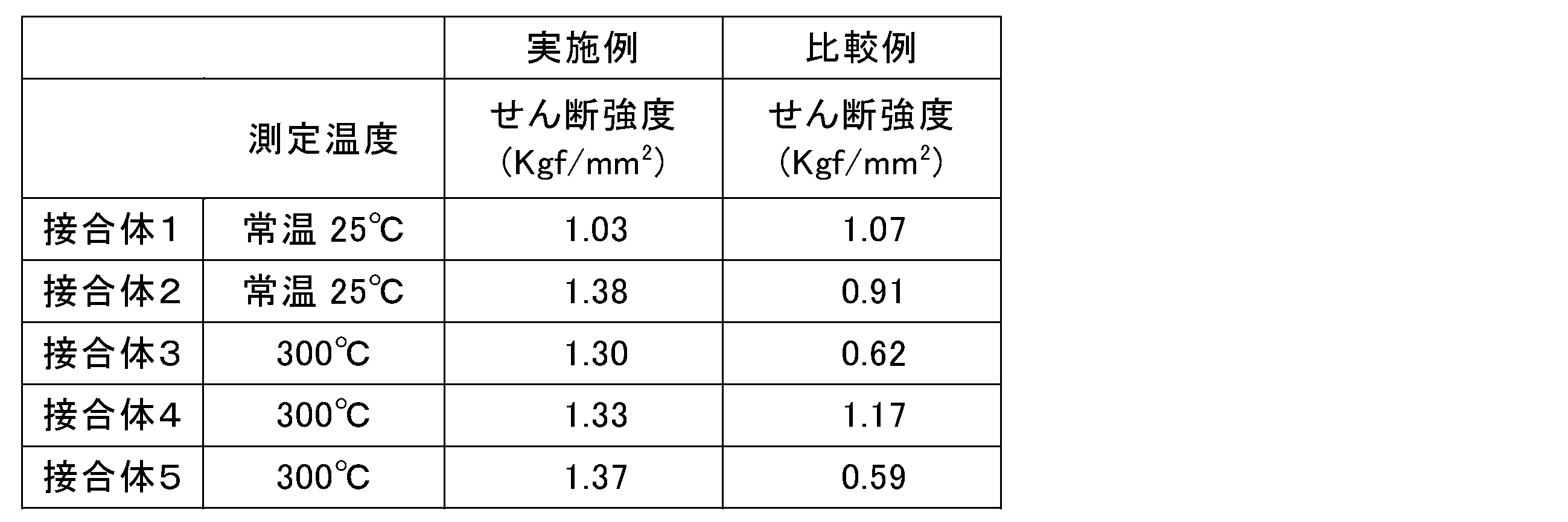
- the test joints 1 and 2 of the examples and comparative examples were placed in an environment at room temperature of 25 ° C., and after 30 seconds, a shear strength test was performed at a shear rate of 12 mm / min using a desktop strength tester 1605HTP manufactured by Aiko Engineering. The shear strength (Kgf / mm 2 ) was measured.
- test joints 3 to 5 were placed in an environment of 300 ° C., and after 30 seconds, a shear strength test was performed with a desktop strength tester 1605HTP manufactured by Aiko Engineering Co., Ltd. at a shear rate of 12 mm / min. Kgf / mm 2 ) was measured. The results are shown in Table 9 and FIG.
- the joined bodies 1 and 2 obtained by the manufacturing method of the example placed in an environment of room temperature 25 ° C. have the same or superior shear strength as the joined bodies 1 and 2 of the comparative example. Indicated. Further, as shown in FIG. 3 and Table 9, the joined bodies 3 to 5 obtained by the manufacturing method of the example installed in an environment of 300 ° C. are more than the joined bodies 3 to 5 obtained by the manufacturing method of the comparative example. Both showed excellent shear strength. From this result, the joined bodies 1 to 5 obtained by the production method of the present invention were obtained by using (A) crystallized glass frit crystals for the first adherend and the second adherend with the glass paste interposed therebetween.
- the first adherend and the second adherend are joined at a relatively low temperature, for example, a heating temperature of 450 ° C. or less, by the step of heating to a temperature equal to or higher than the recrystallization temperature (Tc) and lower than the remelting temperature (Tr). It was possible to confirm that it exhibited excellent heat resistance after joining. In particular, it was confirmed that the joined bodies 3 to 5 obtained by the production method of the present invention exhibited particularly excellent heat resistance when placed in a relatively high temperature environment of 300 ° C.
- the first adherend and the second adherend can be joined at a relatively low temperature, for example, a heating temperature of 450 ° C. or less. Can be obtained.
- a bonded body such as a semiconductor device in which a substrate and a semiconductor chip are bonded, A semiconductor package in which a substrate and a lid are bonded, an electronic package such as a SWA device, a bonded device such as a MEMS device, a high-frequency module, and a bonded device such as a semiconductor device in which a substrate or a semiconductor chip and a heat dissipation member are bonded are manufactured.
- a relatively low temperature for example, a heating temperature of 450 ° C. or less.
Landscapes
- Chemical & Material Sciences (AREA)
- Engineering & Computer Science (AREA)
- Materials Engineering (AREA)
- Chemical Kinetics & Catalysis (AREA)
- General Chemical & Material Sciences (AREA)
- Geochemistry & Mineralogy (AREA)
- Life Sciences & Earth Sciences (AREA)
- Organic Chemistry (AREA)
- Ceramic Engineering (AREA)
- Crystallography & Structural Chemistry (AREA)
- Dispersion Chemistry (AREA)
- Glass Compositions (AREA)
- Cooling Or The Like Of Semiconductors Or Solid State Devices (AREA)
- Die Bonding (AREA)
Abstract
Description
本発明において、ガラスペーストに含まれる(A)結晶化ガラスフリットは、体積基準の平均粒子径(メジアン径)が、好ましくは1~200μmの粉末ガラスである。結晶化ガラスフリットの平均粒子径は、より好ましくは3~180μm、さらに好ましくは3~160μm、特に好ましくは5~150μmである。(A)結晶化ガラスフリットは、次のようにして得ることができる。すなわち、原料を磁性るつぼに入れ、熔融炉(オーブン)内で加熱溶融してガラス融液を得る。次に、このガラス融液をステンレス製のローラー間に流し入れて、シート状に成形する。得られたシート状ガラスを、乳鉢で粉砕し、例えば100メッシュ及び200メッシュの試験ふるいでふるい分級する。以上のようにして、(A)結晶化ガラスフリットを得ることができる。試験ふるいのメッシュの大きさは特に限定されない。細かいメッシュの試験ふるいを用いてふるい分級することによって、より平均粒子径(メジアン径)の小さい結晶化ガラスフリットを得ることができる。結晶化ガラスフリットの平均粒子径は、レーザー回折・散乱式粒子径・粒度分布測定装置(例えば、日機装社製、MICROTRAC HRA9320-X100)を用いて測定することができる。結晶化ガラスフリットの平均粒子径は、体積累積分布D50(メジアン径)をいう。
本発明の方法に用いるガラスペーストは、(B)溶剤を含む。(B)溶剤としては、アルコール類(例えばテルピネオール、α-テルピネオール、β-テルピネオール等)、エステル類(例えばヒドロキシ基含有エステル類、2,2,4―トリメチル-1,3-ペンタンジオールモノイソブチラート、ブチルカルビトールアセテート等)、パラフィン混合物(例えばCondea社製のLinpar)、多価アルコール類(例えば2-エチル-1,3-ヘキサンジオール)から1種又は2種以上を選択して使用することができる。
本発明の方法に用いるガラスペーストは、(C)導電性粒子を含むことが好ましい。(C)導電性粒子は、例えば銀(Ag)、銅(Cu)、ニッケル(Ni)及び銀(Ag)と卑金属(例えば、Cu及びNi等)との銀合金等を用いることができる。中でも、導電性粒子が銀(Ag)であることが好ましい。
本発明の方法に用いるガラスペーストは、さらに(D)金属酸化物を含んでいてもよい。金属酸化物は、SnO、ZnO、In2O3及びCuOからなる群より選ばれる少なくとも1種の金属酸化物が挙げられる。この金属酸化物は、ガラスフリットに含まれている酸化物ではない。
本発明の方法に用いるガラスペーストは、その他の添加剤として、可塑剤、消泡剤、分散剤、レベリング剤、安定剤、及び密着促進剤などから選択したものを、必要に応じてさらに配合することができる。これらのうち、可塑剤としては、フタル酸エステル類、グリコール酸エステル類、リン酸エステル類、セバシン酸エステル類、アジピン酸エステル類、及びクエン酸エステル類等から選択したものを用いることができる。
本発明の方法に用いるガラスペーストは、(A)結晶化ガラスフリットと、(B)溶剤とを含む。ガラスペースト中の(A)結晶化ガラスフリットの配合は特に限定されない。(A)結晶化ガラスフリットは、ガラスペースト100質量%中、好ましくは50~99質量%、より好ましくは65~95質量%、さらに好ましくは75~95質量%含む。ガラスペースト中の(B)溶剤の配合は特に限定されない。(B)溶剤は、ガラスペースト100質量%中、好ましくは1~50質量%、より好ましくは5~40質量%、さらに好ましくは5~30質量%含む。
本発明の方法に用いるガラスペーストは、(A)結晶化ガラスフリットと、(B)溶剤とを混合する工程を有する。ガラスペーストが、(C)導電性粒子、(D)金属酸化物、場合によりその他の添加剤及び/又は添加粒子を含む場合には、例えば(B)溶剤に対して、(A)結晶化ガラスフリットを添加し、場合により、(C)導電性粒子、(D)金属酸化物、並びにその他の添加剤及び/又は添加粒子を、添加し、混合し、分散することにより製造することができる。
本発明の方法によって接合される第一の被着体及び/又は第二の被着体は、例えば、基板、半導体チップ、蓋体、放熱部材等が挙げられる。
本発明の接合体の製造方法は、(A)結晶化ガラスフリットと、(B)溶剤とを含み、(A)結晶化ガラスフリットが、ガラス転移温度(Tg)と、結晶化温度(Tc)と、再溶融温度(Tr)とを有し、再溶融温度(Tr)が結晶化温度(Tc)を超える温度であり、結晶化温度(Tc)がガラス転移温度(Tg)を超える温度であるガラスペーストを用いる。本発明の接合体の製造方法は、第一の被着体及び/又は第二の被着体にガラスペーストを塗布する工程を含む。本発明の接合体の製造方法は、ガラスペーストを介在させて第一の被着体と第二の被着体を接合する工程を含む。本発明の接合体の製造方法は、ガラスペーストを介在させて接合した第一の被着体と第二の被着体を、(A)結晶化ガラスフリットの結晶化温度(Tc)以上再溶融温度(Tr)未満に加熱する工程を含む。ガラスペーストを介在させて接合した第一の被着体と第二の被着体を結晶化ガラスフリットのガラス転移温度以下に冷却して接合体を得る工程を含む。
表1は、結晶化ガラスフリット1~7の各成分の配合を示す。結晶化ガラスフリット1は、本発明の実施例の製造方法に用いた。結晶化ガラスフリット1は、(A-1)Ag2O、(A-2)V2O5、(A-3)MoO3、及び(A-4)CuOから実質的に成る。結晶化ガラスフリット7は、比較例の製造方法に用いた。結晶化ガラスフリット7は、(a-1)Ag2O、(a-2)V2O5、及び(a-3)TeO2から実質的に成る。結晶化ガラスフリット2~6は、Ag2OとTeO2を各配合で含み、V2O5を含まない。表1中の結晶化ガラスフリットの各成分の数値の単位は、質量%である。
表2~7は、結晶化ガラスフリット8~51の各成分の配合を示す。結晶化ガラスフリット8~51は、(A-1)Ag2O、及び(A-2)V2O5を含み、さらにTeO2、MoO3、ZnO、CuO、TiO2、MnO2、MgO、Nb2O5、Fe2O3、BaO、及びP2O5から選択される少なくとも1種を表2~7に示すように含む。表2~7中の結晶化ガラスフリットの各成分の数値の単位は、質量%である。
SHIMADZU社製の示差走査熱量計DSC-50を用いて、結晶化ガラスフリットを昇温速度15℃/minで3780℃まで昇温し、約50℃~約370℃の温度領域のDSC曲線を測定した。ガラス転移温度(Tg)は、DSC曲線の最初の変曲点の温度とした。
結晶化温度(Tc)は、示差走査熱量計(SHIMADZU社製のDSC-50)にて、昇温速度15℃/minで370℃まで昇温した条件によって示されるDSC曲線において、発熱の熱量15J/g以上の少なくとも1つの発熱ピークのピークトップによって示される温度とした。発熱ピークが複数ある場合には、最初の発熱ピークのピークトップの温度(℃)をTc1とし、2番目の発熱ピークのピークトップの温度(℃)をTc2とし、3番目の発熱ピークのピークトップの温度(℃)をTc3とし、4番目の発熱ピークのピークトップの温度(℃)をTc4とした。また、各ピークの大きさは、発熱量(J/g)の数値で示した。
再溶融温度(Tr)は、示差走査熱量計(SHIMADZU社製のDSC-50)にて、昇温速度15℃/minで370℃まで昇温した条件によって示されるDSC曲線において、最も温度の低い吸熱ピークのピークトップによって示される温度とした。吸熱ピークが複数ある場合には、最初の吸熱ピークのピークトップの温度(℃)をTr1とし、2番目の吸熱ピークのピークトップの温度(℃)を、Tr2とした。また、各ピークの大きさは、吸熱量(J/g)の数値で示した。




ガラスペーストの材料は、下記の通りである。表8に、実施例及び比較例に用いるガラスペースト1及び2の配合を示す。
・溶剤:テルピネオール:0.88g(ALDRICH社製 品番:Terpineol、導電性ペースト100質量%に対して10.48質量%)
・結晶化ガラスフリット1及び7:各結晶化ガラスフリットは、1種類のガラスフリットを乳鉢にて粉砕し、325メッシュのふるいを用いて、ふるい分級したものを用いた。結晶化ガラスフリットのふるい分級した平均粒子径(D50)は、約13μm~約20μmである。

表8に示す組成のガラスペーストの材料を三本ロールミルにて混練し、ガラスペーストを作製した。
第一の被着体は、基板として縦20mm×横20mm×厚さ1mmのアルミナ板を用いた。第二の被着体は、縦5mm×横5mm×厚さ330μmのSiチップを用いた。
ガラスペースト2を用いたこと以外は、実施例と同様にして試験用の接合体1~5を得た。加熱温度370℃は、ガラスペースト2に含まれる結晶化ガラスフリット7の結晶化温度(Tc1)185.4℃以上であり、再溶融温度(Tr1)313.2℃以上である。比較例の製造方法によって得られた試験用の接合体1~5は、ガラスペーストを介在させて接合した第一の被着体と第二の被着体を(A)結晶化ガラスフリットの結晶化温度(Tc)以上再溶融温度(Tr)未満に加熱する工程を満たしていない。
実施例及び比較例の試験用の接合体1~2を常温25℃の環境に設置し、30秒後、アイコーエンジニアリング社製卓上強度試験機1605HTPにより、せん断速度12mm/分で、せん断強度試験を行い、せん断強度(Kgf/mm2)を測定した。
Claims (14)
- 第一の被着体と第二の被着体とをガラスペーストを用いて接合する接合体の製造方法であって、
ガラスペーストは、(A)結晶化ガラスフリットと、(B)溶剤とを含み、(A)結晶化ガラスフリットが、ガラス転移温度と結晶化温度と再溶融温度とを有し、再溶融温度が結晶化温度を超える温度であり、結晶化温度がガラス転移温度を超える温度であり、
第一の被着体及び/又は第二の被着体にガラスペーストを塗布する工程と、
ガラスペーストを介在させて第一の被着体と第二の被着体を接合する工程と、
ガラスペーストを介在させて接合した第一の被着体と第二の被着体を、(A)結晶化ガラスフリットの結晶化温度以上再溶融温度未満に加熱する工程と、
ガラスペーストを介在させて接合した第一の被着体と第二の被着体とを結晶化ガラスフリットのガラス転移温度以下に冷却して接合体を得る工程とを含む、接合体の製造方法。 - ガラスペーストが、さらに(C)導電性粒子を含む、請求項1記載の接合体の製造方法。
- (A)結晶化ガラスフリットの再溶融温度が300℃以上である、請求項1又は2記載の接合体の製造方法。
- (A)結晶化ガラスフリットのガラス転移温度と結晶化温度の差が30℃以上185℃以下である、請求項1~3のいずれか1項記載の接合体の接続方法。
- (A)結晶化ガラスフリットの結晶化温度が150℃以上350℃以下である、請求項1~4のいずれか1項記載の接合体の製造方法。
- (A)結晶化ガラスフリットのガラス転移温度が110℃以上200℃未満である、請求項1~5のいずれか1項記載の接合体の製造方法。
- (A)結晶化ガラスフリットが、Ag2O及びV2O5を含む、請求項1~6のいずれか1項記載の接合体の製造方法。
- (A)結晶化ガラスフリットが、TeO2、MoO3、MnO3、ZnO、CuO、TiO2、MgO、Nb2O5、BaO、Al2O3、SnO、及びFe2O3からなる群より選ばれる少なくとも1種の酸化物を含む、請求項7記載の接合体の製造方法。
- (A)結晶化ガラスフリットが、結晶化ガラスフリットの全質量に対して、酸化物換算で、(A-1)Ag2Oと(A-2)V2O5を合計量で80~96質量%含み、(A-2)V2O5に対する(A-1)Ag2Oの質量比(Ag2O/V2O5)が1.8~3.2である、請求項7又は8記載の導電性ペースト。
- (A)結晶化ガラスフリットが、Ag2O及びTeO2を含む、請求項1~6のいずれか1項記載の接合体の製造方法。
- (A)結晶化ガラスフリットが、MoO3、MnO3、ZnO、CuO、TiO2、MgO、Nb2O5、BaO、Al2O3、SnO、B2O3及びFe2O3からなる群より選ばれる少なくとも1種の酸化物を含む、請求項10記載の接合体の製造方法。
- 第一の被着体が基板であり、第二の被着体が半導体チップである、請求項1~11のいずれか1項記載の接合体の製造方法。
- 第一の被着体が基板であり、第二の被着体が蓋体である、請求項1~11のいずれか1項記載の接合体の製造方法。
- 第一の被着体が基板又は半導体チップであり、第二の被着体が放熱部材である、請求項1~11のいずれか1項記載の接合体の製造方法。
Priority Applications (3)
| Application Number | Priority Date | Filing Date | Title |
|---|---|---|---|
| US15/564,674 US10290601B2 (en) | 2015-04-09 | 2016-04-06 | Method of manufacturing bonded body |
| CN201680015200.1A CN107408514B (zh) | 2015-04-09 | 2016-04-06 | 接合体的制造方法 |
| JP2017511003A JP6679025B2 (ja) | 2015-04-09 | 2016-04-06 | 接合体の製造方法 |
Applications Claiming Priority (2)
| Application Number | Priority Date | Filing Date | Title |
|---|---|---|---|
| US201562145250P | 2015-04-09 | 2015-04-09 | |
| US62/145250 | 2015-04-09 |
Publications (1)
| Publication Number | Publication Date |
|---|---|
| WO2016163377A1 true WO2016163377A1 (ja) | 2016-10-13 |
Family
ID=57072323
Family Applications (1)
| Application Number | Title | Priority Date | Filing Date |
|---|---|---|---|
| PCT/JP2016/061195 Ceased WO2016163377A1 (ja) | 2015-04-09 | 2016-04-06 | 接合体の製造方法 |
Country Status (5)
| Country | Link |
|---|---|
| US (1) | US10290601B2 (ja) |
| JP (1) | JP6679025B2 (ja) |
| CN (1) | CN107408514B (ja) |
| TW (1) | TWI691580B (ja) |
| WO (1) | WO2016163377A1 (ja) |
Families Citing this family (1)
| Publication number | Priority date | Publication date | Assignee | Title |
|---|---|---|---|---|
| JP7739013B2 (ja) | 2021-03-05 | 2025-09-16 | キヤノン株式会社 | ホットメルト接着剤及び接着物の製造方法 |
Citations (4)
| Publication number | Priority date | Publication date | Assignee | Title |
|---|---|---|---|---|
| JPH1154531A (ja) * | 1997-07-31 | 1999-02-26 | Nec Kansai Ltd | セラミックパッケージ型圧電素子およびその製造方法 |
| JP2009026965A (ja) * | 2007-07-19 | 2009-02-05 | Nissan Motor Co Ltd | 電子部品、およびその製造方法 |
| JP2013151396A (ja) * | 2012-01-26 | 2013-08-08 | Hitachi Ltd | 接合体および半導体モジュール |
| WO2014119579A1 (ja) * | 2013-02-01 | 2014-08-07 | ナミックス株式会社 | ガラスフリット |
Family Cites Families (4)
| Publication number | Priority date | Publication date | Assignee | Title |
|---|---|---|---|---|
| US5334558A (en) | 1992-10-19 | 1994-08-02 | Diemat, Inc. | Low temperature glass with improved thermal stress properties and method of use |
| JP2011054531A (ja) * | 2009-09-04 | 2011-03-17 | National Institute Of Advanced Industrial Science & Technology | 酸化物超電導薄膜の製造方法および超電導線材 |
| JP5349694B2 (ja) * | 2010-07-02 | 2013-11-20 | 有限会社ソフィアプロダクト | 接合材 |
| US8709862B2 (en) * | 2011-01-06 | 2014-04-29 | Heraeus Precious Metals North America Conshohocken Llc | Vanadium, cobalt and strontium additives for use in aluminum back solar cell contacts |
-
2016
- 2016-04-06 WO PCT/JP2016/061195 patent/WO2016163377A1/ja not_active Ceased
- 2016-04-06 CN CN201680015200.1A patent/CN107408514B/zh active Active
- 2016-04-06 US US15/564,674 patent/US10290601B2/en active Active
- 2016-04-06 JP JP2017511003A patent/JP6679025B2/ja active Active
- 2016-04-08 TW TW105111028A patent/TWI691580B/zh active
Patent Citations (4)
| Publication number | Priority date | Publication date | Assignee | Title |
|---|---|---|---|---|
| JPH1154531A (ja) * | 1997-07-31 | 1999-02-26 | Nec Kansai Ltd | セラミックパッケージ型圧電素子およびその製造方法 |
| JP2009026965A (ja) * | 2007-07-19 | 2009-02-05 | Nissan Motor Co Ltd | 電子部品、およびその製造方法 |
| JP2013151396A (ja) * | 2012-01-26 | 2013-08-08 | Hitachi Ltd | 接合体および半導体モジュール |
| WO2014119579A1 (ja) * | 2013-02-01 | 2014-08-07 | ナミックス株式会社 | ガラスフリット |
Also Published As
| Publication number | Publication date |
|---|---|
| TWI691580B (zh) | 2020-04-21 |
| CN107408514A (zh) | 2017-11-28 |
| US10290601B2 (en) | 2019-05-14 |
| JP6679025B2 (ja) | 2020-04-15 |
| US20180082972A1 (en) | 2018-03-22 |
| CN107408514B (zh) | 2020-04-14 |
| JPWO2016163377A1 (ja) | 2018-02-01 |
| TW201641644A (zh) | 2016-12-01 |
Similar Documents
| Publication | Publication Date | Title |
|---|---|---|
| JP6560684B2 (ja) | 導電性ペースト及びそれを用いた半導体装置の製造方法 | |
| KR102066300B1 (ko) | 땜납 접합 구조, 파워 모듈, 히트 싱크가 형성된 파워 모듈용 기판 및 그것들의 제조 방법, 그리고 땜납 하지층 형성용 페이스트 | |
| TWI489594B (zh) | And the semiconductor module | |
| US9776909B2 (en) | Glass frit | |
| US9693449B2 (en) | Power module substrate, power module substrate with metal part, power module with metal part, method for producing power module substrate, and method for producing power module substrate with metal part | |
| CN104072187A (zh) | 接合材料和接合构造体 | |
| CN106536437B (zh) | 散热结构体及利用了散热结构体的半导体模块 | |
| JP6679025B2 (ja) | 接合体の製造方法 | |
| WO2018139209A1 (ja) | 接合材及び接合体 | |
| JP2013168240A (ja) | はんだ下地層形成用ペースト | |
| WO2016175146A1 (ja) | 導電性接合体および該接合体の製造方法 | |
| JP2014125356A (ja) | 導体形成用無鉛ガラス組成物と導体形成用組成物 |
Legal Events
| Date | Code | Title | Description |
|---|---|---|---|
| 121 | Ep: the epo has been informed by wipo that ep was designated in this application |
Ref document number: 16776543 Country of ref document: EP Kind code of ref document: A1 |
|
| ENP | Entry into the national phase |
Ref document number: 2017511003 Country of ref document: JP Kind code of ref document: A |
|
| WWE | Wipo information: entry into national phase |
Ref document number: 15564674 Country of ref document: US |
|
| NENP | Non-entry into the national phase |
Ref country code: DE |
|
| 122 | Ep: pct application non-entry in european phase |
Ref document number: 16776543 Country of ref document: EP Kind code of ref document: A1 |