WO2016163161A1 - 単結晶引き上げ用種結晶保持具及びこれを用いたシリコン単結晶の製造方法 - Google Patents
単結晶引き上げ用種結晶保持具及びこれを用いたシリコン単結晶の製造方法 Download PDFInfo
- Publication number
- WO2016163161A1 WO2016163161A1 PCT/JP2016/054653 JP2016054653W WO2016163161A1 WO 2016163161 A1 WO2016163161 A1 WO 2016163161A1 JP 2016054653 W JP2016054653 W JP 2016054653W WO 2016163161 A1 WO2016163161 A1 WO 2016163161A1
- Authority
- WO
- WIPO (PCT)
- Prior art keywords
- seed crystal
- carbon fiber
- crystal holder
- core
- central axis
- Prior art date
- Legal status (The legal status is an assumption and is not a legal conclusion. Google has not performed a legal analysis and makes no representation as to the accuracy of the status listed.)
- Ceased
Links
Images





Classifications
-
- C—CHEMISTRY; METALLURGY
- C30—CRYSTAL GROWTH
- C30B—SINGLE-CRYSTAL GROWTH; UNIDIRECTIONAL SOLIDIFICATION OF EUTECTIC MATERIAL OR UNIDIRECTIONAL DEMIXING OF EUTECTOID MATERIAL; REFINING BY ZONE-MELTING OF MATERIAL; PRODUCTION OF A HOMOGENEOUS POLYCRYSTALLINE MATERIAL WITH DEFINED STRUCTURE; SINGLE CRYSTALS OR HOMOGENEOUS POLYCRYSTALLINE MATERIAL WITH DEFINED STRUCTURE; AFTER-TREATMENT OF SINGLE CRYSTALS OR A HOMOGENEOUS POLYCRYSTALLINE MATERIAL WITH DEFINED STRUCTURE; APPARATUS THEREFOR
- C30B15/00—Single-crystal growth by pulling from a melt, e.g. Czochralski method
- C30B15/32—Seed holders, e.g. chucks
-
- B—PERFORMING OPERATIONS; TRANSPORTING
- B32—LAYERED PRODUCTS
- B32B—LAYERED PRODUCTS, i.e. PRODUCTS BUILT-UP OF STRATA OF FLAT OR NON-FLAT, e.g. CELLULAR OR HONEYCOMB, FORM
- B32B18/00—Layered products essentially comprising ceramics, e.g. refractory products
-
- C—CHEMISTRY; METALLURGY
- C04—CEMENTS; CONCRETE; ARTIFICIAL STONE; CERAMICS; REFRACTORIES
- C04B—LIME, MAGNESIA; SLAG; CEMENTS; COMPOSITIONS THEREOF, e.g. MORTARS, CONCRETE OR LIKE BUILDING MATERIALS; ARTIFICIAL STONE; CERAMICS; REFRACTORIES; TREATMENT OF NATURAL STONE
- C04B35/00—Shaped ceramic products characterised by their composition; Ceramics compositions; Processing powders of inorganic compounds preparatory to the manufacturing of ceramic products
- C04B35/71—Ceramic products containing macroscopic reinforcing agents
- C04B35/78—Ceramic products containing macroscopic reinforcing agents containing non-metallic materials
- C04B35/80—Fibres, filaments, whiskers, platelets, or the like
- C04B35/83—Carbon fibres in a carbon matrix
-
- C—CHEMISTRY; METALLURGY
- C30—CRYSTAL GROWTH
- C30B—SINGLE-CRYSTAL GROWTH; UNIDIRECTIONAL SOLIDIFICATION OF EUTECTIC MATERIAL OR UNIDIRECTIONAL DEMIXING OF EUTECTOID MATERIAL; REFINING BY ZONE-MELTING OF MATERIAL; PRODUCTION OF A HOMOGENEOUS POLYCRYSTALLINE MATERIAL WITH DEFINED STRUCTURE; SINGLE CRYSTALS OR HOMOGENEOUS POLYCRYSTALLINE MATERIAL WITH DEFINED STRUCTURE; AFTER-TREATMENT OF SINGLE CRYSTALS OR A HOMOGENEOUS POLYCRYSTALLINE MATERIAL WITH DEFINED STRUCTURE; APPARATUS THEREFOR
- C30B15/00—Single-crystal growth by pulling from a melt, e.g. Czochralski method
- C30B15/007—Pulling on a substrate
-
- C—CHEMISTRY; METALLURGY
- C30—CRYSTAL GROWTH
- C30B—SINGLE-CRYSTAL GROWTH; UNIDIRECTIONAL SOLIDIFICATION OF EUTECTIC MATERIAL OR UNIDIRECTIONAL DEMIXING OF EUTECTOID MATERIAL; REFINING BY ZONE-MELTING OF MATERIAL; PRODUCTION OF A HOMOGENEOUS POLYCRYSTALLINE MATERIAL WITH DEFINED STRUCTURE; SINGLE CRYSTALS OR HOMOGENEOUS POLYCRYSTALLINE MATERIAL WITH DEFINED STRUCTURE; AFTER-TREATMENT OF SINGLE CRYSTALS OR A HOMOGENEOUS POLYCRYSTALLINE MATERIAL WITH DEFINED STRUCTURE; APPARATUS THEREFOR
- C30B29/00—Single crystals or homogeneous polycrystalline material with defined structure characterised by the material or by their shape
- C30B29/02—Elements
- C30B29/06—Silicon
-
- C—CHEMISTRY; METALLURGY
- C04—CEMENTS; CONCRETE; ARTIFICIAL STONE; CERAMICS; REFRACTORIES
- C04B—LIME, MAGNESIA; SLAG; CEMENTS; COMPOSITIONS THEREOF, e.g. MORTARS, CONCRETE OR LIKE BUILDING MATERIALS; ARTIFICIAL STONE; CERAMICS; REFRACTORIES; TREATMENT OF NATURAL STONE
- C04B2235/00—Aspects relating to ceramic starting mixtures or sintered ceramic products
- C04B2235/02—Composition of constituents of the starting material or of secondary phases of the final product
- C04B2235/50—Constituents or additives of the starting mixture chosen for their shape or used because of their shape or their physical appearance
- C04B2235/52—Constituents or additives characterised by their shapes
- C04B2235/5208—Fibers
- C04B2235/5268—Orientation of the fibers
-
- C—CHEMISTRY; METALLURGY
- C04—CEMENTS; CONCRETE; ARTIFICIAL STONE; CERAMICS; REFRACTORIES
- C04B—LIME, MAGNESIA; SLAG; CEMENTS; COMPOSITIONS THEREOF, e.g. MORTARS, CONCRETE OR LIKE BUILDING MATERIALS; ARTIFICIAL STONE; CERAMICS; REFRACTORIES; TREATMENT OF NATURAL STONE
- C04B2237/00—Aspects relating to ceramic laminates or to joining of ceramic articles with other articles by heating
- C04B2237/30—Composition of layers of ceramic laminates or of ceramic or metallic articles to be joined by heating, e.g. Si substrates
- C04B2237/32—Ceramic
- C04B2237/38—Fiber or whisker reinforced
- C04B2237/385—Carbon or carbon composite
-
- C—CHEMISTRY; METALLURGY
- C04—CEMENTS; CONCRETE; ARTIFICIAL STONE; CERAMICS; REFRACTORIES
- C04B—LIME, MAGNESIA; SLAG; CEMENTS; COMPOSITIONS THEREOF, e.g. MORTARS, CONCRETE OR LIKE BUILDING MATERIALS; ARTIFICIAL STONE; CERAMICS; REFRACTORIES; TREATMENT OF NATURAL STONE
- C04B2237/00—Aspects relating to ceramic laminates or to joining of ceramic articles with other articles by heating
- C04B2237/50—Processing aspects relating to ceramic laminates or to the joining of ceramic articles with other articles by heating
- C04B2237/76—Forming laminates or joined articles comprising at least one member in the form other than a sheet or disc, e.g. two tubes or a tube and a sheet or disc
- C04B2237/765—Forming laminates or joined articles comprising at least one member in the form other than a sheet or disc, e.g. two tubes or a tube and a sheet or disc at least one member being a tube
-
- C—CHEMISTRY; METALLURGY
- C04—CEMENTS; CONCRETE; ARTIFICIAL STONE; CERAMICS; REFRACTORIES
- C04B—LIME, MAGNESIA; SLAG; CEMENTS; COMPOSITIONS THEREOF, e.g. MORTARS, CONCRETE OR LIKE BUILDING MATERIALS; ARTIFICIAL STONE; CERAMICS; REFRACTORIES; TREATMENT OF NATURAL STONE
- C04B2237/00—Aspects relating to ceramic laminates or to joining of ceramic articles with other articles by heating
- C04B2237/50—Processing aspects relating to ceramic laminates or to the joining of ceramic articles with other articles by heating
- C04B2237/84—Joining of a first substrate with a second substrate at least partially inside the first substrate, where the bonding area is at the inside of the first substrate, e.g. one tube inside another tube
Definitions
- the present invention relates to a single crystal pulling seed crystal holder, and more particularly to a single crystal pulling seed crystal holder used when a silicon single crystal is manufactured by the Czochralski method (hereinafter referred to as CZ method). .
- the present invention also relates to a method for producing a silicon single crystal using such a seed crystal holder.
- Patent Document 1 proposes a seed crystal holder made of carbon fiber cloth reinforced graphite.
- This seed crystal holder has a structure in which carbon fibers are wound in the circumferential direction at least in the lower outer peripheral portion, and the carbon fibers are arranged in the vertical direction in other portions.
- Patent Documents 2 and 3 propose a method of holding a seed crystal without breaking it by interposing a cushioning material between the tapered portion of the seed crystal and the surface of the seed crystal holder.
- Patent Document 4 discloses a material in which a pyrolytic carbon film is formed on the surface of a seed crystal holder made of a carbon fiber reinforced composite material, thereby suppressing SiC reaction and improving durability. ing.
- the inner peripheral surface S of the seed crystal holder 8 is shown in FIG. 1 is likely to occur deformation of the inner peripheral surface S 1 in the a portion and the C portion is parallel to the direction of the carbon fiber 8f, but a small compressive stress applied to the outer peripheral surface of the seed crystal, the inner peripheral surface of the seed crystal holder 8 S 1 is the deformation of the inner peripheral surface S 1 is less likely to occur in the B part and the part D which is substantially perpendicular to the direction of the carbon fiber 8f, a large compressive stress applied to the outer peripheral surface of the seed crystal.
- the problem of seed crystal breakage due to stress concentration is a new problem that has become apparent with the pulling of a 450 mm diameter silicon single crystal.
- the crystal weight In the pulling of a silicon single crystal having a diameter of 300 mm, where the crystal weight is not so large, the seed crystal was hardly broken at the portion in contact with the seed crystal holder.
- the crystal weight may exceed 1000 kg, and the above problem has become conspicuous due to the increase in the weight of the single crystal, and an early solution is desired.
- a seed crystal holder is made of a carbon fiber reinforced carbon composite material, and has a substantially cylindrical shape having a hollow portion having a shape that matches the outer shape of a substantially rod-shaped seed crystal.
- a seed crystal holder for pulling a single crystal characterized in that at least a portion of the carbon fiber in contact with the outer peripheral surface of the seed crystal is isotropic when viewed from the central axis of the hollow portion.
- the direction of the carbon fiber in the portion in contact with the outer peripheral surface of the seed crystal has a circumferential component. According to this configuration, since the entire circumference of the inner peripheral surface of the hollow portion of the seed crystal holder is parallel to the direction of the carbon fiber in the horizontal section, the fiber structure of the carbon fiber can be made isotropic.
- the direction of the carbon fiber in a portion in contact with the outer peripheral surface of the seed crystal further has a component parallel to the central axis.
- the carbon fiber since the carbon fiber includes a fiber component parallel to the axial direction, such as when the carbon fiber is wound obliquely in a diagonal shape, the tensile strength in the axial direction of the seed crystal holder can be increased. .
- the seed crystal has a tapered portion with a gradually decreasing diameter
- the hollow portion has an inner peripheral surface that comes into surface contact with the tapered portion, and the portion of the inner peripheral surface that constitutes the inner peripheral surface
- the direction of the carbon fiber is isotropic as viewed from the central axis of the hollow portion.
- the carbon fiber direction of the entire seed crystal holder is preferably isotropic as viewed from the central axis of the hollow portion. According to this structure, since the structure is simple, it can be manufactured easily.
- the direction of the carbon fiber other than the portion in contact with the outer peripheral surface of the seed crystal has anisotropy when viewed from the central axis of the hollow portion. According to this configuration, the tensile strength in the axial direction can be increased, and the mechanical strength of the seed crystal holder can be improved.
- the seed crystal holder according to the second aspect of the present invention comprises a substantially cylindrical single crystal pulling seed crystal holding member made of a carbon fiber reinforced carbon composite material and having a hollow portion having a shape matching the outer shape of a substantially rod-shaped seed crystal.
- the core portion is provided at least in a portion in contact with the outer peripheral surface of the seed crystal.
- the carbon fiber direction of the core part preferably has a circumferential component. According to this configuration, since the entire circumference of the inner peripheral surface of the hollow portion of the seed crystal holder is parallel to the direction of the carbon fiber in the horizontal section, the fiber structure of the carbon fiber can be made isotropic.
- the carbon fiber direction of the core part preferably has a component parallel to the central axis. According to this configuration, since the carbon fiber includes a fiber component parallel to the axial direction, the tensile strength in the axial direction of the seed crystal holder can be increased.
- a seed crystal holder includes a cylindrical upper portion having a first diameter, a cylindrical intermediate portion that is located below the upper portion of the cylinder and is gradually reduced in diameter from the first diameter to the second diameter, A cylindrical lower portion located below the middle cylindrical portion and having the second aperture, the core portion is provided at least in an inner peripheral side region of the cylindrical middle portion, and the clad portion is It is preferable to be provided in a region other than the core region formation region. As described above, when the core portion is provided at least in the inner peripheral side region of the cylindrical intermediate portion, stress concentrates on a specific portion of the outer peripheral surface of the seed crystal that contacts the seed crystal holder. Can be prevented.
- the core portion is provided in the cylindrical intermediate portion and the lower portion of the cylinder, and the clad portion is provided in the upper portion of the cylinder.
- the core portion and the clad portion can be molded separately and then integrated by carbonization, or the core portion and the clad portion are mechanically connected using pins, bolts, etc. Therefore, the manufacturing is easy, the manufacturing cost can be reduced and the processing accuracy can be improved.
- the core portion is provided in the inner peripheral side region of the cylindrical upper portion, the cylindrical intermediate portion, and the cylindrical lower portion, and the cladding portion includes the cylindrical upper portion, the cylindrical intermediate portion, and the cylindrical lower portion. It is preferable to be provided in the outer peripheral side region. According to this configuration, the clad part can be formed by winding the carbon fiber cloth around the cylindrical core part molded body, and the processing is easy. Therefore, the manufacturing cost can be reduced and the processing accuracy can be improved.
- the core portion is provided detachably with respect to the clad portion. According to this structure, a core part and a clad part can be manufactured separately, and manufacture is very easy. Further, since the core part and the clad part can be exchanged separately, it is possible to reduce the component cost.
- a seed crystal holder according to the third aspect of the present invention is a substantially cylindrical single crystal pulling seed crystal holder having a hollow portion made of a carbon fiber reinforced carbon composite material and having a shape matching the outer shape of a substantially rod-shaped seed crystal.
- the carbon fiber direction of the core portion has a circumferential component
- the carbon fiber direction of the cladding portion has both a circumferential component and a component parallel to the central axis
- the core portion is
- the clad portion is provided in a region other than a region where the core portion is formed, at least in a portion in contact with the outer peripheral surface of the seed crystal.
- the method for producing a silicon single crystal according to the present invention is characterized by pulling up a silicon single crystal having a diameter of 450 mm or more by the CZ method using the seed crystal holder according to the present invention described above.
- the present invention it is possible to provide a seed crystal holder capable of preventing stress concentration on the seed crystal and increasing the strength in the vertical direction.
- a safe and highly reliable method for producing a silicon single crystal can be provided.
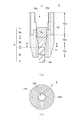
- FIG. 1A and 1B are diagrams showing the structure of a seed crystal holder for pulling a single crystal according to a first embodiment of the present invention, wherein FIG. 1A is a vertical sectional view, and FIG. It is a horizontal sectional view along line '.
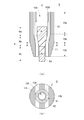
- 2A and 2B are diagrams showing the structure of a seed crystal holder for pulling a single crystal according to a second embodiment of the present invention, in which FIG. 2A is a vertical sectional view, and FIG. It is a horizontal sectional view along line '.
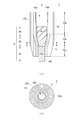
- 3A and 3B are diagrams showing the structure of a seed crystal holder for pulling a single crystal according to a third embodiment of the present invention, wherein FIG. 3A is a vertical sectional view, and FIG.
- FIG. 4A and 4B are diagrams showing the structure of a single crystal pulling seed crystal holder according to a fourth embodiment of the present invention, in which FIG. 4A is a vertical sectional view and FIG. It is a horizontal sectional view along line '.
- 5A and 5B are diagrams showing the structure of a seed crystal holder for pulling a single crystal according to a fifth embodiment of the present invention, wherein FIG. 5A is a vertical cross-sectional view, and FIG. 5B is an AA view of FIG. It is a horizontal sectional view along line '.
- 6A and 6B are diagrams showing the structure of a seed crystal holder for pulling a single crystal according to a sixth embodiment of the present invention, where FIG.
- FIG. 6A is a vertical sectional view and FIG. It is a horizontal sectional view along line '.
- 7A and 7B are views showing the structure of a seed crystal holder for pulling a single crystal according to a seventh embodiment of the present invention, wherein FIG. 7A is a vertical sectional view, and FIG. It is a horizontal sectional view along line '.
- FIG. 8 is a cross-sectional view showing an example of the structure of the silicon single crystal pulling apparatus.
- FIG. 9 is a schematic horizontal sectional view showing the structure of a conventional single crystal pulling seed crystal holder.
- FIG. 1 is a diagram showing the structure of a single crystal pulling seed crystal holder according to a first embodiment of the present invention, where (a) is a vertical sectional view and (b) is an AA view of (a). It is a horizontal sectional view along line '.
- the seed crystal holder 1 is a substantially cylindrical member made of a carbon fiber reinforced carbon composite material (also referred to as C / C composite). It is held by being inserted into the hollow portion 10h. The lower end portion 9d of the seed crystal 9 held by the seed crystal holder 1 protrudes downward from the lower end of the seed crystal holder 1, and the lower end portion 9d is pulled up while being immersed in the silicon melt to thereby form a silicon single piece. Crystals are grown. In addition, the up-down direction of the seed crystal holder 1 is determined based on a normal use state.
- Seed crystal 9 is an elongated rod-shaped (substantially columnar shape), and an upper 9a having a relatively large diameter R 1, and the tapered portion 9b having a diameter gradually reduced in diameter, a relatively small diameter R 2 (R 2 ⁇ And a lower portion 9c having R 1 ).
- the diameter of the upper part 9a and the lower part 9c is constant.
- the lower portion 9 c of the seed crystal 9 has a sufficient length that can protrude from the lower end of the seed crystal holder 1. Further, by using the seed crystal 9 that is as thick as possible, for example, a large-diameter and heavy silicon single crystal for a 450 mm wafer can be safely pulled up. When pulling up a heavy silicon single crystal, the effect of the present invention is also remarkable because the effect of stress concentration on the seed crystal 9 from the seed crystal holder 1 is large.
- Seed crystal holder 1 has a cylindrical upper 10a having a larger diameter than the diameter R 1 of the top 9a of the seed crystal 9, a cylindrical intermediate portion 10b which diameter is gradually reduced in diameter, the diameter R of the top 9a of the seed crystal 9 and a cylindrical lower 10c having a larger diameter than the diameter R 2 of the small and lower 9c than 1.
- the hollow portion 10 h of the seed crystal holder 1 has a shape that matches the outer shape of the seed crystal 9, extends in the vertical direction, and penetrates the seed crystal holder 1.
- a thread groove 10d is formed on the inner peripheral surface of the upper end portion of the cylindrical upper portion 10a so that the tip end portion of the pulling shaft of the silicon single crystal pulling apparatus can be screwed.
- the inner peripheral surface of the cylindrical intermediate portion 10 b is a tapered surface that matches the inclination angle of the tapered portion 9 b of the seed crystal 9.
- the taper surface on the inner periphery of the cylindrical intermediate portion 10b is more preferably a curved surface slightly bulging inward. In this way, by gently curving the inner peripheral surface of the cylindrical intermediate portion 10b, the cylindrical intermediate portion 10b can be reliably brought into contact with and supported by the tapered portion 9b of the seed crystal 9.
- the seed crystal holder 1 is made of a carbon fiber reinforced carbon composite material.
- the carbon fiber reinforced composite material is obtained by carbonizing (graphitizing) a matrix in which carbon fiber is impregnated with resin or pitch, and can improve mechanical strength while maintaining the characteristics of graphite.
- the carbon fibers 10f of the seed crystal holder 1 are oriented in the circumferential direction in a horizontal cross section orthogonal to the central axis Z, and are isotropic when viewed from the central axis Z. ing.
- the outer peripheral surface (tapered surface) of the seed crystal 9 in contact with the inner peripheral surface of the hollow portion 10h of the seed crystal holder Among them, the stress concentration on the surfaces (B portion and D portion) perpendicular to the fiber direction becomes larger than the surfaces parallel to the carbon fiber direction (A portion and C portion), and the seed crystal 9 may be broken. there were.
- the seed crystal holder 1 can be formed by a filament winding method (FW method) or a sheet winding method (SW method).
- a filament winding method a mold (mandrel) having the same shape as the hollow portion 10h is prepared, and an array of a plurality of carbon fibers impregnated with resin or pitch is wound around the mold to obtain a molded body.
- a carbon fiber cloth impregnated with resin or pitch is wound around a mold to obtain a molded body.
- the molded body is heated and carbonized (graphitized) in an inert gas atmosphere at a high temperature. The immersion of the molded body in a resin or the like and the carbonization step may be repeated a plurality of times.
- the seed crystal holder 1 is completed by adjusting the shape of the carbonized molded body and performing a finishing process such as polishing.
- the filament winding method it is preferable to wind the carbon fiber so that the winding angle of the carbon fiber relative to the core axis is as small as possible.
- the fiber component in the longitudinal direction can be increased and the tensile strength in the axial direction can be increased.
- the sheet winding method it is preferable to increase the tensile strength in the axial direction by using a carbon fiber cloth containing a longitudinal fiber component.
- the seed crystal holder 1 is a cylindrical member having a hollow portion formed of a carbon fiber reinforced carbon composite material, and the carbon fiber 10f has a horizontal cross section orthogonal to the central axis. Since the direction is the circumferential direction and isotropic, stress concentration on the seed crystal 9 of the seed crystal holder 1 can be prevented. Therefore, the seed crystal 9 can be prevented from being broken.
- FIG. 2A and 2B are diagrams showing the structure of a seed crystal holder for pulling a single crystal according to a second embodiment of the present invention, in which FIG. 2A is a vertical sectional view, and FIG. It is a horizontal sectional view along line '.
- the seed crystal holder 2 is characterized in that it is configured using a carbon fiber cloth including a fiber component parallel to the central axis Z. That is, the carbon fiber cloth, the fiber component 10f 1 circumferential direction intersecting the axial direction, and has both a direction parallel to the axial fiber component 10f 2.
- Other configurations are the same as those of the first embodiment.
- the orientation of the fiber component contained in the carbon fiber cloth is parallel to the axial direction in the sheet winding method in which a carbon fiber cloth impregnated with resin or the like is wound around a mold to obtain a molded body. It can shape
- the carbon fiber cloth since the carbon fiber cloth includes the fiber component 10f 1 in the circumferential direction intersecting the axial direction, stress concentration on the seed crystal 9 of the seed crystal holder 1 is prevented as in the first embodiment. can do.
- the carbon fiber cloth comprises axially parallel fiber component 10f 2, it is possible to enhance the axial tensile strength of the seed crystal holder 2.
- FIG. 3A and 3B are diagrams showing the structure of a seed crystal holder for pulling a single crystal according to a third embodiment of the present invention, wherein FIG. 3A is a vertical sectional view, and FIG. It is a horizontal sectional view along line '.
- the seed crystal holder 3 is characterized in that only the portion of the seed crystal 9 that contacts the outer peripheral surface of the tapered portion 9b has an isotropic fiber structure.
- the other part is that it has an anisotropic fiber structure.
- the seed crystal holder 3 according to the present embodiment includes a combination of a core part 11 having an isotropic fiber structure and a clad part 12 having an anisotropic fiber structure.
- the core part 11 is mainly a cylinder. It is provided in the inner peripheral side region of the intermediate portion 10b.
- the carbon fibers 11 f of the core portion 11 are oriented in the circumferential direction in a horizontal section orthogonal to the central axis Z, and are isotropic when viewed from the central axis Z.
- the carbon fibers 12f of the cladding portion 12 are oriented in one direction straight in the horizontal cross section and have anisotropy when viewed from the central axis Z.
- Other configurations are the same as those of the first embodiment.
- the core portion 11 only needs to be provided at least in the inner peripheral region of the cylindrical intermediate portion 10b in contact with the seed crystal 9, and does not prevent the core portion 11 from reaching the cylindrical upper portion 10a and the cylindrical lower portion 10c. Therefore, for example, as shown in the drawing, a part of the core portion 11 may extend to the cylindrical upper portion 10a and the cylindrical lower portion 10c. The core portion 11 may extend over the entire radial direction from the inner peripheral side region to the outer peripheral side region of the cylindrical intermediate portion 10b.
- the core portion 11 is formed integrally with the clad portion 12.
- the clad portion 12 is made of a carbon fiber cloth, and a planar carbon fiber cloth is multilayered.
- the plane of the carbon fiber cloth is parallel to the central axis Z and is oriented in a specific direction in the horizontal section.
- the carbon fiber cloth preferably has not only a fiber component intersecting with the central axis Z but also a fiber component parallel to the central axis Z. According to this, the tensile strength of the axial direction of the whole holder can be strengthened.
- the thread groove 10d for screwing the lifting shaft is provided on the clad portion 12 side.
- the strength of the thread groove 10d can be further increased.
- the core portion 11 can be formed by a filament winding method (FW method) or a sheet winding method (SW method).
- the clad part 12 can be shape
- a carbon fiber cloth molded using a mold is impregnated with resin and the like, and defoamed using a brush or roller, and the carbon fiber cloth is laminated to a predetermined thickness to form a molded body. obtain.
- the seed crystal holder 3 is completed by adjusting the shape of the carbonized molded body and performing a finishing process such as polishing.
- the seed crystal holder 3 Since the seed crystal holder 3 according to the present embodiment has an isotropic fiber structure in a portion in contact with the seed crystal 9, stress concentration on the seed crystal 9 of the seed crystal holder 1 can be prevented. The seed crystal 9 can be prevented from being broken. Moreover, since the fiber structure of the cladding part 12 has anisotropy and has a fiber component parallel to the central axis Z, the tensile strength in the axial direction can be increased, and the mechanical strength of the seed crystal holder is improved. be able to.
- FIG. 4A and 4B are diagrams showing the structure of a single crystal pulling seed crystal holder according to a fourth embodiment of the present invention, in which FIG. 4A is a vertical sectional view and FIG. It is a horizontal sectional view along line '.
- the seed crystal holder 4 is characterized in that the lower half is made up of the core part 11 and the upper half is made up of the clad part 12. That is, the core part 11 is mainly provided in the cylindrical intermediate part 10b and the cylindrical lower part 10c, and the clad part 12 is provided in the cylindrical upper part 10a. A part of the core portion 11 extends to the cylindrical upper portion 10a, and the vertical boundary surface between the core portion 11 and the cladding portion 12 is an uneven surface, so that the vertical direction between the core portion 11 and the cladding portion 12 is vertical. The connection strength can be increased. Other configurations are the same as those of the third embodiment.
- the seed crystal holder 4 also has an isotropic fiber structure of the core portion 11 constituting the contact surface with the seed crystal 9, the stress on the seed crystal 9 of the seed crystal holder 1. Concentration can be prevented, and breakage of the seed crystal 9 can be prevented.
- the fiber structure of the cladding part 12 has anisotropy and has a fiber component parallel to the central axis Z, the tensile strength in the axial direction can be increased, and the mechanical strength of the seed crystal holder is improved. be able to.
- the core part 11 and the clad part 12 can be formed separately and then integrated by carbonization, or the core part 11 and the clad part can be integrated using pins or bolts. 12 can be mechanically connected to each other, so that the manufacturing is easy, the manufacturing cost can be reduced, and the processing accuracy can be improved.
- FIG. 5A and 5B are diagrams showing the structure of a seed crystal holder for pulling a single crystal according to a fifth embodiment of the present invention, wherein FIG. 5A is a vertical cross-sectional view, and FIG. 5B is an AA view of FIG. It is a horizontal sectional view along line '.
- the seed crystal holder 5 is characterized in that the entire inner peripheral region of the cylindrical upper part 10a, the cylindrical intermediate part 10b, and the cylindrical lower part 10c is composed of the core part 11, The entire outer peripheral region is formed by the clad portion 12. Since the entire inner peripheral surface of the hollow portion 10h of the seed crystal holder 5 is composed of the core portion 11, a thread groove 10d for screwing the lifting shaft is provided on the core portion 11 side. Other configurations are the same as those of the third embodiment.
- the seed crystal holder 5 according to the present embodiment also has an isotropic fiber structure of the core portion 11 constituting the contact surface with the seed crystal 9, the stress on the seed crystal 9 of the seed crystal holder 1 is the same. Concentration can be prevented, and breakage of the seed crystal 9 can be prevented. Moreover, since the fiber structure of the cladding part 12 has anisotropy and has a fiber component parallel to the central axis Z, the tensile strength in the axial direction can be increased, and the mechanical strength of the seed crystal holder is improved. be able to. Furthermore, the seed crystal holder 5 according to the present embodiment is easier to process than the seed crystal holder 3 according to the third embodiment, and the manufacturing cost can be reduced and the processing accuracy can be improved.
- FIG. 6A and 6B are diagrams showing the structure of a seed crystal holder for pulling a single crystal according to a sixth embodiment of the present invention, where FIG. 6A is a vertical sectional view and FIG. It is a horizontal sectional view along line '.
- the seed crystal holder 6 is characterized in that the core portion 11 and the clad portion 12 are formed of separate members, and the core portion is formed inside the cylindrical clad portion 12. 11 has a socket structure in which 11 is accommodated.
- the third feature is that the core portion 11 in contact with the outer peripheral surface of the tapered portion 9b of the seed crystal 9 has an isotropic fiber structure, and the outer cladding portion 12 of the core portion 11 has an anisotropic fiber structure. This is the same as the embodiment.
- the core part 11 is detachable from the clad part 12.
- a taper surface is provided on the outer peripheral surface of the core part 11, and the core part 11 is fixed in the clad part 12 by the surface contact with the tapered inner peripheral surface of the clad part 12.
- the core part 11 may be set on the clad part 12 with the seed crystal 9 set in advance, or the seed crystal 9 may be set after the core part 11 is set on the clad part 12.
- the core portion 11 and the clad portion 12 can be separately manufactured, so that the manufacturing is very easy. Moreover, since the core part 11 and the clad part 12 can each be replaced
- FIG. 7A and 7B are views showing the structure of a seed crystal holder for pulling a single crystal according to a seventh embodiment of the present invention, wherein FIG. 7A is a vertical sectional view, and FIG. It is a horizontal sectional view along line '.
- the seed crystal holder 7 is characterized in that the entire inner peripheral region of the cylindrical upper part 10a, the cylindrical intermediate part 10b, and the cylindrical lower part 10c is composed of the core part 11,
- the outer peripheral side region is made of a clad portion 12
- the core portion 11 has an isotropic fiber structure formed by a filament winding method
- the clad portion 12 is formed by a sheet winding method (SW method). It has a fiber structure.
- the cladding portion 12 are used carbon fiber cloth, carbon fiber cloth has a fiber component 12f 1 circumferential direction intersecting the axial direction, both the direction parallel to the axial fiber component 12f 2. Since the entire inner peripheral surface of the hollow portion 10 h of the seed crystal holder 5 is formed by the core portion 11, a screw groove 10 d for screwing the pulling shaft is provided on the core portion 11 side.
- the seed crystal holder 7 can be formed by combining the filament winding method (FW method) and the sheet winding method (SW method). That is, first, the molded body of the core part 11 is formed by the filament winding method, and the cladding part 12 is formed by winding a carbon fiber cloth impregnated with a resin or the like around the molded body of the core part 11. In this case, it is necessary to the orientation direction of the fiber components 12f 2 included in the carbon fiber cloth is wound carbon fiber cloth in parallel with the axial direction. Next, the molded body is heated and carbonized (graphitized) in an inert gas atmosphere at a high temperature. Thereafter, the seed crystal holder 7 is completed by adjusting the shape of the carbonized molded body and performing a finishing process such as polishing.
- FW method filament winding method
- SW method sheet winding method
- the seed crystal holder 7 according to the present embodiment has isotropicity not only in the fiber structure of the core part 11 constituting the contact surface with the seed crystal 9 but also in the fiber structure of the clad part 12. Stress concentration on the seed crystal 9 of the crystal holder 1 can be prevented, and breakage of the seed crystal 9 can be prevented. Further, since the carbon fiber cloth which constitutes the cladding portion 12 has a central axis Z parallel to the fiber component 12f 2, it is possible to enhance the axial tensile strength, to improve the mechanical strength of the seed crystal holder it can. Furthermore, the seed crystal holder 7 according to the present embodiment is easier to process than the seed crystal holder 5 according to the fifth embodiment, and the manufacturing cost can be reduced and the processing accuracy can be improved.
- FIG. 8 is a cross-sectional view showing an example of the structure of a silicon single crystal pulling apparatus.
- the silicon single crystal pulling apparatus 20 supports a chamber 21, a heat insulating material 22 disposed inside the chamber 21, a quartz crucible 23 installed in the chamber 21, and the quartz crucible 23.
- the wire 28 extends straight down from the wire winding mechanism 29 disposed above the chamber 21 and reaches the vicinity of the quartz crucible 23.
- a seed crystal holder 30 is attached to the tip of the wire 28, and the seed crystal holder 30 holds the seed crystal.
- the seed crystal holder 30 any of the seed crystal holders 1 to 7 according to the first to seventh embodiments can be used.
- a quartz crucible 23 is set in the susceptor 24, a polycrystalline silicon raw material is filled in the quartz crucible 23, and a seed crystal is set in the seed crystal holder 30.
- the silicon raw material is heated by the heater 26 to generate the silicon melt 31, and the seed crystal is lowered to be deposited on the silicon melt 31.
- the seed crystal is slowly raised while rotating the seed crystal and the quartz crucible 23 to grow a substantially cylindrical silicon single crystal 32.
- FIG. 1 shows a state in which a silicon single crystal 32 that is being grown is suspended from a wire 28 via a seed crystal holder 30.
- the diameter of the silicon single crystal 32 is controlled by controlling the pulling speed and the power of the heater 26.
- the shoulder portion is formed by gradually widening the crystal diameter. For example, when a specified diameter of 450 mm or more is reached, the pulling condition is changed to form a body portion having a constant diameter. Furthermore, at the end of the pulling up, the diameter is narrowed down to form a tail portion, and finally cut off from the liquid surface. Thus, a silicon single crystal ingot is completed.
- the seed crystal holder according to the present invention is not limited to pulling a silicon single crystal, and can be used for pulling various single crystals. it can.
- the angle of the taper surface of the hollow part 10h of a seed crystal holder is made the same angle as the taper surface of the seed crystal 9, it may be made larger than the angle of the taper surface of the seed crystal 9. Is possible.
- the above embodiments can be arbitrarily combined as necessary.
Landscapes
- Chemical & Material Sciences (AREA)
- Engineering & Computer Science (AREA)
- Organic Chemistry (AREA)
- Materials Engineering (AREA)
- Ceramic Engineering (AREA)
- Metallurgy (AREA)
- Crystallography & Structural Chemistry (AREA)
- Composite Materials (AREA)
- Chemical Kinetics & Catalysis (AREA)
- Manufacturing & Machinery (AREA)
- Structural Engineering (AREA)
- Crystals, And After-Treatments Of Crystals (AREA)
- Ceramic Products (AREA)
Abstract
Description
8f 炭素繊維
9 種結晶
9a 種結晶の上部
9b 種結晶のテーパー部
9c 種結晶の下部
9d 種結晶の下端部
10a 円筒上部
10b 円筒中間部
10c 円筒下部
10d ねじ溝
10f 炭素繊維
10f1 炭素繊維の周方向の繊維成分
10f2 炭素繊維の軸方向と平行な繊維成分
10h 中空部
11 コア部
11f 炭素繊維
12 クラッド部
12f 炭素繊維
12f1 炭素繊維の周方向の繊維成分
12f2 炭素繊維の軸方向と平行な繊維成分
20 シリコン単結晶引き上げ装置
21 チャンバー
22 断熱材
23 石英ルツボ
24 サセプタ
25 回転支持軸
26 ヒーター
27 熱遮蔽体
28 単結晶引き上げ用ワイヤー
29 ワイヤー巻き取り機構
30 種結晶保持具
31 シリコン融液
32 シリコン単結晶
Claims (15)
- 炭素繊維強化炭素複合材料からなり、略棒状の種結晶の外形に合致する形状の中空部を有する略円筒状の単結晶引き上げ用種結晶保持具であって、
少なくとも種結晶の外周面と接触する部分の炭素繊維の方向が前記中空部の中心軸から見て等方性を有することを特徴とする種結晶保持具。 - 前記種結晶の外周面と接触する部分の前記炭素繊維の方向が周方向成分を有する、請求項1に記載の種結晶保持具。
- 前記種結晶の外周面と接触する部分の前記炭素繊維の方向が前記中心軸と平行な成分をさらに有する、請求項2に記載の種結晶保持具。
- 前記種結晶は、直径が徐々に小さくなるテーパー部を有し、
前記中空部は、前記テーパー部に面接触する内周面を有し、
前記内周面を構成する部分の前記炭素繊維の方向が前記中空部の中心軸から見て等方性を有する、請求項1乃至3のいずれか一項に記載の種結晶保持具。 - 種結晶保持具全体の前記炭素繊維の方向が前記中空部の中心軸から見て等方性を有する、請求項1乃至4のいずれか一項に記載の種結晶保持具。
- 前記種結晶の外周面と接触する部分以外の部分の炭素繊維の方向が前記中空部の中心軸から見て異方性を有する、請求項1乃至4のいずれか一項に記載の種結晶保持具。
- 炭素繊維強化炭素複合材料からなり、略棒状の種結晶の外形に合致する形状の中空部を有する略円筒状の単結晶引き上げ用種結晶保持具であって、
炭素繊維の方向が前記中空部の中心軸から見て等方性を有するコア部と、
炭素繊維の方向が前記中空部の中心軸から見て異方性を有するクラッド部とを有し、
前記コア部は、少なくとも前記種結晶の外周面と接触する部分に設けられていることを特徴とする種結晶保持具。 - 前記コア部の炭素繊維の方向が周方向成分を有する、請求項7に記載の種結晶保持具。
- 前記コア部の炭素繊維の方向が前記中心軸と平行な成分を有する、請求項8に記載の種結晶保持具。
- 第1の口径を有する円筒上部と、
前記円筒上部の下方に位置し、前記第1の口径から第2の口径まで徐々に縮径した円筒中間部と、
前記円筒中間部の下方に位置し、前記第2の口径を有する円筒下部とを有し、
前記コア部は、少なくとも前記円筒中間部の内周側領域に設けられており、
前記クラッド部は、前記コア部の形成領域以外の領域に設けられている、請求項7乃至9のいずれか一項に記載の種結晶保持具。 - 前記コア部は、前記円筒中間部及び前記円筒下部に設けられており、
前記クラッド部は、前記円筒上部に設けられている、請求項10に記載の種結晶保持具。 - 前記コア部は、前記円筒上部、前記円筒中間部及び前記円筒下部の前記内周側領域に設けられており、
前記クラッド部は、前記円筒上部、前記円筒中間部及び前記円筒下部の外周側領域に設けられている、請求項10に記載の種結晶保持具。 - 前記コア部は前記クラッド部に対して着脱自在に設けられている請求項7乃至9のいずれか一項に記載の種結晶保持具。
- 炭素繊維強化炭素複合材料からなり、略棒状の種結晶の外形に合致する形状の中空部を有する略円筒状の単結晶引き上げ用種結晶保持具であって、
炭素繊維の方向が前記中空部の中心軸から見て等方性を有するコア部と、
炭素繊維の方向が前記中空部の中心軸から見て等方性を有するクラッド部とを有し、
前記コア部の炭素繊維の方向は周方向成分を有し、
前記クラッド部の炭素繊維の方向は周方向成分と前記中心軸と平行な成分の両方を有し、
前記コア部は、少なくとも前記種結晶の外周面と接触する部分に設けられており、
前記クラッド部は、前記コア部の形成領域以外の領域に設けられていることを特徴とする種結晶保持具。 - 請求項1乃至14のいずれか一項に記載の種結晶保持具を用いて直径450mm以上のシリコン単結晶をCZ法により引き上げることを特徴とするシリコン単結晶の製造方法。
Priority Applications (5)
| Application Number | Priority Date | Filing Date | Title |
|---|---|---|---|
| CN201680020784.1A CN107429422B (zh) | 2015-04-09 | 2016-02-18 | 单晶提拉用晶种保持器及使用该装置的硅单晶的制造方法 |
| US15/564,080 US10385473B2 (en) | 2015-04-09 | 2016-02-18 | Seed crystal holder for pulling up single crystal and method of manufacturing silicon single crystal using the same |
| KR1020177030409A KR101988655B1 (ko) | 2015-04-09 | 2016-02-18 | 단결정 인상용 시드 결정 유지구 및 이를 이용한 실리콘 단결정의 제조 방법 |
| US16/502,383 US10822717B2 (en) | 2015-04-09 | 2019-07-03 | Seed crystal holder for pulling up single crystal and method of manufacturing silicon single crystal using the same |
| US17/039,060 US11371160B2 (en) | 2015-04-09 | 2020-09-30 | Seed crystal holder for pulling up single crystal and method of manufacturing silicon single crystal using the same |
Applications Claiming Priority (2)
| Application Number | Priority Date | Filing Date | Title |
|---|---|---|---|
| JP2015-079864 | 2015-04-09 | ||
| JP2015079864A JP6592941B2 (ja) | 2015-04-09 | 2015-04-09 | 単結晶引き上げ用種結晶保持具及びこれを用いたシリコン単結晶の製造方法 |
Related Child Applications (2)
| Application Number | Title | Priority Date | Filing Date |
|---|---|---|---|
| US15/564,080 A-371-Of-International US10385473B2 (en) | 2015-04-09 | 2016-02-18 | Seed crystal holder for pulling up single crystal and method of manufacturing silicon single crystal using the same |
| US16/502,383 Division US10822717B2 (en) | 2015-04-09 | 2019-07-03 | Seed crystal holder for pulling up single crystal and method of manufacturing silicon single crystal using the same |
Publications (1)
| Publication Number | Publication Date |
|---|---|
| WO2016163161A1 true WO2016163161A1 (ja) | 2016-10-13 |
Family
ID=57072606
Family Applications (1)
| Application Number | Title | Priority Date | Filing Date |
|---|---|---|---|
| PCT/JP2016/054653 Ceased WO2016163161A1 (ja) | 2015-04-09 | 2016-02-18 | 単結晶引き上げ用種結晶保持具及びこれを用いたシリコン単結晶の製造方法 |
Country Status (5)
| Country | Link |
|---|---|
| US (3) | US10385473B2 (ja) |
| JP (1) | JP6592941B2 (ja) |
| KR (1) | KR101988655B1 (ja) |
| CN (2) | CN107429422B (ja) |
| WO (1) | WO2016163161A1 (ja) |
Cited By (2)
| Publication number | Priority date | Publication date | Assignee | Title |
|---|---|---|---|---|
| CN108203842A (zh) * | 2016-12-20 | 2018-06-26 | 深圳市晶格材料科技有限公司 | 一种晶体生长用易装配低成本籽晶夹头 |
| CN119041005A (zh) * | 2024-10-31 | 2024-11-29 | 北京晶格领域半导体有限公司 | 一种快速生长大尺寸高质量立方碳化硅单晶的装置及方法 |
Families Citing this family (2)
| Publication number | Priority date | Publication date | Assignee | Title |
|---|---|---|---|---|
| WO2021072239A1 (en) * | 2019-10-09 | 2021-04-15 | Gcl Solar Materials Us Iii, Llc | Method, system and apparatus for growing hollow core silicon single crystals |
| CN111826711A (zh) * | 2020-08-21 | 2020-10-27 | 陕西美兰德炭素有限责任公司 | 一种单晶炉用碳碳复合材料籽晶夹头 |
Citations (2)
| Publication number | Priority date | Publication date | Assignee | Title |
|---|---|---|---|---|
| JPH09295889A (ja) * | 1996-05-01 | 1997-11-18 | Toyo Tanso Kk | 半導体単結晶引き上げ装置のシードチャック |
| JPH09315883A (ja) * | 1996-05-31 | 1997-12-09 | Sumitomo Sitix Corp | 単結晶引き上げ用種結晶保持具 |
Family Cites Families (10)
| Publication number | Priority date | Publication date | Assignee | Title |
|---|---|---|---|---|
| JP2937113B2 (ja) * | 1996-03-15 | 1999-08-23 | 住友金属工業株式会社 | 種結晶保持具 |
| US6015461A (en) * | 1997-09-12 | 2000-01-18 | Sumitomo Sitix Corporation | Seed crystal holders, for pulling a single crystal |
| US6139632A (en) * | 1997-09-15 | 2000-10-31 | Sumitomo Sitix Corporation | Seed crystals, seed crystal holders, and a method for pulling a single crystal |
| JP3980136B2 (ja) | 1997-10-20 | 2007-09-26 | Sumco Techxiv株式会社 | 単結晶製造装置及び単結晶製造方法 |
| JP3402192B2 (ja) | 1998-04-15 | 2003-04-28 | 信越半導体株式会社 | シリコン単結晶の製造方法および種結晶ならびに種結晶保持具 |
| JP5239265B2 (ja) * | 2007-09-07 | 2013-07-17 | 株式会社Sumco | シリコン単結晶引上げ用種結晶及び該種結晶を使用したシリコン単結晶の製造方法 |
| KR20090046301A (ko) * | 2007-11-05 | 2009-05-11 | 삼성전기주식회사 | 단결정 기판 제조방법 및 이를 이용한 태양전지 제조방법 |
| JP2011010394A (ja) | 2009-06-23 | 2011-01-13 | Sanyo Electric Co Ltd | ドライバ回路 |
| CN102057083B (zh) * | 2009-07-21 | 2013-09-11 | 丰田自动车株式会社 | 使用熔液法的单晶生长用籽晶轴 |
| CN102492983A (zh) * | 2011-12-22 | 2012-06-13 | 浙江金瑞泓科技股份有限公司 | 用于直拉硅单晶生长的晶种夹头 |
-
2015
- 2015-04-09 JP JP2015079864A patent/JP6592941B2/ja active Active
-
2016
- 2016-02-18 CN CN201680020784.1A patent/CN107429422B/zh active Active
- 2016-02-18 KR KR1020177030409A patent/KR101988655B1/ko active Active
- 2016-02-18 CN CN201911030127.7A patent/CN110804760B/zh active Active
- 2016-02-18 US US15/564,080 patent/US10385473B2/en active Active
- 2016-02-18 WO PCT/JP2016/054653 patent/WO2016163161A1/ja not_active Ceased
-
2019
- 2019-07-03 US US16/502,383 patent/US10822717B2/en active Active
-
2020
- 2020-09-30 US US17/039,060 patent/US11371160B2/en active Active
Patent Citations (2)
| Publication number | Priority date | Publication date | Assignee | Title |
|---|---|---|---|---|
| JPH09295889A (ja) * | 1996-05-01 | 1997-11-18 | Toyo Tanso Kk | 半導体単結晶引き上げ装置のシードチャック |
| JPH09315883A (ja) * | 1996-05-31 | 1997-12-09 | Sumitomo Sitix Corp | 単結晶引き上げ用種結晶保持具 |
Cited By (2)
| Publication number | Priority date | Publication date | Assignee | Title |
|---|---|---|---|---|
| CN108203842A (zh) * | 2016-12-20 | 2018-06-26 | 深圳市晶格材料科技有限公司 | 一种晶体生长用易装配低成本籽晶夹头 |
| CN119041005A (zh) * | 2024-10-31 | 2024-11-29 | 北京晶格领域半导体有限公司 | 一种快速生长大尺寸高质量立方碳化硅单晶的装置及方法 |
Also Published As
| Publication number | Publication date |
|---|---|
| KR101988655B1 (ko) | 2019-06-12 |
| CN110804760A (zh) | 2020-02-18 |
| US10385473B2 (en) | 2019-08-20 |
| US20180135201A1 (en) | 2018-05-17 |
| US10822717B2 (en) | 2020-11-03 |
| US11371160B2 (en) | 2022-06-28 |
| CN107429422A (zh) | 2017-12-01 |
| US20210010156A1 (en) | 2021-01-14 |
| US20190323144A1 (en) | 2019-10-24 |
| JP6592941B2 (ja) | 2019-10-23 |
| JP2016199420A (ja) | 2016-12-01 |
| CN107429422B (zh) | 2019-10-29 |
| CN110804760B (zh) | 2021-08-03 |
| KR20170130521A (ko) | 2017-11-28 |
Similar Documents
| Publication | Publication Date | Title |
|---|---|---|
| US11371160B2 (en) | Seed crystal holder for pulling up single crystal and method of manufacturing silicon single crystal using the same | |
| KR101242366B1 (ko) | 도가니 보유 지지 부재 및 그 제조 방법 | |
| EP2206810B1 (en) | Crucible holding member and method for producing the same | |
| JP5286591B2 (ja) | ルツボ保持部材及びその製造方法 | |
| US20090211518A1 (en) | Crucible holding member and method for producing the same | |
| EP2098618B1 (en) | Container holding member and method for producing the same | |
| JP2012254916A (ja) | 炭素繊維強化炭素複合円筒部材及び炭素繊維強化炭素複合円筒部材の製造方法、並びに炭素繊維強化炭素複合材ルツボ及びこのルツボの製造方法 | |
| JP3198914B2 (ja) | 単結晶引き上げ用黒鉛ルツボ及びその製造方法 | |
| JPH11255587A (ja) | 単結晶引き上げ用炭素繊維強化炭素材るつぼおよびその製造方法 | |
| JPH09315883A (ja) | 単結晶引き上げ用種結晶保持具 | |
| JP3734004B2 (ja) | シリコン単結晶引上げ用黒鉛ルツボ | |
| JPH09315884A (ja) | 単結晶引き上げ用種結晶保持具及び種結晶 | |
| JP2012076956A (ja) | 炭素ルツボ及びこの炭素ルツボを用いたシリコン単結晶の製造方法 | |
| JP4529158B2 (ja) | 単結晶引き上げ用ルツボ |
Legal Events
| Date | Code | Title | Description |
|---|---|---|---|
| 121 | Ep: the epo has been informed by wipo that ep was designated in this application |
Ref document number: 16776330 Country of ref document: EP Kind code of ref document: A1 |
|
| WWE | Wipo information: entry into national phase |
Ref document number: 15564080 Country of ref document: US |
|
| NENP | Non-entry into the national phase |
Ref country code: DE |
|
| ENP | Entry into the national phase |
Ref document number: 20177030409 Country of ref document: KR Kind code of ref document: A |
|
| 122 | Ep: pct application non-entry in european phase |
Ref document number: 16776330 Country of ref document: EP Kind code of ref document: A1 |