WO2016162972A1 - 映像表示装置および映像表示方法 - Google Patents
映像表示装置および映像表示方法 Download PDFInfo
- Publication number
- WO2016162972A1 WO2016162972A1 PCT/JP2015/060965 JP2015060965W WO2016162972A1 WO 2016162972 A1 WO2016162972 A1 WO 2016162972A1 JP 2015060965 W JP2015060965 W JP 2015060965W WO 2016162972 A1 WO2016162972 A1 WO 2016162972A1
- Authority
- WO
- WIPO (PCT)
- Prior art keywords
- adjustment
- video
- color
- saturation
- correction
- Prior art date
- Legal status (The legal status is an assumption and is not a legal conclusion. Google has not performed a legal analysis and makes no representation as to the accuracy of the status listed.)
- Ceased
Links
Images










Classifications
-
- H—ELECTRICITY
- H04—ELECTRIC COMMUNICATION TECHNIQUE
- H04N—PICTORIAL COMMUNICATION, e.g. TELEVISION
- H04N9/00—Details of colour television systems
- H04N9/64—Circuits for processing colour signals
- H04N9/68—Circuits for processing colour signals for controlling the amplitude of colour signals, e.g. automatic chroma control circuits
-
- G—PHYSICS
- G06—COMPUTING OR CALCULATING; COUNTING
- G06T—IMAGE DATA PROCESSING OR GENERATION, IN GENERAL
- G06T1/00—General purpose image data processing
-
- H—ELECTRICITY
- H04—ELECTRIC COMMUNICATION TECHNIQUE
- H04N—PICTORIAL COMMUNICATION, e.g. TELEVISION
- H04N1/00—Scanning, transmission or reproduction of documents or the like, e.g. facsimile transmission; Details thereof
- H04N1/46—Colour picture communication systems
-
- H—ELECTRICITY
- H04—ELECTRIC COMMUNICATION TECHNIQUE
- H04N—PICTORIAL COMMUNICATION, e.g. TELEVISION
- H04N1/00—Scanning, transmission or reproduction of documents or the like, e.g. facsimile transmission; Details thereof
- H04N1/46—Colour picture communication systems
- H04N1/56—Processing of colour picture signals
- H04N1/60—Colour correction or control
Definitions
- the present invention relates to a video display device and a video display method in the video display device.
- an LED is used as a light source, so that a wider range of colors can be expressed than when a conventional fluorescent tube is used. Therefore, when the same video signal is displayed on different display devices, it may be displayed with different image quality, and it is desired to display the image as close as possible by image quality adjustment.
- the performance of the display device needs to be corrected while making use of it as much as possible, and the image quality preference varies from individual to individual, so the user can adjust the image quality for each display device as well as the user's preference.
- An image quality adjustment function is required.
- a technology that is realized by performing video correction in a display device has been developed.
- Patent Document 1 discloses a technique in which a video signal is divided into luminance, hue, and saturation elements, and a specific color correction is performed by designating a predetermined range of each element.
- the user specifies a desired color and can correct the specified color according to his / her preference.
- the correction amount according to the saturation is not considered.
- the designated color area includes an area that is light in color and close to white, the area may be colored.
- An object of the present invention is to provide a video display technique that minimizes side effects caused by color correction.
- the video display device in one embodiment is a video display device capable of color adjustment processing of input video.
- the video display device includes a video input unit, a color adjustment unit that performs color adjustment processing of a video input to the video input unit, and a display unit that displays the video color-adjusted by the color adjustment unit.
- the color adjustment unit divides a color space about three axes of luminance or brightness, saturation, and hue into a plurality of regions, and the luminance for each region of the plurality of regions Adjustment or brightness adjustment, saturation adjustment, and hue adjustment can be performed, respectively.
- one area of the plurality of areas includes a first position where saturation before correction is a first value, and a second position where saturation before correction is higher than the first value. And the influence of the brightness adjustment, the brightness adjustment, the saturation adjustment, and the hue adjustment is smaller in the first position than in the second position.
- the video display method in one embodiment is a video display method in a video display device capable of color adjustment processing of an input video.
- the video display method includes a video input step, a color adjustment step for performing color adjustment processing of the video input in the video input step, and a display step for displaying the video color-adjusted in the color adjustment step.
- a color adjustment step in the color adjustment process for the video, a color space having three axes of luminance or brightness, saturation, and hue as axes is divided into a plurality of regions, and the luminance of each region of the plurality of regions is determined. Adjustment or brightness adjustment, saturation adjustment, and hue adjustment can be performed, respectively.
- one area of the plurality of areas includes a first position where saturation before correction is a first value, and a second position where saturation before correction is higher than the first value. And the influence of the brightness adjustment, the brightness adjustment, the saturation adjustment, and the hue adjustment is smaller in the first position than in the second position.
- Embodiment 1 of this invention It is a figure which shows an example of a structure of the video display apparatus in Embodiment 1 of this invention. It is a figure which shows an example of a structure of the video correction
- Embodiment 1 of this invention it is a figure which shows an example of the input-output characteristic of an image
- Embodiment 1 of this invention it is a figure which shows an example of the input / output characteristic of another image
- Embodiment 2 of this invention it is a figure which shows an example of the color space of an image
- Embodiment 2 of this invention it is a figure which shows an example of the correction
- Embodiment 2 of this invention it is a figure which shows an example of the input / output characteristic of an image
- Embodiment 3 of this invention it is a figure which shows an example of the color space of an image
- Embodiment 3 of this invention it is a figure which shows an example of the hue correction characteristic of an image
- the constituent elements are not necessarily indispensable unless otherwise specified and apparently indispensable in principle. Needless to say.
- the shape and positional relationship of components and the like when referring to the shape and positional relationship of components and the like, the shape is substantially the same unless otherwise specified and the case where it is not clearly apparent in principle. And the like are included. The same applies to the above numerical values and ranges. [Outline of the embodiment]
- the video display device in one embodiment is a video display device capable of color adjustment processing of input video.
- the video display device includes a video input unit (input signal processing unit 11), a color adjustment unit (video correction unit 100) that performs color adjustment processing of video input to the video input unit, and a color adjustment unit that performs color adjustment. And a display unit (optical system device 200) for displaying the adjusted video.
- the color adjustment unit divides a color space about three axes of luminance or brightness, saturation, and hue into a plurality of regions, and the luminance for each region of the plurality of regions Adjustment or brightness adjustment, saturation adjustment, and hue adjustment can be performed, respectively.
- one area of the plurality of areas includes a first position where saturation before correction is a first value, and a second position where saturation before correction is higher than the first value. And the influence of the brightness adjustment, the brightness adjustment, the saturation adjustment, and the hue adjustment is smaller in the first position than in the second position.
- the video display method in one embodiment is a video display method in a video display device capable of color adjustment processing of an input video.
- the video display method includes a video input step (operation in the input signal processing unit 11), a color adjustment step for performing color adjustment processing of the video input in the video input step (operation in the video correction unit 100), and the color And a display step (operation in the optical system apparatus 200) for displaying the image color-adjusted in the adjustment step.
- a color space having three axes of luminance or brightness, saturation, and hue as axes is divided into a plurality of regions, and the luminance of each region of the plurality of regions is determined.
- Adjustment or brightness adjustment, saturation adjustment, and hue adjustment can be performed, respectively.
- one area of the plurality of areas includes a first position where saturation before correction is a first value, and a second position where saturation before correction is higher than the first value. And the influence of the brightness adjustment, the brightness adjustment, the saturation adjustment, and the hue adjustment is smaller in the first position than in the second position.
- a video display device having a color correction function will be described using a projector configuration.
- the color correction function includes a color adjustment function for performing color adjustment processing of the input video.
- a front projector will be described, but the form may be a rear projection television.
- a display device using a direct-view flat display such as a liquid crystal display, a plasma display, or an organic EL display may be used. This is the same in any of the following embodiments.
- FIG. 1 is a diagram illustrating an example of a configuration of a video display device according to the present embodiment.
- the video display device includes an input signal processing unit 11, a video correction unit 100, a timing control unit 14, and an optical system device 200.
- the input signal processing unit 11 is means for receiving the input video signal 10 and performing a predetermined process according to the video format to convert it into an RGB internal video signal 12.
- the video correction unit 100 is a unit that receives the internal video signal 12 and the control signal 25, corrects the internal video signal 12 based on the control signal 25, and outputs a corrected video signal 13.
- the timing control unit 14 is a means for receiving the corrected video signal 13 and generating the display control signal 15 by controlling the corrected video signal 13 based on the horizontal / vertical synchronization signal of the display screen.
- the optical system device 200 is a device that displays an image, and includes a light source 203, a panel 202, and a lens 201.
- the light source 203 is a means for irradiating light for projecting an image on a screen.
- the panel 202 is a unit that receives the display control signal 15 and adjusts the gradation of the light beam from the light source 203 for each pixel to create a projected image.
- the lens 201 is a means for enlarging and projecting the projection image from the panel 202 onto the screen.
- the lens 201 of the optical system device 200 is not necessary. The user looks directly at the panel 202.
- the correction characteristics of the processing of the video correction unit 100 are controlled by the control signal 25.
- the control signal 25 is a control signal for correcting an image based on, for example, a user's button operation on a remote controller or a display device.
- the video display device in this embodiment includes a remote controller, a display device, and the like.
- the input signal processing unit 11 receives the input video signal 10 and performs processing such as IP conversion and scaler according to the video format to obtain the RGB format.
- the video correction unit 100 receives the internal video signal 12 and the control signal 25, corrects the internal video signal 12 based on the control signal 25, and outputs a corrected video signal 13.
- the timing control unit 14 receives the corrected video signal 13 and controls the corrected video signal 13 based on the horizontal / vertical synchronizing signal of the display screen to generate the display control signal 15.
- the panel 202 receives the display control signal 15, adjusts the gradation of the light beam from the light source 203 for each pixel, creates a projection image, and transmits the projection image via the lens 201. Enlarge and project on the screen.
- the input signal processing unit 11 is an example of a video input unit
- the video correction unit 100 is an example of a color adjustment unit that performs color adjustment processing of a video input to the video input unit.
- the optical system device 200 is an example of a display unit that displays an image color-adjusted by the color adjustment unit.
- the operation in the input signal processing unit 11 is an example of a video input step
- the operation in the video correction unit 100 is an example of a color adjustment step.
- the operation is an example of a display step.
- the configuration and operation of the video correction unit 100 will be described in detail.
- FIG. 2 is a diagram illustrating an example of the configuration of the video correction unit 100 according to the present embodiment.
- the video correction unit 100 includes an HLS conversion unit 21, color correction units 22a, 22b, 22c, 22d, 22e, and 22f, a synthesis unit 23, and an RGB conversion unit 24.
- the HLS converter 21 is a means for converting the RGB format into the HLS format with the internal video signal 12 as an input.
- the color correction units 22 a, 22 b, 22 c, 22 d, 22 e, and 22 f receive the video signal converted into the HLS format and the control signal 25 and input this video signal based on the correction characteristics set by the control signal 25. This is means for performing color correction based on the control signal 25 for different color spaces.
- the synthesizing unit 23 is a means for inputting a video signal subjected to color correction processing and synthesizing this video signal.
- the RGB converter 24 is means for receiving the synthesized video signal as input, converting the video signal to RGB format, and outputting the corrected video signal 13.
- the HLS conversion unit 21 converts the internal video signal 12 from the RGB format to the HLS format.
- the HLS format signal is expressed by the hue (Hue), saturation (Saturation), and luminance (Luminance) of the video.
- the HLS format is used as an example.
- an HSV format represented by hue (Hue), saturation (Saturation), and brightness (Value) may also be used.
- the video signal converted into the HLS format is subjected to color correction based on the control signal 25 for each different color space based on the correction characteristics set by the control signal 25 in the color correction units 22a to 22f.
- the video signal that has been subjected to the color correction processing is synthesized by the synthesis unit 23, converted to the RGB format by the RGB conversion unit 24, and output as the corrected video signal 13.
- color correction units 22a to 22f are provided, ie, the color correction unit (1) to the color correction unit (6), but the present invention is not limited to this. Further, the configuration in which the color correction units 22a to 22f and the synthesis unit 23 are combined is not limited to the configuration in FIG. 2, but can be divided into one or more different color spaces and each can perform predetermined color correction. If it is. ⁇ Color correction operation>
- the color space of an image is a color space with three axes of luminance (or lightness), saturation, and hue as axes.
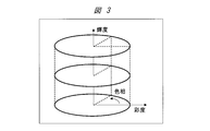
- FIG. 3 is a diagram showing an example of a color space of a video.
- FIG. 3 shows an example expressing the HLS color space.
- the direction of rotation of the cylinder circle corresponds to hue
- the direction of the circle diameter corresponds to saturation
- the height direction of the cylinder corresponds to luminance.
- a method of expressing the HLS color space there is also a model in which two cones in which the diameter of saturation is reduced toward the high luminance side and the low luminance side centering on the intermediate luminance are overlapped.
- a cylindrical model will be used for explanation.
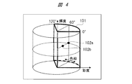
- FIG. 4 is a diagram illustrating an example in which correction is performed by limiting the color space of the video.
- FIG. 4 shows an example in which correction is limited to the space indicated by the bold line 101 in the entire color space.
- the limited correction region 101 is an example that is between 0 ° and 120 ° of hue and is not limited to the luminance direction and the saturation direction.
- characteristics for performing each correction of hue, saturation, and luminance for the correction region 101 limited in this color space will be described.
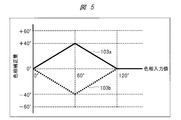
- FIG. 5 is a diagram illustrating an example of a hue correction characteristic of an image.
- FIG. 5 shows an example of hue correction characteristics centered on the correction point 102a shown in FIG. 4.
- the horizontal axis represents the hue input value before correction
- the vertical axis represents the hue correction amount.
- a solid line 103a indicates that a video component having a hue input value of 60 ° of the input video is corrected in the + 40 ° direction.
- the solid line 103a in the example of the characteristic that the correction amount decreases as it goes away from the hue input value 60 ° so that the correction amount becomes zero at the hue input value 0 ° and the hue input value 120 ° of the input video. is there.
- the correction characteristic of the solid line 103a is a mountain-shaped and linear characteristic having a peak around the hue input value of 60 °.
- a broken line 103b shows an example of characteristics for correcting the hue input value 60 ° portion of the input video in the ⁇ 40 ° direction.
- FIG. 6 shows the input / output characteristics of video when hue correction is performed using these characteristics.
- FIG. 6 is a diagram illustrating an example of video input / output characteristics when hue correction is performed, where the horizontal axis represents the hue input value and the vertical axis represents the hue output value.
- the characteristic when the hue is corrected in the positive direction is indicated by a solid line 103c
- the characteristic when the hue is corrected in the negative direction is indicated by a broken line 103d.
- the one-dot chain line in FIG. 6 shows the case without correction.
- the characteristic of the solid line 103c is a linear characteristic from a hue output value of 0 ° to 100 ° from a hue input value of 0 ° to 60 °, and further, a hue output value of 100 ° from a hue input value of 60 ° to 120 °. It becomes a linear characteristic from 120 ° to 120 °.
- the characteristic of the broken line 103d is a linear characteristic from a hue output value of 0 ° to 20 ° from a hue input value of 0 ° to 60 °, and further, a hue output value of 20 ° from a hue input value of 60 ° to 120 °. It becomes a linear characteristic from 120 ° to 120 °.
- the correction amount is reduced from the hue center to be corrected (60 ° in FIG. 5) toward the end direction (0 ° and 120 ° in FIG. 5) of the limited correction region 101. Since it is possible to prevent the step of the video signal from occurring at the joint with the hue range that is not subject to correction, natural color correction can be realized.
- FIG. 7 is a diagram illustrating an example of the saturation correction characteristic of the video.
- FIG. 7 shows an example of saturation correction characteristics at a hue of 60 ° and a saturation of 50% indicated by the correction point 102b on the color space shown in FIG.
- the horizontal axis is the hue input value of the video, and the vertical axis is the saturation correction amount.
- the characteristic indicated by the solid line 104 shows an example in which the saturation of the input image is corrected to 100% at the correction point 102b. In the hue direction, the correction is performed toward the hue 0 ° and the hue 120 ° of the input image. I try to reduce the amount.
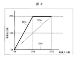
- FIG. 8 is a diagram illustrating an example of video input / output characteristics when saturation correction is performed, in which the horizontal axis represents a saturation input value and the vertical axis represents a saturation output value.
- the one-dot chain line 105a in FIG. 8 shows the case without correction
- the solid line 105b shows the result of correction with the characteristics of the solid line 104 in FIG. 7 (correction of saturation 50% to saturation 100%)
- the broken line 105c The result of correcting the saturation of 50% of the input video to 0% is shown.
- the characteristic of the solid line 105b is a linear characteristic from a saturation output value of 0% to 50%, and a saturation output value of 0% to 100%, and further, a saturation input value of 50% to 100%.
- a constant characteristic is obtained at an output value of 100%.
- the characteristic of the broken line 105c is a constant characteristic with a saturation output value of 0% from a saturation input value of 0% to 100%. Saturation correction is performed as described above.
- the saturation correction amount is decreased as the saturation of the input video is lowered, so that the correction amount of the low-saturation region where the color is hardly perceivable in the image before the correction is reduced. can do.
- the influence of the saturation adjustment at the first position where the saturation input value is 0% and the second position where the saturation input value is 50% is the second where the saturation input value is 50%.
- the first position where the saturation input value is 0% is smaller than the position.
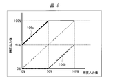
- FIG. 9 is a diagram illustrating an example of video input / output characteristics when luminance correction is performed at the correction point 102a.
- the horizontal axis represents the luminance input value and the vertical axis represents the luminance output value.
- the solid line 106a shows an example of correcting the luminance input value 50% to 100% and the broken line 106b shows an example of correcting the luminance input value 50% to 0% with respect to the characteristic without correction indicated by the one-dot chain line.
- the characteristic of the solid line 106a is a linear characteristic from a luminance input value of 50% to 100% when the luminance input value is 0% to 50%, and further, the luminance output value is 100% from a luminance input value of 50% to 100%.
- the characteristic of the broken line 106b is a constant characteristic at the luminance output value 0% from the luminance input value 0% to 50%, and further from the luminance output value 0% to 50% from the luminance input value 50% to 100%. It becomes the linear characteristic. Correction is performed with the characteristics shown in FIG. 9 according to the luminance input value.
- FIG. 10 shows an example of luminance correction characteristics according to the saturation input value.
- FIG. 10 is a diagram illustrating an example of the luminance correction characteristic of an image, where the horizontal axis represents the saturation input value and the vertical axis represents the luminance correction amount. As indicated by a solid line 107 in FIG. 10, correction is performed so that the luminance correction amount is 100% when the saturation input value is 100%, and the luminance correction amount is 0% when the saturation input value is 0%.
- the influence of the luminance adjustment is that the saturation input value is 0% than the position where the saturation input value is 100%. The position is smaller.
- Luminance correction is performed with correction characteristics obtained by multiplying the characteristics of the hue direction, luminance direction, and saturation direction described above.
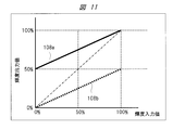
- FIG. 11 is a diagram illustrating an example of input / output characteristics of another video when luminance correction is performed, in which the horizontal axis represents the luminance input value and the vertical axis represents the luminance output value. In the case of FIG.
- the characteristic of the solid line 108a is a linear characteristic from the luminance output value 50% to 100% when the luminance input value is 0% to 100%.
- the characteristic of the broken line 108b is a linear characteristic from the luminance output value 0% to 50% when the luminance input value is 0% to 100%.
- natural correction can be performed in the correction of hue, saturation, and luminance in a desired color space. That is, it is possible to provide a video display technique that minimizes side effects caused by color correction. As a result, desired color correction can be performed while minimizing side effects caused by color correction.
- correction for one limited area has been described. However, a plurality of limited areas can be set and correction can be performed simultaneously. Moreover, it may be limited to different hue ranges, and the color space in the luminance direction and saturation direction may be limited.
- the video display device includes an input signal processing unit 11, a video correction unit 100, and an optical system device 200.
- the image correction unit 100 divides a color space around the three axes of luminance (or lightness), saturation, and hue into a plurality of regions in the color adjustment processing for the input image, and each of the plurality of regions Luminance adjustment (or lightness adjustment), saturation adjustment, and hue adjustment can be performed for each region.
- one area of the plurality of areas includes a first position where the saturation before correction is the first value, and a second position where the saturation before correction is higher than the first value.
- the second embodiment is an example in which a process with a limitation is applied so that correction is not performed on an image lower than a predetermined saturation.
- FIG. 12 is a diagram illustrating an example of a color space of a video.
- a limited correction area 109 is defined in the HLS color space, and an area to be corrected is shown.
- hue correction, saturation correction, and luminance correction are not performed below a predetermined saturation S1
- the limited correction area 109 is an area excluding a saturation area lower than the saturation S1. .
- each correction of hue, saturation, and luminance will be described.
- hue correction is performed at the correction point 110a shown in FIG. 12 with the characteristics described with reference to FIGS.
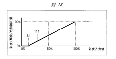
- a saturation direction control characteristic as shown in FIG. 13, a characteristic obtained by multiplying the characteristic that becomes zero at a predetermined saturation S1 by the hue input / output characteristic shown in FIG. Hue correction characteristics.
- FIG. 13 is a diagram illustrating an example of video correction characteristics, where the horizontal axis represents the saturation input value and the vertical axis represents the saturation / luminance / hue correction amount.
- a saturation input value of about 10% is shown as an example of the predetermined saturation S1.
- the position of the saturation S1 corresponds to the correction point 110c shown in FIG.
- hue correction is not performed for an image having a saturation smaller than the saturation S1, and a step of saturation in the color space with an area below the saturation S1 is suppressed. Color correction can be realized.
- the characteristic that changes from 0% to 100% in the correction amount shown in FIG. 13 may not be a linear characteristic, and may be a characteristic that decreases from the saturation input value 100% toward the saturation S1.
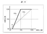
- FIG. 14 shows input / output characteristics for saturation correction in the present embodiment.
- FIG. 14 is a diagram illustrating an example of video input / output characteristics when saturation correction is performed, where the horizontal axis represents the saturation input value and the vertical axis represents the saturation output value. The characteristic of the solid line 105d shown in FIG.
- the 14 is an example of correcting the video component having the saturation input value of 50% to the saturation of 100% with respect to the characteristic without correction shown by the one-dot chain line 105a.
- the characteristic is such that the correction amount becomes zero. Accordingly, saturation correction is not performed for an image having saturation smaller than saturation S1, and a step of saturation with an area below saturation S1 can be suppressed, so that natural color correction can be realized.
- natural correction can be performed in the correction of hue, saturation, and luminance in a desired color space.
- desired color correction can be performed after excluding low-saturation regions (regions with saturation S1 or less in this embodiment) in which almost no color can be perceived in the pre-correction image from the correction region.
- low-saturation regions regions with saturation S1 or less in this embodiment
- the correction for one limited area has been described in the second embodiment, a plurality of limited areas can be set and correction can be performed simultaneously. Further, it may be limited to different hue ranges, and the color space in the luminance direction may be limited.
- the third embodiment is an example of a case where at least a red region, a blue region, and a green region are included in a plurality of regions obtained by dividing the color space.
- the HLS color space shown in FIG. 3 is divided into six spaces of red, yellow, green, cyan, blue, and magenta every 60 ° along the hue direction, and a predetermined color
- An example in which an area where the saturation of the input video is lower than the degree S2 is treated as colorless (white) is shown.
- FIG. 15 is a diagram showing an example of a color space 112 of an image. An upper part shows an outline of division of the color space 112 at that time, and a lower part shows a color space viewed from the upper surface of the color space 112, that is, the direction of the luminance axis. It shows how it was divided.
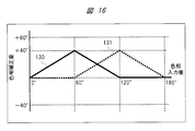
- FIG. 16 is a diagram illustrating an example of the hue correction characteristic of an image, where the horizontal axis represents the hue input value and the vertical axis represents the hue correction amount.
- a solid line 130 indicates a correction characteristic at a hue input value of 60 °
- a broken line 131 indicates a correction characteristic at a hue input value of 120 °, which is an example of correction in the + 40 ° direction. It does not matter if it is a value.
- the correction characteristic affects the range from 0 ° to 120 °.
- the correction characteristic is 60 °.
- the range of influence of this correction is not limited to this.
- correction characteristics are set for other hues.
- FIG. 17 shows correction characteristics when saturation correction is performed.
- FIG. 17 is a diagram illustrating an example of correction characteristics in the hue direction when saturation correction is performed, in which the horizontal axis represents the hue input value and the vertical axis represents the saturation correction amount.
- the solid line 140 indicates the saturation correction characteristic at the hue input value of 60 °
- the broken line 141 indicates the saturation correction characteristic at the hue input value of 120 °, which is 100% at the hue input value of 60 ° and 120 °, respectively.
- the hue correction when correcting the saturation of the hue input value of 60 °, the correction characteristic affects the range from 0 ° to 120 °, and when correcting the saturation of the hue input value of 120 °, the correction is performed.
- the characteristic affects the range of 60 ° to 180 °, but the range of influence of this correction is not limited to this.
- the luminance correction of the six colored regions is a correction characteristic obtained by multiplying the luminance correction characteristic described with reference to FIG. 9 or FIG. 11 by a correction characteristic with saturation S2 or higher shown in FIG.
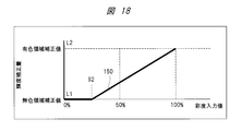
- FIG. 18 is a diagram illustrating an example of the luminance correction characteristic of an image, where the horizontal axis represents the saturation input value and the vertical axis represents the luminance correction amount.
- the correction characteristics indicated by the solid line 150 are such that the luminance correction amount at saturation S2 is the luminance correction value L1 for the colorless region, and the luminance correction amount at 100% saturation is the luminance correction value L2 for the colored region.
- the correction characteristic at saturation S2 or higher is indicated by a straight line.
- the correction characteristic is not limited to this, but the luminance correction value L1 at saturation S2 and the luminance correction value at saturation 100%. Any characteristic that is L2 may be used.
- FIG. 19 is a diagram illustrating an example of a color adjustment menu screen.
- the color adjustment menu screen is displayed on a display device included in the optical system device 200 of the video display device.
- the display device is attached with a remote controller for performing operations.
- the user selects the color correction 120 with the cursor etc. from the color adjustment menu screen displayed on the screen of the display device by using the menu button on the remote controller and presses the enter button.
- the items of hue 121a, saturation 121b, and luminance 121c appear on the screen.
- an adjustment menu 122 for six colors appears.
- the arrow adjustment cursor indicates the current correction position as shown in FIG.
- the user can adjust the desired color correction degree by moving the cursor by operating the remote controller or the like.
- a determination operation is performed. In this way, by performing adjustment while displaying on the screen, the user can perform image quality adjustment while checking the adjustment state of the entire hue.
- the hue adjustment menu 122 adjusts each desired color by selecting a desired color adjusted by an operation of a remote controller or the like.
- the hue adjustment has been described above. Similarly, when the saturation 121b and the luminance 121c are selected, an adjustment menu for each of the six color areas is displayed by the selection operation of the remote controller or the like, and the adjustment is performed by the same adjustment cursor operation. This makes it easy for the user to adjust the image quality. When shifting from hue adjustment to saturation adjustment or brightness adjustment, a return operation is performed.
- FIG. 20 shows an example in which an arrangement corresponding to the color space described with reference to FIG. 15 is displayed on the screen.
- a colorless area is arranged in the center, and six colored areas are arranged around the center. Yes.
- the user selects a desired color from this display by operating the remote controller or the like. With such a display, the user can easily grasp the positional relationship between the entire color space and individual colors.
- an adjustment menu shown in FIG. 21 appears.
- the menu of FIG. 21 may be displayed after erasing FIG. 20, or may be displayed so as to be inserted into the screen simultaneously with the menu of FIG.
- the hue, saturation, and luminance related to red are individually selected with a cursor and adjusted.
- the hue, saturation, and luminance of a desired color can be adjusted within one screen, and usability can be improved.
- the image quality adjustment is performed by the same operation.
- colorless only the brightness adjustment cursor is displayed so that it can be operated. The user can easily adjust the image quality by using the color adjustment menu screen described above.
- the color space is divided and the region where the saturation of the input video is lower than the predetermined saturation S2 is treated as colorless.
- the colorless area may be defined in an easy-to-understand manner such as white or gray.
- the image is divided into six regions in the hue direction, but the present invention is not limited to this.
- the plurality of regions obtained by dividing the color space include at least a red region, a blue region, and a green region.
- Luminance adjustment (or brightness adjustment), saturation adjustment, and hue adjustment for each of the red, blue, and green areas are performed in the red, blue, and green areas.
- the influence on the low-saturation region can be reduced as compared with the high-region region.
- a plurality of regions obtained by dividing the color space and a video region lower than the predetermined saturation S2 are provided, and the luminance (or lightness) of the video region lower than the saturation S2 is provided. Only adjustments can be made.
- the adjustment level of the color adjustment of the video display state in the optical system 200 on the color adjustment menu screen is set to the brightness (or lightness) and saturation in each of a plurality of areas obtained by dividing the color space. Adjustments can be made for degree and hue.
- FIG. 22 is a diagram illustrating an example of another configuration of the video correction unit 100.
- the video correction unit 100 includes an HLS conversion unit 131, an overall color correction unit 132, a local color correction unit 133, and an RGB conversion unit 134.
- the overall color correction unit 132 is a unit that receives the video signal converted into the HLS format from the HLS conversion unit 131 and performs uniform color correction on the entire color space of the video signal.
- the local color correction unit 133 is a unit that receives the video signal from the overall color correction unit 132 and the control signal 25 and corrects the video signal for a desired color based on the control signal 25.
- the HLS converter 131 and the RGB converter 134 are the same as the HLS converter 21 and the RGB converter 24 of the first embodiment.
- the internal video signal 12 is converted into the HLS format by the HLS conversion unit 131 and input to the overall color correction unit 132.
- the overall color correction unit 132 performs uniform color correction over the entire color space of the video, for example, correction of hue, saturation, brightness, contrast, and the like.
- the local color correction unit 133 corrects a desired color based on the control signal 25.
- a desired color is designated, and hue, saturation, and luminance are corrected.
- the RGB converter 134 outputs the video corrected as described above in the RGB format.
- the correction by limiting the color space by the local color correction unit 133 is performed. be able to.
- Embodiment 4 after adjusting the luminance (or lightness), saturation, and hue of the entire color space of the input video, the color for each of a plurality of regions obtained by dividing the color space. Adjustments can be made.
- the correction characteristics described in the above embodiment are shown as an example, and may not be linear characteristics, but may be non-linear characteristics in consideration of display device characteristics and human visual characteristics.
- the correction characteristic has been described with a mountain-shaped characteristic having a peak at the center of the correction, if the correction amount has a maximum value in the range including the correction center and the correction amount is zero outside the influence range of the correction, Therefore, for example, the trapezoidal characteristics can provide the same effects as those described in the above embodiment.
- each of the above-described configurations may be configured such that a part or all of the configuration is configured by hardware, or is realized by executing a program by a processor.
- control lines and information lines indicate what is considered necessary for the explanation, and not all the control lines and information lines on the product are necessarily shown. Actually, it may be considered that almost all the components are connected to each other.
Landscapes
- Engineering & Computer Science (AREA)
- Multimedia (AREA)
- Signal Processing (AREA)
- Physics & Mathematics (AREA)
- General Physics & Mathematics (AREA)
- Theoretical Computer Science (AREA)
- Controls And Circuits For Display Device (AREA)
- Image Processing (AREA)
Abstract
色補正により生ずる副作用を最小限にする映像表示技術である。映像表示装置は、映像入力部と、映像入力部に入力された映像の色調整処理を行う色調整部と、色調整部で色調整した映像を表示する表示部と、を備える。色調整部は、映像についての色調整処理において、輝度または明度、彩度、および色相の3軸を軸とする色空間を複数の領域に分割し、複数の領域の各領域について輝度調整または明度調整、彩度調整、および色相調整をそれぞれ行うことが可能である。色空間において、複数の領域の一の領域には、補正前の彩度が第1の値である第1の位置と、補正前の彩度が第1の値よりも高い第2の値である第2の位置があり、輝度調整または明度調整、彩度調整、および色相調整の影響は、第2の位置よりも第1の位置の方が小さい。
Description
本発明は、映像表示装置、およびこの映像表示装置における映像表示方法に関する。
近年、撮像装置や表示装置の性能向上が進んでおり、映像信号の品質が向上するとともにフォーマットも多様化している。例えば、表示装置としては、光源にLEDが用いられることで、従来の蛍光管が用いられる場合と比較して、より幅広い色の表現が可能になっている。そのため、同じ映像信号を異なる表示装置に表示した場合に、異なる画質として表示されることがあり、画質調整によりできるだけ近い画質として表示することが望まれる。
また、その際にも表示装置の性能は、出来る限り活用しつつ補正する必要がある上、画質の好みは個人ごとに異なるため、表示装置ごとの画質調整とともに、ユーザーが好みに応じて調整できる画質調整機能が必要である。これを目的として、表示装置において、映像補正を行うことで実現する技術が開発されている。
例えば、特許文献1には、映像信号を輝度、色相、彩度の各要素に分け、それぞれの要素の所定範囲を指定して、特定の色補正を行う技術が開示されている。
上記特許文献1では、ユーザーが所望の色を指定し、指定した色を好みに応じて補正できるようにしているが、彩度に応じた補正量については考慮されていない。例えば、指定した色領域に、色が薄く、白色に近い領域を含む場合に、その領域に色がついてしまう場合があった。
人間の視覚特性としては、周辺との対比で色や明るさを知覚することが知られているが、例えば、白色に近い表示領域の周囲に、色が鮮やかな部分がある場合、白色に近い領域は白色または無色として知覚される。このため、色補正によって白色に近い領域の彩度が上がり、色が濃くなってしまうと違和感が生ずる場合があった。
本発明の目的は、色補正により生ずる副作用を最小限にする映像表示技術を提供することである。
本発明の前記ならびにその他の目的と新規な特徴は、本明細書の記述および添付図面から明らかになるであろう。
本願において開示される発明のうち、代表的なものの概要を簡単に説明すれば、次のとおりである。
一実施の形態における映像表示装置は、入力映像の色調整処理が可能な映像表示装置である。前記映像表示装置は、映像入力部と、前記映像入力部に入力された映像の色調整処理を行う色調整部と、前記色調整部で色調整した映像を表示する表示部と、を備える。前記色調整部は、前記映像についての色調整処理において、輝度または明度、彩度、および色相の3軸を軸とする色空間を複数の領域に分割し、前記複数の領域の各領域について輝度調整または明度調整、彩度調整、および色相調整をそれぞれ行うことが可能である。前記色空間において、前記複数の領域の一の領域には、補正前の彩度が第1の値である第1の位置と、補正前の彩度が前記第1の値よりも高い第2の値である第2の位置があり、前記輝度調整または前記明度調整、前記彩度調整、および前記色相調整の影響は、前記第2の位置よりも前記第1の位置の方が小さい。
一実施の形態における映像表示方法は、入力映像の色調整処理が可能な映像表示装置における映像表示方法である。前記映像表示方法は、映像入力ステップと、前記映像入力ステップで入力された映像の色調整処理を行う色調整ステップと、前記色調整ステップで色調整した映像を表示する表示ステップと、を備える。前記色調整ステップでは、前記映像についての色調整処理において、輝度または明度、彩度、および色相の3軸を軸とする色空間を複数の領域に分割し、前記複数の領域の各領域について輝度調整または明度調整、彩度調整、および色相調整をそれぞれ行うことが可能である。前記色空間において、前記複数の領域の一の領域には、補正前の彩度が第1の値である第1の位置と、補正前の彩度が前記第1の値よりも高い第2の値である第2の位置があり、前記輝度調整または前記明度調整、前記彩度調整、および前記色相調整の影響は、前記第2の位置よりも前記第1の位置の方が小さい。
本願において開示される発明のうち、代表的なものによって得られる効果を簡単に説明すれば以下の通りである。
一実施の形態によれば、色補正により生ずる副作用を最小限にする映像表示技術を提供することができる。
以下の実施の形態においては、便宜上その必要があるときは、複数のセクションまたは実施の形態に分割して説明するが、特に明示した場合を除き、それらは互いに無関係なものではなく、一方は他方の一部または全部の変形例、詳細、補足説明などの関係にある。また、以下の実施の形態において、要素の数など(個数、数値、量、範囲などを含む)に言及する場合、特に明示した場合および原理的に明らかに特定の数に限定される場合などを除き、その特定の数に限定されるものではなく、特定の数以上でも以下でも良い。
さらに、以下の実施の形態において、その構成要素(要素ステップなども含む)は、特に明示した場合および原理的に明らかに必須であると考えられる場合などを除き、必ずしも必須のものではないことは言うまでもない。同様に、以下の実施の形態において、構成要素などの形状、位置関係などに言及するときは、特に明示した場合および原理的に明らかにそうでないと考えられる場合などを除き、実質的にその形状などに近似または類似するものなどを含むものとする。このことは、上記数値および範囲についても同様である。
[実施の形態の概要]
[実施の形態の概要]
まず、実施の形態の概要について説明する。本実施の形態の概要では、一例として、括弧内に各実施の形態の対応する構成要素および符号などを付して説明する。
一実施の形態における映像表示装置は、入力映像の色調整処理が可能な映像表示装置である。前記映像表示装置は、映像入力部(入力信号処理部11)と、前記映像入力部に入力された映像の色調整処理を行う色調整部(映像補正部100)と、前記色調整部で色調整した映像を表示する表示部(光学系装置200)と、を備える。前記色調整部は、前記映像についての色調整処理において、輝度または明度、彩度、および色相の3軸を軸とする色空間を複数の領域に分割し、前記複数の領域の各領域について輝度調整または明度調整、彩度調整、および色相調整をそれぞれ行うことが可能である。前記色空間において、前記複数の領域の一の領域には、補正前の彩度が第1の値である第1の位置と、補正前の彩度が前記第1の値よりも高い第2の値である第2の位置があり、前記輝度調整または前記明度調整、前記彩度調整、および前記色相調整の影響は、前記第2の位置よりも前記第1の位置の方が小さい。
一実施の形態における映像表示方法は、入力映像の色調整処理が可能な映像表示装置における映像表示方法である。前記映像表示方法は、映像入力ステップ(入力信号処理部11における動作)と、前記映像入力ステップで入力された映像の色調整処理を行う色調整ステップ(映像補正部100における動作)と、前記色調整ステップで色調整した映像を表示する表示ステップ(光学系装置200における動作)と、を備える。前記色調整ステップでは、前記映像についての色調整処理において、輝度または明度、彩度、および色相の3軸を軸とする色空間を複数の領域に分割し、前記複数の領域の各領域について輝度調整または明度調整、彩度調整、および色相調整をそれぞれ行うことが可能である。前記色空間において、前記複数の領域の一の領域には、補正前の彩度が第1の値である第1の位置と、補正前の彩度が前記第1の値よりも高い第2の値である第2の位置があり、前記輝度調整または前記明度調整、前記彩度調整、および前記色相調整の影響は、前記第2の位置よりも前記第1の位置の方が小さい。
以下、上述した実施の形態の概要に基づいた各実施の形態を図面に基づいて詳細に説明するが、本発明は必ずしもこれらの実施の形態に限定されるものではない。なお、実施の形態を説明するための各図面において、同一の部材には原則として同一の符号を付し、その繰り返しの説明は省略する。
[実施の形態1]
[実施の形態1]
実施の形態1における映像表示装置および映像表示方法について、図1~図11を用いて説明する。
本実施の形態では、色補正機能を備える映像表示装置をプロジェクタの構成にて説明する。色補正機能は、入力映像の色調整処理を行う色調整機能を含むものとする。なお、以下では、フロントプロジェクタの例で説明するが、その形態は、リヤプロジェクションテレビでもよい。また、液晶ディスプレイ、プラズマディスプレイ、有機ELディスプレイなどの直視平面ディスプレイを用いた表示装置でも構わない。この点については、以降のいずれの実施の形態でも同様である。
<映像表示装置>
<映像表示装置>
本実施の形態における映像表示装置について、図1を用いて説明する。図1は、本実施の形態における映像表示装置の構成の一例を示す図である。
本実施の形態における映像表示装置は、入力信号処理部11と、映像補正部100と、タイミング制御部14と、光学系装置200とで構成される。入力信号処理部11は、入力映像信号10を入力とし、映像のフォーマットに応じて所定の処理を施し、RGB形式の内部映像信号12に変換する手段である。映像補正部100は、内部映像信号12および制御信号25を入力とし、内部映像信号12を制御信号25に基づいて補正して補正映像信号13を出力する手段である。タイミング制御部14は、補正映像信号13を入力とし、補正映像信号13を表示画面の水平・垂直同期信号に基づいて制御して表示制御信号15を生成する手段である。
光学系装置200は、映像を表示する装置であり、光源203と、パネル202と、レンズ201とで構成される。光源203は、スクリーンへ映像を投影するための光線を照射する手段である。パネル202は、表示制御信号15を入力とし、光源203からの光線の階調を画素毎に調整し、投射映像を作成する手段である。レンズ201は、パネル202からの投射映像をスクリーンに拡大投影するための手段である。
なお、映像表示装置が、液晶ディスプレイ、プラズマディスプレイ、有機ELディスプレイなどの直視平面ディスプレイである場合は、光学系装置200のレンズ201は不要である。ユーザーはパネル202を直視することとなる。
本構成例において、映像補正部100の処理は、制御信号25により補正の特性が制御される。この制御信号25は、例えば、ユーザーによるリモコンや表示装置のボタン操作等に基づき映像を補正するための制御信号である。このため、本実施の形態における映像表示装置には、リモコンや表示装置なども含まれている。
以上のような構成による映像表示装置の動作は、まず、入力信号処理部11において、入力映像信号10を入力とし、映像のフォーマットに応じて、例えばIP変換、スケーラ等の処理を施し、RGB形式の内部映像信号12に変換する。さらに、映像補正部100において、内部映像信号12および制御信号25を入力とし、内部映像信号12を制御信号25に基づいて補正して補正映像信号13を出力する。さらに、タイミング制御部14において、補正映像信号13を入力とし、補正映像信号13を表示画面の水平・垂直同期信号に基づいて制御して表示制御信号15を生成する。そして、光学系装置200において、パネル202が、表示制御信号15を入力とし、光源203からの光線の階調を画素毎に調整し、投射映像を作成し、この投射映像をレンズ201を介してスクリーンに拡大投影する。
本実施の形態における映像表示装置の構成において、入力信号処理部11は映像入力部の一例であり、映像補正部100は映像入力部に入力された映像の色調整処理を行う色調整部の一例であり、光学系装置200は色調整部で色調整した映像を表示する表示部の一例である。また、本実施の形態における映像表示装置の動作において、入力信号処理部11における動作は映像入力ステップの一例であり、映像補正部100における動作は色調整ステップの一例であり、光学系装置200における動作は表示ステップの一例である。以下において、映像補正部100の構成および動作について、詳細に説明する。
<映像補正部>
<映像補正部>
次に、前述した映像補正部100の構成について、図2を用いて説明する。図2は、本実施の形態における映像補正部100の構成の一例を示す図である。
映像補正部100は、HLS変換部21と、色補正部22a,22b,22c,22d,22e,22fと、合成部23と、RGB変換部24とで構成される。HLS変換部21は、内部映像信号12を入力とし、RGB形式からHLS形式への変換を行う手段である。色補正部22a,22b,22c,22d,22e,22fは、HLS形式に変換された映像信号と制御信号25とを入力とし、この映像信号を、制御信号25により設定される補正特性に基づき、それぞれ異なる色空間について制御信号25に基づく色補正を行う手段である。合成部23は、色補正処理がなされた映像信号を入力とし、この映像信号を合成する手段である。RGB変換部24は、合成された映像信号を入力とし、この映像信号をRGB形式に変換して補正映像信号13として出力する手段である。
以上のような構成による映像補正部100の動作は、まず、HLS変換部21で、内部映像信号12を、RGB形式からHLS形式への変換を行う。HLS形式の信号は、映像の色相(Hue)、彩度(Saturation)、輝度(Luminance)で表現するものである。なお、本実施の形態では、一例としてHLS形式を用いて説明を行うが、他にも、色相(Hue)、彩度(Saturation)、明度(Value)で表すHSV形式等でも構わない。
さらに、HLS形式に変換された映像信号は、色補正部22a~22fにて、制御信号25により設定される補正特性に基づき、それぞれ異なる色空間について制御信号25に基づく色補正がなされる。そして、色補正処理がなされた映像信号は、合成部23により合成された後、RGB変換部24によりRGB形式に変換されて補正映像信号13として出力される。
本構成例において、色補正部22a~22fは、色補正部(1)~色補正部(6)の6個設けているが、これに限ったものではない。また、色補正部22a~22fと合成部23とを組み合わせた構成についても、図2の構成に限ったものではなく、異なる1つ以上の色空間に分けて、それぞれ所定の色補正を行えるものであればよい。
<色補正動作>
<色補正動作>
次に、本実施の形態の色補正動作について、図3~図11を用いて説明する。映像の色空間は、輝度(または明度)、彩度、および色相の3軸を軸とする色空間である。
まず、図3は、映像の色空間の一例を示す図である。図3では、HLS色空間を表現した例を示している。円柱の円の回転方向が色相、円の径の方向が彩度、円柱の高さ方向が輝度に対応する。なお、HLS色空間の表し方として、中間輝度を中心として、高輝度側と低輝度側とに向けて彩度の径が縮小する2つの円錐を重ねたモデルもあるが、本実施の形態では説明の簡単化のため、円柱モデルを用いて説明する。
以下、色空間を図3のモデルに対応させて説明する。図4は、映像の色空間を限定して補正する場合の一例を示す図である。図4では、色空間全体のうち、101の太線で示した空間に限定して補正する例を示したものである。限定した補正領域101は、色相の0°から120°の間にあり、輝度方向および彩度方向には限定していない一例である。以下、この色空間の限定した補正領域101について、色相、彩度、輝度の各補正を行う特性の一例を説明する。
まず、色相補正の一例を説明する。図5は、映像の色相補正特性の一例を示す図である。図5では、図4に示した補正ポイント102aを中心とした色相補正特性の一例を示しており、横軸が補正前の色相入力値、縦軸が色相補正量を表している。実線103aは、入力映像の色相入力値60°の映像成分を+40°方向に補正することを示している。実線103aに示すように、入力映像の色相入力値0°と色相入力値120°とでは補正量をゼロとするように、色相入力値60°から離れるごとに補正量が減る特性とした例である。すなわち、実線103aの補正特性は、色相入力値60°を中心にピークを持つ山形でリニアな特性である。同様に、入力映像の色相入力値60°の部分を-40°方向に補正する特性例を破線103bで示している。
この特性で、色相補正を行った場合の映像の入出力特性を図6に示す。図6は、色相補正を行った場合の映像の入出力特性の一例を示す図であり、横軸が色相入力値、縦軸が色相出力値を表している。図6では、図5と同様に、色相をプラス方向に補正する際の特性を実線103c、マイナス方向に補正する際の特性を破線103dで示している。図6の1点鎖線は補正無しの場合を示している。例えば、実線103cの特性は、色相入力値0°から60°までは色相出力値0°から100°までのリニアな特性となり、さらに、色相入力値60°から120°までは色相出力値100°から120°までのリニアな特性となる。また、破線103dの特性は、色相入力値0°から60°までは色相出力値0°から20°までのリニアな特性となり、さらに、色相入力値60°から120°までは色相出力値20°から120°までのリニアな特性となる。
図5に示すように、補正する色相中心(図5では60°)から限定した補正領域101の端方向(図5では0°と120°)に向かって補正量を減らす特性とすることにより、補正対象外の色相範囲との繋ぎ目に映像信号の段差が生じないようにできるので、自然な色補正が実現できる。
次に、彩度補正の一例を説明する。図7は、映像の彩度補正特性の一例を示す図である。図7では、図4に示した色空間上の補正ポイント102bで示す色相60°、彩度50%における彩度補正特性の一例を示している。横軸は映像の色相入力値、縦軸が彩度補正量である。実線104で示す特性は、補正ポイント102bにおいて、入力映像の彩度50%を100%まで補正する一例を示しており、色相方向には、入力映像の色相0°および色相120°に向かって補正量を小さくするようにしている。
この特性で補正した映像の彩度の入出力特性を図8に示している。図8は、彩度補正を行った場合の映像の入出力特性の一例を示す図であり、横軸が彩度入力値、縦軸が彩度出力値を表している。図8の1点鎖線105aは補正無しの場合を示しており、実線105bは図7の実線104の特性(彩度50%を彩度100%に補正)で補正した結果を示し、破線105cは入力映像の彩度50%を0%に下げる方向に補正した結果を示している。例えば、実線105bの特性は、彩度入力値0%から50%までは彩度出力値0%から100%までのリニアな特性となり、さらに、彩度入力値50%から100%までは彩度出力値100%で一定の特性となる。また、破線105cの特性は、彩度入力値0%から100%までは彩度出力値0%で一定の特性となる。以上のように彩度補正を行う。
このように彩度補正を行うことで、まず、図4に示す限定した補正領域101の範囲外、つまり彩度補正しない色空間との繋ぎ目に、彩度の段差が生じないようにできるので、自然な色補正が実現できる。さらに、図8の特性のように、入力映像の彩度が低くなるに従い、彩度補正量を小さくすることで、補正前の映像で色がほとんど知覚できない彩度の低い領域の補正量を小さくすることができる。例えば、図8において、彩度入力値0%の第1の位置と、彩度入力値50%の第2の位置とにおいて、彩度調整の影響は、彩度入力値50%の第2の位置よりも彩度入力値0%の第1の位置の方が小さくなっている。すなわち、彩度入力値が50%から0%に小さくなるに従って、彩度調整の影響が小さくなっている。これにより、補正前の映像で色がほとんど知覚できない彩度の低い領域の補正量を小さくすることができ、ほとんど無色のような映像領域の色が濃くなってしまうなどにより生ずる違和感を減ずることができる。
次に、輝度補正の一例を説明する。まず、輝度補正においても、補正の中心となる色相に対して、色相方向には図7に示したものと同様な特性で補正量を制御する。つまり、図4の補正ポイント102aの輝度補正を行う場合には、色相60°を最大補正量として色相0°、色相120°でゼロになるような特性となる。次に、図9は、補正ポイント102aにおける輝度補正を行った場合の映像の入出力特性の一例を示す図であり、横軸が輝度入力値、縦軸が輝度出力値を表している。1点鎖線で示す補正無しの特性に対して、実線106aは、輝度入力値50%を100%に補正する一例、破線106bは輝度入力値50%を0%に補正する一例を示している。例えば、実線106aの特性は、輝度入力値0%から50%までは輝度出力値50%から100%までのリニアな特性となり、さらに、輝度入力値50%から100%までは輝度出力値100%で一定の特性となる。また、破線106bの特性は、輝度入力値0%から50%までは輝度出力値0%で一定の特性となり、さらに、輝度入力値50%から100%までは輝度出力値0%から50%までのリニアな特性となる。輝度入力値に応じて図9に示した特性で補正を行う。
また、彩度入力値に応じた輝度の補正特性の一例を図10に示す。図10は、映像の輝度補正特性の一例を示す図であり、横軸が彩度入力値、縦軸が輝度補正量を表している。図10に実線107で示したように、彩度入力値100%で輝度の補正量を100%とし、彩度入力値0%で輝度の補正量が0%となるように補正する。図10において、例えば、彩度入力値0%の位置と、彩度入力値100%の位置とにおいて、輝度調整の影響は、彩度入力値100%の位置よりも彩度入力値0%の位置の方が小さくなっている。すなわち、彩度入力値が100%から0%に小さくなるに従って、輝度調整の影響が小さくなっている。以上に説明した色相方向、輝度方向、彩度方向の各特性を乗じた補正特性で輝度補正を行う。この輝度補正により、前記の色相補正、彩度補正と同様に、図4に示す限定した補正領域101の範囲外、つまり補正しない色空間との繋ぎ目に輝度の段差が生じないようにできるので、自然な補正が実現できる。
なお、図9で説明した輝度補正では、輝度を上げる場合は、入力=出力の特性、つまり傾き1の特性に対して、傾きを変えずに入力にオフセットを付加し、輝度を下げる場合はオフセットを差し引く特性としたが、図11に示すように、補正特性の傾きを変えることでもよい。図11は、輝度補正を行った場合の別の映像の入出力特性の一例を示す図であり、横軸が輝度入力値、縦軸が輝度出力値を表している。図11の場合は、輝度を上げる場合、実線108aに示すように輝度入力値0%に対して50%のオフセットを加え、輝度を下げる場合は、破線108bに示すように輝度入力値100%から50%のオフセットを差し引くことで実現する。例えば、実線108aの特性は、輝度入力値0%から100%までは輝度出力値50%から100%までのリニアな特性となる。また、破線108bの特性は、輝度入力値0%から100%までは輝度出力値0%から50%までのリニアな特性となる。
<実施の形態1の効果>
<実施の形態1の効果>
以上説明したように、本実施の形態1における映像表示装置および映像表示方法によれば、所望の色空間における色相、彩度、輝度の補正において、自然な補正を行うことができる。すなわち、色補正により生ずる副作用を最小限にする映像表示技術を提供することができる。この結果、色補正により生ずる副作用を最小限にしつつ、所望の色補正を行うことができるようになる。なお、本実施の形態1では、1つの限定領域についての補正について説明したが、複数の限定領域を設定し、同時に補正を行うこともできる。また、異なる色相範囲に限定してもよく、輝度方向や彩度方向の色空間を限定してもよい。
特に、本実施の形態1において、映像表示装置は、入力信号処理部11と、映像補正部100と、光学系装置200と、を備える。映像補正部100は、入力された映像についての色調整処理において、輝度(または明度)、彩度、および色相の3軸を軸とする色空間を複数の領域に分割し、複数の領域の各領域について輝度調整(または明度調整)、彩度調整、および色相調整をそれぞれ行うことが可能である。かつ、色空間において、複数の領域の一の領域には、補正前の彩度が第1の値である第1の位置と、補正前の彩度が第1の値よりも高い第2の値である第2の位置があり、輝度調整(または明度調整)、彩度調整、および色相調整の影響は、第2の位置よりも第1の位置の方を小さくすることができる。これにより、所望の色空間における色相、彩度、輝度(または明度)の補正において、自然な補正を行うことができる。
[実施の形態2]
[実施の形態2]
実施の形態2における映像表示装置および映像表示方法について、図12~図14を用いて説明する。本実施の形態2では、前記実施の形態1と異なる点を主に説明する。
<色補正動作>
<色補正動作>
本実施の形態2は、所定の彩度よりも低い映像に対して補正を行わないように限定を加えた処理を行う一例である。図12は、映像の色空間の一例を示す図である。図12では、HLS色空間において、限定した補正領域109を定めて、補正を行う領域を示している。まず、所定の彩度S1以下において、色相補正、彩度補正、輝度補正を行わないようにしており、限定した補正領域109は彩度S1よりも低い彩度領域を除いた領域となっている。以下、色相、彩度、輝度の各補正について説明する。
まず、色相補正は、図12に示す補正ポイント110aにおいては、図5および図6で説明した特性で色相補正を行う。ここで、本実施の形態2では、彩度方向の制御特性として、図13に示すように、所定の彩度S1でゼロとなる特性を図6に示す色相の入出力特性に乗じた特性を色相補正特性とする。図13は、映像の補正特性の一例を示す図であり、横軸が彩度入力値、縦軸が彩度/輝度/色相補正量を表している。図13に示す実線111の特性では、所定の彩度S1として、例えば彩度入力値10%程度を例に示している。この彩度S1の位置が、図12に示す補正ポイント110cに対応する。図13の特性を乗ずることで、彩度S1よりも彩度が小さな映像については色相補正をしないようにするとともに、彩度S1以下の領域との色空間の彩度の段差を抑制し、自然な色補正が実現できる。なお、図13に示す補正量0%から100%まで変化する特性は、リニアな特性でなくてもよく、彩度入力値100%から彩度S1に向けて減少する特性であればよい。
次に、彩度補正について、図12に示す補正ポイント110b(色相60°、彩度50%)における補正例を説明する。まず、彩度補正特性の色相方向については、図7で説明したように、入力映像の色相入力値60°で補正量を100%とし、入力映像の色相入力値0°および色相入力値120°で補正量をゼロとするように減少する特性とする。次に、図14に本実施の形態における彩度補正の入出力特性を示す。図14は、彩度補正を行った場合の映像の入出力特性の一例を示す図であり、横軸が彩度入力値、縦軸が彩度出力値を表している。図14に示す実線105dの特性では、1点鎖線105aで示す補正無しの特性に対して、彩度入力値50%の映像成分を彩度100%に補正する一例であり、入力の彩度S1において補正量がゼロとなるような特性とする。これにより、彩度S1よりも彩度が小さな映像については彩度補正をしないようにするとともに、彩度S1以下の領域との彩度の段差を抑制できるので、自然な色補正が実現できる。
次に、輝度補正については、図9または図11で説明した輝度補正特性に、図13に示した彩度方向の補正特性を乗じた補正特性とする。これにより、彩度S1よりも彩度が小さな映像については輝度補正をしないようにする。
<実施の形態2の効果>
<実施の形態2の効果>
以上説明したように、本実施の形態2における映像表示装置および映像表示方法によれば、所望の色空間における色相、彩度、輝度の補正において、自然な補正を行うことができる。特に、補正前の映像で色がほとんど知覚できない彩度の低い領域(本実施の形態では彩度S1以下の領域)を補正領域から除外した上で、所望の色補正を行うことができる。なお、本実施の形態2では、1つの限定領域についての補正について説明したが、複数の限定領域を設定し、同時に補正を行うこともできる。また、異なる色相範囲に限定してもよく、輝度方向の色空間を限定してもよい。
特に、本実施の形態2では、色空間を分割した複数の領域において、所定の彩度S1よりも低い映像領域に対しては輝度調整(または明度調整)、彩度調整、および色相調整の影響がない。これにより、彩度S1以下の領域を補正領域から除外した上で、所望の色補正を行うことができる。
[実施の形態3]
[実施の形態3]
実施の形態3における映像表示装置および映像表示方法について、図15~図21を用いて説明する。本実施の形態3では、前記実施の形態1と異なる点を主に説明する。
<色補正動作>
<色補正動作>
本実施の形態3は、色空間を分割した複数の領域に、少なくとも赤領域、青領域、および緑領域が含まれる場合の一例である。本実施の形態3では、図3に示したHLS色空間を、色相方向に沿って60°毎に、赤、イエロー、緑、シアン、青、マゼンタの6つの空間に分割するとともに、所定の彩度S2よりも入力映像の彩度が低い領域を無色(白)として扱う場合の一例を示している。図15は、映像の色空間112の一例を示す図であり、上段にその際の色空間112の分割概要を示し、下段に色空間112の上面、つまり輝度軸の方向から見た色空間を分割した様子を示している。
本実施の形態3において、色相方向に沿って6つに分割した各色の色相、彩度の補正については、前記実施の形態2で説明した動作例と同様に各領域の補正処理を行う。なお、この時の補正特性は、領域毎に異なってもよい。本実施の形態3における色相補正特性の一例を図16に示す。図16は、映像の色相補正特性の一例を示す図であり、横軸が色相入力値、縦軸が色相補正量を表している。図16では、実線130は色相入力値60°における補正特性、破線131は色相入力値120°における補正特性を示しており、それぞれ、+40°方向に補正する一例であるが、それぞれの値が異なる値でも構わない。
また、本実施の形態3では、色相入力値60°を補正する場合、補正特性は、0°から120°の範囲に影響し、色相入力値120°を補正する場合、補正特性は、60°から180°の範囲に影響するようにしているが、この補正の影響範囲はこれに限ったものではない。その他の色相についても同様に、補正特性を設定する。
次に、彩度補正を行った場合の補正特性を図17に示す。図17は、彩度補正を行った場合の色相方向の補正特性の一例を示す図であり、横軸が色相入力値、縦軸が彩度補正量を表している。図17では、実線140は色相入力値60°における彩度補正特性、破線141は色相入力値120°における彩度補正特性を示しており、それぞれ、色相入力値60°、120°において100%になるようにする。また、色相補正と同様に、色相入力値60°の彩度を補正する場合、補正特性は、0°から120°の範囲に影響し、色相入力値120°の彩度を補正する場合、補正特性は、60°から180°の範囲に影響するようにしているが、この補正の影響範囲はこれに限ったものではない。
一方、本実施の形態3では、無色領域についての輝度補正を可能とする。その際、有色の6領域の輝度補正については、図9または図11で説明した輝度補正特性に、図18に示す彩度S2以上の補正特性を乗じた補正特性とする。図18は、映像の輝度補正特性の一例を示す図であり、横軸が彩度入力値、縦軸が輝度補正量を表している。図18では、実線150で示す補正特性は、彩度S2における輝度補正量を、無色領域の輝度補正値L1とし、彩度100%における輝度補正量を、有色領域の輝度補正値L2とする。図18に示す実線150の特性では、彩度S2として、例えば彩度入力値25%程度を例に示している。なお、図18に示す実線150では、彩度S2以上における補正特性は直線で示しているが、これに限ったものではなく、彩度S2で輝度補正値L1、彩度100%で輝度補正値L2となる特性であればよい。
以上に説明したように無色領域を含めた7領域に分割することで、彩度がS2よりも高い有色領域と、彩度がS2よりも低い無色領域に対する有色領域の色補正に伴う副作用を抑制しつつ、自由に色補正することができるようになる。
<色調整メニュー画面>
<色調整メニュー画面>
次に、色補正の特性を設定する場合の色調整メニュー画面について説明する。図19は、色調整メニュー画面の一例を示す図である。色調整メニュー画面は、映像表示装置の光学系装置200に含まれる表示装置などに表示される。また、表示装置には、操作を行うリモコン等が付属されている。
まず、ユーザーは、リモコンのメニューボタンなどにより、表示装置の画面上に表示される色調整メニュー画面から色補正120をカーソル等で選択し、決定ボタンを押す。これにより、画面上には色相121a、彩度121b、輝度121cの項目が表れる。ここで、例えば、色相121aを選択すると、6つの色についての調整メニュー122が現れ、このうち、例えば、赤を選択すると、図19に示したように矢印の調整カーソルが現状の補正位置を示すとともに、ユーザーはこのカーソルをリモコン等による操作で移動させることで、所望の色補正度合いに合わせることができるようにする。所望の色補正度合いに合わせたら、決定操作を行う。このように、画面上に表示させて調整を行うことで、ユーザーは色相全体の調整状態を確認しながら、画質調整を行うことができるようになる。この色相の調整メニュー122は、リモコン等の操作で調整した所望の色を選択することで所望の各色の調整を行う。
以上は、色相調整について説明したが、彩度121b、輝度121cを選択した場合も同様に、リモコン等の選択操作によりそれぞれ6つの色領域についての調整メニューを出現させ、同様な調整カーソル操作により調整を可能とすることで、ユーザーの画質調整を容易にする。色相調整から彩度調整や輝度調整に移行するときは、戻る操作を行う。
次に、ユーザーの色調整メニュー画面の別の一例を図20、図21を用いて説明する。まず、ユーザーは、表示装置の画面上に表示される色調整メニュー画面からリモコン操作などにより色補正を選択したものとする。これにより、画面上には、図20に示す調整色の選択画面が表示される。図20は、図15を用いて説明した色空間に対応した配置を画面上に表示する際の一例を示しており、中央に無色領域を配置し、周囲に有色領域の6つを配置している。ユーザーは、この表示の中から所望の色をリモコン操作などにより選択する。このような表示により、色空間全体と個々の色の位置関係をユーザーが把握しやすくできる。
次に、所望の色、例えば赤を選択すると、図21の調整メニューが現れる。ここで、図21のメニューは、図20を消去後に表示してもよいし、図20のメニューと同時に画面中に挿入するように表示しても、どちらでもよい。図21は、赤色に関する色相、彩度、輝度を個々にカーソルで選択して調整するように配置している。このように、所望の色の色相、彩度、輝度の各調整を、1つの画面内で行うことができ、使い勝手を向上することができる。他の色を選択した場合も、同様な操作で画質調整を行うが、無色を選択した場合は、輝度の調整カーソルのみを操作可能なように表示する。以上説明した色調整メニュー画面により、ユーザーの画質調整を容易にできる。
<実施の形態3の効果>
<実施の形態3の効果>
以上説明したように、本実施の形態3における映像表示装置および映像表示方法によれば、色空間を分割するとともに、所定の彩度S2よりも入力映像の彩度が低い領域を無色として扱う場合に、色補正に伴う副作用を抑制しつつ、自由に色補正することができる。ここで、無色領域については、白色や灰色など、ユーザーが把握しやすい表現で定義してもよい。また、本実施の形態3では、色相方向に6領域に分割しているがこれに限ったものでない。
特に、本実施の形態3では、色空間を分割した複数の領域には、少なくとも赤領域、青領域、および緑領域が含まれる。赤領域、青領域、および緑領域のそれぞれに対する輝度調整(または明度調整)、彩度調整、および色相調整は、赤領域、青領域、および緑領域のぞれぞれの領域中において、彩度の高い領域よりも彩度の低い領域に対する影響を小さくすることができる。
また、本実施の形態3では、色空間を分割した複数の領域と、所定の彩度S2よりも低い映像領域とを設け、彩度S2よりも低い映像領域については、輝度(または明度)の調整のみを行うことができる。
また、本実施の形態3では、色調整メニュー画面において、光学系装置200での映像表示状態の色調整の調整度合いを、色空間を分割した複数の領域のそれぞれで輝度(または明度)、彩度、および色相について調整を行うことができる。
[実施の形態4]
[実施の形態4]
実施の形態4における映像表示装置および映像表示方法について、図22を用いて説明する。本実施の形態4では、前記実施の形態1と異なる点を主に説明する。
<映像補正部>
<映像補正部>
本実施の形態4として、映像補正部100の別の構成例を、図22を用いて説明する。図22は、映像補正部100の別の構成の一例を示す図である。
映像補正部100は、HLS変換部131と、全体色補正部132と、局所色補正部133と、RGB変換部134とで構成される。全体色補正部132は、HLS変換部131からのHLS形式に変換された映像信号を入力とし、この映像信号の色空間全体に一様な色補正を行う手段である。局所色補正部133は、全体色補正部132からの映像信号と制御信号25とを入力とし、この映像信号を、制御信号25に基づき、所望の色に対する補正を行う手段である。HLS変換部131およびRGB変換部134は、前記実施の形態1のHLS変換部21およびRGB変換部24と同様である。
この映像補正部100の動作では、まず、内部映像信号12は、HLS変換部131でHLS形式に変換され、全体色補正部132へ入力される。全体色補正部132では、映像の色空間全体に一様な色補正、例えば、色相、彩度、ブライトネス、コントラスト等の補正を行う。次に、局所色補正部133では、制御信号25に基づき、所望の色に対する補正を行う。この局所色補正部133の構成や、動作については、前記実施の形態1などと同様に、所望の色を指定し、色相、彩度、輝度の補正を行うものとする。RGB変換部134では、上記のように補正した映像をRGB形式で出力する。以上のように構成することで、画質全体の補正に加え、色空間を限定した補正を行うことができる。
<実施の形態4の効果>
<実施の形態4の効果>
以上説明したように、本実施の形態4における映像表示装置および映像表示方法によれば、全体色補正部132による画質全体の補正に加え、局所色補正部133による色空間を限定した補正を行うことができる。
特に、本実施の形態4では、入力された映像の色空間の全体に輝度(または明度)、彩度、および色相の調整を行った後に、色空間を分割した複数の領域の領域毎の色調整を行うことができる。
以上、本発明者によってなされた発明を実施の形態に基づき具体的に説明したが、本発明は前記実施の形態に限定されるものではなく、その要旨を逸脱しない範囲で種々変更可能であることはいうまでもない。
例えば、前記実施の形態において説明した補正特性は、一例として示しており、リニアな特性でなくてもよく、表示装置の特性や人の視覚特性を考慮したノンリニアな特性でもよい。また、補正特性としては、補正の中心にピークを持つ山形の特性で説明したが、補正の中心を含む範囲に補正量の最大値を持ち、補正の影響範囲外で補正量がゼロとなればよいので、例えば、台形の特性でも上記実施の形態で説明したものと同様な効果が得られる。
また、上記実施の形態は、本発明を分かり易く説明するために詳細に説明したものであり、必ずしも説明した全ての構成を備えるものに限定されるものではない。また、ある実施の形態の構成の一部を他の実施の形態の構成に置き換えることが可能であり、また、ある実施の形態の構成に他の実施の形態の構成を加えることも可能である。また、各実施の形態の構成の一部について、他の構成の追加・削除・置換をすることが可能である。
また、上記の各構成は、それらの一部又は全部が、ハードウェアで構成されても、プロセッサでプログラムが実行されることにより実現されるように構成されてもよい。また、制御線や情報線は説明上必要と考えられるものを示しており、製品上必ずしも全ての制御線や情報線を示しているとは限らない。実際には殆ど全ての構成が相互に接続されていると考えてもよい。
10 入力映像信号
11 入力信号処理部
12 内部映像信号
13 補正映像信号
14 タイミング制御部
15 表示制御信号
21 HLS変換部
22a~22f 色補正部
23 合成部
24 RGB変換部
25 制御信号
100 映像補正部
101 補正領域
200 光学系装置
201 レンズ
202 パネル
203 光源
11 入力信号処理部
12 内部映像信号
13 補正映像信号
14 タイミング制御部
15 表示制御信号
21 HLS変換部
22a~22f 色補正部
23 合成部
24 RGB変換部
25 制御信号
100 映像補正部
101 補正領域
200 光学系装置
201 レンズ
202 パネル
203 光源
Claims (12)
- 入力映像の色調整処理が可能な映像表示装置であって、
映像入力部と、
前記映像入力部に入力された映像の色調整処理を行う色調整部と、
前記色調整部で色調整した映像を表示する表示部と、
を備え、
前記色調整部は、
前記映像についての色調整処理において、輝度または明度、彩度、および色相の3軸を軸とする色空間を複数の領域に分割し、前記複数の領域の各領域について輝度調整または明度調整、彩度調整、および色相調整をそれぞれ行うことが可能であり、
前記色空間において、前記複数の領域の一の領域には、補正前の彩度が第1の値である第1の位置と、補正前の彩度が前記第1の値よりも高い第2の値である第2の位置があり、
前記輝度調整または前記明度調整、前記彩度調整、および前記色相調整の影響は、前記第2の位置よりも前記第1の位置の方が小さい、
映像表示装置。 - 請求項1に記載の映像表示装置であって、
前記色空間を分割した複数の領域には、少なくとも赤領域、青領域、および緑領域が含まれ、前記色調整部による前記赤領域、前記青領域、および前記緑領域のそれぞれに対する前記輝度調整または前記明度調整、前記彩度調整、および前記色相調整は、前記赤領域、前記青領域、および前記緑領域のぞれぞれの領域中において、彩度の高い領域よりも彩度の低い領域に対する影響が小さい、映像表示装置。 - 請求項1に記載の映像表示装置であって、
前記色空間を分割した複数の領域において、所定の彩度よりも低い映像領域に対しては前記輝度調整または前記明度調整、前記彩度調整、および前記色相調整の影響がない、映像表示装置。 - 請求項1に記載の映像表示装置であって、
前記色調整部は、前記色空間を分割した複数の領域と、所定の彩度よりも低い映像領域と、を設け、前記映像領域については、前記輝度または前記明度の調整のみを行う、映像表示装置。 - 請求項1に記載の映像表示装置であって、
前記表示部には、前記映像についての色調整メニュー画面が表示可能であり、
前記色調整メニュー画面では、前記表示部での映像表示状態の色調整の調整度合いを、前記色空間を分割した複数の領域のそれぞれで前記輝度または前記明度、前記彩度、および前記色相について調整を行う、映像表示装置。 - 請求項1に記載の映像表示装置であって、
前記色調整部は、入力された映像の色空間の全体に前記輝度または前記明度、前記彩度、および前記色相の調整を行った後に、前記色空間を分割した複数の領域の領域毎の色調整を行う、映像表示装置。 - 入力映像の色調整処理が可能な映像表示装置における映像表示方法であって、
映像入力ステップと、
前記映像入力ステップで入力された映像の色調整処理を行う色調整ステップと、
前記色調整ステップで色調整した映像を表示する表示ステップと、
を備え、
前記色調整ステップでは、
前記映像についての色調整処理において、輝度または明度、彩度、および色相の3軸を軸とする色空間を複数の領域に分割し、前記複数の領域の各領域について輝度調整または明度調整、彩度調整、および色相調整をそれぞれ行うことが可能であり、
前記色空間において、前記複数の領域の一の領域には、補正前の彩度が第1の値である第1の位置と、補正前の彩度が前記第1の値よりも高い第2の値である第2の位置があり、
前記輝度調整または前記明度調整、前記彩度調整、および前記色相調整の影響は、前記第2の位置よりも前記第1の位置の方が小さい、
映像表示方法。 - 請求項7に記載の映像表示方法であって、
前記色空間を分割した複数の領域には、少なくとも赤領域、青領域、および緑領域が含まれ、前記色調整ステップによる前記赤領域、前記青領域、および前記緑領域のそれぞれに対する前記輝度調整または前記明度調整、前記彩度調整、および前記色相調整は、前記赤領域、前記青領域、および前記緑領域のぞれぞれの領域中において、彩度の高い領域よりも彩度の低い領域に対する影響が小さい、映像表示方法。 - 請求項7に記載の映像表示方法であって、
前記色空間を分割した複数の領域において、所定の彩度よりも低い映像領域に対しては前記輝度調整または前記明度調整、前記彩度調整、および前記色相調整の影響がない、映像表示方法。 - 請求項7に記載の映像表示方法であって、
前記色調整ステップでは、前記色空間を分割した複数の領域と、所定の彩度よりも低い映像領域と、を設け、前記映像領域については、前記輝度または前記明度の調整のみを行う、映像表示方法。 - 請求項7に記載の映像表示方法であって、
前記表示ステップでは、前記映像についての色調整メニュー画面が表示可能であり、
前記色調整メニュー画面では、前記表示ステップでの映像表示状態の色調整の調整度合いを、前記色空間を分割した複数の領域のそれぞれで前記輝度または前記明度、前記彩度、および前記色相について調整を行う、映像表示方法。 - 請求項7に記載の映像表示方法であって、
前記色調整ステップでは、入力された映像の色空間の全体に前記輝度または前記明度、前記彩度、および前記色相の調整を行った後に、前記色空間を分割した複数の領域の領域毎の色調整を行う、映像表示方法。
Priority Applications (1)
| Application Number | Priority Date | Filing Date | Title |
|---|---|---|---|
| PCT/JP2015/060965 WO2016162972A1 (ja) | 2015-04-08 | 2015-04-08 | 映像表示装置および映像表示方法 |
Applications Claiming Priority (1)
| Application Number | Priority Date | Filing Date | Title |
|---|---|---|---|
| PCT/JP2015/060965 WO2016162972A1 (ja) | 2015-04-08 | 2015-04-08 | 映像表示装置および映像表示方法 |
Publications (1)
| Publication Number | Publication Date |
|---|---|
| WO2016162972A1 true WO2016162972A1 (ja) | 2016-10-13 |
Family
ID=57072599
Family Applications (1)
| Application Number | Title | Priority Date | Filing Date |
|---|---|---|---|
| PCT/JP2015/060965 Ceased WO2016162972A1 (ja) | 2015-04-08 | 2015-04-08 | 映像表示装置および映像表示方法 |
Country Status (1)
| Country | Link |
|---|---|
| WO (1) | WO2016162972A1 (ja) |
Citations (3)
| Publication number | Priority date | Publication date | Assignee | Title |
|---|---|---|---|---|
| JP2003298855A (ja) * | 2002-04-02 | 2003-10-17 | Toshiba Tec Corp | カラー画像処理装置 |
| JP2010124281A (ja) * | 2008-11-20 | 2010-06-03 | Kyocera Mita Corp | 色調整装置、方法及びプログラム |
| JP2012227917A (ja) * | 2011-04-08 | 2012-11-15 | Rohm Co Ltd | 画像処理回路、半導体装置、画像処理装置 |
-
2015
- 2015-04-08 WO PCT/JP2015/060965 patent/WO2016162972A1/ja not_active Ceased
Patent Citations (3)
| Publication number | Priority date | Publication date | Assignee | Title |
|---|---|---|---|---|
| JP2003298855A (ja) * | 2002-04-02 | 2003-10-17 | Toshiba Tec Corp | カラー画像処理装置 |
| JP2010124281A (ja) * | 2008-11-20 | 2010-06-03 | Kyocera Mita Corp | 色調整装置、方法及びプログラム |
| JP2012227917A (ja) * | 2011-04-08 | 2012-11-15 | Rohm Co Ltd | 画像処理回路、半導体装置、画像処理装置 |
Similar Documents
| Publication | Publication Date | Title |
|---|---|---|
| JP4064980B2 (ja) | 色信号処理装置およびその方法 | |
| EP1391870B1 (en) | Image display system, projector, information storage medium and image processing method | |
| JP3755593B2 (ja) | 投写型画像表示システム、プロジェクタ、プログラム、情報記憶媒体および画像処理方法 | |
| JP6331340B2 (ja) | 表示装置、及び、表示装置の制御方法 | |
| US20110063518A1 (en) | Image display system and image display method | |
| JPWO2003001499A1 (ja) | 画像表示システム、プロジェクタ、画像処理方法および情報記憶媒体 | |
| KR20050120958A (ko) | 확장된 색재현 범위를 갖는 색재현 장치를 위한 색신호처리방법 및 그 처리장치 | |
| AU2003213363A1 (en) | Image display apparatus, image processing method, program, and recording medium | |
| JP2002344761A (ja) | 環境適応型の画像表示システム、プロジェクタ、プログラム、情報記憶媒体および画像処理方法 | |
| JP2017129701A (ja) | 画像投射システム、プロジェクター、及び、画像投射システムの制御方法 | |
| JP2004226608A (ja) | 画像処理システム、プロジェクタ、プログラム、情報記憶媒体および画像処理方法 | |
| JP2014157348A (ja) | 映像投写装置および映像投写方法 | |
| JP3760117B2 (ja) | 画像信号処理装置、画像表示装置、マルチディスプレイ装置及び当該マルチディスプレイ装置における色度調整方法 | |
| JP4089483B2 (ja) | 異なった特徴の画像が混在する画像を表す画像信号の階調特性制御 | |
| JP5866842B2 (ja) | 画像処理装置、画像表示装置及び画像処理方法 | |
| KR20050023652A (ko) | 디스플레이장치 | |
| JP2006109168A (ja) | 画像表示システム | |
| JP2005530449A (ja) | 平板表示装置の色補正装置及びその方法 | |
| JP2000023180A (ja) | コンバージェンス調整方法、信号発生装置および投写型表示装置 | |
| JP2012248911A (ja) | 画像表示装置 | |
| JP4743424B2 (ja) | 画像表示システム、プロジェクタ、プログラムおよび情報記憶媒体 | |
| WO2016162972A1 (ja) | 映像表示装置および映像表示方法 | |
| JP2003271121A (ja) | 画像表示システム、画像処理方法、プログラムおよび情報記憶媒体 | |
| JP4867550B2 (ja) | 映像生成装置 | |
| JP2008026682A (ja) | 色順次画像表示方法、および色順次画像表示装置 |
Legal Events
| Date | Code | Title | Description |
|---|---|---|---|
| 121 | Ep: the epo has been informed by wipo that ep was designated in this application |
Ref document number: 15888465 Country of ref document: EP Kind code of ref document: A1 |
|
| NENP | Non-entry into the national phase |
Ref country code: DE |
|
| 122 | Ep: pct application non-entry in european phase |
Ref document number: 15888465 Country of ref document: EP Kind code of ref document: A1 |
|
| NENP | Non-entry into the national phase |
Ref country code: JP |