WO2016159579A1 - 코어 레이어의 피지컬 레이어 파이프들의 경계를 이용한 방송 신호 프레임 생성 장치 및 방송 신호 프레임 생성 방법 - Google Patents

코어 레이어의 피지컬 레이어 파이프들의 경계를 이용한 방송 신호 프레임 생성 장치 및 방송 신호 프레임 생성 방법 Download PDF

Info

Publication number
WO2016159579A1
WO2016159579A1 PCT/KR2016/003034 KR2016003034W WO2016159579A1 WO 2016159579 A1 WO2016159579 A1 WO 2016159579A1 KR 2016003034 W KR2016003034 W KR 2016003034W WO 2016159579 A1 WO2016159579 A1 WO 2016159579A1
Authority
WO
WIPO (PCT)
Prior art keywords
layer
signal
core layer
time interleaver
information
Prior art date
Application number
PCT/KR2016/003034
Other languages
English (en)
French (fr)
Inventor
권선형
이재영
박성익
임보미
김흥묵
송진혁
Original Assignee
한국전자통신연구원
Priority date (The priority date is an assumption and is not a legal conclusion. Google has not performed a legal analysis and makes no representation as to the accuracy of the date listed.)
Filing date
Publication date
Priority claimed from KR1020160035023A external-priority patent/KR102465856B1/ko
Application filed by 한국전자통신연구원 filed Critical 한국전자통신연구원
Priority to EP21184340.4A priority Critical patent/EP3910833A1/en
Priority to MX2017007598A priority patent/MX2017007598A/es
Priority to CN201680004075.4A priority patent/CN107005358B/zh
Priority to EP16773360.9A priority patent/EP3276861B1/en
Priority to JP2017534910A priority patent/JP6808629B2/ja
Priority to US15/532,065 priority patent/US10439760B2/en
Priority to CA2970128A priority patent/CA2970128C/en
Publication of WO2016159579A1 publication Critical patent/WO2016159579A1/ko
Priority to US16/542,007 priority patent/US11206103B2/en
Priority to US17/527,013 priority patent/US11616600B2/en

Links

Images

Classifications

    • HELECTRICITY
    • H04ELECTRIC COMMUNICATION TECHNIQUE
    • H04LTRANSMISSION OF DIGITAL INFORMATION, e.g. TELEGRAPHIC COMMUNICATION
    • H04L1/00Arrangements for detecting or preventing errors in the information received
    • HELECTRICITY
    • H04ELECTRIC COMMUNICATION TECHNIQUE
    • H04LTRANSMISSION OF DIGITAL INFORMATION, e.g. TELEGRAPHIC COMMUNICATION
    • H04L27/00Modulated-carrier systems
    • H04L27/26Systems using multi-frequency codes

Definitions

  • the present invention relates to a broadcast signal transmission / reception technique used in a broadcast system, and more particularly, to a broadcast signal transmission / reception system for transmitting / receiving by multiplexing / demultiplexing two or more signals.
  • Bit-Interleaved Coded Modulation is a bandwidth-efficient transmission technology that includes an error-correction coder, a bit-by-bit interleaver, and a high-order modulator. In combined form.
  • BICM can provide excellent performance with a simple structure by using a low-density parity check (LDPC) encoder or a turbo encoder as an error correction encoder.
  • LDPC low-density parity check
  • turbo encoder a turbo encoder
  • BICM provides a high level of flexibility because it can select various modulation orders, error correction codes, lengths, and code rates. Because of these advantages, BICM is not only used in broadcasting standards such as DVB-T2 and DVB-NGH, but also in other next generation broadcasting systems.
  • TDM time division multiplexing
  • FDM frequency division multiplexing
  • An object of the present invention is to provide a broadcast signal frame structure to which a new signal multiplexing technique is applied that can provide higher levels of flexibility and better performance than time division multiplexing (TDM) or frequency division multiplexing (FDM).
  • TDM time division multiplexing
  • FDM frequency division multiplexing
  • a broadcast signal frame generating apparatus includes: a combiner for generating a multiplexed signal by combining a core layer signal and an enhanced layer signal with different power levels; A power normalizer for lowering the power of the multiplexed signal to a power corresponding to the core layer signal; A time interleaver for generating a time interleaved signal by performing interleaving applied to the core layer signal and the enhanced layer signal together; And a frame builder for generating a broadcast signal frame including a preamble for signaling time interleaver information corresponding to the time interleaver.
  • the time interleaver uses one of the time interleaver groups, and the boundary between the time interleaver groups is the physical layer pipes (PLPs) of the core layer corresponding to the core layer signal. Is the boundary between.
  • the time interleaver information may be signaled based on the core layer.
  • the time interleaver may correspond to a hybrid time interleaver.
  • time interleaver groups may include only physical layer pipes (PLPs) including only complete FEC blocks.
  • PLPs physical layer pipes
  • the preamble is information for identifying a part of the FEC block of the enhanced layer corresponding to the boundary of the time interleaver groups when the boundary of the time interleaver groups does not correspond to the boundary of the FEC blocks of the enhanced layer. May be signaled.
  • the information for identifying a part of the FEC block includes start position information of the physical layer pipe of the core layer, start position information of the physical layer pipe of the enhanced layer, modulation information corresponding to the enhanced layer, and the enhancement. It may include any one or more of the FEC type information corresponding to the hard layer.
  • the start position information of the physical layer pipe may correspond to the index of the first data cell of the physical layer pipe.
  • the modulation information may be signaled only when the FEC type information satisfies a preset condition.
  • the enhanced layer signal may correspond to enhanced layer data reconstructed based on a cancellation corresponding to reconstruction of core layer data corresponding to the core layer signal.
  • the time interleaver corresponds to a convolutional time interleaver
  • the time interleaver groups include a physical layer pipe (PLP) including an incomplete FEC block.
  • PLP physical layer pipe
  • the preamble may be for signaling starting position information of a first complete FEC block in the physical layer pipe.
  • the broadcast signal frame generation method comprises the steps of combining the core layer signal and the enhanced layer signal at different power levels to generate a multiplexed signal; Lowering the power of the multiplexed signal to a power corresponding to the core layer signal; Generating a time interleaved signal by performing interleaving applied to the core layer signal and the enhanced layer signal together; And generating a broadcast signal frame including a preamble for signaling time interleaver information corresponding to the interleaving.
  • the interleaving uses one of time interleaver groups, and the boundary between the time interleaver groups is between physical layer pipes (PLPs) of a core layer corresponding to the core layer signal. Is the boundary.
  • the time interleaver information may be signaled based on the core layer.
  • generating the time interleaved signal may perform the interleaving using a hybrid time interleaver.
  • time interleaver groups may include only physical layer pipes (PLPs) including only complete FEC blocks.
  • PLPs physical layer pipes
  • the preamble is information for identifying a part of the FEC block of the enhanced layer corresponding to the boundary of the time interleaver groups when the boundary of the time interleaver groups does not correspond to the boundary of the FEC blocks of the enhanced layer. May be signaled.
  • the information for identifying a part of the FEC block includes start position information of the physical layer pipe of the core layer, start position information of the physical layer pipe of the enhanced layer, modulation information corresponding to the enhanced layer, and the enhancement. It may include any one or more of the FEC type information corresponding to the hard layer.
  • the start position information of the physical layer pipe may correspond to the index of the first data cell of the physical layer pipe.
  • the modulation information may be signaled only when the FEC type information satisfies a preset condition.
  • the enhanced layer signal may correspond to enhanced layer data reconstructed based on a cancellation corresponding to reconstruction of core layer data corresponding to the core layer signal.
  • generating the time interleaved signal may perform the interleaving using a convolutional time interleaver, and the time interleaver groups may include an incomplete FEC block.
  • a physical layer pipe (PLP) PLP
  • the preamble may signal starting position information of the first complete FEC block in the physical layer pipe.
  • TDM time division multiplexing
  • FDM frequency division multiplexing
  • the present invention can efficiently perform time interleaving applied to the core layer and the enhanced layer.
  • the present invention can signal information necessary for efficiently identifying the divided block.
  • FIG. 1 is a block diagram illustrating a broadcast signal transmission / reception system according to an embodiment of the present invention.
  • FIG. 2 is a flowchart illustrating a broadcast signal transmission / reception method according to an embodiment of the present invention.
  • FIG. 3 is a block diagram illustrating an example of an apparatus for generating broadcast signal frames shown in FIG. 1.
  • FIG. 4 is a diagram illustrating an example of a broadcast signal frame structure.
  • FIG. 5 is a diagram illustrating an example of a process of receiving a broadcast signal frame shown in FIG. 4.
  • FIG. 6 is a diagram illustrating another example of a process of receiving the broadcast signal frame shown in FIG. 4.
  • FIG. 7 is a block diagram illustrating another example of the apparatus for generating broadcast signal frames shown in FIG. 1.
  • FIG. 8 is a block diagram illustrating an example of the signal demultiplexing apparatus shown in FIG. 1.
  • FIG. 9 is a block diagram illustrating an example of a core layer BICM decoder and an enhanced layer symbol extractor illustrated in FIG. 8.
  • FIG. 10 is a block diagram illustrating another example of the core layer BICM decoder and the enhanced layer symbol extractor illustrated in FIG. 8.
  • FIG. 11 is a block diagram illustrating another example of the core layer BICM decoder and the enhanced layer symbol extractor illustrated in FIG. 8.
  • FIG. 12 is a block diagram illustrating another example of the signal demultiplexing apparatus illustrated in FIG. 1.
  • FIG. 13 is a diagram illustrating a power increase due to a combination of a core layer signal and an enhanced layer signal.
  • FIG. 14 is a flowchart illustrating a method of generating a broadcast signal frame according to an embodiment of the present invention.
  • FIG. 15 is a diagram illustrating a superframe structure including a broadcast signal frame according to an embodiment of the present invention.
  • 16 is a diagram illustrating an example of an LDM frame to which an LDM using two layers and a multiple-physical layer pipe are applied.
  • FIG. 17 illustrates another example of an LDM frame to which an LDM using two layers and a multiple-physical layer pipe are applied.
  • FIG. 18 illustrates an example of using an LDM frame using an LDM using two layers and a multiple-physical layer pipe.
  • FIG. 19 is a diagram illustrating another application example of an LDM frame to which an LDM using two layers and a multiple-physical layer pipe are applied.
  • 20 illustrates an example of a case where a convolutional time interleaver is used.
  • 21 is a diagram illustrating another example when a convolutional time interleaver is used.
  • 22 is a diagram illustrating an example of a case where a hybrid time interleaver is used.
  • FIG. 23 is a diagram illustrating a time interleaver group in the example shown in FIG. 22.
  • 24 to 26 illustrate a process of calculating the size of an incomplete FEC block in the example shown in FIG. 23.
  • FIG. 1 is a block diagram illustrating a broadcast signal transmission / reception system according to an embodiment of the present invention.
  • a broadcast signal transmission / reception system includes a broadcast signal transmission device 110, a wireless channel 120, and a broadcast signal reception device 130.
  • the broadcast signal transmitting apparatus 110 includes a broadcast signal frame generating apparatus 111 and an OFDM transmitter 113 for generating a broadcast signal frame by multiplexing core layer data and enhanced layer data.
  • the broadcast signal frame generating apparatus 111 combines the core layer signal corresponding to the core layer data and the enhanced layer signal corresponding to the enhanced layer data into different power levels, and the core layer signal and the enhanced layer signal. Interleaving is applied together to generate a multiplexed signal.
  • the broadcast signal frame generation device 111 may generate a broadcast signal frame including the bootstrap and the preamble using the time interleaved signal.
  • the broadcast signal frame may be an ATSC 3.0 frame.
  • time interleaving uses one of time interleaver groups, and a boundary between the time interleaver groups is between physical layer pipes (PLPs) of a core layer corresponding to the core layer signal. It may be the boundary of. That is, one of the boundaries between physical layer pipes of the core layer may be a boundary between time interleaver groups.
  • PLPs physical layer pipes
  • the OFDM transmitter 113 transmits the multiplexed signal through the antenna 117 by using an OFDM communication scheme so that the transmitted OFDM signal is transmitted through the radio channel 120 through the antenna 137 of the broadcast signal receiving apparatus 130. To be received.
  • the broadcast signal receiving apparatus 130 includes an OFDM receiver 133 and a signal demultiplexing apparatus 131.
  • the OFDM receiver 133 receives the OFDM signal through synchronization, channel estimation, and equalization processes. do.
  • the OFDM receiver 133 detects and demodulates the bootstrap from the OFDM signal, demodulates the preamble using the information included in the bootstrap, and uses the information included in the preamble to perform the superimposed payload. You can also demodulate.
  • the signal demultiplexing apparatus 131 first recovers core layer data from a signal (superimposed payload) received through the OFDM receiver 133, and through cancellation corresponding to the recovered core layer data. Restore the enhanced layer data.
  • the signal demultiplexing apparatus 131 first generates a broadcast signal frame, restores a bootstrap from the broadcast signal frame, restores a preamble using information included in the bootstrap, and then includes signaling information data included in the preamble. It can be used to restore the signal.
  • the signaling information may be L1 signaling information, and may include injection level information, normalizing factor information, and the like.
  • the preamble may include PLP identification information for identifying physical layer pipes (PLPs); And layer identification information for identifying layers corresponding to hierarchical division.
  • PLPs physical layer pipes
  • layer identification information for identifying layers corresponding to hierarchical division.
  • PLP identification information and layer identification information may be included in the preamble as separate fields.
  • the time interleaver information may be included in the preamble based on the core layer.
  • the preamble may selectively include injection level information corresponding to the injection level controller according to a result of comparing the layer identification information and a predetermined value with respect to each of the physical layer pipes.
  • the preamble may include type information, start position information, and size information of physical layer pipes.
  • the type information may be for identifying any one of a first type corresponding to a non-dispersed physical layer pipe and a second type corresponding to a distributed physical layer pipe.
  • an undistributed physical layer pipe may be allocated for contiguous data cell indices, and the distributed physical layer pipe may be composed of two or more subslices.
  • type information may be selectively signaled according to a result of comparing the layer identification information and a predetermined value with respect to each of the physical layer pipes.
  • the type information may be signaled only for the core layer.
  • the start position information may be set equal to an index corresponding to the first data cell of the physical layer pipe.
  • the start position information may indicate a start position of the physical layer pipe by using a cell addressing scheme.
  • starting position information may be included in the preamble for each of the physical layer pipes without determining a condition of a conditional statement corresponding to the layer identification information.
  • the size information may be set based on the number of data cells allocated to the physical layer pipe.
  • size information may be included in the preamble for each of the physical layer pipes without determining a condition of a conditional statement corresponding to the layer identification information.
  • the time interleaver information may be signaled based on the core layer.
  • the time interleaver may correspond to a hybrid time interleaver.
  • time interleaver groups may include only physical layer pipes (PLPs) including only complete FEC blocks.
  • PLPs physical layer pipes
  • the preamble is information for identifying a part of the FEC block of the enhanced layer corresponding to the boundary of the time interleaver groups when the boundary of the time interleaver groups does not correspond to the boundary of the FEC blocks of the enhanced layer. May be signaled.
  • the information for identifying a part of the FEC block includes start position information of the physical layer pipe of the core layer, start position information of the physical layer pipe of the enhanced layer, modulation information corresponding to the enhanced layer, and the enhancement. It may include any one or more of the FEC type information corresponding to the hard layer.
  • the start position information of the physical layer pipe may correspond to the index of the first data cell of the physical layer pipe.
  • the modulation information may be signaled only when the FEC type information satisfies a preset condition.
  • the enhanced layer signal may correspond to enhanced layer data reconstructed based on a cancellation corresponding to reconstruction of core layer data corresponding to the core layer signal.
  • the time interleaver corresponds to a convolutional time interleaver
  • the time interleaver groups include a physical layer pipe (PLP) including an incomplete FEC block.
  • PLP physical layer pipe
  • the preamble may be for signaling starting position information of a first complete FEC block in the physical layer pipe.
  • the apparatus for generating broadcast signal frame 111 shown in FIG. 1 includes: a combiner for generating a multiplexed signal by combining a core layer signal and an enhanced layer signal with different power levels; A power normalizer for lowering the power of the multiplexed signal to a power corresponding to the core layer signal; A time interleaver for generating a time interleaved signal by performing interleaving applied to the core layer signal and the enhanced layer signal together; And a frame builder generating a broadcast signal frame including a preamble for signaling time interleaver information corresponding to the time interleaver.
  • the time interleaver uses one of the time interleaver groups, and the boundary between the time interleaver groups is the physical layer pipes (PLPs) of the core layer corresponding to the core layer signal. It can be a boundary between them.
  • PLPs physical layer pipes
  • the time interleaver uses one of the time interleaver groups, and the boundary between the time interleaver groups is the physical layer pipes (PLPs) of the core layer corresponding to the core layer signal. It can be a boundary between them.
  • PLPs physical layer pipes
  • the signal demultiplexing apparatus shown in FIG. 1 includes a time deinterleaver for generating time deinterleaving signals by applying time deinterleaving to a received signal corresponding to a broadcast signal frame; A de-normalizer for raising the power of the received signal or the time deinterleaving signal by a power reduction by the power normalizer of the transmitter; A core layer BICM decoder for recovering core layer data from the signal adjusted by the de-normalizer; An enhancement for extracting an enhanced layer signal by performing a cancellation corresponding to the core layer data with respect to a signal controlled by the de-normalizer using an output signal of a core layer FEC decoder of the core layer BICM decoder.
  • De-layer symbol extractor A de-injection level controller for raising the power of the enhanced layer signal by a power reduction of the injection level controller of the transmitter; And an enhanced layer BICM decoder for restoring enhanced layer data by using the output signal of the de-injection level controller.
  • 1 includes an OFDM receiver for generating a received signal by performing any one or more of synchronization, channel estimation, and equalization on a transmitted signal corresponding to a broadcast signal frame; A time deinterleaver for generating a time deinterleaving signal by applying time deinterleaving to the received signal; A de-normalizer for raising the power of the received signal or the time deinterleaving signal by a power reduction by the power normalizer of the transmitter; A core layer BICM decoder for recovering core layer data from the signal adjusted by the de-normalizer; An enhancement for extracting an enhanced layer signal by performing a cancellation corresponding to the core layer data with respect to a signal controlled by the de-normalizer using an output signal of a core layer FEC decoder of the core layer BICM decoder.
  • De-layer symbol extractor A de-injection level controller for raising the power of the enhanced layer signal by a power reduction of the injection level controller of the transmitter; And an enhanced layer BICM decoder for restoring enhanced layer data by using the output signal of the de-injection level controller.
  • the broadcast signal transmission / reception system may multiplex / demultiplex one or more enhancement layer data in addition to core layer data and enhanced layer data.
  • the enhancement layer data may be multiplexed at a lower power level than the core layer data and the enhanced layer data.
  • the injection power level of the second extension layer is lower than the injection power level of the first extension layer
  • the injection power level of the third extension layer is lower than the injection power level of the second extension layer. Can be.
  • FIG. 2 is a flowchart illustrating a broadcast signal transmission / reception method according to an embodiment of the present invention.
  • a core layer signal and an enhanced layer signal are combined and multiplexed at different power levels to be shared by the core layer signal and the enhanced layer signal.
  • a broadcast signal frame including time interleaver information and a preamble for signaling the time interleaver information is generated (S210).
  • the broadcast signal frame generated by step S210 may include a bootstrap, a preamble, and a super-imposed payload.
  • any one or more of the bootstrap and the preamble may include L1 signaling information.
  • the L1 signaling information may include injection level information and normalizing factor information.
  • the preamble may include PLP identification information for identifying physical layer pipes (PLPs); And layer identification information for identifying layers corresponding to hierarchical division.
  • PLPs physical layer pipes
  • layer identification information for identifying layers corresponding to hierarchical division.
  • PLP identification information and layer identification information may be included in the preamble as separate fields.
  • the time interleaver information may be included in the preamble based on the core layer.
  • the preamble may selectively include injection level information corresponding to the injection level controller according to a result of comparing the layer identification information and a predetermined value with respect to each of the physical layer pipes.
  • the preamble may include type information, start position information, and size information of physical layer pipes.
  • the type information may be for identifying any one of a first type corresponding to a non-dispersed physical layer pipe and a second type corresponding to a distributed physical layer pipe.
  • an undistributed physical layer pipe may be allocated for contiguous data cell indices, and the distributed physical layer pipe may be composed of two or more subslices.
  • type information may be selectively signaled according to a result of comparing the layer identification information and a predetermined value with respect to each of the physical layer pipes.
  • the type information may be signaled only for the core layer.
  • the start position information may be set equal to an index corresponding to the first data cell of the physical layer pipe.
  • the start position information may indicate a start position of the physical layer pipe by using a cell addressing scheme.
  • starting position information may be included in the preamble for each of the physical layer pipes without determining a condition of a conditional statement corresponding to the layer identification information.
  • the size information may be set based on the number of data cells allocated to the physical layer pipe.
  • size information may be included in the preamble for each of the physical layer pipes without determining a condition of a conditional statement corresponding to the layer identification information.
  • the time interleaver information may be signaled based on the core layer.
  • generating the time interleaved signal may perform the interleaving using a hybrid time interleaver.
  • time interleaver groups may include only physical layer pipes (PLPs) including only complete FEC blocks.
  • PLPs physical layer pipes
  • the preamble is information for identifying a part of the FEC block of the enhanced layer corresponding to the boundary of the time interleaver groups when the boundary of the time interleaver groups does not correspond to the boundary of the FEC blocks of the enhanced layer. May be signaled.
  • the information for identifying a part of the FEC block includes start position information of the physical layer pipe of the core layer, start position information of the physical layer pipe of the enhanced layer, modulation information corresponding to the enhanced layer, and the enhancement. It may include any one or more of the FEC type information corresponding to the hard layer.
  • the start position information of the physical layer pipe may correspond to the index of the first data cell of the physical layer pipe.
  • the modulation information may be signaled only when the FEC type information satisfies a preset condition.
  • the enhanced layer signal may correspond to enhanced layer data reconstructed based on a cancellation corresponding to reconstruction of core layer data corresponding to the core layer signal.
  • generating the time interleaved signal may perform the interleaving using a convolutional time interleaver, and the time interleaver groups may include an incomplete FEC block.
  • a physical layer pipe (PLP) PLP
  • the preamble may signal starting position information of the first complete FEC block in the physical layer pipe.
  • the broadcast signal transmission / reception method performs OFDM transmission of a broadcast signal frame (S220).
  • the broadcast signal transmission / reception method receives the transmitted signal by OFDM (S230).
  • step S230 may perform synchronization, channel estimation, and equalization processes.
  • step S230 may restore the bootstrap, restore the preamble using the signal included in the restored bootstrap, and restore the data signal using the signaling information included in the preamble.
  • the broadcast signal transmission / reception method restores core layer data from the received signal (S240).
  • the broadcast signal transmission / reception method restores enhanced layer data through core layer signal cancellation (S250).
  • steps S240 and S250 illustrated in FIG. 2 may correspond to a demultiplexing operation corresponding to step S210.
  • step S210 illustrated in FIG. 2 may include combining a core layer signal and an enhanced layer signal at different power levels to generate a multiplexed signal; Lowering the power of the multiplexed signal to a power corresponding to the core layer signal; Generating a time interleaved signal by performing interleaving applied to the core layer signal and the enhanced layer signal together; And generating a broadcast signal frame including a preamble for signaling time interleaver information corresponding to the interleaving.
  • interleaving uses one of time interleaver groups, and a boundary between the time interleaver groups is defined between physical layer pipes (PLPs) of a core layer corresponding to the core layer signal. It can be a boundary.
  • PLPs physical layer pipes
  • the broadcast signal transmission method of step S210 and step S220 includes the steps of combining the core layer signal and the enhanced layer signal at different power levels to generate a multiplexed signal; Lowering the power of the multiplexed signal to a power corresponding to the core layer signal; Generating a time interleaved signal by performing interleaving applied to the core layer signal and the enhanced layer signal together; Generating a broadcast signal frame including a preamble for signaling time interleaver information corresponding to the interleaving; And transmitting the broadcast signal frame through an antenna using an OFDM communication scheme.
  • interleaving uses one of time interleaver groups, and a boundary between the time interleaver groups is defined between physical layer pipes (PLPs) of a core layer corresponding to the core layer signal. It can be a boundary.
  • PLPs physical layer pipes
  • steps S240 and S250 illustrated in FIG. 2 may include generating time deinterleaving signals by applying time deinterleaving to a received signal corresponding to a broadcast signal frame; Increasing the power of the received signal or the time deinterleaving signal by a power reduction by a power normalizer of the transmitter; Restoring core layer data from the power adjusted signal; Extracting an enhanced layer signal by performing cancellation on the core layer data with respect to the power adjusted signal; Increasing the power of the enhanced layer signal by a power reduction of the injection level controller of the transmitter; And restoring enhanced layer data by using the adjusted power enhancement layer signal.
  • the broadcast signal receiving method generating a received signal by performing any one or more of the synchronization, channel estimation and equalization for the transmitted signal corresponding to the broadcast signal frame; Generating a time deinterleaving signal by applying time deinterleaving to the received signal; Increasing the power of the received signal or the time deinterleaving signal by a power reduction by a power normalizer of the transmitter; Restoring core layer data from the power adjusted signal; Extracting an enhanced layer signal by performing cancellation on the core layer data with respect to the power adjusted signal; Increasing the power of the enhanced layer signal by a power reduction of the injection level controller of the transmitter; And restoring enhanced layer data by using the adjusted power enhancement signal.
  • FIG. 3 is a block diagram illustrating an example of an apparatus for generating broadcast signal frames shown in FIG. 1.
  • the apparatus for generating broadcast signal frame includes a core layer BICM unit 310, an enhanced layer BICM unit 320, an injection level controller 330, a combiner 340, and a power source. It may include a normalizer 345, a time interleaver 350, a signaling generator 360, and a frame builder 370.
  • a bit-interleaved coded modulation (BICM) device includes an error correction encoder, a bit interleaver, and a symbol mapper, and the core layer BICM unit 310 and the enhanced layer BICM unit 320 illustrated in FIG. It may include a correction encoder, a bit interleaver, and a symbol mapper.
  • the error correction encoder illustrated in FIG. 3 may be a combination of a BCH encoder and an LDPC encoder in series. At this time, the input of the error correction encoder may be input to the BCH encoder, the output of the BCH encoder may be input to the LDPC encoder, and the output of the LDPC encoder may be the output of the error correction encoder.
  • the core layer data and the enhanced layer data pass through different BICM units and then merge through the combiner 340.
  • layered division multiplexing may refer to a plurality of layers combined and transmitted using a power difference.
  • the core layer data passes through the core layer BICM unit 310, and the enhanced layer data passes through the enhanced layer BICM unit 320 and then is combined in the combiner 340 through the injection level controller 330.
  • the enhanced layer BICM unit 320 may perform different BICM encoding from the core layer BICM unit 310. That is, the enhanced layer BICM unit 320 may perform error correction encoding or symbol mapping corresponding to a higher bit rate than the core layer BICM unit 310. In addition, the enhanced layer BICM unit 320 may perform error correction encoding or symbol mapping that is less robust than the core layer BICM unit 310.
  • the core layer error correction encoder may have a lower bit rate than the enhanced layer error correction encoder.
  • the enhanced layer symbol mapper may be less robust than the core layer symbol mapper.
  • the combiner 340 may be regarded as combining the core layer signal and the enhanced layer signal at different power levels. According to an embodiment, the power level adjustment may be performed on the core layer signal rather than the enhanced layer signal. In this case, the power for the core layer signal may be adjusted to be greater than the power of the enhanced layer signal.
  • Core layer data uses low code rate forward error correction (FEC) codes for robust reception, while enhanced layer data uses high code rate FEC codes for high data rates. Can be.
  • FEC forward error correction
  • the core layer data may have a wider coverage area in the same reception environment as compared with the enhanced layer data.
  • the enhanced layer data passing through the enhanced layer BICM unit 320 is adjusted through the injection level controller 330 to be combined with the core layer data by the combiner 340.
  • the injection level controller 330 reduces the power of the enhanced layer signal to generate a power reduced enhanced layer signal.
  • the magnitude of the signal adjusted by the injection level controller 330 may be determined according to the injection level.
  • the injection level when the signal B is inserted into the signal A may be defined as in Equation 1 below.
  • the injection level is 3 dB when inserting the enhanced layer signal into the core layer signal, it means that the enhanced layer signal has a power amount corresponding to half of the core layer signal.
  • the injection level controller 330 may adjust the power level of the enhanced layer signal from 0 dB to 25.0 dB in 0.5 dB or 1 dB intervals.
  • the transmit power allocated to the core layer is larger than the transmit power allocated to the enhanced layer, and thus the receiver can preferentially decode the core layer.
  • the combiner 340 may be considered to generate a multiplexed signal by combining the core layer signal and the power reduced enhanced layer signal.
  • the signal coupled by the combiner 340 is provided to the power normalizer 345 to lower the power by the power increase generated by the combination of the core layer signal and the enhanced layer signal, thereby performing power adjustment. That is, the power normalizer 345 lowers the power of the signal multiplexed by the combiner 340 to a power level corresponding to the core layer signal. Since the level of the combined signal is higher than the level of one layer signal, power normalization of the power normalizer 345 is necessary to prevent amplitude clipping or the like in the rest of the broadcast signal transmission / reception system.
  • the power normalizer 345 may multiply the normalizing factor of Equation 2 by the magnitude of the combined signal to adjust the appropriate signal size. Injection level information for calculating Equation 2 may be transferred to the power normalizer 345 through a signaling flow.
  • the combined signal is It can be expressed as
  • represents a scaling factor corresponding to various injection levels. That is, the injection level controller 330 may correspond to a scaling factor.
  • the combined signal It can be expressed as
  • the power normalizer 345 Since the power of the combined signal (multiplexed signal) has increased compared to the core layer signal, the power normalizer 345 must mitigate this power increase.
  • the output of the power normalizer 345 is It can be expressed as
  • represents a normalizing factor according to various injection levels of the enhanced layer.
  • the output of the power normalizer 345 is It can be expressed as
  • Table 1 below shows scaling factors ⁇ and normalizing factors ⁇ according to various injection levels (CL: Core Layer, EL: Enhanced Layer).
  • CL Core Layer
  • EL Enhanced Layer
  • the relationship between the injection level and the scaling factor ⁇ and the normalizing factor ⁇ may be defined as follows.
  • the power normalizer 345 corresponds to a normalizing factor, and may be viewed as lowering the power of the multiplexed signal by the combiner 340.
  • the normalizing factor and the scaling factor may be rational numbers larger than 0 and smaller than 1, respectively.
  • the scaling factor may decrease as the power reduction corresponding to the injection level controller 330 increases, and the normalizing factor may increase as the power reduction corresponding to the injection level controller 330 increases.
  • the power normalized signal passes through a time interleaver 350 to distribute the burst errors occurring in the channel.
  • the time interleaver 350 may be regarded as performing interleaving applied to both the core layer signal and the enhanced layer signal. That is, since the core layer and the enhanced layer share the time interleaver, unnecessary memory usage can be prevented and latency at the receiver can be reduced.
  • the enhanced layer signal may correspond to enhanced layer data reconstructed based on cancellation corresponding to reconstruction of core layer data corresponding to the core layer signal, and the combiner 340 may correspond to the core layer.
  • One or more extension layer signals of a lower power level than the signal and enhanced layer signal may be combined with the core layer signal and the enhanced layer signal.
  • the L1 signaling information including the injection level information is encoded by the signaling generator 360 including the signaling-only BICM.
  • the signaling generator 360 may receive the injection level information IL INFO from the injection level controller 330 to generate the L1 signaling signal.
  • L1 represents Layer-1, which is the lowest layer of the ISO 7 layer model.
  • the L1 signaling may be included in the preamble.
  • the L1 signaling may include an FFT size, a guard interval size, which are the main parameters of the OFDM transmitter, a channel code rate, modulation information, etc. which are the main parameters of the BICM.
  • the L1 signaling signal is combined with the data signal to form a broadcast signal frame.
  • the frame builder 370 combines the L1 signaling signal and the data signal to generate a broadcast signal frame.
  • the frame builder 370 signals time interleaver information and size information of physical layer pipes (PLPs) shared between the core layer signal and the enhanced layer signal using the time interleaved signal.
  • PLPs physical layer pipes
  • a broadcast signal frame including a preamble may be generated.
  • the broadcast signal frame may further include a bootstrap.
  • the frame builder 370 may be regarded as generating a broadcast signal frame including a preamble for signaling time interleaver information corresponding to the time interleaver 350.
  • the time interleaver 350 uses one of time interleaver groups, and the boundary between the time interleaver groups includes physical layer pipes of physical layer pipes corresponding to the core layer signal; PLPs). That is, one of the boundaries between physical layer pipes of the core layer may be a boundary between time interleaver groups.
  • the time interleaver information may be signaled based on the core layer.
  • some of the time interleaver information may be signaled based on the core layer, and other parts of the time interleaver information may be signaled regardless of the layer.
  • time interleaver information may be signaled based on layer identification information corresponding to the core layer.
  • the time interleaver 350 may correspond to a hybrid time interleaver.
  • time interleaver groups may include only physical layer pipes (PLPs) including only complete FEC blocks.
  • PLPs physical layer pipes
  • the preamble is information for identifying a part of the FEC block of the enhanced layer corresponding to the boundary of the time interleaver groups when the boundary of the time interleaver groups does not correspond to the boundary of the FEC blocks of the enhanced layer. May be signaled.
  • the information for identifying a part of the FEC block includes start position information of the physical layer pipe of the core layer, start position information of the physical layer pipe of the enhanced layer, modulation information corresponding to the enhanced layer, and the enhancement. It may include any one or more of the FEC type information corresponding to the hard layer.
  • the start position information of the physical layer pipe may correspond to the index of the first data cell of the physical layer pipe.
  • the modulation information may be signaled only when the FEC type information satisfies a preset condition.
  • the enhanced layer signal may correspond to enhanced layer data reconstructed based on a cancellation corresponding to reconstruction of core layer data corresponding to the core layer signal.
  • the time interleaver 350 corresponds to a convolutional time interleaver
  • the time interleaver groups include a physical layer pipe (PLP) including an incomplete FEC block.
  • PLP physical layer pipe
  • the preamble may signal starting position information of the first complete FEC block in the physical layer pipe.
  • the frame builder 370 may include a bootstrap generator that generates the bootstrap; A preamble generating unit generating the preamble; And a super-imposed payload generator for generating a super-imposed payload corresponding to the time interleaved signal.
  • the bootstrap may be shorter than the preamble and have a fixed length.
  • the bootstrap includes a symbol representing the structure of the preamble
  • the symbol may correspond to a fixed-length bit string representing a combination of a modulation method / coding rate of the preamble, an FFT size, a guard interval length, and a pilot pattern.
  • the preamble structure corresponding to the second FFT size smaller than the first FFT size is preferentially allocated to the preamble structure corresponding to the first FFT size, and the modulation is performed. If the method / code rate and the FFT size are the same, a lookup table to which a preamble structure corresponding to a second guard interval length greater than the first guard interval length is preferentially assigned to a lookup table, rather than a preamble structure corresponding to a first guard interval length May be equivalent.
  • the broadcast signal frame is transmitted through an OFDM transmitter that is robust to multipath and Doppler.
  • the OFDM transmitter may be regarded as responsible for generating a transmission signal of a next generation broadcasting system.
  • the preamble may include PLP identification information for identifying physical layer pipes (PLPs); And layer identification information for identifying layers corresponding to hierarchical division.
  • PLPs physical layer pipes
  • layer identification information for identifying layers corresponding to hierarchical division.
  • PLP identification information and layer identification information may be included in the preamble as separate fields.
  • the time interleaver information may be included in the preamble based on the core layer.
  • the preamble may selectively include injection level information corresponding to the injection level controller according to a result of comparing (IF (j> 0)) the layer identification information with a predetermined value for each of the physical layer pipes. Can be.
  • the preamble may include type information, start position information, and size information of physical layer pipes.
  • the type information may be for identifying any one of a first type corresponding to a non-dispersed physical layer pipe and a second type corresponding to a distributed physical layer pipe.
  • an undistributed physical layer pipe may be allocated for contiguous data cell indices, and the distributed physical layer pipe may be composed of two or more subslices.
  • type information may be selectively signaled according to a result of comparing the layer identification information and a predetermined value with respect to each of the physical layer pipes.
  • the type information may be signaled only for the core layer.
  • the start position information may be set equal to an index corresponding to the first data cell of the physical layer pipe.
  • the start position information may indicate a start position of the physical layer pipe by using a cell addressing scheme.
  • starting position information may be included in the preamble for each of the physical layer pipes without determining a condition of a conditional statement corresponding to the layer identification information.
  • the size information may be set based on the number of data cells allocated to the physical layer pipe.
  • size information may be included in the preamble for each of the physical layer pipes without determining a condition of a conditional statement corresponding to the layer identification information.
  • FIG. 4 is a diagram illustrating an example of a broadcast signal frame structure.
  • the broadcast signal frame includes a bootstrap 410, a preamble 420, and a super-imposed payload 430.
  • the frame shown in FIG. 4 may be included in a super-frame.
  • the broadcast signal frame may be composed of one or more OFDM symbols.
  • the broadcast signal frame may include a reference symbol or a pilot symbol.
  • the frame structure to which Layered Division Multiplexing (LDM) is applied includes a bootstrap 410, a preamble 420, and a super-imposed payload 430 as shown in FIG. 4.
  • LDM Layered Division Multiplexing
  • the bootstrap 410 and the preamble 420 may be regarded as hierarchical two preambles.
  • the bootstrap 410 may have a length shorter than that of the preamble 420 for fast acquisition and detection.
  • the bootstrap 410 may have a fixed length.
  • the bootstrap 410 may include a symbol of a fixed length.
  • the bootstrap 410 may consist of four OFDM symbols each 0.5 ms long and may have a fixed time length of 2 ms in total.
  • the bootstrap 410 may have a fixed bandwidth, and the preamble 420 and the super-imposed payload 430 may have a wider and variable bandwidth than the bootstrap 410.
  • the preamble 420 may transmit detailed signaling information using a robust LDPC code.
  • the length of the preamble 420 may vary according to the signaling information.
  • the bootstrap 410 and the payload 430 may both be seen as corresponding to a common signal shared by several layers.
  • the super-imposed payload 430 may correspond to a signal in which two or more layer signals are multiplexed.
  • the super-imposed payload 430 may be a combination of the core layer payload and the enhanced layer payload at different power levels.
  • an in-band signaling section may be included in the core layer payload.
  • the in-band signaling unit may include signaling information for the enhanced layer service.
  • the bootstrap 410 may include a symbol indicating the structure of the preamble.
  • a symbol included in the bootstrap to indicate the structure of the preamble may be set as shown in Table 2 below.
  • a fixed symbol of 7 bits may be allocated.
  • L1-Basic Mode 1, L1-Basic Mode 2, and L1-Basic Mode 3 described in Table 2 may correspond to QPSK and 3/15 LDPC.
  • L1-Basic Mode 4 described in Table 2 may correspond to 16-NUC (Non Uniform Constellation) and 3/15 LDPC.
  • L1-Basic Mode 5 described in Table 2 may correspond to 64-NUC (Non Uniform Constellation) and 3/15 LDPC.
  • L1-Basic Mode 6 and L1-Basic Mode 7 described in Table 2 may correspond to 256-NUC (Non Uniform Constellation) and 3/15 LDPC.
  • the modulation method / code rate described below represents a combination of a modulation method and a code rate, such as QPSK and 3/15 LDPC.
  • the FFT size described in Table 2 may indicate a Fast Fourier Transform size.
  • the GI length described in Table 2 indicates a guard interval length and may indicate a length of a guard interval rather than data in the time domain. At this time, the longer the guard interval length, the more robust the system is.
  • the pilot pattern described in Table 2 may indicate the Dx of the pilot pattern.
  • all Dy may be 1.
  • the preamble structure corresponding to the second modulation method / coding rate which is stronger than the first modulation method / coding rate, takes precedence over the preamble structure corresponding to the first modulation method / coding rate. Can be assigned to a table.
  • the preferential allocation may be stored in the lookup table corresponding to a smaller number of indexes.
  • a preamble structure corresponding to a second FFT size smaller than the first FFT size may be allocated to the lookup table in preference to the preamble structure corresponding to the first FFT size.
  • a preamble structure corresponding to a second guard interval larger than the first guard interval may be allocated to the lookup table in preference to the preamble structure corresponding to the first guard interval.
  • the preamble structure identification using the bootstrap can be more efficiently performed by setting the order in which the preamble structures are allocated to the lookup table.
  • FIG. 5 is a diagram illustrating an example of a process of receiving a broadcast signal frame shown in FIG. 4.
  • the bootstrap 510 is detected and demodulated, and the preamble 520 is demodulated using the demodulated information to restore signaling information.
  • the core layer data 530 is demodulated using the signaling information, and the enhanced layer signal is demodulated through a cancellation process corresponding to the core layer data.
  • the cancellation corresponding to the core layer data will be described in more detail later.
  • FIG. 6 is a diagram illustrating another example of a process of receiving the broadcast signal frame shown in FIG. 4.
  • the bootstrap 610 is detected and demodulated, and the preamble 620 is demodulated using the demodulated information to restore signaling information.
  • the core layer data 630 is demodulated using the signaling information.
  • the in-band signaling unit 650 is included in the core layer data 630.
  • the in-band signaling unit 650 includes signaling information for the enhanced layer service. Through the in-band signaling unit 650, it is possible to use more efficient bandwidth (bandwidth). In this case, the in-band signaling unit 650 may be included in a core layer that is stronger than the enhanced layer.
  • basic signaling information and information for core layer service are transmitted through the preamble 620, and signaling information for enhanced layer service is transmitted through the in-band signaling unit 650. Can be.
  • the enhanced layer signal is demodulated through a cancellation process corresponding to the core layer data.
  • the signaling information may be L1 (Layer-1) signaling information.
  • the L1 signaling information may include information necessary for configuring physical layer parameters.
  • the broadcast signal frame includes an L1 signaling signal and a data signal.
  • the broadcast signal frame may be an ATSC 3.0 frame.
  • FIG. 7 is a block diagram illustrating another example of the apparatus for generating broadcast signal frames shown in FIG. 1.
  • the apparatus for generating broadcast signal frames multiplexes data corresponding to N extension layers in addition to the core layer data and the enhanced layer data. .
  • the apparatus for generating a broadcast signal frame shown in FIG. 7 includes the core layer BICM unit 310, the enhanced layer BICM unit 320, the injection level controller 330, the combiner 340, the power normalizer 345, and the time.
  • the signaling generator 360 and the frame builder 370 the N enhancement layer BICM units 410, ..., 430 and injection level controllers 440, ..., 460 are included. .
  • the N enhancement layer BICM units 410, ..., 430 independently perform BICM encoding, and the injection level controllers 440, ..., 460 perform power reducing corresponding to each enhancement layer.
  • the power reduced extended layer signal is combined with other layer signals through the combiner 340.
  • the error correction encoder of each of the enhancement layer BICM units 410,..., 430 may be a BCH encoder and an LDPC encoder connected in series.
  • the power reduction corresponding to each of the injection level controllers 440,... 460 is preferably greater than the power reduction of the injection level controller 330. That is, the injection level controllers 330, 440,... 460 illustrated in FIG. 7 may correspond to a large power reduction as it descends.
  • the injection level information provided from the injection level controllers 330, 440, and 460 illustrated in FIG. 7 is included in the broadcast signal frame of the frame builder 370 via the signaling generator 360 and transmitted to the receiver. That is, the injection level of each layer is delivered to the receiver in the L1 signaling information.
  • the power adjustment may be to increase or decrease the power of the input signal, or may be to increase or decrease the gain of the input signal.
  • the power normalizer 345 mitigates the power increase caused by combining the plurality of layer signals by the combiner 340.
  • the power normalizer 345 may adjust the signal power to an appropriate signal size by multiplying the normalizing factor by the magnitude of the signal combined with the signals of each layer using Equation 4 below. .
  • the time interleaver 350 performs interleaving on signals combined by the combiner 340, thereby interleaving the signals of the layers.
  • FIG. 8 is a block diagram illustrating an example of the signal demultiplexing apparatus shown in FIG. 1.
  • a signal demultiplexing apparatus includes a time deinterleaver 510, a de-normalizer 1010, a core layer BICM decoder 520, and an enhanced layer symbol extractor 530.
  • the signal demultiplexing apparatus illustrated in FIG. 8 may correspond to the broadcast signal frame generating apparatus illustrated in FIG. 3.
  • the time deinterleaver 510 receives a received signal from an OFDM receiver that performs operations such as time / frequency synchronization, channel estimation, and equalization, and a burst error occurred in a channel. Performs operations on distribution
  • the L1 signaling information may be preferentially decoded in the OFDM receiver and used for data decoding.
  • the injection level information among the L1 signaling information may be delivered to the de-normalizer 1010 and the de-injection level controller 1020.
  • the OFDM receiver may decode the received signal in the form of a broadcast signal frame (eg, an ATSC 3.0 frame), extract a data symbol portion of the frame, and provide the same to the time deinterleaver 510. That is, the time deinterleaver 510 performs a deinterleaving process while passing a data symbol to distribute clustering errors occurring in a channel.
  • the de-normalizer 1010 corresponds to the power normalizer of the transmitter, increasing power by a decrease in the power normalizer. That is, the de-normalizer 1010 divides the received signal by the normalizing factor of Equation 2 above.
  • the de-normalizer 1010 is shown to adjust the power of the output signal of the time interleaver 510, but according to an embodiment the de-normalizer 1010 may be a time interleaver 510. It can also be placed in front of to allow power adjustment to be performed before interleaving.
  • the de-normalizer 1010 may be located in front of or behind the time interleaver 510 to amplify the signal size for LLR calculation of the core layer symbol demapper.
  • the output of the time deinterleaver 510 (or the output of the de-normalizer 1010) is provided to the core layer BICM decoder 520, and the core layer BICM decoder 520 restores the core layer data.
  • the core layer BICM decoder 520 includes a core layer symbol demapper, a core layer bit deinterleaver, and a core layer error correction decoder.
  • the core layer symbol demapper calculates the Log-Likelihood Ratio (LLR) values associated with the symbol
  • the core layer bit deinterleaver strongly mixes the calculated LLR values with the clustering error
  • the core layer error correction decoder Correct is the core layer error correction decoder Correct.
  • the core layer symbol demapper may calculate the LLR value for each bit using a predetermined constellation.
  • the constellation used in the core layer symbol mapper may be different according to a combination of a code rate and a modulation order used in the transmitter.
  • the core layer bit deinterleaver may perform deinterleaving on the calculated LLR values in LDPC codeword units.
  • the core layer error correction decoder may output only information bits, or may output all bits in which information bits and parity bits are combined.
  • the core layer error correction decoder may output only information bits as core layer data, and output all bits in which parity bits are combined to the enhanced layer symbol extractor 530.
  • the core layer error correction decoder may have a form in which a core layer LDPC decoder and a core layer BCH decoder are connected in series. That is, the input of the core layer error correction decoder is input to the core layer LDPC decoder, the output of the core layer LDPC decoder is input to the core layer BCH decoder, and the output of the core layer BCH decoder is It can be an output. At this time, the LDPC decoder performs LDPC decoding, and the BCH decoder performs BCH decoding.
  • the enhanced layer error correction decoder may also be in the form of an enhanced layer LDPC decoder and an enhanced layer BCH decoder connected in series. That is, the input of the enhanced layer error correction decoder is input to the enhanced layer LDPC decoder, the output of the enhanced layer LDPC decoder is input to the enhanced layer BCH decoder, and the output of the enhanced layer BCH decoder is enhanced. It can be the output of the layer error correction decoder.
  • the enhanced layer symbol extractor 530 receives the entire bits from the core layer error correction decoder of the core layer BICM decoder 520 and receives an enhanced layer from the output signal of the time deinterleaver 510 or the de-normalizer 1010. Symbols can be extracted. According to an embodiment, the enhanced layer symbol extractor 530 does not receive the entire bits from the error correction decoder of the core layer BICM decoder 520, receives information bits of the LDPC, or receives BCH information bits. You can be provided.
  • the enhanced layer symbol extractor 530 includes a buffer, a subtracter, a core layer symbol mapper, and a core layer bit interleaver.
  • the buffer stores the output signal of the time deinterleaver 510 or de-normalizer 1010.
  • the core layer bit interleaver receives the entire bits (information bits + parity bits) of the core layer BICM decoder and performs the same core layer bit interleaving as the transmitter.
  • the core layer symbol mapper generates the same core layer symbol as the transmitter from the interleaved signal.
  • the subtractor subtracts the output signal of the core layer symbol mapper from the signal stored in the buffer, thereby obtaining the enhanced layer symbol and passing it to the de-injection level controller 1020.
  • the enhanced layer symbol extractor 530 may further include a core layer LDPC encoder.
  • the enhanced layer symbol extractor 530 may further include a core layer BCH encoder as well as a core layer LDPC encoder.
  • the core layer LDPC encoder, the core layer BCH encoder, the core layer bit interleaver, and the core layer symbol mapper included in the enhanced layer symbol extractor 530 may be LDPC encoder, BCH encoder, or bit interleaver of the core layer described with reference to FIG. 3. And symbol mapper.
  • the de-injection level controller 1020 receives the enhanced layer symbol and increases the power by the power dropped by the injection level controller of the transmitter. That is, the de-injection level controller 1020 amplifies the input signal and provides the amplified signal to the enhanced layer BICM decoder 540. For example, if the transmitter combines the power of the enhanced layer signal by 3 dB less than the power of the core layer signal, the de-injection level controller 1020 serves to increase the power of the input signal by 3 dB.
  • the de-injection level controller 1020 may be regarded as multiplying the enhanced layer signal obtained by receiving the injection level information from the OFDM receiver and the enhanced layer gain of Equation 5 below.
  • the enhanced layer BICM decoder 540 receives the enhanced layer symbol whose power is increased by the de-injection level controller 1020 and restores the enhanced layer data.
  • the enhanced layer BICM decoder 540 may include an enhanced layer symbol demapper, an enhanced layer bit deinterleaver, and an enhanced layer error correction decoder.
  • the enhanced layer symbol demapper calculates the Log-Likelihood Ratio (LLR) values associated with the enhanced layer symbol
  • the enhanced layer bit deinterleaver strongly mixes the calculated LLR values with the clustering error and decrypts the enhanced layer error correction.
  • the device corrects errors that occur in the channel.
  • the enhanced layer BICM decoder 540 performs operations similar to the core layer BICM decoder 520, but in general, the enhanced layer LDPC decoder performs LDPC decoding for a code rate of 6/15 or more.
  • the core layer may use an LDPC code having a code rate of 5/15 or less
  • the enhanced layer may use an LDPC code having a code rate of 6/15 or more.
  • core layer data can be decoded by only a small number of LDPC decoding iterations.
  • the receiver hardware can share a single LDPC decoder between the core layer and the enhanced layer to reduce the cost of implementing the hardware.
  • the core layer LDPC decoder uses only a small amount of time resources (LDPC decoding iterations), and most of the time resources can be used by the enhanced layer LDPC decoder.
  • the signal demultiplexing apparatus shown in FIG. 8 first restores core layer data, cancels core layer symbols from a received signal symbol to leave only enhanced layer symbols, and then increases power of an enhanced layer symbol to enhance it. Restores the layer data. As described above with reference to FIGS. 3 and 5, since signals corresponding to the respective layers are combined at different power levels, the data having the lowest error may be recovered only from the signal having the strongest power.
  • the signal demultiplexing apparatus includes: a time deinterleaver 510 for generating a time deinterleaving signal by applying time deinterleaving to a received signal; A de-normalizer (1010) for increasing the power of the received signal or the time deinterleaving signal by a power reduction by a power normalizer of the transmitter; A core layer BICM decoder (520) for recovering core layer data from the signal adjusted by the de-normalizer (1010); Enhanced using the output signal of the core layer FEC decoder of the core layer BICM decoder 520 to perform cancellation corresponding to the core layer data with respect to the signal adjusted by the de-normalizer 1010.
  • An enhanced layer symbol extractor 530 for extracting a layer signal;
  • a de-injection level controller 1020 for raising the power of the enhanced layer signal by a power reduction of the injection level controller of the transmitter;
  • an enhanced layer BICM decoder 540 for restoring enhanced layer data by using the output signal of the de-injection level controller 1020.
  • the enhanced layer symbol extractor may receive the entire codeword from the core layer LDPC decoder of the core layer BICM decoder and may directly bit interleave the entire codeword.
  • the enhanced layer symbol extractor may receive information bits from a core layer LDPC decoder of the core layer BICM decoder, perform bit interleaving after performing core layer LDPC encoding on the information bits.
  • the enhanced layer symbol extractor may receive information bits from a core layer BCH decoder of the core layer BICM decoder, perform bit interleaving after performing core layer BCH encoding and core layer LDPC encoding.
  • the de-normalizer and the de-injection level controller may receive the injection level information IL INFO provided based on the L1 signaling and perform power control based on the injection level information.
  • the core layer BICM decoder may have a lower bit rate than the enhanced layer BICM decoder and may be more robust than the enhanced layer BICM decoder.
  • the de-normalizer may correspond to the inverse of the normalizing factor.
  • the de-injection level controller may correspond to the inverse of the scaling factor.
  • the enhanced layer data may be reconstructed based on a cancellation corresponding to reconstruction of the core layer data corresponding to the core layer signal.
  • the signal demultiplexing apparatus may include one or more enhancement layer symbol extractors configured to extract an enhancement layer signal by performing cancellation corresponding to previous layer data; One or more extensions that restore one or more enhancement layer data using one or more de-injection level controllers that increase the power of the enhancement layer signal by a power reduction of the injection level controller of the transmitter and the output signals of the one or more de-injection level controllers. It may further include a layer BICM decoder.
  • the signal demultiplexing method includes: generating a time deinterleaving signal by applying time deinterleaving to a received signal; Increasing the power of the received signal or the time deinterleaving signal by a power reduction by a power normalizer of the transmitter; Restoring core layer data from the power adjusted signal; Extracting an enhanced layer signal by performing cancellation on the core layer data with respect to the power adjusted signal; Increasing the power of the enhanced layer signal by a power reduction of the injection level controller of the transmitter; And restoring enhanced layer data by using the power-adjusted enhanced layer signal.
  • the extracting of the enhanced layer signal may receive the entire codeword from the core layer LDPC decoder of the core layer BICM decoder and directly interleave the entire codeword.
  • the extracting of the enhanced layer signal may receive information bits from the core layer LDPC decoder of the core layer BICM decoder, perform bit interleaving after performing core layer LDPC encoding on the information bits.
  • the extracting of the enhanced layer signal may receive information bits from the core layer BCH decoder of the core layer BICM decoder, perform bit interleaving after performing the core layer BCH encoding and core layer LDPC encoding. .
  • FIG. 9 is a block diagram illustrating an example of the core layer BICM decoder 520 and the enhanced layer symbol extractor 530 illustrated in FIG. 8.
  • the core layer BICM decoder 520 includes a core layer symbol demapper, a core layer bit deinterleaver, a core layer LDPC decoder, and a core layer BCH decoder.
  • the core layer error correction decoder includes a core layer LDPC decoder and a core layer BCH decoder.
  • the core layer LDPC decoder provides a whole codeword including parity bits to the enhanced layer symbol extractor 530. That is, in general, the LDPC decoder outputs only information bits of the entire LDPC codeword, but may output the entire codeword.
  • the enhanced layer symbol extractor 530 does not need to include a core layer LDPC encoder or a core layer BCH encoder, the implementation is simple, but there is a possibility that residual errors remain in the LDPC code parity part.
  • FIG. 10 is a block diagram illustrating another example of the core layer BICM decoder 520 and the enhanced layer symbol extractor 530 illustrated in FIG. 8.
  • the core layer BICM decoder 520 includes a core layer symbol demapper, a core layer bit deinterleaver, a core layer LDPC decoder, and a core layer BCH decoder.
  • the core layer error correction decoder includes a core layer LDPC decoder and a core layer BCH decoder.
  • the core layer LDPC decoder provides information bits that do not include parity bits to the enhanced layer symbol extractor 530.
  • the enhanced layer symbol extractor 530 does not need to include a core layer BCH encoder separately, but must include a core layer LDPC encoder.
  • the example illustrated in FIG. 10 may eliminate residual errors that may remain in the LDPC code parity portion as compared to the example illustrated in FIG. 9.
  • FIG. 11 is a block diagram illustrating another example of the core layer BICM decoder 520 and the enhanced layer symbol extractor 530 illustrated in FIG. 8.
  • the core layer BICM decoder 520 includes a core layer symbol demapper, a core layer bit deinterleaver, a core layer LDPC decoder, and a core layer BCH decoder.
  • the core layer error correction decoder includes a core layer LDPC decoder and a core layer BCH decoder.
  • the output of the core layer BCH decoder corresponding to the core layer data is provided to the enhanced layer symbol extractor 530.
  • the enhanced layer symbol extractor 530 since the enhanced layer symbol extractor 530 must include both the core layer LDPC encoder and the core layer BCH encoder, the complexity is high, but the highest performance is guaranteed compared to the examples of FIGS. 9 and 10.
  • FIG. 12 is a block diagram illustrating another example of the signal demultiplexing apparatus illustrated in FIG. 1.
  • a signal demultiplexing apparatus includes a time deinterleaver 510, a de-normalizer 1010, a core layer BICM decoder 520, and an enhanced layer symbol extractor 530.
  • the signal demultiplexing apparatus illustrated in FIG. 12 may correspond to the broadcast signal frame generating apparatus illustrated in FIG. 7.
  • the time deinterleaver 510 receives a received signal from an OFDM receiver that performs operations such as synchronization, channel estimation, and equalization, and relates to distribution of burst errors occurring in a channel. Perform the action.
  • the L1 signaling information may be preferentially decoded in the OFDM receiver and used for data decoding.
  • the injection level information among the L1 signaling information may be delivered to the de-normalizer 1010 and the de-injection level controllers 1020, 1150, and 1170.
  • the de-normalizer 1010 may obtain injection level information of all layers, obtain a de-normalizing factor using Equation 6, and then multiply the input signal.
  • the de-normalizing factor is an inverse of the normalizing factor expressed by Equation 4 above.
  • the de-normalizer 1010 when the N1 signaling includes not only the injection level information but also the normalizing factor information, the de-normalizer 1010 simply takes a reciprocal of the normalizing factor without using the injection level and calculates the inverse of the normalizing factor. Normalizing factor can be obtained.
  • the de-normalizer 1010 corresponds to the power normalizer of the transmitter, increasing power by a decrease in the power normalizer.
  • the de-normalizer 1010 is shown to adjust the power of the output signal of the time interleaver 510, but according to an embodiment the de-normalizer 1010 may be a time interleaver 510. It can also be placed in front of to allow power adjustment to be performed before interleaving.
  • the de-normalizer 1010 may be located in front of or behind the time interleaver 510 to amplify the signal size for LLR calculation of the core layer symbol demapper.
  • the output of the time deinterleaver 510 (or the output of the de-normalizer 1010) is provided to the core layer BICM decoder 520, and the core layer BICM decoder 520 restores the core layer data.
  • the core layer BICM decoder 520 includes a core layer symbol demapper, a core layer bit deinterleaver, and a core layer error correction decoder.
  • the core layer symbol demapper calculates the Log-Likelihood Ratio (LLR) values associated with the symbol
  • the core layer bit deinterleaver strongly mixes the calculated LLR values with the clustering error
  • the core layer error correction decoder Correct is the core layer error correction decoder Correct.
  • the core layer error correction decoder may output only information bits, or may output all bits in which information bits and parity bits are combined.
  • the core layer error correction decoder may output only information bits as core layer data, and output all bits in which parity bits are combined to the enhanced layer symbol extractor 530.
  • the core layer error correction decoder may have a form in which a core layer LDPC decoder and a core layer BCH decoder are connected in series. That is, the input of the core layer error correction decoder is input to the core layer LDPC decoder, the output of the core layer LDPC decoder is input to the core layer BCH decoder, and the output of the core layer BCH decoder is It can be an output. At this time, the LDPC decoder performs LDPC decoding, and the BCH decoder performs BCH decoding.
  • the enhanced layer error correction decoder may also have a form in which the enhanced layer LDPC decoder and the enhanced layer BCH decoder are connected in series. That is, the input of the enhanced layer error correction decoder is input to the enhanced layer LDPC decoder, the output of the enhanced layer LDPC decoder is input to the enhanced layer BCH decoder, and the output of the enhanced layer BCH decoder is enhanced. It can be the output of the layer error correction decoder.
  • the enhancement layer error correction decoder may also have a form in which the enhancement layer LDPC decoder and the enhancement layer BCH decoder are connected in series. That is, the input of the enhancement layer error correction decoder is input to the enhancement layer LDPC decoder, the output of the enhancement layer LDPC decoder is input to the enhancement layer BCH decoder, and the output of the enhancement layer BCH decoder is It can be an output.
  • the trade off between implementation complexity and performance depending on which of the outputs of the error correction decoder described with reference to FIGS. 9, 10 and 11 is to be used is the core layer BICM decoder 520 of FIG.
  • the enhancement layer symbol extractors 650 and 670 and the enhancement layer BICM decoders 660 and 680 are applied.
  • the enhanced layer symbol extractor 530 receives the entire bits from the core layer error correction decoder of the core layer BICM decoder 520 and receives an enhanced layer from the output signal of the time deinterleaver 510 or the de-normalizer 1010. Symbols can be extracted. According to an embodiment, the enhanced layer symbol extractor 530 does not receive the entire bits from the error correction decoder of the core layer BICM decoder 520, receives information bits of the LDPC, or receives BCH information bits. You can be provided.
  • the enhanced layer symbol extractor 530 includes a buffer, a subtracter, a core layer symbol mapper, and a core layer bit interleaver.
  • the buffer stores the output signal of the time deinterleaver 510 or de-normalizer 1010.
  • the core layer bit interleaver receives the entire bits (information bits + parity bits) of the core layer BICM decoder and performs the same core layer bit interleaving as the transmitter.
  • the core layer symbol mapper generates the same core layer symbol as the transmitter from the interleaved signal.
  • the subtractor subtracts the output signal of the core layer symbol mapper from the signal stored in the buffer, thereby obtaining the enhanced layer symbol and passing it to the de-injection level controller 1020.
  • the core layer bit interleaver and the core layer symbol mapper included in the enhanced layer symbol extractor 530 may be the same as the bit interleaver and symbol mapper of the core layer illustrated in FIG. 7.
  • the de-injection level controller 1020 receives the enhanced layer symbol and increases the power by the power dropped by the injection level controller of the transmitter. That is, the de-injection level controller 1020 amplifies the input signal and provides the amplified signal to the enhanced layer BICM decoder 540.
  • the enhanced layer BICM decoder 540 receives the enhanced layer symbol whose power is increased by the de-injection level controller 1020 and restores the enhanced layer data.
  • the enhanced layer BICM decoder 540 may include an enhanced layer symbol demapper, an enhanced layer bit deinterleaver, and an enhanced layer error correction decoder.
  • the enhanced layer symbol demapper calculates the Log-Likelihood Ratio (LLR) values associated with the enhanced layer symbol
  • the enhanced layer bit deinterleaver strongly mixes the calculated LLR values with the clustering error and decrypts the enhanced layer error correction.
  • the device corrects errors that occur in the channel.
  • the enhanced layer error correction decoder may output only information bits, or may output all bits in which information bits and parity bits are combined.
  • the enhanced layer error correction decoder may output only information bits as enhanced layer data, and output all bits in which the parity bits are combined with the information bits to the enhancement layer symbol extractor 650.
  • the enhancement layer symbol extractor 650 receives the entire bits from the enhanced layer error correction decoder of the enhanced layer BICM decoder 540 and extracts extension layer symbols from the output signal of the de-injection level controller 1020. do.
  • the de-injection level controller 1020 may amplify the power of the output signal of the subtractor of the enhanced layer symbol extractor 530.
  • the enhancement layer symbol extractor 650 includes a buffer, a subtracter, an enhanced layer symbol mapper, and an enhanced layer bit interleaver.
  • the buffer stores the output signal of the de-injection level controller 1020.
  • the enhanced layer bit interleaver receives the entire bits (information bits + parity bits) of the enhanced layer BICM decoder and performs the same enhanced layer bit interleaving as the transmitter.
  • the enhanced layer symbol mapper generates the same enhanced layer symbol as the transmitter from the interleaved signal.
  • the subtractor subtracts the output signal of the enhanced layer symbol mapper from the signal stored in the buffer, thereby obtaining the enhancement layer symbol and delivering it to the de-injection level controller 1150.
  • the enhanced layer bit interleaver and the enhanced layer symbol mapper included in the enhancement layer symbol extractor 650 may be the same as the bit interleaver and the symbol mapper of the enhanced layer shown in FIG. 7.
  • the de-injection level controller 1150 increases the power by the injection level controller of the layer at the transmitter.
  • the de-injection level controller may be regarded as performing an operation of multiplying the enhancement layer gain of Equation 7 below.
  • the 0 th injection level may be regarded as 0 dB.
  • the enhancement layer BICM decoder 660 receives the enhancement layer symbol whose power is increased by the de-injection level controller 1150 and restores the enhancement layer data.
  • the enhancement layer BICM decoder 660 may include an enhancement layer symbol demapper, an enhancement layer bit deinterleaver, and an enhancement layer error correction decoder.
  • the enhancement layer symbol demapper calculates the Log-Likelihood Ratio (LLR) values associated with the enhancement layer symbol
  • the enhancement layer bit deinterleaver strongly mixes the calculated LLR values with the clustering error
  • LLR Log-Likelihood Ratio
  • two or more enhancement layer symbol extractors and enhancement layer BICM decoders may be provided when there are two or more enhancement layers.
  • the enhancement layer error correction decoder of the enhancement layer BICM decoder 660 may output only information bits and output all bits in which the information bits and the parity bits are combined. It may be. In this case, the enhancement layer error correction decoder may output only information bits as enhancement layer data, and output all bits in which parity bits are combined with the information bits to the next enhancement layer symbol extractor 670.
  • the structure and operation of the enhancement layer symbol extractor 670, the enhancement layer BICM decoder 680, and the de-injection level controller 1170 are described in detail above with the enhancement layer symbol extractor 650, the enhancement layer BICM decoder 660 and de-injection. It can be easily seen from the structure and operation of the level controller 1150.
  • the de-injection level controllers 1020, 1150, and 1170 shown in FIG. 12 may correspond to a greater power rise as it goes down. That is, the de-injection level controller 1150 increases power more than the de-injection level controller 1020, and the de-injection level controller 1170 increases the power more significantly than the de-injection level controller 1150. You can.
  • the signal demultiplexing apparatus shown in FIG. 12 first restores core layer data, restores enhanced layer data using cancellation of the core layer symbols, and extends the extended layer data using cancellation of the enhanced layer symbols. It can be seen that the restoration. Two or more enhancement layers may be provided, in which case they are restored from the combined enhancement layers at higher power levels.
  • FIG. 13 is a diagram illustrating a power increase due to a combination of a core layer signal and an enhanced layer signal.
  • the power level of the multiplexed signal is determined by the core layer signal or the enhanced layer signal. It can be seen that the power level is higher.
  • the injection level controlled by the injection level controller shown in FIGS. 3 and 7 may be adjusted in 0.5dB or 1dB intervals from 0dB to 25.0dB.
  • the power of the enhanced layer signal is 3dB lower than the power of the core layer signal.
  • the power of the enhanced layer signal is 10 dB lower than the power of the core layer signal. This relationship may be applied not only between the core layer signal and the enhanced layer signal but also between the enhanced layer signal and the enhancement layer signal or the enhancement layer signals.
  • the power normalizers shown in FIGS. 3 and 7 may adjust power levels after coupling to solve problems such as distortion of signals that may be caused by power increase due to coupling.
  • FIG. 14 is a flowchart illustrating a method of generating a broadcast signal frame according to an embodiment of the present invention.
  • BICM is applied to core layer data (S1210).
  • the method for generating broadcast signal frame applies BICM to enhanced layer data (S1220).
  • the BICM applied at step S1220 and the BICM applied at step S1210 may be different. At this time, the BICM applied in step S1220 may be less robust than the BICM applied in step S1210. At this time, the bit rate of the BICM applied in step S1220 may be greater than the bit rate applied in step S1210.
  • the enhanced layer signal may correspond to enhanced layer data reconstructed based on a cancellation corresponding to reconstruction of core layer data corresponding to the core layer signal.
  • the broadcast signal frame generation method generates a power reduced enhanced layer signal by reducing the power of the enhanced layer signal (S1230).
  • step S1230 may change the injection level in 0.5dB or 1dB interval between 0dB and 25.0dB.
  • the broadcast signal frame generation method generates a multiplexed signal by combining the core layer signal and the power reduced enhanced layer signal (S1240).
  • step S1240 the core layer signal and the enhanced layer signal are combined at different power levels, but the power layer of the enhanced layer signal is combined to be lower than the power level of the core layer signal.
  • one or more extension layer signals having a lower power level than the core layer signal and the enhanced layer signal may be combined with the core layer signal and the enhanced layer signal.
  • the method for generating a broadcast signal frame lowers the power of the signal multiplexed by step S1250 (S1250).
  • step S1250 may lower the power of the multiplexed signal by the power of the core layer signal. In this case, step S1250 may lower the power of the multiplexed signal as much as it is increased by step S1240.
  • the method for generating a broadcast signal frame generates a time interleaved signal by performing time interleaving applied to both the core layer signal and the enhanced layer signal (S1260).
  • step S1260 may perform the interleaving using a hybrid time interleaver.
  • time interleaver groups may include only physical layer pipes (PLPs) including only complete FEC blocks.
  • PLPs physical layer pipes
  • step S1260 performs the interleaving using a convolutional time interleaver, and the time interleaver groups include a physical layer pipe including an incomplete FEC block.
  • Layer Pipe PLP
  • the preamble may signal starting position information of a first complete FEC block in the physical layer pipe.
  • the broadcast signal frame generation method generates a broadcast signal frame including a preamble for signaling time interleaver information corresponding to the interleaving (S1270).
  • the time interleaver information may be signaled based on the core layer.
  • the preamble is information for identifying a part of the FEC block of the enhanced layer corresponding to the boundary of the time interleaver groups when the boundary of the time interleaver groups does not correspond to the boundary of the FEC blocks of the enhanced layer. May be signaled.
  • the information for identifying a part of the FEC block includes start position information of the physical layer pipe of the core layer, start position information of the physical layer pipe of the enhanced layer, modulation information corresponding to the enhanced layer, and the enhancement. It may include any one or more of the FEC type information corresponding to the hard layer.
  • the start position information of the physical layer pipe may correspond to the index of the first data cell of the physical layer pipe.
  • the modulation information may be signaled only when the FEC type information satisfies a preset condition.
  • the enhanced layer signal may correspond to enhanced layer data reconstructed based on a cancellation corresponding to reconstruction of core layer data corresponding to the core layer signal.
  • step S1270 may include generating the bootstrap; Generating the preamble; And generating a super-imposed payload corresponding to the time interleaved signal.
  • the preamble may include PLP identification information for identifying physical layer pipes (PLPs); And layer identification information for identifying layers corresponding to hierarchical division.
  • PLPs physical layer pipes
  • layer identification information for identifying layers corresponding to hierarchical division.
  • PLP identification information and layer identification information may be included in the preamble as separate fields.
  • time interleaver information may be selectively included in the preamble according to a result of comparing (IF (j> 0)) the layer identification information with a predetermined value for each of the physical layer pipes.
  • the preamble may selectively include injection level information corresponding to the injection level controller according to a result of comparing (IF (j> 0)) the layer identification information with a predetermined value for each of the physical layer pipes. Can be.
  • the bootstrap may be shorter than the preamble and have a fixed length.
  • the bootstrap may include a symbol indicating a structure of the preamble, and the symbol may correspond to a fixed bit string indicating a combination of a modulation method / coding rate, an FFT size, a guard interval length, and a pilot pattern of the preamble. .
  • the preamble structure corresponding to the second FFT size smaller than the first FFT size is preferentially allocated to the preamble structure corresponding to the first FFT size, and the modulation is performed. If the method / code rate and the FFT size are the same, the preamble structure corresponding to the second guard interval length greater than the first guard interval length than the preamble structure corresponding to the first guard interval length corresponds to the lookup table to which the priority is assigned. It may be.
  • the broadcast signal frame may be an ATSC 3.0 frame.
  • the L1 signaling information may include injection level information and / or normalizing factor information.
  • the preamble may include type information, start position information, and size information of physical layer pipes.
  • the type information may be for identifying any one of a first type corresponding to a non-dispersed physical layer pipe and a second type corresponding to a distributed physical layer pipe.
  • an undistributed physical layer pipe may be allocated for contiguous data cell indices, and the distributed physical layer pipe may be composed of two or more subslices.
  • type information may be selectively signaled according to a result of comparing the layer identification information and a predetermined value with respect to each of the physical layer pipes.
  • the type information may be signaled only for the core layer.
  • the start position information may be set equal to an index corresponding to the first data cell of the physical layer pipe.
  • the start position information may indicate a start position of the physical layer pipe by using a cell addressing scheme.
  • starting position information may be included in the preamble for each of the physical layer pipes without determining a condition of a conditional statement corresponding to the layer identification information.
  • the size information may be set based on the number of data cells allocated to the physical layer pipe.
  • size information may be included in the preamble for each of the physical layer pipes without determining a condition of a conditional statement corresponding to the layer identification information.
  • the method for generating a broadcast signal frame may further include generating signaling information including injection level information corresponding to step S1230.
  • the signaling information may be L1 signaling information.
  • the broadcast signal frame generation method illustrated in FIG. 14 may correspond to step S210 illustrated in FIG. 2.
  • FIG. 15 is a diagram illustrating a super-frame structure including a broadcast signal frame according to an embodiment of the present invention.
  • a layered division multiplexing (LDM) based superframe consists of one or more frames, and one frame consists of one or more OFDM symbols.
  • LDM layered division multiplexing
  • each OFDM symbol may start with one or more preamble symbols.
  • the frame may include a reference symbol or a pilot symbol.
  • the superframe 1510 illustrated in FIG. 15 includes an LDM frame 1520, a single-layer frame 1530 without LDM, and a future extension frame for future extensibility. It may be configured in a time division multiplexing (TDM) scheme, including a Future Extension Frame (FEF) 1540.
  • TDM time division multiplexing
  • FEF Future Extension Frame
  • the LDM frame 1520 may include an upper layer (UL) 1553 and a lower layer (LL) 1555 when two layers are applied.
  • UL upper layer
  • LL lower layer
  • the upper layer 1553 may correspond to the core layer
  • the lower layer 1555 may correspond to the enhanced layer
  • the LDM frame 1520 including the upper layer 1553 and the lower layer 1555 may include a bootstrap 1552 and a preamble 1551.
  • the upper layer 1553 data and the lower layer 1555 data may share a time interleaver and use the same frame length and FFT size in order to reduce complexity and memory size.
  • the single-layer frame 1530 may also include a bootstrap 1562 and a preamble 1561.
  • the single-layer frame 1530 may use a different FFT size, time interleaver, and frame length than the LDM frame 1520.
  • the single-layer frame 1530 may be considered to be multiplexed with the LDM frame 1520 in a TDM manner within the superframe 1510.
  • FIG. 16 is a diagram illustrating an example of an LDM frame to which an LDM using two layers and a multiple-physical layer pipe (PLP) are applied.
  • PLP multiple-physical layer pipe
  • the LDM frame starts with a bootstrap signal including version information or general signaling information of the system.
  • an L1 signaling signal including a code rate, modulation information, and physical layer pipe number information may be followed as a preamble.
  • a burst of a common physical layer pipe may be transmitted.
  • the common physical layer pipe may transmit data that may be shared with other physical layer pipes in the frame.
  • a multiple-physical layer pipe for servicing different broadcast signals is transmitted in an LDM scheme of two layers.
  • services that require robust reception such as Indo / Mobile (720p or 1080p HD) are fixed reception services (4K-UHD) requiring high data rates through core layer (upper layer) data physical layer pipes. Or multiple HD, etc.) may be transmitted through enhanced layer (lower layer) data physical layer pipes.
  • the core layer data physical layer pipe and the enhanced layer data physical layer pipe may share a time interleaver in order to reduce complexity and memory size.
  • the core layer data physical layer pipe and the enhanced layer data physical layer pipe may have the same physical layer pipe size (PLP size) or may have different physical layer pipe sizes.
  • the physical layer pipes divided into layers may have different PLP sizes, and in this case, signal for identifying a start position of the PLP or a size of the PLP may be signaled.
  • FIG. 17 illustrates another example of an LDM frame to which an LDM using two layers and a multiple-physical layer pipe (PLP) are applied.
  • PLP multiple-physical layer pipe
  • the LDM frame may include a common physical layer pipe after the bootstrap and preamble (L1 SIGNAL). After the common physical layer pipe, core layer data physical layer pipes and enhanced layer data physical layer pipes may be transmitted in a two-layer LDM manner.
  • L1 SIGNAL bootstrap and preamble
  • the core layer data physical layer pipes and the enhanced layer data physical layer pipes illustrated in FIG. 17 may have any one of type 1 and type 2, and type 1 and type 2 may be defined as follows. have.
  • Type1 PLP If Type1 PLP is present, it is sent after Type1 PLP
  • the type 1 PLP may correspond to a nun-dispersed PLP
  • the type 2 PLP may correspond to a dispersed PLP.
  • the non-distributed PLP may be assigned to contiguous data cell indices.
  • the distributed PLPs may be allocated to two or more subslices.
  • FIG. 18 illustrates an example of using an LDM frame to which an LDM using two layers and a physical layer pipe (PLP) are applied.
  • PLP physical layer pipe
  • the LDM frame may include a common physical layer pipe (PLP (1,1)) after bootstrap and preamble, and a data physical layer pipe (PLP (2,1)) for robust audio service. ) May be included in a time-division manner.
  • PLP (1,1) common physical layer pipe
  • PLP (2,1) data physical layer pipe
  • PPL (3,1) core layer data physical layer pipes (PLP (3,1)) for mobile / indoor services (720p or 1080p HD) and enhanced layer data physical layers for high data rate services (4K-UHD or multiple HD)
  • the pipe PPL (3,2) may be transmitted in a two-layer LDM scheme.
  • FIG. 19 is a diagram illustrating another application example of an LDM frame to which an LDM using two layers and a multiple-physical layer pipe are applied.
  • an LDM frame may include a bootstrap, a preamble, and a common physical layer pipe (PLP (1,1)).
  • PLP (1,1) a common physical layer pipe
  • the robust audio service and the mobile / indoor service (720p or 1080p HD) are divided and transmitted to the core layer data physical layer pipes (PLP (2,1) and PLP (3,1)).
  • the service (4K-UHD or multiple HD) may be transmitted by enhanced layer data physical layer pipes (PLP (2,2), PLP (3,2)).
  • the core layer data physical layer pipe and the enhanced layer data physical layer pipe may use the same time interleaver.
  • the physical layer pipes PPL (2,2) and PLP (3,2) providing the same service may signal that the same service is provided using PLP_GROUP_ID representing the same PLP group.
  • a service when physical layer pipes of different sizes are used for each LDM layer, a service may be identified according to the start position and size of each of the physical layer pipes without PLP_GROUP_ID.
  • FIG. 18 and FIG. 19 a case in which layers corresponding to multiple physical layer pipes and layer division multiplexing are identified by PLP (i, j) is illustrated as an example. However, PLP identification information and layer identification information are signaled in separate fields. May be
  • each service may be identified through a PLP identifier.
  • the PLP start position and the PLP length may be signaled for each PLP.
  • the following code illustrates an example of fields included in a preamble according to an embodiment of the present invention.
  • the following pseudo code may be included in the L1 signaling information of the preamble.
  • NUM_LAYER may consist of 2 bits or 3 bits.
  • NUM_LAYER may be a field used to indicate the number of layers in each PLP divided in time.
  • NUM_LAYER may have a different number of layers for each PLP defined in the NUM_PLP loop and partitioned in time.
  • LL_INJECTION_LEVEL may be configured with 3 to 8 bits.
  • LL_INJECTION_LEVEL may be a field for defining an injection level of a lower layer (enhanced layer).
  • LL_INJECTION_LEVEL may correspond to the injection level information.
  • LL_INJECTION_LEVEL may be defined from the second layer (j> 0) when there are two or more layers.
  • PLP_ID (i, j), PLP_GROUP_ID, PLP_TYPE, PLP_PAYLOAD_TYPE, PLP_COD, PLP_MOD, PLP_SSD, PLP_FEC_TYPE, PLP_NUM_BLOCKS_MAX, IN_BAND_A_FLAG, IN_BAND_B_FLAG, PLP_MODE, and _ _ _ _ _ _ _ _ _ _ _ _ _ _ _ _ _ _ _ _ _ _ _ _ _ s Can be.
  • PLP_ID (i, j) may correspond to PLP identification information and layer identification information.
  • i of PLP_ID (i, j) may correspond to PLP identification information and j may correspond to layer identification information.
  • the PLP identification information and the layer identification information may be included in the preamble as separate fields.
  • time interleaver information such as TIME_IL_LENGTH or TIME_IL_TYPE or FRAME_INTERVAL related to the PLP size
  • FF_FLAG FIRST_RF_IDX, FIRST_FRAME_IDX, RESERVED_1, and STATIC_FLAG
  • TIME_IL_LENGTH TIME_IL_LENGTH
  • TIME_IL_TYPE TIME_IL_TYPE
  • FRAME_INTERVAL FRAME_INTERVAL related to the PLP size
  • FF_FLAG FIRST_RF_IDX
  • FIRST_FRAME_IDX FIRST_FRAME_IDX
  • RESERVED_1 RESERVED_1
  • STATIC_FLAG can be defined in the NUM_PLP loop.
  • PLP_TYPE indicates the type information of the above-described physical layer pipes, and may be configured as 1 bit because both of the first type and the second type need to be identified.
  • the PLP_TYPE is defined in the NUM_LAYER loop as an example. However, in some embodiments, the PLP_TYPE may be defined outside the NUM_LAYER loop and in the NUM_PLP loop.
  • PLP_START indicates a start position of a corresponding physical layer pipe.
  • PLP_START may indicate a start position using a cell addressing scheme.
  • PLP_START may be an index corresponding to the first data cell of the corresponding PLP.
  • PLP_START may be signaled for each of all physical layer pipes and may be used for service identification using multiple-physical layer pipes along with a field signaling the size of a PLP according to an embodiment.
  • PLP_SIZE is size information of physical layer pipes. At this time, PLP_SIZE may be set equal to the number of data cells allocated to the corresponding physical layer pipe.
  • PLP_TYPE may be signaled in consideration of layer identification information
  • PLP_SIZE and PLP_START may be signaled for all physical layer pipes regardless of layer identification information.
  • the combiner 340 shown in FIGS. 3 and 7 functions to combine the core layer signal and the enhanced layer signal, and since the core layer signal and the enhanced layer signal share one time interleaver, the core layer signal And combining may be performed in units of a time interleaver group shared with the enhanced layer signal.
  • time interleaver group is set based on the core layer.
  • time interleaver group when the time interleaver group is set based on the core layer, there may be an FEC block divided into the time interleaver group boundary in the enhanced layer. Signaling of the fields needed to identify the portion of the corresponding FEC block may be needed.
  • the time interleaver used for layer division multiplexing may be a convolutional time interleaver (CTI) or a hybrid time interleaver (HTI).
  • CTI convolutional time interleaver
  • HTI hybrid time interleaver
  • the convolutional time interleaver may be used when there is only one physical layer pipe of the core layer, and when there is more than one physical layer pipe of the core layer, the hybrid time interleaver may be used. If a hybrid time interleaver is used, the physical layer pipe may contain only complete FEC blocks.
  • 20 illustrates an example of a case where a convolutional time interleaver is used.
  • a subframe includes two layers of a core layer and an enhanced layer.
  • the time interleaver corresponding to the subframe is a convolutional time interleaver.
  • the physical layer pipe of each layer may include an incomplete FEC block.
  • Such an incomplete FEC block may be identified using a field such as "L1D_plp_CTI_fecframe_start" which is located at the edge of the PLP and indicates the position of the first complete FEC block in each PLP.
  • the example shown in FIG. 20 is a case where the start positions and sizes of the physical layer pipe PPL # 0 of the core layer and the physical layer pipe PLP # 1 of the enhanced layer are the same.
  • the time interleaver group TI group corresponds to the physical layer pipe PPL # 0 of the core layer.
  • the time interleaver group is commonly applied to the core layer and the enhanced layer.
  • the time interleaver group is set to correspond to the core layer in terms of memory and system efficiency.
  • 21 is a diagram illustrating another example when a convolutional time interleaver is used.
  • an empty area may be included in the enhanced layer.
  • the enhanced layer physical layer pipe PPL # 1 ends with a complete FEC block.
  • 22 is a diagram illustrating an example of a case where a hybrid time interleaver is used.
  • a hybrid time interleaver is used.
  • some parts of the enhanced layer may be empty for alignment with the core layer boundary.
  • FIG. 23 is a diagram illustrating a time interleaver group in the example shown in FIG. 22.
  • a time interleaver group boundary is set corresponding to a boundary of physical layer pipes of a core layer.
  • the time interleaver group includes only one core layer physical layer pipe.
  • the time interleaver group may include two or more core layer physical pipes.
  • one FEC block may be divided by a time interleaver group boundary.
  • time interleaver group splitting is performed on a core layer basis.
  • information for identifying an incomplete FEC block of an enhanced layer corresponding to a time interleaver group boundary may be signaled.
  • 24 to 26 illustrate a process of calculating the size of an incomplete FEC block in the example shown in FIG. 23.
  • the start position of the physical layer pipe of the core layer (L1D_plp_start (PLP # 0)), the size of the physical layer pipe of the core layer (L1D_plp_size (PLP # 0)), and the start of the physical layer pipe of the enhanced layer
  • the distance A between the start position L1D_plp_start (PLP # 2) of the enhanced layer physical layer pipe and the time interleaver group boundary may be calculated using the position L1D_plp_start (PLP # 2).
  • the distance B between the start position of the divided FEC block and the time interleaver group boundary is calculated using the FEC block size of the enhanced layer.
  • the FEC block size may be determined using modulation information L1D_plp_mod corresponding to the enhanced layer and FEC type information L1D_plp_fec_type corresponding to the enhanced layer.
  • Table 3 below shows an example of L1-Detail fields of a preamble according to an embodiment of the present invention.
  • the preamble according to an embodiment of the present invention may include L1-Basic and L1-Detail.
  • L1D_plp_HTI_num_ti_blocks L1D_plp_HTI_num_fec_blocks 12 ⁇ ⁇ L1D_plp_HTI_cell_interleaver One ⁇ ⁇ else ⁇ L1D_plp_ldm_injection_level 5 ⁇ ⁇ ⁇ L1D_reserved as needed L1D_crc 32 ⁇
  • all bits to which a bit is allocated may correspond to an Unsigned integer most significant bit first (uimsbf) format.
  • L1D_plp_layer may indicate a layer corresponding to each physical layer pipe.
  • L1D_plp_start corresponds to starting position information of the current physical layer pipe (current PLP) and may indicate an index of the first data cell of the current physical layer pipe.
  • L1D_plp_size corresponds to size information of the current physical layer pipe and may indicate the number of data cells allocated to the current physical layer pipe.
  • L1D_plp_fec_type corresponds to FEC type information of the current physical layer pipe and may indicate a Forward Error Correction (FEC) method used to encode the current physical layer pipe.
  • FEC Forward Error Correction
  • L1D_plp_fec_type "0000” corresponds to BCH and 16200 LDPC
  • L1D_plp_fec_type "0010” corresponds to CRC and 16200 LDPC
  • L1D_plp_fec_type 0100 "corresponds to 16200 LDPC
  • L1D_plp_fec_type 0101 "may correspond to 64800 LDPC.
  • L1D_plp_mod may indicate modulation information of the current physical layer pipe. At this time, L1D_plp_mod may be signaled only when L1D_plp_fec_type satisfies a predetermined condition as shown in Table 3 above.
  • L1D_plp_mod "0000” corresponds to QPSK
  • L1D_plp_mod may be set to "0100” or "0101" only when L1D_plp_fec_type corresponds to 64800 LDPC.
  • L1D_plp_TI_mode indicates a time interleaving mode of the PLP.
  • L1D_plp_TI_mode "00” may indicate a mode that does not use time interleaver
  • L1D_plp_TI_mode "10” may indicate a hybrid time interleaving mode.
  • L1D_plp_fecframe_start may correspond to start position information of the first complete FEC block in the physical layer pipe.
  • L1D_plp_fecframe_start may be signaled for each layer since the start position of the first FEC block in each layer may be different.
  • L1D_plp_CTI_fecframe_start may correspond to start position information of the first complete block in the physical layer pipe.
  • L1D_plp_HTI_num_fec_blocks may correspond to the number of FEC blocks included in the current interleaving frame for the physical layer pipe of the core layer.
  • the apparatus and method for generating a broadcast signal frame according to the present invention is not limited to the configuration and method of the embodiments described as described above, but the embodiments may be modified in various ways. All or some of these may optionally be combined.

Landscapes

  • Engineering & Computer Science (AREA)
  • Computer Networks & Wireless Communication (AREA)
  • Signal Processing (AREA)
  • Error Detection And Correction (AREA)

Abstract

코어 레이어의 피지컬 레이어 파이프들의 경계를 이용한 방송 신호 프레임 생성 장치 및 방법이 개시된다. 본 발명의 일실시예에 따른 방송 신호 프레임 생성 장치는 코어 레이어 신호 및 인핸스드 레이어 신호를 서로 다른 파워 레벨로 결합(combine)하여 멀티플렉싱된 신호를 생성하는 결합기; 상기 멀티플렉싱된 신호의 파워를, 상기 코어 레이어 신호에 상응하는 파워로 낮추는 파워 노멀라이저; 상기 코어 레이어 신호 및 상기 인핸스드 레이어 신호에 함께 적용되는 인터리빙을 수행하여 타임 인터리빙된 신호를 생성하는 타임 인터리버; 및 상기 타임 인터리버에 상응하는 타임 인터리버 정보를 시그널링하기 위한 프리앰블을 포함하는 방송 신호 프레임을 생성하는 프레임 빌더를 포함하고, 상기 타임 인터리버는 타임 인터리버 그룹들 중 하나를 이용하고, 상기 타임 인터리버 그룹들 사이의 경계(boundary)는 상기 코어 레이어 신호에 상응하는 코어 레이어의 피지컬 레이어 파이프들(Physical Layer Pipes; PLPs) 사이의 경계이다.

Description

코어 레이어의 피지컬 레이어 파이프들의 경계를 이용한 방송 신호 프레임 생성 장치 및 방송 신호 프레임 생성 방법
본 발명은 방송 시스템에서 사용되는 방송 신호 송/수신 기술에 관한 것으로, 특히 둘 이상의 신호들을 멀티플렉싱/디멀티플렉싱하여 송/수신하는 방송 신호 송/수신 시스템에 관한 것이다.
BICM(Bit-Interleaved Coded Modulation)은 대역-효율적인(bandwidth-efficient) 전송기술로 오류정정 부호화기(error-correction coder), 비트단위 인터리버(bit-by-bit interleaver) 및 높은 차수의 변조기(modulator)가 결합된 형태이다.
BICM은 오류정정 부호화기로 LDPC(Low-Density Parity Check) 부호기 또는 터보 부호기를 이용함으로써, 간단한 구조로 뛰어난 성능을 제공할 수 있다. 또한, BICM은 변조 차수(modulation order)와 오류정정 부호의 길이 및 부호율 등을 다양하게 선택할 수 있기 때문에, 높은 수준의 플렉서빌러티(flexibility)를 제공한다. 이와 같은 장점 때문에, BICM은 DVB-T2나 DVB-NGH 와 같은 방송표준에서 사용되고 있을 뿐만 아니라 다른 차세대 방송시스템에서도 사용될 가능성이 높다.
여러 개의 다중 서비스를 동시에 지원하기 위해서는 다수개의 신호들을 섞어 주는 과정인 멀티플렉싱(multiplexing)이 필요하다. 이러한 멀티플렉싱 기법 중 현재 널리 사용되는 기법으로는 시간 자원을 나누어 사용하는 TDM(Time Division Multiplexing)과 주파수 자원을 나누어 사용하는 FDM(Frequency Division Multiplexing)이 있다. 즉, TDM은 서비스 별로 분할된 시간을 할당하는 방식이며, FDM은 서비스 별로 분할된 주파수 자원을 할당하여 사용하는 기법이다. 최근에는 차세대 방송 시스템에 적용 가능한 TDM 및 FDM보다 높은 수준의 플렉서빌러티(flexibility)와 우수한 성능을 제공하는 새로운 멀티플렉싱 기법에 대한 필요성이 절실하게 대두되고 있다.
본 발명의 목적은 TDM(Time Division Multiplexing)이나 FDM(Frequency Division Multiplexing)보다 높은 수준의 플렉서빌러티와 우수한 성능을 제공할 수 있는 새로운 신호 멀티플렉싱 기술이 적용된 방송 신호 프레임 구조를 제공하는 것이다.
또한, 본 발명의 목적은 코어 레이어와 인핸스드 레이어에 적용되는 타임 인터리빙을 효율적으로 수행할 수 있도록 하는 것이다.
또한, 본 발명의 목적은 인핸스드 레이어의 FEC 블록이 타임 인터리빙 그룹 경계에 의하여 두 개의 블록으로 분할되는 경우에, 효율적으로 분할된 블록을 식별하는데 필요한 정보를 시그널링하는 것이다.
상기한 목적을 달성하기 위한 본 발명에 따른 방송 신호 프레임 생성 장치는 코어 레이어 신호 및 인핸스드 레이어 신호를 서로 다른 파워 레벨로 결합(combine)하여 멀티플렉싱된 신호를 생성하는 결합기; 상기 멀티플렉싱된 신호의 파워를, 상기 코어 레이어 신호에 상응하는 파워로 낮추는 파워 노멀라이저; 상기 코어 레이어 신호 및 상기 인핸스드 레이어 신호에 함께 적용되는 인터리빙을 수행하여 타임 인터리빙된 신호를 생성하는 타임 인터리버; 및 상기 타임 인터리버에 상응하는 타임 인터리버 정보를 시그널링하기 위한 프리앰블을 포함하는 방송 신호 프레임을 생성하는 프레임 빌더를 포함한다. 이 때, 상기 타임 인터리버는 타임 인터리버 그룹들 중 하나를 이용하고, 상기 타임 인터리버 그룹들 사이의 경계(boundary)는 상기 코어 레이어 신호에 상응하는 코어 레이어의 피지컬 레이어 파이프들(Physical Layer Pipes; PLPs) 사이의 경계이다.
이 때, 타임 인터리버 정보는 상기 코어 레이어를 기준으로 시그널링될 수 있다.
이 때, 타임 인터리버는 하이브리드 타임 인터리버(hybrid time interleaver)에 상응하는 것일 수 있다.
이 때, 타임 인터리버 그룹들은 온전한 FEC 블록들만(only complete FEC blocks)을 포함하는 피지컬 레이어 파이프들(Physical Layer Pipes; PLPs)만을 포함할 수 있다.
이 때, 프리앰블은 상기 타임 인터리버 그룹들의 경계가 상기 인핸스드 레이어의 FEC 블록들의 경계에 상응하지 않는 경우, 상기 타임 인터리버 그룹들의 경계에 상응하는 상기 인핸스드 레이어의 FEC 블록의 일부분을 식별하기 위한 정보를 시그널링할 수 있다.
이 때, FEC 블록의 일부분을 식별하기 위한 정보는 상기 코어 레이어의 피지컬 레이어 파이프의 시작 위치 정보, 상기 인핸스드 레이어의 피지컬 레이어 파이프의 시작 위치 정보, 상기 인핸스드 레이어에 상응하는 모듈레이션 정보 및 상기 인핸스드 레이어에 상응하는 FEC 타입 정보 중 어느 하나 이상을 포함할 수 있다.
이 때, 피지컬 레이어 파이프의 시작 위치 정보는 상기 피지컬 레이어 파이프의 첫 번째 데이터 셀의 인덱스에 상응하는 것일 수 있다.
이 때, 모듈레이션 정보는 상기 FEC 타입 정보가 기설정된 조건을 만족하는 경우에만 시그널링되는 것일 수 있다.
이 때, 인핸스드 레이어 신호는 상기 코어 레이어 신호에 상응하는 코어 레이어 데이터의 복원에 상응하는 캔슬레이션(cancellation)에 기반하여 복원되는 인핸스드 레이어 데이터에 상응하는 것일 수 있다.
이 때, 타임 인터리버는 컨벌루셔널 타임 인터리버(convolutional time interleaver)에 상응하고, 상기 타임 인터리버 그룹들은 완전하지 않은 FEC 블록(incomplete FEC block)을 포함하는 피지컬 레이어 파이프(Physical Layer Pipe; PLP)을 포함하고, 상기 프리앰블은 상기 피지컬 레이어 파이프 내의 첫 번째 완전한 FEC 블록의 시작 위치 정보를 시그널링하는 것일 수 있다.
또한, 본 발명의 일실시예에 따른 방송 신호 프레임 생성 방법은, 코어 레이어 신호 및 인핸스드 레이어 신호를 서로 다른 파워 레벨로 결합하여 멀티플렉싱된 신호를 생성하는 단계; 상기 멀티플렉싱된 신호의 파워를, 상기 코어 레이어 신호에 상응하는 파워로 낮추는 단계; 상기 코어 레이어 신호 및 상기 인핸스드 레이어 신호에 함께 적용되는 인터리빙을 수행하여 타임 인터리빙된 신호를 생성하는 단계; 및 상기 인터리빙에 상응하는 타임 인터리버 정보를 시그널링하기 위한 프리앰블을 포함하는 방송 신호 프레임을 생성하는 단계를 포함한다. 이 때, 상기 인터리빙은 타임 인터리버 그룹들 중 하나를 이용하고, 상기 타임 인터리버 그룹들 사이의 경계(boundary)는 상기 코어 레이어 신호에 상응하는 코어 레이어의 피지컬 레이어 파이프들(Physical Layer Pipes; PLPs) 사이의 경계이다.
이 때, 타임 인터리버 정보는 상기 코어 레이어를 기준으로 시그널링될 수 있다.
이 때, 타임 인터리빙된 신호를 생성하는 단계는 하이브리드 타임 인터리버(hybrid time interleaver)를 이용하여 상기 인터리빙을 수행할 수 있다.
이 때, 타임 인터리버 그룹들은 온전한 FEC 블록들만(only complete FEC blocks)을 포함하는 피지컬 레이어 파이프들(Physical Layer Pipes; PLPs)만을 포함할 수 있다.
이 때, 프리앰블은 상기 타임 인터리버 그룹들의 경계가 상기 인핸스드 레이어의 FEC 블록들의 경계에 상응하지 않는 경우, 상기 타임 인터리버 그룹들의 경계에 상응하는 상기 인핸스드 레이어의 FEC 블록의 일부분을 식별하기 위한 정보를 시그널링할 수 있다.
이 때, FEC 블록의 일부분을 식별하기 위한 정보는 상기 코어 레이어의 피지컬 레이어 파이프의 시작 위치 정보, 상기 인핸스드 레이어의 피지컬 레이어 파이프의 시작 위치 정보, 상기 인핸스드 레이어에 상응하는 모듈레이션 정보 및 상기 인핸스드 레이어에 상응하는 FEC 타입 정보 중 어느 하나 이상을 포함할 수 있다.
이 때, 피지컬 레이어 파이프의 시작 위치 정보는 상기 피지컬 레이어 파이프의 첫 번째 데이터 셀의 인덱스에 상응하는 것일 수 있다.
이 때, 모듈레이션 정보는 상기 FEC 타입 정보가 기설정된 조건을 만족하는 경우에만 시그널링될 수 있다.
이 때, 인핸스드 레이어 신호는 상기 코어 레이어 신호에 상응하는 코어 레이어 데이터의 복원에 상응하는 캔슬레이션(cancellation)에 기반하여 복원되는 인핸스드 레이어 데이터에 상응하는 것일 수 있다.
이 때, 타임 인터리빙된 신호를 생성하는 단계는 컨벌루셔널 타임 인터리버(convolutional time interleaver)를 이용하여 상기 인터리빙을 수행하고, 상기 타임 인터리버 그룹들은 완전하지 않은 FEC 블록(incomplete FEC block)을 포함하는 피지컬 레이어 파이프(Physical Layer Pipe; PLP)을 포함하고, 상기 프리앰블은 상기 피지컬 레이어 파이프 내의 첫 번째 완전한 FEC 블록의 시작 위치 정보를 시그널링할 수 있다.
본 발명에 따르면, TDM(Time Division Multiplexing)이나 FDM(Frequency Division Multiplexing)보다 높은 수준의 플렉서빌러티와 우수한 성능을 제공할 수 있는 새로운 신호 멀티플렉싱 기술이 적용된 프레임 구조를 제공할 수 있다.
또한, 본 발명은 코어 레이어와 인핸스드 레이어에 적용되는 타임 인터리빙을 효율적으로 수행할 수 있다.
또한, 본 발명은 인핸스드 레이어의 FEC 블록이 타임 인터리빙 그룹 경계에 의하여 두 개의 블록으로 분할되는 경우에, 효율적으로 분할된 블록을 식별하는데 필요한 정보를 시그널링할 수 있다.
도 1은 본 발명의 일실시예에 따른 방송 신호 송/수신 시스템을 나타낸 블록도이다.
도 2는 본 발명의 일실시예에 따른 방송 신호 송/수신 방법을 나타낸 동작 흐름도이다.
도 3은 도 1에 도시된 방송 신호 프레임 생성 장치의 일 예를 나타낸 블록도이다.
도 4는 방송 신호 프레임 구조의 일 예를 나타낸 도면이다.
도 5는 도 4에 도시된 방송 신호 프레임이 수신되는 과정의 일 예를 나타낸 도면이다.
도 6은 도 4에 도시된 방송 신호 프레임이 수신되는 과정의 다른 예를 나타낸 도면이다.
도 7는 도 1에 도시된 방송 신호 프레임 생성 장치의 다른 예를 나타낸 블록도이다.
도 8는 도 1에 도시된 신호 디멀티플렉싱 장치의 일 예를 나타낸 블록도이다.
도 9은 도 8에 도시된 코어 레이어 BICM 디코더 및 인핸스드 레이어 심볼 추출기의 일 예를 나타낸 블록도이다.
도 10은 도 8에 도시된 코어 레이어 BICM 디코더 및 인핸스드 레이어 심볼 추출기의 다른 예를 나타낸 블록도이다.
도 11는 도 8에 도시된 코어 레이어 BICM 디코더 및 인핸스드 레이어 심볼 추출기의 또 다른 예를 나타낸 블록도이다.
도 12은 도 1에 도시된 신호 디멀티플렉싱 장치의 다른 예를 나타낸 블록도이다.
도 13은 코어 레이어 신호 및 인핸스드 레이어 신호의 결합으로 인한 파워 상승을 나타낸 도면이다.
도 14는 본 발명의 일실시예에 따른 방송 신호 프레임 생성 방법을 나타낸 동작 흐름도이다.
도 15는 본 발명의 일실시예에 따른 방송 신호 프레임을 포함하는 수퍼프레임 구조를 나타낸 도면이다.
도 16은 2개의 레이어들을 사용하는 LDM과 멀티플-피지컬 레이어 파이프를 적용한 LDM 프레임의 일 예를 나타낸 도면이다.
도 17은 2개의 레이어들을 사용하는 LDM과 멀티플-피지컬 레이어 파이프를 적용한 LDM 프레임의 다른 예를 나타낸 도면이다.
도 18은 2개의 레이어들을 사용하는 LDM과 멀티플-피지컬 레이어 파이프를 적용한 LDM 프레임의 활용 예를 나타낸 도면이다.
도 19는 2개의 레이어들을 사용하는 LDM과 멀티플-피지컬 레이어 파이프를 적용한 LDM 프레임의 다른 활용 예를 나타낸 도면이다.
도 20은 컨벌루셔널 타임 인터리버가 사용되는 경우의 일 예를 나타낸 도면이다.
도 21은 컨벌루셔널 타임 인터리버가 사용되는 경우의 다른 예를 나타낸 도면이다.
도 22는 하이브리드 타임 인터리버가 사용되는 경우의 일 예를 나타낸 도면이다.
도 23은 도 22에 도시된 예에서 타임 인터리버 그룹을 나타낸 도면이다.
도 24 내지 도 26은 도 23에 도시된 예에서 불완전한 FEC 블록의 사이즈를 계산하는 과정을 도시한 도면이다.
본 발명을 첨부된 도면을 참조하여 상세히 설명하면 다음과 같다. 여기서, 반복되는 설명, 본 발명의 요지를 불필요하게 흐릴 수 있는 공지 기능, 및 구성에 대한 상세한 설명은 생략한다. 본 발명의 실시형태는 당 업계에서 평균적인 지식을 가진 자에게 본 발명을 보다 완전하게 설명하기 위해서 제공되는 것이다. 따라서, 도면에서의 요소들의 형상 및 크기 등은 보다 명확한 설명을 위해 과장될 수 있다.
이하, 본 발명에 따른 바람직한 실시예를 첨부된 도면을 참조하여 상세하게 설명한다.
도 1은 본 발명의 일실시예에 따른 방송 신호 송/수신 시스템을 나타낸 블록도이다.
도 1을 참조하면, 본 발명의 일실시예에 따른 방송 신호 송/수신 시스템은 방송 신호 송신 장치(110), 무선 채널(120) 및 방송 신호 수신 장치(130)를 포함한다.
방송 신호 송신 장치(110)는 코어 레이어 데이터 및 인핸스드 레이어 데이터를 멀티플렉싱하여 방송 신호 프레임을 생성하는 방송 신호 프레임 생성 장치(111) 및 OFDM 송신기(113)를 포함한다.
방송 신호 프레임 생성 장치(111)는 코어 레이어 데이터에 상응하는 코어 레이어 신호 및 인핸스드 레이어 데이터에 상응하는 인핸스드 레이어 신호를 서로 다른 파워 레벨로 결합(combine)하고, 코어 레이어 신호 및 인핸스드 레이어 신호에 함께 적용되는 인터리빙을 수행하여 멀티플렉싱된 신호를 생성한다. 이 때, 방송 신호 프레임 생성 장치(111)는 타임 인터리빙된 신호를 이용하여 부트스트랩 및 프리앰블이 포함된 방송 신호 프레임을 생성할 수 있다. 이 때, 방송 신호 프레임은 ATSC 3.0 프레임일 수 있다.
이 때, 타임 인터리빙은 타임 인터리버 그룹들 중 하나를 이용하고, 상기 타임 인터리버 그룹들 사이의 경계(boundary)는 상기 코어 레이어 신호에 상응하는 코어 레이어의 피지컬 레이어 파이프들(Physical Layer Pipes; PLPs) 사이의 경계일 수 있다. 즉, 코어 레이어의 피지컬 레이어 파이프들 사이의 경계들 중 하나가 타임 인터리버 그룹들 사이의 경계일 수 있다.
OFDM 송신기(113)는 멀티플렉싱된 신호를 OFDM 통신 방식을 이용하여 안테나(117)를 통해 송신하여 송신된 OFDM 신호가 무선 채널(120)을 통해 방송 신호 수신 장치(130)의 안테나(137)를 통해 수신되도록 한다.
방송 신호 수신 장치(130)는 OFDM 수신기(133) 및 신호 디멀티플렉싱 장치(131)를 포함한다. 무선 채널(120)을 통해 전송된 신호가 안테나(137)를 통해 수신되면, OFDM 수신기(133)는 동기(synchronization), 채널 추정(channel estimation) 및 등화(equalization) 과정 등을 통해 OFDM 신호를 수신한다.
이 때, OFDM 수신기(133)는 상기 OFDM 신호로부터 부트스트랩을 검출하여 복조하고, 부트스트랩에 포함된 정보를 이용하여 프리앰블을 복조하고, 프리앰블에 포함된 정보를 이용하여 수퍼 임포우즈드 페이로드를 복조할 수도 있다.
신호 디멀티플렉싱 장치(131)는 OFDM 수신기(133)를 통해 수신된 신호(수퍼 임포우즈드 페이로드)로부터 먼저 코어 레이어 데이터를 복원하고, 복원된 코어 레이어 데이터에 상응하는 캔슬레이션(cancellation)을 통해 인핸스드 레이어 데이터를 복원한다. 이 때, 신호 디멀티플렉싱 장치(131)는 먼저 방송 신호 프레임을 생성하고, 방송 신호 프레임으로부터 부트스트랩을 복원하고, 부트스트랩에 포함된 정보를 이용하여 프리앰블을 복원한 후 프리앰블에 포함된 시그널링 정보 데이터 신호의 복원에 활용할 수 있다. 이 때, 시그널링 정보는 L1 시그널링 정보일 수 있고, 인젝션 레벨 정보, 노멀라이징 팩터 정보 등을 포함할 수 있다.
이 때, 프리앰블은 피지컬 레이어 파이프들(Physical Layer Pipes; PLPs)을 식별하기 위한 PLP 식별 정보; 및 계층적인 분할에 상응하는 레이어들을 식별하기 위한 레이어 식별 정보를 포함할 수 있다.
이 때, PLP 식별 정보 및 레이어 식별 정보는 별개의 필드들로 상기 프리앰블에 포함될 수 있다.
이 때, 타임 인터리버 정보는 코어 레이어를 기준으로 상기 프리앰블에 포함될 수 있다.
이 때, 프리앰블은 상기 피지컬 레이어 파이프들 각각에 대하여 상기 레이어 식별 정보와 기설정된 값을 비교한 결과에 따라 선택적으로 상기 인젝션 레벨 컨트롤러에 상응하는 인젝션 레벨 정보를 포함할 수 있다.
이 때, 프리앰블은 피지컬 레이어 파이프들의 타입 정보, 시작 위치 정보 및 사이즈 정보를 포함할 수 있다.
이 때, 타입 정보는 분산되지 않은(non-dispersed) 피지컬 레이어 파이프에 상응하는 제1 타입과 분산된(dispersed) 피지컬 레이어 파이프에 상응하는 제2 타입 중 어느 하나를 식별하기 위한 것일 수 있다.
이 때, 분산되지 않은 피지컬 레이어 파이프는 연속적인 데이터 셀 인덱스들(contiguous data cell indices)에 대하여 할당되고, 상기 분산된 피지컬 레이어 파이프는 둘 이상의 서브슬라이스들로 이루어질 수 있다.
이 때, 타입 정보는 상기 피지컬 레이어 파이프들 각각에 대하여 상기 레이어 식별 정보와 기설정된 값을 비교한 결과에 따라 선택적으로 시그널링될 수 있다.
이 때, 타입 정보는 코어 레이어에 대해서만 시그널링될 수 있다.
이 때, 시작 위치 정보는 피지컬 레이어 파이프의 첫 번째 데이터 셀에 상응하는 인덱스와 동일하게 설정될 수 있다.
이 때, 시작 위치 정보는 셀 어드레싱 스킴(cell addressing scheme)을 이용하여 상기 피지컬 레이어 파이프의 시작 위치(start position)를 지시(indicate)할 수 있다.
이 때, 시작 위치 정보는 상기 레이어 식별 정보에 상응하는 조건문의 조건 판단 없이 상기 피지컬 레이어 파이프들 각각에 대하여 상기 프리앰블에 포함될 수 있다.
이 때, 사이즈 정보는 상기 피지컬 레이어 파이프에 할당된 데이터 셀들의 개수에 기반하여 설정될 수 있다.
이 때, 사이즈 정보는 상기 레이어 식별 정보에 상응하는 조건문의 조건 판단 없이 상기 피지컬 레이어 파이프들 각각에 대하여 상기 프리앰블에 포함될 수 있다.
이 때, 타임 인터리버 정보는 상기 코어 레이어를 기준으로 시그널링될 수 있다.
이 때, 타임 인터리버는 하이브리드 타임 인터리버(hybrid time interleaver)에 상응하는 것일 수 있다.
이 때, 타임 인터리버 그룹들은 온전한 FEC 블록들만(only complete FEC blocks)을 포함하는 피지컬 레이어 파이프들(Physical Layer Pipes; PLPs)만을 포함할 수 있다.
이 때, 프리앰블은 상기 타임 인터리버 그룹들의 경계가 상기 인핸스드 레이어의 FEC 블록들의 경계에 상응하지 않는 경우, 상기 타임 인터리버 그룹들의 경계에 상응하는 상기 인핸스드 레이어의 FEC 블록의 일부분을 식별하기 위한 정보를 시그널링할 수 있다.
이 때, FEC 블록의 일부분을 식별하기 위한 정보는 상기 코어 레이어의 피지컬 레이어 파이프의 시작 위치 정보, 상기 인핸스드 레이어의 피지컬 레이어 파이프의 시작 위치 정보, 상기 인핸스드 레이어에 상응하는 모듈레이션 정보 및 상기 인핸스드 레이어에 상응하는 FEC 타입 정보 중 어느 하나 이상을 포함할 수 있다.
이 때, 피지컬 레이어 파이프의 시작 위치 정보는 상기 피지컬 레이어 파이프의 첫 번째 데이터 셀의 인덱스에 상응하는 것일 수 있다.
이 때, 모듈레이션 정보는 상기 FEC 타입 정보가 기설정된 조건을 만족하는 경우에만 시그널링되는 것일 수 있다.
이 때, 인핸스드 레이어 신호는 상기 코어 레이어 신호에 상응하는 코어 레이어 데이터의 복원에 상응하는 캔슬레이션(cancellation)에 기반하여 복원되는 인핸스드 레이어 데이터에 상응하는 것일 수 있다.
이 때, 타임 인터리버는 컨벌루셔널 타임 인터리버(convolutional time interleaver)에 상응하고, 상기 타임 인터리버 그룹들은 완전하지 않은 FEC 블록(incomplete FEC block)을 포함하는 피지컬 레이어 파이프(Physical Layer Pipe; PLP)을 포함하고, 상기 프리앰블은 상기 피지컬 레이어 파이프 내의 첫 번째 완전한 FEC 블록의 시작 위치 정보를 시그널링하는 것일 수 있다.
후술하겠지만, 도 1에 도시된 방송 신호 프레임 생성 장치(111)는 코어 레이어 신호 및 인핸스드 레이어 신호를 서로 다른 파워 레벨로 결합(combine)하여 멀티플렉싱된 신호를 생성하는 결합기; 상기 멀티플렉싱된 신호의 파워를, 상기 코어 레이어 신호에 상응하는 파워로 낮추는 파워 노멀라이저; 상기 코어 레이어 신호 및 상기 인핸스드 레이어 신호에 함께 적용되는 인터리빙을 수행하여 타임 인터리빙된 신호를 생성하는 타임 인터리버; 및 상기 타임 인터리버에 상응하는 타임 인터리버 정보를 시그널링하기 위한 프리앰블을 포함하는 방송 신호 프레임을 생성하는 프레임 빌더를 포함할 수 있다. 이 때, 상기 타임 인터리버는 타임 인터리버 그룹들 중 하나를 이용하고, 상기 타임 인터리버 그룹들 사이의 경계(boundary)는 상기 코어 레이어 신호에 상응하는 코어 레이어의 피지컬 레이어 파이프들(Physical Layer Pipes; PLPs) 사이의 경계일 수 있다. 이 때, 도 1에 도시된 방송 신호 송신 장치(110)는 코어 레이어 신호 및 인핸스드 레이어 신호를 서로 다른 파워 레벨로 결합(combine)하여 멀티플렉싱된 신호를 생성하는 결합기; 상기 멀티플렉싱된 신호의 파워를, 상기 코어 레이어 신호에 상응하는 파워로 낮추는 파워 노멀라이저; 상기 코어 레이어 신호 및 상기 인핸스드 레이어 신호에 함께 적용되는 인터리빙을 수행하여 타임 인터리빙된 신호를 생성하는 타임 인터리버; 상기 타임 인터리버에 상응하는 타임 인터리버 정보를 시그널링하기 위한 프리앰블을 포함하는 방송 신호 프레임을 생성하는 프레임 빌더; 및 상기 방송 신호 프레임을 OFDM 통신 방식을 이용하여 안테나를 통해 송신하는 OFDM 송신기를 포함하는 것으로 볼 수 있다. 이 때, 상기 타임 인터리버는 타임 인터리버 그룹들 중 하나를 이용하고, 상기 타임 인터리버 그룹들 사이의 경계(boundary)는 상기 코어 레이어 신호에 상응하는 코어 레이어의 피지컬 레이어 파이프들(Physical Layer Pipes; PLPs) 사이의 경계일 수 있다.
후술하겠지만, 도 1에 도시된 신호 디멀티플렉싱 장치는 방송 신호 프레임에 상응하는 수신 신호에 타임 디인터리빙을 적용하여 타임 디인터리빙 신호를 생성하는 타임 디인터리버; 상기 수신 신호 또는 상기 타임 디인터리빙 신호의 파워를 송신기의 파워 노멀라이저에 의한 파워 감소만큼 높이는 디-노멀라이저; 상기 디-노멀라이저에 의해 파워 조절된 신호로부터 코어 레이어 데이터를 복원하는 코어 레이어 BICM 디코더; 상기 코어 레이어 BICM 디코더의 코어 레이어 FEC 디코더의 출력 신호를 이용하여, 상기 디-노멀라이저에 의해 파워 조절된 신호에 대한 상기 코어 레이어 데이터에 상응하는 캔슬레이션을 수행하여 인핸스드 레이어 신호를 추출하는 인핸스드 레이어 심볼 추출기; 상기 인핸스드 레이어 신호의 파워를 송신기의 인젝션 레벨 컨트롤러의 파워 감소만큼 높이는 디-인젝션 레벨 컨트롤러; 및 상기 디-인젝션 레벨 컨트롤러의 출력 신호를 이용하여 인핸스드 레이어 데이터를 복원하는 인핸스드 레이어 BICM 디코더를 포함할 수 있다. 이 때, 도 1에 도시된 방송 신호 수신 장치(130)는 방송 신호 프레임에 상응하는 전송된 신호에 대한 동기, 채널추정 및 등화 중 어느 하나 이상을 수행하여 수신 신호를 생성하는 OFDM 수신기; 상기 수신 신호에 타임 디인터리빙을 적용하여 타임 디인터리빙 신호를 생성하는 타임 디인터리버; 상기 수신 신호 또는 상기 타임 디인터리빙 신호의 파워를 송신기의 파워 노멀라이저에 의한 파워 감소만큼 높이는 디-노멀라이저; 상기 디-노멀라이저에 의해 파워 조절된 신호로부터 코어 레이어 데이터를 복원하는 코어 레이어 BICM 디코더; 상기 코어 레이어 BICM 디코더의 코어 레이어 FEC 디코더의 출력 신호를 이용하여, 상기 디-노멀라이저에 의해 파워 조절된 신호에 대한 상기 코어 레이어 데이터에 상응하는 캔슬레이션을 수행하여 인핸스드 레이어 신호를 추출하는 인핸스드 레이어 심볼 추출기; 상기 인핸스드 레이어 신호의 파워를 송신기의 인젝션 레벨 컨트롤러의 파워 감소만큼 높이는 디-인젝션 레벨 컨트롤러; 및 상기 디-인젝션 레벨 컨트롤러의 출력 신호를 이용하여 인핸스드 레이어 데이터를 복원하는 인핸스드 레이어 BICM 디코더를 포함하는 것으로 볼 수 있다.
도 1에는 명시적으로 도시되지 아니하였으나, 본 발명의 일실시예에 따른 방송 신호 송/수신 시스템은 코어 레이어 데이터 및 인핸스드 레이어 데이터 이외에도 하나 이상의 확장 레이어 데이터를 멀티플렉싱/디멀티플렉싱할 수 있다. 이 때, 확장 레이어 데이터는 코어 레이어 데이터 및 인핸스드 레이어 데이터보다 낮은 파워 레벨로 멀티플렉싱될 수 있다. 나아가, 둘 이상의 확장 레이어들이 포함되는 경우, 첫 번째 확장 레이어의 인젝션 파워 레벨보다 두 번째 확장 레이어의 인젝션 파워 레벨이 낮고, 두 번째 확장 레이어의 인젝션 파워 레벨보다 세 번째 확장 레이어의 인젝션 파워 레벨이 낮을 수 있다.
도 2는 본 발명의 일실시예에 따른 방송 신호 송/수신 방법을 나타낸 동작 흐름도이다.
도 2를 참조하면, 본 발명의 일실시예에 따른 방송 신호 송/수신 방법은 코어 레이어 신호 및 인핸스드 레이어 신호를 서로 다른 파워 레벨로 결합하여 멀티플렉싱하여 코어 레이어 신호와 인핸스드 레이어 신호에 공유되는 타임 인터리버 정보 및 상기 타임 인터리버 정보를 시그널링하기 위한 프리앰블을 포함하는 방송 신호 프레임을 생성한다(S210).
이 때, 단계(S210)에 의하여 생성되는 방송 신호 프레임은 부트스트랩, 프리앰블 및 수퍼-임포우즈드 페이로드를 포함할 수 있다. 이 때, 부트스트랩 및 프리앰블 중 어느 하나 이상은 L1 시그널링 정보를 포함할 수 있다. 이 때, L1 시그널링 정보는 인젝션 레벨 정보 및 노멀라이징 팩터 정보를 포함할 수 있다.
이 때, 프리앰블은 피지컬 레이어 파이프들(Physical Layer Pipes; PLPs)을 식별하기 위한 PLP 식별 정보; 및 계층적인 분할에 상응하는 레이어들을 식별하기 위한 레이어 식별 정보를 포함할 수 있다.
이 때, PLP 식별 정보 및 레이어 식별 정보는 별개의 필드들로 상기 프리앰블에 포함될 수 있다.
이 때, 타임 인터리버 정보는 코어 레이어를 기준으로 상기 프리앰블에 포함될 수 있다.
이 때, 프리앰블은 상기 피지컬 레이어 파이프들 각각에 대하여 상기 레이어 식별 정보와 기설정된 값을 비교한 결과에 따라 선택적으로 상기 인젝션 레벨 컨트롤러에 상응하는 인젝션 레벨 정보를 포함할 수 있다.
이 때, 프리앰블은 피지컬 레이어 파이프들의 타입 정보, 시작 위치 정보 및 사이즈 정보를 포함할 수 있다.
이 때, 타입 정보는 분산되지 않은(non-dispersed) 피지컬 레이어 파이프에 상응하는 제1 타입과 분산된(dispersed) 피지컬 레이어 파이프에 상응하는 제2 타입 중 어느 하나를 식별하기 위한 것일 수 있다.
이 때, 분산되지 않은 피지컬 레이어 파이프는 연속적인 데이터 셀 인덱스들(contiguous data cell indices)에 대하여 할당되고, 상기 분산된 피지컬 레이어 파이프는 둘 이상의 서브슬라이스들로 이루어질 수 있다.
이 때, 타입 정보는 상기 피지컬 레이어 파이프들 각각에 대하여 상기 레이어 식별 정보와 기설정된 값을 비교한 결과에 따라 선택적으로 시그널링될 수 있다.
이 때, 타입 정보는 코어 레이어에 대해서만 시그널링될 수 있다.
이 때, 시작 위치 정보는 피지컬 레이어 파이프의 첫 번째 데이터 셀에 상응하는 인덱스와 동일하게 설정될 수 있다.
이 때, 시작 위치 정보는 셀 어드레싱 스킴(cell addressing scheme)을 이용하여 상기 피지컬 레이어 파이프의 시작 위치(start position)를 지시(indicate)할 수 있다.
이 때, 시작 위치 정보는 상기 레이어 식별 정보에 상응하는 조건문의 조건 판단 없이 상기 피지컬 레이어 파이프들 각각에 대하여 상기 프리앰블에 포함될 수 있다.
이 때, 사이즈 정보는 상기 피지컬 레이어 파이프에 할당된 데이터 셀들의 개수에 기반하여 설정될 수 있다.
이 때, 사이즈 정보는 상기 레이어 식별 정보에 상응하는 조건문의 조건 판단 없이 상기 피지컬 레이어 파이프들 각각에 대하여 상기 프리앰블에 포함될 수 있다.
이 때, 타임 인터리버 정보는 상기 코어 레이어를 기준으로 시그널링될 수 있다.
이 때, 타임 인터리빙된 신호를 생성하는 단계는 하이브리드 타임 인터리버(hybrid time interleaver)를 이용하여 상기 인터리빙을 수행할 수 있다.
이 때, 타임 인터리버 그룹들은 온전한 FEC 블록들만(only complete FEC blocks)을 포함하는 피지컬 레이어 파이프들(Physical Layer Pipes; PLPs)만을 포함할 수 있다.
이 때, 프리앰블은 상기 타임 인터리버 그룹들의 경계가 상기 인핸스드 레이어의 FEC 블록들의 경계에 상응하지 않는 경우, 상기 타임 인터리버 그룹들의 경계에 상응하는 상기 인핸스드 레이어의 FEC 블록의 일부분을 식별하기 위한 정보를 시그널링할 수 있다.
이 때, FEC 블록의 일부분을 식별하기 위한 정보는 상기 코어 레이어의 피지컬 레이어 파이프의 시작 위치 정보, 상기 인핸스드 레이어의 피지컬 레이어 파이프의 시작 위치 정보, 상기 인핸스드 레이어에 상응하는 모듈레이션 정보 및 상기 인핸스드 레이어에 상응하는 FEC 타입 정보 중 어느 하나 이상을 포함할 수 있다.
이 때, 피지컬 레이어 파이프의 시작 위치 정보는 상기 피지컬 레이어 파이프의 첫 번째 데이터 셀의 인덱스에 상응하는 것일 수 있다.
이 때, 모듈레이션 정보는 상기 FEC 타입 정보가 기설정된 조건을 만족하는 경우에만 시그널링될 수 있다.
이 때, 인핸스드 레이어 신호는 상기 코어 레이어 신호에 상응하는 코어 레이어 데이터의 복원에 상응하는 캔슬레이션(cancellation)에 기반하여 복원되는 인핸스드 레이어 데이터에 상응하는 것일 수 있다.
이 때, 타임 인터리빙된 신호를 생성하는 단계는 컨벌루셔널 타임 인터리버(convolutional time interleaver)를 이용하여 상기 인터리빙을 수행하고, 상기 타임 인터리버 그룹들은 완전하지 않은 FEC 블록(incomplete FEC block)을 포함하는 피지컬 레이어 파이프(Physical Layer Pipe; PLP)을 포함하고, 상기 프리앰블은 상기 피지컬 레이어 파이프 내의 첫 번째 완전한 FEC 블록의 시작 위치 정보를 시그널링할 수 있다.
또한, 본 발명의 일실시예에 따른 방송 신호 송/수신 방법은 방송 신호 프레임을 OFDM 전송한다(S220).
또한, 본 발명의 일실시예에 따른 방송 신호 송/수신 방법은 전송된 신호를 OFDM 수신한다(S230).
이 때, 단계(S230)는 동기(synchronization), 채널 추정(channel estimation) 및 등화(equalization) 과정 등을 수행할 수 있다.
이 때, 단계(S230)는 부트스트랩을 복원하고, 복원된 부트스트랩에 포함된 신호를 이용하여 프리앰블을 복원하고, 프리앰블에 포함된 시그널링 정보를 이용하여 데이터 신호를 복원할 수 있다.
또한, 본 발명의 일실시예에 따른 방송 신호 송/수신 방법은 수신된 신호에서 코어 레이어 데이터를 복원한다(S240).
또한, 본 발명의 일실시예에 따른 방송 신호 송/수신 방법은 코어 레이어 신호 캔슬레이션을 통해 인핸스드 레이어 데이터를 복원한다(S250).
특히, 도 2에 도시된 단계(S240) 및 단계(S250)는 단계(S210)에 상응하는 디멀티플렉싱 동작에 해당하는 것일 수 있다.
후술하겠지만, 도 2에 도시된 단계(S210)는 코어 레이어 신호 및 인핸스드 레이어 신호를 서로 다른 파워 레벨로 결합하여 멀티플렉싱된 신호를 생성하는 단계; 상기 멀티플렉싱된 신호의 파워를, 상기 코어 레이어 신호에 상응하는 파워로 낮추는 단계; 상기 코어 레이어 신호 및 상기 인핸스드 레이어 신호에 함께 적용되는 인터리빙을 수행하여 타임 인터리빙된 신호를 생성하는 단계; 및 상기 인터리빙에 상응하는 타임 인터리버 정보를 시그널링하기 위한 프리앰블을 포함하는 방송 신호 프레임을 생성하는 단계를 포함할 수 있다. 이 때, 인터리빙은 타임 인터리버 그룹들 중 하나를 이용하고, 상기 타임 인터리버 그룹들 사이의 경계(boundary)는 상기 코어 레이어 신호에 상응하는 코어 레이어의 피지컬 레이어 파이프들(Physical Layer Pipes; PLPs) 사이의 경계일 수 있다. 이 때, 단계(S210) 및 단계(S220)의 방송 신호 송신 방법은, 코어 레이어 신호 및 인핸스드 레이어 신호를 서로 다른 파워 레벨로 결합하여 멀티플렉싱된 신호를 생성하는 단계; 상기 멀티플렉싱된 신호의 파워를, 상기 코어 레이어 신호에 상응하는 파워로 낮추는 단계; 상기 코어 레이어 신호 및 상기 인핸스드 레이어 신호에 함께 적용되는 인터리빙을 수행하여 타임 인터리빙된 신호를 생성하는 단계; 상기 인터리빙에 상응하는 타임 인터리버 정보를 시그널링하기 위한 프리앰블을 포함하는 방송 신호 프레임을 생성하는 단계; 및 상기 방송 신호 프레임을 OFDM 통신 방식을 이용하여 안테나를 통해 송신하는 단계를 포함하는 것으로 볼 수 있다. 이 때, 인터리빙은 타임 인터리버 그룹들 중 하나를 이용하고, 상기 타임 인터리버 그룹들 사이의 경계(boundary)는 상기 코어 레이어 신호에 상응하는 코어 레이어의 피지컬 레이어 파이프들(Physical Layer Pipes; PLPs) 사이의 경계일 수 있다.
후술하겠지만, 도 2에 도시된 단계들(S240, S250)은 방송 신호 프레임에 상응하는 수신 신호에 타임 디인터리빙을 적용하여 타임 디인터리빙 신호를 생성하는 단계; 상기 수신 신호 또는 상기 타임 디인터리빙 신호의 파워를 송신기의 파워 노멀라이저에 의한 파워 감소만큼 높이는 단계; 상기 파워 조절된 신호로부터 코어 레이어 데이터를 복원하는 단계; 상기 파워 조절된 신호에 대한 상기 코어 레이어 데이터에 상응하는 캔슬레이션을 수행하여 인핸스드 레이어 신호를 추출하는 단계; 상기 인핸스드 레이어 신호의 파워를 송신기의 인젝션 레벨 컨트롤러의 파워 감소만큼 높이는 단계; 및 파워 조절된 상기 인핸스드 레이어 신호를 이용하여 인핸스드 레이어 데이터를 복원하는 단계를 포함할 수 있다. 이 때, 본 발명의 일실시예에 따른 방송 신호 수신 방법은, 방송 신호 프레임에 상응하는 전송된 신호에 대한 동기, 채널추정 및 등화 중 어느 하나 이상을 수행하여 수신 신호를 생성하는 단계; 상기 수신 신호에 타임 디인터리빙을 적용하여 타임 디인터리빙 신호를 생성하는 단계; 상기 수신 신호 또는 상기 타임 디인터리빙 신호의 파워를 송신기의 파워 노멀라이저에 의한 파워 감소만큼 높이는 단계; 상기 파워 조절된 신호로부터 코어 레이어 데이터를 복원하는 단계; 상기 파워 조절된 신호에 대한 상기 코어 레이어 데이터에 상응하는 캔슬레이션을 수행하여 인핸스드 레이어 신호를 추출하는 단계; 상기 인핸스드 레이어 신호의 파워를 송신기의 인젝션 레벨 컨트롤러의 파워 감소만큼 높이는 단계; 및 파워 조절된 상기 인핸스드 레이어 신호를 이용하여 인핸스드 레이어 데이터를 복원하는 단계를 포함하는 것으로 볼 수 있다.
도 3은 도 1에 도시된 방송 신호 프레임 생성 장치의 일 예를 나타낸 블록도이다.
도 3을 참조하면, 본 발명의 일실시예에 따른 방송 신호 프레임 생성 장치는 코어 레이어 BICM부(310), 인핸스드 레이어 BICM부(320), 인젝션 레벨 컨트롤러(330), 결합기(340), 파워 노멀라이저(345), 타임 인터리버(350), 시그널링 생성부(360) 및 프레임 빌더(370)를 포함할 수 있다.
일반적으로, BICM(Bit-Interleaved Coded Modulation) 장치는 오류정정 부호화기, 비트 인터리버 및 심볼 맵퍼로 구성되며, 도 3에 도시된 코어 레이어 BICM부(310) 및 인핸스드 레이어 BICM부(320)도 각각 오류정정 부호화기, 비트 인터리버 및 심볼 맵퍼를 포함할 수 있다. 특히, 도 3에 도시된 오류정정 부호화기(CORE LAYER FEC ENCODER, ENHANCED LAYER FEC ENCODER)는 각각 BCH 인코더 및 LDPC 인코더가 직렬로 결합된 것일 수 있다. 이 때, 오류정정 부호화기의 입력은 BCH 인코더로 입력되고, BCH 인코더의 출력은 LDPC 인코더로 입력되며, LDPC 인코더의 출력은 오류정정 부호화기의 출력이 될 수 있다.
도 3에 도시된 바와 같이, 코어 레이어 데이터(Core Layer data) 및 인핸스드 레이어 데이터(Enhanced Layer data)는 각각 서로 다른 BICM부를 통과한 후 결합기(340)를 통해 합쳐진다. 즉, 본 발명에서 레이어드 디비전 멀티플렉싱(Layered Division Multiplexing; LDM)이라 함은 다수 개의 계층을 파워 차이를 이용하여 하나로 결합하여 전송하는 것을 의미할 수 있다.
즉, 코어 레이어 데이터는 코어 레이어 BICM부(310)를 통과하고, 인핸스드 레이어 데이터는 인핸스드 레이어 BICM부(320)를 통과한 후 인젝션 레벨 컨트롤러(330)를 거쳐서 결합기(340)에서 결합된다. 이 때, 인핸스드 레이어 BICM부(320)는 코어 레이어 BICM부(310)와는 상이한 BICM 인코딩을 수행할 수 있다. 즉, 인핸스드 레이어 BICM부(320)는 코어 레이어 BICM부(310)보다 높은 비트율에 상응하는 오류정정 부호화나 심볼 맵핑을 수행할 수 있다. 또한, 인핸스드 레이어 BICM부(320)는 코어 레이어 BICM부(310)보다 덜 강인한(less robust) 오류정정 부호화나 심볼 맵핑을 수행할 수 있다.
예를 들어, 코어 레이어 오류정정 부호화기가 인핸스드 레이어 오류정정 부호화기보다 비트율이 낮을 수 있다. 이 때, 인핸스드 레이어 심볼 맵퍼는 코어 레이어 심볼 맵퍼보다 덜 강인(less robust)할 수 있다.
결합기(340)는 코어 레이어 신호 및 인핸스드 레이어 신호를 서로 다른 파워 레벨로 결합(combine)하는 것으로 볼 수 있다. 실시예에 따라, 파워 레벨 조절은 인핸스드 레이어 신호가 아닌 코어 레이어 신호에 대하여 수행될 수도 있다. 이 때, 코어 레이어 신호에 대한 파워는 인핸스드 레이어 신호의 파워보다 커지도록 조절될 수 있다.
코어 레이어 데이터는 강인한(robust) 수신을 위해 낮은 부호율(low code rate)의 FEC(Forward error correction) 코드를 사용하는 반면, 인핸스드 레이어 데이터는 높은 데이터 전송률을 위해 높은 부호율의 FEC 코드를 사용할 수 있다.
즉, 코어 레이어 데이터는 인핸스드 레이어 데이터와 비교하여 동일한 수신환경에서 더 넓은 방송구역(coverage)을 가질 수 있다.
인핸스드 레이어 BICM부(320)를 통과한 인핸스드 레이어 데이터는 인젝션 레벨 컨트롤러(330)를 통해 그 게인(또는 파워)가 조절되어 결합기(340)에 의해 코어 레이어 데이터와 결합된다.
즉, 인젝션 레벨 컨트롤러(330)는 인핸스드 레이어 신호의 파워를 줄여서 파워 리듀스드 인핸스드 레이어 신호를 생성한다. 이 때, 인젝션 레벨 컨트롤러(330)에서 조절되는 신호의 크기는 인젝션 레벨(injection level)에 따라 결정될 수 있다. 이 때, 신호 A에 신호 B를 삽입하는 경우의 인젝션 레벨은 하기 수학식 1과 같이 정의될 수 있다.
[수학식 1]
Figure PCTKR2016003034-appb-I000001
예를 들어, 코어 레이어 신호에 인핸스드 레이어 신호를 삽입할 때 인젝션 레벨을 3dB라고 가정하면, 인핸스드 레이어 신호는 코어 레이어 신호의 절반에 해당하는 파워 크기를 가지는 것을 의미한다.
이 때, 인젝션 레벨 컨트롤러(330)는 인핸스드 레이어 신호의 파워 레벨을 0dB에서 25.0dB까지 0.5dB 또는 1dB 간격으로 조절할 수 있다.
일반적으로, 코어 레이어에 할당되는 전송 파워가 인핸스드 레이어에 할당되는 전송 파워에 비해 크게 할당되며, 이를 통해 수신기에서 코어 레이어에 대한 우선적인 복호가 가능하다.
이 때, 결합기(340)는 코어 레이어 신호 및 파워 리듀스드 인핸스드 레이어 신호를 결합하여 멀티플렉싱된 신호를 생성하는 것으로 볼 수 있다.
결합기(340)에 의해 결합된 신호는 코어 레이어 신호와 인핸스드 레이어 신호의 결합에 의하여 발생한 파워 상승만큼 파워를 낮추기 위해 파워 노멀라이저(345)로 제공되어 파워 조절이 수행된다. 즉, 파워 노멀라이저(345)는 결합기(340)에 의해 멀티플렉싱된 신호의 파워를, 코어 레이어 신호에 상응하는 파워 레벨로 낮춘다. 결합된 신호의 레벨이 한 레이어 신호의 레벨보다 높기 때문에 방송 신호 송/수신 시스템의 나머지 부분에서 진폭 클리핑(amplitude clipping) 등을 방지하기 위해서 파워 노멀라이저(345)의 파워 노멀라이징이 필요하다.
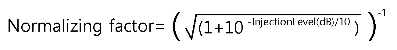
이 때, 파워 노멀라이저(345)는 하기 수학식 2의 노멀라이징 팩터(normalizing factor)를 결합된 신호의 크기에 곱하여 알맞은 신호의 크기로 조절할 수 있다. 하기 수학식 2를 계산하기 위한 인젝션 레벨 정보는 시그널링 플로우(signaling flow)를 통해 파워 노멀라이저(345)로 전달될 수 있다.
[수학식 2]
Figure PCTKR2016003034-appb-I000002
인핸스드 레이어 신호 SE가 코어 레이어 신호 SC에 기설정된 인젝션 레벨에 의해 인젝션될 때 코어 레이어 신호 및 인핸스드 레이어 신호의 파워 레벨이 1로 노멀라이즈된다고 가정하면, 결합 신호는
Figure PCTKR2016003034-appb-I000003
와 같이 표현될 수 있다.
이 때, α는 다양한 인젝션 레벨들에 상응하는 스케일링 팩터(scaling factor)를 나타낸다. 즉, 인젝션 레벨 컨트롤러(330)는 스케일링 팩터에 상응하는 것일 수 있다.
예를 들어, 인핸스드 레이어의 인젝션 레벨이 3dB이면, 결합된 신호는
Figure PCTKR2016003034-appb-I000004
와 같이 표현될 수 있다.
결합된(combined) 신호(멀티플렉싱된 신호)의 파워가 코어 레이어 신호와 비교하여 증가하였기 때문에, 파워 노멀라이저(345)는 이와 같은 파워 증가를 완화(mitigate)시켜야 한다.
파워 노멀라이저(345)의 출력은
Figure PCTKR2016003034-appb-I000005
와 같이 표현될 수 있다.
이 때, β는 인핸스드 레이어의 다양한 인젝션 레벨에 따른 노멀라이징 팩터(normalizing factor)를 나타낸다.
인핸스드 레이어의 인젝션 레벨이 3dB인 경우, 코어 레이어 신호 대비 결합 신호의 파워 증가는 50%이다. 따라서, 파워 노멀라이저(345)의 출력은
Figure PCTKR2016003034-appb-I000006
와 같이 표현될 수 있다.
하기 표 1은 다양한 인젝션 레벨에 따른 스케일링 팩터 α와 노멀라이징 팩터 β를 나타낸다(CL: Core Layer, EL: Enhanced Layer). 인젝션 레벨과 스케일링 팩터 α및 노멀라이징 팩터 β와의 관계는 아래와 같이 정의될 수 있다.
[수학식 3]
Figure PCTKR2016003034-appb-I000007
EL Injection level relative to CL Scaling factor α Normalizing factor β
3.0 dB 0.7079458 0.8161736
3.5 dB 0.6683439 0.8314061
4.0 dB 0.6309573 0.8457262
4.5 dB 0.5956621 0.8591327
5.0 dB 0.5623413 0.8716346
5.5 dB 0.5308844 0.8832495
6.0 dB 0.5011872 0.8940022
6.5 dB 0.4731513 0.9039241
7.0 dB 0.4466836 0.9130512
7.5 dB 0.4216965 0.9214231
8.0 dB 0.3981072 0.9290819
8.5 dB 0.3758374 0.9360712
9.0 dB 0.3548134 0.9424353
9.5 dB 0.3349654 0.9482180
10.0 dB 0.3162278 0.9534626
즉, 파워 노멀라이저(345)는 노멀라이징 팩터(normalizing factor)에 상응하고, 멀티플렉싱된 신호의 파워를 결합기(340)에 의하여 상승된 만큼 낮추는 것으로 볼 수 있다.
이 때, 노멀라이징 팩터 및 스케일링 팩터는 각각 0보다 크고 1보다 작은 유리수일 수 있다.
이 때, 스케일링 팩터는 인젝션 레벨 컨트롤러(330)에 상응하는 파워 감소가 클수록 감소하고, 노멀라이징 팩터는 인젝션 레벨 컨트롤러(330)에 상응하는 파워 감소가 클수록 증가할 수 있다.
파워 노멀라이징된 신호는 채널에서 발생하는 군집오류(burst error)를 분산시키기 위한 타임 인터리버(time interleaver)(350)를 통과한다.
이 때, 타임 인터리버(350)는 코어 레이어 신호 및 인핸스드 레이어 신호에 함께 적용되는 인터리빙을 수행하는 것으로 볼 수 있다. 즉, 코어 레이어와 인핸스드 레이어가 타임 인터리버를 공유함으로써 불필요한 메모리 사용을 방지하고, 수신기에서의 레이턴시를 줄일 수 있다.
후술하겠지만, 인핸스드 레이어 신호는 코어 레이어 신호에 상응하는 코어 레이어 데이터의 복원에 상응하는 캔슬레이션(cancellation)에 기반하여 복원되는 인핸스드 레이어 데이터에 상응하는 것일 수 있고, 결합기(340)는 코어 레이어 신호 및 인핸스드 레이어 신호보다 낮은 파워 레벨의 하나 이상의 확장 레이어(extension layer) 신호를 상기 코어 레이어 신호 및 인핸스드 레이어 신호와 함께 결합할 수 있다.
한편, 인젝션 레벨 정보를 포함하는 L1 시그널링 정보는 시그널링 전용의 BICM을 포함하는 시그널링 생성부(360)에서 부호화된다. 이 때, 시그널링 생성부(360)는 인젝션 레벨 컨트롤러(330)로부터 인젝션 레벨 정보(IL INFO)를 제공 받아서 L1 시그널링 신호를 생성할 수 있다.
L1 시그널링에서 L1은 ISO 7 레이어 모델의 최하위 레이어(lowest layer)인 레이어 1(Layer-1)을 나타낸다. 이 때, L1 시그널링은 프리앰블(preamble)에 포함될 수도 있다.
일반적으로, L1 시그널링은 OFDM 송신기의 주요 파라미터인 FFT 사이즈, 가드 인터벌 사이즈(guard interval size) 등과 BICM 주요 파라미터인 채널 코드 레이트(channel code rate), 모듈레이션 정보 등을 포함할 수 있다. 이러한 L1 시그널링 신호는 데이터 신호와 결합하여 방송 신호 프레임을 구성한다.
프레임 빌더(370)는 L1 시그널링 신호와 데이터 신호를 결합하여 방송 신호 프레임을 생성한다. 이 때, 프레임 빌더(370)는 타임 인터리빙된 신호를 이용하여 상기 코어 레이어 신호와 상기 인핸스드 레이어 신호에 공유되는 타임 인터리버 정보 및 피지컬 레이어 파이프들(Physical Layer Pipes; PLPs)의 사이즈 정보를 시그널링하기 위한 프리앰블을 포함하는 방송 신호 프레임을 생성할 수 있다. 이 때, 방송 신호 프레임은 부트스트랩을 더 포함할 수 있다.
이 때, 프레임 빌더(370)는 타임 인터리버(350)에 상응하는 타임 인터리버 정보를 시그널링하기 위한 프리앰블을 포함하는 방송 신호 프레임을 생성하는 것으로 볼 수 있다.
이 때, 타임 인터리버(350)는 타임 인터리버 그룹들 중 하나를 이용하고, 상기 타임 인터리버 그룹들 사이의 경계(boundary)는 상기 코어 레이어 신호에 상응하는 코어 레이어의 피지컬 레이어 파이프들(Physical Layer Pipes; PLPs) 사이의 경계일 수 있다. 즉, 코어 레이어의 피지컬 레이어 파이프들 사이의 경계들 중 하나가 타임 인터리버 그룹들 사이의 경계가 될 수 있다.
이 때, 타임 인터리버 정보는 상기 코어 레이어를 기준으로 시그널링될 수 있다.
실시예에 따라 타임 인터리버 정보 중 일부는 코어 레이어를 기준으로 시그널링되고, 타임 인터리버 정보 중 다른 일부는 레이어와 무관하게 시그널링될 수 있다.
즉, 타임 인터리버 정보는 코어 레이어에 상응하는 레이어 식별 정보에 기반하여 시그널링될 수 있다.
이 때, 타임 인터리버(350)는 하이브리드 타임 인터리버(hybrid time interleaver)에 상응하는 것일 수 있다.
이 때, 타임 인터리버 그룹들은 온전한 FEC 블로들만(only complete FEC blocks)을 포함하는 피지컬 레이어 파이프들(Physical Layer Pipes; PLPs)만을 포함할 수 있다.
이 때, 프리앰블은 상기 타임 인터리버 그룹들의 경계가 상기 인핸스드 레이어의 FEC 블록들의 경계에 상응하지 않는 경우, 상기 타임 인터리버 그룹들의 경계에 상응하는 상기 인핸스드 레이어의 FEC 블록의 일부분을 식별하기 위한 정보를 시그널링할 수 있다.
이 때, FEC 블록의 일부분을 식별하기 위한 정보는 상기 코어 레이어의 피지컬 레이어 파이프의 시작 위치 정보, 상기 인핸스드 레이어의 피지컬 레이어 파이프의 시작 위치 정보, 상기 인핸스드 레이어에 상응하는 모듈레이션 정보 및 상기 인핸스드 레이어에 상응하는 FEC 타입 정보 중 어느 하나 이상을 포함할 수 있다.
이 때, 피지컬 레이어 파이프의 시작 위치 정보는 상기 피지컬 레이어 파이프의 첫 번째 데이터 셀의 인덱스에 상응하는 것일 수 있다.
이 때, 모듈레이션 정보는 상기 FEC 타입 정보가 기설정된 조건을 만족하는 경우에만 시그널링될 수 있다.
이 때, 인핸스드 레이어 신호는 상기 코어 레이어 신호에 상응하는 코어 레이어 데이터의 복원에 상응하는 캔슬레이션(cancellation)에 기반하여 복원되는 인핸스드 레이어 데이터에 상응하는 것일 수 있다.
이 때, 타임 인터리버(350)는 컨벌루셔널 타임 인터리버(convolutional time interleaver)에 상응하고, 상기 타임 인터리버 그룹들은 완전하지 않은 FEC 블록(incomplete FEC block)을 포함하는 피지컬 레이어 파이프(Physical Layer Pipe; PLP)을 포함하고, 상기 프리앰블은 상기 피지컬 레이어 파이프 내의 첫 번째 완전한 FEC 블록의 시작 위치 정보를 시그널링할 수 있다.
이 때, 프레임 빌더(370)는 상기 부트스트랩을 생성하는 부트스트랩 생성부; 상기 프리앰블을 생성하는 프리앰블 생성부; 및 상기 타임 인터리빙된 신호에 상응하는 수퍼 임포우즈드 페이로드를 생성하는 수퍼 임포우즈드 페이로드 생성부를 포함할 수 있다.
이 때, 부트스트랩은 상기 프리앰블보다 짧고, 고정된 길이를 가질 수 있다.
이 때, 부트스트랩은 상기 프리앰블의 구조를 나타내는 심볼을 포함하고,
상기 심볼은 상기 프리앰블의 변조방법/부호율, FFT 사이즈, 가드 인터벌 길이 및 파일럿 패턴의 조합을 나타내는 고정(fixed-length) 비트열(bit string)에 상응하는 것일 수 있다.
이 때, 심볼은 상기 변조방법/부호율이 동일한 경우, 제1 FFT 사이즈에 상응하는 프리앰블 구조보다, 상기 제1 FFT 사이즈보다 작은 제2 FFT 사이즈에 상응하는 프리앰블 구조가 우선적으로 할당되고, 상기 변조방법/부호율 및 상기 FFT 사이즈가 동일한 경우, 제1 가드 인터벌 길이에 상응하는 프리앰블 구조보다, 상기 제1 가드 인터벌 길이보다 큰 제2 가드 인터벌 길이에 상응하는 프리앰블 구조가 우선적으로 할당되는 룩업 테이블에 상응하는 것일 수 있다.
방송 신호 프레임은 멀티패스(multi-path) 및 도플러(Doppler)에 강인한 OFDM 송신기를 거쳐서 전송된다. 이 때, OFDM 송신기는 차세대 방송시스템의 전송신호 생성을 담당하는 것으로 볼 수 있다.
이 때, 프리앰블은 피지컬 레이어 파이프들(Physical Layer Pipes; PLPs)을 식별하기 위한 PLP 식별 정보; 및 계층적인 분할에 상응하는 레이어들을 식별하기 위한 레이어 식별 정보를 포함할 수 있다.
이 때, PLP 식별 정보 및 레이어 식별 정보는 별개의 필드들로 상기 프리앰블에 포함될 수 있다.
이 때, 타임 인터리버 정보는 코어 레이어를 기준으로 상기 프리앰블에 포함될 수 있다.
이 때, 프리앰블은 상기 피지컬 레이어 파이프들 각각에 대하여 상기 레이어 식별 정보와 기설정된 값을 비교(IF(j>0))한 결과에 따라 선택적으로 상기 인젝션 레벨 컨트롤러에 상응하는 인젝션 레벨 정보를 포함할 수 있다.
이 때, 프리앰블은 피지컬 레이어 파이프들의 타입 정보, 시작 위치 정보 및 사이즈 정보를 포함할 수 있다.
이 때, 타입 정보는 분산되지 않은(non-dispersed) 피지컬 레이어 파이프에 상응하는 제1 타입과 분산된(dispersed) 피지컬 레이어 파이프에 상응하는 제2 타입 중 어느 하나를 식별하기 위한 것일 수 있다.
이 때, 분산되지 않은 피지컬 레이어 파이프는 연속적인 데이터 셀 인덱스들(contiguous data cell indices)에 대하여 할당되고, 상기 분산된 피지컬 레이어 파이프는 둘 이상의 서브슬라이스들로 이루어질 수 있다.
이 때, 타입 정보는 상기 피지컬 레이어 파이프들 각각에 대하여 상기 레이어 식별 정보와 기설정된 값을 비교한 결과에 따라 선택적으로 시그널링될 수 있다.
이 때, 타입 정보는 코어 레이어에 대해서만 시그널링될 수 있다.
이 때, 시작 위치 정보는 피지컬 레이어 파이프의 첫 번째 데이터 셀에 상응하는 인덱스와 동일하게 설정될 수 있다.
이 때, 시작 위치 정보는 셀 어드레싱 스킴(cell addressing scheme)을 이용하여 상기 피지컬 레이어 파이프의 시작 위치(start position)를 지시(indicate)할 수 있다.
이 때, 시작 위치 정보는 상기 레이어 식별 정보에 상응하는 조건문의 조건 판단 없이 상기 피지컬 레이어 파이프들 각각에 대하여 상기 프리앰블에 포함될 수 있다.
이 때, 사이즈 정보는 상기 피지컬 레이어 파이프에 할당된 데이터 셀들의 개수에 기반하여 설정될 수 있다.
이 때, 사이즈 정보는 상기 레이어 식별 정보에 상응하는 조건문의 조건 판단 없이 상기 피지컬 레이어 파이프들 각각에 대하여 상기 프리앰블에 포함될 수 있다.
도 4는 방송 신호 프레임 구조의 일 예를 나타낸 도면이다.
도 4를 참조하면, 방송 신호 프레임은 부트스트랩(410), 프리앰블(420) 및 수퍼-임포우스드 페이로드(super-imposed payload)(430)를 포함한다.
도 4에 도시된 프레임은 수퍼프레임(super-frame)에 포함될 수 있다.
이 때, 방송 신호 프레임은 하나 이상의 OFDM 심볼들로 구성될 수 있다. 방송 신호 프레임은 레퍼런스 심볼 또는 파일럿 심볼을 포함할 수도 있다.
LDM(Layered Division Multiplexing)이 적용된 프레임 구조는 도 4에 도시된 바와 같이 부트스트랩(410) 및 프리앰블(420) 및 수퍼-임포우스드 페이로드(430)를 포함한다.
이 때, 부트스트랩(410) 및 프리앰블(420)은 두 개의 프리앰블들이 계층화된(hierarchical) 것으로 볼 수 있다.
이 때, 부트스트랩(410)은 빠른(fast) 획득(acquisition) 및 검출(detection)을 위해 프리앰블(420)보다 짧은 길이를 가질 수 있다. 이 때, 부트스트랩(410)은 고정된 길이를 가질 수 있다. 이 때, 부트스트랩(410)은 고정된 길이의 심볼을 포함할 수 있다. 예를 들어, 부트스트랩(410)은 각각 0.5ms 길이의 OFDM 심볼들 4개로 구성되어 총 2ms의 고정된 시간길이를 가질 수 있다.
이 때, 부트스트랩(410)은 고정된 대역폭(bandwidth)을 가지고, 프리앰블(420) 및 수퍼-임포우스드 페이로드(430)는 부트스트랩(410)보다 넓고 가변적인 대역폭을 가질 수 있다.
프리앰블(420)은 강인(robust)한 LDPC 코드를 사용하여 상세한 시그널링 정보를 전송할 수 있다. 이 때, 프리앰블(420)은 시그널링 정보에 따라 길이가 가변될 수 있다.
이 때, 부트스트랩(410) 및 페이로드(430)는 모두 여러 레이어들이 공유하는 공통 신호에 상응하는 것으로 볼 수 있다.
수퍼-임포우스드 페이로드(430)는 두 개 이상의 계층(layer) 신호들이 멀티플렉싱된 신호에 상응하는 것일 수 있다. 이 때, 수퍼-임포우스드 페이로드(430)는 코어 레이어 페이로드 및 인핸스드 레이어 페이로드가 서로 다른 파워 레벨로 결합된 것일 수 있다. 이 때, 코어 레이어 페이로드에는 인-밴드 시그널링부(in-band signaling section)가 포함될 수 있다. 이 때, 인-밴드 시그널링부는 인핸스드 레이어 서비스를 위한 시그널링 정보를 포함할 수 있다.
이 때, 부트스트랩(410)은 프리앰블의 구조(preamble structure)를 나타내는 심볼을 포함할 수 있다.
이 때, 프리앰블의 구조를 나타내기 위해 부트스트랩에 포함되는 심볼은 하기 표 2와 같이 설정될 수 있다.
preamble_structure L1-Basic Mode FFT Size GI Length (samples) Pilot Pattern (DX)
0 L1-Basic Mode 1 8192 2048 3
1 L1-Basic Mode 1 8192 1536 4
2 L1-Basic Mode 1 8192 1024 3
3 L1-Basic Mode 1 8192 768 4
4 L1-Basic Mode 1 16384 4096 3
5 L1-Basic Mode 1 16384 3648 4
6 L1-Basic Mode 1 16384 2432 3
7 L1-Basic Mode 1 16384 1536 4
8 L1-Basic Mode 1 16384 1024 6
9 L1-Basic Mode 1 16384 768 8
10 L1-Basic Mode 1 32768 4864 3
11 L1-Basic Mode 1 32768 3648 3
12 L1-Basic Mode 1 32768 3648 8
13 L1-Basic Mode 1 32768 2432 6
14 L1-Basic Mode 1 32768 1536 8
15 L1-Basic Mode 1 32768 1024 12
16 L1-Basic Mode 1 32768 768 16
17 L1-Basic Mode 2 8192 2048 3
18 L1-Basic Mode 2 8192 1536 4
19 L1-Basic Mode 2 8192 1024 3
20 L1-Basic Mode 2 8192 768 4
21 L1-Basic Mode 2 16384 4096 3
22 L1-Basic Mode 2 16384 3648 4
23 L1-Basic Mode 2 16384 2432 3
24 L1-Basic Mode 2 16384 1536 4
25 L1-Basic Mode 2 16384 1024 6
26 L1-Basic Mode 2 16384 768 8
27 L1-Basic Mode 2 32768 4864 3
28 L1-Basic Mode 2 32768 3648 3
29 L1-Basic Mode 2 32768 3648 8
30 L1-Basic Mode 2 32768 2432 6
31 L1-Basic Mode 2 32768 1536 8
32 L1-Basic Mode 2 32768 1024 12
33 L1-Basic Mode 2 32768 768 16
34 L1-Basic Mode 3 8192 2048 3
35 L1-Basic Mode 3 8192 1536 4
36 L1-Basic Mode 3 8192 1024 3
37 L1-Basic Mode 3 8192 768 4
38 L1-Basic Mode 3 16384 4096 3
39 L1-Basic Mode 3 16384 3648 4
40 L1-Basic Mode 3 16384 2432 3
41 L1-Basic Mode 3 16384 1536 4
42 L1-Basic Mode 3 16384 1024 6
43 L1-Basic Mode 3 16384 768 8
44 L1-Basic Mode 3 32768 4864 3
45 L1-Basic Mode 3 32768 3648 3
46 L1-Basic Mode 3 32768 3648 8
47 L1-Basic Mode 3 32768 2432 6
48 L1-Basic Mode 3 32768 1536 8
49 L1-Basic Mode 3 32768 1024 12
50 L1-Basic Mode 3 32768 768 16
51 L1-Basic Mode 4 8192 2048 3
52 L1-Basic Mode 4 8192 1536 4
53 L1-Basic Mode 4 8192 1024 3
54 L1-Basic Mode 4 8192 768 4
55 L1-Basic Mode 4 16384 4096 3
56 L1-Basic Mode 4 16384 3648 4
57 L1-Basic Mode 4 16384 2432 3
58 L1-Basic Mode 4 16384 1536 4
59 L1-Basic Mode 4 16384 1024 6
60 L1-Basic Mode 4 16384 768 8
61 L1-Basic Mode 4 32768 4864 3
62 L1-Basic Mode 4 32768 3648 3
63 L1-Basic Mode 4 32768 3648 8
64 L1-Basic Mode 4 32768 2432 6
65 L1-Basic Mode 4 32768 1536 8
66 L1-Basic Mode 4 32768 1024 12
67 L1-Basic Mode 4 32768 768 16
68 L1-Basic Mode 5 8192 2048 3
69 L1-Basic Mode 5 8192 1536 4
70 L1-Basic Mode 5 8192 1024 3
71 L1-Basic Mode 5 8192 768 4
72 L1-Basic Mode 5 16384 4096 3
73 L1-Basic Mode 5 16384 3648 4
74 L1-Basic Mode 5 16384 2432 3
75 L1-Basic Mode 5 16384 1536 4
76 L1-Basic Mode 5 16384 1024 6
77 L1-Basic Mode 5 16384 768 8
78 L1-Basic Mode 5 32768 4864 3
79 L1-Basic Mode 5 32768 3648 3
80 L1-Basic Mode 5 32768 3648 8
81 L1-Basic Mode 5 32768 2432 6
82 L1-Basic Mode 5 32768 1536 8
83 L1-Basic Mode 5 32768 1024 12
84 L1-Basic Mode 5 32768 768 16
85 L1-Basic Mode 6 8192 2048 3
86 L1-Basic Mode 6 8192 1536 4
87 L1-Basic Mode 6 8192 1024 3
88 L1-Basic Mode 6 8192 768 4
89 L1-Basic Mode 6 16384 4096 3
90 L1-Basic Mode 6 16384 3648 4
91 L1-Basic Mode 6 16384 2432 3
92 L1-Basic Mode 6 16384 1536 4
93 L1-Basic Mode 6 16384 1024 6
94 L1-Basic Mode 6 16384 768 8
95 L1-Basic Mode 6 32768 4864 3
96 L1-Basic Mode 6 32768 3648 3
97 L1-Basic Mode 6 32768 3648 8
98 L1-Basic Mode 6 32768 2432 6
99 L1-Basic Mode 6 32768 1536 8
100 L1-Basic Mode 6 32768 1024 12
101 L1-Basic Mode 6 32768 768 16
102 L1-Basic Mode 7 8192 2048 3
103 L1-Basic Mode 7 8192 1536 4
104 L1-Basic Mode 7 8192 1024 3
105 L1-Basic Mode 7 8192 768 4
106 L1-Basic Mode 7 16384 4096 3
107 L1-Basic Mode 7 16384 3648 4
108 L1-Basic Mode 7 16384 2432 3
109 L1-Basic Mode 7 16384 1536 4
110 L1-Basic Mode 7 16384 1024 6
111 L1-Basic Mode 7 16384 768 8
112 L1-Basic Mode 7 32768 4864 3
113 L1-Basic Mode 7 32768 3648 3
114 L1-Basic Mode 7 32768 3648 8
115 L1-Basic Mode 7 32768 2432 6
116 L1-Basic Mode 7 32768 1536 8
117 L1-Basic Mode 7 32768 1024 12
118 L1-Basic Mode 7 32768 768 16
119 Reserved Reserved Reserved Reserved
120 Reserved Reserved Reserved Reserved
121 Reserved Reserved Reserved Reserved
122 Reserved Reserved Reserved Reserved
123 Reserved Reserved Reserved Reserved
124 Reserved Reserved Reserved Reserved
125 Reserved Reserved Reserved Reserved
126 Reserved Reserved Reserved Reserved
127 Reserved Reserved Reserved Reserved
예를 들어, 상기 표 2에 표시된 프리앰블 구조를 나타내기 위해, 7비트의 고정된 심볼이 할당될 수 있다.
상기 표 2에 기재된 L1-Basic Mode 1, L1-Basic Mode 2 및 L1-Basic Mode 3은 QPSK 및 3/15 LDPC에 상응하는 것일 수 있다.
상기 표 2에 기재된 L1-Basic Mode 4는 16-NUC(Non Uniform Constellation) 및 3/15 LDPC에 상응하는 것일 수 있다.
상기 표 2에 기재된 L1-Basic Mode 5는 64-NUC(Non Uniform Constellation) 및 3/15 LDPC에 상응하는 것일 수 있다.
상기 표 2에 기재된 L1-Basic Mode 6 및 L1-Basic Mode 7은 256-NUC(Non Uniform Constellation) 및 3/15 LDPC에 상응하는 것일 수 있다. 이하에서 설명하는 변조방법/부호율은 QPSK 및 3/15 LDPC와 같이 변조방법과 부호율의 조합을 나타낸다.
상기 표 2에 기재된 FFT size는 Fast Fourier Transform 크기를 나타내는 것일 수 있다.
상기 표 2에 기재된 GI length는 가드 인터벌 길이(Guard Interval Length)를 나타내는 것으로, 시간 영역에서 데이터가 아닌 가드 인터벌의 길이를 나타내는 것일 수 있다. 이 때, 가드 인터벌 길이가 길수록 시스템은 강인(robust)해진다.
상기 표 2에 기재된 Pilot Pattern은 파일럿 패턴의 Dx를 나타내는 것일 수 있다. 표 2에는 명시적으로 기재하지 않았으나 표 2에 기재된 예에서 Dy는 모두 1일 수 있다. 예를 들어, Dx = 3은 채널 추정을 위한 파일럿이 x축 방향으로 3개 중 하나 포함됨을 의미할 수 있다. 예를 들어, Dy = 1은 y축 방향으로 매 번 파일럿이 포함됨을 의미할 수 있다.
표 2의 예에서 알 수 있는 바와 같이, 제1 변조방법/부호율보다 강인한 제2 변조방법/부호율에 상응하는 프리앰블 구조가 상기 제1 변조방법/부호율에 상응하는 프리앰블 구조보다 우선적으로 룩업테이블에 할당될 수 있다.
이 때, 우선적으로 할당된다 함은 룩업테이블에 보다 작은 수의 인덱스에 상응하여 저장되는 것일 수 있다.
또한, 같은 변조방법/부호율의 경우 제1 FFT 사이즈보다 작은 제2 FFT 사이즈에 상응하는 프리앰블 구조가 상기 제1 FFT 사이즈에 상응하는 프리앰블 구조보다 우선적으로 룩업테이블에 할당될 수 있다.
또한, 같은 변조방법/부호율 및 FFT 사이즈의 경우 제1 가드 인터벌보다 큰 제2 가드 인터벌에 상응하는 프리앰블 구조가 상기 제1 가드 인터벌에 상응하는 프리앰블 구조보다 우선적으로 룩업테이블에 할당될 수 있다.
표 2에 기재된 바와 같이 룩업테이블에 프리앰블 구조가 할당되는 순서를 설정함으로써 부트스트랩을 이용한 프리앰블 구조 식별이 보다 효율적으로 수행될 수 있다.
도 5는 도 4에 도시된 방송 신호 프레임이 수신되는 과정의 일 예를 나타낸 도면이다.
도 5를 참조하면, 부트스트랩(510)이 검출되어 복조되고, 복조된 정보를 이용하여 프리앰블(520)이 복조되어 시그널링 정보가 복원된다.
시그널링 정보를 이용하여 코어 레이어 데이터(530)가 복조되고, 코어 레이어 데이터에 상응하는 캔슬레이션 과정을 거쳐서 인핸스드 레이어 신호가 복조된다. 이 때, 코어 레이어 데이터에 상응하는 캔슬레이션에 대해서는 이후 보다 상세히 설명한다.
도 6은 도 4에 도시된 방송 신호 프레임이 수신되는 과정의 다른 예를 나타낸 도면이다.
도 6을 참조하면, 부트스트랩(610)이 검출되어 복조되고, 복조된 정보를 이용하여 프리앰블(620)이 복조되어 시그널링 정보가 복원된다.
시그널링 정보를 이용하여 코어 레이어 데이터(630)가 복조된다. 이 때, 코어 레이어 데이터(630)에는 인-밴드 시그널링부(650)가 포함된다. 인-밴드 시그널링부(650)는 인핸스드 레이어 서비스를 위한 시그널링 정보를 포함한다. 인-밴드 시그널링부(650)를 통해, 보다 효율적인 대역폭(bandwidth) 활용이 가능하다. 이 때, 인-밴드 시그널링부(650)는 인핸스드 레이어보다 강인한 코어 레이어에 포함되는 것이 바람직하다.
도 6에 도시된 예에서, 프리앰블(620)을 통해 기본적인 시그널링 정보 및 코어 레이어 서비스를 위한 정보가 전달되고, 인-밴드 시그널링부(650)를 통해 인핸드스 레이어 서비스를 위한 시그널링 정보가 전달될 수 있다.
코어 레이어 데이터에 상응하는 캔슬레이션 과정을 거쳐서 인핸스드 레이어 신호가 복조된다.
이 때, 시그널링 정보는 L1(Layer-1) 시그널링 정보일 수 있다. L1 시그널링 정보는 물리 계층 파라미터들을 구성하기 위해 필요한 정보를 포함할 수 있다.
도 4를 참조하면, 방송 신호 프레임은 L1 시그널링 신호 및 데이터 신호를 포함한다. 예를 들어, 방송 신호 프레임은 ATSC 3.0 프레임일 수 있다.
도 7는 도 1에 도시된 방송 신호 프레임 생성 장치의 다른 예를 나타낸 블록도이다.
도 7를 참조하면, 방송 신호 프레임 생성 장치가 코어 레이어 데이터 및 인핸스드 레이어 데이터 이외에도 N개(N은 1이상의 자연수)의 확장 레이어들(Extension Layers)에 상응하는 데이터를 함께 멀티플렉싱하는 것을 알 수 있다.
즉, 도 7에 도시된 방송 신호 프레임 생성 장치는 코어 레이어 BICM부(310), 인핸스드 레이어 BICM부(320), 인젝션 레벨 컨트롤러(330), 결합기(340), 파워 노멀라이저(345), 타임 인터리버(350), 시그널링 생성부(360) 및 프레임 빌더(370) 이외에도 N개의 확장 레이어 BICM부들(410, ..., 430) 및 인젝션 레벨 컨트롤러들(440, ..., 460)을 포함한다.
도 7에 도시된 코어 레이어 BICM부(310), 인핸스드 레이어 BICM부(320), 인젝션 레벨 컨트롤러(330), 결합기(340), 파워 노멀라이저(345), 타임 인터리버(350), 시그널링 생성부(360) 및 프레임 빌더(370)에 대해서는 도 3을 통하여 이미 상세히 설명한 바 있다.
N개의 확장 레이어 BICM부들(410, ..., 430)은 각각 독립적으로 BICM 인코딩을 수행하고, 인젝션 레벨 컨트롤러들(440, ..., 460)은 각각의 확장 레이어에 상응하는 파워 리듀싱을 수행하여 파워 리듀싱된 확장 레이어 신호가 결합기(340)를 통해 다른 레이어 신호들과 결합되도록 한다.
이 때, 확장 레이어 BICM부들(410, ..., 430) 각각의 오류정정 부호화기는 BCH 인코더와 LDPC 인코더가 직렬연결된 것일 수 있다.
특히, 인젝션 레벨 컨트롤러들(440, ..., 460) 각각에 상응하는 파워 감소는 인젝션 레벨 컨트롤러(330)의 파워 감소보다 큰 것이 바람직하다. 즉, 도 7에 도시된 인젝션 레벨 컨트롤러들(330, 440, ..., 460)은 아래로 내려올수록 큰 파워 감소에 상응할 수 있다.
도 7에 도시된 인젝션 레벨 컨트롤러들(330, 440, 460)로부터 제공된 인젝션 레벨 정보는 시그널링 생성부(360)를 거쳐서 프레임 빌더(370)의 방송 신호 프레임에 포함되어 수신기로 전송된다. 즉, 각 계층의 인젝션 레벨은 L1 시그널링 정보에 담겨, 수신기로 전달된다.
본 발명에서 파워 조절은 입력 신호의 파워를 증가 또는 감소시키는 것일 수도 있고, 입력 신호의 게인을 증가 또는 감소시키는 것일 수도 있다.
파워 노멀라이저(345)는 결합기(340)에 의하여 복수의 레이어 신호들이 결합됨으로써 야기되는 파워 증가를 완화(mitigate)시킨다.
도 7에 도시된 예에서, 파워 노멀라이저(345)는 하기 수학식 4를 이용하여 노멀라이징 팩터를 각 계층(layer)들의 신호가 결합된 신호의 크기에 곱하여 알맞은 신호 크기로 신호 파워를 조절할 수 있다.
[수학식 4]
Normalizing Factor =
Figure PCTKR2016003034-appb-I000008
타임 인터리버(350)는 결합기(340)에 의하여 결합된 신호에 대한 인터리빙을 수행함으로써, 레이어들의 신호들에 함께 적용되는 인터리빙을 수행한다.
도 8은 도 1에 도시된 신호 디멀티플렉싱 장치의 일 예를 나타낸 블록도이다.
도 8를 참조하면, 본 발명의 일실시예에 따른 신호 디멀티플렉싱 장치는 타임 디인터리버(510), 디-노멀라이저(1010), 코어 레이어 BICM 디코더(520), 인핸스드 레이어 심볼 추출기(530), 디-인젝션 레벨 컨트롤러(1020) 및 인핸스드 레이어 BICM 디코더(540)를 포함한다.
이 때, 도 8에 도시된 신호 디멀티플렉싱 장치는 도 3에 도시된 방송 신호 프레임 생성 장치에 상응하는 것일 수 있다.
타임 디인터리버(510)는 시간/주파수 동기(synchronization), 채널추정(channel estimation) 및 등화(equalization) 등의 동작을 수행하는 OFDM 수신기로부터 수신 신호를 제공 받고, 채널에서 발생한 군집오류(burst error) 분산에 관한 동작을 수행한다. 이 때, L1 시그널링 정보는 OFDM 수신기에서 우선적으로 복호되어, 데이터 복호에 활용될 수 있다. 특히, L1 시그널링 정보 중 인젝션 레벨 정보는 디-노멀라이저(1010)와 디-인젝션 레벨 컨트롤러(1020)에 전달될 수 있다. 이 때, OFDM 수신기는 수신 신호를 방송 신호 프레임(예를 들어, ATSC 3.0 프레임)의 형태로 복호화한 후, 프레임의 데이터 심볼 부분을 추출하여 타임 디인터리버(510)로 제공할 수 있다. 즉, 타임 디인터리버(510)는 데이터 심볼을 통과시키면서 역인터리빙 과정을 수행하여 채널에서 발생한 군집오류를 분산시킨다.
디-노멀라이저(1010)는 송신기의 파워 노멀라이저에 상응하는 것으로, 파워 노멀라이저에서 감소시킨 만큼 파워를 높인다. 즉, 디-노멀라이저(1010)는 수신 신호를 상기 수학식 2의 노멀라이징 팩터로 나눈다.
도 8에 도시된 예에서, 디-노멀라이저(1010)는 타임 인터리버(510)의 출력 신호의 파워를 조절하는 것으로 도시되었으나, 실시예에 따라 디-노멀라이저(1010)는 타임 인터리버(510)의 앞에 위치하여 인터리빙 되기 전에 파워 조절이 수행되도록 할 수도 있다.
즉, 디-노멀라이저(1010)는 타임 인터리버(510)의 앞 또는 뒤에 위치하여 코어 레이어 심볼 디맵퍼의 LLR 계산 등을 위해 신호의 크기를 증폭하는 것으로 볼 수 있다.
타임 디인터리버(510)의 출력(또는 디-노멀라이저(1010)의 출력)은 코어 레이어 BICM 디코더(520)로 제공되고, 코어 레이어 BICM 디코더(520)는 코어 레이어 데이터를 복원한다.
이 때, 코어 레이어 BICM 디코더(520)는 코어 레이어 심볼 디맵퍼, 코어 레이어 비트 디인터리버 및 코어 레이어 오류정정 복호화기를 포함한다. 코어 레이어 심볼 디맵퍼는 심볼과 관련된 LLR(Log-Likelihood Ratio) 값들을 계산하고, 코어 레이어 비트 디인터리버는 계산된 LLR 값들을 군집오류에 강하게 섞으며, 코어 레이어 오류정정 복호화기는 채널에서 발생한 오류를 정정한다.
이 때, 코어 레이어 심볼 디맵퍼는 미리 결정된 성상도를 이용하여 비트별로 LLR 값을 계산할 수 있다. 이 때 코어 레이어 심볼 맵퍼에서 이용하는 성상도는 송신기에서 사용되는 코드 레이트와 모듈레이션 차수(modulation order)의 조합에 따라 상이할 수 있다.
이 때, 코어 레이어 비트 디인터리버는 계산된 LLR 값들에 대하여 LDPC 코드워드 단위로 역인터리빙을 수행할 수 있다.
특히, 코어 레이어 오류정정 복호화기는 정보(information) 비트들만을 출력할 수도 있고, 정보 비트들과 패러티 비트들이 결합된 전체 비트들을 출력할 수도 있다. 이 때, 코어 레이어 오류정정 복호화기는 정보 비트들만을 코어 레이어 데이터로 출력하고, 정보 비트들에 패러티 비트들이 결합된 전체 비트들을 인핸스드 레이어 심볼 추출기(530)로 출력할 수 있다.
코어 레이어 오류 정정 복호화기는 코어 레이어 LDPC 복호화기와 코어 레이어 BCH 복호화기가 직렬 연결된 형태일 수 있다. 즉, 코어 레이어 오류 정정 복호화기의 입력이 코어 레이어 LDPC 복호화기로 입력되고, 코어 레이어 LDPC 복호화기의 출력이 코어 레이어 BCH 복호화기로 입력되고, 코어 레이어 BCH 복호화기의 출력이 코어 레이어 오류 정정 복호화기의 출력이 될 수 있다. 이 때, LDPC 복호화기는 LDPC 복호룰 수행하고, BCH 복호화기는 BCH 복호를 수행한다.
나아가, 인핸스드 레이어 오류 정정 복호화기도 인핸스드 레이어 LDPC 복호화기와 인핸스드 레이어 BCH 복호화기가 직렬 연결된 형태일 수 있다. 즉, 인핸스드 레이어 오류 정정 복호화기의 입력이 인핸스드 레이어 LDPC 복호화기로 입력되고, 인핸스드 레이어 LDPC 복호화기의 출력이 인핸스드 레이어 BCH 복호화기로 입력되고, 인핸스드 레이어 BCH 복호화기의 출력이 인핸스드 레이어 오류정정 복호화기의 출력이 될 수 있다.
인핸스드 레이어 심볼 추출기(530)는 코어 레이어 BICM 디코더(520)의 코어 레이어 오류정정 복호화기로부터 전체 비트들을 제공 받아서 타임 디인터리버(510) 또는 디-노멀라이저(1010)의 출력 신호로부터 인핸스드 레이어 심볼들을 추출할 수 있다. 실시예에 따라 인핸스드 레이어 심볼 추출기(530)는 코어 레이어 BICM 디코더(520)의 오류정정 복호화기로부터 전체 비트들을 제공 받지 않고, LDPC의 정보비트들(information bits)을 제공 받거나, BCH 정보 비트들을 제공 받을 수 있다.
이 때, 인핸스드 레이어 심볼 추출기(530)는 버퍼, 감산기(subtracter), 코어 레이어 심볼 맵퍼 및 코어 레이어 비트 인터리버를 포함한다. 버퍼는 타임 디인터리버(510) 또는 디-노멀라이저(1010)의 출력 신호를 저장한다. 코어 레이어 비트 인터리버는 코어 레이어 BICM 디코더의 전체 비트들(정보 비트들+패러티 비트들)을 입력 받아 송신기와 동일한 코어 레이어 비트 인터리빙을 수행한다. 코어 레이어 심볼 맵퍼는 인터리빙된 신호로부터 송신기와 동일한 코어 레이어 심볼을 생성한다. 감산기는 버퍼에 저장된 신호에서 코어 레이어 심볼 맵퍼의 출력 신호를 감산함으로써, 인핸스드 레이어 심볼을 획득하고 이를 디-인젝션 레벨 컨트롤러(1020)에 전달한다. 특히, LDPC 정보비트들을 제공 받는 경우 인핸스드 레이어 심볼 추출기(530)는 코어 레이어 LDPC 인코더를 더 포함할 수 있다. 또한, BCH 정보 비트들을 제공 받는 경우 인핸스드 레이어 심볼 추출기(530)는 코어 레이어 LDPC 인코더뿐만 아니라 코어 레이어 BCH 인코더를 더 포함할 수 있다.
이 때, 인핸스드 레이어 심볼 추출기(530)에 포함되는 코어 레이어 LDPC 인코더, 코어 레이어 BCH 인코더, 코어 레이어 비트 인터리버 및 코어 레이어 심볼 맵퍼는 도 3을 통하여 설명한 코어 레이어의 LDPC 인코더, BCH 인코더, 비트 인터리버 및 심볼 맵퍼와 동일한 것일 수 있다.
디-인젝션 레벨 컨트롤러(1020)는 인핸스드 레이어 심볼을 입력 받아서 송신기의 인젝션 레벨 컨트롤러에 의하여 떨어진 파워만큼 파워를 증가시킨다. 즉, 디-인젝션 레벨 컨트롤러(1020)는 입력 신호를 증폭하여 인핸스드 레이어 BICM 디코더(540)로 제공한다. 예를 들어, 송신기에서 인핸스드 레이어 신호의 파워를 코어 레이어 신호의 파워보다 3dB 작게 결합하였다면, 디-인젝션 레벨 컨트롤러(1020)는 입력 신호의 파워를 3dB 증가시키는 역할을 한다.
이 때, 디-인젝션 레벨 컨트롤러(1020)는 OFDM 수신기로부터 인젝션 레벨 정보를 받아서 추출된 인핸스드 레이어 신호에 하기 수학식 5의 인핸스드 레이어 게인을 곱하는 것으로 볼 수 있다.
[수학식 5]
Enhanced Layer Gain =
Figure PCTKR2016003034-appb-I000009
인핸스드 레이어 BICM 디코더(540)는 디-인젝션 레벨 컨트롤러(1020)에 의하여 파워가 상승된 인핸스드 레이어 심볼을 입력 받아서 인핸스드 레이어 데이터를 복원한다.
이 때, 인핸스드 레이어 BICM 디코더(540)는 인핸스드 레이어 심볼 디맵퍼, 인핸스드 레이어 비트 디인터리버 및 인핸스드 레이어 오류정정 복호화기를 포함할 수 있다. 인핸스드 레이어 심볼 디맵퍼는 인핸스드 레이어 심볼과 관련된 LLR(Log-Likelihood Ratio) 값들을 계산하고, 인핸스드 레이어 비트 디인터리버는 계산된 LLR 값들을 군집오류에 강하게 섞으며, 인핸스드 레이어 오류정정 복호화기는 채널에서 발생한 오류를 정정한다.
인핸스드 레이어 BICM 디코더(540)는 코어 레이어 BICM 디코더(520)와 유사한 작업을 수행하지만, 일반적으로 인핸스드 레이어 LDPC 디코더는 6/15 이상인 코드레이트에 대한 LDPC 복호를 수행한다.
예를 들어, 코어 레이어는 5/15 이하의 코드 레이트를 가지는 LDPC 코드를 사용하고, 인핸스드 레이어는 6/15 이상의 코드 레이트를 가지는 LDPC 코드를 사용할 수 있다. 이 때, 인핸스드 레이어 데이터의 복호가 가능한 수신 환경에서는 코어 레이어 데이터는 적은 수의 LDPC 디코딩 이터레이션(iteration)만으로도 복호가 가능하다. 이러한 성질을 이용하면 수신기 하드웨어는 하나의 LDPC 디코더를 코어 레이어와 인핸스드 레이어가 공유하여 하드웨어 구현시 발생하는 비용을 줄일 수 있다. 이 때, 코어 레이어 LDPC 디코더는 약간의 시간자원(LDPC 디코딩 이터레이션)만을 사용하고 대부분의 시간자원을 인핸스드 레이어 LDPC 디코더가 사용할 수 있다.
도 8에 도시된 신호 디멀티플렉싱 장치는 먼저 코어 레이어 데이터를 복원하고, 수신 신호 심볼에서 코어 레이어 심볼들을 캔슬레이션(cancellation)하여 인핸스드 레이어 심볼들만 남긴 후, 인핸스드 레이어 심볼의 파워를 증가시켜서 인핸스드 레이어 데이터를 복원한다. 도 3 및 5를 통해 이미 설명한 바와 같이, 각각의 레이어에 상응하는 신호들이 서로 다른 파워레벨로 결합되므로 가장 강한 파워로 결합된 신호부터 복원되어야 가장 오류가 적은 데이터 복원이 가능하다.
결국 도 8에 도시된 예에서 신호 디멀티플렉싱 장치는, 수신 신호에 타임 디인터리빙을 적용하여 타임 디인터리빙 신호를 생성하는 타임 디인터리버(510); 상기 수신 신호 또는 상기 타임 디인터리빙 신호의 파워를 송신기의 파워 노멀라이저에 의한 파워 감소만큼 높이는 디-노멀라이저(1010); 상기 디-노멀라이저(1010)에 의해 파워 조절된 신호로부터 코어 레이어 데이터를 복원하는 코어 레이어 BICM 디코더(520); 상기 코어 레이어 BICM 디코더(520)의 코어 레이어 FEC 디코더의 출력 신호를 이용하여, 상기 디-노멀라이저(1010)에 의해 파워 조절된 신호에 대한 상기 코어 레이어 데이터에 상응하는 캔슬레이션을 수행하여 인핸스드 레이어 신호를 추출하는 인핸스드 레이어 심볼 추출기(530); 상기 인핸스드 레이어 신호의 파워를 송신기의 인젝션 레벨 컨트롤러의 파워 감소만큼 높이는 디-인젝션 레벨 컨트롤러(1020); 및 상기 디-인젝션 레벨 컨트롤러(1020)의 출력 신호를 이용하여 인핸스드 레이어 데이터를 복원하는 인핸스드 레이어 BICM 디코더(540)를 포함할 수 있다.
이 때, 인핸스드 레이어 심볼 추출기는 상기 코어 레이어 BICM 디코더의 코어 레이어 LDPC 디코더로부터 전체 코드워드를 입력 받고, 상기 전체 코드워드를 바로 비트 인터리빙할 수 있다.
이 때, 인핸스드 레이어 심볼 추출기는 상기 코어 레이어 BICM 디코더의 코어 레이어 LDPC 디코더로부터 정보 비트들을 입력 받고, 상기 정보 비트들을 코어 레이어 LDPC 인코딩한 후 비트 인터리빙을 수행할 수 있다.
이 때, 인핸스드 레이어 심볼 추출기는 상기 코어 레이어 BICM 디코더의 코어 레이어 BCH 디코더로부터 정보 비트들을 입력 받고, 상기 정보 비트들을 코어 레이어 BCH 인코딩 및 코어 레이어 LDPC 인코딩한 후 비트 인터리빙을 수행할 수 있다.
이 때, 상기 디-노멀라이저 및 상기 디-인젝션 레벨 컨트롤러는 L1 시그널링에 기반하여 제공된 인젝션 레벨 정보(IL INFO)를 제공 받고, 상기 인젝션 레벨 정보에 기반하여 파워 컨트롤을 수행할 수 있다.
이 때, 상기 코어 레이어 BICM 디코더는 상기 인핸스드 레이어 BICM 디코더보다 낮은 비트율을 가지고, 상기 인핸스드 레이어 BICM 디코더보다 강인할(robust) 수 있다.
이 때, 상기 디-노멀라이저는 노멀라이징 팩터의 역수에 상응할 수 있다.
이 때, 상기 디-인젝션 레벨 컨트롤러는 스케일링 팩터의 역수에 상응할 수 있다.
이 때, 인핸스드 레이어 데이터는 코어 레이어 신호에 상응하는 코어 레이어 데이터의 복원에 상응하는 캔슬레이션에 기반하여 복원될 수 있다.
이 때, 신호 디멀티플렉싱 장치는 이전 레이어 데이터에 상응하는 캔슬레이션을 수행하여 확장 레이어 신호를 추출하는 하나 이상의 확장 레이어 심볼 추출기; 상기 확장 레이어 신호의 파워를 송신기의 인젝션 레벨 컨트롤러의 파워 감소만큼 높이는 하나 이상의 디-인젝션 레벨 컨트롤러 및 상기 하나 이상의 디-인젝션 레벨 컨트롤러의 출력 신호를 이용하여 하나 이상의 확장 레이어 데이터를 복원하는 하나 이상의 확장 레이어 BICM 디코더를 더 포함할 수 있다.
도 8에 도시된 구성을 통해 본 발명의 일실시예에 따른 신호 디멀티플렉싱 방법은, 수신 신호에 타임 디인터리빙을 적용하여 타임 디인터리빙 신호를 생성하는 단계; 상기 수신 신호 또는 상기 타임 디인터리빙 신호의 파워를 송신기의 파워 노멀라이저에 의한 파워 감소만큼 높이는 단계; 상기 파워 조절된 신호로부터 코어 레이어 데이터를 복원하는 단계; 상기 파워 조절된 신호에 대한 상기 코어 레이어 데이터에 상응하는 캔슬레이션을 수행하여 인핸스드 레이어 신호를 추출하는 단계; 상기 인핸스드 레이어 신호의 파워를 송신기의 인젝션 레벨 컨트롤러의 파워 감소만큼 높이는 단계; 및 파워 조절된 상기 인핸스드 레이어 신호를 이용하여 인핸스드 레이어 데이터를 복원하는 단계를 포함함을 알 수 있다.
이 때, 인핸스드 레이어 신호를 추출하는 단계는 코어 레이어 BICM 디코더의 코어 레이어 LDPC 디코더로부터 전체 코드워드를 입력 받고, 상기 전체 코드워드를 바로 비트 인터리빙할 수 있다.
이 때, 인핸스드 레이어 신호를 추출하는 단계는 코어 레이어 BICM 디코더의 코어 레이어 LDPC 디코더로부터 정보 비트들을 입력 받고, 상기 정보 비트들을 코어 레이어 LDPC 인코딩한 후 비트 인터리빙을 수행할 수 있다.
이 때, 인핸스드 레이어 신호를 추출하는 단계는 코어 레이어 BICM 디코더의 코어 레이어 BCH 디코더로부터 정보 비트들을 입력 받고, 상기 정보 비트들을 코어 레이어 BCH 인코딩 및 코어 레이어 LDPC 인코딩한 후 비트 인터리빙을 수행할 수 있다.
도 9는 도 8에 도시된 코어 레이어 BICM 디코더(520) 및 인핸스드 레이어 심볼 추출기(530)의 일 예를 나타낸 블록도이다.
도 9을 참조하면, 코어 레이어 BICM 디코더(520)는 코어 레이어 심볼 디맵퍼, 코어 레이어 비트 디인터리버, 코어 레이어 LDPC 디코더 및 코어 레이어 BCH 디코더를 포함한다.
즉, 도 9에 도시된 예에서 코어 레이어 오류정정 복호화기는 코어 레이어 LDPC 디코더 및 코어 레이어 BCH 디코더를 포함한다.
또한, 도 9에 도시된 예에서 코어 레이어 LDPC 디코더는 패러티 비트들이 포함된 전체 코드워드(whole codeword)를 인핸스드 레이어 심볼 추출기(530)로 제공한다. 즉, 일반적으로 LDPC 디코더는 전체 LDPC 코드워드 중에서 정보 비트들(information bits)만을 출력하나, 전체 코드워드를 출력하는 것도 가능하다.
이 경우, 인핸스드 레이어 심볼 추출기(530)는 별도로 코어 레이어 LDPC 인코더나 코어 레이어 BCH 인코더를 구비할 필요가 없어서 구현이 간단하나, LDPC 코드 패러티 부분에 잔여 오류가 남아 있을 가능성이 존재한다.
도 10은 도 8에 도시된 코어 레이어 BICM 디코더(520) 및 인핸스드 레이어 심볼 추출기(530)의 다른 예를 나타낸 블록도이다.
도 10을 참조하면, 코어 레이어 BICM 디코더(520)는 코어 레이어 심볼 디맵퍼, 코어 레이어 비트 디인터리버, 코어 레이어 LDPC 디코더 및 코어 레이어 BCH 디코더를 포함한다.
즉, 도 10에 도시된 예에서 코어 레이어 오류정정 복호화기는 코어 레이어 LDPC 디코더 및 코어 레이어 BCH 디코더를 포함한다.
또한, 도 10에 도시된 예에서 코어 레이어 LDPC 디코더는 패러티 비트들이 포함되지 않은 정보 비트들(information bits)을 인핸스드 레이어 심볼 추출기(530)로 제공한다.
이 경우, 인핸스드 레이어 심볼 추출기(530)는 별도로 코어 레이어 BCH 인코더를 구비할 필요가 없으나, 코어 레이어 LDPC 인코더를 포함하여야 한다.
도 10에 도시된 예는 도 9에 도시된 예에 비하여 LDPC 코드 패러티 부분에 남아 있을 수 있는 잔여 오류를 제거할 수 있다.
도 11는 도 8에 도시된 코어 레이어 BICM 디코더(520) 및 인핸스드 레이어 심볼 추출기(530)의 또 다른 예를 나타낸 블록도이다.
도 11를 참조하면, 코어 레이어 BICM 디코더(520)는 코어 레이어 심볼 디맵퍼, 코어 레이어 비트 디인터리버, 코어 레이어 LDPC 디코더 및 코어 레이어 BCH 디코더를 포함한다.
즉, 도 11에 도시된 예에서 코어 레이어 오류정정 복호화기는 코어 레이어 LDPC 디코더 및 코어 레이어 BCH 디코더를 포함한다.
도 11에 도시된 예에서는 코어 레이어 데이터에 해당하는 코어 레이어 BCH 디코더의 출력을 인핸스드 레이어 심볼 추출기(530)로 제공한다.
이 경우, 인핸스드 레이어 심볼 추출기(530)는 코어 레이어 LDPC 인코더 및 코어 레이어 BCH 인코더를 모두 포함하여야 하므로 복잡도가 높지만, 도 9 및 도 10의 예와 비교하여 가장 높은 성능을 보장한다.
도 12은 도 1에 도시된 신호 디멀티플렉싱 장치의 다른 예를 나타낸 블록도이다.
도 12을 참조하면, 본 발명의 일실시예에 따른 신호 디멀티플렉싱 장치는 타임 디인터리버(510), 디-노멀라이저(1010), 코어 레이어 BICM 디코더(520), 인핸스드 레이어 심볼 추출기(530), 인핸스드 레이어 BICM 디코더(540), 하나 이상의 확장 레이어 심볼 추출기들(650, 670), 하나 이상의 확장 레이어 BICM 디코더들(660, 680) 및 디-인젝션 레벨 컨트롤러들(1020, 1150, 1170)을 포함한다.
이 때, 도 12에 도시된 신호 디멀티플렉싱 장치는 도 7에 도시된 방송 신호 프레임 생성 장치에 상응하는 것일 수 있다.
타임 디인터리버(510)는 동기(synchronization), 채널추정(channel estimation) 및 등화(equalization) 등의 동작을 수행하는 OFDM 수신기로부터 수신 신호를 제공 받고, 채널에서 발생한 군집오류(burst error) 분산에 관한 동작을 수행한다. 이 때, L1 시그널링 정보는 OFDM 수신기에서 우선적으로 복호되어, 데이터 복호에 활용될 수 있다. 특히, L1 시그널링 정보 중 인젝션 레벨 정보는 디-노멀라이저(1010)와 디-인젝션 레벨 컨트롤러들(1020, 1150, 1170)에 전달될 수 있다.
이 때, 디-노멀라이저(1010)는 모든 레이어의 인젝션 레벨 정보를 취득하여 하기 수학식 6을 이용하여 디-노멀라이징 팩터를 구한 후, 입력신호에 곱할 수 있다.
[수학식 6]
De-Normalizing factor = (Normalizing factor)-1 =
Figure PCTKR2016003034-appb-I000010
즉, 디-노멀라이징 팩터는 상기 수학식 4에 의하여 표현된 노멀라이징 팩터의 역수이다.
실시예에 따라, N1 시그널링에 인젝션 레벨 정보뿐만 아니라 노멀라이징 팩터 정보가 포함된 경우 디-노멀라이저(1010)는 인젝션 레벨을 이용하여 디-노멀라이징 팩터를 계산할 필요 없이 노멀라이징 팩터의 역수를 취하여 간단히 디-노멀라이징 팩터를 구할 수 있다.
디-노멀라이저(1010)는 송신기의 파워 노멀라이저에 상응하는 것으로, 파워 노멀라이저에서 감소시킨 만큼 파워를 높인다.
도 12에 도시된 예에서, 디-노멀라이저(1010)는 타임 인터리버(510)의 출력 신호의 파워를 조절하는 것으로 도시되었으나, 실시예에 따라 디-노멀라이저(1010)는 타임 인터리버(510)의 앞에 위치하여 인터리빙 되기 전에 파워 조절이 수행되도록 할 수도 있다.
즉, 디-노멀라이저(1010)는 타임 인터리버(510)의 앞 또는 뒤에 위치하여 코어 레이어 심볼 디맵퍼의 LLR 계산 등을 위해 신호의 크기를 증폭하는 것으로 볼 수 있다.
타임 디인터리버(510)의 출력(또는 디-노멀라이저(1010)의 출력)은 코어 레이어 BICM 디코더(520)로 제공되고, 코어 레이어 BICM 디코더(520)는 코어 레이어 데이터를 복원한다.
이 때, 코어 레이어 BICM 디코더(520)는 코어 레이어 심볼 디맵퍼, 코어 레이어 비트 디인터리버 및 코어 레이어 오류정정 복호화기를 포함한다. 코어 레이어 심볼 디맵퍼는 심볼과 관련된 LLR(Log-Likelihood Ratio) 값들을 계산하고, 코어 레이어 비트 디인터리버는 계산된 LLR 값들을 군집오류에 강하게 섞으며, 코어 레이어 오류정정 복호화기는 채널에서 발생한 오류를 정정한다.
특히, 코어 레이어 오류정정 복호화기는 정보(information) 비트들만을 출력할 수도 있고, 정보 비트들과 패러티 비트들이 결합된 전체 비트들을 출력할 수도 있다. 이 때, 코어 레이어 오류정정 복호화기는 정보 비트들만을 코어 레이어 데이터로 출력하고, 정보 비트들에 패러티 비트들이 결합된 전체 비트들을 인핸스드 레이어 심볼 추출기(530)로 출력할 수 있다.
코어 레이어 오류 정정 복호화기는 코어 레이어 LDPC 복호화기와 코어 레이어 BCH 복호화기가 직렬 연결된 형태일 수 있다. 즉, 코어 레이어 오류 정정 복호화기의 입력이 코어 레이어 LDPC 복호화기로 입력되고, 코어 레이어 LDPC 복호화기의 출력이 코어 레이어 BCH 복호화기로 입력되고, 코어 레이어 BCH 복호화기의 출력이 코어 레이어 오류 정정 복호화기의 출력이 될 수 있다. 이 때, LDPC 복호화기는 LDPC 복호룰 수행하고, BCH 복호화기는 BCH 복호를 수행한다.
인핸스드 레이어 오류 정정 복호화기도 인핸스드 레이어 LDPC 복호화기와 인핸스드 레이어 BCH 복호화기가 직렬 연결된 형태일 수 있다. 즉, 인핸스드 레이어 오류 정정 복호화기의 입력이 인핸스드 레이어 LDPC 복호화기로 입력되고, 인핸스드 레이어 LDPC 복호화기의 출력이 인핸스드 레이어 BCH 복호화기로 입력되고, 인핸스드 레이어 BCH 복호화기의 출력이 인핸스드 레이어 오류정정 복호화기의 출력이 될 수 있다.
나아가, 확장 레이어 오류 정정 복호화기도 확장 레이어 LDPC 복호화기와 확장 레이어 BCH 복호화기가 직렬 연결된 형태일 수 있다. 즉, 확장 레이어 오류 정정 복호화기의 입력이 확장 레이어 LDPC 복호화기로 입력되고, 확장 레이어 LDPC 복호화기의 출력이 확장 레이어 BCH 복호화기로 입력되고, 확장 레이어 BCH 복호화기의 출력이 확장 레이어 오류정정 복호화기의 출력이 될 수 있다.
특히, 도 9, 도 10 및 도 11를 통하려 설명한 오류정정 복호화기의 출력 중 어느 것을 사용할지에 따른 구현의 복잡성과 성능 사이의 트레이드 오프(trade off)는 도 12의 코어 레이어 BICM 디코더(520)와 인핸스드 레이어 심볼 추출기(530)뿐만 아니라, 확장 레이어 심볼 추출기들(650, 670), 확장 레이어 BICM 디코더들(660, 680)에도 적용된다.
인핸스드 레이어 심볼 추출기(530)는 코어 레이어 BICM 디코더(520)의 코어 레이어 오류정정 복호화기로부터 전체 비트들을 제공 받아서 타임 디인터리버(510) 또는 디-노멀라이저(1010)의 출력 신호로부터 인핸스드 레이어 심볼들을 추출할 수 있다. 실시예에 따라 인핸스드 레이어 심볼 추출기(530)는 코어 레이어 BICM 디코더(520)의 오류정정 복호화기로부터 전체 비트들을 제공 받지 않고, LDPC의 정보비트들(information bits)을 제공 받거나, BCH 정보 비트들을 제공 받을 수 있다.
이 때, 인핸스드 레이어 심볼 추출기(530)는 버퍼, 감산기(subtracter), 코어 레이어 심볼 맵퍼 및 코어 레이어 비트 인터리버를 포함한다. 버퍼는 타임 디인터리버(510) 또는 디-노멀라이저(1010)의 출력 신호를 저장한다. 코어 레이어 비트 인터리버는 코어 레이어 BICM 디코더의 전체 비트들(정보 비트들+패러티 비트들)을 입력 받아 송신기와 동일한 코어 레이어 비트 인터리빙을 수행한다. 코어 레이어 심볼 맵퍼는 인터리빙된 신호로부터 송신기와 동일한 코어 레이어 심볼을 생성한다. 감산기는 버퍼에 저장된 신호에서 코어 레이어 심볼 맵퍼의 출력 신호를 감산함으로써, 인핸스드 레이어 심볼을 획득하고 이를 디-인젝션 레벨 컨트롤러(1020)에 전달한다.
이 때, 인핸스드 레이어 심볼 추출기(530)에 포함되는 코어 레이어 비트 인터리버 및 코어 레이어 심볼 맵퍼는 도 7에 도시된 코어 레이어의 비트 인터리버 및 심볼 맵퍼와 동일한 것일 수 있다.
디-인젝션 레벨 컨트롤러(1020)는 인핸스드 레이어 심볼을 입력 받아서 송신기의 인젝션 레벨 컨트롤러에 의하여 떨어진 파워만큼 파워를 증가시킨다. 즉, 디-인젝션 레벨 컨트롤러(1020)는 입력 신호를 증폭하여 인핸스드 레이어 BICM 디코더(540)로 제공한다.
인핸스드 레이어 BICM 디코더(540)는 디-인젝션 레벨 컨트롤러(1020)에 의하여 파워가 상승된 인핸스드 레이어 심볼을 입력 받아서 인핸스드 레이어 데이터를 복원한다.
이 때, 인핸스드 레이어 BICM 디코더(540)는 인핸스드 레이어 심볼 디맵퍼, 인핸스드 레이어 비트 디인터리버 및 인핸스드 레이어 오류정정 복호화기를 포함할 수 있다. 인핸스드 레이어 심볼 디맵퍼는 인핸스드 레이어 심볼과 관련된 LLR(Log-Likelihood Ratio) 값들을 계산하고, 인핸스드 레이어 비트 디인터리버는 계산된 LLR 값들을 군집오류에 강하게 섞으며, 인핸스드 레이어 오류정정 복호화기는 채널에서 발생한 오류를 정정한다.
특히, 인핸스드 레이어 오류정정 복호화기는 정보(information) 비트들만을 출력할 수도 있고, 정보 비트들과 패러티 비트들이 결합된 전체 비트들을 출력할 수도 있다. 이 때, 인핸스드 레이어 오류정정 복호화기는 정보 비트들만을 인핸스드 레이어 데이터로 출력하고, 정보 비트들에 패러티 비트들이 결합된 전체 비트들을 확장 레이어 심볼 추출기(650)로 출력할 수 있다.
확장 레이어 심볼 추출기(650)는 인핸스드 레이어 BICM 디코더(540)의 인핸스드 레이어 오류정정 복호화기로부터 전체 비트들을 제공 받아서 디-인젝션 레벨 컨트롤러(1020)의 출력 신호로부터 확장(extension) 레이어 심볼들을 추출한다.
이 때, 디-인젝션 레벨 컨트롤러(1020)는 인핸스드 레이어 심볼 추출기(530)의 감산기의 출력 신호의 파워를 증폭시킬 수 있다.
이 때, 확장 레이어 심볼 추출기(650)는 버퍼, 감산기(subtracter), 인핸스드 레이어 심볼 맵퍼 및 인핸스드 레이어 비트 인터리버를 포함한다. 버퍼는 디-인젝션 레벨 컨트롤러(1020)의 출력 신호를 저장한다. 인핸스드 레이어 비트 인터리버는 인핸스드 레이어 BICM 디코더의 전체 비트들(정보 비트들+패러티 비트들)을 입력 받아 송신기와 동일한 인핸스드 레이어 비트 인터리빙을 수행한다. 인핸스드 레이어 심볼 맵퍼는 인터리빙된 신호로부터 송신기와 동일한 인핸스드 레이어 심볼을 생성한다. 감산기는 버퍼에 저장된 신호에서 인핸스드 레이어 심볼 맵퍼의 출력 신호를 감산함으로써, 확장 레이어 심볼을 획득하고 이를 디-인젝션 레벨 컨트롤러(1150)에 전달한다.
이 때, 확장 레이어 심볼 추출기(650)에 포함되는 인핸스드 레이어 비트 인터리버 및 인핸스드 레이어 심볼 맵퍼는 도 7에 도시된 인핸스드 레이어의 비트 인터리버 및 심볼 맵퍼와 동일한 것일 수 있다.
디-인젝션 레벨 컨트롤러(1150)는 송신기에서 해당 레이어의 인젝션 레벨 컨트롤러에 의하여 감소된 만큼 파워를 증가시킨다.
이 때, 디-인젝션 레벨 컨트롤러는 하기 수학식 7의 확장 레이어 게인을 곱하는 동작을 수행하는 것으로 볼 수 있다. 이 때, 0번째 인젝션 레벨은 0dB로 간주할 수 있다.
[수학식 7]
n-th Extension Layer Gain =
Figure PCTKR2016003034-appb-I000011
*확장 레이어 BICM 디코더(660)는 디-인젝션 레벨 컨트롤러(1150)에 의하여 파워가 증가된 확장 레이어 심볼을 입력 받아서 확장 레이어 데이터를 복원한다.
이 때, 확장 레이어 BICM 디코더(660)는 확장 레이어 심볼 디맵퍼, 확장 레이어 비트 디인터리버 및 확장 레이어 오류정정 복호화기를 포함할 수 있다. 확장 레이어 심볼 디맵퍼는 확장 레이어 심볼과 관련된 LLR(Log-Likelihood Ratio) 값들을 계산하고, 확장 레이어 비트 디인터리버는 계산된 LLR 값들을 군집오류에 강하게 섞으며, 확장 레이어 오류정정 복호화기는 채널에서 발생한 오류를 정정한다.
특히, 확장 레이어 심볼 추출기 및 확장 레이어 BICM 디코더는 확장 레이어가 둘 이상인 경우 각각 둘 이상 구비될 수 있다.
즉, 도 12에 도시된 예에서, 확장 레이어 BICM 디코더(660)의 확장 레이어 오류정정 복호화기는 정보(information) 비트들만을 출력할 수도 있고, 정보 비트들과 패러티 비트들이 결합된 전체 비트들을 출력할 수도 있다. 이 때, 확장 레이어 오류정정 복호화기는 정보 비트들만을 확장 레이어 데이터로 출력하고, 정보 비트들에 패러티 비트들이 결합된 전체 비트들을 다음 확장 레이어 심볼 추출기(670)로 출력할 수 있다.
확장 레이어 심볼 추출기(670), 확장 레이어 BICM 디코더(680) 및 디-인젝션 레벨 컨트롤러(1170)의 구조 및 동작은 전술한 확장 레이어 심볼 추출기(650), 확장 레이어 BICM 디코더(660) 및 디-인젝션 레벨 컨트롤러(1150)의 구조 및 동작으로부터 쉽게 알 수 있다.
도 12에 도시된 디-인젝션 레벨 컨트롤러들(1020, 1150, 1170)은 아래로 내려갈수록 더 큰 파워 상승에 상응하는 것일 수 있다. 즉, 디-인젝션 레벨 컨트롤러(1020)보다 디-인젝션 레벨 컨트롤러(1150)가 파워를 더 크게 증가시키고, 디-인젝션 레벨 컨트롤러(1150)보다 디-인젝션 레벨 컨트롤러(1170)가 더 파워를 크게 증가시킬 수 있다.
도 12에 도시된 신호 디멀티플렉싱 장치는 가장 먼저 코어 레이어 데이터를 복원하고, 코어 레이어 심볼의 캔슬레이션을 이용하여 인핸스드 레이어 데이터를 복원하고, 인핸스드 레이어 심볼의 캔슬레이션을 이용하여 확장 레이어 데이터를 복원하는 것을 알 수 있다. 확장 레이어는 둘 이상 구비될 수 있고, 이 경우 더 높은 파워 레벨로 결합된 확장 레이어부터 복원된다.
도 13은 코어 레이어 신호 및 인핸스드 레이어 신호의 결합으로 인한 파워 상승을 나타낸 도면이다.
도 13을 참조하면, 코어 레이어 신호에 인젝션 레벨(injection level)만큼 파워 감소된 인핸스드 레이어 신호가 결합되어 멀티플렉싱된 신호가 생성된 경우 멀티플렉싱된 신호의 파워 레벨이 코어 레이어 신호나 인핸스드 레이어 신호의 파워 레벨보다 높은 것을 알 수 있다.
이 때, 도 3 및 도 7에 도시된 인젝션 레벨 컨트롤러(injection level controller)에 의해 조절되는 인젝션 레벨은 0dB부터 25.0dB까지 0.5dB 또는 1dB 간격으로 조절될 수 있다. 인젝션 레벨이 3.0dB인 경우 인핸스드 레이어 신호의 파워가 코어 레이어 신호의 파워보다 3dB 만큼 낮다. 인젝션 레벨이 10.0dB인 경우 인핸스드 레이어 신호의 파워가 코어 레이어 신호의 파워보다 10dB 만큼 낮다. 이와 같은 관계는 코어 레이어 신호와 인핸스드 레이어 신호 사이에만 적용되는 것이 아니라, 인핸스드 레이어 신호와 확장 레이어 신호 또는 확장 레이어 신호들 사이에도 적용될 수 있다.
도 3 및 도 7에 도시된 파워 노멀라이저는 결합 후의 파워 레벨을 조절하여 결합으로 인한 파워 증가로 야기될 수 있는 신호의 왜곡 등의 문제를 해결할 수 있다.
도 14는 본 발명의 일실시예에 따른 방송 신호 프레임 생성 방법을 나타낸 동작 흐름도이다.
도 14를 참조하면, 본 발명의 일실시예에 따른 방송 신호 프레임 생성 방법은 코어 레이어 데이터에 BICM을 적용한다(S1210).
또한, 본 발명의 일실시예에 따른 방송 신호 프레임 생성 방법은 인핸스드 레이어 데이터에 BICM을 적용한다(S1220).
단계(S1220)에서 적용되는 BICM과 단계(S1210)에서 적용되는 BICM은 상이한 것일 수 있다. 이 때, 단계(S1220)에서 적용되는 BICM이 단계(S1210)에서 적용되는 BICM보다 덜 강인한 것일 수 있다. 이 때, 단계(S1220)에서 적용되는 BICM의 비트율이 단계(S1210)에서 적용되는 비트율보다 클 수 있다.
이 때, 인핸스드 레이어 신호는 상기 코어 레이어 신호에 상응하는 코어 레이어 데이터의 복원에 상응하는 캔슬레이션(cancellation)에 기반하여 복원되는 인핸스드 레이어 데이터에 상응하는 것일 수 있다.
또한, 본 발명의 일실시예에 따른 방송 신호 프레임 생성 방법은 인핸스드 레이어 신호의 파워를 줄여서 파워 리듀스드 인핸스드 레이어 신호를 생성한다(S1230).
이 때, 단계(S1230)는 인젝션 레벨을 0dB에서 25.0dB 사이에서 0.5dB 또는 1dB 간격으로 변화시킬 수 있다.
또한, 본 발명의 일실시예에 따른 방송 신호 프레임 생성 방법은 코어 레이어 신호 및 파워 리듀스드 인핸스드 레이어 신호를 결합하여 멀티플렉싱된 신호를 생성한다(S1240).
즉, 단계(S1240)는 코어 레이어 신호 및 인핸스드 레이어 신호를 서로 다른 파워 레벨로 결합하되, 인핸스드 레이어 신호의 파워 레벨이 코어 레이어 신호의 파워 레벨보다 낮도록 하여 결합한다.
이 때, 단계(S1240)는 상기 코어 레이어 신호 및 상기 인핸스드 레이어 신호보다 낮은 파워 레벨의 하나 이상의 확장 레이어(extension layer) 신호를 상기 코어 레이어 신호 및 상기 인핸스드 레이어 신호와 함께 결합할 수 있다.
또한, 본 발명의 일실시예에 따른 방송 신호 프레임 생성 방법은 단계(S1250)에 의하여 멀티플렉싱된 신호의 파워를 낮춘다(S1250).
이 때, 단계(S1250)는 멀티플렉싱된 신호의 파워를 상기 코어 레이어 신호의 파워만큼 낮출 수 있다. 이 때, 단계(S1250)는 상기 멀티플렉싱된 신호의 파워를 상기 단계(S1240)에 의하여 상승된 만큼 낮출 수 있다.
또한, 본 발명의 일실시예에 따른 방송 신호 프레임 생성 방법은 상기 코어 레이어 신호 및 인핸스드 레이어 신호에 함께 적용되는 타임 인터리빙을 수행하여 타임 인터리빙된 신호를 생성한다(S1260).
이 때, 단계(S1260)는 타임 인터리버 그룹들 중 하나를 이용하고, 상기 타임 인터리버 그룹들 사이의 경계(boundary)는 상기 코어 레이어 신호에 상응하는 코어 레이어의 피지컬 레이어 파이프들(Physical Layer Pipes; PLPs) 사이의 경계일 수 있다.
이 때, 단계(S1260)는 하이브리드 타임 인터리버(hybrid time interleaver)를 이용하여 상기 인터리빙을 수행할 수 있다.
이 때, 타임 인터리버 그룹들은 온전한 FEC 블록들만(only complete FEC blocks)을 포함하는 피지컬 레이어 파이프들(Physical Layer Pipes; PLPs)만을 포함할 수 있다.
이 때, 단계(S1260)는 컨벌루셔널 타임 인터리버(convolutional time interleaver)를 이용하여 상기 인터리빙을 수행하고, 상기 타임 인터리버 그룹들은 완전하지 않은 FEC 블록(incomplete FEC block)을 포함하는 피지컬 레이어 파이프(Physical Layer Pipe; PLP)을 포함하고, 상기 프리앰블은 상기 피지컬 레이어 파이프 내의 첫 번째 완전한 FEC 블록의 시작 위치 정보를 시그널링할 수 있다.
또한, 본 발명의 일실시예에 따른 방송 신호 프레임 생성 방법은 상기 인터리빙에 상응하는 타임 인터리버 정보를 시그널링하기 위한 프리앰블을 포함하는 방송 신호 프레임을 생성한다(S1270).
이 때, 타임 인터리버 정보는 상기 코어 레이어를 기준으로 시그널링될 수 있다.
이 때, 프리앰블은 상기 타임 인터리버 그룹들의 경계가 상기 인핸스드 레이어의 FEC 블록들의 경계에 상응하지 않는 경우, 상기 타임 인터리버 그룹들의 경계에 상응하는 상기 인핸스드 레이어의 FEC 블록의 일부분을 식별하기 위한 정보를 시그널링할 수 있다.
이 때, FEC 블록의 일부분을 식별하기 위한 정보는 상기 코어 레이어의 피지컬 레이어 파이프의 시작 위치 정보, 상기 인핸스드 레이어의 피지컬 레이어 파이프의 시작 위치 정보, 상기 인핸스드 레이어에 상응하는 모듈레이션 정보 및 상기 인핸스드 레이어에 상응하는 FEC 타입 정보 중 어느 하나 이상을 포함할 수 있다.
이 때, 피지컬 레이어 파이프의 시작 위치 정보는 상기 피지컬 레이어 파이프의 첫 번째 데이터 셀의 인덱스에 상응하는 것일 수 있다.
이 때, 모듈레이션 정보는 상기 FEC 타입 정보가 기설정된 조건을 만족하는 경우에만 시그널링될 수 있다.
이 때, 인핸스드 레이어 신호는 상기 코어 레이어 신호에 상응하는 코어 레이어 데이터의 복원에 상응하는 캔슬레이션(cancellation)에 기반하여 복원되는 인핸스드 레이어 데이터에 상응하는 것일 수 있다.
이 때, 단계(S1270)는 상기 부트스트랩을 생성하는 단계; 상기 프리앰블을 생성하는 단계; 및 상기 타임 인터리빙된 신호에 상응하는 수퍼 임포우즈드 페이로드를 생성하는 단계를 포함할 수 있다.
이 때, 프리앰블은 피지컬 레이어 파이프들(Physical Layer Pipes; PLPs)을 식별하기 위한 PLP 식별 정보; 및 계층적인 분할에 상응하는 레이어들을 식별하기 위한 레이어 식별 정보를 포함할 수 있다.
이 때, PLP 식별 정보 및 레이어 식별 정보는 별개의 필드들로 상기 프리앰블에 포함될 수 있다.
이 때, 타임 인터리버 정보는 상기 피지컬 레이어 파이프들 각각에 대하여 상기 레이어 식별 정보와 기설정된 값을 비교(IF(j>0))한 결과에 따라 선택적으로 상기 프리앰블에 포함될 수 있다.
이 때, 프리앰블은 상기 피지컬 레이어 파이프들 각각에 대하여 상기 레이어 식별 정보와 기설정된 값을 비교(IF(j>0))한 결과에 따라 선택적으로 상기 인젝션 레벨 컨트롤러에 상응하는 인젝션 레벨 정보를 포함할 수 있다.
이 때, 부트스트랩은 상기 프리앰블보다 짧고, 고정된 길이를 가지는 것일 수 있다.
이 때, 부트스트랩은 상기 프리앰블의 구조를 나타내는 심볼을 포함하고, 상기 심볼은 상기 프리앰블의 변조방법/부호율, FFT 사이즈, 가드 인터벌 길이 및 파일럿 패턴의 조합을 나타내는 고정 비트열에 상응하는 것일 수 있다.
이 때, 심볼은 상기 변조방법/부호율이 동일한 경우, 제1 FFT 사이즈에 상응하는 프리앰블 구조보다, 상기 제1 FFT 사이즈보다 작은 제2 FFT 사이즈에 상응하는 프리앰블 구조가 우선적으로 할당되고, 상기 변조방법/부호율 및 상기 FFT 사이즈가 동일한 경우, 제1 가드 인터벌 길이에 상응하는 프리앰블 구조보다 상기 제1 가드 인터벌 길이보다 큰 제2 가드 인터벌 길이에 상응하는 프리앰블 구조가 우선적으로 할당되는 룩업 테이블에 상응하는 것일 수 있다.
이 때, 방송 신호 프레임은 ATSC 3.0 프레임일 수 있다.
이 때, L1 시그널링 정보는 인젝션 레벨 정보 및/또는 노멀라이징 팩터 정보를 포함할 수 있다.
이 때, 프리앰블은 피지컬 레이어 파이프들의 타입 정보, 시작 위치 정보 및 사이즈 정보를 포함할 수 있다.
이 때, 타입 정보는 분산되지 않은(non-dispersed) 피지컬 레이어 파이프에 상응하는 제1 타입과 분산된(dispersed) 피지컬 레이어 파이프에 상응하는 제2 타입 중 어느 하나를 식별하기 위한 것일 수 있다.
이 때, 분산되지 않은 피지컬 레이어 파이프는 연속적인 데이터 셀 인덱스들(contiguous data cell indices)에 대하여 할당되고, 상기 분산된 피지컬 레이어 파이프는 둘 이상의 서브슬라이스들로 이루어질 수 있다.
이 때, 타입 정보는 상기 피지컬 레이어 파이프들 각각에 대하여 상기 레이어 식별 정보와 기설정된 값을 비교한 결과에 따라 선택적으로 시그널링될 수 있다.
이 때, 타입 정보는 코어 레이어에 대해서만 시그널링될 수 있다.
이 때, 시작 위치 정보는 피지컬 레이어 파이프의 첫 번째 데이터 셀에 상응하는 인덱스와 동일하게 설정될 수 있다.
이 때, 시작 위치 정보는 셀 어드레싱 스킴(cell addressing scheme)을 이용하여 상기 피지컬 레이어 파이프의 시작 위치(start position)를 지시(indicate)할 수 있다.
이 때, 시작 위치 정보는 상기 레이어 식별 정보에 상응하는 조건문의 조건 판단 없이 상기 피지컬 레이어 파이프들 각각에 대하여 상기 프리앰블에 포함될 수 있다.
이 때, 사이즈 정보는 상기 피지컬 레이어 파이프에 할당된 데이터 셀들의 개수에 기반하여 설정될 수 있다.
이 때, 사이즈 정보는 상기 레이어 식별 정보에 상응하는 조건문의 조건 판단 없이 상기 피지컬 레이어 파이프들 각각에 대하여 상기 프리앰블에 포함될 수 있다.
도 14에는 명시적으로 도시되지 아니하였지만, 방송 신호 프레임 생성 방법은 단계(S1230)에 상응하는 인젝션 레벨 정보를 포함하는 시그널링 정보를 생성하는 단계를 더 포함할 수 있다. 이 때, 시그널링 정보는 L1 시그널링 정보일 수 있다.
도 14에 도시된 방송 신호 프레임 생성 방법은 도 2에 도시된 단계(S210)에 상응하는 것일 수 있다.
도 15는 본 발명의 일실시예에 따른 방송 신호 프레임을 포함하는 수퍼프레임(super-frame) 구조를 나타낸 도면이다.
도 15를 참조하면, 레이어드 디비전 멀티플렉싱(Layered Division Multiplexing; LDM) 기반의 수퍼프레임은 하나 이상의 프레임들로 구성되고, 하나의 프레임은 하나 이상의 OFDM 심볼들로 구성되는 것을 알 수 있다.
이 때, 각각의 OFDM 심볼들은 하나 이상의 프리앰블 심볼로 시작될 수 있다. 또한, 프레임은 레퍼런스 심볼이나 파일럿 심볼을 포함할 수도 있다.
도 15에 도시된 수퍼프레임(1510)은 LDM 프레임(1520), LDM을 하지 않은 싱글-레이어(single-layer) 프레임(1530) 및 퓨처 익스탠서빌러티(future extensibility)를 위한 퓨처 익스탠션 프레임(Future Extension Frame; FEF)(1540) 등을 포함하여, 타임 디비전 멀티플렉싱(Time Division Multiplexing; TDM) 방식으로 구성될 수 있다.
LDM 프레임(1520)은 2개의 레이어(layer)가 적용되었을 때, 어퍼 레이어(Upper Layer; UL)(1553)와 로어 레이어(Lower Layer; LL)(1555)로 구성될 수 있다.
이 때, 어퍼 레이어는(1553) 코어 레이어에 상응하는 것일 수 있고, 로어 레이어(1555)는 인핸스드 레이어에 상응하는 것일 수 있다.
이 때, 어퍼 레이어(1553) 및 로어 레이어(1555)를 포함하는 LDM 프레임(1520)은 부트스트랩(1552) 및 프리앰블(1551)을 포함할 수 있다.
이 때, 어퍼 레이어(1553) 데이터 및 로어 레이어(1555) 데이터는 복잡도(complexity) 및 메모리 사이즈를 줄이기 위해, 타임 인터리버를 공유하며 같은 프레임 길이(frame length) 및 FFT 사이즈를 사용할 수 있다.
또한, 싱글-레이어(single-layer) 프레임(1530)도 부트스트랩(1562) 및 프리앰블(1561)을 포함할 수 있다.
이 때, 싱글-레이어(single-layer) 프레임(1530)은 LDM 프레임(1520)과는 다른 FFT 사이즈, 타임 인터리버 및 프레임 길이를 사용할 수 있다. 이 때, 싱글-레이어 프레임(1530)는 수퍼프레임(1510) 내에서 LDM 프레임(1520)과 TDM 방식으로 멀티플렉싱되는 것으로 볼 수 있다.
도 16은 2개의 레이어들을 사용하는 LDM과 멀티플-피지컬 레이어 파이프(PLP; Physical Layer Pipe)를 적용한 LDM 프레임의 일 예를 나타낸 도면이다.
도 16을 참조하면, LDM 프레임은 시스템의 버전(version) 정보나 일반적인 시그널링 정보를 포함하는 부트스트랩 신호로 시작되는 것을 알 수 있다. 부트스트랩 이후 코드 레이트(code rate), 모듈레이션 정보, 피지컬 레이어 파이프(Physical Layer Pipe) 개수 정보 등을 포함하는 L1 시그널링 신호가 프리앰블로써 뒤따를 수 있다.
프리앰블(L1 SIGNAL)에 이어서 버스트(burst) 형태의 공통 피지컬 레이어 파이프(Physical Layer Pipe; PLP)가 전송될 수 있다. 이 때, 공통 피지컬 레이어 파이프는 프레임 내의 다른 피지컬 레이어 파이프들과 공유될 수 있는 데이터를 전송할 수 있다.
공통 피지컬 레이어 파이프 이후 서로 다른 방송 신호를 서비스하기 위한 멀티플-피지컬 레이어 파이프(Multiple-Physical Layer Pipe)가 2개 레이어들의 LDM 방식으로 전송된다. 이 때, 인도어/모바일 등 견고(robust)한 수신을 요구하는 서비스(720p나 1080p HD 등)는 코어 레이어 (어퍼 레이어) 데이터 피지컬 레이어 파이프들을 통하여, 높은 전송률을 요구하는 고정 수신 서비스(4K-UHD나 멀티플 HD 등)는 인핸스드 레이어(로어 레이어) 데이터 피지컬 레이어 파이프들을 통하여 전송될 수 있다.
멀티플-피지컬 레이어 파이프들이 레이어 디비전드 멀티플렉싱되면, 결과적으로 멀티플-피지컬 레이어 파이프들의 총 개수(total number)가 증가하는 것으로 볼 수 있다.
이 때, 코어 레이어 데이터 피지컬 레이어 파이프와 인핸스드 레이어 데이터 피지컬 레이어 파이프는 복잡도(complexity) 및 메모리 사이즈를 줄이기 위하여 타임 인터리버를 공유할 수 있다. 이 때, 코어 레이어 데이터 피지컬 레이어 파이프와 인핸스드 레이어 데이터 피지컬 레이어 파이프는 같은 피지컬 레이어 파이프 사이즈(PLP size)를 가질 수도 있고, 다른 피지컬 레이어 파이프 사이즈를 가질 수도 있다.
실시예에 따라, 레이어로 분할된 피지컬 레이어 파이프들은 서로 다른 PLP 사이즈를 가질 수도 있고, 이 경우 PLP의 시작 위치(start position)나 PLP의 사이즈를 식별하기 위한 정보를 시그널링할 수 있다.
도 17은 2개의 레이어들을 사용하는 LDM과 멀티플-피지컬 레이어 파이프(PLP; Physical Layer Pipe)를 적용한 LDM 프레임의 다른 예를 나타낸 도면이다.
도 17을 참조하면, LDM 프레임은 부트스트랩, 프리앰블(L1 SIGNAL) 이후 공통 피지컬 레이어 파이프를 포함할 수 있는 것을 알 수 있다. 공통 피지컬 레이어 파이프 이후, 코어 레이어 데이터 피지컬 레이어 파이프들과 인핸스드 레이어 데이터 피지컬 레이어 파이프들이 2-레이어 LDM 방식으로 전송될 수 있다.
특히, 도 17에 도시된 코어 레이어 데이터 피지컬 레이어 파이프들 및 인핸스드 레이어 데이터 피지컬 레이어 파이프들은 타입1과 타입2 중 어느 하나의 타입을 가질 수 있고, 타입1과 타입2는 다음과 같이 정의될 수 있다.
*- 타입1 PLP
공통 PLP가 존재할 경우, 공통 PLP 이후에 전송됨
프레임 안에서 하나의 버스트(burst) 형태 (one slice)로 전송됨
-타입2 PLP
타입1 PLP가 존재할 경우, 타입1 PLP 이후에 전송됨
프레임 안에서 두 개 이상의 서브-슬라이스(sub-slice) 형태로 분산되어 전송됨
서브-슬라이스 개수가 증가함에 따라 타임 다이버서티(time diversity)가 증가하며, 파워 소모(power consumption)의 효과를 가짐
이 때, 타입1 PLP는 분산되지 않은(nun-dispersed) PLP에 상응할 수 있고, 타입2 PLP는 분산된(dispersed) PLP에 상응할 수 있다. 이 때, 분산되지 않은 PLP는 연속적인 데이터 셀 인덱스(contiguous data cell indices)에 할당될 수 있다. 이 때, 분산된 PLP는 둘 이상의 서브슬라이스에 나뉘어 할당될 수 있다.
도 18은 2개의 레이어들을 사용하는 LDM과 멀티플-피지컬 레이어 파이프(PLP; Physical Layer Pipe)를 적용한 LDM 프레임의 활용 예를 나타낸 도면이다.
도 18을 참조하면, LDM 프레임은 부트스트랩, 프리앰블 이후 공통 피지컬 레이어 파이프(PLP(1,1))를 포함할 수 있고, 로버스트한 오디오 서비스를 위한 데이터 피지컬 레이어 파이프(PLP(2,1))를 타임-디비전(time-division) 방식으로 포함할 수 있다.
또한, 모바일/인도어 서비스(720p 또는 1080p HD)를 위한 코어 레이어 데이터 피지컬 레이어 파이프(PLP(3,1))와, 하이 데이터 레이트 서비스(4K-UHD 또는 멀티플 HD)를 위한 인핸스드 레이어 데이터 피지컬 레이어 파이프(PLP(3,2))가 2-레이어 LDM 방식으로 전송될 수 있다.
도 19는 2개의 레이어들을 사용하는 LDM과 멀티플-피지컬 레이어 파이프를 적용한 LDM 프레임의 다른 활용 예를 나타낸 도면이다.
도 19를 참조하면, LDM 프레임은 부트스트랩, 프리앰블, 공통 피지컬 레이어 파이프(PLP(1,1))를 포함할 수 있다. 이 때, 로버스트한 오디오 서비스와 모바일/인도어 서비스(720p 또는 1080p HD)는 코어 레이어 데이터 피지컬 레이어 파이프들(PLP(2,1), PLP(3,1))에 나뉘어 전송되고, 하이 데이터 레이트 서비스(4K-UHD 또는 멀티플 HD)는 인핸스드 레이어 데이터 피지컬 레이어 파이프들(PLP(2,2), PLP(3,2))에 의하여 전송될 수 있다.
이 때, 코어 레이어 데이터 피지컬 레이어 파이프와 인핸스드 레이어 데이터 피지컬 레이어 파이프는 동일한 타임 인터리버를 사용할 수 있다.
이 때, 같은 서비스를 제공하는 피지컬 레이어 파이프들(PLP(2,2), PLP(3,2))은 동일한 PLP 그룹을 나타내는 PLP_GROUP_ID를 이용하여 동일한 서비스를 제공하는 것임을 시그널링할 수 있다.
실시예에 따라, LDM 레이어 각각에 대하여 서로 다른 사이즈의 피지컬 레이어 파이프들이 사용되는 경우, PLP_GROUP_ID 없이 피지컬 레이어 파이프들 각각의 시작 위치, 사이즈에 따라 서비스가 식별될 수도 있다.
도 18 및 19에서 PLP(i,j)에 의해 멀티플 피지컬 레이어 파이프들 및 레이어 디비전드 멀티플렉싱에 상응하는 레이어들을 식별하는 경우를 예로 들었으나, PLP 식별 정보 및 레이어 식별 정보는 각각 별개의 필드로 시그널링될 수도 있다.
실시예에 따라, 레이어마다 서로 다른 크기의 PLP가 사용될 수도 있다. 이 경우, PLP 식별자를 통해 각각의 서비스를 식별할 수 있다.
레이어마다 서로 다른 크기의 PLP가 사용되는 경우, PLP마다 PLP 시작 위치 및 PLP 길이를 시그널링할 수 있다.
하기 수도코드는 본 발명의 일실시예에 따른 프리앰블에 포함되는 필드들의 일 예를 나타낸 것이다. 이 때, 하기 수도코드는 프리앰블의 L1 시그널링 정보에 포함될 수 있다.
[수도코드]
SUB_SLICES_PER_FRAME (15 bits)
NUM_PLP (8 bits)
NUM_AUX (4 bits)
AUX_CONFIG_RFU (8 bits)
for i=0.. NUM_RF-1 {
RF_IDX (3 bits)
FREQUENCY (32 bits)
}
IF S2=='xxx1' {
FEF_TYPE (4 bits)
FEF_LENGTH (22 bits)
FEF_INTERVAL (8 bits)
}
for i=0 .. NUM_PLP-1 {
NUM_LAYER (2~3 bits)
for j=0 .. NUM_LAYER-1{
/ * Signaling for each layer */
PLP_ID (i, j) (8 bits)
PLP_GROUP_ID (8 bits)
PLP_TYPE (3 bits)
PLP_PAYLOAD_TYPE (5 bits)
PLP_COD (4 bits)
PLP_MOD (3 bits)
PLP_SSD (1 bit)
PLP_FEC_TYPE (2 bits)
PLP_NUM_BLOCKS_MAX (10 bits)
IN_BAND_A_FLAG (1 bit)
IN_BAND_B_FLAG (1 bit)
PLP_MODE (2 bits)
STATIC_PADDING_FLAG (1 bit)
IF (j > 0)
LL_INJECTION_LEVEL (3~8 bits)
} / * End of NUM_LAYER loop */
/ * Common signaling for all layers */
FF_FLAG (1 bit)
FIRST_RF_IDX (3 bits)
FIRST_FRAME_IDX (8 bits)
FRAME_INTERVAL (8 bits)
TIME_IL_LENGTH (8 bits)
TIME_IL_TYPE (1 bit)
RESERVED_1 (11 bits)
STATIC_FLAG (1 bit)
PLP_START (24 bits)
PLP_SIZE (24 bits)
} / * End of NUM_PLP loop */
FEF_LENGTH_MSB (2 bits)
RESERVED_2 (30 bits)
for i=0 .. NUM_AUX-1 {
AUX_STREAM_TYPE (4 bits)
AUX_PRIVATE_CONF (28 bits)
}
상기 수도코드에서 NUM_LAYER는 2비트 또는 3비트로 구성될 수 있다. 이 때, NUM_LAYER는 시간적으로 분할된 각각의 PLP 내에서 레이어들의 개수를 나타내기 위해 사용되는 필드일 수 있다. 이 때, NUM_LAYER는 NUM_PLP 루프 내에서 정의되어 시간적으로 분할된 각각의 PLP마다 다른 개수의 레이어들을 가질 수 있다.
상기 수도코드에서 LL_INJECTION_LEVEL은 3~8비트로 구성될 수 있다. 이 때, LL_INJECTION_LEVEL은 로어 레이어(인핸스드 레이어)의 삽입 레벨(injection level)을 정의하기 위한 필드일 수 있다. 이 때, LL_INJECTION_LEVEL은 인젝션 레벨 정보에 상응하는 것일 수 있다.
이 때, LL_INJECTION_LEVEL은 레이어가 2개 이상인 경우, 두 번째 레이어부터(j>0) 정의될 수 있다.
PLP_ID(i,j), PLP_GROUP_ID, PLP_TYPE, PLP_PAYLOAD_TYPE, PLP_COD, PLP_MOD, PLP_SSD, PLP_FEC_TYPE, PLP_NUM_BLOCKS_MAX, IN_BAND_A_FLAG, IN_BAND_B_FLAG, PLP_MODE, STATIC_PADDING_FLAG 등의 필드들은 각각의 레이어 별로 정의되는 파라미터들로, NUM_LAYER 루프 내에서 정의될 수 있다.
이 때, PLP_ID(i,j)는 PLP 식별 정보 및 레이어 식별 정보에 상응하는 것일 수 있다. 예를 들어, PLP_ID(i,j)의 i는 PLP 식별 정보에 상응하고, j는 레이어 식별 정보에 상응하는 것일 수 있다.
실시예에 따라, PLP 식별 정보와 레이어 식별 정보는 별개의 필드들로 프리앰블에 포함될 수도 있다.
또한, TIME_IL_LENGTH나 TIME_IL_TYPE 등의 타임 인터리버 정보나 PLP 사이즈와 관련된 FRAME_INTERVAL이나 FF_FLAG, FIRST_RF_IDX, FIRST_FRAME_IDX, RESERVED_1, STATIC_FLAG 등의 필드들은 NUM_LAYER 루프 밖, NUM_PLP 루프 안에서 정의될 수 있다.
특히, PLP_TYPE은 전술한 피지컬 레이어 파이프들의 타입 정보를 나타내는 것으로, 제1 타입과 제2 타입 두 가지를 식별하면 되므로 1비트로 구성될 수도 있다. 상기 수도코드에서는 PLP_TYPE이 레이어 식별 정보(j)에 상응하는 조건문의 판단 없이 상기 프리앰블에 포함되는 예를 설명하였으나, PLP_TYPE은 레이어 식별 정보(j)와 기설정된 값(0)을 비교한 결과(if(j=0))에 따라 선택적으로 시그널링(코어 레이어에 대해서만 전송)될 수도 있다.
상기 수도코드에서 PLP_TYPE은 NUM_LAYER 루프 안에서 정의된 경우를 예로 들었으나, 실시예에 따라 PLP_TYPE은 NUM_LAYER 루프 밖, NUM_PLP 루프 안에서 정의될 수도 있다.
상기 수도코드에서 PLP_START는 해당 피지컬 레이어 파이프의 시작 위치(start position)를 나타낸다. 이 때, PLP_START는 셀 어드레싱 스킴(cell addressing scheme)을 이용하여 시작 위치를 나타낼 수 있다. 이 때, PLP_START는 해당 PLP의 첫 번째 데이터 셀에 상응하는 인덱스일 수 있다.
특히, PLP_START는 모든 피지컬 레이어 파이프들 각각에 대하여 시그널링될 수 있고, 실시예에 따라 PLP의 사이즈를 시그널링하는 필드와 함께 멀티플-피지컬 레이어 파이프를 이용한 서비스 식별에 이용될 수도 있다.
상기 수도코드에서 PLP_SIZE는 피지컬 레이어 파이프들의 사이즈 정보이다. 이 때, PLP_SIZE는 해당 피지컬 레이어 파이프에 할당된 데이터 셀들의 개수와 동일하게 설정될 수 있다.
즉, 상기 수도코드에서 PLP_TYPE은 레이어 식별 정보를 고려하여 시그널링되고, PLP_SIZE 및 PLP_START는 레이어 식별 정보와 무관하게 모든 피지컬 레이어 파이프들에 대하여 시그널링되는 것으로 볼 수 있다.
도 3 및 도 7에 도시된 결합기(340)는 코어 레이어 신호와 인핸스드 레이어 신호를 결합(combine)하는 기능을 하고, 코어 레이어 신호 및 인핸스드 레이어 신호가 하나의 타임 인터리버를 공유하므로 코어 레이어 신호 및 인핸스드 레이어 신호에 공유되는 타임 인터리버 그룹 단위로 결합을 수행할 수 있다.
이 때, 타임 인터리버 그룹은 코어 레이어를 기준으로 설정되는 것이 메모리 효율성이나 시스템 효율성 측면에서 유리하다.
다만, 코어 레이어를 기준으로 타임 인터리버 그룹을 설정하는 경우, 인핸스드 레이어에서 타임 인터리버 그룹 경계로 분할되는 FEC 블록이 존재할 수 있는데, 이와 같이 분할되는 FEC 블록이 존재하는 경우에는 타임 인터리버 그룹의 경계에 상응하는 FEC 블록의 일부분을 식별하는데 필요한 필드들의 시그널링이 필요할 수 있다.
레이어 디비전 멀티플렉싱에 사용되는 타임 인터리버는 컨벌루셔널 타임 인터리버(convolutional time interleaver; CTI) 또는 하이브리드 타임 인터리버(hybrid time interleaver; HTI)일 수 있다. 이 때, 컨벌루셔널 타임 인터리버는 코어 레이어의 피지컬 레이어 파이프가 하나인 경우에 사용될 수 있고, 코어 레이어의 피지컬 레이어 파이프가 둘 이상인 경우에는 하이브리드 타임 인터리버가 사용될 수 있다. 하이브리드 타임 인터리버가 사용되는 경우에는 피지컬 레이어 파이프가 완전한 FEC 블록들만(only complete FEC blocks)을 포함할 수 있다.
도 20은 컨벌루셔널 타임 인터리버가 사용되는 경우의 일 예를 나타낸 도면이다.
도 20을 참조하면, 서브프레임이 코어 레이어 및 인핸스드 레이어 두 개의 레이어들을 포함하는 것을 알 수 있다.
도 20에 도시된 예에서 서브프레임은 코어 레이어에 하나의 피지컬 레이어 파이프(PLP #0)만을 포함하므로 서브프레임에 상응하는 타임 인터리버는 컨벌루셔널 타임 인터리버이다. 컨벌루셔널 타임 인터리버가 사용되는 경우 각각의 레이어의 피지컬 레이어 파이프는 불완전한 FEC 블록(incomplete FEC block)을 포함할 수 있다.
이와 같은 불완전한 FEC 블록은 PLP의 경계(edge)에 위치하고, 각각의 PLP에서 첫 번째 완전한 FEC block의 위치를 가리키는 "L1D_plp_CTI_fecframe_start"와 같은 필드를 이용하여 식별될 수 있다.
도 20에 도시된 예는 코어 레이어의 피지컬 레이어 파이프(PLP #0) 및 인핸스드 레이어의 피지컬 레이어 파이프(PLP #1)의 시작 위치 및 사이즈가 동일한 경우이다.
도 20에 도시된 예에서 타임 인터리버 그룹(TI Group)은 코어 레이어의 피지컬 레이어 파이프(PLP #0)에 상응하는 것을 알 수 있다. 타임 인터리버 그룹은 코어 레이어 및 인핸스드 레어어에 공통적으로 적용되는 것으로, 코어 레이어에 상응하여 설정되는 것이 메모리나 시스템 효율 측면에서 유리하다.
도 21은 컨벌루셔널 타임 인터리버가 사용되는 경우의 다른 예를 나타낸 도면이다.
도 21을 참조하면, 코어 레이어 피지컬 레이어 파이프(PLP #0) 및 인핸스드 레이어 피지컬 레이어 파이프(PLP #1)의 시작 위치 및 사이즈가 상이한 것을 알 수 있다.
이와 같이 코어 레이어 피지컬 레이어 파이프(PLP #0) 및 인핸스드 레이어 피지컬 레이어 파이프(PLP #1)의 시작 위치 및 사이즈가 상이한 경우, 인핸스드 레이어에 공백 영역(empty area)이 포함될 수 있다.
도 21에 도시된 바와 같이, 인핸스드 레이어 피지컬 레이어 파이프(PLP #1)의 후단에 공백 영역이 포함되는 경우 인핸스드 레이어 피지컬 레이어 파이프(PLP #1)는 완전한 FEC 블록으로 끝난다.
도 22는 하이브리드 타임 인터리버가 사용되는 경우의 일 예를 나타낸 도면이다.
도 22를 참조하면, 코어 레이어에 두 개의 피지컬 레이어 파이프들(PLP #0, PLP #1)이 포함된 것을 알 수 있다.
이와 같이, 코어 레이어가 멀티플 피지컬 레이어 파이프들로 이루어진 경우, 하이브리드 타임 인터리버가 사용된다.
하이브리드 타임 인터리버가 사용되는 경우, 코어 레이어 및 인핸스드 레이어의 모든 피지컬 레이어 파이프들은 완전한 FEC 블록들만(only complete FEC blocks) 포함한다.
이 때, 인핸스드 레이어의 일부분(some part)은 코어 레이어 경계와의 정렬(align)을 위해 비워질 수 있다.
도 23은 도 22에 도시된 예에서 타임 인터리버 그룹을 나타낸 도면이다.
도 23을 참조하면, 코어 레이어의 피지컬 레이어 파이프들의 경계에 상응하여 타임 인터리버 그룹 경계가 설정된 것을 알 수 있다.
도 23에는 타임 인터리버 그룹이 하나의 코어 레이어 피지컬 레이어 파이프만을 포함하는 경우를 예로 들었으나, 실시예에 따라 타임 인터리버 그룹은 둘 이상의 코어 레이어 피지컬 파이프들을 포함할 수 있다.
도 23에 도시된 예에서, 인핸스드 레이어의 경우 타임 인터리버 그룹 경계에 의해 하나의 FEC 블록이 분할될 수 있다.
이는, 타임 인터리버 그룹 분할이 코어 레이어 기준으로 수행되기 때문인데, 이러한 경우에 타임 인터리버 그룹 경계에 상응하는 인핸스드 레이어의 불완전한 FEC 블록을 식별할 수 있는 정보를 시그널링할 수 있다.
도 24 내지 도 26은 도 23에 도시된 예에서 불완전한 FEC 블록의 사이즈를 계산하는 과정을 도시한 도면이다.
도 24를 참조하면, 코어 레이어의 피지컬 레이어 파이프의 시작 위치(L1D_plp_start(PLP #0)), 코어 레이어의 피지컬 레이어 파이프의 사이즈(L1D_plp_size(PLP #0)) 및 인핸스드 레이어의 피지컬 레이어 파이프의 시작 위치(L1D_plp_start(PLP #2))를 이용하여 인핸스드 레이어 피지컬 레이어 파이프의 시작 위치(L1D_plp_start(PLP #2)) 및 타임 인터리버 그룹 경계 사이의 거리(A)를 산출하는 것을 수 있다.
도 25를 참조하면, 인핸스드 레이어의 FEC 블록 사이즈를 이용하여 분할된 FEC 블록의 시작 위치 및 타임 인터리버 그룹 경계 사이의 거리(B)를 산출하는 것을 알 수 있다.
이 때, FEC 블록 사이즈는 상기 인핸스드 레이어에 상응하는 모듈레이션 정보(L1D_plp_mod) 및 상기 인핸스드 레이어에 상응하는 FEC 타입 정보(L1D_plp_fec_type)를 이용하여 결정될 수 있다.
도 26을 참조하면, 타임 인터리버 그룹들의 경계에 상응하는 인핸스드 레이어의 FEC 블록의 일부분(C)이 식별되는 것을 알 수 있다.
하기 표 3은 본 발명의 일실시예에 따른 프리앰블의 L1-Detail 필드들의 일 예를 나타낸 것이다.
본 발명의 일실시예에 따른 프리앰블은 L1-Basic 및 L1-Detail을 포함할 수 있다.
Syntax # of bits
L1_Detail_signaling() {
L1D_version 4
L1D_num_rf 3
for L1D_rf_id=1 .. L1D_num_rf {
L1D_rf_frequency 19
}
if ( L1B_time_info_flag != 00 ) {
L1D_time_sec 32
L1D_time_msec 10
if ( L1B_time_info_flag != 01 ) {
L1D_time_usec 10
if ( L1B_time_info_flag != 10 ) {
L1D_time_nsec 10
}
}
}
for i=0 .. L1B_num_subframes {
if (i > 0) {
L1D_mimo 1
L1D_miso 2
L1D_fft_size 2
L1D_reduced_carriers 3
L1D_guard_interval 4
L1D_num_ofdm_symbols 11
L1D_scattered_pilot_pattern 5
L1D_scattered_pilot_boost 3
L1D_sbs_first 1
L1D_sbs_last 1
}
if (L1B_num_subframes>0) {
L1D_subframe_multiplex 1
}
L1D_frequency_interleaver 1
L1D_num_plp 6
for j=0 .. L1D_num_plp {
L1D_plp_id 6
L1D_plp_lls_flag 1
L1D_plp_layer 2
L1D_plp_start 24
L1D_plp_size 24
L1D_plp_scrambler_type 2
L1D_plp_fec_type 4
if (L1D_plp_fec_type ∈ {0,1,2,3,4,5}) {
L1D_plp_mod 4
L1D_plp_cod 4
}
L1D_plp_TI_mode 2
if ( L1D_plp_TI_mode=00) {
L1D_plp_fecframe_start 15
}
if ( L1D_plp_TI_mode=01) {
L1D_plp_CTI_fecframe_start 22
}
if (L1D_num_rf>0) {
L1D_plp_num_channel_bonded 3
if (L1D_plp_num_channel_bonded>0) {
L1D_plp_channel_bonding_format 2
for k=0 .. L1D_plp_num_channel_bonded{
L1D_plp_bonded_rf_id 3
}
}
}
if (i=0 && L1B_first_sub_mimo=1) || (i >1 && L1D_mimo=1) {
L1D_plp_stream_combining 1
L1D_plp_IQ_interleaving 1
L1D_plp_PH 1
}
if (L1D_plp_layer=0) {
L1D_plp_type 1
if L1D_plp_type=1 {
L1D_plp_num_subslices 14
L1D_plp_subslice_interval 24
}
L1D_plp_TI_extended_interleaving 1
if (L1D_plp_TI_mode=01) {
L1D_plp_CTI_depth 3
L1D_plp_CTI_start_row 11
} else if (L1D_plp_TI_mode=10) {
L1D_plp_HTI_inter_subframe 1
L1D_plp_HTI_num_ti_blocks 4
L1D_plp_HTI_num_fec_blocks_max 12
if (L1D_plp_HTI_inter_subframe=0) {
L1D_plp_HTI_num_fec_blocks 12
} else {
for (k=0.. L1D_plp_HTI_num_ti_blocks) {
L1D_plp_HTI_num_fec_blocks 12
}
}
L1D_plp_HTI_cell_interleaver 1
}
} else {
L1D_plp_ldm_injection_level 5
}
}
}
L1D_reserved as needed
L1D_crc 32
}
상기 표 3에서 비트가 할당된 모든 비트들은 Unsigned integer most significant bit first(uimsbf) 포맷에 상응하는 것일 수 있다.
상기 표 3에 기재된 필드들 중 L1D_plp_layer는 각각의 피지컬 레이어 파이프에 상응하는 레이어를 나타내는 것일 수 있다. L1D_plp_start는 현재 피지컬 레이어 파이프(current PLP)의 시작 위치 정보에 상응하는 것으로, 현재 피지컬 레이어 파이프의 첫 번째 데이터 셀의 인덱스를 나타내는 것일 수 있다. L1D_plp_size는 현재 피지컬 레이어 파이프의 사이즈 정보에 상응하는 것으로, 현재 피지컬 레이어 파이프에 할당된 데이터 셀들의 개수를 나타내는 것일 수 있다.
L1D_plp_fec_type은 현재 피지컬 레이어 파이프의 FEC 타입 정보에 상응하는 것으로, 현재 피지컬 레이어 파이프를 인코딩하는데 사용된 FEC(Forward Error Correction) 방법을 나타내는 것일 수 있다.
예를 들어, L1D_plp_fec_type="0000"은 BCH 및 16200 LDPC에 상응하고, L1D_plp_fec_type="0001"은 BCH 및 64800 LDPC에 상응하고, L1D_plp_fec_type="0010"은 CRC 및 16200 LDPC에 상응하고, L1D_plp_fec_type="0011"은 CRC 및 64800 LDPC에 상응하고, L1D_plp_fec_type="0100"은 16200 LDPC에 상응하고, L1D_plp_fec_type="0101"은 64800 LDPC에 상응할 수 있다.
L1D_plp_mod는 현재 피지컬 레이어 파이프의 모듈레이션 정보를 나타내는 것일 수 있다. 이 때, L1D_plp_mod는 상기 표 3과 같이 L1D_plp_fec_type이 기설정된 조건을 만족하는 경우에만 시그널링될 수 있다.
예를 들어, L1D_plp_mod="0000"은 QPSK에 상응하고, L1D_plp_mod="0001"은 16QAM-NUC에 상응하고, L1D_plp_mod="0010"은 64QAM-NUC에 상응하고, L1D_plp_mod="0011"은 256QAM-NUC에 상응하고, L1D_plp_mod="0100"은 1024QAM-NUC에 상응하고, L1D_plp_mod="0101"은 4096QAM-NUM에 상응할 수 있다. 이 때, L1D_plp_mod는 L1D_plp_fec_type이 64800 LDPC에 상응하는 경우에만 "0100"이나 "0101"로 설정될 수 있다.
L1D_plp_TI_mode는 PLP의 타임 인터리빙 모드를 나타낸다.
예를 들어, L1D_plp_TI_mode="00"은 타임 인터리버를 사용하지 않는 모드를 나타내고, L1D_plp_TI_mode="01"은 컨벌루셔널 타임 인터리빙 모드를 나타내고, L1D_plp_TI_mode="10"은 하이브리드 타임 인터리빙 모드를 나타낼 수 있다.
L1D_plp_fecframe_start는 피지컬 레이어 파이프 내의 첫 번째 완전한 FEC 블록의 시작 위치 정보에 상응하는 것일 수 있다. L1D_plp_fecframe_start는 L1D_plp_TI_mode="00"인 경우에만 시그널링될 수 있다.
레이어드 디비전 멀티플렉싱이 사용되는 경우, 각각의 레이어에서 첫 번째 FEC 블록의 시작 위치가 달라질 수 있으므로 L1D_plp_fecframe_start는 각각의 레이어에 대하여 시그널링될 수 있다.
L1D_plp_CTI_fecframe_start는 피지컬 레이어 파이프 내의 첫 번째 완전한 블록의 시작 위치 정보에 상응하는 것일 수 있다. L1D_plp_CTI_fecframe_start는 L1D_plp_TI_mode="01"인 경우에만 시그널링될 수 있다.
이 때, L1D_plp_fecframe_start보다 L1D_plp_CTI_fecframe_start에 많은 비트가 할당될 수 있다.
전술한 바와 같이, L1D_plp_TI_mode="10"인 경우에는 모든 PLP는 완전한 FEC 블록들만을 포함하므로 첫 번째 FEC 블록의 시작 위치를 별도로 시그널링할 필요가 없다.
L1D_plp_HTI_num_fec_blocks는 코어 레이어의 피지컬 레이어 파이프를 위한 현재 인터리빙 프레임에 포함된 FEC 블록들의 개수에 상응하는 것일 수 있다.
이상에서와 같이 본 발명에 따른 방송 신호 프레임 생성 장치 및 방법은 상기한 바와 같이 설명된 실시예들의 구성과 방법이 한정되게 적용될 수 있는 것이 아니라, 상기 실시예들은 다양한 변형이 이루어질 수 있도록 각 실시예들의 전부 또는 일부가 선택적으로 조합되어 구성될 수도 있다.

Claims (20)

  1. 코어 레이어 신호 및 인핸스드 레이어 신호를 서로 다른 파워 레벨로 결합(combine)하여 멀티플렉싱된 신호를 생성하는 결합기;
    상기 멀티플렉싱된 신호의 파워를, 상기 코어 레이어 신호에 상응하는 파워로 낮추는 파워 노멀라이저;
    상기 코어 레이어 신호 및 상기 인핸스드 레이어 신호에 함께 적용되는 인터리빙을 수행하여 타임 인터리빙된 신호를 생성하는 타임 인터리버; 및
    상기 타임 인터리버에 상응하는 타임 인터리버 정보를 시그널링하기 위한 프리앰블을 포함하는 방송 신호 프레임을 생성하는 프레임 빌더를 포함하고,
    상기 타임 인터리버는 타임 인터리버 그룹들 중 하나를 이용하고, 상기 타임 인터리버 그룹들 사이의 경계(boundary)는 상기 코어 레이어 신호에 상응하는 코어 레이어의 피지컬 레이어 파이프들(Physical Layer Pipes; PLPs) 사이의 경계인 것을 특징으로 하는 방송 신호 프레임 생성 장치.
  2. 청구항 1에 있어서,
    상기 타임 인터리버 정보는
    상기 코어 레이어를 기준으로 시그널링되는 것을 특징으로 하는 방송 신호 프레임 생성 장치.
  3. 청구항 1에 있어서,
    상기 타임 인터리버는
    하이브리드 타임 인터리버(hybrid time interleaver)에 상응하는 것을 특징으로 하는 방송 신호 프레임 생성 장치.
  4. 청구항 3에 있어서,
    상기 타임 인터리버 그룹들은
    온전한 FEC 블록들만(only complete FEC blocks)을 포함하는 피지컬 레이어 파이프들(Physical Layer Pipes; PLPs)만을 포함하는 것을 특징으로 하는 방송 신호 프레임 생성 장치.
  5. 청구항 4에 있어서,
    상기 프리앰블은
    상기 타임 인터리버 그룹들의 경계가 상기 인핸스드 레이어의 FEC 블록들의 경계에 상응하지 않는 경우, 상기 타임 인터리버 그룹들의 경계에 상응하는 상기 인핸스드 레이어의 FEC 블록의 일부분을 식별하기 위한 정보를 시그널링하는 것을 특징으로 하는 방송 신호 프레임 생성 장치.
  6. 청구항 5에 있어서,
    상기 FEC 블록의 일부분을 식별하기 위한 정보는
    상기 코어 레이어의 피지컬 레이어 파이프의 시작 위치 정보, 상기 인핸스드 레이어의 피지컬 레이어 파이프의 시작 위치 정보, 상기 인핸스드 레이어에 상응하는 모듈레이션 정보 및 상기 인핸스드 레이어에 상응하는 FEC 타입 정보 중 어느 하나 이상을 포함하는 것을 특징으로 하는 방송 신호 프레임 생성 장치.
  7. 청구항 6에 있어서,
    상기 피지컬 레이어 파이프의 시작 위치 정보는
    상기 피지컬 레이어 파이프의 첫 번째 데이터 셀의 인덱스에 상응하는 것을 특징으로 하는 방송 신호 프레임 생성 장치.
  8. 청구항 7에 있어서,
    상기 모듈레이션 정보는
    상기 FEC 타입 정보가 기설정된 조건을 만족하는 경우에만 시그널링되는 것을 특징으로 하는 방송 신호 프레임 생성 장치.
  9. 청구항 8에 있어서,
    상기 인핸스드 레이어 신호는
    상기 코어 레이어 신호에 상응하는 코어 레이어 데이터의 복원에 상응하는 캔슬레이션(cancellation)에 기반하여 복원되는 인핸스드 레이어 데이터에 상응하는 것을 특징으로 하는 방송 신호 프레임 생성 장치.
  10. 청구항 1에 있어서,
    상기 타임 인터리버는 컨벌루셔널 타임 인터리버(convolutional time interleaver)에 상응하고,
    상기 타임 인터리버 그룹들은 완전하지 않은 FEC 블록(incomplete FEC block)을 포함하는 피지컬 레이어 파이프(Physical Layer Pipe; PLP)을 포함하고,
    상기 프리앰블은 상기 피지컬 레이어 파이프 내의 첫 번째 완전한 FEC 블록의 시작 위치 정보를 시그널링하는 것을 특징으로 하는 방송 신호 프레임 생성 장치.
  11. 코어 레이어 신호 및 인핸스드 레이어 신호를 서로 다른 파워 레벨로 결합하여 멀티플렉싱된 신호를 생성하는 단계;
    상기 멀티플렉싱된 신호의 파워를, 상기 코어 레이어 신호에 상응하는 파워로 낮추는 단계;
    상기 코어 레이어 신호 및 상기 인핸스드 레이어 신호에 함께 적용되는 인터리빙을 수행하여 타임 인터리빙된 신호를 생성하는 단계; 및
    상기 인터리빙에 상응하는 타임 인터리버 정보를 시그널링하기 위한 프리앰블을 포함하는 방송 신호 프레임을 생성하는 단계를 포함하고,
    상기 인터리빙은 타임 인터리버 그룹들 중 하나를 이용하고, 상기 타임 인터리버 그룹들 사이의 경계(boundary)는 상기 코어 레이어 신호에 상응하는 코어 레이어의 피지컬 레이어 파이프들(Physical Layer Pipes; PLPs) 사이의 경계인 것을 특징으로 하는 방송 신호 프레임 생성 방법.
  12. 청구항 11에 있어서,
    상기 타임 인터리버 정보는
    상기 코어 레이어를 기준으로 시그널링되는 것을 특징으로 하는 방송 신호 프레임 생성 방법.
  13. 청구항 11에 있어서,
    상기 타임 인터리빙된 신호를 생성하는 단계는
    하이브리드 타임 인터리버(hybrid time interleaver)를 이용하여 상기 인터리빙을 수행하는 것을 특징으로 하는 방송 신호 프레임 생성 방법.
  14. 청구항 13에 있어서,
    상기 타임 인터리버 그룹들은
    온전한 FEC 블록들만(only complete FEC blocks)을 포함하는 피지컬 레이어 파이프들(Physical Layer Pipes; PLPs)만을 포함하는 것을 특징으로 하는 방송 신호 프레임 생성 방법.
  15. 청구항 14에 있어서,
    상기 프리앰블은
    상기 타임 인터리버 그룹들의 경계가 상기 인핸스드 레이어의 FEC 블록들의 경계에 상응하지 않는 경우, 상기 타임 인터리버 그룹들의 경계에 상응하는 상기 인핸스드 레이어의 FEC 블록의 일부분을 식별하기 위한 정보를 시그널링하는 것을 특징으로 하는 방송 신호 프레임 생성 방법.
  16. 청구항 15에 있어서,
    상기 FEC 블록의 일부분을 식별하기 위한 정보는
    상기 코어 레이어의 피지컬 레이어 파이프의 시작 위치 정보, 상기 인핸스드 레이어의 피지컬 레이어 파이프의 시작 위치 정보, 상기 인핸스드 레이어에 상응하는 모듈레이션 정보 및 상기 인핸스드 레이어에 상응하는 FEC 타입 정보 중 어느 하나 이상을 포함하는 것을 특징으로 하는 방송 신호 프레임 생성 방법.
  17. 청구항 16에 있어서,
    상기 피지컬 레이어 파이프의 시작 위치 정보는
    상기 피지컬 레이어 파이프의 첫 번째 데이터 셀의 인덱스에 상응하는 것을 특징으로 하는 방송 신호 프레임 생성 방법.
  18. 청구항 17에 있어서,
    상기 모듈레이션 정보는
    상기 FEC 타입 정보가 기설정된 조건을 만족하는 경우에만 시그널링되는 것을 특징으로 하는 방송 신호 프레임 생성 방법.
  19. 청구항 18에 있어서,
    상기 인핸스드 레이어 신호는
    상기 코어 레이어 신호에 상응하는 코어 레이어 데이터의 복원에 상응하는 캔슬레이션(cancellation)에 기반하여 복원되는 인핸스드 레이어 데이터에 상응하는 것을 특징으로 하는 방송 신호 프레임 생성 방법.
  20. 청구항 11에 있어서,
    상기 타임 인터리빙된 신호를 생성하는 단계는 컨벌루셔널 타임 인터리버(convolutional time interleaver)를 이용하여 상기 인터리빙을 수행하고,
    상기 타임 인터리버 그룹들은 완전하지 않은 FEC 블록(incomplete FEC block)을 포함하는 피지컬 레이어 파이프(Physical Layer Pipe; PLP)을 포함하고,
    상기 프리앰블은 상기 피지컬 레이어 파이프 내의 첫 번째 완전한 FEC 블록의 시작 위치 정보를 시그널링하는 것을 특징으로 하는 방송 신호 프레임 생성 방법.
PCT/KR2016/003034 2015-03-27 2016-03-25 코어 레이어의 피지컬 레이어 파이프들의 경계를 이용한 방송 신호 프레임 생성 장치 및 방송 신호 프레임 생성 방법 WO2016159579A1 (ko)

Priority Applications (9)

Application Number Priority Date Filing Date Title
EP21184340.4A EP3910833A1 (en) 2015-03-27 2016-03-25 Broadcast signal frame generation device and broadcast signal frame generation method using boundary of physical layer pipes of core layer
MX2017007598A MX2017007598A (es) 2015-03-27 2016-03-25 Dispositivo de generacion de trama de señal de difusion y metodo de generacion de trama de señal de difusion que utiliza limite de tubos de capa fisica de capa de nucleo.
CN201680004075.4A CN107005358B (zh) 2015-03-27 2016-03-25 使用核心层的物理层管道的边界的广播信号帧生成装置和广播信号帧生成方法
EP16773360.9A EP3276861B1 (en) 2015-03-27 2016-03-25 Broadcast signal frame generation device and broadcast signal frame generation method using boundary of physical layer pipes of core layer
JP2017534910A JP6808629B2 (ja) 2015-03-27 2016-03-25 コアレイヤのフィジカルレイヤパイプの境界を利用した放送信号フレーム生成装置および放送信号フレーム生成方法
US15/532,065 US10439760B2 (en) 2015-03-27 2016-03-25 Broadcast signal frame generation device and broadcast signal frame generation method using boundary of physical layer pipes of core layer
CA2970128A CA2970128C (en) 2015-03-27 2016-03-25 Broadcast signal frame generation device and broadcast signal frame generation method using boundary of physical layer pipes of core layer
US16/542,007 US11206103B2 (en) 2015-03-27 2019-08-15 Broadcast signal frame generation device and broadcast signal frame generation method using boundary of physical layer pipes of core layer
US17/527,013 US11616600B2 (en) 2015-03-27 2021-11-15 Broadcast signal frame generation device and broadcast signal frame generation method using boundary of physical layer pipes of core layer

Applications Claiming Priority (8)

Application Number Priority Date Filing Date Title
KR10-2015-0043571 2015-03-27
KR20150043571 2015-03-27
KR10-2015-0047702 2015-04-03
KR20150047702 2015-04-03
KR20150049435 2015-04-08
KR10-2015-0049435 2015-04-08
KR1020160035023A KR102465856B1 (ko) 2015-03-27 2016-03-24 코어 레이어의 피지컬 레이어 파이프들의 경계를 이용한 방송 신호 프레임 생성 장치 및 방송 신호 프레임 생성 방법
KR10-2016-0035023 2016-03-24

Related Child Applications (2)

Application Number Title Priority Date Filing Date
US15/532,065 A-371-Of-International US10439760B2 (en) 2015-03-27 2016-03-25 Broadcast signal frame generation device and broadcast signal frame generation method using boundary of physical layer pipes of core layer
US16/542,007 Continuation US11206103B2 (en) 2015-03-27 2019-08-15 Broadcast signal frame generation device and broadcast signal frame generation method using boundary of physical layer pipes of core layer

Publications (1)

Publication Number Publication Date
WO2016159579A1 true WO2016159579A1 (ko) 2016-10-06

Family

ID=57006196

Family Applications (1)

Application Number Title Priority Date Filing Date
PCT/KR2016/003034 WO2016159579A1 (ko) 2015-03-27 2016-03-25 코어 레이어의 피지컬 레이어 파이프들의 경계를 이용한 방송 신호 프레임 생성 장치 및 방송 신호 프레임 생성 방법

Country Status (1)

Country Link
WO (1) WO2016159579A1 (ko)

Cited By (1)

* Cited by examiner, † Cited by third party
Publication number Priority date Publication date Assignee Title
WO2018143633A1 (ko) * 2017-02-03 2018-08-09 삼성전자 주식회사 송신 장치, 그의 셀 멀티플렉싱 방법, 수신 장치 및 그의 셀 디멀티플렉싱 방법

Citations (5)

* Cited by examiner, † Cited by third party
Publication number Priority date Publication date Assignee Title
WO2011136574A2 (ko) * 2010-04-28 2011-11-03 엘지전자 주식회사 방송 신호 송신기, 방송 신호 수신기, 및 방송 신호 송/수신기에서 방송 신호 송수신 방법
US20120327879A1 (en) * 2010-02-25 2012-12-27 Sony Corporation Transmission apparatus and method for transmission of data in a multi-carrier broadcast system
US20140029502A1 (en) * 2010-04-01 2014-01-30 Lg Electronics Inc. Broadcasting signal transmitting apparatus, broadcast signal receiving apparatus, and broadcast signal transceiving method in a broadcast signal transceiving apparatus
US20150003544A1 (en) * 2012-12-07 2015-01-01 Panasonic Corporation Transmission device, transmission method, reception device, reception method, integrated circuit, and program
WO2015023123A1 (en) * 2013-08-13 2015-02-19 Lg Electronics Inc. Apparatus for transmitting broadcast signals, apparatus for receiving broadcast signals, method for transmitting broadcast signals and method for receiving broadcast signals

Patent Citations (5)

* Cited by examiner, † Cited by third party
Publication number Priority date Publication date Assignee Title
US20120327879A1 (en) * 2010-02-25 2012-12-27 Sony Corporation Transmission apparatus and method for transmission of data in a multi-carrier broadcast system
US20140029502A1 (en) * 2010-04-01 2014-01-30 Lg Electronics Inc. Broadcasting signal transmitting apparatus, broadcast signal receiving apparatus, and broadcast signal transceiving method in a broadcast signal transceiving apparatus
WO2011136574A2 (ko) * 2010-04-28 2011-11-03 엘지전자 주식회사 방송 신호 송신기, 방송 신호 수신기, 및 방송 신호 송/수신기에서 방송 신호 송수신 방법
US20150003544A1 (en) * 2012-12-07 2015-01-01 Panasonic Corporation Transmission device, transmission method, reception device, reception method, integrated circuit, and program
WO2015023123A1 (en) * 2013-08-13 2015-02-19 Lg Electronics Inc. Apparatus for transmitting broadcast signals, apparatus for receiving broadcast signals, method for transmitting broadcast signals and method for receiving broadcast signals

Non-Patent Citations (1)

* Cited by examiner, † Cited by third party
Title
See also references of EP3276861A4 *

Cited By (2)

* Cited by examiner, † Cited by third party
Publication number Priority date Publication date Assignee Title
WO2018143633A1 (ko) * 2017-02-03 2018-08-09 삼성전자 주식회사 송신 장치, 그의 셀 멀티플렉싱 방법, 수신 장치 및 그의 셀 디멀티플렉싱 방법
US10897525B2 (en) 2017-02-03 2021-01-19 Samsung Electronics Co., Ltd. Transmission apparatus, cell multiplexing method thereof, reception apparatus, and cell de-multiplexing method thereof

Similar Documents

Publication Publication Date Title
WO2015023098A1 (ko) 방송 신호 송신 장치, 방송 신호 수신 방법, 방송 신호 송신 방법 및 방송 신호 수신 방법
WO2015016672A1 (en) Apparatus for transmitting broadcast signals, apparatus for receiving broadcast signals, method for transmitting broadcast signals and method for receiving broadcast signals
WO2016085084A1 (ko) 방송 신호 송수신 장치 및 방법
WO2015016674A1 (en) Apparatus for transmitting broadcast signals, apparatus for receiving broadcast signals, method for transmitting broadcast signals and method for receiving broadcast signals
WO2016140445A1 (ko) 레이어드 디비전 멀티플렉싱을 이용한 방송 신호 프레임 생성 장치 및 방송 신호 프레임 생성 방법
WO2016006878A1 (ko) 레이어드 디비전 멀티플렉싱을 이용한 방송 신호 송신 장치 및 방송 신호 송신 방법
WO2015016671A1 (en) Apparatus for transmitting broadcast signals, apparatus for receiving broadcast signals, method for transmitting broadcast signals and method for receiving broadcast signals
WO2018048262A1 (ko) 첫 번째 완전한 fec 블록의 시작 위치를 나타내는 프리앰블을 포함하는 방송 신호 프레임 생성 장치 및 방송 신호 프레임 생성 방법
WO2016144061A1 (ko) 부트스트랩 및 프리앰블을 이용한 방송 신호 프레임 생성 장치 및 방송 신호 프레임 생성 방법
WO2016148466A1 (ko) 프리앰블의 bicm 모드 및 ofdm 파라미터를 함께 시그널링하는 심볼을 포함한 부트스트랩을 이용한 방송 신호 프레임 생성 장치 및 방송 신호 프레임 생성 방법
WO2016159579A1 (ko) 코어 레이어의 피지컬 레이어 파이프들의 경계를 이용한 방송 신호 프레임 생성 장치 및 방송 신호 프레임 생성 방법
WO2016171390A1 (ko) 레이어드 디비전 멀티플렉싱을 이용한 방송 신호 프레임 생성 장치 및 방송 신호 프레임 생성 방법
WO2016144010A1 (ko) 레이어드 디비전 멀티플렉싱을 이용한 방송 신호 프레임 생성 장치 및 방송 신호 프레임 생성 방법
WO2017119713A1 (ko) 4-비트 인젝션 레벨 코드를 이용하여 스케일링되는 전송 식별자를 이용한 방송 신호 송신 장치 및 이를 이용한 방법
WO2016032196A1 (ko) 레이어드 디비전 멀티플렉싱을 이용한 방송신호 프레임 생성 장치 및 방송 신호 프레임 생성 방법
WO2016111567A1 (ko) 레이어드 디비전 멀티플렉싱을 이용한 방송 신호 프레임 생성 장치 및 방송 신호 프레임 생성 방법
WO2011096709A2 (ko) 방송 신호 송신기, 수신기 및 방송 신호 송신 및 수신 방법
WO2017003227A1 (ko) 복수의 동작 모드들을 지원하는 타임 인터리버에 상응하는 방송 신호 프레임 생성 장치 및 방송 신호 프레임 생성 방법
WO2017078376A1 (ko) 인젝션 레벨 정보를 시그널링하는 프리앰블을 포함하는 방송 신호 프레임 생성 장치 및 방송 신호 프레임 생성 방법
WO2017116198A1 (ko) 전송 식별자를 이용한 방송 신호 송신 장치 및 이를 이용한 방법
WO2019088706A1 (ko) 채널 본딩을 이용한 방송 신호 송신 장치 및 방송 신호 송신 방법
WO2018008968A1 (ko) 인핸스드 레이어 피지컬 레이어 파이프를 이용하는 방송 신호 프레임 생성 장치 및 방송 신호 프레임 생성 방법
WO2011096714A2 (ko) 방송 신호 송신기, 수신기 및 방송 신호 송신 및 수신 방법
WO2019093759A1 (ko) 인젝션 레벨 정보에 상응하는 인핸스드 레이어 피지컬 레이어 파이프를 이용하는 방송 신호 프레임 생성 장치 및 방송 신호 프레임 생성 방법
WO2011096721A2 (ko) 방송 신호 송신기, 수신기 및 방송 신호 송신 및 수신 방법

Legal Events

Date Code Title Description
121 Ep: the epo has been informed by wipo that ep was designated in this application

Ref document number: 16773360

Country of ref document: EP

Kind code of ref document: A1

WWE Wipo information: entry into national phase

Ref document number: 15532065

Country of ref document: US

ENP Entry into the national phase

Ref document number: 2970128

Country of ref document: CA

REEP Request for entry into the european phase

Ref document number: 2016773360

Country of ref document: EP

WWE Wipo information: entry into national phase

Ref document number: MX/A/2017/007598

Country of ref document: MX

ENP Entry into the national phase

Ref document number: 2017534910

Country of ref document: JP

Kind code of ref document: A

NENP Non-entry into the national phase

Ref country code: DE