WO2016159088A1 - 小型流体制御弁の流路構造 - Google Patents
小型流体制御弁の流路構造 Download PDFInfo
- Publication number
- WO2016159088A1 WO2016159088A1 PCT/JP2016/060404 JP2016060404W WO2016159088A1 WO 2016159088 A1 WO2016159088 A1 WO 2016159088A1 JP 2016060404 W JP2016060404 W JP 2016060404W WO 2016159088 A1 WO2016159088 A1 WO 2016159088A1
- Authority
- WO
- WIPO (PCT)
- Prior art keywords
- flow path
- valve
- valve body
- opening
- hole
- Prior art date
- Legal status (The legal status is an assumption and is not a legal conclusion. Google has not performed a legal analysis and makes no representation as to the accuracy of the status listed.)
- Ceased
Links
Images









Classifications
-
- F—MECHANICAL ENGINEERING; LIGHTING; HEATING; WEAPONS; BLASTING
- F16—ENGINEERING ELEMENTS AND UNITS; GENERAL MEASURES FOR PRODUCING AND MAINTAINING EFFECTIVE FUNCTIONING OF MACHINES OR INSTALLATIONS; THERMAL INSULATION IN GENERAL
- F16K—VALVES; TAPS; COCKS; ACTUATING-FLOATS; DEVICES FOR VENTING OR AERATING
- F16K27/00—Construction of housing; Use of materials therefor
- F16K27/02—Construction of housing; Use of materials therefor of lift valves
Definitions
- the present invention relates to a flow path structure of a small fluid control valve that controls a fluid.
- Patent Document 1 Conventionally, a valve chamber and a first flow path and a second flow path that open on the lower surface are formed inside the valve body of the fluid control valve, and the first flow path and the second flow path are communicated with the valve chamber.
- the fluid control valve described in Patent Document 1 is a small fluid control valve having a width of about 10 mm in order to reduce the occupied area when a plurality of valves are integrated.
- an annular recess for arranging the seal member is formed around the openings of the first flow path and the second flow path.
- the shape and dimensions of the first channel are limited. Therefore, in the small fluid control valve described in Patent Document 1, the flow path area of the first flow path and the flow path area of the connection portion between the first flow path and the valve chamber cannot be sufficiently secured. The maximum flow rate of the fluid that can flow through the control valve is limited.
- the present invention has been made to solve these problems, and a main object of the present invention is to provide a flow path structure of a small fluid control valve capable of suppressing the restriction of the maximum flow rate.
- the first means is a flow path structure of a small fluid control valve including a valve body having a valve chamber formed therein, and the vertical width of the valve main body is narrower than the horizontal width when viewed from above. Inside the main body, there are formed a first flow path and a second flow path that are respectively open in the width direction on the lower surface of the valve main body, and the lower surface of the opening of the first flow path is formed on the lower surface.
- annular first annular recess is formed in the periphery, and an annular second annular recess is formed around the opening of the second channel on the lower surface, and the first channel and the The second flow paths are respectively connected to the valve chambers, and the valve main body is formed with a through hole penetrating from the end surface in the lateral width direction to the valve chamber, and at the end surface of the through hole, A closing member for closing the opening.
- the small fluid control valve includes the valve body, and the valve chamber is formed inside the valve body.
- the vertical width of the valve body is narrower than the horizontal width. That is, the vertical width of the valve main body is narrowed in order to reduce the area occupied by the small fluid control valve.
- first flow path and a second flow path that open in the width direction on the lower surface of the valve body.
- annular first annular recess is formed around the opening of the first channel
- annular second annular recess is formed around the opening of the second channel.
- the valve main body is formed with a through hole penetrating from the end face in the width direction to the valve chamber, and is provided with a second closing member that closes the opening at the end face of the through hole. For this reason, the space in the valve chamber can be expanded by the through hole, and the fluid can be easily circulated in the valve chamber. Moreover, the valve body is cut from the end face in the width direction to form a through hole, and the opening at the end face of the through hole is closed by the second closing member, so that the valve chamber can be easily shaped and dimensioned freely. Can be enlarged.
- an annular valve seat is formed around an opening in the valve chamber of the second flow path, and the through hole extends from the end surface in the lateral width direction. It penetrates to the first flow path through the valve chamber.
- the flow area of the connection portion between the first flow path and the valve chamber can be enlarged by the through hole.
- the third means is a flow path structure of a small fluid control valve including a valve body in which a valve chamber is formed, and the vertical width of the valve body is narrower than the horizontal width when viewed from above. Inside the main body, there are formed a first flow path and a second flow path that are respectively open in the width direction on the lower surface of the valve main body, and the lower surface of the opening of the first flow path is formed on the lower surface.
- annular first annular recess is formed in the periphery, and an annular second annular recess is formed around the opening of the second channel on the lower surface, and the first channel and the The second flow path is connected to the valve chamber, and the valve body has a through-hole penetrating from the end surface in the vertical width direction to the valve chamber, and the end surface of the through-hole A closing member that closes the opening at.
- the valve main body is formed with the through hole penetrating from the end face in the vertical width direction to the valve chamber, and includes the second closing member that closes the opening at the end face of the through hole. .
- the space in the valve chamber can be expanded by the through hole, and the fluid can be easily circulated in the valve chamber.
- the valve body can be easily formed into a free shape and size by forming a through hole by cutting from the end face in the longitudinal direction of the valve body and closing the opening at the end face of the through hole with the second closing member. Can be expanded.
- an annular valve seat is formed around the opening of the second flow path in the valve chamber, and the through hole is connected to the first flow path. ing.
- the flow area of the connection portion between the first flow path and the valve chamber can be enlarged by the through hole.
- an annular valve seat is formed around the opening of the first flow path in the valve chamber, and the through hole is connected to the second flow path. ing.
- the flow path area of the connection portion between the second flow path and the valve chamber can be enlarged by the through hole.
- the end surface is a first end surface, and the through hole penetrates from the first end surface in the longitudinal width direction to the second end surface through the valve chamber, A closing member for closing the opening at the second end surface is provided.
- the through hole penetrates from the first end surface in the longitudinal width direction of the valve body to the second end surface through the valve chamber.
- the opening in the said 1st end surface and 2nd end surface of a through-hole is obstruct
- the through hole is formed in a range including the position of the valve seat in the height direction of the valve body.
- the through hole is formed in a range including the position of the valve seat in the height direction of the valve body, the space around the valve seat can be enlarged in the valve chamber. For this reason, it becomes easy to distribute
- the first flow path is connected to the first vertical flow path extending from the first annular recess in a direction perpendicular to the lower surface, and the first connection connecting the first vertical flow path and the valve chamber.
- a second flow path extending from the second annular recess in a direction perpendicular to the lower surface, and a second connection for connecting the second vertical flow path and the valve chamber.
- the first connecting flow path includes a groove-shaped first groove-shaped recess that opens on an end face in the longitudinal direction of the valve body, and a closing member that blocks the opening of the first groove-shaped recess. 1st end surface flow path formed by these.
- the ninth means is a flow path structure of a small fluid control valve provided with a valve body having a valve chamber formed therein, and the vertical width of the valve body is narrower than the horizontal width when viewed from above.
- a first flow path and a second flow path that open in the width direction on the lower surface of the valve body, and the lower surface of the first flow path is formed with the first flow path.
- An annular first annular recess is formed around the opening, and an annular second annular recess is formed around the opening of the second flow path on the lower surface, and the first flow path is formed.
- first vertical channel extending from the first annular recess in a direction perpendicular to the lower surface, a first connection channel connecting the first vertical channel and the valve chamber, and the second channel.
- a second vertical flow path extending in a direction perpendicular to the lower surface from the second annular recess, and the second A second connecting flow path connecting the DC path and the valve chamber, wherein the first connecting flow path is a groove-shaped first groove-shaped recess opening in an end surface in the longitudinal width direction in the valve body, and A first end face channel formed by a first closing member that closes the opening of the first groove-shaped recess.
- the first flow path includes a first vertical flow path extending in a direction perpendicular to the lower surface of the valve body from the first annular recess, and the second flow path extends from the second annular recess.
- a second vertical flow path extending in a direction perpendicular to the lower surface of the valve body is included.
- the channel area of the connection portion between the annular recess, the first channel, and the second channel is increased. be able to.
- the first vertical flow path and the valve chamber are connected by the first connection flow path, and the second vertical flow path and the valve chamber are connected by the second connection flow path.
- the first connection flow path is formed by a groove-shaped first groove-shaped recess opening on the end surface in the longitudinal width direction in the valve body and a first closing member closing the opening of the first groove-shaped recess.
- the first end face channel is formed by cutting the end face in the vertical width direction into a groove shape in the valve body to form a first groove-like recess, and closing the opening of the first groove-like recess with the first closing member, It can be easily formed into a free shape and size.
- the opening of the first groove-like recess is closed by the first closing member by welding or bonding the first closing member to the opening of the first groove-like recess. Accordingly, even if the first flow path and the second flow path are connected vertically to the annular recess, the flow area of the first connection flow path is ensured by forming the first end face flow path. be able to. As a result, it is possible to suppress the maximum flow rate from being limited in the small fluid control valve.
- the second connection flow path closes the opening of the groove-shaped second groove-shaped recess and the second groove-shaped recess opened on the end surface in the longitudinal direction of the valve body.
- a 2nd connection flow path is a groove-shaped 2nd groove-shaped recessed part opened to the end surface of the length direction in a valve main body, and the 1st obstruction
- the formed 2nd end surface flow path is included. For this reason, it becomes easy to ensure the flow path area of the 2nd connection flow path, and the freedom degree which arrange
- a three-port fluid control valve including two first flow paths and one second flow path can be manufactured.
- the channel area can be ensured.
- the valve chamber is a first valve chamber
- a second valve chamber is formed inside the valve body
- the first connection channel is the first vertical channel
- the first valve chamber and the second valve chamber are connected.
- the first valve chamber and the second valve chamber are formed inside the valve body, and the first connection channel is the first vertical channel, the first valve chamber, and the second valve chamber. Is connected. For this reason, the flow path area of each flow path is securable in a merging valve and a diversion valve provided with a 1st valve chamber and a 2nd valve chamber.
- two second flow paths are formed in the valve body.
- a three-port fluid control valve having one first flow path and two second flow paths can be manufactured.
- the channel area can be ensured.
- the length in the height direction of the valve body in the first end face flow path is longer than the length in the width direction of the valve body in the first end face flow path. It is possible to adopt a configuration such as According to such a configuration, the first connection channel can be extended in the height direction of the valve body while ensuring the channel area of the first connection channel, and the arrangement of the first connection channel is facilitated. Can do.
- valve body in which an annular valve seat is formed around an opening in the valve chamber of the second connection flow path. Can do. According to such a configuration, the second flow path and the valve chamber can be shut off and communicated with each other by contacting and separating the valve body of the fluid control valve with respect to the valve seat. The two flow paths and the first flow path can be blocked and communicated.
- the first end face flow path is opened in the valve chamber.
- the first connection flow path can be easily connected to the valve chamber, and the connection between the first connection flow path and the valve chamber is possible.
- the channel area of the part can be easily secured.
- the length in the width direction of the valve body in the first end face channel is longer than the length in the height direction of the valve body in the first end face channel. It is possible to adopt a configuration such as According to such a configuration, it is possible to extend the first connection channel in the lateral width direction of the valve body while ensuring the channel area of the first connection channel, and to facilitate the arrangement of the first connection channel. it can.
- a configuration is adopted in which an annular valve seat is formed around the opening in the valve chamber of the first connection flow path in the valve body. Can do.
- the first flow path and the valve chamber can be shut off and communicated with each other by contacting and separating the valve body of the fluid control valve with respect to the valve seat. The first flow path and the second flow path can be blocked and communicated.
- the second connection flow path closes the opening of the groove-shaped second groove-shaped recess and the second groove-shaped recess that open on the end surface in the longitudinal width direction in the valve body.
- a second end face channel formed by a closing member, and the second end face channel is opened in the valve chamber.
- the second connection flow path can be easily connected to the valve chamber, and the second connection flow path and the valve chamber are connected to each other.
- the channel area of the part can be easily secured.
- the valve main body is formed with a through hole penetrating from the end face in the longitudinal direction to the valve chamber, and the second closing member for closing the opening at the end face of the through hole.
- the through hole is connected to the first connection flow path.
- the through hole penetrates from the end face in the longitudinal direction of the valve body to the valve chamber, and is connected to the first connection flow path. For this reason, the flow path area of the connection part of a 1st connection flow path and a valve chamber can be expanded by a through-hole.
- the valve main body is formed with a through hole penetrating from the end face in the vertical width direction to the valve chamber, and the second closing member that closes the opening at the end face of the through hole.
- the through hole is connected to the second connection flow path.
- the through hole penetrates from the end face in the vertical width direction of the valve body to the valve chamber and is connected to the second connection flow path. For this reason, the flow path area of the connection part of a 2nd connection flow path and a valve chamber can be expanded by a through-hole.
- the end surface is a first end surface, and the through hole penetrates from the first end surface in the longitudinal width direction to the second end surface through the valve chamber, A second closing member for closing the opening at the second end face;
- the through hole penetrates from the first end surface in the longitudinal width direction of the valve body to the second end surface through the valve chamber.
- the opening in the said 1st end surface and 2nd end surface of a through-hole is obstruct
- the valve main body is formed with a through hole penetrating from the end face in the lateral width direction to the first connection flow path through the valve chamber, and the through hole at the end face A second closing member for closing the opening is provided.
- the through hole penetrates from the end face in the lateral width direction of the valve body to the valve chamber, and penetrates to the first connection flow path through the valve chamber. For this reason, the flow path area of the connection part of a 1st connection flow path and a valve chamber can be expanded by a through-hole.
- the valve body is formed with a through hole penetrating from an end face in the longitudinal direction to the valve chamber, and the through hole is formed in the valve seat in the height direction of the valve body. It is formed in the range including the position.
- the through hole is formed in a range including the position of the valve seat in the height direction of the valve body, the space around the valve seat can be enlarged in the valve chamber. For this reason, it becomes easy to distribute
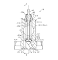
- Sectional drawing which shows the valve part of the fluid control valve which concerns on 1st Embodiment.
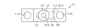
- the top view which shows a valve main body among the valve parts of FIG. FIG. 3 is a cross-sectional view of the valve portion of FIG. 1 taken along line 3-3. Sectional drawing which shows the valve part of the fluid control valve which concerns on 2nd Embodiment.
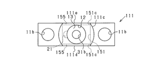
- the top view which shows a valve main body among the valve parts of FIG. Sectional drawing which shows the valve part of the fluid control valve which concerns on 4th Embodiment.
- FIG. 11 is a sectional view taken along line 11-11 in FIG. 10;
- FIG. 12 is a sectional view taken along line 12-12 of FIG.
- the rear view of the valve main body of FIG. The front view which shows the valve main body of the fluid control valve which concerns on 6th Embodiment.
- FIG. 15 is a sectional view taken along line 15-15 in FIG. 14;
- FIG. 16 is a sectional view taken along line 16-16 in FIG. 15;
- the front view which shows the valve main body of the fluid control valve which concerns on 7th Embodiment. 18 is a cross-sectional view taken along line 18-18 in FIG.
- FIG. 19 is a cross-sectional view taken along line 19-19 of FIG.
- the rear view of the valve main body of FIG. The front view which shows the valve main body of the fluid control valve which concerns on 8th Embodiment.
- FIG. 22 is a sectional view taken along line 22-22 in FIG.
- FIG. 23 is a sectional view taken along line 23-23 in FIG. 22;
- a front view showing a valve main part of a fluid control valve concerning an 11th embodiment The front view which shows the valve main body of the fluid control valve which concerns on 12th Embodiment.
- FIGS. 1 is a cross-sectional view showing a valve portion 10 of a fluid control valve according to the present embodiment
- FIG. 2 is a top view showing a valve main body 11 of the valve portion 10 in FIG. 1
- FIG. 3 is 3 of the valve portion 10 in FIG. FIG.
- the fluid control valve includes a valve unit 10 that controls fluid and an actuator unit (not shown) that applies a driving force to the valve unit 10.
- an actuator unit a pneumatic device, an electromagnetic solenoid, a piezoelectric element, a motor, or the like can be used.
- An actuator unit is connected to the valve unit 10 via an adapter (not shown).
- the valve unit 10 includes a valve body 11, a holder 41, a stem 42, a compression spring 43, a valve body 45, a bellows 48, and the like.
- the valve body 11 is formed in a block shape (generally a rectangular parallelepiped shape). In the top view shown in FIG. 2, the vertical width (vertical width in FIG. 2) of the valve body 11 is narrower than the horizontal width (horizontal width in FIG. 2).
- the valve body 11 has a vertical width of about 10 mm and a horizontal width of about 33 mm.
- Bolt holes 11b are formed at both ends of the valve body 11 in the width direction. Bolts or the like that connect the valve body 11 to other flow path blocks or devices are inserted into the bolt holes 11b.
- a valve chamber 12 is formed inside the valve body 11.
- the valve chamber 12 extends upward from the middle of the valve body 11 in the height direction (vertical direction in FIG. 1), and is a cylindrical space.
- the valve chamber 12 is formed in the center in the vertical width direction and in the center in the horizontal width direction in a top view shown in FIG.
- the upper end of the valve chamber 12 opens at the upper surface of the valve body 11.
- a first flow path 21 and a second flow path 31 are formed, each opening at the lower surface 11 a of the valve body 11.
- the first channel 21 and the second channel 31 are formed side by side in the lateral width direction of the valve body 11.
- the opening 21 a on the lower surface 11 a of the first flow path 21 and the opening 31 a on the lower surface 11 a of the second flow path 31 are formed side by side in the lateral width direction of the valve body 11.
- an annular first annular recess 22 is formed around the opening 21a of the first flow path 21.
- an annular second annular recess 32 is formed around the opening 31a of the second flow path 31.
- the first flow path 21 and the second flow path 31 are each connected to the valve chamber 12.
- the first flow path 21 is connected to the outer peripheral edge of the valve chamber 12 from the bottom to the middle of the valve chamber 12.
- the second flow path 31 is connected to the center of the bottom of the valve chamber 12.
- an annular valve seat 13 is formed around the opening 31 b in the valve chamber 12 of the second flow path 31.
- the valve seat 13 is formed in the bottom part of the valve chamber 12, and is formed in parallel with the lower surface 11a.
- the holder 41 is fixed to the upper part of the valve body 11 by welding.
- a welded portion 41 a between the valve body 11 and the holder 41 is sealed between the valve body 11 and the holder 41.
- the holder 41 is formed in a cylindrical shape.
- a cylindrical stem 42 is inserted into the holder 41.
- the stem 42 is slidably supported by the inner peripheral surface of the holder 41.
- a valve body holding portion 42 a is provided at the lower portion of the stem 42.
- the valve body 45 is held by the valve body holding part 42a.
- the valve body 45 is formed in a disk shape from a fluorine resin having chemical resistance.
- the valve body 45 can also be formed of an elastic body or the like.
- the valve body 45 faces the second flow path 31 and the valve seat 13.
- An annular convex portion is formed at a portion of the valve body 45 facing the valve seat 13.
- a compression spring 43 is held on the top of the holder 41.
- One end of the compression spring 43 is supported on the upper portion of the holder 41, and the other end is supported by a spring presser 43 a attached to the stem 42.
- the compression spring 43 biases the stem 42 in a direction in which the stem 42 is separated from the valve seat 13.
- the outer periphery of the cylindrical portion 42 b of the stem 42 and the cylindrical portion 41 b of the holder 41 is covered with a bellows 48.
- One end of the bellows 48 is connected to the upper portion of the cylindrical portion 41b of the holder 41, and the other end of the bellows 48 is connected to the lower portion of the column portion 42b of the stem 42, specifically, the valve body holding portion 42a.
- the bellows 48 blocks the cylindrical portion 42 b of the stem 42 and the cylindrical portion 41 b of the holder 41 from the valve chamber 12.
- a driving force is applied to the stem 42 by the actuator unit.
- the stem 42 is reciprocated in the direction of the valve seat 13 by the driving force and the biasing force of the compression spring 43.
- the valve body 45 is brought into contact with and separated from the valve seat 13.
- the valve body 45 comes into contact with the valve seat 13
- the second flow path 31 and the valve chamber 12 are blocked, and as a result, the second flow path 31 and the first flow path 21 are blocked.
- the valve body 45 is separated from the valve seat 13
- the second flow path 31 and the valve chamber 12 are communicated, and as a result, the second flow path 31 and the first flow path 21 are communicated via the valve chamber 12. .
- One of the first channel 21 and the second channel 31 is a fluid inflow channel, and the other is a fluid outflow channel.
- Either the first channel 21 or the second channel 31 may be used as a fluid inflow channel.
- the fluid may be a gas or a liquid.
- As the gas reactive gas, nitrogen, air, or the like can be employed.
- As the liquid a chemical solution, water, oil or the like can be used.
- the 1st flow path 21 and the 2nd flow path 31 are connected, the fluid flows in into the valve chamber 12 from one side used as an inflow flow path, and from the other used as an outflow flow path via the valve chamber 12 Fluid flows out.
- the first flow path 21 and the second flow path 31 are blocked, the fluid flow is stopped.
- the valve main body 11 is formed with a through hole 51 penetrating from the end surface 11c in the lateral width direction to the valve chamber 12.
- the through hole 51 penetrates from the end surface 11 c to the first flow path 21 through the valve chamber 12.
- the cross section of the through hole 51 is circular.
- the through hole 51 is connected to the upper end portion of the first flow path 21 (first connection flow path). That is, at the upper end portion of the first flow path 21, the first flow path 21, the valve chamber 12, and the through hole 51 are connected to each other.
- the diameter of the through hole 51 is larger than the diameter of the first flow path 21, and the cross-sectional area of the through hole 51 is larger than the cross-sectional area of the first flow path 21.
- the opening 51c in the end surface 11c of the through hole 51 is closed by a lid 55 (a closing member, a second closing member). Specifically, the opening 51c is closed by the lid 55 by welding the lid 55 to the opening 51c. The opening 51c can be closed by the lid 55 by adhering the lid 55 to the opening 51c with an adhesive or the like.
- the lid 55 is formed of a plate material similar to the cross-sectional shape of the through-hole 51, that is, a circular plate material. The lid 55 is attached to the end surface 11c.
- the through-hole 51 is formed by cutting the valve body 11 from the end face 11c in the lateral width direction. After the valve body 11 is cut to a position that penetrates the valve chamber 12, the valve body 11 is further cut to a position that penetrates the first flow path 21, thereby forming the through hole 51. Thereafter, the opening 51 c of the through hole 51 is closed by the lid 55. Note that either the valve chamber 12 or the through hole 51 may be formed in the valve body 11 first.
- valve body 11 a through hole 51 penetrating from the lateral end face 11c to the valve chamber 12 is formed, and provided with a lid 55 for closing the opening 51c in the end face 11c of the through hole 51. For this reason, the space in the valve chamber 12 can be expanded by the through hole 51, and the fluid can be easily circulated in the valve chamber 12.
- the valve body 11 is cut from the end surface 11c in the width direction to form the through hole 51, and the opening 51c at the end surface 11c of the through hole 51 is closed by the lid 55, so that the valve chamber 12 can be freely shaped or Can be easily expanded to dimensions.
- the space around the bellows 48 can be enlarged by the through hole 51. For this reason, the fluid can be easily circulated around the bellows 48.
- the through hole 51 penetrates from the end face 11c in the width direction of the valve body 11 to the valve chamber 12, and penetrates to the first flow path 21 through the valve chamber 12. For this reason, the flow path area of the connection portion between the first flow path 21 and the valve chamber 12 can be enlarged by the through hole 51.
- the diameter of the through hole 51 is larger than the diameter of the first flow path 21, and the cross-sectional area of the through hole 51 is larger than the cross-sectional area of the first flow path 21. For this reason, the flow path area of the connection part of the 1st flow path 21 and the valve chamber 12 can be expanded easily.
- FIG. 4 is a cross-sectional view showing the valve portion 10 of the fluid control valve according to the present embodiment
- FIG. 5 is a top view showing the valve body 111 of the valve portion 10 of FIG.
- the description is abbreviate
- the schematic shape of the valve body 111 is the same as that of the valve body 11 of the first embodiment, but the end surface 111c in the lateral width direction is formed in a curved shape.
- a through hole 151 is formed in the valve body 111 instead of the through hole 51 of the first embodiment.
- a lid 155 is provided instead of the lid 55 of the first embodiment.
- Other configurations are basically the same as those of the first embodiment.
- the valve body 111 is formed with a through hole 151 that penetrates from the first end surface 111 d in the longitudinal width direction of the valve body 111 to the valve chamber 12.
- the through hole 151 penetrates from the first end surface 111d to the second end surface 111e via the valve chamber 12.
- the cross section of the through hole 151 is circular.
- the through hole 151 is connected to the upper end portion of the first flow path 21 (first connection flow path). That is, at the upper end portion of the first flow path 21, the first flow path 21, the valve chamber 12, and the through hole 151 are connected to each other.
- the diameter of the through hole 151 is larger than the diameters of the first flow path 21 and the valve chamber 12, and the cross sectional area of the through hole 151 is larger than the cross sectional areas of the first flow path 21 and the valve chamber 12.
- Each opening 151c in the first end surface 111d and the second end surface 111e of the through hole 151 is closed by a lid 155 (a closing member, a second closing member).
- the lid 155 is formed of a plate material similar to the cross-sectional shape of the through-hole 151, that is, a circular plate material.
- the lid 155 is attached to the first end surface 111d and the second end surface 111e, respectively.
- the through-hole 151 is formed by cutting the valve body 111 from the first end surface 111d in the vertical width direction. After the valve body 111 is cut to a position penetrating the valve chamber 12, the valve body 111 is further cut to a position penetrating the second end face 111e, whereby the through hole 151 is formed. Thereafter, the opening 151 c of the through hole 151 is closed by the lid 155. Note that either the valve chamber 12 or the through hole 151 may be formed in the valve body 111 first.
- the valve body 111 has a through-hole 151 penetrating from the first end surface 111d in the vertical width direction to the valve chamber 12, and includes a lid 155 that closes the opening 151c at the first end surface 111d of the through-hole 151. ing. For this reason, the space in the valve chamber 12 can be expanded by the through-hole 151, and the fluid can be easily circulated in the valve chamber 12.
- the valve body 111 is cut from the first end surface 111 d in the longitudinal direction to form the through hole 151, and the opening 151 c at the first end surface 111 d of the through hole 151 is closed by the lid 155, so that the valve chamber 12 is formed. Can be easily expanded to a free shape and size.
- the through hole 151 penetrates from the first end surface 111 d in the vertical width direction of the valve body 111 to the valve chamber 12 and is connected to the first flow path 21. For this reason, the flow path area of the connection part of the 1st flow path 21 and the valve chamber 12 can be expanded by the through-hole 151.
- the through hole 151 penetrates from the first end surface 111d in the vertical width direction of the valve body 111 to the second end surface 111e via the valve chamber 12. And the opening in the 1st end surface 111d and the 2nd end surface 111e of the through-hole 151 is obstruct
- the diameter of the through hole 51 is larger than the diameter of the first flow path 21 and the valve chamber 12, and the cross-sectional area of the through hole 51 is larger than the cross-sectional area of the first flow path 21 and the valve chamber 12. . For this reason, the flow path area of the connection part of the 1st flow path 21 and the valve chamber 12 and the flow path area of the valve chamber 12 can be expanded easily.
- FIG. 6 is a cross-sectional view showing the valve portion 10 of the fluid control valve according to the present embodiment
- FIG. 7 is a top view showing the valve body 211 of the valve portion 10 of FIG.
- the description is abbreviate
- the schematic shape of the valve body 211 is the same as that of the valve body 11 of the first embodiment, but the end surface 111c in the lateral width direction is formed in a curved surface shape.
- a through hole 251 is formed in the valve body 211 instead of the through hole 51 of the first embodiment.
- a through hole 251 is formed instead of the through hole 151 of the second embodiment.
- a lid 255 is provided instead of the lid 55 of the first embodiment.
- a lid 255 is provided instead of the lid 155 of the second embodiment.
- Other configurations are basically the same as those of the first embodiment.
- the valve body 211 is formed with a through hole 251 penetrating from the end surface 211 d in the vertical width direction of the valve body 211 to the valve chamber 12.
- the cross section of the through hole 251 is an oval.
- the through hole 251 is formed in a range including the position of the valve seat 13 in the height direction of the valve body 211.
- the through hole 251 is formed at the same position as the valve chamber 12 and the valve seat 13 in the lateral width direction of the valve body 211.
- the long diameter of the through hole 251 is substantially equal to the diameter of the valve chamber 12.
- the opening 251c at the end surface 211d of the through hole 251 is closed by a lid 255 (a closing member, a second closing member).
- the lid 255 is formed of a plate similar to the cross-sectional shape of the through-hole 251, that is, an oval plate.
- the lid 255 is attached to the end surface 211d.
- the through hole 251 is formed by cutting the valve body 211 from the end surface 211d in the vertical width direction.
- the through hole 251 is formed by cutting the valve main body 211 to a position penetrating the valve chamber 12. Thereafter, the opening 251 c of the through hole 251 is closed by the lid 255. Note that either the valve chamber 12 or the through hole 251 may be formed in the valve body 211 first.
- the through hole 251 is formed in a range including the position of the valve seat 13 in the height direction of the valve body 211, the space around the valve seat 13 in the valve chamber 12 can be enlarged. For this reason, it becomes easy to circulate the fluid around the valve seat 13, and as a result, it becomes easy to circulate the fluid between the second flow path 31 and the valve chamber 12 that open inside the valve seat 13.
- FIG. 8 is a cross-sectional view showing the valve portion 10 of the fluid control valve according to the present embodiment
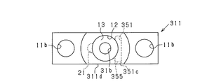
- FIG. 9 is a top view showing the valve body 311 in the valve portion 10 of FIG.
- the description is abbreviate
- the general shape of the valve body 311 is the same as that of the valve body 11 of the first embodiment, but the end surface 111c in the lateral width direction is formed in a curved surface shape.
- a through hole 351 is formed in the valve body 311 instead of the through hole 51 of the first embodiment.
- a through hole 351 is formed instead of the through hole 251 of the third embodiment.
- a lid 355 is provided instead of the lid 55 of the first embodiment.
- a lid 355 is provided instead of the lid 255 of the third embodiment.
- Other configurations are basically the same as those of the first embodiment.
- the valve body 311 is formed with a through-hole 351 that penetrates from the end surface 311 d in the vertical width direction of the valve body 311 to the valve chamber 12.
- the cross section of the through hole 351 is circular.
- the through hole 351 is formed in a range including the position of the valve seat 13 in the height direction of the valve body 311.
- the through hole 351 is formed at a position opposite to the first flow path 21 of the valve chamber 12 and the valve seat 13. That is, the first flow path 21 and the through hole 351 are opposed to each other with the bellows 48 and the valve chamber 12 interposed therebetween.
- the opening 351c at the end surface 311d of the through hole 351 is closed by a lid 355 (a closing member, a second closing member).
- the lid 355 is formed of a plate material similar to the cross-sectional shape of the through hole 351, that is, a circular plate material.
- the lid 355 is attached to the end surface 311d.
- the through hole 351 is formed by cutting the valve body 311 from the end surface 311d in the vertical width direction.
- the through hole 351 is formed by cutting the valve main body 311 to a position penetrating part of the valve chamber 12 and the valve seat 13. Thereafter, the opening 351 c of the through hole 351 is closed by the lid 355. Note that either the valve chamber 12 or the through hole 351 may be formed in the valve body 311 first.
- the first flow path 21 and the through hole 351 are opposed to each other with the bellows 48 and the valve chamber 12 interposed therebetween. For this reason, when the 1st flow path 21 turns into an inflow flow path, the space of the part which the fluid on the opposite side to the 1st flow path 21 cannot flow through the bellows 48 can be expanded. Therefore, it is easy to circulate the fluid around the valve seat 13 to the portion opposite to the first flow path 21. As a result, the fluid is circulated between the second flow path 31 opened inside the valve seat 13 and the valve chamber 12. It becomes easy.
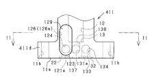
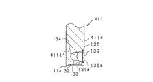
- FIG. 10 is a front view showing the valve body 411 of the fluid control valve according to the present embodiment
- FIG. 11 is a sectional view taken along the line 11-11 in FIG. 10
- FIG. 12 is a sectional view taken along the line 12-12 in FIG.
- FIG. 13 is a rear view of the valve body 411 of FIG.
- the description is abbreviate
- valve body 411 Schematic shape of the valve body 411 is the same as that of the valve body 11 of the first embodiment.
- the valve body 411 is not formed with the through hole 51 of the first embodiment, and the first flow path 21 and the second flow path of the first embodiment.
- the configuration of 31 has been changed.
- Other configurations are basically the same as those of the first embodiment.
- a first vertical flow path 123 (first flow path) and a second vertical flow path 133 (second flow path) are formed, each opening at the lower surface 11a of the valve main body 411.
- the first vertical channel 123 and the second vertical channel 133 extend from the first annular recess 22 and the second annular recess 32 in a direction perpendicular to the lower surface 11a, respectively.
- the first vertical channel 123 and the second vertical channel 133 are formed side by side in the lateral width direction of the valve body 411.
- the opening 121a on the lower surface 11a of the first vertical channel 123 and the opening 131a on the lower surface 11a of the second vertical channel 133 are formed side by side in the lateral width direction of the valve body 411.
- annular first annular recess 22 is formed around the opening 121a of the first vertical flow path 123.
- annular second annular recess 32 is formed around the opening 131a of the second vertical flow path 133.
- the first vertical flow path 123 and the second vertical flow path 133 are connected to the valve chamber 12 by a first connection flow path and a second connection flow path, respectively.
- the first connection flow path includes a first end face flow path formed by the first groove-shaped recess 126 and the lid 129 (first closing member).
- the first groove-shaped recess 126 is a groove-shaped recess, and opens in the first end surface 411d in the vertical width direction in the valve body 411.
- the length in the height direction of the valve body 411 in the first groove-shaped recess 126 (first end surface flow path) is longer than the length in the width direction of the valve body 411 in the first groove-shaped recess 126.
- the first groove-shaped recess 126 is connected to the first vertical flow path 123 by a first horizontal flow path 124 that extends in the vertical width direction (horizontal direction) in the valve body 411.
- the first groove-shaped recess 126 is opened in the valve chamber 12.
- the first groove-shaped recess 126 is connected to the outer peripheral edge of the valve chamber 12 from the bottom to the middle of the valve chamber 12.
- the opening 126a at the first end surface 411d of the first groove-shaped recess 126 is closed by a lid 129.
- the opening 126a is closed by the lid 129 by welding the lid 129 to the opening 126a.
- the lid 129 is formed of a plate material similar to the shape of the opening 126a of the first groove-shaped recess 126, that is, an oval plate material.
- the lid 129 is attached to the first end surface 411d.
- the first groove-shaped recess 126 is formed by cutting the valve body 411 from the first end surface 411d in the vertical width direction. After forming the first groove-shaped recess 126, the first horizontal flow path 124 is formed by cutting the valve body 411 in the vertical width direction. Thereafter, the opening 126 a of the first groove-shaped recess 126 is closed by the lid 129. Note that any of the valve chamber 12, the first vertical flow path 123, the first groove-shaped recess 126, and the first horizontal flow path 124 may be formed in the valve body 411 first.
- the second connection flow path includes a second end face flow path formed by the second groove-shaped recess 136 and the lid 139 (first closing member).
- the second groove-shaped recess 136 is a groove-shaped recess and opens in the second end surface 411 e in the longitudinal width direction in the valve body 411.
- the length in the width direction of the valve body 411 in the second groove-shaped recess 136 (second end surface flow path) is longer than the length in the height direction of the valve body 411 in the second groove-shaped recess 136.
- the second groove-shaped recess 136 is connected to the second vertical flow path 133 by a second horizontal flow path 134 that extends in the longitudinal width direction (horizontal direction) in the valve body 411.
- the second groove-shaped recess 136 is connected to a third horizontal flow path 137 extending in the longitudinal width direction (horizontal direction) in the valve body 411.
- the third horizontal channel 137 is connected to a third vertical channel 138 that extends in a direction perpendicular to the lower surface 11 a and opens to the valve chamber 12.
- the third vertical flow path 138 opens at the bottom of the valve chamber 12.
- an annular valve seat 13 is formed around the opening of the third vertical flow path 138 in the valve chamber 12.
- the opening 136 a at the second end surface 411 e of the second groove-shaped recess 136 is closed by a lid 139.
- the lid 139 is formed of a plate material similar to the shape of the opening 136a of the second groove-shaped recess 136, that is, an oval plate material.
- the lid 139 is attached to the second end surface 411e.
- the second groove-shaped recess 136 is formed by cutting the valve body 411 from the second end surface 411e in the vertical width direction. After the second groove-shaped recess 136 is formed, the second horizontal flow path 134 and the third horizontal flow path 137 are formed by cutting the valve body 411 in the vertical width direction. Further, the third vertical flow path 138 is formed by cutting the valve body 411 in the height direction. Thereafter, the opening 136 a of the second groove-shaped recess 136 is closed by the lid 139. Note that any of the second groove-shaped recess 136, the second horizontal flow path 134, the third horizontal flow path 137, and the third vertical flow path 138 may be formed in the valve body 411 first.
- the 1st flow path is comprised by the 1st vertical flow path 123, the 1st horizontal flow path 124, and the 1st end surface flow path (The 1st groove-shaped recessed part 126 and the lid
- the first horizontal flow path 124 and the first end face flow path constitute a first connection flow path.
- the second horizontal flow path 134, the second end face flow path, the third horizontal flow path 137, and the third vertical flow path 138 constitute a second connection flow path.
- the first channel includes a first vertical channel 123 extending from the first annular recess 22 in a direction perpendicular to the lower surface 11a of the valve body 411, and the second channel extends from the second annular recess 32 to the valve body 411.
- a second vertical flow path 133 extending in a direction perpendicular to the lower surface 11a is included. For this reason, the first flow path and the second flow path can be vertically connected to the annular recesses 22 and 32, respectively, and the annular recesses 22 and 32 interfere with the first flow path and the second flow path, respectively. This can be suppressed.
- the channel area of the part can be increased.
- the first connection flow path includes a groove-shaped first groove-shaped recess 126 that opens to the first end surface 411d in the longitudinal direction of the valve body 411, and a lid 129 that closes the opening 126a of the first groove-shaped recess 126.
- the first end face flow path is formed by cutting the first end face 411d in the longitudinal direction of the valve body 411 into a groove shape to form the first groove-like recess 126, and the opening 126a of the first groove-like recess 126 is formed by the lid 129.
- By closing it can be easily formed into a free shape and size. Therefore, even if the first channel and the second channel are vertically connected to the annular recesses 22 and 32, the channel area of the first connection channel is formed by forming the first end surface channel. Can be secured. As a result, it is possible to suppress the maximum flow rate from being limited in the small fluid control valve.
- the second connection flow path is formed by a groove-shaped second groove-shaped recess 136 that opens to the second end surface in the longitudinal direction of the valve body 411 and a lid 139 that closes the opening 136a of the second groove-shaped recess 136.
- a second end face flow path For this reason, it becomes easy to ensure the flow path area of the 2nd connection flow path, and the freedom degree which arrange
- the length in the height direction of the valve body 411 in the first end face flow path is longer than the length in the width direction of the valve body 411 in the first end face flow path. For this reason, the first connection channel can be extended in the height direction of the valve body 411 while ensuring the channel area of the first connection channel, and the arrangement of the first connection channel can be facilitated. .
- the first end face flow path is opened in the valve chamber 12, the first connection flow path can be easily connected to the valve chamber 12, and the connection portion between the first connection flow path and the valve chamber 12 The channel area can be easily secured.
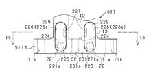
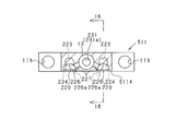
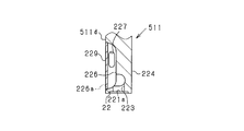
- FIG. 14 is a front view showing a valve main body 511 of the fluid control valve according to the present embodiment
- FIG. 15 is a sectional view taken along line 15-15 of FIG. 14
- FIG. 16 is a sectional view taken along line 16-16 of FIG. is there.
- the description is abbreviate
- first vertical flow paths 223 first flow paths
- second flow path 231 are formed, each opening on the lower surface 11a of the valve main body 511.
- the first vertical channel 223 and the second channel 231 extend in a direction perpendicular to the lower surface 11a from the first annular recess 22 and the second annular recess 32, respectively.
- the two first vertical channels 223 and the second channel 231 are formed side by side in the lateral direction of the valve body 511.
- the opening 221 a on the lower surface 11 a of the two first vertical channels 223 and the opening 231 a on the lower surface 11 a of the second channel 231 are formed side by side in the lateral width direction of the valve body 511.
- annular first annular recesses 22 are formed around the openings 221a of the two first vertical flow paths 223, respectively.
- annular second annular recess 32 is formed around the opening 231 a of the second flow path 231.
- the two first vertical channels 223 are each connected to the valve chamber 12 by a first connection channel.
- the first connection flow path includes a first end face flow path formed by the first groove-shaped recess 226 and the lid 229 (first closing member).
- the first groove-like recess 226 is a groove-like recess, and is open to the first end surface 511d in the longitudinal direction of the valve body 511.
- the length in the height direction of the valve body 511 in the first groove-shaped recess 226 (first end surface flow path) is longer than the length in the width direction of the valve body 511 in the first groove-shaped recess 226.
- the first groove-shaped recess 226 is connected to the first vertical flow path 223 by a first horizontal flow path 224 that extends in the longitudinal width direction (horizontal direction) in the valve body 511.
- the first groove-shaped recess 226 is connected to the valve chamber 12 by a fourth horizontal flow path 227 that extends in the valve body 511 in the direction of the valve chamber 12 (horizontal direction).
- the second flow path 231 (second connection flow path) is open at the bottom of the valve chamber 12.
- an annular valve seat 13 is formed around the opening of the second flow path 231 in the valve chamber 12.
- the first flow path is constituted by the first vertical flow path 223, the first horizontal flow path 224, the first end face flow path (the first groove-shaped recess 226 and the lid 229), and the fourth horizontal flow path 227. Yes.
- the first horizontal flow path 224, the first end face flow path, and the fourth horizontal flow path 227 constitute a first connection flow path.
- One of the two first flow paths can also be regarded as the second flow path.
- a three-port fluid control valve including two first flow paths and one second flow path 231 can be manufactured. In each of the three channels, the channel area can be ensured.
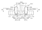
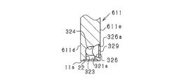
- FIG. 17 is a front view showing a valve main body 611 of the fluid control valve according to the present embodiment
- FIG. 18 is a sectional view taken along line 18-18 in FIG. 17
- FIG. 19 is a sectional view taken along line 19-19 in FIG.
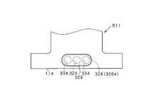
- FIG. 20 is a rear view of the valve body 611 of FIG.
- the description is abbreviate
- valve body 611 is formed with two valve chambers 12 (first valve chamber and second valve chamber) and two second flow paths,
- the configuration of the first flow path of the fifth embodiment is changed.
- Other configurations are basically the same as those of the fifth embodiment.
- a first vertical flow path 323 (first flow path) and two second vertical flow paths 333 (second flow paths) are formed in the valve main body 611 and open on the lower surface 11a of the valve main body 611. .
- the first vertical channel 323 and the second vertical channel 333 extend in a direction perpendicular to the lower surface 11a from the first annular recess 22 and the second annular recess 32, respectively.
- the first vertical flow path 323 and the two second vertical flow paths 333 are formed side by side in the lateral width direction of the valve body 611.
- the opening 321a on the lower surface 11a of the first vertical channel 323 and the opening 331a on the lower surface 11a of the two second vertical channels 333 are formed side by side in the lateral width direction of the valve body 611.
- annular first annular recess 22 is formed around the opening 321a of the first vertical flow path 323.
- annular second annular recesses 32 are formed around the openings 331a of the two second vertical flow paths 333, respectively.
- the first vertical channel 323 and the second vertical channel 333 are connected to the valve chamber 12 by a first connection channel and a second connection channel, respectively.
- the first connection flow path includes a first end face flow path formed by the first groove-shaped recess 326 and the lid 329 (first closing member).
- the first groove-shaped recess 326 is a groove-shaped recess, and opens in the second end surface 611 e in the vertical width direction in the valve body 611.
- the length of the valve body 611 in the width direction of the first groove-shaped recess 326 (first end surface flow path) is longer than the length of the valve body 611 in the height direction of the first groove-shaped recess 326.
- the first groove-shaped recess 326 extends to the same position as the valve seats 13 of the two valve chambers 12 in the lateral width direction of the valve body 611.
- the central portion of the first groove-shaped recess 326 in the horizontal width direction of the valve body 611 is connected to the first vertical flow path 323 by a first horizontal flow path 324 extending in the vertical width direction (horizontal direction) in the valve body 611. .
- the first groove-shaped recess 326 is connected to two second horizontal flow paths 327 extending in the longitudinal width direction (horizontal direction) in the valve body 611.
- the second horizontal flow paths 327 are connected to third vertical flow paths 328 that extend in a direction perpendicular to the lower surface 11a and open to the two valve chambers 12, respectively.
- the opening 326a in the second end surface 611e of the first groove-shaped recess 326 is closed by a lid 329.
- the lid 329 is formed of a plate material similar to the shape of the opening 326a of the first groove-shaped recess 326, that is, an oval plate material.
- the lid 329 is attached to the second end surface 611e.
- 1st groove-shaped recessed part 326 is formed by cutting the valve main body 611 from the 2nd end surface 611e to the vertical width direction. After the first groove-shaped recess 326 is formed, the first horizontal flow path 324 is formed by cutting the valve main body 611 in the vertical width direction, and the second horizontal flow path 327 cuts the valve main body 611 in the vertical width direction. Is formed. Thereafter, the opening 326 a of the first groove-shaped recess 326 is closed by the lid 129. Note that any one of the valve chamber 12, the first vertical flow path 323, the first groove-shaped recess 326, the first horizontal flow path 324, and the second horizontal flow path 327 may be formed in the valve body 611 first. .
- the 2nd connection channel is formed in valve body 611 like the 1st connection channel of a 5th embodiment.
- the second connection flow paths are respectively formed corresponding to the two valve chambers 12.
- the first flow path is constituted by the first vertical flow path 323, the first horizontal flow path 324, the first end face flow path (the first groove-shaped recess 326 and the lid 329), and the second horizontal flow path 327. Yes.
- the first horizontal flow path 324, the first end surface flow path, and the second horizontal flow path 327 constitute a first connection flow path.
- the second vertical flow path 333, the second horizontal flow path 334, and the second end face flow path (the second groove-shaped recess 336 and the lid 339) constitute a second flow path.
- the second horizontal flow path 334 and the second end face flow path constitute a second connection flow path.
- Two valve chambers 12 are formed inside the valve body 611, and the first connection flow path is the first vertical flow path 323 and the two valve chambers 12. Is connected. For this reason, in the merging valve or the diversion valve provided with the two valve chambers 12, the flow area of each flow path can be ensured.
- a three-port fluid control valve including one first flow path and two second flow paths can be manufactured. In each of the three channels, the channel area can be ensured.
- the length of the valve body 611 in the width direction in the first end face flow path is longer than the length in the height direction of the valve body 611 in the first end face flow path. For this reason, the first connection channel can be extended in the lateral width direction of the valve body 611 while ensuring the channel area of the first connection channel, and the arrangement of the first connection channel can be facilitated.
- the second connection flow path can be easily connected to the valve chamber 12, and the connection portion between the second connection flow path and the valve chamber 12 The channel area can be easily secured.
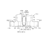
- FIG. 21 is a front view showing a valve body 711 of the fluid control valve according to the present embodiment
- FIG. 22 is a sectional view taken along line 22-22 of FIG. 21
- FIG. 23 is a sectional view taken along line 23-23 of FIG. is there.
- the description is abbreviate
- valve body 711 is formed with two valve chambers 12 (first valve chamber and second valve chamber) and two second flow paths,
- the configuration of the first flow path of the sixth embodiment is changed corresponding to the two valve chambers 12.
- Other configurations are basically the same as those of the sixth embodiment.
- the first vertical channel 423 is connected to the two valve chambers 12 by the first connection channel.
- the first connection flow path includes a first end face flow path formed by the first groove-shaped recess 426 and the lid 429 (first closing member).
- the first groove-shaped recess 426 is a groove-shaped recess, and is open to the first end surface 711 d in the vertical width direction in the valve body 711.
- the length in the height direction of the valve body 711 in the first groove-shaped recess 426 (first end surface flow path) is longer than the length in the width direction of the valve body 711 in the first groove-shaped recess 426.
- the first groove-shaped recess 426 is connected to the first vertical flow path 423 by a first horizontal flow path 424 that extends in the longitudinal width direction (horizontal direction) in the valve body 711.
- the first groove-like recesses 426 are respectively connected to the two valve chambers 12 by fourth horizontal flow paths 427 extending in the direction (horizontal direction) of the two valve chambers 12 in the valve body 711.
- the second flow path 431 (second connection flow path) opens at the bottom of the valve chamber 12.
- annular valve seat 13 is formed around the opening of the second flow path 431 in the valve chamber 12.
- the first flow path is constituted by the first vertical flow path 423, the first horizontal flow path 424, the first end face flow path (the first groove-shaped recess 426 and the lid 429), and the fourth horizontal flow path 427. Yes.
- the first horizontal flow path 424, the first end face flow path, and the fourth horizontal flow path 427 constitute a first connection flow path.
- Two valve chambers 12 are formed inside the valve main body 711, and the first connection channel is the first vertical channel 423 and the two valve chambers 12. Is connected. For this reason, in the merging valve or the diversion valve provided with the two valve chambers 12, the flow area of each flow path can be ensured.
- FIG. 24 is a front view showing a valve body 811 of the fluid control valve according to the present embodiment.
- the description is abbreviate
- the flow path structure of the small fluid control valve of the present embodiment is the same as the flow path structure of the fifth embodiment, in which the through hole 51 of the first embodiment is formed and the opening 51c of the through hole 51 is closed by the lid 55. is there. Therefore, this embodiment has the same advantages as the first embodiment and the fifth embodiment.
- FIG. 25 is a front view showing a valve main body 911 of the fluid control valve according to the present embodiment.
- the description is abbreviate
- the flow path structure of the small fluid control valve of the present embodiment is the same as the flow path structure of the fifth embodiment, in which the through hole 151 of the second embodiment is formed, and the opening 151c of the through hole 151 and the first groove-shaped recess 126 are formed.
- the opening 126a is closed with a lid 529. Therefore, this embodiment has the same advantages as those of the second and fifth embodiments.
- FIG. 26 is a front view showing the valve main body 1011 of the fluid control valve according to the present embodiment.
- the description is abbreviate
- the flow path structure of the small fluid control valve of the present embodiment is the same as the flow path structure of the seventh embodiment, in which the through hole 151 of the second embodiment is formed, and the opening 151c of the through hole 151 and the first groove-shaped recess 326 are formed.
- the opening 326a is closed by a lid 529. Therefore, this embodiment has the same advantages as the second embodiment and the seventh embodiment.
- this embodiment has the following advantages. Here, only advantages different from the above-described embodiments will be described.
- the through hole 151 penetrates from the end face 1011d in the longitudinal direction of the valve body 1011 to the valve chamber 12, and is connected to the second connection flow path. For this reason, the flow path area of the connection part of a 2nd connection flow path and the valve chamber 12 can be expanded by a through-hole.
- FIG. 27 is a front view showing a valve main body 1111 of the fluid control valve according to the present embodiment.
- the description is abbreviate
- the flow path structure of the small fluid control valve of the present embodiment is the same as the flow path structure of the fifth embodiment, in which the through hole 251 of the third embodiment is formed, and the opening 251c of the through hole 251 and the first groove-shaped recess 126
- the opening 126 a is closed by a lid 629.
- the through hole 251 and the first groove-like recess 126 are formed from the end surface 1111d on the same side in the longitudinal width direction of the valve body 1111. Therefore, this embodiment has the same advantages as the third and fifth embodiments.
- FIG. 28 is a front view showing a valve main body 1211 of the fluid control valve according to the present embodiment.
- the description is abbreviate
- the flow path structure of the small fluid control valve of the present embodiment is obtained by applying the flow path structure of the fifth embodiment to a diaphragm type small fluid control valve.
- This fluid control valve includes a diaphragm 148 instead of the bellows 48 and the valve body 45 of FIG.
- the periphery of the valve seat 13 is a valve chamber 12 in a space below the diaphragm 148. According to such a configuration, there is an advantage according to the fifth embodiment.
- the first end face flow path is not limited to a structure extending perpendicularly to the lower surface 11a of the valve body, but may be a structure extending slightly inclined with respect to the lower surface 11a.
Landscapes
- Engineering & Computer Science (AREA)
- General Engineering & Computer Science (AREA)
- Mechanical Engineering (AREA)
- Valve Housings (AREA)
- Lift Valve (AREA)
Abstract
小型流体制御弁の流路構造であって、上面視において弁本体(11)の縦幅は横幅よりも狭くなっており、弁本体(11)の内部には、弁本体(11)の下面(11a)で横幅の方向に並んでそれぞれ開口する第1流路(21)及び第2流路(31)が形成されており、下面(11a)において、第1流路(21)の開口(21a)の周囲には環状の第1環状凹部(22)が形成されており、下面(11a)において、第2流路(31)の開口(31a)の周囲には環状の第2環状凹部(32)が形成されており、第1流路(21)及び第2流路(31)は、弁室(12)にそれぞれ接続されており、弁本体(11)には、横幅の方向の端面(11c)から弁室(12)まで貫通する貫通孔(51)が形成されており、貫通孔(51)の端面(11c)での開口(51c)を閉塞する閉塞部材(55)を備える。
Description
本発明は、流体を制御する小型流体制御弁の流路構造に関する。
従来、流体制御弁の弁本体の内部に、弁室と、下面で開口する第1流路及び第2流路とを形成し、第1流路及び第2流路を弁室に連通させたものがある(特許文献1参照)。特許文献1に記載の流体制御弁は、複数の弁を集積した場合の占有面積を小さくするために、幅10mm程度の小型流体制御弁となっている。
ところで、特許文献1に記載の流体制御弁では、第1流路及び第2流路の開口の周囲に、シール部材を配置するための環状の凹部を形成している。例えば、第1流路と環状の凹部とが干渉しないように、第1流路及び環状の凹部を形成する必要があるため、第1流路の形状や寸法が制限される。したがって、特許文献1に記載の小型流体制御弁では、第1流路の流路面積や、第1流路と弁室との接続部の流路面積を十分に確保することができず、流体制御弁を流通可能な流体の最大流量が制限されることとなる。
本発明は、こうした課題を解決するためになされたものであり、その主たる目的は、最大流量が制限されることを抑制することのできる小型流体制御弁の流路構造を提供することにある。
以下、上記課題を解決するための手段、及びその作用効果について記載する。
第1の手段は、弁室が内部に形成された弁本体を備える小型流体制御弁の流路構造であって、上面視において前記弁本体の縦幅は横幅よりも狭くなっており、前記弁本体の内部には、前記弁本体の下面で前記横幅の方向に並んでそれぞれ開口する第1流路及び第2流路が形成されており、前記下面において、前記第1流路の前記開口の周囲には環状の第1環状凹部が形成されており、前記下面において、前記第2流路の前記開口の周囲には環状の第2環状凹部が形成されており、前記第1流路及び前記第2流路は、前記弁室にそれぞれ接続されており、前記弁本体には、前記横幅の方向の端面から前記弁室まで貫通する貫通孔が形成されており、前記貫通孔の前記端面での開口を閉塞する閉塞部材を備える。
上記構成によれば、小型流体制御弁は弁本体を備え、弁本体の内部に弁室が形成されている。上面視において、弁本体の縦幅は横幅よりも狭くなっている。すなわち、小型流体制御弁の占有面積を小さくするために、弁本体の縦幅が狭くなっている。
弁本体の内部には、弁本体の下面で横幅の方向に並んでそれぞれ開口する第1流路及び第2流路が形成されている。弁本体の下面において、第1流路の開口の周囲には環状の第1環状凹部が形成されており、第2流路の開口の周囲には環状の第2環状凹部が形成されている。このため、小型流体制御弁を流体の流路や他の機器に接続する際に、第1環状凹部及び第2環状凹部にシール部材を配置することができる。
弁本体には、横幅の方向の端面から弁室まで貫通する貫通孔が形成されており、貫通孔の前記端面での開口を閉塞する第2閉塞部材を備えている。このため、貫通孔により弁室内の空間を拡大することができ、弁室内において流体を流通させ易くすることができる。しかも、弁本体において横幅の方向の端面から切削して貫通孔を形成し、貫通孔の前記端面での開口を第2閉塞部材により閉塞することで、弁室を自由な形状や寸法に容易に拡大することができる。
第2の手段では、前記弁本体において、前記第2流路の前記弁室での開口の周囲には環状の弁座が形成されており、前記貫通孔は、前記横幅の方向の端面から前記弁室を介して前記第1流路まで貫通している。
上記構成によれば、第1流路と弁室との接続部の流路面積を、貫通孔により拡大することができる。
第3の手段は、弁室が内部に形成された弁本体を備える小型流体制御弁の流路構造であって、上面視において前記弁本体の縦幅は横幅よりも狭くなっており、前記弁本体の内部には、前記弁本体の下面で前記横幅の方向に並んでそれぞれ開口する第1流路及び第2流路が形成されており、前記下面において、前記第1流路の前記開口の周囲には環状の第1環状凹部が形成されており、前記下面において、前記第2流路の前記開口の周囲には環状の第2環状凹部が形成されており、前記第1流路及び前記第2流路は、前記弁室にそれぞれ接続されており、前記弁本体には、前記縦幅の方向の端面から前記弁室まで貫通する貫通孔が形成されており、前記貫通孔の前記端面での開口を閉塞する閉塞部材を備える。
上記構成によれば、弁本体には、縦幅の方向の端面から弁室まで貫通する貫通孔が形成されており、貫通孔の前記端面での開口を閉塞する第2閉塞部材を備えている。このため、貫通孔により弁室内の空間を拡大することができ、弁室内において流体を流通させ易くすることができる。しかも、弁本体において縦幅の方向の端面から切削して貫通孔を形成し、貫通孔の前記端面での開口を第2閉塞部材により閉塞することで、弁室を自由な形状や寸法に容易に拡大することができる。
第4の手段では、前記弁本体において、前記第2流路の前記弁室での開口の周囲には環状の弁座が形成されており、前記貫通孔は、前記第1流路に接続されている。
上記構成によれば、第1流路と弁室との接続部の流路面積を、貫通孔により拡大することができる。
第5の手段では、前記弁本体において、前記第1流路の前記弁室での開口の周囲には環状の弁座が形成されており、前記貫通孔は、前記第2流路に接続されている。
上記構成によれば、第2流路と弁室との接続部の流路面積を、貫通孔により拡大することができる。
第6の手段では、前記端面は第1端面であり、前記貫通孔は、前記縦幅の方向の前記第1端面から前記弁室を介して第2端面まで貫通しており、前記貫通孔の前記第2端面での開口を閉塞する閉塞部材を備える。
上記構成によれば、貫通孔は、弁本体の縦幅方向の第1端面から弁室を介して第2端面まで貫通している。そして、貫通孔の前記第1端面及び第2端面での開口が、それぞれ閉塞部材により閉塞されている。このため、弁本体において縦幅方向の一方の端面から他方の端面まで切削することで、貫通孔を容易に形成することができるとともに、両端面付近において弁室を拡大することができる。
第7の手段では、前記貫通孔は、前記弁本体の高さ方向において前記弁座の位置を含む範囲に形成されている。
上記構成によれば、貫通孔は、弁本体の高さ方向において弁座の位置を含む範囲に形成されているため、弁室において弁座の周囲の空間を拡大することができる。このため、弁座の周囲に流体を流通させ易くなり、ひいては弁座の内側で開口する流路と弁室とで流体を流通させ易くなる。
第8の手段は、前記第1流路は、前記第1環状凹部から前記下面に垂直な方向へ延びる第1垂直流路と、前記第1垂直流路及び前記弁室を接続する第1接続流路とを含み、前記第2流路は、前記第2環状凹部から前記下面に垂直な方向へ延びる第2垂直流路と、前記第2垂直流路及び前記弁室を接続する第2接続流路とを含み、前記第1接続流路は、前記弁本体において前記縦幅の方向の端面に開口する溝状の第1溝状凹部と前記第1溝状凹部の開口を閉塞する閉塞部材とで形成された第1端面流路、を含む。
また、第9の手段は、弁室が内部に形成された弁本体を備える小型流体制御弁の流路構造であって、上面視において前記弁本体の縦幅は横幅よりも狭くなっており、前記弁本体の内部には、前記弁本体の下面で前記横幅の方向に並んでそれぞれ開口する第1流路及び第2流路が形成されており、前記下面において、前記第1流路の前記開口の周囲には環状の第1環状凹部が形成されており、前記下面において、前記第2流路の前記開口の周囲には環状の第2環状凹部が形成されており、前記第1流路は、前記第1環状凹部から前記下面に垂直な方向へ延びる第1垂直流路と、前記第1垂直流路及び前記弁室を接続する第1接続流路とを含み、前記第2流路は、前記第2環状凹部から前記下面に垂直な方向へ延びる第2垂直流路と、前記第2垂直流路及び前記弁室を接続する第2接続流路とを含み、前記第1接続流路は、前記弁本体において前記縦幅の方向の端面に開口する溝状の第1溝状凹部と前記第1溝状凹部の開口を閉塞する第1閉塞部材とで形成された第1端面流路、を含む。
第8、第9手段によれば、第1流路は、第1環状凹部から弁本体の下面に垂直な方向へ延びる第1垂直流路を含み、第2流路は、第2環状凹部から弁本体の下面に垂直な方向へ延びる第2垂直流路を含んでいる。このため、環状凹部に対して第1流路及び第2流路をそれぞれ垂直に接続することができ、環状凹部と第1流路及び第2流路とが干渉することを抑制することができる。したがって、環状凹部に対して第1流路及び第2流路を斜めに接続する構造と比較して、環状凹部と第1流路及び第2流路との接続部の流路面積を大きくすることができる。そして、第1垂直流路と弁室とが第1接続流路により接続され、第2垂直流路と弁室とが第2接続流路により接続されている。
ここで、環状凹部に対して第1流路及び第2流路をそれぞれ垂直に接続するためには、第1接続流路及び第2接続流路の一方、例えば第1接続流路の形状や寸法が制限されるおそれがある。この点、第1接続流路は、弁本体において縦幅の方向の端面に開口する溝状の第1溝状凹部と第1溝状凹部の開口を閉塞する第1閉塞部材とで形成された第1端面流路、を含んでいる。第1端面流路は、弁本体において縦幅の方向の端面を溝状に切削して第1溝状凹部を形成し、第1溝状凹部の開口を第1閉塞部材により閉塞することで、自由な形状や寸法に容易に形成することができる。例えば、第1溝状凹部の開口に第1閉塞部材を溶接したり、接着したりすることで、第1溝状凹部の開口を第1閉塞部材により閉塞する。したがって、環状凹部に対して第1流路及び第2流路をそれぞれ垂直に接続する構造であっても、第1端面流路を形成することにより第1接続流路の流路面積を確保することができる。その結果、小型流体制御弁において、最大流量が制限されることを抑制することができる。
第10の手段では、前記第2接続流路は、前記弁本体において前記縦幅の方向の端面に開口する溝状の第2溝状凹部と前記第2溝状凹部の開口を閉塞する第1閉塞部材とで形成された第2端面流路、を含む。
上記構成によれば、第2接続流路は、弁本体において縦幅の方向の端面に開口する溝状の第2溝状凹部と第2溝状凹部の開口を閉塞する第1閉塞部材とで形成された第2端面流路、を含んでいる。このため、第2接続流路の流路面積を確保することが容易となり、第1流路及び第2流路を配置する自由度を向上させることができる。
第11の手段では、前記弁本体には、前記第1流路が2つ形成されている。
上記構成によれば、第1流路が2つ形成されているため、2つの第1流路と1つの第2流路とを備える3ポートの流体制御弁を製造することができる。そして、3つの流路において、それぞれ流路面積を確保することができる。
第12の手段では、前記弁室は第1弁室であり、前記弁本体の内部には第2弁室が形成されており、前記第1接続流路は、前記第1垂直流路、前記第1弁室、及び前記第2弁室を接続している。
上記構成によれば、弁本体の内部には第1弁室及び第2弁室が形成されており、第1接続流路は、第1垂直流路、第1弁室、及び第2弁室を接続している。このため、第1弁室及び第2弁室を備える合流弁や分流弁において、それぞれの流路の流路面積を確保することができる。
第13の手段では、前記弁本体には、前記第2流路が2つ形成されている。
上記構成によれば、第2流路が2つ形成されているため、1つの第1流路と2つの第2流路とを備える3ポートの流体制御弁を製造することができる。そして、3つの流路において、それぞれ流路面積を確保することができる。
具体的には、第14の手段のように、前記第1端面流路における前記弁本体の高さ方向の長さは、前記第1端面流路における前記弁本体の横幅方向の長さよりも長くなっているといった構成を採用することができる。こうした構成によれば、第1接続流路の流路面積を確保しつつ、弁本体の高さ方向に第1接続流路を延ばすことができ、第1接続流路の配置を容易化することができる。
具体的には、第15の手段のように、前記弁本体において、前記第2接続流路の前記弁室での開口の周囲には環状の弁座が形成されているといった構成を採用することができる。こうした構成によれば、弁座に対して流体制御弁の弁体を当接及び離間させることにより、第2流路と弁室とを遮断及び連通させることができ、ひいては弁室を介して第2流路と第1流路とを遮断及び連通させることができる。
第16の手段では、前記第1端面流路は、前記弁室で開口している。
上記構成によれば、第1端面流路は弁室で開口しているため、第1接続流路を弁室に容易に接続することができるとともに、第1接続流路と弁室との接続部の流路面積を容易に確保することができる。
具体的には、第17の手段のように、前記第1端面流路における前記弁本体の横幅方向の長さは、前記第1端面流路における前記弁本体の高さ方向の長さよりも長くなっているといった構成を採用することができる。こうした構成によれば、第1接続流路の流路面積を確保しつつ、弁本体の横幅方向に第1接続流路を延ばすことができ、第1接続流路の配置を容易化することができる。
具体的には、第18の手段のように、前記弁本体において、前記第1接続流路の前記弁室での開口の周囲には環状の弁座が形成されているといった構成を採用することができる。こうした構成によれば、弁座に対して流体制御弁の弁体を当接及び離間させることにより、第1流路と弁室とを遮断及び連通させることができ、ひいては弁室を介して第1流路と第2流路とを遮断及び連通させることができる。
第19の手段では、前記第2接続流路は、前記弁本体において前記縦幅の方向の端面に開口する溝状の第2溝状凹部と前記第2溝状凹部の開口を閉塞する第1閉塞部材とで形成された第2端面流路、を含み、前記第2端面流路は、前記弁室で開口している。
上記構成によれば、第2端面流路は弁室で開口しているため、第2接続流路を弁室に容易に接続することができるとともに、第2接続流路と弁室との接続部の流路面積を容易に確保することができる。
第20の手段では、前記弁本体には、前記縦幅の方向の端面から前記弁室まで貫通する貫通孔が形成されており、前記貫通孔の前記端面での開口を閉塞する第2閉塞部材を備え、前記貫通孔は、前記第1接続流路に接続されている。
上記構成によれば、貫通孔は、弁本体の縦幅の方向の端面から弁室まで貫通しており、且つ第1接続流路に接続されている。このため、第1接続流路と弁室との接続部の流路面積を、貫通孔により拡大することができる。
第21の手段では、前記弁本体には、前記縦幅の方向の端面から前記弁室まで貫通する貫通孔が形成されており、前記貫通孔の前記端面での開口を閉塞する第2閉塞部材を備え、前記貫通孔は、前記第2接続流路に接続されている。
上記構成によれば、貫通孔は、弁本体の縦幅の方向の端面から弁室まで貫通しており、且つ第2接続流路に接続されている。このため、第2接続流路と弁室との接続部の流路面積を、貫通孔により拡大することができる。
第22の手段では、前記端面は第1端面であり、前記貫通孔は、前記縦幅の方向の前記第1端面から前記弁室を介して第2端面まで貫通しており、前記貫通孔の前記第2端面での開口を閉塞する第2閉塞部材を備える。
上記構成によれば、貫通孔は、弁本体の縦幅方向の第1端面から弁室を介して第2端面まで貫通している。そして、貫通孔の前記第1端面及び第2端面での開口が、それぞれ第2閉塞部材により閉塞されている。このため、弁本体において縦幅方向の一方の端面から他方の端面まで切削することで、貫通孔を容易に形成することができるとともに、両端面付近において弁室を拡大することができる。
第23の手段では、前記弁本体には、前記横幅の方向の端面から前記弁室を介して前記第1接続流路まで貫通する貫通孔が形成されており、前記貫通孔の前記端面での開口を閉塞する第2閉塞部材を備える。
上記構成によれば、貫通孔は、弁本体の横幅の方向の端面から弁室まで貫通しており、且つ弁室を介して第1接続流路まで貫通している。このため、第1接続流路と弁室との接続部の流路面積を、貫通孔により拡大することができる。
第24の手段では、前記弁本体には、前記縦幅の方向の端面から前記弁室まで貫通する貫通孔が形成されており、前記貫通孔は、前記弁本体の高さ方向において前記弁座の位置を含む範囲に形成されている。
上記構成によれば、貫通孔は、弁本体の高さ方向において弁座の位置を含む範囲に形成されているため、弁室において弁座の周囲の空間を拡大することができる。このため、弁座の周囲に流体を流通させ易くなり、ひいては弁座の内側で開口する流路と弁室とで流体を流通させ易くなる。
(第1実施形態)
以下、半導体製造装置等に用いられる小型流体制御弁として具体化した第1実施形態について、図1~3を参照して説明する。図1は本実施形態に係る流体制御弁の弁部10を示す断面図、図2は図1の弁部10のうち弁本体11を示す上面図、図3は図1の弁部10の3-3線断面図である。
以下、半導体製造装置等に用いられる小型流体制御弁として具体化した第1実施形態について、図1~3を参照して説明する。図1は本実施形態に係る流体制御弁の弁部10を示す断面図、図2は図1の弁部10のうち弁本体11を示す上面図、図3は図1の弁部10の3-3線断面図である。
流体制御弁は、流体を制御する弁部10と、弁部10に駆動力を作用させるアクチュエータ部(図示略)とを備えている。アクチュエータ部として、空圧機器、電磁ソレノイド、ピエゾ素子、モータ等を採用することができる。弁部10に、アダプタ(図示略)を介してアクチュエータ部が連結される。
弁部10は、弁本体11、ホルダ41、ステム42、圧縮ばね43、弁体45、ベローズ48等を備えている。
弁本体11は、ブロック状(概略として直方体状)に形成されている。図2に示す上面視において、弁本体11の縦幅(図2の上下方向の幅)は、横幅(図2の左右方向の幅)よりも狭くなっている。弁本体11の縦幅は略10mmであり、横幅は略33mmである。弁本体11の横幅方向の両端には、ボルト孔11bが形成されている。ボルト孔11bには、弁本体11を他の流路ブロックや機器に接続するボルト等が挿通される。
弁本体11の内部には、弁室12が形成されている。弁室12は、弁本体11の高さ方向(図1の上下方向)の中間から上方へ延びており、円柱状の空間となっている。弁室12は、図2に示す上面視において、縦幅方向の中央、且つ横幅方向の中央に形成されている。弁室12の上端は、弁本体11の上面で開口している。
弁本体11の内部には、弁本体11の下面11aでそれぞれ開口する第1流路21及び第2流路31が形成されている。第1流路21と第2流路31とは、弁本体11の横幅方向に並んで形成されている。第1流路21の下面11aでの開口21aと、第2流路31の下面11aでの開口31aとは、弁本体11の横幅方向に並んで形成されている。下面11aにおいて、第1流路21の開口21aの周囲には、環状の第1環状凹部22が形成されている。下面11aにおいて、第2流路31の開口31aの周囲には環状の第2環状凹部32が形成されている。
第1流路21及び第2流路31は、それぞれ弁室12に接続されている。第1流路21は、弁室12の底部から中間部にわたって、弁室12の外周縁部に接続されている。第2流路31は、弁室12の底部の中央に接続されている。弁本体11を他の流路ブロックや機器に接続する際に、第1環状凹部22及び第2環状凹部32には、それぞれOリングやガスケット等のシール部材が配置される。
弁本体11において、第2流路31の弁室12での開口31bの周囲には、環状の弁座13が形成されている。弁座13は、弁室12の底部に形成されており、下面11aに対して平行に形成されている。
弁本体11の上部には、ホルダ41が溶接により固定されている。弁本体11とホルダ41との溶接部41aにより、弁本体11とホルダ41との間が密封されている。ホルダ41は、円筒状に形成されている。ホルダ41の内部には、円柱状のステム42が挿通されている。ステム42は、ホルダ41の内周面により摺動可能に支持されている。ステム42の下部には、弁体保持部42aが設けられている。弁体保持部42aにより、弁体45が保持されている。弁体45は、耐薬品を有するフッ素樹脂等により、円板状に形成されている。なお、弁体45を弾性体等により形成することもできる。弁体45は、第2流路31及び弁座13に対向している。弁体45において弁座13に対向する部分には、環状の凸部が形成されている。
ホルダ41の上部には、圧縮ばね43が保持されている。圧縮ばね43の一端は、ホルダ41の上部に支持されており、他端はステム42に取り付けられたばね押さえ43aにより支持されている。こうした構成により、圧縮ばね43は、ステム42を弁座13から離間させる方向へ付勢する。ステム42の円柱部42b及びホルダ41の円筒部41bの外周は、ベローズ48により覆われている。ベローズ48の一端はホルダ41の円筒部41bの上部に接続されており、ベローズ48の他端はステム42の円柱部42bの下部、詳しくは弁体保持部42aに接続されている。ベローズ48は、ステム42の円柱部42b及びホルダ41の円筒部41bと、弁室12とを遮断している。
上記構成において、アクチュエータ部によりステム42へ駆動力が作用させられる。この駆動力と圧縮ばね43の付勢力により、ステム42は弁座13の方向へ往復動させられる。これにより、弁体45が弁座13に対して当接及び離間する。弁体45が弁座13に当接すると、第2流路31と弁室12とが遮断され、ひいては第2流路31と第1流路21とが遮断される。一方、弁体45が弁座13から離間すると、第2流路31と弁室12とが連通され、ひいては弁室12を介して第2流路31と第1流路21とが連通される。
第1流路21及び第2流路31は、一方が流体の流入流路となり、他方が流体の流出流路となる。第1流路21及び第2流路31のいずれを流体の流入流路としてもよい。また、流体は、気体でもよいし、液体でもよい。気体としては、反応ガスや、窒素、空気等を採用することができる。液体としては、薬液、水、油等を採用することができる。そして、第1流路21と第2流路31とが連通された場合に、流入流路となる一方から流体が弁室12へ流入し、弁室12を介して流出流路となる他方から流体が流出する。第1流路21と第2流路31とが遮断された場合に、流体の流通が停止される。
本実施形態の小型流体制御弁の流路構造では、弁本体11には、横幅方向の端面11cから弁室12まで貫通する貫通孔51が形成されている。貫通孔51は、端面11cから弁室12を介して第1流路21まで貫通している。貫通孔51の断面は円形となっている。貫通孔51は、第1流路21(第1接続流路)の上端部に接続されている。すなわち、第1流路21の上端部では、第1流路21、弁室12、及び貫通孔51が互いに接続されている。貫通孔51の径は第1流路21の径よりも大きくなっており、貫通孔51の断面積は第1流路21の断面積よりも大きくなっている。
貫通孔51の端面11cでの開口51cは、蓋55(閉塞部材、第2閉塞部材)により閉塞されている。詳しくは、開口51cに蓋55を溶接することにより、開口51cが蓋55により閉塞されている。なお、開口51cに接着剤等により蓋55を接着することにより、開口51cを蓋55により閉塞することもできる。蓋55は、貫通孔51の断面形状と相似形の板材、すなわち円形の板材により形成されている。蓋55は、端面11cに取り付けられている。
貫通孔51は、弁本体11を端面11cから横幅方向に切削することにより形成される。弁室12に貫通する位置まで弁本体11を切削した後、さらに第1流路21に貫通する位置まで弁本体11を切削することで、貫通孔51が形成される。その後、貫通孔51の開口51cが蓋55により閉塞される。なお、弁室12と貫通孔51とは、どちらが先に弁本体11に形成されていてもよい。
以上詳述した本実施形態は、以下の利点を有する。
・弁本体11には、横幅方向の端面11cから弁室12まで貫通する貫通孔51が形成されており、貫通孔51の端面11cでの開口51cを閉塞する蓋55を備えている。このため、貫通孔51により弁室12内の空間を拡大することができ、弁室12内において流体を流通させ易くすることができる。しかも、弁本体11において横幅の方向の端面11cから切削して貫通孔51を形成し、貫通孔51の端面11cでの開口51cを蓋55により閉塞することで、弁室12を自由な形状や寸法に容易に拡大することができる。
・弁室12においてベローズ48の周囲の空間を、貫通孔51により拡大することができる。このため、ベローズ48の周囲に流体を流通させ易くすることができる。
・貫通孔51は、弁本体11の横幅の方向の端面11cから弁室12まで貫通しており、且つ弁室12を介して第1流路21まで貫通している。このため、第1流路21と弁室12との接続部の流路面積を、貫通孔51により拡大することができる。
・貫通孔51の径は第1流路21の径よりも大きくなっており、貫通孔51の断面積は第1流路21の断面積よりも大きくなっている。このため、第1流路21と弁室12との接続部の流路面積を、容易に拡大することができる。
(第2実施形態)
以下、第2実施形態について、第1実施形態との相違点を中心に説明する。図4は本実施形態に係る流体制御弁の弁部10を示す断面図であり、図5は図4の弁部10のうち弁本体111を示す上面図である。第1実施形態と同一の部材については、同一の符号を付すことにより、その説明を省略する。
以下、第2実施形態について、第1実施形態との相違点を中心に説明する。図4は本実施形態に係る流体制御弁の弁部10を示す断面図であり、図5は図4の弁部10のうち弁本体111を示す上面図である。第1実施形態と同一の部材については、同一の符号を付すことにより、その説明を省略する。
弁本体111の概略形状は、第1実施形態の弁本体11と同様であるが、横幅方向の端面111cが曲面状に形成されている。本実施形態の小型流体制御弁の流路構造では、弁本体111には、第1実施形態の貫通孔51に代えて、貫通孔151が形成されている。そして、第1実施形態の蓋55に代えて、蓋155が設けられている。その他の構成は、基本的に第1実施形態と同一である。
弁本体111には、弁本体111の縦幅方向の第1端面111dから弁室12まで貫通する貫通孔151が形成されている。貫通孔151は、第1端面111dから弁室12を介して第2端面111eまで貫通している。貫通孔151の断面は円形となっている。貫通孔151は、第1流路21(第1接続流路)の上端部に接続されている。すなわち、第1流路21の上端部では、第1流路21、弁室12、及び貫通孔151が互いに接続されている。貫通孔151の径は第1流路21及び弁室12の径よりも大きくなっており、貫通孔151の断面積は第1流路21及び弁室12の断面積よりも大きくなっている。
貫通孔151の第1端面111d及び第2端面111eでのそれぞれの開口151cは、蓋155(閉塞部材、第2閉塞部材)によりそれぞれ閉塞されている。蓋155は、貫通孔151の断面形状と相似形の板材、すなわち円形の板材により形成されている。蓋155は、第1端面111d及び第2端面111eにそれぞれ取り付けられている。
貫通孔151は、弁本体111を第1端面111dから縦幅方向に切削することにより形成される。弁室12に貫通する位置まで弁本体111を切削した後、さらに第2端面111eに貫通する位置まで弁本体111を切削することで、貫通孔151が形成される。その後、貫通孔151の開口151cが蓋155により閉塞される。なお、弁室12と貫通孔151とは、どちらが先に弁本体111に形成されていてもよい。
以上詳述した本実施形態は、以下の利点を有する。ここでは、第1実施形態と相違する利点のみを述べる。
・弁本体111には、縦幅方向の第1端面111dから弁室12まで貫通する貫通孔151が形成されており、貫通孔151の第1端面111dでの開口151cを閉塞する蓋155を備えている。このため、貫通孔151により弁室12内の空間を拡大することができ、弁室12内において流体を流通させ易くすることができる。しかも、弁本体111において縦幅の方向の第1端面111dから切削して貫通孔151を形成し、貫通孔151の第1端面111dでの開口151cを蓋155により閉塞することで、弁室12を自由な形状や寸法に容易に拡大することができる。
・貫通孔151は、弁本体111の縦幅方向の第1端面111dから弁室12まで貫通しており、且つ第1流路21に接続されている。このため、第1流路21と弁室12との接続部の流路面積を、貫通孔151により拡大することができる。
・貫通孔151は、弁本体111の縦幅方向の第1端面111dから弁室12を介して第2端面111eまで貫通している。そして、貫通孔151の第1端面111d及び第2端面111eでの開口が、それぞれ蓋155により閉塞されている。このため、弁本体111において縦幅方向の一方の端面から他方の端面まで切削することで、貫通孔151を容易に形成することができるとともに、両端面111d,111e付近において弁室12を拡大することができる。
・貫通孔51の径は第1流路21及び弁室12の径よりも大きくなっており、貫通孔51の断面積は第1流路21及び弁室12の断面積よりも大きくなっている。このため、第1流路21と弁室12との接続部の流路面積、及び弁室12の流路面積を、容易に拡大することができる。
(第3実施形態)
以下、第3実施形態について、第1実施形態との相違点を中心に説明する。図6は本実施形態に係る流体制御弁の弁部10を示す断面図であり、図7は図6の弁部10のうち弁本体211を示す上面図である。第1実施形態と同一の部材については、同一の符号を付すことにより、その説明を省略する。
以下、第3実施形態について、第1実施形態との相違点を中心に説明する。図6は本実施形態に係る流体制御弁の弁部10を示す断面図であり、図7は図6の弁部10のうち弁本体211を示す上面図である。第1実施形態と同一の部材については、同一の符号を付すことにより、その説明を省略する。
弁本体211の概略形状は、第1実施形態の弁本体11と同様であるが、横幅方向の端面111cが曲面状に形成されている。本実施形態の小型流体制御弁の流路構造では、弁本体211には、第1実施形態の貫通孔51に代えて、貫通孔251が形成されている。換言すれば、第2実施形態の貫通孔151に代えて、貫通孔251形成されている。そして、第1実施形態の蓋55に代えて、蓋255が設けられている。換言すれば、第2実施形態の蓋155に代えて、蓋255が設けられている。その他の構成は、基本的に第1実施形態と同一である。
弁本体211には、弁本体211の縦幅方向の端面211dから弁室12まで貫通する貫通孔251が形成されている。貫通孔251の断面は長円形となっている。貫通孔251は、弁本体211の高さ方向において弁座13の位置を含む範囲に形成されている。貫通孔251は、弁本体211の横幅方向において弁室12及び弁座13と同じ位置に形成されている。貫通孔251の長径は弁室12の径と略等しくなっている。
貫通孔251の端面211dでの開口251cは、蓋255(閉塞部材、第2閉塞部材)により閉塞されている。蓋255は、貫通孔251の断面形状と相似形の板材、すなわち長円形の板材により形成されている。蓋255は、端面211dに取り付けられている。
貫通孔251は、弁本体211を端面211dから縦幅方向に切削することにより形成される。弁室12に貫通する位置まで弁本体211を切削することで、貫通孔251が形成される。その後、貫通孔251の開口251cが蓋255により閉塞される。なお、弁室12と貫通孔251とは、どちらが先に弁本体211に形成されていてもよい。
以上詳述した本実施形態は、以下の利点を有する。ここでは、上述した各実施形態と相違する利点のみを述べる。
・貫通孔251は、弁本体211の高さ方向において弁座13の位置を含む範囲に形成されているため、弁室12において弁座13の周囲の空間を拡大することができる。このため、弁座13の周囲に流体を流通させ易くなり、ひいては弁座13の内側で開口する第2流路31と弁室12とで流体を流通させ易くなる。
(第4実施形態)
以下、第4実施形態について、第1実施形態との相違点を中心に説明する。図8は本実施形態に係る流体制御弁の弁部10を示す断面図であり、図9は図8の弁部10のうち弁本体311を示す上面図である。第1実施形態と同一の部材については、同一の符号を付すことにより、その説明を省略する。
以下、第4実施形態について、第1実施形態との相違点を中心に説明する。図8は本実施形態に係る流体制御弁の弁部10を示す断面図であり、図9は図8の弁部10のうち弁本体311を示す上面図である。第1実施形態と同一の部材については、同一の符号を付すことにより、その説明を省略する。
弁本体311の概略形状は、第1実施形態の弁本体11と同様であるが、横幅方向の端面111cが曲面状に形成されている。本実施形態の小型流体制御弁の流路構造では、弁本体311には、第1実施形態の貫通孔51に代えて、貫通孔351が形成されている。換言すれば、第3実施形態の貫通孔251に代えて、貫通孔351形成されている。そして、第1実施形態の蓋55に代えて、蓋355が設けられている。換言すれば、第3実施形態の蓋255に代えて、蓋355が設けられている。その他の構成は、基本的に第1実施形態と同一である。
弁本体311には、弁本体311の縦幅方向の端面311dから弁室12まで貫通する貫通孔351が形成されている。貫通孔351の断面は円形となっている。貫通孔351は、弁本体311の高さ方向において弁座13の位置を含む範囲に形成されている。弁本体311の横幅方向において、貫通孔351は、弁室12及び弁座13の第1流路21と反対側の位置に形成されている。すなわち、第1流路21と貫通孔351とは、ベローズ48及び弁室12を挟んで対向している。
貫通孔351の端面311dでの開口351cは、蓋355(閉塞部材、第2閉塞部材)により閉塞されている。蓋355は、貫通孔351の断面形状と相似形の板材、すなわち円形の板材により形成されている。蓋355は、端面311dに取り付けられている。
貫通孔351は、弁本体311を端面311dから縦幅方向に切削することにより形成される。弁室12及び弁座13の一部に貫通する位置まで弁本体311を切削することで、貫通孔351が形成される。その後、貫通孔351の開口351cが蓋355により閉塞される。なお、弁室12と貫通孔351とは、どちらが先に弁本体311に形成されていてもよい。
以上詳述した本実施形態は、以下の利点を有する。ここでは、上述した各実施形態と相違する利点のみを述べる。
・第1流路21と貫通孔351とは、ベローズ48及び弁室12を挟んで対向している。このため、第1流路21が流入流路となる場合に、ベローズ48を挟んで第1流路21と反対側の流体が流通しにくい部分の空間を拡大することができる。したがって、弁座13の周囲において第1流路21と反対側の部分に流体を流通させ易くなり、ひいては弁座13の内側で開口する第2流路31と弁室12とで流体を流通させ易くなる。
(第5実施形態)
以下、第5実施形態について、第1実施形態との相違点を中心に説明する。図10は本実施形態に係る流体制御弁の弁本体411を示す正面図であり、図11は図10の11-11線断面図であり、図12は図11の12-12線断面図であり、図13は図10の弁本体411の背面図である。第1実施形態と同一の部材については、同一の符号を付すことにより、その説明を省略する。
以下、第5実施形態について、第1実施形態との相違点を中心に説明する。図10は本実施形態に係る流体制御弁の弁本体411を示す正面図であり、図11は図10の11-11線断面図であり、図12は図11の12-12線断面図であり、図13は図10の弁本体411の背面図である。第1実施形態と同一の部材については、同一の符号を付すことにより、その説明を省略する。
弁本体411の概略形状は、第1実施形態の弁本体11と同様である。本実施形態の小型流体制御弁の流路構造では、弁本体411には、第1実施形態の貫通孔51が形成されておらず、第1実施形態の第1流路21及び第2流路31の構成が変更されている。その他の構成は、基本的に第1実施形態と同一である。
弁本体411の内部には、弁本体411の下面11aでそれぞれ開口する第1垂直流路123(第1流路)及び第2垂直流路133(第2流路)が形成されている。第1垂直流路123及び第2垂直流路133は、第1環状凹部22及び第2環状凹部32からそれぞれ下面11aに垂直な方向へ延びている。第1垂直流路123と第2垂直流路133とは、弁本体411の横幅方向に並んで形成されている。第1垂直流路123の下面11aでの開口121aと、第2垂直流路133の下面11aでの開口131aとは、弁本体411の横幅方向に並んで形成されている。下面11aにおいて、第1垂直流路123の開口121aの周囲には、環状の第1環状凹部22が形成されている。下面11aにおいて、第2垂直流路133の開口131aの周囲には環状の第2環状凹部32が形成されている。
第1垂直流路123及び第2垂直流路133は、それぞれ第1接続流路及び第2接続流路により弁室12に接続されている。
第1接続流路は、第1溝状凹部126と蓋129(第1閉塞部材)とで形成された第1端面流路を含んでいる。第1溝状凹部126は、溝状の凹部であり、弁本体411において縦幅の方向の第1端面411dに開口している。第1溝状凹部126(第1端面流路)における弁本体411の高さ方向の長さは、第1溝状凹部126における弁本体411の横幅方向の長さよりも長くなっている。第1溝状凹部126は、弁本体411において縦幅方向(水平方向)に延びる第1水平流路124により第1垂直流路123に接続されている。第1溝状凹部126は、弁室12で開口している。第1溝状凹部126は、弁室12の底部から中間部にわたって、弁室12の外周縁部に接続されている。
第1溝状凹部126の第1端面411dでの開口126aは、蓋129により閉塞されている。詳しくは、開口126aに蓋129を溶接することにより、開口126aが蓋129により閉塞されている。蓋129は、第1溝状凹部126の開口126aの形状と相似形の板材、すなわち長円形の板材により形成されている。蓋129は、第1端面411dに取り付けられている。
第1溝状凹部126は、弁本体411を第1端面411dから縦幅方向に切削することにより形成される。第1溝状凹部126を形成した後、第1水平流路124が弁本体411を縦幅方向に切削することにより形成される。その後、第1溝状凹部126の開口126aが蓋129により閉塞される。なお、弁室12、第1垂直流路123、第1溝状凹部126、及び第1水平流路124は、いずれが先に弁本体411に形成されていてもよい。
第2接続流路は、第2溝状凹部136と蓋139(第1閉塞部材)とで形成された第2端面流路を含んでいる。第2溝状凹部136は、溝状の凹部であり、弁本体411において縦幅の方向の第2端面411eに開口している。第2溝状凹部136(第2端面流路)における弁本体411の横幅方向の長さは、第2溝状凹部136における弁本体411の高さ方向の長さよりも長くなっている。第2溝状凹部136は、弁本体411において縦幅方向(水平方向)に延びる第2水平流路134により第2垂直流路133に接続されている。第2溝状凹部136は、弁本体411において縦幅方向(水平方向)に延びる第3水平流路137に接続されている。第3水平流路137は、下面11aに垂直な方向へ延びて弁室12に開口する第3垂直流路138に接続されている。第3垂直流路138は、弁室12の底部で開口している。弁本体411において、第3垂直流路138の弁室12での開口の周囲には環状の弁座13が形成されている。
第2溝状凹部136の第2端面411eでの開口136aは、蓋139により閉塞されている。蓋139は、第2溝状凹部136の開口136aの形状と相似形の板材、すなわち長円形の板材により形成されている。蓋139は、第2端面411eに取り付けられている。
第2溝状凹部136は、弁本体411を第2端面411eから縦幅方向に切削することにより形成される。第2溝状凹部136を形成した後、第2水平流路134及び第3水平流路137が弁本体411を縦幅方向に切削することにより形成される。また、弁本体411を高さ方向に切削することにより、第3垂直流路138が形成される。その後、第2溝状凹部136の開口136aが蓋139により閉塞される。なお、第2溝状凹部136、第2水平流路134、第3水平流路137、及び第3垂直流路138は、いずれが先に弁本体411に形成されていてもよい。
なお、第1垂直流路123、第1水平流路124、及び第1端面流路(第1溝状凹部126及び蓋129)により、第1流路が構成されている。第1水平流路124、及び第1端面流路により、第1接続流路が構成されている。また、第2垂直流路133、第2水平流路134、第2端面流路(第2溝状凹部136及び蓋139)、第3水平流路137、及び第3垂直流路138により、第2流路が構成されている。第2水平流路134、第2端面流路、第3水平流路137、及び第3垂直流路138により、第2接続流路が構成されている。
以上詳述した本実施形態は、以下の利点を有する。ここでは、第1実施形態と相違する利点のみを述べる。
・第1流路は、第1環状凹部22から弁本体411の下面11aに垂直な方向へ延びる第1垂直流路123を含み、第2流路は、第2環状凹部32から弁本体411の下面11aに垂直な方向へ延びる第2垂直流路133を含んでいる。このため、環状凹部22,32に対して第1流路及び第2流路をそれぞれ垂直に接続することができ、環状凹部22,32と第1流路及び第2流路とがそれぞれ干渉することを抑制することができる。したがって、環状凹部22,32に対して第1流路及び第2流路を斜めに接続する構造と比較して、環状凹部22,23と第1流路及び第2流路とのそれぞれの接続部の流路面積を大きくすることができる。
・環状凹部22,32に対して第1流路及び第2流路をそれぞれ垂直に接続するためには、第1接続流路及び第2接続流路の一方、例えば第1接続流路の形状や寸法が制限されるおそれがある。この点、第1接続流路は、弁本体411において縦幅の方向の第1端面411dに開口する溝状の第1溝状凹部126と第1溝状凹部126の開口126aを閉塞する蓋129とで形成された第1端面流路、を含んでいる。第1端面流路は、弁本体411において縦幅の方向の第1端面411dを溝状に切削して第1溝状凹部126を形成し、第1溝状凹部126の開口126aを蓋129により閉塞することで、自由な形状や寸法に容易に形成することができる。したがって、環状凹部22,32に対して第1流路及び第2流路をそれぞれ垂直に接続する構造であっても、第1端面流路を形成することにより第1接続流路の流路面積を確保することができる。その結果、小型流体制御弁において、最大流量が制限されることを抑制することができる。
・第2接続流路は、弁本体411において縦幅の方向の第2端面に開口する溝状の第2溝状凹部136と第2溝状凹部136の開口136aを閉塞する蓋139とで形成された第2端面流路、を含んでいる。このため、第2接続流路の流路面積を確保することが容易となり、第1流路及び第2流路を配置する自由度を向上させることができる。
・第1端面流路における弁本体411の高さ方向の長さは、第1端面流路における弁本体411の横幅方向の長さよりも長くなっている。このため、第1接続流路の流路面積を確保しつつ、弁本体411の高さ方向に第1接続流路を延ばすことができ、第1接続流路の配置を容易化することができる。
・第1端面流路は弁室12で開口しているため、第1接続流路を弁室12に容易に接続することができるとともに、第1接続流路と弁室12との接続部の流路面積を容易に確保することができる。
(第6実施形態)
以下、第6実施形態について、第5実施形態との相違点を中心に説明する。図14は本実施形態に係る流体制御弁の弁本体511を示す正面図であり、図15は図14の15-15線断面図であり、図16は図15の16-16線断面図である。第1実施形態及び第5実施形態と同一の部材については、同一の符号を付すことにより、その説明を省略する。
以下、第6実施形態について、第5実施形態との相違点を中心に説明する。図14は本実施形態に係る流体制御弁の弁本体511を示す正面図であり、図15は図14の15-15線断面図であり、図16は図15の16-16線断面図である。第1実施形態及び第5実施形態と同一の部材については、同一の符号を付すことにより、その説明を省略する。
本実施形態の小型流体制御弁の流路構造では、弁本体511には、第1流路が2つ形成されており、第5実施形態の第1流路及び第2流路の構成が変更されている。その他の構成は、基本的に第5実施形態と同一である。
弁本体511の内部には、弁本体511の下面11aでそれぞれ開口する2つの第1垂直流路223(第1流路)及び第2流路231が形成されている。第1垂直流路223及び第2流路231は、第1環状凹部22及び第2環状凹部32からそれぞれ下面11aに垂直な方向へ延びている。2つの第1垂直流路223と第2流路231とは、弁本体511の横幅方向に並んで形成されている。2つの第1垂直流路223の下面11aでの開口221aと、第2流路231の下面11aでの開口231aとは、弁本体511の横幅方向に並んで形成されている。下面11aにおいて、2つの第1垂直流路223の開口221aの周囲には、環状の第1環状凹部22がそれぞれ形成されている。下面11aにおいて、第2流路231の開口231aの周囲には環状の第2環状凹部32が形成されている。
2つの第1垂直流路223は、それぞれ第1接続流路により弁室12に接続されている。第1接続流路は、第1溝状凹部226と蓋229(第1閉塞部材)とで形成された第1端面流路を含んでいる。第1溝状凹部226は、溝状の凹部であり、弁本体511において縦幅の方向の第1端面511dに開口している。第1溝状凹部226(第1端面流路)における弁本体511の高さ方向の長さは、第1溝状凹部226における弁本体511の横幅方向の長さよりも長くなっている。第1溝状凹部226は、弁本体511において縦幅方向(水平方向)に延びる第1水平流路224により第1垂直流路223に接続されている。第1溝状凹部226は、弁本体511において弁室12の方向(水平方向)に延びる第4水平流路227により弁室12に接続されている。
第2流路231(第2接続流路)は、弁室12の底部で開口している。弁本体511において、第2流路231の弁室12での開口の周囲には環状の弁座13が形成されている。
なお、第1垂直流路223、第1水平流路224、第1端面流路(第1溝状凹部226及び蓋229)、及び第4水平流路227により、第1流路が構成されている。第1水平流路224、第1端面流路、及び第4水平流路227により、第1接続流路が構成されている。また、2つの第1流路のうちの一方を、第2流路と捉えることもできる。
以上詳述した本実施形態は、以下の利点を有する。ここでは、上述した各実施形態と相違する利点のみを述べる。
・第1流路が2つ形成されているため、2つの第1流路と1つの第2流路231とを備える3ポートの流体制御弁を製造することができる。そして、3つの流路において、それぞれ流路面積を確保することができる。
(第7実施形態)
以下、第7実施形態について、第5実施形態との相違点を中心に説明する。図17は本実施形態に係る流体制御弁の弁本体611を示す正面図であり、図18は図17の18-18線断面図であり、図19は図18の19-19線断面図であり、図20は図17の弁本体611の背面図である。第1実施形態及び第5実施形態と同一の部材については、同一の符号を付すことにより、その説明を省略する。
以下、第7実施形態について、第5実施形態との相違点を中心に説明する。図17は本実施形態に係る流体制御弁の弁本体611を示す正面図であり、図18は図17の18-18線断面図であり、図19は図18の19-19線断面図であり、図20は図17の弁本体611の背面図である。第1実施形態及び第5実施形態と同一の部材については、同一の符号を付すことにより、その説明を省略する。
本実施形態の小型流体制御弁の流路構造では、弁本体611には、2つの弁室12(第1弁室、第2弁室)と2つの第2流路とが形成されており、第5実施形態の第1流路の構成が変更されている。その他の構成は、基本的に第5実施形態と同一である。
弁本体611の内部には、弁本体611の下面11aでそれぞれ開口する第1垂直流路323(第1流路)及び2つの第2垂直流路333(第2流路)が形成されている。第1垂直流路323及び第2垂直流路333は、第1環状凹部22及び第2環状凹部32からそれぞれ下面11aに垂直な方向へ延びている。第1垂直流路323と2つの第2垂直流路333とは、弁本体611の横幅方向に並んで形成されている。第1垂直流路323の下面11aでの開口321aと、2つの第2垂直流路333の下面11aでの開口331aとは、弁本体611の横幅方向に並んで形成されている。下面11aにおいて、第1垂直流路323の開口321aの周囲には、環状の第1環状凹部22が形成されている。下面11aにおいて、2つの第2垂直流路333の開口331aの周囲にはそれぞれ環状の第2環状凹部32が形成されている。
第1垂直流路323及び第2垂直流路333は、それぞれ第1接続流路及び第2接続流路により弁室12に接続されている。
第1接続流路は、第1溝状凹部326と蓋329(第1閉塞部材)とで形成された第1端面流路を含んでいる。第1溝状凹部326は、溝状の凹部であり、弁本体611において縦幅の方向の第2端面611eに開口している。第1溝状凹部326(第1端面流路)における弁本体611の横幅方向の長さは、第1溝状凹部326における弁本体611の高さ方向の長さよりも長くなっている。第1溝状凹部326は、弁本体611の横幅方向において2つの弁室12のそれぞれの弁座13と同じ位置まで延びている。
弁本体611の横幅方向において第1溝状凹部326の中央部は、弁本体611において縦幅方向(水平方向)に延びる第1水平流路324により、第1垂直流路323に接続されている。第1溝状凹部326は、弁本体611において縦幅方向(水平方向)に延びる2つの第2水平流路327にそれぞれ接続されている。第2水平流路327は、下面11aに垂直な方向へ延びて2つの弁室12にそれぞれ開口する第3垂直流路328にそれぞれ接続されている。
第1溝状凹部326の第2端面611eでの開口326aは、蓋329により閉塞されている。蓋329は、第1溝状凹部326の開口326aの形状と相似形の板材、すなわち長円形の板材により形成されている。蓋329は、第2端面611eに取り付けられている。
第1溝状凹部326は、弁本体611を第2端面611eから縦幅方向に切削することにより形成される。第1溝状凹部326を形成した後、第1水平流路324が弁本体611を縦幅方向に切削することにより形成され、第2水平流路327が弁本体611を縦幅方向に切削することにより形成される。その後、第1溝状凹部326の開口326aが蓋129により閉塞される。なお、弁室12、第1垂直流路323、第1溝状凹部326、第1水平流路324、及び第2水平流路327は、いずれが先に弁本体611に形成されていてもよい。
第2接続流路は、第5実施形態の第1接続流路と同様に弁本体611に形成されている。第2接続流路は、2つの弁室12に対応してそれぞれ形成されている。
なお、第1垂直流路323、第1水平流路324、第1端面流路(第1溝状凹部326及び蓋329)、及び第2水平流路327により、第1流路が構成されている。第1水平流路324、第1端面流路、及び第2水平流路327により、第1接続流路が構成されている。また、第2垂直流路333、第2水平流路334、第2端面流路(第2溝状凹部336及び蓋339)により、第2流路が構成されている。第2水平流路334、第2端面流路により、第2接続流路が構成されている。
以上詳述した本実施形態は、以下の利点を有する。ここでは、上述した各実施形態と相違する利点のみを述べる。
・弁本体611の内部には2つの弁室12(第1弁室、第2弁室)が形成されており、第1接続流路は、第1垂直流路323、及び2つの弁室12を接続している。このため、2つの弁室12を備える合流弁や分流弁において、それぞれの流路の流路面積を確保することができる。
・第2流路が2つ形成されているため、1つの第1流路と2つの第2流路とを備える3ポートの流体制御弁を製造することができる。そして、3つの流路において、それぞれ流路面積を確保することができる。
・第1端面流路における弁本体611の横幅方向の長さは、第1端面流路における弁本体611の高さ方向の長さよりも長くなっている。このため、第1接続流路の流路面積を確保しつつ、弁本体611の横幅方向に第1接続流路を延ばすことができ、第1接続流路の配置を容易化することができる。
・第2端面流路は弁室12で開口しているため、第2接続流路を弁室12に容易に接続することができるとともに、第2接続流路と弁室12との接続部の流路面積を容易に確保することができる。
(第8実施形態)
以下、第8実施形態について、第6実施形態との相違点を中心に説明する。図21は本実施形態に係る流体制御弁の弁本体711を示す正面図であり、図22は図21の22-22線断面図であり、図23は図22の23-23線断面図である。第1実施形態及び第6実施形態と同一の部材については、同一の符号を付すことにより、その説明を省略する。
以下、第8実施形態について、第6実施形態との相違点を中心に説明する。図21は本実施形態に係る流体制御弁の弁本体711を示す正面図であり、図22は図21の22-22線断面図であり、図23は図22の23-23線断面図である。第1実施形態及び第6実施形態と同一の部材については、同一の符号を付すことにより、その説明を省略する。
本実施形態の小型流体制御弁の流路構造では、弁本体711には、2つの弁室12(第1弁室、第2弁室)と2つの第2流路とが形成されており、第6実施形態の第1流路の構成が2つの弁室12に対応して変更されている。その他の構成は、基本的に第6実施形態と同一である。
第1垂直流路423は、第1接続流路により2つの弁室12にそれぞれ接続されている。第1接続流路は、第1溝状凹部426と蓋429(第1閉塞部材)とで形成された第1端面流路を含んでいる。第1溝状凹部426は、溝状の凹部であり、弁本体711において縦幅の方向の第1端面711dに開口している。第1溝状凹部426(第1端面流路)における弁本体711の高さ方向の長さは、第1溝状凹部426における弁本体711の横幅方向の長さよりも長くなっている。第1溝状凹部426は、弁本体711において縦幅方向(水平方向)に延びる第1水平流路424により第1垂直流路423に接続されている。第1溝状凹部426は、弁本体711において2つの弁室12の方向(水平方向)にそれぞれ延びる第4水平流路427により2つの弁室12にそれぞれ接続されている。
第2流路431(第2接続流路)は、弁室12の底部で開口している。弁本体711において、第2流路431の弁室12での開口の周囲には環状の弁座13が形成されている。
なお、第1垂直流路423、第1水平流路424、第1端面流路(第1溝状凹部426及び蓋429)、及び第4水平流路427により、第1流路が構成されている。第1水平流路424、第1端面流路、及び第4水平流路427により、第1接続流路が構成されている。
以上詳述した本実施形態は、以下の利点を有する。ここでは、上述した各実施形態と相違する利点のみを述べる。
・弁本体711の内部には2つの弁室12(第1弁室、第2弁室)が形成されており、第1接続流路は、第1垂直流路423、及び2つの弁室12を接続している。このため、2つの弁室12を備える合流弁や分流弁において、それぞれの流路の流路面積を確保することができる。
(第9実施形態)
以下、第9実施形態について、第1及び第5実施形態との相違点を中心に説明する。図24は本実施形態に係る流体制御弁の弁本体811を示す正面図である。第1及び第5実施形態と同一の部材については、同一の符号を付すことにより、その説明を省略する。
以下、第9実施形態について、第1及び第5実施形態との相違点を中心に説明する。図24は本実施形態に係る流体制御弁の弁本体811を示す正面図である。第1及び第5実施形態と同一の部材については、同一の符号を付すことにより、その説明を省略する。
本実施形態の小型流体制御弁の流路構造は、第5実施形態の流路構造において、第1実施形態の貫通孔51を形成して蓋55により貫通孔51の開口51cを閉塞したものである。したがって、本実施形態は、第1実施形態及び第5実施形態と同様の利点を有する。
(第10実施形態)
以下、第10実施形態について、第2及び第5実施形態との相違点を中心に説明する。図25は本実施形態に係る流体制御弁の弁本体911を示す正面図である。第2及び第5実施形態と同一の部材については、同一の符号を付すことにより、その説明を省略する。
以下、第10実施形態について、第2及び第5実施形態との相違点を中心に説明する。図25は本実施形態に係る流体制御弁の弁本体911を示す正面図である。第2及び第5実施形態と同一の部材については、同一の符号を付すことにより、その説明を省略する。
本実施形態の小型流体制御弁の流路構造は、第5実施形態の流路構造において、第2実施形態の貫通孔151を形成して、貫通孔151の開口151c及び第1溝状凹部126の開口126aを蓋529により閉塞したものである。したがって、本実施形態は、第2実施形態及び第5実施形態と同様の利点を有する。
(第11実施形態)
以下、第11実施形態について、第2及び第7実施形態との相違点を中心に説明する。図26は本実施形態に係る流体制御弁の弁本体1011を示す正面図である。第2及び第7実施形態と同一の部材については、同一の符号を付すことにより、その説明を省略する。
以下、第11実施形態について、第2及び第7実施形態との相違点を中心に説明する。図26は本実施形態に係る流体制御弁の弁本体1011を示す正面図である。第2及び第7実施形態と同一の部材については、同一の符号を付すことにより、その説明を省略する。
本実施形態の小型流体制御弁の流路構造は、第7実施形態の流路構造において、第2実施形態の貫通孔151を形成して、貫通孔151の開口151c及び第1溝状凹部326の開口326aを蓋529により閉塞したものである。したがって、本実施形態は、第2実施形態及び第7実施形態と同様の利点を有する。
さらに、本実施形態は、以下の利点を有する。ここでは、上述した各実施形態と相違する利点のみを述べる。
・貫通孔151は、弁本体1011の縦幅の方向の端面1011dから弁室12まで貫通しており、且つ第2接続流路に接続されている。このため、第2接続流路と弁室12との接続部の流路面積を、貫通孔により拡大することができる。
(第12実施形態)
以下、第12実施形態について、第3及び第5実施形態との相違点を中心に説明する。図27は本実施形態に係る流体制御弁の弁本体1111を示す正面図である。第3及び第5実施形態と同一の部材については、同一の符号を付すことにより、その説明を省略する。
以下、第12実施形態について、第3及び第5実施形態との相違点を中心に説明する。図27は本実施形態に係る流体制御弁の弁本体1111を示す正面図である。第3及び第5実施形態と同一の部材については、同一の符号を付すことにより、その説明を省略する。
本実施形態の小型流体制御弁の流路構造は、第5実施形態の流路構造において、第3実施形態の貫通孔251を形成して、貫通孔251の開口251c及び第1溝状凹部126の開口126aを蓋629により閉塞したものである。ただし、貫通孔251及び第1溝状凹部126は、弁本体1111の縦幅方向において同じ側の端面1111dから形成されている。したがって、本実施形態は、第3実施形態及び第5実施形態と同様の利点を有する。
(第13実施形態)
以下、第13実施形態について、第5実施形態との相違点を中心に説明する。図28は本実施形態に係る流体制御弁の弁本体1211を示す正面図である。第5実施形態と同一の部材については、同一の符号を付すことにより、その説明を省略する。
以下、第13実施形態について、第5実施形態との相違点を中心に説明する。図28は本実施形態に係る流体制御弁の弁本体1211を示す正面図である。第5実施形態と同一の部材については、同一の符号を付すことにより、その説明を省略する。
本実施形態の小型流体制御弁の流路構造は、第5実施形態の流路構造を、ダイアフラム式の小型流体制御弁に適用したものである。この流体制御弁は、図1のベローズ48及び弁体45に代えてダイアフラム148を備えている。そして、ダイアフラム148よりも下側の空間において弁座13の周囲が弁室12となっている。こうした構成によれば、第5実施形態に準じた利点を有する。
なお、上記各実施形態を以下のように変更して実施することもできる。
・貫通孔51が第1接続流路まで貫通しておらず、弁室12のみに貫通している流路構造を採用することもできる。
・第1端面流路が、弁本体の下面11aに対して垂直に延びる構造に限らず、下面11aに対して若干傾いて延びる構造であってもよい。
11…弁本体,11a…下面、11c…端面、12…弁室、21…第1流路、21a…開口、22…第1環状凹部、31…第2流路、31a…開口、32…第2環状凹部、51…貫通孔、51c…開口、55…閉塞部材。
Claims (24)
- 弁室が内部に形成された弁本体を備える小型流体制御弁の流路構造であって、
上面視において前記弁本体の縦幅は横幅よりも狭くなっており、
前記弁本体の内部には、前記弁本体の下面で前記横幅の方向に並んでそれぞれ開口する第1流路及び第2流路が形成されており、
前記下面において、前記第1流路の前記開口の周囲には環状の第1環状凹部が形成されており、
前記下面において、前記第2流路の前記開口の周囲には環状の第2環状凹部が形成されており、
前記第1流路及び前記第2流路は、前記弁室にそれぞれ接続されており、
前記弁本体には、前記横幅の方向の端面から前記弁室まで貫通する貫通孔が形成されており、
前記貫通孔の前記端面での開口を閉塞する閉塞部材を備える、小型流体制御弁の流路構造。 - 前記弁本体において、前記第2流路の前記弁室での開口の周囲には環状の弁座が形成されており、
前記貫通孔は、前記横幅の方向の端面から前記弁室を介して前記第1流路まで貫通している請求項1に記載の小型流体制御弁の流路構造。 - 弁室が内部に形成された弁本体を備える小型流体制御弁の流路構造であって、
上面視において前記弁本体の縦幅は横幅よりも狭くなっており、
前記弁本体の内部には、前記弁本体の下面で前記横幅の方向に並んでそれぞれ開口する第1流路及び第2流路が形成されており、
前記下面において、前記第1流路の前記開口の周囲には環状の第1環状凹部が形成されており、
前記下面において、前記第2流路の前記開口の周囲には環状の第2環状凹部が形成されており、
前記第1流路及び前記第2流路は、前記弁室にそれぞれ接続されており、
前記弁本体には、前記縦幅の方向の端面から前記弁室まで貫通する貫通孔が形成されており、
前記貫通孔の前記端面での開口を閉塞する閉塞部材を備える、小型流体制御弁の流路構造。 - 前記弁本体において、前記第2流路の前記弁室での開口の周囲には環状の弁座が形成されており、
前記貫通孔は、前記第1流路に接続されている請求項3に記載の小型流体制御弁の流路構造。 - 前記弁本体において、前記第1流路の前記弁室での開口の周囲には環状の弁座が形成されており、
前記貫通孔は、前記第2流路に接続されている請求項3に記載の小型流体制御弁の流路構造。 - 前記端面は第1端面であり、
前記貫通孔は、前記縦幅の方向の前記第1端面から前記弁室を介して第2端面まで貫通しており、
前記貫通孔の前記第2端面での開口を閉塞する閉塞部材を備える請求項3~5のいずれか1項に記載の小型流体制御弁の流路構造。 - 前記貫通孔は、前記弁本体の高さ方向において前記弁座の位置を含む範囲に形成されている請求項2、4、5のいずれか1項に記載の小型流体制御弁の流路構造。
- 前記第1流路は、前記第1環状凹部から前記下面に垂直な方向へ延びる第1垂直流路と、前記第1垂直流路及び前記弁室を接続する第1接続流路とを含み、
前記第2流路は、前記第2環状凹部から前記下面に垂直な方向へ延びる第2垂直流路と、前記第2垂直流路及び前記弁室を接続する第2接続流路とを含み、
前記第1接続流路は、前記弁本体において前記縦幅の方向の端面に開口する溝状の第1溝状凹部と前記第1溝状凹部の開口を閉塞する閉塞部材とで形成された第1端面流路、を含む、請求項1~7のいずれか1項に記載の小型流体制御弁の流路構造。 - 弁室が内部に形成された弁本体を備える小型流体制御弁の流路構造であって、
上面視において前記弁本体の縦幅は横幅よりも狭くなっており、
前記弁本体の内部には、前記弁本体の下面で前記横幅の方向に並んでそれぞれ開口する第1流路及び第2流路が形成されており、
前記下面において、前記第1流路の前記開口の周囲には環状の第1環状凹部が形成されており、
前記下面において、前記第2流路の前記開口の周囲には環状の第2環状凹部が形成されており、
前記第1流路は、前記第1環状凹部から前記下面に垂直な方向へ延びる第1垂直流路と、前記第1垂直流路及び前記弁室を接続する第1接続流路とを含み、
前記第2流路は、前記第2環状凹部から前記下面に垂直な方向へ延びる第2垂直流路と、前記第2垂直流路及び前記弁室を接続する第2接続流路とを含み、
前記第1接続流路は、前記弁本体において前記縦幅の方向の端面に開口する溝状の第1溝状凹部と前記第1溝状凹部の開口を閉塞する第1閉塞部材とで形成された第1端面流路、を含む、小型流体制御弁の流路構造。 - 前記第2接続流路は、前記弁本体において前記縦幅の方向の端面に開口する溝状の第2溝状凹部と前記第2溝状凹部の開口を閉塞する第1閉塞部材とで形成された第2端面流路、を含む請求項9に記載の小型流体制御弁の流路構造。
- 前記弁本体には、前記第1流路が2つ形成されている請求項9又は10に記載の小型流体制御弁の流路構造。
- 前記弁室は第1弁室であり、
前記弁本体の内部には第2弁室が形成されており、
前記第1接続流路は、前記第1垂直流路、前記第1弁室、及び前記第2弁室を接続している請求項9又は10に記載の小型流体制御弁の流路構造。 - 前記弁本体には、前記第2流路が2つ形成されている請求項12に記載の小型流体制御弁の流路構造。
- 前記第1端面流路における前記弁本体の高さ方向の長さは、前記第1端面流路における前記弁本体の横幅方向の長さよりも長くなっている請求項9~12のいずれか1項に記載の小型流体制御弁の流路構造。
- 前記弁本体において、前記第2接続流路の前記弁室での開口の周囲には環状の弁座が形成されている請求項9~12、14のいずれか1項に記載の小型流体制御弁の流路構造。
- 前記第1端面流路は、前記弁室で開口している請求項9、14、15のいずれか1項に記載の小型流体制御弁の流路構造。
- 前記第1端面流路における前記弁本体の横幅方向の長さは、前記第1端面流路における前記弁本体の高さ方向の長さよりも長くなっている請求項9、10、12、13のいずれか1項に記載の小型流体制御弁の流路構造。
- 前記弁本体において、前記第1接続流路の前記弁室での開口の周囲には環状の弁座が形成されている請求項9、10、12、13、17のいずれか1項に記載の小型流体制御弁の流路構造。
- 前記第2接続流路は、前記弁本体において前記縦幅の方向の端面に開口する溝状の第2溝状凹部と前記第2溝状凹部の開口を閉塞する第1閉塞部材とで形成された第2端面流路、を含み、
前記第2端面流路は、前記弁室で開口している請求項9、10、12、13、17、18のいずれか1項に記載の小型流体制御弁の流路構造。 - 前記弁本体には、前記縦幅の方向の端面から前記弁室まで貫通する貫通孔が形成されており、
前記貫通孔の前記端面での開口を閉塞する第2閉塞部材を備え、
前記貫通孔は、前記第1接続流路に接続されている請求項15又は16に記載の小型流体制御弁の流路構造。 - 前記弁本体には、前記縦幅の方向の端面から前記弁室まで貫通する貫通孔が形成されており、
前記貫通孔の前記端面での開口を閉塞する第2閉塞部材を備え、
前記貫通孔は、前記第2接続流路に接続されている請求項18又は19に記載の小型流体制御弁の流路構造。 - 前記端面は第1端面であり、
前記貫通孔は、前記縦幅の方向の前記第1端面から前記弁室を介して第2端面まで貫通しており、
前記貫通孔の前記第2端面での開口を閉塞する第2閉塞部材を備える請求項20又は21に記載の小型流体制御弁の流路構造。 - 前記弁本体には、前記横幅の方向の端面から前記弁室を介して前記第1接続流路まで貫通する貫通孔が形成されており、
前記貫通孔の前記端面での開口を閉塞する第2閉塞部材を備える請求項15又は16に記載の小型流体制御弁の流路構造。 - 前記弁本体には、前記縦幅の方向の端面から前記弁室まで貫通する貫通孔が形成されており、
前記貫通孔は、前記弁本体の高さ方向において前記弁座の位置を含む範囲に形成されている請求項15又は18に記載の小型流体制御弁の流路構造。
Priority Applications (1)
| Application Number | Priority Date | Filing Date | Title |
|---|---|---|---|
| JP2017510109A JP6648112B2 (ja) | 2015-03-31 | 2016-03-30 | 小型流体制御弁の流路構造 |
Applications Claiming Priority (2)
| Application Number | Priority Date | Filing Date | Title |
|---|---|---|---|
| JP2015-072202 | 2015-03-31 | ||
| JP2015072202 | 2015-03-31 |
Publications (1)
| Publication Number | Publication Date |
|---|---|
| WO2016159088A1 true WO2016159088A1 (ja) | 2016-10-06 |
Family
ID=57005966
Family Applications (1)
| Application Number | Title | Priority Date | Filing Date |
|---|---|---|---|
| PCT/JP2016/060404 Ceased WO2016159088A1 (ja) | 2015-03-31 | 2016-03-30 | 小型流体制御弁の流路構造 |
Country Status (3)
| Country | Link |
|---|---|
| JP (1) | JP6648112B2 (ja) |
| TW (1) | TWI664369B (ja) |
| WO (1) | WO2016159088A1 (ja) |
Citations (3)
| Publication number | Priority date | Publication date | Assignee | Title |
|---|---|---|---|---|
| JP2006038191A (ja) * | 2004-07-30 | 2006-02-09 | Mitsubishi Heavy Ind Ltd | スプール弁 |
| JP2006097900A (ja) * | 2004-09-29 | 2006-04-13 | Mac Valves Inc | 加圧された流体の制御バルブ、制御バルブアセンブリ、及び制御バルブアセンブリの機能制御方法 |
| JP2014095453A (ja) * | 2012-11-12 | 2014-05-22 | Smc Corp | バルブ |
Family Cites Families (1)
| Publication number | Priority date | Publication date | Assignee | Title |
|---|---|---|---|---|
| CN201078488Y (zh) * | 2007-06-21 | 2008-06-25 | 先特精密工业股份有限公司 | 流体控制阀 |
-
2016
- 2016-03-30 WO PCT/JP2016/060404 patent/WO2016159088A1/ja not_active Ceased
- 2016-03-30 JP JP2017510109A patent/JP6648112B2/ja active Active
- 2016-03-31 TW TW105110289A patent/TWI664369B/zh active
Patent Citations (3)
| Publication number | Priority date | Publication date | Assignee | Title |
|---|---|---|---|---|
| JP2006038191A (ja) * | 2004-07-30 | 2006-02-09 | Mitsubishi Heavy Ind Ltd | スプール弁 |
| JP2006097900A (ja) * | 2004-09-29 | 2006-04-13 | Mac Valves Inc | 加圧された流体の制御バルブ、制御バルブアセンブリ、及び制御バルブアセンブリの機能制御方法 |
| JP2014095453A (ja) * | 2012-11-12 | 2014-05-22 | Smc Corp | バルブ |
Also Published As
| Publication number | Publication date |
|---|---|
| JP6648112B2 (ja) | 2020-02-14 |
| JPWO2016159088A1 (ja) | 2018-01-25 |
| TWI664369B (zh) | 2019-07-01 |
| TW201638511A (zh) | 2016-11-01 |
Similar Documents
| Publication | Publication Date | Title |
|---|---|---|
| KR102339628B1 (ko) | 밸브의 제어 플레이트 | |
| KR102188285B1 (ko) | 오리피스 내장 밸브 및 압력식 유량 제어 장치 | |
| US8434514B2 (en) | Fluidic control element | |
| KR101773238B1 (ko) | 완충기의 감쇠 밸브 | |
| JP6212463B2 (ja) | 小型電磁弁 | |
| US10746316B2 (en) | Solenoid valve | |
| US10781935B2 (en) | Solenoid valve | |
| CN103244734A (zh) | 阀塞 | |
| JP2008223913A (ja) | パイロット形3ポート弁 | |
| US9404601B2 (en) | Solenoid valve | |
| SE1500180A1 (sv) | Valve Seat | |
| JP6815655B2 (ja) | 電磁弁 | |
| JP5940505B2 (ja) | 三方弁 | |
| CN102959297B (zh) | 电磁阀 | |
| JP6953364B2 (ja) | 電磁弁マニホールド | |
| JP6648112B2 (ja) | 小型流体制御弁の流路構造 | |
| KR102116863B1 (ko) | 공기압 조작 밸브 및 그 조립 방법 | |
| US20170152964A1 (en) | Valve device for controlling media flows of any type | |
| JP2007292148A (ja) | 逆止弁 | |
| JP4392615B2 (ja) | パイロット式2ポート弁 | |
| KR20150036495A (ko) | 연료 증기 밸브용 직조된 폐쇄 표면 | |
| US8613425B2 (en) | Valve seal member and valve | |
| US9494255B2 (en) | Plate microvalve with improved sealing mechanism | |
| JP2017115988A (ja) | 弁装置 | |
| EA027985B1 (ru) | Клапан высокого давления |
Legal Events
| Date | Code | Title | Description |
|---|---|---|---|
| 121 | Ep: the epo has been informed by wipo that ep was designated in this application |
Ref document number: 16772969 Country of ref document: EP Kind code of ref document: A1 |
|
| ENP | Entry into the national phase |
Ref document number: 2017510109 Country of ref document: JP Kind code of ref document: A |
|
| NENP | Non-entry into the national phase |
Ref country code: DE |
|
| 122 | Ep: pct application non-entry in european phase |
Ref document number: 16772969 Country of ref document: EP Kind code of ref document: A1 |