WO2016159065A1 - 水道使用検知システム、それを用いた見守りシステム、水道使用検知方法、見守り方法及びコンピュータ読み取り可能な記録媒体 - Google Patents
水道使用検知システム、それを用いた見守りシステム、水道使用検知方法、見守り方法及びコンピュータ読み取り可能な記録媒体 Download PDFInfo
- Publication number
- WO2016159065A1 WO2016159065A1 PCT/JP2016/060364 JP2016060364W WO2016159065A1 WO 2016159065 A1 WO2016159065 A1 WO 2016159065A1 JP 2016060364 W JP2016060364 W JP 2016060364W WO 2016159065 A1 WO2016159065 A1 WO 2016159065A1
- Authority
- WO
- WIPO (PCT)
- Prior art keywords
- water
- water usage
- usage
- unit
- sewage
- Prior art date
- Legal status (The legal status is an assumption and is not a legal conclusion. Google has not performed a legal analysis and makes no representation as to the accuracy of the status listed.)
- Ceased
Links
Images




Classifications
-
- G—PHYSICS
- G08—SIGNALLING
- G08B—SIGNALLING SYSTEMS, e.g. PERSONAL CALLING SYSTEMS; ORDER TELEGRAPHS; ALARM SYSTEMS
- G08B21/00—Alarms responsive to a single specified undesired or abnormal condition and not otherwise provided for
- G08B21/02—Alarms for ensuring the safety of persons
- G08B21/04—Alarms for ensuring the safety of persons responsive to non-activity, e.g. of elderly persons
- G08B21/0438—Sensor means for detecting
- G08B21/0484—Arrangements monitoring consumption of a utility or use of an appliance which consumes a utility to detect unsafe condition, e.g. metering of water, gas or electricity, use of taps, toilet flush, gas stove or electric kettle
-
- G—PHYSICS
- G06—COMPUTING OR CALCULATING; COUNTING
- G06Q—INFORMATION AND COMMUNICATION TECHNOLOGY [ICT] SPECIALLY ADAPTED FOR ADMINISTRATIVE, COMMERCIAL, FINANCIAL, MANAGERIAL OR SUPERVISORY PURPOSES; SYSTEMS OR METHODS SPECIALLY ADAPTED FOR ADMINISTRATIVE, COMMERCIAL, FINANCIAL, MANAGERIAL OR SUPERVISORY PURPOSES, NOT OTHERWISE PROVIDED FOR
- G06Q50/00—Information and communication technology [ICT] specially adapted for implementation of business processes of specific business sectors, e.g. utilities or tourism
- G06Q50/06—Energy or water supply
-
- G—PHYSICS
- G01—MEASURING; TESTING
- G01D—MEASURING NOT SPECIALLY ADAPTED FOR A SPECIFIC VARIABLE; ARRANGEMENTS FOR MEASURING TWO OR MORE VARIABLES NOT COVERED IN A SINGLE OTHER SUBCLASS; TARIFF METERING APPARATUS; MEASURING OR TESTING NOT OTHERWISE PROVIDED FOR
- G01D4/00—Tariff metering apparatus
- G01D4/002—Remote reading of utility meters
- G01D4/004—Remote reading of utility meters to a fixed location
-
- G—PHYSICS
- G01—MEASURING; TESTING
- G01F—MEASURING VOLUME, VOLUME FLOW, MASS FLOW OR LIQUID LEVEL; METERING BY VOLUME
- G01F1/00—Measuring the volume flow or mass flow of fluid or fluent solid material wherein the fluid passes through a meter in a continuous flow
-
- G—PHYSICS
- G01—MEASURING; TESTING
- G01F—MEASURING VOLUME, VOLUME FLOW, MASS FLOW OR LIQUID LEVEL; METERING BY VOLUME
- G01F15/00—Details of, or accessories for, apparatus of groups G01F1/00 - G01F13/00 insofar as such details or appliances are not adapted to particular types of such apparatus
- G01F15/06—Indicating or recording devices
- G01F15/061—Indicating or recording devices for remote indication
- G01F15/063—Indicating or recording devices for remote indication using electrical means
-
- G—PHYSICS
- G08—SIGNALLING
- G08B—SIGNALLING SYSTEMS, e.g. PERSONAL CALLING SYSTEMS; ORDER TELEGRAPHS; ALARM SYSTEMS
- G08B21/00—Alarms responsive to a single specified undesired or abnormal condition and not otherwise provided for
- G08B21/02—Alarms for ensuring the safety of persons
-
- G—PHYSICS
- G08—SIGNALLING
- G08B—SIGNALLING SYSTEMS, e.g. PERSONAL CALLING SYSTEMS; ORDER TELEGRAPHS; ALARM SYSTEMS
- G08B21/00—Alarms responsive to a single specified undesired or abnormal condition and not otherwise provided for
- G08B21/02—Alarms for ensuring the safety of persons
- G08B21/04—Alarms for ensuring the safety of persons responsive to non-activity, e.g. of elderly persons
- G08B21/0407—Alarms for ensuring the safety of persons responsive to non-activity, e.g. of elderly persons based on behaviour analysis
- G08B21/0415—Alarms for ensuring the safety of persons responsive to non-activity, e.g. of elderly persons based on behaviour analysis detecting absence of activity per se
-
- G—PHYSICS
- G08—SIGNALLING
- G08B—SIGNALLING SYSTEMS, e.g. PERSONAL CALLING SYSTEMS; ORDER TELEGRAPHS; ALARM SYSTEMS
- G08B21/00—Alarms responsive to a single specified undesired or abnormal condition and not otherwise provided for
- G08B21/02—Alarms for ensuring the safety of persons
- G08B21/04—Alarms for ensuring the safety of persons responsive to non-activity, e.g. of elderly persons
- G08B21/0438—Sensor means for detecting
- G08B21/0461—Sensor means for detecting integrated or attached to an item closely associated with the person but not worn by the person, e.g. chair, walking stick, bed sensor
-
- G—PHYSICS
- G08—SIGNALLING
- G08B—SIGNALLING SYSTEMS, e.g. PERSONAL CALLING SYSTEMS; ORDER TELEGRAPHS; ALARM SYSTEMS
- G08B25/00—Alarm systems in which the location of the alarm condition is signalled to a central station, e.g. fire or police telegraphic systems
- G08B25/01—Alarm systems in which the location of the alarm condition is signalled to a central station, e.g. fire or police telegraphic systems characterised by the transmission medium
- G08B25/04—Alarm systems in which the location of the alarm condition is signalled to a central station, e.g. fire or police telegraphic systems characterised by the transmission medium using a single signalling line, e.g. in a closed loop
-
- G—PHYSICS
- G16—INFORMATION AND COMMUNICATION TECHNOLOGY [ICT] SPECIALLY ADAPTED FOR SPECIFIC APPLICATION FIELDS
- G16H—HEALTHCARE INFORMATICS, i.e. INFORMATION AND COMMUNICATION TECHNOLOGY [ICT] SPECIALLY ADAPTED FOR THE HANDLING OR PROCESSING OF MEDICAL OR HEALTHCARE DATA
- G16H40/00—ICT specially adapted for the management or administration of healthcare resources or facilities; ICT specially adapted for the management or operation of medical equipment or devices
- G16H40/60—ICT specially adapted for the management or administration of healthcare resources or facilities; ICT specially adapted for the management or operation of medical equipment or devices for the operation of medical equipment or devices
- G16H40/67—ICT specially adapted for the management or administration of healthcare resources or facilities; ICT specially adapted for the management or operation of medical equipment or devices for the operation of medical equipment or devices for remote operation
-
- Y—GENERAL TAGGING OF NEW TECHNOLOGICAL DEVELOPMENTS; GENERAL TAGGING OF CROSS-SECTIONAL TECHNOLOGIES SPANNING OVER SEVERAL SECTIONS OF THE IPC; TECHNICAL SUBJECTS COVERED BY FORMER USPC CROSS-REFERENCE ART COLLECTIONS [XRACs] AND DIGESTS
- Y02—TECHNOLOGIES OR APPLICATIONS FOR MITIGATION OR ADAPTATION AGAINST CLIMATE CHANGE
- Y02B—CLIMATE CHANGE MITIGATION TECHNOLOGIES RELATED TO BUILDINGS, e.g. HOUSING, HOUSE APPLIANCES OR RELATED END-USER APPLICATIONS
- Y02B90/00—Enabling technologies or technologies with a potential or indirect contribution to GHG emissions mitigation
- Y02B90/20—Smart grids as enabling technology in buildings sector
-
- Y—GENERAL TAGGING OF NEW TECHNOLOGICAL DEVELOPMENTS; GENERAL TAGGING OF CROSS-SECTIONAL TECHNOLOGIES SPANNING OVER SEVERAL SECTIONS OF THE IPC; TECHNICAL SUBJECTS COVERED BY FORMER USPC CROSS-REFERENCE ART COLLECTIONS [XRACs] AND DIGESTS
- Y04—INFORMATION OR COMMUNICATION TECHNOLOGIES HAVING AN IMPACT ON OTHER TECHNOLOGY AREAS
- Y04S—SYSTEMS INTEGRATING TECHNOLOGIES RELATED TO POWER NETWORK OPERATION, COMMUNICATION OR INFORMATION TECHNOLOGIES FOR IMPROVING THE ELECTRICAL POWER GENERATION, TRANSMISSION, DISTRIBUTION, MANAGEMENT OR USAGE, i.e. SMART GRIDS
- Y04S20/00—Management or operation of end-user stationary applications or the last stages of power distribution; Controlling, monitoring or operating thereof
- Y04S20/30—Smart metering, e.g. specially adapted for remote reading
Definitions
- the present invention relates to a water supply usage detection system for detecting a use application according to the usage status of water supply, a monitoring system using the system, a water usage detection method, a monitoring method, and a computer reading recording a program for realizing them.
- the present invention relates to a possible recording medium.
- Patent Document 1 content that expresses a living state of a watched person is created by data processing life information data obtained from original data collected by a plurality of monitors installed in the watched person's house.
- a watching system for transmitting the content to a watcher terminal is disclosed.
- the water supply sensor which checks the time and usage-amount of water supply is mentioned as one of the monitors which detect a guardian's living state.
- Patent Document 2 a flush toilet is used by obtaining a flow rate pattern based on flow rate data obtained from the flow rate of water flowing through a water supply pipe, and comparing the flow rate pattern with a flow rate pattern when the toilet is used.
- Toilet use detection system for detecting whether or not, and a safety confirmation system using the same are disclosed.
- patent document 3 based on the measurement result of a water quantity meter, the time which used a fixed amount of water continuously is calculated, and when that time exceeds the preset time, a warning is issued.
- a living environment support system is disclosed. Thereby, when the situation contrary to a consumer's normal life pattern arises, the abnormality can be reported.
- Patent Document 4 uses water usage and water usage time to analyze what purpose the water is used for, and to grasp the change in the health condition from the usage frequency in the usage.
- a demand measurement monitoring service device is disclosed.
- the system that grasps the status of the watcher according to the usage status of the water supply can reduce the mental burden and work burden of the watcher.
- the time zone for using the toilet and bath varies from person to person and changes from day to day. It is difficult to accurately grasp the status of the watched person.
- An object of the present invention is to realize a system capable of accurately detecting the use of water supply with a simple and low-cost configuration so that a change in a watched person can be detected with high accuracy according to the usage state of the water supply.
- the water usage detection system is a water usage detection system that detects the usage of water based on the usage status of the water.
- This water usage detection system relates to a water usage acquisition unit that acquires information on water usage from a water usage measurement unit for measuring water usage, and a water usage acquired by the water usage acquisition unit. Based on the information, the water usage calculation unit for determining the water usage and the water usage time, and the water usage determination that determines the usage of the water usage using the water usage and the water usage time obtained by the water usage calculation unit.
- the watching system is a watching system for detecting an abnormality of a watched person.
- the monitoring system notifies the watcher of an abnormality when the number of times of water usage within a certain period is different from the reference number in the usage of water usage determined by the water usage detection system and the water usage determination unit.
- An anomaly notification section is a watching system for detecting an abnormality of a watched person.
- the water usage detection method is a water usage detection method that detects the usage of water usage based on the water usage status.
- This water usage detection method relates to a water usage acquisition step for acquiring information on water usage from a water usage measuring unit for measuring water usage, and a water usage acquired by the water usage acquisition step. Based on the information, the water usage calculation step for determining the water usage and the water usage time, and the water usage determination using the water usage and the water usage time determined in the water usage calculation step. Steps.
- the watching method is a watching method for detecting an abnormality of a watched person.
- This monitoring method includes a water usage acquisition step for acquiring information on water usage from a water usage measurement unit for measuring water usage, and information on water usage acquired by the water usage acquisition step. Based on the water usage calculation step for determining the water usage and the water usage time, and the water usage determination step for determining the usage of the water usage using the water usage and the water usage time obtained in the water usage calculation step.
- a change notification step of notifying the watcher of a change when the number of times of water use within a certain period is different from the reference number is provided.
- a computer-readable recording medium for acquiring information on water usage from a water usage measuring unit for measuring water usage.
- a water usage calculation step for obtaining a water usage amount and a water usage time based on information on a water usage amount acquired in the water amount acquisition step, the water usage amount acquisition step, and the water usage determined in the water usage calculation step.
- a program is recorded that includes instructions for executing a water use determination step for determining a use of water supply using the amount and the water use time.
- a system capable of accurately detecting the use of water supply can be realized with a simple and low-cost configuration so that a change in the person being watched can be accurately detected according to the usage status of the water supply. can do.
- FIG. It is a block diagram which shows schematic structure of a water use detection system. It is a figure which shows an example of the reference
- FIG. It is a block diagram which shows the detailed structure of the water use detection system which concerns on Embodiment 1.
- FIG. It is a figure which shows an example of the water usage amount memorize
- FIG. It is a figure which shows an example of a structure of a computer.
- FIG. 2 It is a block diagram which shows the detailed structure of the water supply use detection system which concerns on Embodiment 2.
- FIG. It is a figure which shows an example of the reference
- FIG. It is a figure which shows typically the general relationship between the amount of water supply and each sewage use in each use of water supply use. It is a flow which shows operation
- FIG. 1 is a diagram showing an overall configuration of a water supply usage detection system 1 according to Embodiment 1 of the present invention.
- the water usage detection system 1 is configured by, for example, a computer disposed in a meter box in which a water meter 2 (water usage measurement unit) is accommodated.
- the water usage detection system 1 reads the flow rate of tap water measured by the water meter 2 and measures the time during which the flow rate of water flows. And the water usage detection system 1 determines the use of tap water using the read flow rate and the measured time.
- the water usage detection system 1 determines the use of tap water and then monitors the determination result and outputs it to the server 3 (see FIG. 3).
- the monitoring server 3 in the usage of the tap water determined by the water usage detection system 1, when a predetermined condition is satisfied, for example, the number of times the water is used is different from the reference number, the watcher is notified of the change. That is, the water usage detection system 1 constitutes a part of the watching system 10 including the watching server 3.
- the water use detection system 1 of this embodiment comprises a part of the monitoring system 10, it is not restricted to this, It depends on the use of water use, and the other system which performs control according to the determination frequency. It may be used.
- the water usage detection system 1 includes a water usage acquisition unit 11, a water usage calculation unit 12, and a water usage determination unit 13.
- the water usage amount acquiring unit 11 takes in the flow rate of tap water measured by the water meter 2 provided in the water supply pipe of the house or the like into the water usage detection system 1. Specifically, the water usage amount acquiring unit 11 reads a pulse signal (information on the water usage amount) output from the water meter 2 and converts it into a water usage amount for every predetermined time.
- the pulse signal is output from the water meter 2 as one pulse every time a predetermined amount of tap water passes through the water meter 2. Therefore, the water usage amount obtaining unit 11 obtains the water usage amount based on the number of pulses output during a predetermined time.
- the water usage calculation unit 12 obtains the water usage and the water usage time in the continuous use state based on the water usage per fixed time output from the water usage acquisition unit 11. If the water usage amount output from the water usage amount acquiring unit 11 is equal to or greater than a predetermined value, the water usage calculation unit 12 determines that the water usage state is continuous and the water usage amount is smaller than the predetermined value. Accumulate water usage and water usage time.
- the water supply usage determining unit 13 determines the usage of the water supply using the water usage and the water usage time calculated by the water usage calculating unit 12.
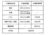
- the water use usage determining unit 13 has a table regarding water usage and water usage time in each usage as shown in FIG. 2, for example.
- the numerical value of this table is an example, Other numerical values may be sufficient and a setting may be changed suitably.
- each item of the water use purpose of the table shown in FIG. 2 is an example, may be another item, and may be changed suitably.
- the water usage determination unit 13 determines that the usage of the water usage is a toilet.
- the water use usage determination part 13 determines that it is continuous use, when water use time is continuous for 30 minutes or more. In this case, the watching server determines that the watched person is in an abnormal state in which the watched person falls down with the tap water, and notifies the watcher of the change.
- the usage of water usage is determined using the water usage and the water usage time obtained from the measured value of the water meter 2. Thereby, the use of water supply can be determined accurately. And since the use of water supply can be determined using an existing water meter, a water usage detection system can be realized with a simple and low-cost configuration.
- the usage can be determined with a certain degree of accuracy without changing the standard for determining the usage of the water supply according to the watched person.
- FIG. 3 is a block diagram showing the overall configuration of the watching system 10 including the water supply usage detection system 1 according to the embodiment of the present invention.
- the watching system 10 includes a water usage detection system 1 and a watching server 3 described later.
- the water usage detection system 1 includes a water usage acquisition unit 11, a water usage calculation unit 12, a water usage determination unit 13, a water usage storage 14, a water usage storage 15, and a communication unit 16. .
- the water usage acquisition unit 11 acquires a pulse signal output from the water meter 2 at regular intervals, converts the pulse signal into a water usage, and outputs the converted signal to the water usage calculation unit 12.
- the water usage amount acquisition unit 11 includes a pulse signal acquisition unit 21, a count unit 22, and a conversion unit 23.
- the pulse signal acquisition unit 21 acquires a pulse signal output from the water meter 2.
- the counting unit 22 is configured to count a certain time.
- the conversion unit 23 converts the pulse signal acquired by the pulse signal acquisition unit 21 within the predetermined time into the amount of water used for every predetermined time counted by the counting unit 22.
- the water usage storage unit 14 is configured by a storage device such as a flash memory.
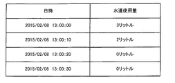
- the water usage amount storage unit 14 stores the water usage amount for each fixed time output from the water usage amount acquisition unit 11. That is, as shown in FIG. 4, the water usage amount storage unit 14 stores a water usage amount for each fixed time in a time series.
- the water usage calculation unit 12 calculates the water usage and the water usage time in the continuous use state based on the water usage for every fixed time stored in the water usage storage unit 14. That is, the water usage calculation part 12 is the continuous water usage state by the same use for the water usage whose water usage is more than predetermined value among the water usage for every fixed time memorize
- the amount of water used and the amount of water used in the continuous water usage state are integrated to obtain the amount of water used and the amount of water used for that purpose.
- the predetermined value is set to a value at which it can be determined that the water supply is continuously used.
- the predetermined value is determined according to the detection performance of the water meter 2, for example. That is, if the pulse signal output from the water meter 2 is every 1 liter, the predetermined value is set to 1 liter.
- the water supply usage determination unit 13 determines the usage of water usage using the water usage and the water usage time obtained by the water usage calculation unit 12. That is, the water usage determination unit 13 has a table as shown in FIG. 2 and uses the water consumption and the water usage time obtained by the table and the water usage calculation unit 12 to determine the usage of the water usage. judge. For example, when the water usage amount obtained by the water usage calculation unit 12 is 15 liters and the water usage time is 5 minutes, the water usage determination unit 13 determines that the usage of the water usage is cooking, hand washing, and face washing. .
- the water supply use storage unit 15 is configured by a storage device such as a flash memory.
- the water usage storage unit 15 stores the usage of water usage determined by the water usage determination unit 13.
- the usage of the water supply is stored in the water supply usage storage unit 15 for each time zone.
- the communication unit 16 transmits the usage of the water supply stored in the water supply usage storage unit 15 to the watching server 3 via the network 4 as water usage data. That is, the communication unit 16 is connected to the network 4 such as the Internet or a dedicated network line by wireless communication such as power saving wireless communication or wired communication.
- the monitoring server 3 receives the water usage data via the network 4 when the water usage data is transmitted from the water usage detection system 1.
- the watching server 3 determines that the change has occurred when the number of times of water use for each use of the water use included in the received water use data is different from the reference number of times that is the reference for the change determination.
- the monitoring server 3 notifies the watching person of the abnormality via the network 4.
- the watching server 3 includes a communication unit 31, a water usage data storage unit 32, a reference number setting unit 33, a change determination unit 34, and a change notification unit 35.
- the communication unit 31 is communicably connected to the network 4.
- the communication unit 31 receives the water usage data from the water usage detection system 1 via the network 4, and when the abnormal notification signal is generated by the abnormal notification unit 35, the abnormal notification signal is transmitted via the network 4. It transmits to the display terminal 5 of the watcher.
- the water usage data storage unit 32 is configured by a storage device such as a hard disk device or a flash memory.
- the water usage data storage unit 32 stores the water usage data received by the communication unit 31.
- the water usage data includes the usage of water usage, the number of times of water usage, the amount of water usage, the time of water usage, and the like.
- the reference number setting unit 33 sets a reference number of times when the abnormality determination unit 34 performs the abnormality determination. Specifically, the reference number setting unit 33 averages the number of times of use in each use of the water supply in the most recent predetermined period among the water use data stored in the water use data storage unit 32, and the average number of times Ask for. Further, the reference number setting unit 33 obtains a standard deviation with respect to the average number of times using the number of times of use, and calculates a reference number of times in consideration of the standard deviation.
- FIG. 5 shows an example of the reference number set by the reference number setting unit 33.
- FIG. 5 shows an example in which the reference number of times is calculated using water supply data for the latest three days.
- the reference number setting unit 33 calculates the average and standard deviation of the number of times of use for three days in each use of bath, laundry, toilet, cooking / hand washing / face washing.
- the reference number setting unit 33 obtains the reference number for each application using the calculated average and standard deviation.
- the reference number setting unit 33 may update the reference number by always using the latest data, or set a value calculated using data of a specific period as the reference number. Also good.
- the reference count is always updated using the latest data, the latest state of the watched person can always be used as a reference. That is, even when the watched person's state fluctuates over a long period of time, it is possible to detect a change in a short period of time without being affected by it. Moreover, since it is not affected by individual differences, it is not necessary to make settings for each watched person.
- the reference number is set using data of a specific period, the reference can always be kept constant even in a state where anomalies are gradually occurring.
- the anomaly determination unit 34 compares the number of uses within a certain period (for example, one day) in each use of water supply stored in the water use data storage unit 32 with the reference number set by the reference number setting unit 33. By doing so, it is determined whether or not an abnormality has occurred.
- the abnormality determination unit 34 determines that an abnormality has occurred in the watched person when the number of times of use of the toilet or bath is zero in each use of the water supply. If the toilet is not used for a day, the watcher may fall down. In addition, when there is no daily bath use, there is a possibility that the watched person falls down or is sick.
- the anomaly determination part 34 is when the frequency
- the anomaly determination unit 34 determines that an anomaly has occurred in the watched person not only by the determination based on the number of times of use as described above, but also when the continuous use with a usage time of 30 minutes or more occurs even once. To do. If continuous use occurs for more than 30 minutes, the watched person may have fallen while using the water supply.
- the anomaly determination unit 34 outputs an anomaly detection signal to the anomaly notification unit 35 when it is determined as an anomaly.
- the anomaly notification unit 35 generates an anomaly notification signal and outputs it to the watcher's display terminal 5 via the communication unit 31 when an anomaly detection signal is output from the anomaly determination unit 34.
- This abnormality notification signal includes the contents and time of the abnormality of the watched person and the watcher's address (ID, e-mail address, etc.).
- the notification method of the watcher to the display terminal 5 by the anomaly notification unit 35 may be any method such as e-mail or a dedicated homepage.
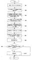
- FIG. 6 is a flowchart showing the operation of the watching system 10.
- FIGS. 1 and 3 are referred to as appropriate.
- the watching method is implemented by operating the watching system 10. Therefore, the description of the watching method in the present embodiment is replaced with the following description of the operation of the watching system 10.
- the operation of the water usage detection system 1 is also explained by the following description of the operation of the monitoring system 10.
- the description of the water usage detection method is also replaced with the following description of the operation of the monitoring system 10.
- the water usage detection system 1 operates.
- the pulse signal acquisition unit 21 of the water usage acquisition unit 11 acquires a pulse signal output from the water meter 2 according to the water usage (step SA1).
- the conversion unit 23 of the water usage acquisition unit 11 calculates the water usage for a certain time (step SA2).
- the water usage calculation unit 12 calculates the water usage and the water usage time in the continuous usage state by using the water usage per fixed time calculated by the water usage acquisition unit 11 (step SA3).
- the calculated water usage amount and water usage time are stored in the water usage amount storage unit 14 (step SA3).
- the water usage determination unit 13 determines the usage of the water usage using the water usage and the water usage time calculated by the water usage calculation unit 12 (step SA4). At this time, the water usage determination unit 13 determines the usage of the water supply from the water usage and the water usage time using a table as shown in FIG. The determination result of the use of water supply by the water supply use determination unit 13 is stored in the water supply use storage unit 15 (step SA4).
- the water usage detection system 1 can determine the usage in continuous water usage using the pulse signal output from the existing water meter 2. Therefore, it is possible to accurately detect the usage of water supply by a simple and low-cost method.
- the usage of water usage detected by the water usage detection system 1 is transmitted to the watching server 3 as water usage data (step SA5).
- the water usage data transmitted to the watching server 3 is received by the communication unit 31 and stored in the water usage data storage unit 32 (step SA6).
- the reference number setting unit 33 uses the water usage data stored in the water usage data storage unit 32 to obtain a reference number for anomaly determination (step SA7). Specifically, the reference number setting unit 33 obtains an average number and a standard deviation from the number of uses in each usage of the water supply in the latest predetermined period, and calculates the reference number.
- the abnormality determination unit 34 uses the reference number set by the reference number setting unit 33 to determine whether the water usage data stored in the water usage data storage unit 32 corresponds to the criterion for the abnormality determination. (Step SA8).
- the criteria for anomaly judgment are whether the number of toilets or baths used within a certain period (for example, one day) is zero among each use of water supply, and the number of uses within a certain period of each use of water supply It is whether it is different from the number of times, or whether the continuous use with a usage time of 30 minutes or more has occurred even once.
- an abnormality determination signal is output from the abnormality determination unit 34 to the abnormality notification unit 35.
- a change is notified to the display terminal 5 of the watcher via the communication unit 31 (step SA9).
- step SA8 if it is determined by the event determination unit 34 that the event does not meet the criteria for event determination (NO in step SA8), this flow is terminated without making an event notification (End).
- step SA1 for obtaining the pulse signal from the water meter 2 corresponds to the water usage amount obtaining step
- the SA3 for obtaining the water usage amount and the water usage time based on the pulse signal obtained from the water meter 2 is calculated for the water usage.
- step SA4 for determining the usage of water supply using the obtained water usage and water usage time corresponds to the water usage determination step, and in the usage of water supply, the water usage data satisfies the criteria for anomaly determination. If there is, step SA9 for notifying the watcher of the change corresponds to the change notification step.
- step SA7 for setting the reference number corresponds to a reference number setting step.
- the configuration of the present embodiment it is possible to determine the amount of water usage and the time of water usage using the pulse signal output from the existing water meter 2, and determine the usage of the water usage from those values. Thereby, the use of water supply can be accurately detected with a simple and low-cost configuration.
- the reference number used for the judgment of anomalies is calculated, so the watched person is always up-to-date. As a reference, it is possible to determine anomalies. Therefore, it is possible to improve the accuracy of the abnormality determination of the watched person.
- the program in the first embodiment of the present invention may be a program that causes a computer to execute steps SA1 to SA9 shown in FIG.
- the CPU Central Processing Unit
- the CPU of the computer functions as the water usage acquisition unit 11, the water usage calculation unit 12, and the water usage determination unit 13 of the water usage detection system 1, and performs processing.
- the CPU of another computer functions as the reference number setting unit 33, the abnormality determination unit 34, and the abnormality notification unit 35 of the watching server 3, and performs processing.
- the water usage storage unit 14 and the water usage storage unit 15 store the data files constituting them in a storage device included in the computer, or a recording medium on which the data files are stored. Is implemented in a reading device connected to a computer.
- the water usage data storage unit 32 is also connected to a computer by storing data files constituting the data files in a storage device included in the computer or by storing a recording medium storing the data files. This is realized by mounting on a reading device.
- FIG. 7 is a block diagram illustrating an example of a computer that implements the watching system 10 according to the embodiment of the present invention.
- achieves the watch server 10 have the same structure, below, the computer which implement
- the computer 110 includes a CPU 111, a main memory 112, a storage device 113, an input interface 114, a display controller 115, a data reader / writer 116, and a communication interface 117. These units are connected to each other via a bus 121 so that data communication is possible.
- the CPU 111 performs various operations by expanding the program (code) in the present embodiment stored in the storage device 113 in the main memory 112 and executing them in a predetermined order.
- the main memory 112 is typically a volatile storage device such as a DRAM (Dynamic Random Access Memory).
- the program in the present embodiment is provided in a state of being stored in the computer-readable recording medium 120. Note that the program in the present embodiment may be distributed on the Internet connected via the communication interface 117.
- the storage device 113 includes a hard disk drive and a semiconductor storage device such as a flash memory.
- the input interface 114 mediates data transmission between the CPU 111 and an input device 118 such as a keyboard and a mouse.
- the display controller 115 is connected to the display device 119 and controls display on the display device 119.
- the data reader / writer 116 mediates data transmission between the CPU 111 and the recording medium 120, and reads a program from the recording medium 120 and writes a processing result in the computer 110 to the recording medium 120.
- the communication interface 117 mediates data transmission between the CPU 111 and another computer.
- the recording medium 120 include general-purpose semiconductor storage devices such as CF (Compact Flash (registered trademark)) and SD (Secure Digital), magnetic storage media such as a flexible disk (CD), or CD- An optical storage medium such as ROM (Compact Disk Only Memory) may be used.
- CF Compact Flash
- SD Secure Digital
- magnetic storage media such as a flexible disk (CD)
- CD- An optical storage medium such as ROM (Compact Disk Only Memory) may be used.
- FIG. 8 the structure of the watching system 100 containing the water supply use detection system 101 which concerns on Embodiment 2 of this invention is shown.
- the monitoring system 100 of this embodiment differs from the monitoring system 1 of the first embodiment only in the configuration of the water usage detection system 101. Therefore, in the following description, the configuration of the water usage detection system 101 will be mainly described, and the same reference numerals are given to the same configurations as those in the first embodiment, and the description will be omitted.
- the water usage detection system 101 determines the usage of the water supply in consideration of whether the sewage has flowed in addition to the water usage and the water usage time.
- the water usage detection system 101 includes a water usage acquisition unit 11, a water usage storage 14, a water usage calculator 12, a water usage determination unit 102, a water usage storage 15, a communication Unit 16, sewage information acquisition unit 103, and sewage information storage unit 104.
- the sewage information acquisition unit 103 acquires a signal (information regarding use of sewage) output from the sewage measurement unit 6 for detecting the presence or absence of a sewage flow.
- the sewage measuring unit 6 is, for example, a sound sensor that is attached to a sewage basin where sewage collects and detects the sound of sewage flowing into the sewage basin. Thus, the use of the whole sewage can be easily detected by attaching the sewage measuring unit 6 to the sewage basin.
- the sewage information acquisition unit 103 is configured to detect that there is use of sewage when the sewage measurement unit 6 detects a sound volume above a certain level, and to generate and output a sewage use signal.
- the sewage use signal includes information about the time when the sewage sound is detected by the sewage measurement unit 6 as well as information that the sewage is used.
- the sewage information storage unit 104 is configured by a storage device such as a flash memory.
- the sewage information storage unit 104 stores the sewage use signal output from the sewage information acquisition unit 103.
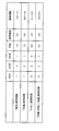
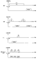
- the water usage determination unit 102 uses the water usage and the water usage time output from the water usage calculation unit 12 having the same configuration as in the first embodiment, and the sewage usage signal stored in the sewage information storage unit 104. Determine the usage of water supply. Specifically, the water usage determination unit 102 determines the usage of water usage based on the amount of water used, the amount of water used, whether or not sewage is used, and the timing, using the criteria shown in FIG.
- the standard shown in FIG. 9 is determined by the relationship between the water usage amount, the water usage time, and the sewage usage at the time of general water usage shown in FIG. That is, as shown in FIG. 10, when the use of water supply is a bath, after using a large amount of tap water, there is use of sewage, and when the use of water supply is washing, washing and rinsing are performed. Use sewage after using tap water. In addition, if the usage of the water supply is a toilet, there is a small amount of tap water after the use of sewage. If the usage of the water supply is cooking, washing hands, or washing the face, a small amount of tap water is used. In addition to frequent use, there is almost simultaneous use of sewage.
- the water use usage determining unit 102 determines the usage of the water supply in consideration of not only the amount of water used and the time of water usage but also the presence / absence of sewage and the timing thereof. Therefore, compared with the case where the usage of water supply is determined in consideration of the amount of water usage and the usage time of water as in the first embodiment, the usage of water usage can be determined with higher accuracy. Therefore, it is possible to detect an abnormality of the watched person with higher accuracy by using the determination result in the system.
- the configuration of the watching server 3 is the same as the configuration of the first embodiment, and a description thereof will be omitted.
- FIG. 11 is a flowchart showing the operation of the watching system 100.
- FIGS. 1, 3, and 8 are referred to as appropriate.
- the monitoring method is similarly implemented by operating the monitoring system 100. Therefore, the description of the watching method in the present embodiment is replaced with the following description of the operation of the watching system 100.
- steps SB1 to SB3 and SB6 to SB10 are the same as steps SA1 to SA3 and SA5 to SA9 in FIG. In the following description, only parts different from the flow shown in FIG. 6 of the first embodiment will be described.
- step SB4 the sewage information acquisition unit 103 acquires a signal output from the sewage measurement unit 6, and generates and outputs a sewage use signal.
- the sewage use signal is stored in the sewage information storage unit 104.
- the water usage determination unit 102 determines the usage of the water usage using the water usage and the water usage time calculated in step SB3 and the sewage usage signal obtained in step SB4. Specifically, the water-use usage determining unit 102 determines the usage of water-use based on the water usage, the water usage time, and the sewage usage based on the criteria shown in FIG.
- step SB4 for obtaining a signal output from the sewage measurement unit corresponds to a sewage information obtaining step.
- a water usage detection system that detects the usage of water based on the usage status of water, A water usage acquisition unit that acquires information on water usage from a water usage measurement unit for measuring water usage; Based on the information on the water usage acquired by the water usage acquisition unit, the water usage calculation unit for obtaining the water usage and the water usage time, A water usage detection system, comprising: a water usage determination unit that determines a usage of water usage using a water usage and a water usage time obtained by the water usage calculation unit.
- Appendix 2 In the water usage detection system described in Appendix 1, A sewage information acquisition unit for acquiring information on the use of sewage output from the sewage measurement unit for measuring the presence or absence of sewage use; The water use usage determination unit determines the usage of water supply by considering the information on the use of sewage acquired by the sewage information acquisition unit in addition to the water usage and the water usage time. Detection system.
- the water usage measuring unit is a water meter
- the said water usage amount acquisition part is a water usage detection system which acquires the signal output from a water meter as information regarding the said water usage.
- Appendix 4 A monitoring system that detects changes in a watched person, Water usage detection system according to appendix 1, A monitoring system comprising a change notification unit that notifies a watcher of a change when the number of uses of the water supply in a certain period is different from a reference number in the use of the water supply determined by the water supply use determination unit.
- a reference number setting unit for setting the reference number In the monitoring system described in Appendix 4, A reference number setting unit for setting the reference number; The reference number of times setting unit detects the number of times of water supply use in the usage of water supply determined by the water supply usage determination unit within a predetermined period, and considers the average number of times and the standard deviation obtained based on the detection result. A watch system that sets the standard number of times.
- a water usage detection method for detecting the usage of water based on the usage status of water A water usage acquisition step for acquiring information on water usage from a water usage measuring unit for measuring water usage; Based on the information on the water usage acquired by the water usage acquisition step, the water usage calculation step for obtaining the water usage and the water usage time, A water usage detection method comprising: a water usage determination step of determining a usage of water usage using the water usage and the water usage time obtained in the water usage calculation step.
- a sewage information acquisition step for acquiring information on the use of sewage output from the sewage measurement unit for measuring the presence or absence of use of sewage In the water use usage determining step, in addition to the water usage and the water usage time, the water usage is determined by considering information on the use of sewage obtained in the sewage information obtaining step. Detection method.
- the water usage measuring unit is a water meter
- the water usage detection step is a water usage detection method of acquiring a signal output from a water meter as information relating to the water usage.
- a monitoring method for detecting an abnormality of a watchee A water usage acquisition step for acquiring information on water usage from a water usage measuring unit for measuring water usage; Based on the information on the water usage acquired by the water usage acquisition step, the water usage calculation step for obtaining the water usage and the water usage time, Using the water usage amount and the water usage time determined in the water usage calculation step, the water usage determination step for determining the usage of the water usage, A monitoring method comprising a change notification step of notifying a watcher of a change when the number of water uses within a certain period is different from a reference number in the use of the water supply determined in the water use determination step.
- the reference number of times setting step detects the number of times of water use in the usage of the water supply determined in the water usage determination step within a predetermined period, and considers the average number of times and the standard deviation obtained based on the detection result.
- a watch method that sets the reference count.
- a water usage acquisition step for acquiring information on water usage from a water usage measuring unit for measuring water usage; Based on the information on the water usage acquired by the water usage acquisition step, the water usage calculation step for obtaining the water usage and the water usage time, A computer-readable recording medium on which a program is recorded, including a command for executing a water usage determination step for determining a usage of water usage using the water usage and the water usage time obtained in the water usage calculation step.
- the water usage measuring unit is a water meter
- the said water usage amount acquisition step is a computer-readable recording medium which acquires the signal output from a water meter as information regarding the said water usage.
- the program is stored in the computer.
- the reference number of times setting step detects the number of times of water use in the usage of the water supply determined in the water usage determination step within a predetermined period, and considers the average number of times and the standard deviation obtained based on the detection result.
- the present invention can be used in a water usage detection system for detecting usage in accordance with the usage status of water.
Landscapes
- Business, Economics & Management (AREA)
- Health & Medical Sciences (AREA)
- Physics & Mathematics (AREA)
- General Physics & Mathematics (AREA)
- Engineering & Computer Science (AREA)
- General Health & Medical Sciences (AREA)
- Emergency Management (AREA)
- Economics (AREA)
- Primary Health Care (AREA)
- Public Health (AREA)
- General Business, Economics & Management (AREA)
- Gerontology & Geriatric Medicine (AREA)
- Biomedical Technology (AREA)
- Marketing (AREA)
- Human Resources & Organizations (AREA)
- Strategic Management (AREA)
- Tourism & Hospitality (AREA)
- Water Supply & Treatment (AREA)
- Theoretical Computer Science (AREA)
- Fluid Mechanics (AREA)
- Medical Informatics (AREA)
- Epidemiology (AREA)
- Psychiatry (AREA)
- Psychology (AREA)
- Social Psychology (AREA)
- Measuring Volume Flow (AREA)
- Emergency Alarm Devices (AREA)
- Alarm Systems (AREA)
- Management, Administration, Business Operations System, And Electronic Commerce (AREA)
- Medical Treatment And Welfare Office Work (AREA)
Abstract
Description
以下、本発明の実施形態1に係る水道使用検知システム、見守りシステム、水道使用検知方法、見守り方法及びプログラムについて、図1から図7を参照しながら説明する。
図8に、本発明の実施形態2に係る水道使用検知システム101を含む見守りシステム100の構成を示す。この実施形態の見守りシステム100は、実施形態1の見守りシステム1とは、水道使用検知システム101の構成のみが異なる。よって、以下の説明では、主に水道使用検知システム101の構成について説明し、実施形態1と同様の構成についは同一の符号を付して説明を省略する。
水道の使用状況に基づいて水道使用の用途を検知する水道使用検知システムであって、
水道使用量を計測するための水道使用量計測部から水道使用量に関する情報を取得する水道使用量取得部と、
前記水道使用量取得部によって取得された水道使用量に関する情報に基づいて、水道使用量及び水道使用時間を求める水道使用算出部と、
前記水道使用算出部で求められた水道使用量及び水道使用時間を用いて、水道使用の用途を判定する水道用途判定部とを備える、水道使用検知システム。
付記1に記載の水道使用検知システムにおいて、
下水の使用の有無を計測するための下水計測部から出力される下水の使用に関する情報を取得する下水情報取得部をさらに備え、
前記水道用途判定部は、前記水道使用量及び前記水道使用時間に加えて、前記下水情報取得部によって取得された下水の使用に関する情報も考慮することにより、水道使用の用途を判定する、水道使用検知システム。
付記1に記載の水道使用検知システムにおいて、
前記水道使用量計測部は、水道メータであり、
前記水道使用量取得部は、水道メータから出力される信号を前記水道使用量に関する情報として取得する、水道使用検知システム。
被見守り者の異変を検知する見守りシステムであって、
付記1に記載の水道使用検知システムと、
前記水道用途判定部によって判定された水道使用の用途において、一定期間内の水道使用回数が基準回数と異なる場合に、見守り者に対して異変を通知する異変通知部とを備える、見守りシステム。
付記4に記載の見守りシステムにおいて、
前記基準回数を設定するための基準回数設定部をさらに備え、
前記基準回数設定部は、前記水道用途判定部によって判定された水道使用の用途における水道使用回数を所定期間内で検出し、その検出結果に基づいて求めた平均回数及び標準偏差を考慮して前記基準回数を設定する、見守りシステム。
水道の使用状況に基づいて水道使用の用途を検知する水道使用検知方法であって、
水道使用量を計測するための水道使用量計測部から水道使用量に関する情報を取得する水道使用量取得ステップと、
前記水道使用量取得ステップによって取得された水道使用量に関する情報に基づいて、水道使用量及び水道使用時間を求める水道使用算出ステップと、
前記水道使用算出ステップで求められた水道使用量及び水道使用時間を用いて、水道使用の用途を判定する水道用途判定ステップとを備える、水道使用検知方法。
付記6に記載の水道使用検知方法において、
下水の使用の有無を計測するための下水計測部から出力される下水の使用に関する情報を取得する下水情報取得ステップをさらに備え、
前記水道用途判定ステップでは、前記水道使用量及び前記水道使用時間に加えて、前記下水情報取得ステップによって取得された下水の使用に関する情報も考慮することにより、水道使用の用途を判定する、水道使用検知方法。
付記6に記載の水道使用検知方法において、
前記水道使用量計測部は、水道メータであり、
前記水道使用量取得ステップは、水道メータから出力される信号を前記水道使用量に関する情報として取得する、水道使用検知方法。
被見守り者の異変を検知する見守り方法であって、
水道使用量を計測するための水道使用量計測部から水道使用量に関する情報を取得する水道使用量取得ステップと、
前記水道使用量取得ステップによって取得された水道使用量に関する情報に基づいて、水道使用量及び水道使用時間を求める水道使用算出ステップと、
前記水道使用算出ステップで求められた水道使用量及び水道使用時間を用いて、水道使用の用途を判定する水道用途判定ステップと、
前記水道用途判定ステップによって判定された水道使用の用途において、一定期間内の水道使用回数が基準回数と異なる場合に、見守り者に対して異変を通知する異変通知ステップとを備える、見守り方法。
付記9に記載の見守り方法において、
前記基準回数を設定するための基準回数設定ステップをさらに備え、
前記基準回数設定ステップは、前記水道用途判定ステップによって判定された水道使用の用途における水道使用回数を所定期間内で検出し、その検出結果に基づいて求めた平均回数及び標準偏差を考慮して前記基準回数を設定する、見守り方法。
コンピュータに、
水道使用量を計測するための水道使用量計測部から水道使用量に関する情報を取得する水道使用量取得ステップと、
前記水道使用量取得ステップによって取得された水道使用量に関する情報に基づいて、水道使用量及び水道使用時間を求める水道使用算出ステップと、
前記水道使用算出ステップで求められた水道使用量及び水道使用時間を用いて、水道使用の用途を判定する水道用途判定ステップとを実行させる命令を含む、プログラムを記録したコンピュータ読み取り可能な記録媒体。
付記11に記載のコンピュータ読み取り可能な記録媒体において、
前記プログラムが、前記コンピュータに、
下水の使用の有無を計測する下水計測部から出力される下水の使用に関する情報を取得する下水情報取得ステップをさらに実行させる命令を含み、
前記水道用途判定ステップでは、前記水道使用量及び前記水道使用時間に加えて、前記下水情報取得ステップによって取得された下水の使用に関する情報も考慮することにより、水道使用の用途を判定する、コンピュータ読み取り可能な記録媒体。
付記11に記載のコンピュータ読み取り可能な記録媒体において、
前記水道使用量計測部は、水道メータであり、
前記水道使用量取得ステップは、水道メータから出力される信号を前記水道使用量に関する情報として取得する、コンピュータ読み取り可能な記録媒体。
付記11に記載のコンピュータ読み取り可能な記録媒体において、
前記プログラムが、前記コンピュータに、
前記水道用途判定ステップによって判定された水道使用の用途において、一定期間内の水道使用回数が基準回数と異なる場合に、見守り者に対して異変を通知する異変通知ステップをさらに実行させる命令を含む、コンピュータ読み取り可能な記録媒体。
付記14に記載のコンピュータ読み取り可能な記録媒体において、
前記プログラムが、前記コンピュータに、
前記基準回数を設定するための基準回数設定ステップをさらに実行させる命令を含み、
前記基準回数設定ステップは、前記水道用途判定ステップによって判定された水道使用の用途における水道使用回数を所定期間内で検出し、その検出結果に基づいて求めた平均回数及び標準偏差を考慮して前記基準回数を設定する、コンピュータ読み取り可能な記録媒体。
2 水道メータ(水道使用量計測部)
3 見守りサーバ
4 ネットワーク
5 表示端末
6 下水流量計測部
10、100 見守りシステム
11 水道使用量取得部
12 水道使用算出部
13、102 水道用途判定部
14 水道使用量記憶部
15 水道用途記憶部
16 通信部
21 パルス信号取得部
22 カウント部
23 換算部
31 通信部
32 水道使用データ記憶部
33 基準回数設定部
34 異変判定部
35 異変通知部
103 下水情報取得部
104 下水情報記憶部
110 コンピュータ
111 CPU
112 メインメモリ
113 記憶装置
114 入力インターフェイス
115 表示コントローラ
116 データリーダ/ライタ
117 通信インターフェイス
118 入力機器
119 ディスプレイ装置
120 記録媒体
121 バス
Claims (15)
- 水道の使用状況に基づいて水道使用の用途を検知する水道使用検知システムであって、
水道使用量を計測するための水道使用量計測部から水道使用量に関する情報を取得する水道使用量取得部と、
前記水道使用量取得部によって取得された水道使用量に関する情報に基づいて、水道使用量及び水道使用時間を求める水道使用算出部と、
前記水道使用算出部で求められた水道使用量及び水道使用時間を用いて、水道使用の用途を判定する水道用途判定部とを備える、水道使用検知システム。 - 請求項1に記載の水道使用検知システムにおいて、
下水の使用の有無を計測するための下水計測部から出力される下水の使用に関する情報を取得する下水情報取得部をさらに備え、
前記水道用途判定部は、前記水道使用量及び前記水道使用時間に加えて、前記下水情報取得部によって取得された下水の使用に関する情報も考慮することにより、水道使用の用途を判定する、水道使用検知システム。 - 請求項1または2に記載の水道使用検知システムにおいて、
前記水道使用量計測部は、水道メータであり、
前記水道使用量取得部は、水道メータから出力される信号を前記水道使用量に関する情報として取得する、水道使用検知システム。 - 被見守り者の異変を検知する見守りシステムであって、
請求項1から3のいずれか一つに記載の水道使用検知システムと、
前記水道用途判定部によって判定された水道使用の用途において、一定期間内の水道使用回数が基準回数と異なる場合に、見守り者に対して異変を通知する異変通知部とを備える、見守りシステム。 - 請求項4に記載の見守りシステムにおいて、
前記基準回数を設定するための基準回数設定部をさらに備え、
前記基準回数設定部は、前記水道用途判定部によって判定された水道使用の用途における水道使用回数を所定期間内で検出し、その検出結果に基づいて求めた平均回数及び標準偏差を考慮して前記基準回数を設定する、見守りシステム。 - 水道の使用状況に基づいて水道使用の用途を検知する水道使用検知方法であって、
水道使用量を計測するための水道使用量計測部から水道使用量に関する情報を取得する水道使用量取得ステップと、
前記水道使用量取得ステップによって取得された水道使用量に関する情報に基づいて、水道使用量及び水道使用時間を求める水道使用算出ステップと、
前記水道使用算出ステップで求められた水道使用量及び水道使用時間を用いて、水道使用の用途を判定する水道用途判定ステップとを備える、水道使用検知方法。 - 請求項6に記載の水道使用検知方法において、
下水の使用の有無を計測するための下水計測部から出力される下水の使用に関する情報を取得する下水情報取得ステップをさらに備え、
前記水道用途判定ステップでは、前記水道使用量及び前記水道使用時間に加えて、前記下水情報取得ステップによって取得された下水の使用に関する情報も考慮することにより、水道使用の用途を判定する、水道使用検知方法。 - 請求項6または7に記載の水道使用検知方法において、
前記水道使用量計測部は、水道メータであり、
前記水道使用量取得ステップは、水道メータから出力される信号を前記水道使用量に関する情報として取得する、水道使用検知方法。 - 被見守り者の異変を検知する見守り方法であって、
水道使用量を計測するための水道使用量計測部から水道使用量に関する情報を取得する水道使用量取得ステップと、
前記水道使用量取得ステップによって取得された水道使用量に関する情報に基づいて、水道使用量及び水道使用時間を求める水道使用算出ステップと、
前記水道使用算出ステップで求められた水道使用量及び水道使用時間を用いて、水道使用の用途を判定する水道用途判定ステップと、
前記水道用途判定ステップによって判定された水道使用の用途において、一定期間内の水道使用回数が基準回数と異なる場合に、見守り者に対して異変を通知する異変通知ステップとを備える、見守り方法。 - 請求項9に記載の見守り方法において、
前記基準回数を設定するための基準回数設定ステップをさらに備え、
前記基準回数設定ステップは、前記水道用途判定ステップによって判定された水道使用の用途における水道使用回数を所定期間内で検出し、その検出結果に基づいて求めた平均回数及び標準偏差を考慮して前記基準回数を設定する、見守り方法。 - コンピュータに、
水道使用量を計測するための水道使用量計測部から水道使用量に関する情報を取得する水道使用量取得ステップと、
前記水道使用量取得ステップによって取得された水道使用量に関する情報に基づいて、水道使用量及び水道使用時間を求める水道使用算出ステップと、
前記水道使用算出ステップで求められた水道使用量及び水道使用時間を用いて、水道使用の用途を判定する水道用途判定ステップとを実行させる命令を含む、プログラムを記録したコンピュータ読み取り可能な記録媒体。 - 請求項11に記載のコンピュータ読み取り可能な記録媒体において、
前記プログラムが、前記コンピュータに、
下水の使用の有無を計測する下水計測部から出力される下水の使用に関する情報を取得する下水情報取得ステップをさらに実行させる命令を含み、
前記水道用途判定ステップでは、前記水道使用量及び前記水道使用時間に加えて、前記下水情報取得ステップによって取得された下水の使用に関する情報も考慮することにより、水道使用の用途を判定する、コンピュータ読み取り可能な記録媒体。 - 請求項11または12に記載のコンピュータ読み取り可能な記録媒体において、
前記水道使用量計測部は、水道メータであり、
前記水道使用量取得ステップは、水道メータから出力される信号を前記水道使用量に関する情報として取得する、コンピュータ読み取り可能な記録媒体。 - 請求項11から13のいずれか一つに記載のコンピュータ読み取り可能な記録媒体において、
前記プログラムが、前記コンピュータに、
前記水道用途判定ステップによって判定された水道使用の用途において、一定期間内の水道使用回数が基準回数と異なる場合に、見守り者に対して異変を通知する異変通知ステップをさらに実行させる命令を含む、コンピュータ読み取り可能な記録媒体。 - 請求項14に記載のコンピュータ読み取り可能な記録媒体において、
前記プログラムが、前記コンピュータに、
前記基準回数を設定するための基準回数設定ステップをさらに実行させる命令を含み、
前記基準回数設定ステップは、前記水道用途判定ステップによって判定された水道使用の用途における水道使用回数を所定期間内で検出し、その検出結果に基づいて求めた平均回数及び標準偏差を考慮して前記基準回数を設定する、コンピュータ読み取り可能な記録媒体。
Priority Applications (4)
| Application Number | Priority Date | Filing Date | Title |
|---|---|---|---|
| KR1020177031211A KR20170132274A (ko) | 2015-03-31 | 2016-03-30 | 수도 사용 검출 시스템, 이를 사용하는 감시 시스템, 수도 사용 검출 방법, 감시 방법, 및 컴퓨터 판독가능 기록 매체 |
| US15/562,100 US20180075726A1 (en) | 2015-03-31 | 2016-03-30 | Tap water use detection system, watching system using same, tap water use detection method, watching method, and computer-readable recording medium |
| CN201680020224.6A CN107430753B (zh) | 2015-03-31 | 2016-03-30 | 自来水使用检测系统和方法、观察系统和方法及计算机可读记录介质 |
| JP2017510093A JP6440223B2 (ja) | 2015-03-31 | 2016-03-30 | 水道使用検知システム、それを用いた見守りシステム、水道使用検知方法、見守り方法及びプログラム |
Applications Claiming Priority (2)
| Application Number | Priority Date | Filing Date | Title |
|---|---|---|---|
| JP2015071275 | 2015-03-31 | ||
| JP2015-071275 | 2015-03-31 |
Publications (1)
| Publication Number | Publication Date |
|---|---|
| WO2016159065A1 true WO2016159065A1 (ja) | 2016-10-06 |
Family
ID=57004376
Family Applications (1)
| Application Number | Title | Priority Date | Filing Date |
|---|---|---|---|
| PCT/JP2016/060364 Ceased WO2016159065A1 (ja) | 2015-03-31 | 2016-03-30 | 水道使用検知システム、それを用いた見守りシステム、水道使用検知方法、見守り方法及びコンピュータ読み取り可能な記録媒体 |
Country Status (5)
| Country | Link |
|---|---|
| US (1) | US20180075726A1 (ja) |
| JP (1) | JP6440223B2 (ja) |
| KR (1) | KR20170132274A (ja) |
| CN (1) | CN107430753B (ja) |
| WO (1) | WO2016159065A1 (ja) |
Cited By (2)
| Publication number | Priority date | Publication date | Assignee | Title |
|---|---|---|---|---|
| CN111033587A (zh) * | 2017-08-16 | 2020-04-17 | 卡罗马工业有限公司 | 被动护理控制方法和相关联的系统 |
| WO2025197380A1 (ja) * | 2024-03-22 | 2025-09-25 | パナソニックIpマネジメント株式会社 | 異常検知システム |
Families Citing this family (3)
| Publication number | Priority date | Publication date | Assignee | Title |
|---|---|---|---|---|
| CN108414042B (zh) * | 2018-03-07 | 2021-02-23 | 佛山市顺德区美的饮水机制造有限公司 | 取水量控制方法、取水量控制系统和饮水装置 |
| CN108961677A (zh) * | 2018-08-13 | 2018-12-07 | 吉林大学 | 基于水电量分布的空巢老人生活监护系统 |
| CN113267229B (zh) * | 2021-05-31 | 2022-02-01 | 中国水利水电科学研究院 | 一种家庭智能用水监测系统及其监测方法 |
Citations (3)
| Publication number | Priority date | Publication date | Assignee | Title |
|---|---|---|---|---|
| JP2006134155A (ja) * | 2004-11-08 | 2006-05-25 | Cij Hokuden:Kk | 生活行動監視装置およびその方法 |
| JP2013020574A (ja) * | 2011-07-14 | 2013-01-31 | Cosmo Life Kk | 住宅状態確認システム |
| JP2014232461A (ja) * | 2013-05-30 | 2014-12-11 | 株式会社日立製作所 | 水需要量計測見守りサービス装置 |
Family Cites Families (6)
| Publication number | Priority date | Publication date | Assignee | Title |
|---|---|---|---|---|
| TW385436B (en) * | 1997-12-12 | 2000-03-21 | Toshiba Corp | Digital recording system using variable recording rate |
| JP4787200B2 (ja) * | 2007-04-18 | 2011-10-05 | 東芝テック株式会社 | ストアコンピュータ及びコンピュータプログラム |
| WO2009125627A1 (ja) * | 2008-04-11 | 2009-10-15 | 三菱電機株式会社 | 機器状態検出装置及び機器状態検出方法並びに生活者異常検知装置、生活者異常検知システム及び生活者異常検知方法 |
| US20120226136A1 (en) * | 2011-03-04 | 2012-09-06 | The Chinese University Of Hong Kong | Methods and devices of detection, grading, monitoring, and follow-up of fibrosis |
| JP5279877B2 (ja) * | 2011-07-19 | 2013-09-04 | 三菱電機株式会社 | トイレ使用検出システム、トイレ使用検出装置及び安否確認システム |
| US9429453B1 (en) * | 2015-03-24 | 2016-08-30 | Symmons Industries, Inc. | Method and system for managing water usage |
-
2016
- 2016-03-30 JP JP2017510093A patent/JP6440223B2/ja active Active
- 2016-03-30 WO PCT/JP2016/060364 patent/WO2016159065A1/ja not_active Ceased
- 2016-03-30 US US15/562,100 patent/US20180075726A1/en not_active Abandoned
- 2016-03-30 KR KR1020177031211A patent/KR20170132274A/ko not_active Ceased
- 2016-03-30 CN CN201680020224.6A patent/CN107430753B/zh not_active Expired - Fee Related
Patent Citations (3)
| Publication number | Priority date | Publication date | Assignee | Title |
|---|---|---|---|---|
| JP2006134155A (ja) * | 2004-11-08 | 2006-05-25 | Cij Hokuden:Kk | 生活行動監視装置およびその方法 |
| JP2013020574A (ja) * | 2011-07-14 | 2013-01-31 | Cosmo Life Kk | 住宅状態確認システム |
| JP2014232461A (ja) * | 2013-05-30 | 2014-12-11 | 株式会社日立製作所 | 水需要量計測見守りサービス装置 |
Cited By (2)
| Publication number | Priority date | Publication date | Assignee | Title |
|---|---|---|---|---|
| CN111033587A (zh) * | 2017-08-16 | 2020-04-17 | 卡罗马工业有限公司 | 被动护理控制方法和相关联的系统 |
| WO2025197380A1 (ja) * | 2024-03-22 | 2025-09-25 | パナソニックIpマネジメント株式会社 | 異常検知システム |
Also Published As
| Publication number | Publication date |
|---|---|
| JP6440223B2 (ja) | 2018-12-19 |
| US20180075726A1 (en) | 2018-03-15 |
| KR20170132274A (ko) | 2017-12-01 |
| JPWO2016159065A1 (ja) | 2018-03-01 |
| CN107430753A (zh) | 2017-12-01 |
| CN107430753B (zh) | 2021-08-13 |
Similar Documents
| Publication | Publication Date | Title |
|---|---|---|
| JP6440223B2 (ja) | 水道使用検知システム、それを用いた見守りシステム、水道使用検知方法、見守り方法及びプログラム | |
| JP6579638B2 (ja) | 水道使用検知システム、それを用いた見守りシステム、水道使用検知方法、見守り方法およびプログラム | |
| EP2901226B1 (en) | Process variable measurement noise diagnostic | |
| US20130179095A1 (en) | Monitoring water consumption | |
| JPWO2015136839A1 (ja) | 生活行動推定装置、およびプログラム | |
| US10748415B2 (en) | Method for sensor maintenance of redundant sensor loops | |
| JP2019148482A (ja) | 水環境センシング装置 | |
| JP2018506026A (ja) | 環境センサ及び環境パラメータの測定及び予測方法 | |
| CN117932440A (zh) | 数据机房温湿度监测方法、系统、计算机设备及存储介质 | |
| JP5558520B2 (ja) | 状態判定装置、状態判定システム、状態判定方法及びプログラム | |
| KR101342691B1 (ko) | 유량계 원격 검침 장치 및 이를 이용한 유량계 고장 판단장치 및 방법 | |
| WO2016174958A1 (ja) | 漏水発生位置推定装置、システムおよび方法 | |
| EP4063983B1 (en) | Field device, measurement method, and non-transitory computer readable medium | |
| KR101092734B1 (ko) | 통합검침시스템을 이용한 수용가 관리 시스템 및 관리 방법 | |
| JP2012190294A (ja) | 単身者世帯の単身者見守りシステム | |
| KR20160026492A (ko) | 시계열 분석 기반의 신뢰 구간 추정을 이용한 이상 감지 방법 | |
| JP4962571B2 (ja) | 遠隔監視装置 | |
| JP6659056B2 (ja) | 看視システム | |
| JP6740529B2 (ja) | 健康状態推定システム、健康状態推定装置、健康状態推定方法、およびプログラム | |
| JP2016093098A (ja) | 電力使用量管理装置およびプログラム | |
| CN112991698B (zh) | 一种基于二次供水设备的泵房健康度检测方法及系统 | |
| JP2017049142A (ja) | 計量メータの状態変化検出装置及びプログラム | |
| US20140203949A1 (en) | Method and system for automatic residual consumption | |
| JP2022147117A (ja) | 見守りシステムおよびその制御方法 | |
| JP2013210799A (ja) | 生活状況報知システム |
Legal Events
| Date | Code | Title | Description |
|---|---|---|---|
| 121 | Ep: the epo has been informed by wipo that ep was designated in this application |
Ref document number: 16772946 Country of ref document: EP Kind code of ref document: A1 |
|
| WWE | Wipo information: entry into national phase |
Ref document number: 15562100 Country of ref document: US |
|
| ENP | Entry into the national phase |
Ref document number: 2017510093 Country of ref document: JP Kind code of ref document: A |
|
| NENP | Non-entry into the national phase |
Ref country code: DE |
|
| ENP | Entry into the national phase |
Ref document number: 20177031211 Country of ref document: KR Kind code of ref document: A |
|
| 122 | Ep: pct application non-entry in european phase |
Ref document number: 16772946 Country of ref document: EP Kind code of ref document: A1 |