WO2016158937A1 - Capuchon - Google Patents
Capuchon Download PDFInfo
- Publication number
- WO2016158937A1 WO2016158937A1 PCT/JP2016/060088 JP2016060088W WO2016158937A1 WO 2016158937 A1 WO2016158937 A1 WO 2016158937A1 JP 2016060088 W JP2016060088 W JP 2016060088W WO 2016158937 A1 WO2016158937 A1 WO 2016158937A1
- Authority
- WO
- WIPO (PCT)
- Prior art keywords
- cap
- female connector
- tubular portion
- connector
- peripheral surface
- Prior art date
Links
Images


Classifications
-
- A—HUMAN NECESSITIES
- A61—MEDICAL OR VETERINARY SCIENCE; HYGIENE
- A61M—DEVICES FOR INTRODUCING MEDIA INTO, OR ONTO, THE BODY; DEVICES FOR TRANSDUCING BODY MEDIA OR FOR TAKING MEDIA FROM THE BODY; DEVICES FOR PRODUCING OR ENDING SLEEP OR STUPOR
- A61M39/00—Tubes, tube connectors, tube couplings, valves, access sites or the like, specially adapted for medical use
- A61M39/02—Access sites
-
- A—HUMAN NECESSITIES
- A61—MEDICAL OR VETERINARY SCIENCE; HYGIENE
- A61M—DEVICES FOR INTRODUCING MEDIA INTO, OR ONTO, THE BODY; DEVICES FOR TRANSDUCING BODY MEDIA OR FOR TAKING MEDIA FROM THE BODY; DEVICES FOR PRODUCING OR ENDING SLEEP OR STUPOR
- A61M39/00—Tubes, tube connectors, tube couplings, valves, access sites or the like, specially adapted for medical use
- A61M39/20—Closure caps or plugs for connectors or open ends of tubes
Definitions
- the present invention relates to a female connector cap that is detachably attached to the female connector.
- the present invention relates to a cap that can be attached to the female connector and used preferably when performing a priming operation for introducing a liquid material into a tube having a female connector at the downstream end.
- Enteral nutrition is known as a method of administering liquids containing nutrients and drugs to patients who are unable to take their meals from their mouths.
- a catheter is placed in a patient while inserted from the outside of the body into the digestive tract (for example, the stomach).
- Known catheters include a nasal catheter that is inserted from the patient's nose, a PEG (Percutaneous Endoscopic Gastrostomy) catheter that is inserted into a gastric fistula formed on the patient's abdomen, and the like.
- a liquid such as a nutrient, liquid food (commonly referred to as “enteral nutrient”), or a drug is administered to a patient via a catheter.
- a connector (hereinafter referred to as “container-side connector”) provided at the downstream end of a tube connected to a container storing the liquid substance, and an upstream of a catheter placed in the patient
- a connector provided at the side end (hereinafter referred to as “patient-side connector”) is connected.
- a male connector has been used as a container-side connector
- a female connector has been used as a patient-side connector (see, for example, Patent Document 1).
- the female connector 910 shown in FIGS. 13A and 13B is used as a container-side connector, and FIGS. 14A and 14B are used as patient-side connectors. It is considered that the male connector 920 shown in FIG. 1 is internationally standardized as an international standard ISO80369-3 regarding nutritional medical devices.
- a female connector (container-side connector) 910 shown in FIGS. 13A and 13B has a hollow cylindrical tubular portion (female member) 911.
- the inner peripheral surface 912 of the tubular portion 911 is a tapered surface (so-called female tapered surface) whose inner diameter increases as it approaches the tip.
- a screw-shaped projection (male thread) 915 is formed on the outer peripheral surface 913 of the tubular portion 911.
- the screw-like projection 915 is a discontinuous screw in which the screw thread is divided.
- a continuous screw (a general male screw) in which the screw thread is continuous is also allowed.
- a male connector (patient side connector) 920 shown in FIG. 14A and FIG. 14B has a cylindrical male member 921 and an outer cylinder 923 surrounding the male member 921.
- the outer peripheral surface 922 of the male member 921 is a tapered surface (so-called male tapered surface) whose outer diameter decreases as it approaches the tip.
- the male member 921 is formed with a flow path 927 that penetrates the male member 911 along the longitudinal direction thereof.
- a female screw 925 is formed on the inner peripheral surface of the outer cylinder 923 facing the male member 911.
- the female connector 910 and the male connector 920 are connected by inserting the male member 921 into the tubular portion 911 and screwing the screw-shaped protrusion 915 and the female screw 925 together. Since the inner peripheral surface 912 of the tubular portion 911 and the outer peripheral surface 922 of the male member 921 are tapered surfaces having the same diameter and the same taper angle, they are in liquid-tight surface contact.
- the screw-shaped protrusion 915 and the female screw 925 that are screwed together constitute a lock mechanism for locking the connection state between the female connector 910 and the male connector 920.
- the female connector 910 and the male connector 920 are liquid-tight (property that liquid does not leak out from the connecting portion between the male connector and the female connector even when pressure is applied to the liquid) and connection strength (connected male connector and Provides excellent connection with the female connector that does not separate even when a tensile force is applied.
- FIG. 15 shows an example of the configuration of an enteral nutrition method using a female connector 910 and a male connector 920.
- the liquid substance to be administered to the patient is stored in the container 931.
- a tube 935 is connected to the port 932 of the container 931.
- the tube 935 is a flexible tube.
- a connector 936 connected to the port 932 is provided at the upstream end of the tube 935.
- a drip tube 937 for visualizing the flow of the liquid material and a clamp 938 for adjusting the flow rate of the liquid material are provided.
- a container-side connector 901 is provided at the downstream end of the tube 935.
- the container-side connector 901 includes the female connector 910 shown in FIGS. 13A and 13B.
- the catheter 945 includes a patient-side connector 902 at its upstream end.
- the patient-side connector 902 includes the male connector 920 shown in FIGS. 14A and 14B.
- the downstream end (not shown) of the catheter 945 is inserted into the patient's digestive tract.
- Enteral nutrition is generally performed as follows. In a state where the container side connector 901 and the patient side connector 902 are separated, the flow path of the tube 935 is closed with the clamp 938. Next, a liquid material is injected into the container 931. Next, “priming” is performed. That is, the clamp 938 is opened to introduce a liquid material into the tube 935. After confirming that the liquid material has been introduced to the tubular portion 911 (see FIGS. 13A and 13B) of the female connector 910 constituting the container-side connector 901, the clamp 938 is closed. Next, the container side connector 901 and the patient side connector 902 are connected. Then, the clamp 938 is opened, and the liquid is administered to the patient via the catheter 945.
- priming that fills the tube 935 with a liquid before connecting the container-side connector 901 and the patient-side connector 902 is performed. Is generally done.
- the lumen of the tubular portion 911 (see FIGS. 13A and 13B) of the female connector 910 constituting the container side connector 901 is filled with the liquid material.
- the male member 921 (see FIGS. 14A and 14B) of the male connector 920 is inserted into the tubular object 911 filled with the liquid material. .
- the liquid material in the tubular material 911 loses its place, overflows from the tubular portion 911, and flows into the gap 926 between the male member 921 of the male connector 920 and the outer tube 923.
- the liquid material that has flowed into the gap 926 is attached to the inner peripheral surface of the outer cylinder 923 and the outer peripheral surface 922 of the male member 921 after completing the enteral nutrition and separating the female connector 910 from the male connector 920. It tends to remain.
- a female screw 925 is formed on the inner peripheral surface of the outer cylinder 923.
- the outer peripheral surface 922 of the male member 921 is covered with an outer cylinder 923. Accordingly, once the liquid material adheres to the groove of the female screw 925 or the outer peripheral surface 922, it is difficult to wipe off the liquid material.
- the catheter 945 provided with the male connector 920 may continue to be placed in the patient for an extended period of time. For example, PEG catheter replacement is typically performed every 1-3 months. If the liquid material continues to adhere to the male connector 920 for such a long period of time, the male connector 920 may reach an unsanitary state. Finally, bacteria may propagate in the male connector 920, and the bacteria may enter the patient's body and cause serious complications.
- the present invention is to reduce the amount of liquid overflowing from the tubular portion when the male connector is connected to the female connector after priming.
- the cap of the present invention is detachably attached to the female connector.
- the female connector includes a tubular tubular portion.
- a screw-like projection is provided on the outer peripheral surface of the tubular portion.
- the inner peripheral surface of the tubular portion is provided with a tapered surface whose inner diameter increases as it approaches the tip.
- the tubular portion communicates with a proximal end portion to which a flexible tube is connected.
- the cap includes an insertion portion. When the cap is attached to the female connector, the insertion portion is inserted into the tubular portion, and a flow path that communicates from the base end portion to the outside along the cap is formed.
- a flow path communicating from the base end portion to the outside world is formed along the cap.
- a liquid material is introduced into the flow path.
- the insertion portion is inserted into the tubular portion.
- the cap is separated from the female connector, the insertion portion comes out of the tubular portion. Therefore, the amount of liquid material remaining in the tubular portion can be reduced.
- the enteral nutrition method is finished, the liquid material remaining in the gap between the male member of the male connector and the outer cylinder is reduced. This is advantageous in maintaining good hygiene of the male connector after the enteral nutrition method is completed.
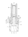
- FIG. 1A is a perspective view of a container-side connector provided with a female connector to which a cap of the present invention is attached.
- FIG. 1B is a cross-sectional perspective view of the container-side connector along the first cross section.
- FIG. 1C is a cross-sectional perspective view of the container-side connector along the second cross-section.
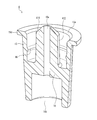
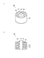
- FIG. 2A is a perspective view of a cap according to Embodiment 1 of the present invention.
- FIG. 2B is a cross-sectional perspective view of the cap according to Embodiment 1 of the present invention.
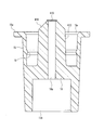
- FIG. 3A is a perspective view illustrating a state in which the cap according to the first embodiment of the present invention is attached to the female connector.
- FIG. 3B is a cross-sectional view showing a state in which the cap according to Embodiment 1 of the present invention is attached to the female connector.
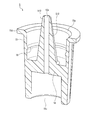
- FIG. 4 is a cross-sectional perspective view of a cap according to Embodiment 2 of the present invention.
- FIG. 5 is a cross-sectional view showing a state in which the cap according to Embodiment 2 of the present invention is attached to the female connector.
- FIG. 6A is a cross-sectional perspective view of a cap according to Embodiment 3 of the present invention.
- FIG. 6B is a plan view of the cap according to the third embodiment of the present invention.
- FIG. 7 is a cross-sectional view showing a state where the cap according to the third embodiment of the present invention is attached to the female connector.
- FIG. 8 is a cross-sectional perspective view of a cap according to Embodiment 4 of the present invention.
- FIG. 9 is sectional drawing which showed the state which mounted
- FIG. 10 is a cross-sectional view of another cap according to Embodiment 4 of the present invention.
- FIG. 11 is a cross-sectional perspective view of the cap concerning Embodiment 5 of this invention.
- FIG. 12 is a cross-sectional view showing a state where the cap according to the fifth embodiment of the present invention is attached to the female connector.
- FIG. 13A is a perspective view of a female connector considered as ISO 80369-3.
- FIG. 13B is a cross-sectional view taken along a plane including the central axis of the female connector.
- FIG. 14A is a perspective view of a male connector being considered as ISO80369-3.
- FIG. 14B is a cross-sectional view taken along a plane including the central axis of the male connector.
- FIG. 15 is a diagram showing an example of the configuration of the enteral nutrition method.
- At least a part of the flow path may be formed between the insertion portion and the tubular portion.
- At least a part of the flow path may be formed in a through hole that penetrates the cap.
- the through hole may be provided, for example, in the insertion portion, or may be provided in a location other than the insertion portion of the cap (for example, a bottom plate, an outer cylinder, etc.).
- the flow path is not formed between the insertion portion and the tubular portion.
- the flow path is not formed on the outer peripheral surface of the tubular portion. Thereby, it can prevent that a liquid substance adheres to the outer peripheral surface of a tubular part after priming. For this reason, the operation which wipes off and removes the liquid substance adhering to the outer peripheral surface of the tubular portion becomes unnecessary. Moreover, possibility that a liquid material will transfer from the outer peripheral surface of a tubular part to the inner peripheral surface of the outer cylinder surrounding a male member can be reduced.
- two or more different flow paths communicating from the base end portion to the outside along the cap may be formed. Thereby, since the cross-sectional area of a flow path expands, priming can be performed in a short time.
- a liquid-tight seal may be formed between the insertion portion and the female connector.
- it can prevent that a liquid substance adheres to the outer peripheral surface of a tubular part after priming. For this reason, the operation which wipes off and removes the liquid substance adhering to the outer peripheral surface of the tubular portion becomes unnecessary.
- possibility that a liquid material will transfer from the outer peripheral surface of a tubular part to the inner peripheral surface of the outer cylinder surrounding a male member can be reduced.
- the cap can be securely attached to the female connector.
- a filter having the property of allowing gas to pass but not liquid to pass may be provided on the flow path. Thereby, it is possible to reduce the possibility of an erroneous operation of leaking the liquid material to the outside during priming.
- the cap of the present invention may further include an engaging portion that engages with the screw-like protrusion.
- a cap can be stably hold
- the operator can recognize that the cap is properly attached to the female connector from the click feeling when the engaging portion engages with the screw projection.
- the flow path communicating from the base end portion to the outside along the cap is formed.
- the cap of the present invention may further include an outer cylinder that covers an outer peripheral surface of the tubular portion when the cap is attached to the female connector.
- the outer cylinder preferably also covers a screw-like protrusion provided on the outer peripheral surface of the tubular portion.
- the tube may be a tube used for enteral nutrition.
- the base end portion is connected to a downstream end of the tube.
- the cap may be attached to the female connector when performing priming for introducing a liquid material into the tube.
- a liquid material flows from the base end portion into the flow path.
- FIG. 1A is a perspective view of the container-side connector 901.
- FIG. 1B is a cross-sectional perspective view of the container-side connector 901 along the first cross section.
- FIG. 1C is a cross-sectional perspective view of the container-side connector 901 along a second cross section orthogonal to the first cross section.
- elements corresponding to those shown in FIGS. 13A and 13B are denoted by the same reference numerals, and description thereof will be omitted.
- the container side connector 901 includes a female connector 910 shown in FIGS. 13A and 13B at one end, and a proximal end portion 917 at the other end.
- the proximal end portion 917 has a hollow cylindrical shape and communicates with a tubular portion 911 that constitutes the female connector 910.
- the inner diameter of the tubular portion 911 is larger than the inner diameter of the proximal end portion 917. Accordingly, a step 916 caused by the difference in inner diameter between the tubular portion 911 and the base end portion 917 is formed.
- the step 916 is defined at the proximal end 917 side end of the portion where the inner diameter between the tubular portion 911 and the proximal end 917 transitions. Accordingly, the inner diameter of the step 916 is smaller than the inner diameter of the tubular portion 911.
- a hollow grip portion 918 surrounds the proximal end portion 917.
- the grip portion 918 includes a pair of grip projections 918 a that protrude toward the opposite sides with respect to the base end portion 917.
- the outer peripheral surface of the grip part 918 has a flat box shape.
- the container-side connector 901 is attached to the downstream end of the tube 935. Specifically, the base end portion 917 of the container side connector 901 is inserted into the opening at the downstream end of the tube 935.
- the female connector 910 is connected to the male connector 920 at the upstream end of the catheter 945. The liquid material flows in the container side connector 901 from the base end portion 917 toward the female connector 910.
- priming is performed to fill the tube 935 with liquid before administering the liquid to the patient.
- the cap of the present invention is attached to the female connector 910 of the container-side connector 901 when priming is performed. Below, the cap of this invention is demonstrated.
- FIG. 2A is a perspective view of the cap 1 according to the first embodiment of the present invention.
- FIG. 2B is a cross-sectional perspective view of the cap 1.
- “vertical direction” and “horizontal direction” are defined based on the orientation (posture) of the cap 1 shown in FIGS. 2A and 2B. The same applies to Embodiments 2 to 5 described later. However, the “vertical direction” and “horizontal direction” do not mean the direction in actual use of the cap of the present invention.
- the cap 1 includes a hollow cylindrical outer cylinder 15.
- the cross-sectional shape of the inner peripheral surface of the outer cylinder 15 on the surface along the horizontal direction is substantially a circle.
- a bottom plate 18 is provided in the outer cylinder 15 at a position retracted from the upper opening 15 a of the outer cylinder 15.
- the bottom plate 18 is a so-called blind plate that is not provided with a through hole, and blocks communication between the upper opening 15 a and the lower opening 15 b of the outer cylinder 15.
- the insertion portion 10 protrudes upward from the center of the bottom plate 18.
- the insertion part 10 has a solid substantially cylindrical shape.
- the outer peripheral surface of the insertion portion 10 and the inner peripheral surface of the outer cylinder 15 are separated from each other.
- a rib 16 protruding toward the outer cylinder 15 is provided on the inner peripheral surface of the outer cylinder 15 at a position away from the bottom plate 18.
- the ribs 16 are annular protrusions that are continuous in the circumferential direction (the direction of rotation around the insertion portion 10).
- a flange 15d continuous in the circumferential direction protrudes outward from the upper end of the outer cylinder 15 along the radial direction.
- the material of the cap 1 is not limited, but is preferably a hard material having mechanical strength (rigidity) that is not substantially deformed by an external force.
- resin materials such as polypropylene (PP), polycarbonate (PC), polyacetal (POM), polystyrene, polyamide, polyethylene, hard polyvinyl chloride, ABS (acryl-butadiene-styrene copolymer) can be used.
- Polypropylene, polycarbonate, polyethylene and ABS are preferred.
- the cap 1 can be integrally manufactured as a single part by the injection molding method or the like using the above resin material. It is preferable that the cap 1 has transparency because the presence of a liquid substance can be confirmed through the cap 1.
- the cap 1 can be attached to and detached from the female connector 910 of the container side connector 901.
- FIG. 3A is a perspective view showing a state where the cap 1 is attached to the female connector 910 (see FIGS. 1A to 1C) of the container-side connector 901
- FIG. 3B is a cross-sectional view thereof.
- the tube 935 is connected to the base end portion 917 of the container-side connector 901.
- the tube 935 is not shown in order to simplify the drawing.
- the insertion portion 10 is inserted into the tubular portion 911.
- the outer diameter of the insertion portion 10 is smaller than the inner diameter of the tubular portion 911. For this reason, a gap 11 a is formed between the insertion portion 10 and the tubular portion 911.
- a tubular portion 911 is inserted between the insertion portion 10 and the outer cylinder 15.
- the screw-shaped protrusion 915 protruding from the outer peripheral surface 913 of the tubular portion 911 is located closer to the bottom plate 18 than the rib 16 protruding from the inner peripheral surface of the outer cylinder 15.
- the inner diameter of the rib 16 is slightly smaller than the outer diameter (thread diameter) of the screw-like protrusion 915. For this reason, the rib 16 is engaged with the screw-shaped protrusion 915. Therefore, the cap 1 does not fall off from the female connector 910.
- the bottom plate 18 and the tip of the tubular portion 911 are separated from each other. Accordingly, a gap 11b is formed between the bottom plate 18 and the tip of the tubular portion 911.
- the inner diameter of the inner peripheral surface of the outer cylinder 15 and the inner diameter of the rib 16 are both larger than the outer diameter of the outer peripheral surface 913 of the tubular portion 911. Accordingly, a gap 11 c is formed between the inner peripheral surface of the outer cylinder 15 and the outer peripheral surface 913 of the tubular portion 911.
- the screw-like projection 915 is a discontinuous screw in which the thread is divided (see FIG. 1A). Therefore, in FIG. 3B, in the gap 11c between the outer cylinder 15 and the tubular portion 911, the lower portion and the upper portion with respect to the screw projection 915 are divided portions of the screw projection 915 ( It communicates via a non-continuous part).
- the screw-like projection 915 may be a continuous screw in which a non-continuous portion is not provided on the thread, and in that case, a lower portion of the gap 11c with respect to the screw-like projection 915. And the upper portion communicate with each other through the groove of the continuous screw.
- the base end portion 917 of the container-side connector 901 communicates with the upper opening 15a of the outer cylinder 15 through the gap 11a, the gap 11b, and the gap 11c in this order.
- priming is performed as follows.
- the clamp 938 is closed with the container side connector 901 and the patient side connector 902 separated.
- the cap 1 is attached to the female connector 910 of the container-side connector 901 (see FIGS. 3A and 3B).
- a liquid material is injected into the container 931.
- the clamp 938 is opened. The liquid material passes through the tube 935 and flows into the base end portion 917 of the container-side connector 901.
- the gap 11a, the gap 11b, and the gap 11c are formed between the female connector 910 and the cap 1, and these communicate with each other.
- the liquid material reaches the opening 15a on the upper side of the outer cylinder 15 from the base end portion 917 through the gap 11a, the gap 11b, and the gap 11c in this order.
- the clamp 938 is closed.
- the cap 1 is removed from the female connector 910.
- the male connector 920 (see FIG. 15) of the patient-side connector 902 is connected to the female connector 910.
- the clamp 938 is opened, and the liquid is administered to the patient via the catheter 945.
- the insertion portion 10 when the cap 1 is attached to the female connector 910, the insertion portion 10 is inserted into the tubular portion 911.
- the gaps 11a, 11b, and 11c formed between the cap 1 and the female connector 910 constitute a flow path that connects the base end portion 917 and the outside (opening 15a). For this reason, a liquid substance can be introduced into this flow path (gap 11a, 11b, 11c) at the time of priming.
- the insertion portion 10 comes out of the tubular portion 911.
- the amount of the liquid material remaining in the tubular portion 911 is the same as or less than the volume of the flow path 11a.
- the amount of the liquid material remaining in the tubular portion 911 at the end of the priming is small. Therefore, after that, when the male member 921 (see FIGS. 14A and 14B) of the male connector 920 is inserted into the tubular portion 911, the gap 926 (see FIG. 14B) between the male member 921 and the outer cylinder 923 is inserted. The amount of liquid that flows out can be reduced. As a result, after the enteral nutrition method is completed and the female connector 910 is separated from the male connector 920, the liquid material remaining in the gap 926 between the male member 921 and the outer cylinder 923 can be reduced.
- the liquid material flows into the gap 11c during priming. Therefore, after removing the cap 1 from the female connector 910, it is preferable to wipe off and remove the liquid material attached to the outer peripheral surface 913 of the tubular portion 911 of the female connector 910. Thereby, after that, when the male connector 920 is connected to the female connector 910, the possibility that the liquid material is transferred to the inner peripheral surface of the outer cylinder 923 can be reduced. This is advantageous in maintaining good hygiene of the male connector 920 after the enteral nutrition method is completed. Since the outer peripheral surface 913 is exposed to the outside, it is easy to wipe off and remove the liquid material adhering to the outer peripheral surface 913 of the tubular portion 911.
- the rib 16 protruding from the inner peripheral surface of the outer cylinder 15 functions as an engaging portion that engages with the screw-shaped protrusion 915 of the female connector 910.
- the force that pushes the cap 1 toward the female connector 910 to attach the cap 1 to the female connector 910 slightly increases when the rib 16 gets over the screwing protrusion 915, and the rib 16 gets over the screwing protrusion 915. Immediately after that, it decreases rapidly. The operator can feel the change in force as a click feeling, and thereby recognize that the cap 1 is properly attached to the female connector 910.
- the ribs 16 engage with the screw-like projections 915, so that the pressure of the liquid material flowing into the gaps 11a, 11b, 11c due to gravity or vibration or during priming This prevents the cap 1 from falling off the female connector 910.
- the cap 1 can be left attached to the female connector 910 when priming and enteral nutrition are not performed.
- the outer cylinder 15 covers almost the entire outer peripheral surface 913 (including the screw-shaped protrusion 915) of the tubular portion 911, so that the outer peripheral surface 913 of the tubular portion 911 is prevented from becoming dirty. Can do.
- the bottom plate 18 prevents the inner peripheral surface 912 of the tubular portion 911 from becoming dirty.
- a flow path (see FIG. 3B) along the cap 1 that allows the base end portion 917 to communicate with the outside world when the cap 1 is attached to the female connector 910 may be formed by a method other than the above embodiment.
- the outer peripheral surface of the insertion portion 10 may be a male tapered surface whose diameter and taper angle coincide with those of the inner peripheral surface 912 of the tubular portion 911.
- the outer peripheral surface of the insertion portion 10 may be in close contact with the inner peripheral surface 912 of the tubular portion 911.
- a groove extending from the distal end of the insertion portion 10 to the bottom plate 18 along the longitudinal direction of the insertion portion 10 may be formed on the outer peripheral surface of the insertion portion 10. This groove can be used as a gap 11 a between the insertion portion 10 and the tubular portion 911.
- the distal end of the tubular portion 911 may abut on the bottom plate 18.
- a groove extending from the insertion portion 10 to the outer cylinder 15 may be formed in the bottom plate 18. This groove can be used as a gap 11b between the bottom plate 18 and the tip of the tubular portion 911.
- the length and outer diameter of the insertion portion 10 can be freely set as long as a liquid material can flow between the insertion portion 10 and the tubular portion 911 during priming. As the length of the insertion portion 10 is longer and the outer diameter of the insertion portion 10 is larger, the amount of liquid material remaining in the tubular portion 911 after the cap 1 is removed from the female connector 910 can be reduced. This is advantageous in reducing the amount of liquid remaining in the gap 926 (see FIG. 14B) between the male member 921 and the outer cylinder 923 upon completion of enteral nutrition. On the other hand, if the insertion portion 10 is long and its outer diameter is large, the cross-sectional area of the flow path through which the liquid material flows during priming becomes small, so that a long time is required for priming.
- the volume of the portion of the insertion portion 10 present in the tubular portion 911 is more than half of the volume of the lumen of the tubular portion 911, and more than two-thirds, In particular, it is preferably 3/4 or more.
- the length of the insertion portion 10 when the cap 1 is attached to the female connector 910, the distal end of the insertion portion 10 reaches the vicinity of the step 916 at the boundary portion between the tubular portion 911 and the base end portion 917. Preferably reached.
- the outer cylinder 15 of the cap 1 extends below the bottom plate 18 (on the side opposite to the insertion portion 10). However, even if the portion below the bottom plate 18 of the outer cylinder 15 is omitted. Good.
- the rib 16 as the engaging portion protruding from the inner peripheral surface of the outer cylinder 15 can have any shape other than the above-described embodiment as long as it can engage with the screw-shaped protrusion 915 of the female connector 910.
- the engaging portion may be a discontinuous protrusion divided in the circumferential direction.
- the engaging portion may constitute a screw thread (female screw) that is screwed with the screw-shaped protrusion 915.
- the fact that the engaging portion is an annular rib 16 that is continuous in the circumferential direction as in the present embodiment means that the rotational direction of the cap 1 is even when the screw-like projection 915 is a discontinuous screw as shown in FIG. 1A. This is advantageous because the engaging portion can be reliably engaged with the screw-shaped protrusion 915 regardless of the position of the screw.
- the plurality of protrusions 15 c formed on the outer peripheral surface of the outer cylinder 15 are effective for the operator to firmly hold the cap 1 when the cap 1 is attached to the female connector 910.
- any shape other than the protrusions 15c may be provided on the outer peripheral surface of the outer cylinder 15.
- the protrusion 15c may be omitted.
- the outer peripheral surface of the outer cylinder 15 does not need to be a substantially cylindrical surface, and may be a regular polygonal column surface such as a regular octagonal column surface or a regular hexagonal column surface.
- the flange 15d can be used for an operator to apply force to the cap 1 when the cap 1 is attached to and detached from the female connector 910.
- the flange 15d is provided at the upper end of the outer cylinder 15.
- the position of the flange 15d is not limited to this, and may be provided at an arbitrary position between the upper end and the lower end of the outer cylinder 15. it can.
- the flange 15 can be provided at the lower end of the outer cylinder 15, and this configuration is advantageous for applying a force away from the female connector 910 to the cap 1 when the cap 1 is separated from the female connector 910. It is possible.
- Two or more flanges 15d may be provided at different positions in the vertical direction.
- the flange 15d may be an annular protrusion that is continuous in the circumferential direction as in the above-described embodiment, but is not limited thereto, and may be composed of, for example, one or more protrusions that are not continuous in the circumferential direction. . In the present invention, the flange 15d may be omitted.
- FIG. 4 is a cross-sectional perspective view of the cap 2 according to the second embodiment of the present invention.
- the cap 2 of the second embodiment is different from the cap 1 of the first embodiment in that a through hole 10 a is formed in the insertion portion 10 and the bottom plate 18.
- the second embodiment will be described with a focus on differences from the first embodiment.
- the same reference numerals are given to the same elements as those in the drawings referred to in the first embodiment, and description thereof will be omitted.
- the through-hole 10a penetrates the insertion part 10 and the bottom plate 18 in the vertical direction. Accordingly, the upper opening 15a and the lower opening 15b of the outer cylinder 15 communicate with each other through the through hole 10a.
- the cap 2 can be attached to and detached from the female connector 910 of the container side connector 901.
- FIG. 5 is a cross-sectional view showing a state where the cap 2 is attached to the female connector 910 (see FIGS. 1A to 1C) of the container-side connector 901.
- a tube 935 is connected to the base end portion 917 of the container-side connector 901.
- the tube 935 is not shown in order to simplify the drawing.
- the insertion portion 10 is inserted into the tubular portion 911. Further, a gap 11a, a gap 11b, and a gap 11c are formed between the cap 2 and the female connector 910. Therefore, the base end portion 917 of the container side connector 901 communicates with the opening 15a on the upper side of the outer cylinder 15 through the gap 11a, the gap 11b, and the gap 11c in this order.
- the base end portion 917 of the container side connector 901 communicates with the lower opening 15 b of the outer cylinder 15 through the insertion portion 10 and the through hole 10 a provided in the bottom plate 18.
- the priming method using the cap 2 is substantially the same as in the first embodiment.
- the through hole 10 a is formed in the insertion portion 10 and the bottom plate 18. Therefore, when the clamp 938 is opened with the cap 2 attached to the female connector 910, the liquid material passes through the gap 11a, the gap 11b, and the gap 11c in this order from the base end portion 917 to the opening 15a on the upper side of the outer cylinder 15. In addition to reaching, the base end portion 917 also reaches the lower opening 15b of the outer cylinder 15 through the through hole 10a. After confirming that the liquid has reached the opening 15a and / or the opening 15b, the clamp 938 is closed. Thereafter, the cap 2 is removed from the female connector 910 as in the first embodiment.
- the amount of the liquid material remaining in the tubular portion 911 is the same as or less than the volume of the flow path 11a. Therefore, after that, when the male member 921 (see FIGS. 14A and 14B) is inserted into the tubular portion 911, the liquid material that flows out to the gap 926 (see FIG. 14B) between the male member 921 and the outer cylinder 923 is used. The amount can be reduced. As a result, after the enteral nutrition method is completed and the female connector 910 is separated from the male connector 920, the liquid material remaining in the gap 926 between the male member 921 and the outer cylinder 923 can be reduced.
- the second embodiment is the same as the first embodiment except for the above.
- the description of the first embodiment is also applied to the second embodiment.
- FIG. 6A is a cross-sectional perspective view of the cap 3 according to the third embodiment of the present invention.
- FIG. 6B is a plan view of the cap 3.
- the cap 3 according to the third embodiment is different from the cap 1 according to the first embodiment in that a through hole 18 a is formed in the bottom plate 18.
- the third embodiment will be described with a focus on differences from the first embodiment.
- the same elements as those in the drawings referred to in the first embodiment are denoted by the same reference numerals, and description thereof is omitted.
- Two through holes 18a are formed at substantially symmetrical positions with respect to the insertion portion 10 of the bottom plate 18. Accordingly, the upper opening 15a and the lower opening 15b of the outer cylinder 15 communicate with each other through the through hole 18a.
- the cap 3 can be attached to and detached from the female connector 910 of the container side connector 901.
- FIG. 7 is a cross-sectional view showing a state in which the cap 3 is attached to the female connector 910 (see FIGS. 1A to 1C) of the container-side connector 901.
- FIG. 7 Actually, the tube 935 is connected to the base end portion 917 of the container-side connector 901. However, in FIG. 7, the tube 935 is not shown in order to simplify the drawing.
- the insertion portion 10 is inserted into the tubular portion 911.
- a gap 11a, a gap 11b, and a gap 11c are formed between the cap 3 and the female connector 910. Therefore, the base end portion 917 of the container side connector 901 communicates with the opening 15a on the upper side of the outer cylinder 15 through the gap 11a, the gap 11b, and the gap 11c in this order.
- the base end portion 917 of the container side connector 901 communicates with the lower opening 15b of the outer cylinder 15 through the gap 11a and the through hole 18a provided in the bottom plate 18. .
- the priming method using the cap 3 is substantially the same as in the first embodiment.
- a through hole 18 a is formed in the bottom plate 18. Therefore, when the clamp 938 is opened with the cap 3 attached to the female connector 910, the liquid material passes through the gap 11a, the gap 11b, and the gap 11c in this order from the base end portion 917 to the upper opening 15a of the outer cylinder 15. In addition to reaching, the base end 917 also reaches the lower opening 15b of the outer cylinder 15 through the gap 11a and the through hole 18a in this order. After confirming that the liquid has reached the opening 15a and / or the opening 15b, the clamp 938 is closed. Thereafter, the cap 3 is removed from the female connector 910 as in the first embodiment.
- the cap 3 when the cap 3 is attached to the female connector 910, in addition to the first flow path communicating from the base end portion 917 to the outside (opening 15a) through the gaps 11a, 11b, and 11c, A second flow path is formed which communicates from the base end portion 917 to the outside (opening 15b) through the gap 11a and the through hole 18a. For this reason, a liquid substance can be introduced into these two flow paths (gap 11a, 11b, 11c; gap 11a, through hole 18a) during priming. Thereafter, the cap 3 is removed from the female connector 910. Similar to the first embodiment, the amount of the liquid material remaining in the tubular portion 911 is the same as or less than the volume of the flow path 11a.
- the liquid material that flows out to the gap 926 (see FIG. 14B) between the male member 921 and the outer cylinder 923 is used.
- the amount can be reduced.
- the enteral nutrition method is completed and the female connector 910 is separated from the male connector 920, the liquid material remaining in the gap 926 between the male member 921 and the outer cylinder 923 can be reduced.
- the two through holes 18a are formed in the bottom plate 18.
- the number of the through holes 18a is not limited to two, but may be one or three or more. Also good.
- the through hole 18a is formed in the bottom plate 18.
- the outer cylinder 15 is provided with a through hole that penetrates the outer cylinder 15 in the radial direction. Also good.
- the through-hole is provided, for example, in a region of the outer cylinder 15 between the bottom plate 18 and the rib 16, in particular, a region between the bottom plate 18 and the screw-shaped protrusion 915 so as to communicate with the gap 11 b or the gap 11 c. it can.
- the number of through holes may be one or two or more.
- the cap 1 according to the first embodiment and the cap 2 according to the second embodiment may be provided with a through hole in the outer cylinder 15.
- the third embodiment is the same as the first embodiment except for the above.
- the description of the first embodiment is also applied to the third embodiment.
- the through hole 18a of the bottom plate 18 described in the third embodiment may be applied to the cap 2 of the second embodiment.
- the cap when the cap is attached to the female connector 910, three flow paths that connect the base end portion 917 and the outside world are formed. Therefore, since the cross-sectional area of the flow path is enlarged, priming can be performed in a shorter time.
- FIG. 8 is a cross-sectional perspective view of the cap 4 according to the fourth embodiment of the present invention.
- the cap 4 of the fourth embodiment is different from the cap 1 of the first embodiment in the following two points.
- a male taper surface whose outer diameter and taper angle coincide with the female taper surface (see FIGS. 13A and 13B) formed on the inner peripheral surface 912 of the tubular portion 911 of the female connector 910 on the outer peripheral surface 412 of the insertion portion 410. Is formed.
- a through hole 10 a similar to that of the second embodiment is formed in the insertion portion 410 and the bottom plate 18.
- the fourth embodiment will be described with a focus on differences from the first embodiment.
- the same reference numerals are given to the same elements as those in the drawings referred to in the first embodiment, and description thereof is omitted.
- the outer peripheral surface 412 of the insertion part 410 is the same male tapered surface as the outer peripheral surface 922 (see FIGS. 14A and 14B) of the male member 921 of the male connector 920 that matches the female connector 910. Therefore, when the insertion portion 410 is inserted into the tubular portion 911 of the female connector 910, the outer peripheral surface 412 of the insertion portion 410 and the inner peripheral surface 912 of the tubular portion 911 are fitted in a liquid-tight manner, and a liquid-tight state is formed therebetween. A seal is formed.
- the through-hole 10a penetrates the insertion portion 410 and the bottom plate 18 in the vertical direction. Accordingly, the upper opening 15a and the lower opening 15b of the outer cylinder 15 communicate with each other through the through hole 10a.
- the cap 4 can be attached to and detached from the female connector 910 of the container side connector 901.
- FIG. 9 is a cross-sectional view showing a state in which the cap 4 is attached to the female connector 910 (see FIGS. 1A to 1C) of the container side connector 901.
- a tube 935 is connected to the base end portion 917 of the container-side connector 901.
- the tube 935 is not shown in order to simplify the drawing.
- the insertion portion 410 is inserted into the tubular portion 911.
- the outer peripheral surface 412 of the insertion portion 410 and the inner peripheral surface 912 of the tubular portion 911 are in close contact, and a liquid-tight seal is formed between them.
- the distal end of the insertion portion 410 reaches a step 916 at the boundary between the tubular portion 911 and the proximal end portion 917. Therefore, the gap 11a formed in the first to third embodiments does not substantially exist between the insertion portion 10 and the tubular portion 911.
- a gap 11b and a gap 11c are formed between the cap 4 and the female connector 910.
- the base end portion 917 of the container side connector 901 does not communicate with the upper opening 15 a of the outer cylinder 15.
- the base end portion 917 of the container-side connector 901 communicates with the lower opening 15b of the outer cylinder 15 through the insertion portion 410 and the through hole 10a provided in the bottom plate 18.
- the priming method using the cap 4 is substantially the same as in the first embodiment.
- the flow path from the base end portion 917 to the upper opening 15a is blocked. Instead, there is a flow path from the base end portion 917 to the lower opening 15b through the through hole 10a. Accordingly, when the clamp 938 is opened with the cap 4 attached to the female connector 910, the liquid material reaches the lower opening 15b of the outer cylinder 15 from the base end portion 917 through the through hole 10a. After confirming that the liquid has reached the opening 15b, the clamp 938 is closed. Thereafter, the cap 4 is removed from the female connector 910 as in the first embodiment.
- the cap 4 when the cap 4 is attached to the female connector 910, a flow path that communicates from the base end portion 917 to the outside (opening 15b) through the through hole 10a is formed. For this reason, a liquid substance can be introduced into the flow path (through hole 10a) during priming. Thereafter, the cap 4 is removed from the female connector 910.
- the gap 11a is not substantially formed in the tubular portion 911.
- the liquid material in the through hole 10 a is removed from the tubular portion 911 together with the cap 4. Therefore, almost no liquid material remains in the tubular portion 911 after the cap 4 is removed. Therefore, after that, when the male member 921 (see FIGS.
- the liquid material does not flow into the gap 11b and the gap 11c during priming. That is, the flow path through which the liquid material flows is not formed on the outer peripheral surface 913 of the tubular portion 911.
- the liquid material does not adhere to the outer peripheral surface 913 of the tubular portion 911 after priming.
- the operation preferably performed in the first to third embodiments of wiping and removing the liquid material adhering to the outer peripheral surface 913 of the tubular portion 911 is unnecessary in the fourth embodiment. is there.
- the liquid material may be transferred from the outer peripheral surface 913 of the tubular portion 911 to the inner peripheral surface of the outer cylinder 923. Very low. This is advantageous in maintaining good hygiene of the male connector 920 after the enteral nutrition method is completed.
- the distal end of the insertion portion 410 when the cap 4 is attached to the female connector 910, the distal end of the insertion portion 410 reaches the step 916. However, the distal end of the insertion portion 410 may not reach the step 916. Even if the insertion portion 410 is shorter than the depth of the tubular portion 911, it is possible to form a liquid-tight seal between the outer peripheral surface 412 of the insertion portion 410 and the inner peripheral surface 912 of the tubular portion 911. However, the shorter the insertion portion 410, the more liquid is left in the tubular portion 911 after the cap 4 is removed from the female connector 910.
- the insertion depth of the insertion portion 410 with respect to the tubular portion 911 is the depth of the tubular portion 911 (the distance from the distal end of the tubular portion 911 to the step 916).
- the depth of the tubular portion 911 is the distance from the distal end of the tubular portion 911 to the step 916.
- the insertion portion 410 and the container-side connector 901 are fitted in a liquid-tight manner. Therefore, the bond strength between the two is relatively high. If the cap 4 does not fall off the female connector 910 during priming, the rib 16 that engages with the screw-shaped protrusion 915 can be omitted. Furthermore, the outer cylinder 15 and the bottom plate 18 can be omitted. In this case, the insertion portion 410 can be extended downward to provide a holding portion for the operator to hold the cap 4.
- a ventilation filter 419 may be provided so as to close the through hole 10a.
- the ventilation filter 419 is a filter having a property of allowing gas to pass but not allowing liquid to pass through, and may be referred to as a “hydrophobic filter”.
- the ventilation filter 419 is preferably provided at the distal end of the insertion portion 410 as shown in FIG. Thereby, since it can prevent that a liquid substance flows in into the through-hole 10a, the quantity of the liquid substance discarded wastefully can be decreased.
- the position where the ventilation filter 419 is provided is not limited to this, and may be, for example, an opening on the lower side (bottom plate 18 side) of the through hole 10a or an arbitrary position in the through hole 10a. Good.
- the fourth embodiment is the same as the first embodiment except for the above.
- the description of the first embodiment is also applied to the fourth embodiment.
- FIG. 11 is a cross-sectional perspective view of the cap 5 according to the fifth embodiment of the present invention.
- the cap 5 of the fifth embodiment is different from the cap 4 of the fourth embodiment with respect to the shape of the outer peripheral surface 512 of the insertion portion 510.
- the fifth embodiment will be described with a focus on differences from the fourth embodiment.
- the same reference numerals are given to the same elements as those in the drawings referred to in the fourth embodiment, and description thereof will be omitted.
- the outer peripheral surface 512 of the insertion portion 510 is a tapered surface (male tapered surface) whose outer diameter decreases as it approaches the tip.
- the male tapered surface of the outer peripheral surface 512 has a larger taper angle than the male tapered surface provided on the outer peripheral surface 412 of the insertion portion 410 of the fourth embodiment.
- the insertion portion 510 extends higher upward than the insertion portion 410 of the fourth embodiment.
- the insertion part 510 and the bottom plate 18 are formed with the same through-hole 10a as in the second and fourth embodiments.
- the through hole 10a penetrates the insertion portion 510 and the bottom plate 18 in the vertical direction. Accordingly, the upper opening 15a and the lower opening 15b of the outer cylinder 15 communicate with each other through the through hole 10a.
- the cap 5 can be attached to and detached from the female connector 910 of the container side connector 901.
- FIG. 12 is a cross-sectional view showing a state where the cap 5 is attached to the female connector 910 (see FIGS. 1A to 1C) of the container-side connector 901.
- FIG. 12 Actually, the tube 935 is connected to the base end portion 917 of the container-side connector 901. However, in FIG. 12, the tube 935 is not shown in order to simplify the drawing.
- the insertion portion 510 is inserted into the tubular portion 911.
- a gap 11a, a gap 11b, and a gap 11c are formed between the cap 5 and the female connector 910.
- the outer peripheral surface 512 of the insertion portion 510 is fitted to the step 916 at the boundary portion between the tubular portion 911 and the base end portion 917, and the liquid-tightness is between the insertion portion 510 and the step 916.
- a seal is formed. Therefore, the base end portion 917 of the container side connector 901 does not communicate with the gap 11a. Accordingly, the base end portion 917 does not communicate with the upper opening 15 a of the outer cylinder 15.
- the base end portion 917 of the container-side connector 901 is inserted into the lower opening 15b of the outer cylinder 15 via the insertion portion 510 and the through hole 10a provided in the bottom plate 18. Communicate.
- the priming method using the cap 5 is substantially the same as in the fourth embodiment. Similarly to the fourth embodiment, the flow path from the base end portion 917 to the upper opening 15a is also blocked in the fifth embodiment. Instead, there is a flow path from the base end portion 917 to the lower opening 15b through the through hole 10a. Accordingly, when the clamp 938 is opened with the cap 5 attached to the female connector 910, the liquid material passes from the base end portion 917 through the through hole 10a to the lower opening 15b of the outer cylinder 15 from the base end portion 917. To reach. After confirming that the liquid has reached the opening 15b, the clamp 938 is closed. Thereafter, the cap 5 is removed from the female connector 910.
- the insertion portion 510 and the step 916 are fitted in a liquid-tight manner. Therefore, the liquid material does not flow into the gap 11a between the insertion portion 10 and the tubular portion 911 during priming.
- the liquid material in the through hole 10 a is removed from the tubular portion 911 together with the cap 5. Therefore, as in the fourth embodiment, the liquid material hardly remains in the tubular portion 911 after the cap 5 is removed. Therefore, after that, when the male member 921 (see FIGS. 14A and 14B) is inserted into the tubular portion 911, almost no liquid material is present in the gap 926 (see FIG. 14B) between the male member 921 and the outer cylinder 923. It will not flow out.
- the liquid material remaining in the gap 926 between the male member 921 and the outer cylinder 923 is further increased than in the first to third embodiments. Can be reduced.
- the liquid material does not flow into the gap 11b and the gap 11c during priming. That is, the flow path through which the liquid material flows is not formed on the outer peripheral surface 913 of the tubular portion 911.
- the liquid material does not adhere to the outer peripheral surface 913 of the tubular portion 911 after priming. For this reason, after removing the cap 5 from the female connector 910, the operation of wiping and removing the liquid material adhering to the outer peripheral surface 913 of the tubular portion 911 is unnecessary.
- the liquid material may be transferred from the outer peripheral surface 913 of the tubular portion 911 to the inner peripheral surface of the outer cylinder 923. Very low. This is advantageous in maintaining good hygiene of the male connector 920 after the enteral nutrition method is completed.
- a single male tapered surface is formed on the outer peripheral surface 512 of the insertion portion 510 in the entire region from the bottom plate 18 to the tip of the insertion portion 510.
- the shape of the outer peripheral surface 512 of the insertion part 510 is not limited to this. If a liquid-tight seal is formed between the insertion portion 510 and the inner peripheral surface of the container-side connector 901, the shape of the outer peripheral surface 512 can be arbitrarily changed.
- a male taper surface is formed only in a portion that fits in the step 916 and a portion in the vicinity of the outer peripheral surface of the insertion portion 510, and a portion closer to the bottom plate 18 can have an arbitrary shape (eg, a cylindrical surface) .
- the position where the liquid-tight seal is formed is not limited to the step 916. It may be in the tubular portion 911 in front of the step 916, or in the proximal end portion 917 in the back of the step 916.
- the formation of a liquid-tight seal at the step 916 or the base end portion 917 is preferable because the amount of liquid remaining in the tubular portion 911 after the cap 5 is removed can be reduced.
- the outer peripheral surface of the insertion portion 510 does not need to be in direct contact with the inner peripheral surface of the container-side connector 901.
- a sealing member may be provided on the outer peripheral surface of the insertion portion 510, and the sealing member may be brought into liquid-tight contact with the inner peripheral surface of the container side connector 901.
- the method of providing the seal member is arbitrary.
- an O-ring may be attached to the outer peripheral surface of the insertion portion 510, and rubber such as silicone rubber or elastomer having rubber elasticity such as thermoplastic elastomer is inserted by two-color molding. You may integrally provide in the outer peripheral surface of the part 510.
- Embodiment 5 is the same as Embodiments 1 and 4 except for the above.
- the description of the first and fourth embodiments is also applied to the fifth embodiment.
- the configuration of the container-side connector provided with the female connector 910 to which the cap of the present invention is attached is not limited to FIGS. 1A to 1C.
- a female connector 910 conforming to ISO 80369-3 may be provided, and a base end portion 917 communicating with the tubular portion 911 of the female connector 910 may be provided.
- the configuration of parts not defined in ISO 80369-3 can be arbitrarily changed.
- the inner diameter of the base end portion 917 does not need to be the same as the inner diameter of the step 916 and may be larger than the inner diameter of the tubular portion 911.
- a step 916 having a smaller diameter than the tubular portion 911 is provided between the tubular portion 911 and the base end portion 917.
- the configuration of the grip portion 918 can also be arbitrarily changed.
- the shape of the grip protrusion 918a may be changed, or the grip protrusion 918a may be omitted.
- the grip portion 918 including the grip protrusion 918a may be omitted.
- the configuration of the tube connected to the base end 917 of the container-side connector is not limited to that shown in FIG. Any tube can be connected to the proximal end 917.
- a known clamp for opening and closing the flow path of the tube 935 may be provided in the tube 935. In this case, the start / stop switching of the introduction of the liquid material into the tube 935 can be performed using the clamp.
- the male connector 920 to which the female connector 910 is connected is provided at the upstream end of the catheter 945 placed in the patient, but the present invention is not limited to this.
- a flexible tube may be connected to the upstream end of the catheter placed in the patient, and a male connector 920 may be provided at the upstream end of the tube.
- the present invention can be preferably used for priming a tube provided with a female connector (see FIGS. 13A and 13B) compliant with ISO 80369-3 at the downstream end. Among them, it can be preferably used for priming in the medical field, particularly enteral nutrition.
Landscapes
- Health & Medical Sciences (AREA)
- Heart & Thoracic Surgery (AREA)
- Pulmonology (AREA)
- Engineering & Computer Science (AREA)
- Anesthesiology (AREA)
- Biomedical Technology (AREA)
- Hematology (AREA)
- Life Sciences & Earth Sciences (AREA)
- Animal Behavior & Ethology (AREA)
- General Health & Medical Sciences (AREA)
- Public Health (AREA)
- Veterinary Medicine (AREA)
- Infusion, Injection, And Reservoir Apparatuses (AREA)
Abstract
Selon la présente invention, un raccord femelle (910) est pourvu d'une section en forme de tube (911) ayant une forme tubulaire. Une saillie en forme de vis (915) est prévue sur la surface circonférentielle extérieure (913) de la section en forme de tube, et une surface conique dont le diamètre intérieur augmente progressivement vers la pointe de cette dernière est présente sur la surface circonférentielle intérieure (912) de la section en forme de tube. La section en forme de tube communique avec une section extrémité de base (917) à laquelle un tube flexible (935) est raccordé. Le capuchon (1) de la présente invention est fixé de manière amovible sur le raccord femelle (910) décrit ci-dessus. Le capuchon est pourvu d'une section insertion (10). Lorsque le capuchon est fixé au raccord femelle, la section insertion est insérée dans la section en forme de tube, et des passages d'écoulement (11a, 11b, 11c) communiquant avec l'environnement extérieur sont formés le long du capuchon depuis l'extrémité de base.
Priority Applications (1)
| Application Number | Priority Date | Filing Date | Title |
|---|---|---|---|
| JP2017510016A JP7077016B2 (ja) | 2015-03-30 | 2016-03-29 | キャップ |
Applications Claiming Priority (2)
| Application Number | Priority Date | Filing Date | Title |
|---|---|---|---|
| JP2015069586 | 2015-03-30 | ||
| JP2015-069586 | 2015-03-30 |
Publications (1)
| Publication Number | Publication Date |
|---|---|
| WO2016158937A1 true WO2016158937A1 (fr) | 2016-10-06 |
Family
ID=57006021
Family Applications (1)
| Application Number | Title | Priority Date | Filing Date |
|---|---|---|---|
| PCT/JP2016/060088 WO2016158937A1 (fr) | 2015-03-30 | 2016-03-29 | Capuchon |
Country Status (2)
| Country | Link |
|---|---|
| JP (1) | JP7077016B2 (fr) |
| WO (1) | WO2016158937A1 (fr) |
Cited By (2)
| Publication number | Priority date | Publication date | Assignee | Title |
|---|---|---|---|---|
| EP3466480A1 (fr) * | 2017-10-06 | 2019-04-10 | Q Medical International AG | Dispositif de connexion pour tubes d'étalonnage gastriques ainsi que système médical doté d'un dispositif de connexion pour tubes d'étalonnage gastriques et d'un tube d'étalonnage gastrique |
| US11674614B2 (en) | 2020-10-09 | 2023-06-13 | Icu Medical, Inc. | Fluid transfer device and method of use for same |
Citations (3)
| Publication number | Priority date | Publication date | Assignee | Title |
|---|---|---|---|---|
| JPH08155025A (ja) * | 1994-12-01 | 1996-06-18 | Jms Co Ltd | 医療用コネクタ− |
| JP2008183232A (ja) * | 2007-01-30 | 2008-08-14 | Nippon Sherwood Medical Industries Ltd | コネクター用キャップ |
| JP2010527276A (ja) * | 2007-05-16 | 2010-08-12 | アイシーユー・メディカル・インコーポレーテッド | 閉鎖可能な雄ルアーを備える医療用コネクタ |
Family Cites Families (2)
| Publication number | Priority date | Publication date | Assignee | Title |
|---|---|---|---|---|
| DE3515665C1 (de) * | 1985-05-02 | 1986-05-15 | Gerhard 6393 Wehrheim Pfetzing | Verschlußstopfen |
| JP6151614B2 (ja) * | 2013-09-12 | 2017-06-21 | 日機装株式会社 | 医療用キャップ付コネクタ |
-
2016
- 2016-03-29 WO PCT/JP2016/060088 patent/WO2016158937A1/fr active Application Filing
- 2016-03-29 JP JP2017510016A patent/JP7077016B2/ja active Active
Patent Citations (3)
| Publication number | Priority date | Publication date | Assignee | Title |
|---|---|---|---|---|
| JPH08155025A (ja) * | 1994-12-01 | 1996-06-18 | Jms Co Ltd | 医療用コネクタ− |
| JP2008183232A (ja) * | 2007-01-30 | 2008-08-14 | Nippon Sherwood Medical Industries Ltd | コネクター用キャップ |
| JP2010527276A (ja) * | 2007-05-16 | 2010-08-12 | アイシーユー・メディカル・インコーポレーテッド | 閉鎖可能な雄ルアーを備える医療用コネクタ |
Cited By (5)
| Publication number | Priority date | Publication date | Assignee | Title |
|---|---|---|---|---|
| EP3466480A1 (fr) * | 2017-10-06 | 2019-04-10 | Q Medical International AG | Dispositif de connexion pour tubes d'étalonnage gastriques ainsi que système médical doté d'un dispositif de connexion pour tubes d'étalonnage gastriques et d'un tube d'étalonnage gastrique |
| CN109621185A (zh) * | 2017-10-06 | 2019-04-16 | Q医疗国际有限公司 | 用于胃校准软管的连接器装置 |
| AU2018241145B2 (en) * | 2017-10-06 | 2020-02-20 | Q Medical International Ag | Connector device for gastric calibration hoses, as well as medical system comprising a connector device for gastric calibration hoses and a gastric calibration hose |
| US11717666B2 (en) | 2017-10-06 | 2023-08-08 | Q Medical International Ag | Connector device for gastric calibration hoses, as well as medical system comprising a connector device for gastric calibration hoses and a gastric calibration hose |
| US11674614B2 (en) | 2020-10-09 | 2023-06-13 | Icu Medical, Inc. | Fluid transfer device and method of use for same |
Also Published As
| Publication number | Publication date |
|---|---|
| JPWO2016158937A1 (ja) | 2018-02-01 |
| JP7077016B2 (ja) | 2022-05-30 |
Similar Documents
| Publication | Publication Date | Title |
|---|---|---|
| KR101800984B1 (ko) | 더블 수 커넥터 | |
| KR102507581B1 (ko) | 의료용 채액 주입기 | |
| CN105979999B (zh) | 阳型连接器 | |
| JP6919794B2 (ja) | メスコネクタ | |
| JP6409273B2 (ja) | オスコネクタ | |
| JP6655185B2 (ja) | 円錐形コネクタ用可撓性キャップ | |
| WO2015146831A1 (fr) | Adaptateur de nettoyage | |
| WO2017141858A1 (fr) | Adaptateur | |
| CN107106789A (zh) | 医疗用采液尖端、采液管嘴以及注入器组件 | |
| KR20170054416A (ko) | 반고형화 영양제용 어댑터 | |
| JP2016158656A (ja) | キャップ付きコネクタ | |
| US8491544B2 (en) | Enteral feeding connector | |
| WO2016158937A1 (fr) | Capuchon | |
| JP6237402B2 (ja) | 洗浄用アダプタ | |
| WO2017104689A1 (fr) | Connecteur femelle | |
| JP2013138707A (ja) | 経腸栄養療法用カテーテルと医療用回路との接続構造、アダプタ付き経腸栄養療法用カテーテル、及びアダプタと医療用回路とを含む医療用送液キット | |
| JP6237403B2 (ja) | 洗浄用アダプタ | |
| JP6677912B2 (ja) | オスコネクタ | |
| JP6427919B2 (ja) | シリンジ | |
| JP6801800B2 (ja) | オスコネクタ | |
| JP6402881B2 (ja) | ダブルメスコネクタ | |
| JP6402880B2 (ja) | ダブルメスコネクタ | |
| JP2022041685A (ja) | キャップ | |
| JP2021037347A (ja) | オスコネクタ |
Legal Events
| Date | Code | Title | Description |
|---|---|---|---|
| 121 | Ep: the epo has been informed by wipo that ep was designated in this application |
Ref document number: 16772818 Country of ref document: EP Kind code of ref document: A1 |
|
| ENP | Entry into the national phase |
Ref document number: 2017510016 Country of ref document: JP Kind code of ref document: A |
|
| NENP | Non-entry into the national phase |
Ref country code: DE |
|
| 122 | Ep: pct application non-entry in european phase |
Ref document number: 16772818 Country of ref document: EP Kind code of ref document: A1 |