WO2016158628A1 - ワイヤーハーネスの製造方法および画像処理方法 - Google Patents
ワイヤーハーネスの製造方法および画像処理方法 Download PDFInfo
- Publication number
- WO2016158628A1 WO2016158628A1 PCT/JP2016/059280 JP2016059280W WO2016158628A1 WO 2016158628 A1 WO2016158628 A1 WO 2016158628A1 JP 2016059280 W JP2016059280 W JP 2016059280W WO 2016158628 A1 WO2016158628 A1 WO 2016158628A1
- Authority
- WO
- WIPO (PCT)
- Prior art keywords
- representative line
- point
- cloud data
- point cloud
- wire assembly
- Prior art date
- Legal status (The legal status is an assumption and is not a legal conclusion. Google has not performed a legal analysis and makes no representation as to the accuracy of the status listed.)
- Ceased
Links
Images



Classifications
-
- H—ELECTRICITY
- H01—ELECTRIC ELEMENTS
- H01B—CABLES; CONDUCTORS; INSULATORS; SELECTION OF MATERIALS FOR THEIR CONDUCTIVE, INSULATING OR DIELECTRIC PROPERTIES
- H01B13/00—Apparatus or processes specially adapted for manufacturing conductors or cables
- H01B13/012—Apparatus or processes specially adapted for manufacturing conductors or cables for manufacturing wire harnesses
- H01B13/01209—Details
-
- G—PHYSICS
- G01—MEASURING; TESTING
- G01B—MEASURING LENGTH, THICKNESS OR SIMILAR LINEAR DIMENSIONS; MEASURING ANGLES; MEASURING AREAS; MEASURING IRREGULARITIES OF SURFACES OR CONTOURS
- G01B11/00—Measuring arrangements characterised by the use of optical techniques
- G01B11/24—Measuring arrangements characterised by the use of optical techniques for measuring contours or curvatures
- G01B11/25—Measuring arrangements characterised by the use of optical techniques for measuring contours or curvatures by projecting a pattern, e.g. one or more lines, moiré fringes on the object
- G01B11/2513—Measuring arrangements characterised by the use of optical techniques for measuring contours or curvatures by projecting a pattern, e.g. one or more lines, moiré fringes on the object with several lines being projected in more than one direction, e.g. grids, patterns
-
- G—PHYSICS
- G01—MEASURING; TESTING
- G01B—MEASURING LENGTH, THICKNESS OR SIMILAR LINEAR DIMENSIONS; MEASURING ANGLES; MEASURING AREAS; MEASURING IRREGULARITIES OF SURFACES OR CONTOURS
- G01B11/00—Measuring arrangements characterised by the use of optical techniques
- G01B11/26—Measuring arrangements characterised by the use of optical techniques for measuring angles or tapers; for testing the alignment of axes
-
- G—PHYSICS
- G06—COMPUTING OR CALCULATING; COUNTING
- G06T—IMAGE DATA PROCESSING OR GENERATION, IN GENERAL
- G06T2207/00—Indexing scheme for image analysis or image enhancement
- G06T2207/10—Image acquisition modality
- G06T2207/10028—Range image; Depth image; 3D point clouds
-
- H—ELECTRICITY
- H01—ELECTRIC ELEMENTS
- H01B—CABLES; CONDUCTORS; INSULATORS; SELECTION OF MATERIALS FOR THEIR CONDUCTIVE, INSULATING OR DIELECTRIC PROPERTIES
- H01B13/00—Apparatus or processes specially adapted for manufacturing conductors or cables
- H01B13/012—Apparatus or processes specially adapted for manufacturing conductors or cables for manufacturing wire harnesses
- H01B13/01236—Apparatus or processes specially adapted for manufacturing conductors or cables for manufacturing wire harnesses the wires being disposed by machine
-
- H—ELECTRICITY
- H01—ELECTRIC ELEMENTS
- H01B—CABLES; CONDUCTORS; INSULATORS; SELECTION OF MATERIALS FOR THEIR CONDUCTIVE, INSULATING OR DIELECTRIC PROPERTIES
- H01B13/00—Apparatus or processes specially adapted for manufacturing conductors or cables
- H01B13/012—Apparatus or processes specially adapted for manufacturing conductors or cables for manufacturing wire harnesses
- H01B13/01263—Tying, wrapping, binding, lacing, strapping or sheathing harnesses
Definitions
- This invention relates to a technique for measuring the three-dimensional shape of a wire harness.
- a laser beam generated by a laser beam generator is converted into a pattern beam composed of a plurality of slit beams, and a plurality of bright spots generated by applying it to a cable are extracted as feature points. .
- Patent Document 2 an original image obtained by photographing a workpiece image is binarized and an edge is extracted.
- the binarized image is expanded, and a plurality of reference points are set on the boundary line of the expanded region corresponding to the workpiece.
- the outline of the original workpiece is extracted by specifying the edge at the shortest distance for every reference point and connecting the edges.
- an object of the present invention is to provide a technique suitable for measuring the shape of a linear object.
- a first aspect is a method for manufacturing a wire harness, which acquires point cloud data from image data obtained by photographing an electric wire assembly with an imaging unit.
- a processing position specifying step for specifying the processing position to be processed is a method for manufacturing a wire harness, which acquires point cloud data from image data obtained by photographing an electric wire assembly with an imaging unit.
- a 2nd aspect is a manufacturing method of the wire harness which concerns on a 1st aspect, Comprising:
- the said process position specific process specifies the branch point where the said representative line branches, and it is from the specified said branch point.
- a 3rd aspect is a manufacturing method of the wire harness which concerns on a 2nd aspect, Comprising: Of the said branch point, two branch points connected by the representative line part which is a part of the said representative line In each case, two representative planes formed by a plurality of representative line portions extending from each of the two branch points are obtained, and the representative line connecting the two branch points based on an angle formed by the two virtual planes. And a posture specifying step of specifying the posture of the member attached to the head.
- a 4th aspect is a manufacturing method of the wire harness which concerns on any one aspect of a 1st-3rd aspect, Comprising:
- the said representative line acquisition process is based on the said point cloud data, and is the said wire assembly. This is a step of specifying a central point group of a linear portion and using a line connecting the central point group as the representative line.
- a 5th aspect is a manufacturing method of the wire harness which concerns on a 4th aspect, Comprising: Among the point groups in which the said center point group is located on the outline of the said electric wire assembly which the said point group data shows, It is a set of center points in the center with respect to two directions orthogonal to the depth direction.
- a 6th aspect is a manufacturing method of the wire harness which concerns on any one aspect of a 1st-5th aspect, Comprising: From the point cloud data obtained at the said point cloud data acquisition process, the said wire assembly A background removal step of removing background point cloud data obtained by photographing the background with the imaging unit, wherein the representative line acquisition step includes the point cloud from which the background point cloud data has been removed. It is a step of acquiring the representative line based on data.
- a 7th aspect is a manufacturing method of the wire harness which concerns on any one aspect of a 1st to 6th aspect, Comprising: Of each edge part of the representative line acquired in the said representative line acquisition process, A hidden line connecting step of connecting two ends within a predetermined distance.
- an 8th aspect is a manufacturing method of the wire harness which concerns on any 1 aspect of a 1st-7th aspect, Comprising:
- the said imaging part is the laser beam irradiated to each point of the said wire assembly,
- the phase difference from the laser beam reflected at each point is detected by a plurality of two-dimensional detectors.
- a ninth aspect is an image processing method, comprising: a point cloud data acquisition step of acquiring point cloud data from image data obtained by photographing an electric wire assembly by an imaging unit; and the point cloud data Based on a representative line acquisition step of acquiring a representative line indicating the wire assembly, and a processing position specifying step of specifying a processing position that is a processing target in the wire assembly based on a length along the representative line Including.
- the three-dimensional shape of the wire assembly can be easily measured, and the processing position can be specified with high accuracy.
- the twist of the wire assembly part connecting the two branch points can be specified from the angle formed by the virtual planes at the two branch points. Therefore, according to the twist, the attachment posture at the time of attachment of a member can be specified appropriately.
- the center point group of the wire assembly in the point cloud data is specified, and the line connecting them is used as the representative line, so that the three-dimensional shape of the linear portion of the wire assembly is highly accurate. Can be specified. Thereby, the processing position can be specified with high accuracy.
- the center line of the linear portion of the wire assembly can be obtained with high accuracy.
- the amount of calculation processing can be reduced by removing the background point cloud data from the point cloud data.
- the seventh aspect even if the line break of the representative line occurs due to the linear portion of the wire assembly being hidden by another member, it can be connected. For this reason, a hidden line can be hypothesized and the shape of an electric wire aggregate can be specified well.
- the position of each point of the wire assembly can be measured with high accuracy. Therefore, the shape of the wire assembly can be specified with high accuracy.
- FIG. It is a schematic perspective view which shows the measuring device which concerns on embodiment. It is a block diagram which shows the hardware constitutions of the image processing apparatus which concerns on embodiment. 2 is a block diagram illustrating a software configuration of the image processing apparatus according to the embodiment.
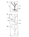
- FIG. It is a flowchart which shows the process position specific process in a wire harness manufacturing process. It is a figure for demonstrating a process position specific process. It is a figure for demonstrating a representative line acquisition process. It is a figure for demonstrating a hidden line acquisition process. It is a figure for demonstrating an attitude
- FIG. 1 is a schematic perspective view showing a measuring apparatus 1 according to the embodiment.
- the measuring device 1 is configured as a device that measures a three-dimensional shape of the wire assembly 9 and includes a stage 10, an imaging unit 20, and an image processing device 30.
- the electric wire assembly 9 to be measured in the measuring apparatus 1 includes a linear portion 91 composed of a plurality of electric wires, a connector 93 to which terminal portions of the plurality of electric wire groups are connected, and the like.
- the linear portion 91 may have a branch.
- the linear part 91 may contain things (for example, optical fiber cable etc.) other than an electric wire.
- a wire harness is manufactured by performing processing, such as binding and attachment of various members, with respect to a predetermined processing position. For example, as shown in FIG.
- the linear portion 91 of the wire assembly 9 is a portion where a plurality of electric wires are scattered in addition to a converging portion 910 in which a plurality of electric wires are previously converged into one by tape winding or the like.
- the electric wire dispersal part 911 which is may be included.
- the stage 10 is provided for placing the electric wire assembly 9 which is a measurement object. Instead of the stage 10, for example, the vicinity of each connector 93 of the wire assembly 9 may be held and the linear portion 91 may be held down.
- the imaging unit 20 includes a laser light irradiation unit 21 and a plurality of (here, four) cameras 23.
- Each of the plurality of cameras 23 includes a two-dimensional detector that detects the reflected light reflected from the wire assembly 9 by the laser light emitted from the laser light irradiation unit 21.
- a direction perpendicular to the imaging surfaces of the plurality of cameras 23 is referred to as “depth direction”, and an axis parallel to the depth direction is referred to as “Z axis”.
- Z axis an axis parallel to the depth direction
- two axes that are parallel to a two-dimensional plane perpendicular to the depth direction and are orthogonal to each other are referred to as an “X axis” and a “Y axis”, respectively.
- FIG. 2 is a block diagram illustrating a hardware configuration of the image processing apparatus 30 according to the embodiment.
- the image processing apparatus 30 includes a CPU 31 as a control unit, a read-only ROM 32 in which basic programs and the like are stored, a RAM 33 that is mainly used as a working area of the CPU 31, and a storage unit 34 that is a nonvolatile recording medium. I have.
- the image processing apparatus 30 is configured as a general computer.
- the storage unit 34 stores a program PG1.
- Various functions are realized by the CPU 31 as the seed control unit performing arithmetic processing according to the program PG1.
- the program PG1 may be normally stored in advance in a memory such as the storage unit 34, but is provided in a form (program product) recorded in a CD-ROM, DVD-ROM, or flash memory, and the recording medium May be read by the reading unit 35 and taken into the image processing apparatus 30.
- the program PG1 stored on the network may be taken into the image processing apparatus 30 via the communication unit 36.
- Other data may also be taken into the image processing apparatus 30 via the reading unit 35 or the communication unit 36.
- the image processing apparatus 30 is connected to the imaging unit 20, the display unit 41, and the operation unit 43 via a bus wiring, a network line, or a serial line.
- the display unit 41 is a device that displays an image such as a liquid crystal display.
- the operation unit 43 is an input device configured by, for example, a keyboard, a mouse, or switches, and accepts various operations from an operator.
- the operation unit 43 may be configured with a touch panel or the like. In this case, the touch panel may function as the display unit 41.
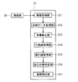
- FIG. 3 is a block diagram illustrating a software configuration of the image processing apparatus 30 according to the embodiment.
- the CPU 31 of the image processing apparatus 30 includes an image acquisition unit 311, a point cloud data acquisition unit 312, a background removal unit 313, a representative line acquisition unit 314, a hidden line acquisition unit 315, a processing position specification unit 316, and , Which functions as the posture specifying unit 317. Note that some or all of these functions may be realized in hardware by a dedicated circuit or the like.
- the image acquisition unit 311 processes a signal transmitted from the plurality of cameras 23 of the imaging unit 20 that captured the wire assembly 9 to acquire a plurality of image data.
- a plurality of pieces of image data may be acquired by processing data acquired by the imaging unit 20 with another computer or the like.
- a plurality of image data may be taken into the image processing apparatus 30 from the outside via the reading unit 35 or the communication unit 36 described above.
- the point cloud data acquisition unit 312 processes a plurality of image data acquired by the image acquisition unit 311 to acquire three-dimensional reflection point cloud data (hereinafter simply referred to as “point cloud data”).
- point cloud data three-dimensional reflection point cloud data
- the laser beam (reflected light) reflected by each part of the wire assembly 9 is reflected from the position of each point where the reflected light is incident on each two-dimensional detector of the plurality of cameras 23.
- the three-dimensional position information of each point in the aggregate 9 is acquired.
- the distance between the detection position in each camera 23 and each point of the wire assembly 9 is measured, thereby obtaining the three-dimensional position information of each point in the wire assembly 9. Is done.
- the point cloud data acquisition unit 312 acquires point cloud data related to the wire assembly 9.
- the imaging unit 20 is not limited to the above configuration, and any configuration may be adopted as long as the three-dimensional information of the wire assembly can be obtained. Note that it is not essential to acquire information such as a phase difference when acquiring point cloud data. However, by acquiring the phase difference information, the three-dimensional position information of each point on the surface of the wire assembly 9 can be acquired with high accuracy.
- the imaging unit 20 can also be configured with one light source and one camera. In this case, the three-dimensional position information of each point on the surface of the wire assembly 9 can be acquired from the irradiation direction of the laser light and the incident position on the detector in the camera.
- the background removal unit 313 is point cloud data acquired by the point cloud data acquisition unit 312 for point cloud data of only the background (here, corresponding to the surface of the stage 10 of the measuring device 1) excluding the wire assembly 9. Remove from.
- the background-only point cloud data is acquired by performing image processing on only the background image data obtained by the imaging unit 20 imaging only the stage 10 from which the wire assembly 9 is removed.
- the point group data of only the background may be acquired in advance and stored in the storage unit 34 or the like.
- the process of removing the background point cloud data can be realized, for example, by taking an XOR (exclusive OR) of the point cloud data including the wire assembly 9 and the background point cloud data.
- the point cloud data from which the background point cloud data has been removed will be referred to as the wire cloud 9 point cloud data.
- the representative line acquisition unit 314 acquires a representative line indicating the wire assembly 9 from the point cloud data of the wire assembly 9.
- the representative line is obtained by replacing the linear portion 91 of the wire assembly 9 with a single virtual line in accordance with the three-dimensional shape.
- the hidden line acquisition unit 315 compensates for the disconnection of the representative line portion by connecting two end portions within a predetermined distance among the end portions of the representative line acquired by the representative line acquisition unit 314.
- the hidden line acquisition unit 315 extends the representative line from each of the two ends along the tangential direction of each end. Even if a linear portion (hidden line) that is not detected as a representative line is generated by concealing the linear portion 91 of the wire assembly 9 by another member, the hidden line can be compensated.
- the shape of the wire assembly 9 can be specified assuming the hidden line of the linear portion 91, so that the processing position can be preferably specified.
- the representative line acquisition unit 314 has one wire from each wire included in the wire breakaway portion 911.
- the representative line is obtained. Note that a method of obtaining one representative line from the electric wire dispersal portion 911 will be described later.
- the wire scattering portions 911 in the wire assembly 9 are converged into one along the representative line.
- the wire assembly 99 in which the wire breaking portions 911 are concentrated is also referred to as a wire bundle.
- the processing position specifying unit 316 specifies a processing position that is a processing target position in the wire bundle based on the length along the representative line. Moreover, the process position specific
- the posture specifying unit 317 specifies the posture for attaching the member to the processing position specified by the processing position specifying unit 316. For example, in the clamp for fixing the wire harness to the vehicle body, the direction of the locking portion of the clamp in a state of being attached to the wire harness is determined in advance. For this reason, when attaching a clamp to an electric wire bundle, it is necessary to specify the attitude
- the posture specifying unit 317 specifies the posture of the member when the member is attached to the processing position.
- the posture specifying unit 317 includes a plurality of representative lines extending from each branch point at each of two branch points connected by the representative line among the branch points specified by the processing position specifying unit 316. Are obtained, and an angle formed by the two virtual surfaces is obtained. The angle formed by these two virtual planes indicates the degree of twist of the linear portion 91 of the wire bundle indicated by the representative line connecting the two branch points. For this reason, the attitude
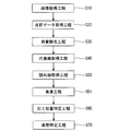
- FIG. 4 is a flowchart showing the processing position specifying process in the wire harness manufacturing process.
- the image acquisition unit 311 acquires image data (image acquisition step S10).
- the point cloud data acquisition unit 312 acquires point cloud data based on the image data acquired in the image acquisition step S10 (point cloud data acquisition step S20).
- the background removal part 313 acquires the point cloud data of the electric wire assembly 9 by removing background point cloud data from the point cloud data acquired in point cloud data acquisition process S20 (background removal process S30). ).
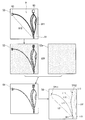
- FIG. 5 is a diagram for explaining the processing position specifying process.
- An image 50 illustrated in FIG. 5 is a visible light image captured by the camera 23.
- the image 52 is obtained by projecting the point cloud indicated by the point cloud data onto a two-dimensional plane (on the XY plane).
- the image 52a shows a point cloud indicated by point cloud data of only the background projected onto a two-dimensional plane.
- the background removal unit 313 performs XOR between the point cloud data indicated by the image 52 and the point cloud data indicated by the image 52a, whereby the wire assembly 9 shown in the image 54 is obtained. Point cloud data is acquired.
- the representative line acquisition unit 314 acquires a representative line indicating the wire assembly 9 (representative line acquisition step). S40).
- An example of the representative line acquisition step S40 will be described with reference to FIG.
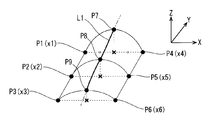
- FIG. 6 is a diagram for explaining the representative line acquisition step S40.
- the point cloud data of the wire assembly 9 three-dimensional position information about each point (points P1 to P9) on the surface of the wire assembly 9 is recorded as conceptually shown in FIG.
- Each point P1 to P9 shown in FIG. 6 is a point representatively showing a part of a point group on the surface of one wire constituting the linear portion 91 of the wire assembly 9.
- ⁇ P3 and points P4 ⁇ P6 correspond to the measurement contours of the linear portion 91 of the wire assembly 9, respectively.
- the representative line acquisition unit 314 acquires a point group on the contour among the point groups of the wire assembly 9 indicated by the point group data, and acquires a center point of the point group on the contour.
- the center point is a point at the center in the X-axis direction and the Y-axis direction with respect to the point group on the contour line.
- the outline of the wire assembly 9 in the point cloud data can be specified from the position in the depth direction of each point cloud indicated by the point cloud data. In this case, the position on the contour in the point cloud data can be specified by tracing the point on the farthest side (the direction away from the camera 23) within the predetermined range in the depth direction.
- the outline of the wire assembly 9 is acquired by image processing from a two-dimensional image (for example, the image 50) obtained by photographing with the camera 23, and the point cloud located at the position corresponding to the outline is obtained as the wire assembly 9. It is good also as a point cloud on the outline.
- the point groups of the wire assembly 9 indicated by the point group data are points P1 to P9, and the points P1 to P6 are specified as the point groups on the outline.
- the center points of the points P1 to P6 on the contour with respect to the X-axis direction and the Y-axis direction are specified.
- the center in the X-axis direction is the X-axis coordinates of the two points P1 and P4 (respectively , X1, x4)) (x1 + x4) / 2.
- the center point in the X-axis direction of the points P1 and P4 is a point P7 whose X-axis coordinates are (x1 + x4) / 2.
- the center point of points P2 and P5 is point P8, and the center point of points P3 and P6 is point P9.
- the center point in the Y-axis direction can be obtained in the same manner.
- the points P7 to P9 may be set as the center point.
- the radius of the corresponding part of the wire assembly 9 may be estimated from the points arranged along the X-axis direction (for example, points P1 and P4), and the center point may be determined in consideration of the radius. .
- the representative line acquisition unit 314 acquires a line connecting the center point groups (points P7 to P9) thus identified as the representative line L1. As shown in FIG. 5, the representative line acquisition unit 314 acquires the representative line shown in the image 56 from the point cloud data of the wire assembly 9 shown in the image 54.
- the representative line does not necessarily have to connect the center point of the point group located on the outline of the wire assembly 9.
- a point group arranged along the outline of the wire assembly 9 may be a representative line.
- the representative line approximated to the central line of the linear portion of the wire assembly 9 can be obtained by connecting the central points to the representative line. For this reason, the processing position in the linear part of the electric wire assembly 9 can be specified with high accuracy by measuring the length of the representative line.
- the representative line acquisition unit 314 acquires one representative line portion L 01 from the converging portion 910 in the wire assembly 9. Also, the representative line acquisition unit 314 extracts temporary representative lines (temporary representative lines L11, L12, L13, and L14) from each of the electric wires included in the electric wire distribution part 911 from the electric wire distribution part 911. Then, one representative line representing them is acquired. As an example, the representative line acquisition unit 314 acquires one center line passing through the centers of the temporary representative lines L11 to L14 as the representative line portion L02 in the three-dimensional space.
- whether or not the temporary representative lines L11 to L14 correspond to the respective electric wires of the electric wire dispersion portion 911 is, for example, within a specified radial distance of a specific temporary representative line of the temporary representative lines L11 to L14.
- the representative line acquisition unit 314 when another temporary representative line exists within the specified radial distance of the specific temporary representative line, the center of the three-dimensional space of the specific temporary representative line and the other temporary representative line. Is obtained as a new temporary representative line. Then, the representative line acquisition unit 314 detects another temporary representative line that is within the specified radial distance of the new temporary representative line, and if present, the center of the new temporary representative line and the other temporary representative line.
- the line is acquired as a new temporary representative line.
- the representative line acquisition unit 314 repeats such processing until another temporary representative line is not detected within the specified range.
- the representative line acquisition unit 314 can recognize a plurality of electric wires within a certain range as one electric wire scattered portion 911 and replace it with one representative line.
- one representative line when one representative line is acquired from the temporary representative lines L11 to L14, one representative line may be acquired from some of the temporary representative lines. For example, it is conceivable that one temporary representative line on the innermost side is specified, and this is used as one representative line indicating the electric wire dispersion portion 911. Alternatively, it is also conceivable that, among the temporary representative lines L11 to L14, a center line is specified from two or more temporary representative lines inside, and one representative line is acquired from these temporary representative lines.
- the hidden line acquisition unit 315 has two ends within a predetermined distance among the respective ends of the plurality of representative lines acquired by the representative line acquisition unit 314. Are connected (hidden line acquisition step S50).
- the hidden line acquisition step S50 will be specifically described with reference to FIG.
- FIG. 7 is a diagram for explaining the hidden line acquisition step S50.
- An image 50 a illustrated in FIG. 7 is an image acquired by the image acquisition unit 311.
- another member 94 overlaps the linear portion 91a of the wire assembly 9a, which is a hidden line.
- the representative line corresponding to the linear portion 91a is divided into the representative line portion L20 and the representative line portion L21.
- the hidden line acquisition unit 315 identifies two end points within a predetermined distance among all end points of the representative line, and extends each representative line portion from the two end points in the tangential direction. This connects the two end points. For example, assuming that the end points TP1 and TP2 of the representative line portions L20 and L21 shown in FIG. 7 are within a predetermined distance, the respective representative line portions L20 and L21 are extended in the tangential direction from the end points TP1 and TP2. Connecting. As a result, the hidden line generated when the linear portion 91a overlaps the other member 94 can be compensated as shown in the image 56b.
- the electric wires in the electric wire dispersion portion 911 are converged so as to follow the representative line supplemented with the hidden lines (the converging step S51). As a result, a wire bundle is formed from the wire assembly 9. Note that when the electric wire assembly 9 does not have the electric wire scattering portion 911, the focusing step S51 is skipped.
- the processing position specifying unit 316 specifies the processing position in the wire bundle (processing position specifying step S60).
- processing position specifying step S60 first, a branch point is specified.
- a branch point is specified.
- the representative line L1 indicating the linear portion 91 of the wire assembly 9 is acquired, and the terminals TP11 and TP12 of the representative line L1 are specified.
- the terminals TP11 and TP12 correspond to terminal portions of linear portions connected to the connector 93.
- the representative line portions L01 and L02 corresponding to the linear portion are traced, and a point joining the other representative line portions is defined as a branch point.
- a point joining the other representative line portions is defined as a branch point.
- the representative line portion L01 is traced from the terminal TP11, the representative line portion L01 merges with another representative line portion L02. For this reason, this junction is specified as branch point DP1.
- a point where the representative line portion L03 joins another representative line portion is also specified as a branch point. In this way, all branch points on the representative line L1 are specified.
- the processing position specifying unit 316 specifies the processing position by measuring the length along the representative line extending from each branch point.
- the processing position in the wire bundle is stored in advance in the storage unit 34 as design data.
- the design data defines the length of the linear portion 91 from each branch point to another branch point or terminal in the wire bundle. For example, in the case of the wire bundle design data shown in FIG. 5, the length from the branch point DP1 to the terminals TP11 and TP12 is defined on the design data.
- the machining position of each linear portion 91 is defined by the length from the branch point (or terminal).
- the processing position specifying unit 316 specifies the representative line portion to be processed by referring to the design data, and specifies the processing position on the representative line portion, the length from the branch point (or terminal), It is specified by measuring along the representative line portion.
- the machining position specifying step S60 it is executed in the hidden line acquisition step S50 by collating information on the branch points registered in the design data with information on the branch points obtained by actual three-dimensional measurement.
- the image processing apparatus 30 may be configured to determine whether or not the acquisition of hidden lines is appropriate. Further, by collating the information on the branch point, image processing is performed so that it is possible to estimate whether or not the other member causing the disconnection of the representative line portion is the other linear portion 91 of the wire bundle.
- the device 30 may be configured.
- the image processing device 30 identifies the branch point information actually specified by the processing position specifying unit 316 and the branch point information defined in advance in the design data, so that it is specified in the line break acquisition step. It is possible to acquire hidden lines that did not exist.
- the posture specifying unit 317 specifies the mounting posture of a member whose mounting posture with respect to the wire bundle such as a clamp is defined in advance (posture specifying step S70).
- the posture specifying step S70 will be described with reference to FIG.
- FIG. 8 is a diagram for explaining the posture specifying step S70.
- the posture specifying unit 317 includes, for each of two branch points connected by one representative line among the branch points specified by the machining position specifying unit 316, a plurality of representative lines extending from the two branch points. Two virtual planes to be formed are acquired. Then, the posture specifying unit 317 acquires the torsion of the representative line connecting the two branch points based on the angle formed by the two virtual surfaces. The posture specifying unit 317 specifies the mounting posture of the member to be mounted according to the twist of the representative line portion.
- the representative line portions L31 to L35 indicating the linear portion 91 of the wire bundle and the branch points DP21 and DP22 have already been specified, and the clamp 95 is located at the processing position PL1 of the representative line portion L31.
- the posture specifying unit 317 includes a plurality of representative line portions (representative line portions L31, L32, L33, and the like) extending from each of the branch points DP21 and DP22 connected by the representative line portion L31.
- the virtual planes VP1 and VP2 formed by the representative line portions L31, L34, and L35) are acquired.
- the virtual planes VP1 and VP2 for example, with respect to the branch point DP21, a plane passing through points (for example, P21, P22, and P23) at a certain distance on the representative line portions L31, L32, and L33 from the branch point DP21. Is a virtual plane VP1. The same applies to the virtual plane VP2.
- the posture specifying unit 317 acquires the angle formed by the virtual surfaces VP1 and VP2, and specifies the mounting posture of the clamp 95 based on the angle.
- the angle formed by the virtual surface VP2 with respect to the virtual surface VP1 is different from the reference angle defined in the design data, it is estimated that the representative line portion L31 is twisted more than expected. For this reason, the attachment posture of the clamp 95 may be inclined by an amount corresponding to the twist. For example, it is assumed that the actual angle of the virtual surface VP2 and the reference angle differ from the virtual surface VP1 by ⁇ degrees around the X axis and ⁇ degrees around the Y axis.
- the ratio of the length from the branch point DP21 to the machining position PL1 to the length from the branch point DP21 to the branch point DP22 (that is, the length of the representative line portion L31) is R1.
- the mounting posture of the clamp 95 may be inclined about the X axis and the Y axis from the reference posture by an angle obtained by multiplying each of ⁇ and ⁇ by R1.
- a robot (not shown) performs various processing (tape winding or binding) on the specified processing position of the wire bundle. Bonding by band attachment or the like, attachment of a clamp, or attachment of a protective member such as a tube) is appropriately performed. Note that an operator may appropriately perform a machining operation on the identified machining position. Thus, a wire harness is manufactured from the unprocessed electric wire assembly 9 according to the design data.
- the processing position can be specified with high accuracy.
- the background removal unit 313 shown in FIG. 3 and the background removal step S30 shown in FIG. 4 can be omitted. That is, a representative line can be appropriately extracted from point cloud data having background point cloud data.
- the calculation burden on the image processing apparatus 30 can be significantly reduced. For this reason, image processing can be performed at high speed.
Landscapes
- Physics & Mathematics (AREA)
- General Physics & Mathematics (AREA)
- Engineering & Computer Science (AREA)
- Computer Vision & Pattern Recognition (AREA)
- Manufacturing & Machinery (AREA)
- Length Measuring Devices By Optical Means (AREA)
- Image Processing (AREA)
- Image Analysis (AREA)
Abstract
線形状物の形状計測に好適な技術を提供する。ワイヤーハーネスを製造する過程において、電線集合体9の三次元形状が測定されることによって加工位置が特定される加工位置特定処理が実施される。この加工位置特定処理は、電線集合体9を撮像部20によって撮影して得られた画像データから、点群データを取得する点群データ取得工程S20と、点群データに基づいて、電線集合体9の線状部分91を示す代表線を取得する代表線取得工程S40と、代表線に沿った長さに基づいて、電線集合体9における加工対象である加工位置を特定する加工位置特定工程S60とを含む。
Description
この発明は、ワイヤーハーネスの三次元形状を計測する技術に関する。
近年、ワイヤーハーネス製造の自働化の試みがなされている。ワイヤーハーネス製造を自働化する上で、柔軟な線形状物において、加工すべき位置を特定することが重要な課題となっている。
例えば特許文献1では、レーザー光発生器で発生したレーザー光を、複数のスリット光からなるパターン光に変換し、それをケーブルに当てることによって発生する複数の輝点を特徴点として抽出している。
また、特許文献2では、ワークの画像が撮影して得られた元画像を2値化し、エッジを抽出する。一方で、2値化画像を膨張処理して、ワークに対応する膨張領域の境界線上に複数の基準点を設定する。そして、全基準点毎に最短距離にある上記エッジを特定し、それらのエッジを連結していくことによって、元のワークの輪郭線が抽出される。
しかしながら、特許文献1に記載の技術の場合、ケーブルが移動した際に輝点の位置が変わってしまう。このため、柔軟物加工時の形状計測を行うには不向きであった。また、特許文献2に記載の技術の場合、エッジの抽出および照合を行うために、多数の点についてデータ処理を行う必要があり、演算処理に時間を要していた。
特に、複数の電線の集線および形状形成を自働化するためには、線形状物の各部の位置または特定部位間の長さを計測することが要求されており、これに適した形状計測技術が求められていた。
そこで、本発明は、線形状物の形状計測に好適な技術を提供することを目的とする。
上記の課題を解決するため、第1の態様は、ワイヤーハーネスの製造方法であって、電線集合体を撮像部によって撮影して得られた画像データから、点群データを取得する点群データ取得工程と、前記点群データに基づいて、前記電線集合体の線状部分を示す代表線を取得する代表線取得工程と、前記代表線に沿った長さに基づいて、前記電線集合体における加工対象である加工位置を特定する加工位置特定工程とを含む。
また、第2の態様は、第1の態様に係るワイヤーハーネスの製造方法であって、前記加工位置特定工程は、前記代表線が分岐する分岐点を特定し、特定された前記分岐点からの前記代表線に沿った長さに基づいて、前記加工位置を特定する工程を含む。
また、第3の態様は、第2の態様に係るワイヤーハーネスの製造方法であって、前記分岐点のうち、前記代表線の一部である代表線部分で接続されている2つの分岐点のそれぞれにおいて、当該2つの分岐点のそれぞれから延びる複数の代表線部分が成す2つの仮想面を取得し、当該2つの仮想面が成す角度に基づいて、前記2つの分岐点を接続する前記代表線に取り付ける部材の姿勢を特定する姿勢特定工程、をさらに含む。
また、第4の態様は、第1から第3の態様のいずれか1態様に係るワイヤーハーネスの製造方法であって、前記代表線取得工程は、前記点群データに基づき、前記電線集合体の線状部分の中心点群を特定し、当該中心点群を結ぶ線を前記代表線とする工程である。
また、第5の態様は、第4の態様に係るワイヤーハーネスの製造方法であって、前記中心点群が、前記点群データが示す前記電線集合体の輪郭上に位置する点群のうち、奥行き方向に直交する二方向に関して中心にある中心点の集合である。
また、第6の態様は、第1から第5の態様のいずれか1態様に係るワイヤーハーネスの製造方法であって、前記点群データ取得工程で得られた点群データから、前記電線集合体を除いた背景を前記撮像部によって撮影することによって得られる背景の点群データを除去する背景除去工程、をさらに含み、前記代表線取得工程は、前記背景の点群データが除去された点群データに基づいて、前記代表線を取得する工程である。
また、第7の態様は、第1から第6の態様のいずれか1態様に係るワイヤーハーネスの製造方法であって、前記代表線取得工程にて取得された代表線の各端部のうち、所定の距離内にある2つの端部を接続する隠れ線接続工程、をさらに含む。
また、第8の態様は、第1から第7の態様のいずれか1態様に係るワイヤーハーネスの製造方法であって、前記撮像部は、前記電線集合体の各点に照射されたレーザー光と、当該各点で反射した前記レーザー光との位相差を、複数の二次元検出器で検出する。
また、第9の態様は、画像処理方法であって、電線集合体を撮像部によって撮影して得られた画像データから、点群データを取得する点群データ取得工程と、前記点群データに基づいて、前記電線集合体を示す代表線を取得する代表線取得工程と、前記代表線に沿った長さに基づいて、前記電線集合体における加工対象である加工位置を特定する加工位置特定工程とを含む。
第1の態様によると、電線集合体の線状部分を示す代表線を抽出することで、電線集合体の三次元形状を容易に計測でき、かつ、加工位置を高精度に特定できる。
また、第2の態様によると、分岐点からの長さに基づいて、加工位置を特定することが可能となる。
また、第3の態様によると、2つの分岐点における仮想面の成す角度から、当該2つの分岐点を接続する電線集合体部分のねじれを特定できる。したがって、そのねじれに合わせて、部材の取り付ける際の取付姿勢を、適切に特定できる。
また、第4の態様によると、点群データにおける電線集合体の中心点群を特定し、これを結ぶ線を代表線とすることによって、電線集合体の線状部分の三次元形状を高精度に特定できる。これによって、加工位置を高精度に特定できる。
また、第5の態様によると、電線集合体の線状部分の中心線を精度良く取得できる。
また、第6の態様によると、点群データから背景の点群データを除去することによって、演算処理量を低減できる。
また、第7の態様によると、電線集合体の線状部分が他の部材に隠されること等によって、代表線に線切れが発生したとしても、これを接続できる。このため、隠れ線を仮想して、電線集合体の形状を良好に特定できる。
また、第8の態様によると、電線集合体の各点の位置を高精度に測定できる。したがって、電線集合体の形状を高精度に特定できる。
以下、添付の図面を参照しながら、本発明の実施形態について説明する。なお、この実施形態に記載されている構成要素はあくまでも例示であり、本発明の範囲をそれらのみに限定する趣旨のものではない。また、図面においては、理解容易のため、必要に応じて各部の寸法や数が誇張または簡略化して図示されている場合がある。
<1. 実施形態>
図1は、実施形態に係る計測装置1を示す概略斜視図である。計測装置1は、電線集合体9について、三次元形状の測定を行う装置として構成されており、ステージ10、撮像部20、画像処理装置30を備えている。
図1は、実施形態に係る計測装置1を示す概略斜視図である。計測装置1は、電線集合体9について、三次元形状の測定を行う装置として構成されており、ステージ10、撮像部20、画像処理装置30を備えている。
この計測装置1において測定対象となる電線集合体9は、複数の電線で構成される線状部分91と、複数の電線群の端末部分が接続されるコネクタ93等を備えている。線状部分91は、分岐を有していてもよい。また、線状部分91は、電線以外のもの(例えば、光ファイバーケーブルなど)を含んでいてもよい。この電線集合体9について、所定の加工位置に対して結束、各種部材の取り付け等の加工が施されることによって、ワイヤーハーネスが製造される。電線集合体9の線状部分91は、例えば図1に示すように、複数本の電線が予めテープ巻き等で1本に集束されている集束部分910の他に、複数の電線がばらけた部分である電線ばらけ部分911が含まれていてもよい。
ステージ10は、測定対象物である電線集合体9を載置するために設けられている。なお、ステージ10の代わりに、例えば、電線集合体9の各コネクタ93付近を保持して、線状部分91を垂らすようにして保持してもよい。
撮像部20は、レーザー光照射部21と、複数(ここでは、4台)のカメラ23とを備えている。複数のカメラ23のそれぞれは、レーザー光照射部21から出射されたレーザー光が、電線集合体9で反射した反射光を検出する二次元検出器を備えている。
なお、以下の説明では、複数のカメラ23の撮影面(二次元検出器の検出面)に垂直な方向を「奥行き方向」とし、当該奥行き方向に平行な軸を「Z軸」とする。また、当該奥行き方向に垂直な二次元平面に平行であって、互いに直交する2方向の軸を、それぞれ「X軸」、「Y軸」とする。
図2は、実施形態に係る画像処理装置30のハードウェア構成を示すブロック図である。画像処理装置30は、制御部としてのCPU31、基本プログラム等が格納されている読み取り専用のROM32、主にCPU31のワーキングエリアとして使用されるRAM33、及び、不揮発性の記録媒体である記憶部34を備えている。このように、画像処理装置30は、一般的なコンピュータとして構成されている。
記憶部34には、プログラムPG1が格納されている。該プログラムPG1に従って、種制御部としてのCPU31が演算処理を行うことによって、各種機能が実現される。また、プログラムPG1は、通常、予め記憶部34等のメモリに格納されていてもよいが、CD-ROM、DVD-ROMまたはフラッシュメモリに記録された形態(プログラムプロダクト)で提供され、当該記録媒体を読取部35で読み取って、画像処理装置30に取り込まれるようにしてもよい。あるいは、通信部36を介して、ネットワーク上に保存されたプログラムPG1が、画像処理装置30に取り込まれてもよい。その他のデータについても、読取部35または通信部36を介して、画像処理装置30に取り込まれるようにしてもよい。
また、画像処理装置30は、撮像部20、表示部41及び操作部43にバス配線、ネットワーク回線またはシリアル回線を介して接続されている。表示部41は、液晶ディスプレイなどの画像を表示する装置である。操作部43は、例えば、キーボード、マウスまたはスイッチ類によって構成される入力デバイスであり、オペレータからの各種操作を受け付ける。なお、操作部43は、タッチパネルなどで構成されていてもよい。この場合、当該タッチパネルが、表示部41として機能するようにしてもよい。
図3は、実施形態に係る画像処理装置30のソフトウェア構成を示すブロック図である。図3に示すように、画像処理装置30のCPU31は、画像取得部311、点群データ取得部312、背景除去部313、代表線取得部314、隠れ線取得部315、加工位置特定部316、及び、姿勢特定部317として機能する。なお、これらの機能の一部または全部は、専用の回路等によってハードウェア的に実現されてもよい。
画像取得部311は、電線集合体9を撮影した撮像部20の複数台のカメラ23から送られてくる信号をそれぞれ処理して、複数の画像データを取得する。なお、撮像部20で撮影して得たデータが、他のコンピュータ等で処理されることによって、複数の画像データが取得されてもよい。この場合、複数の画像データが、上述の読取部35または通信部36を介して、外部から画像処理装置30に取り込まれるようにしてもよい。
点群データ取得部312は、画像取得部311によって取得された複数の画像データを処理して、三次元反射点群データ(以下、単に「点群データ」と称する。)を取得する。本実施形態では、電線集合体9の各部分で反射したレーザー光(反射光)が、複数のカメラ23のそれぞれの二次元検出器に入射した各点の位置から、当該反射光が反射した電線集合体9における各点の三次元位置情報が取得される。また、照射光と反射光の位相差に基づいて、各カメラ23における検出位置と電線集合体9の各点の距離を計測することによって、電線集合体9における各点の三次元位置情報が取得される。これらの三次元位置情報に基づき、点群データ取得部312は、電線集合体9に関する点群データを取得する。
撮像部20は、上記構成に限定されるものではなく、電線集合体の三次元情報を得ることができればどのような構成が採用されてもよい。なお、点群データを取得する上では、位相差等の情報を取得することは必須ではない。しかしながら、当該位相差情報を取得することによって、電線集合体9の表面上の各点の三次元位置情報を高精度に取得できる。また、撮像部20は、1台の光源と、1台のカメラで構成することもできる。この場合、レーザー光の照射方向と、カメラにおける検出器への入射位置とから、電線集合体9の表面上の各点の三次元位置情報を取得できる。
背景除去部313は、電線集合体9を除いた背景(ここでは、計測装置1のステージ10の表面に相当する。)のみの点群データを、点群データ取得部312が取得した点群データから除去する。背景のみの点群データは、電線集合体9が除かれたステージ10のみを撮像部20が撮像して得られた背景のみの画像データを、画像処理することによって取得される。背景のみの点群データは、例えば、予め取得されて、記憶部34等に格納されていてもよい。背景の点群データを除去する処理は、例えば、電線集合体9を含む点群データと、背景のみの点群データとのXOR(エクスクルーシブ・オア)をとることによって実現できる。なお、以下の説明では、この背景のみの点群データが除去された点群データを、電線集合体9の点群データと称する。
代表線取得部314は、電線集合体9の点群データから、電線集合体9を示す代表線を取得する。代表線は、電線集合体9の線状部分91を、その三次元形状に合わせて、1本の仮想的な線に置換したものとして取得される。
隠れ線取得部315は、代表線取得部314によって取得された代表線の各端部のうち、所定の距離内にある2つの端部を接続することによって、代表線部分の線切れを補う。一例として、隠れ線取得部315は、2つの端部のそれぞれから、各端部の接線方向に沿って代表線を延長する。仮に、電線集合体9の線状部分91が他の部材に隠されること等によって、代表線として検出されない線状部分(隠れ線)が発生したとしても、当該隠れ線を補うことができる。このように隠れ線を補っておくことによって、線状部分91の隠れ線を想定して電線集合体9の形状を特定できるため、加工位置を好適に特定できる。
図1に示すように、電線集合体9の線状部分91において、電線ばらけ部分911が存在する場合、代表線取得部314は、当該電線ばらけ部分911に含まれる各電線から、1本の代表線を取得するように構成されている。なお、電線ばらけ部分911から1本の代表線を取得する方法については後述する。
代表線取得部314及び隠れ線取得部315によって、電線集合体9を表す代表線が取得されると、電線集合体9における電線ばらけ部分911が当該代表線に沿って1本に集束される。なお、以下の説明では、電線ばらけ部分911が集束された電線集合体99を、電線束とも称する。
加工位置特定部316は、代表線に沿った長さに基づいて、電線束における加工対象の位置である加工位置を特定する。また、加工位置特定部316は、電線束の線状部分91を示す代表線の端部(例えば、コネクタ93f線と合流する地点を、分岐点とする。加工位置特定部316は、特定された分岐点からの代表線に沿った距離を測定して、加工位置を特定する。
姿勢特定部317は、加工位置特定部316によって特定された加工位置に対して、部材を取り付ける姿勢を特定する。例えば、ワイヤーハーネスを車両のボディに固定するためのクランプなどは、ワイヤーハーネスに取り付けられた状態におけるクランプの係止部分の向きが予め決められている。このため、クランプを電線束に取り付ける場合には、電線束に対するクランプの姿勢を特定する必要がある。姿勢特定部317は、加工位置に対して部材を取り付ける際の、当該部材の姿勢を特定する。
具体的には、姿勢特定部317は、加工位置特定部316によって特定された分岐点のうち、代表線で接続されている2つの分岐点のそれぞれにおいて、各々の分岐点から延びる複数の代表線が成す仮想面をそれぞれ取得し、当該2つの仮想面が成す角度を取得する。この2つの仮想面が成す角度は、2つの分岐点を接続する代表線が示す電線束の線状部分91のねじれ度合いを示している。このため、当該角度から、電線束の線状部分91に対して取り付ける際の姿勢を好適に決定できる。
<ワイヤーハーネスの製造方法>
図4は、ワイヤーハーネス製造過程における、加工位置特定処理を示すフローチャートである。まず画像取得部311が、画像データを取得する(画像取得工程S10)。続いて、点群データ取得部312が、画像取得工程S10にて取得された画像データに基づき、点群データを取得する(点群データ取得工程S20)。そして、背景除去部313が、点群データ取得工程S20において取得された点群データから、背景の点群データを除去することによって、電線集合体9の点群データを取得する(背景除去工程S30)。
図4は、ワイヤーハーネス製造過程における、加工位置特定処理を示すフローチャートである。まず画像取得部311が、画像データを取得する(画像取得工程S10)。続いて、点群データ取得部312が、画像取得工程S10にて取得された画像データに基づき、点群データを取得する(点群データ取得工程S20)。そして、背景除去部313が、点群データ取得工程S20において取得された点群データから、背景の点群データを除去することによって、電線集合体9の点群データを取得する(背景除去工程S30)。
図5は、加工位置特定処理を説明するための図である。図5に示す画像50は、カメラ23が撮影した可視光画像である。
画像52は、点群データが示す点群を、二次元平面(XY平面上)に投影したものである。また、画像52aは、背景のみの点群データが示す点群を、二次元平面に投影して示すものである。背景除去工程S30では、上述したように、背景除去部313が、画像52が示す点群データと、画像52aが示す点群データとのXORをとることによって、画像54に示す電線集合体9の点群データが取得される。
図4に戻って、背景除去工程S30にて取得された電線集合体9の点群データに基づいて、代表線取得部314が、電線集合体9を示す代表線を取得する(代表線取得工程S40)。代表線取得工程S40の一例について、図6を参照しつつ説明する。
図6は、代表線取得工程S40を説明するための図である。電線集合体9の点群データには、図6に概念的に示すように、電線集合体9の表面の各点(点P1~P9)についての三次元位置情報が記録されている。なお、図6に示す各点P1~P9は、電線集合体9の線状部分91を構成する1本の電線の表面上の点群の一部を代表的に示した点であり、点P1~P3及び点P4~P6は、それぞれ、電線集合体9の線状部分91の計測上の輪郭に相当する。
代表線取得部314は、点群データが示す電線集合体9の点群のうち、輪郭上の点群を取得し、当該輪郭上の点群の中心点を取得する。この中心点は、具体的には、輪郭線上の点群に対して、X軸方向及びY軸方向の中心にある点とされる。また、点群データにおける電線集合体9の輪郭は、点群データが示す各点群の奥行き方向の位置などから特定できる。この場合、奥行き方向の所定範囲内において、最も奥側(カメラ23から遠ざかる方向側)にある点を辿っていくことによって、点群データにおける輪郭上の位置を特定できる。あるいは、カメラ23によって撮影して得た二次元画像(例えば、画像50)から、画像処理によって電線集合体9の輪郭を取得し、この輪郭に対応する位置にある点群を、電線集合体9の輪郭上の点群としてもよい。
例えば、図6に示す例の場合、点群データが示す電線集合体9の点群は、点P1~P9であり、その輪郭上の点群として、点P1~P6が特定される。続いて、輪郭上の点P1~P6の、X軸方向及びY軸方向に関する中心点が特定される。点P1及び点P4がX軸方向に沿って並んでいる(すなわち、点P1,P4のY座標が同一)とすると、X軸方向の中心は、2つの点P1,P4のX軸座標(それぞれ、x1,x4とする。)の平均値(x1+x4)/2となる。このため、点P1,P4のX軸方向の中心点は、X軸座標が(x1+x4)/2である点P7となる。同様に、点P2,P5の中心点は点P8であり、点P3,P6の中心点は点P9となる。図示を省略するが、Y軸方向に関する中心点も同様にして取得することが可能である。
電線集合体9のうち、上半面のみの点群データしか取得されない。そこで、Y軸方向については、点P7~点P9を中心点としてもよい。また、X軸方向に沿って並ぶ点(例えば、点P1,P4)から、電線集合体9の該当部分の半径を推定し、その分を考慮して中心点が決定されるようにしてもよい。
代表線取得部314は、こうして特定された中心点群(点P7~点P9)を結ぶ線を代表線L1として取得する。図5に示すように、代表線取得部314によって、画像54に示す電線集合体9の点群データから、画像56に示す代表線が取得される。
なお、代表線は、上述したように、必ずしも電線集合体9の輪郭上に位置する点群の中心点を結んだものでなくてもよい。例えば、電線集合体9の輪郭に沿って並ぶ点群が代表線とされてもよい。しかしながら、中心点を結んで代表線とすることによって、電線集合体9の線状部分の中心線に近似した代表線を取得できる。このため、代表線の長さを測定することによって、電線集合体9の線状部分における加工位置を高精度に特定できる。
図5に示す例では、画像56に示すように、代表線取得部314は、電線集合体9のうち集束部分910から1本の代表線部分L01を取得する。また、代表線取得部314は、電線ばらけ部分911からは、当該電線ばらけ部分911に含まれる各電線のそれぞれから、仮の代表線(仮代表線L11,L12,L13,L14)を抽出し、それらを代表する1本の代表線を取得する。一例として、代表線取得部314は、三次元空間において、仮代表線L11~L14の中心を通る1本の中心線を、代表線部分L02として取得する。
なお、仮代表線L11~L14が、電線ばらけ部分911の各電線に相当するかどうかは、例えば、仮代表線L11~L14のうちの特定の仮代表線の規定半径距離内において、他の仮代表線を検出することで判別してもよい。一例として、代表線取得部314は、特定の仮代表線の規定半径距離内に他の仮代表線が存在する場合には、特定の仮代表線と他の仮代表線の三次元空間の中心を通る中心線を、新たな仮代表線として取得する。そして、代表線取得部314は、当該新たな仮代表線の規定半径距離内にある他の仮代表線を検出し、存在する場合には、当該新たな仮代表及び他の仮代表線の中心線を、新たな仮代表線として取得する。このような処理を、代表線取得部314は、規定範囲内に別の仮代表線が検出されなくなるまで繰り返す。これによって、代表線取得部314は、一定範囲内にある複数の電線を1電線ばらけ部分911として認識し、1本の代表線に置換することができる。
また、例えば仮代表線L11~L14から1本の代表線を取得する際、これらのうち一部の仮代表線から一本の代表線を取得することも考えられる。例えば、最も内側にある1本の仮代表線を特定し、これを電線ばらけ部分911を示す1本の代表線とすることも考えられる。あるいは、仮代表線L11~L14のうち、内側にある2本以上の仮代表線から中心線を特定し、これらの仮代表線から1本の代表線を取得することも考えられる。
図4に戻って、代表線取得工程S40が完了すると、隠れ線取得部315が、代表線取得部314によって取得された複数の代表線の各端部のうち、所定の距離内にある2つの端部を接続する(隠れ線取得工程S50)。隠れ線取得工程S50について、図7を参照しつつ具体的に説明する。
図7は、隠れ線取得工程S50を説明するための図である。図7に示す画像50aは、画像取得部311によって取得された画像である。この例では、電線集合体9aの線状部分91aに、他の部材94が重なっており、隠れ線となっている。このため、画像56aに示すように、代表線取得部314が取得した代表線のうち、線状部分91aに対応する代表線が、代表線部分L20と代表線部分L21とに分断されている。
隠れ線取得部315は、代表線の全ての端点のうち、所定の距離内にある2つの端点を特定し、その2つの端点から各々の代表線部分を接線方向に延長する。これによって、2つの端点間を接続する。例えば、図7に示す代表線部分L20,L21の端点TP1,TP2が所定の距離内にあると仮定すると、端点TP1,TP2から、それぞれの代表線部分L20,L21をその接線方向に延長して接続する。これによって、線状部分91aが他の部材94に重なることで発生する隠れ線を、画像56bに示すように補うことができる。
図4に戻って、隠れ線取得工程S50が完了すると、電線ばらけ部分911の各電線が、隠れ線が補われた代表線に沿うように、集束される(集束工程S51)。これによって、電線集合体9から電線束が形成される。なお、電線集合体9に電線ばらけ部分911が存在しない場合には、当該集束工程S51はスキップされる。
電線束が形成されると、加工位置特定部316が、電線束における加工位置を特定する(加工位置特定工程S60)。加工位置特定工程S60では、まず、分岐点の特定が行われる。ここで、分岐点の特定方法の一例を説明する。例えば、図5の画像56に示すように、電線集合体9の線状部分91を示す代表線L1が取得されており、この代表線L1の端末TP11,TP12が特定される。この端末TP11,TP12は、コネクタ93に接続する線状部分の端末部分に対応している。端末TP11,TP12のそれぞれから、線状部分に対応する代表線部分L01,L02上を辿っていき、他の代表線部分に合流した地点を分岐点とする。例えば、端末TP11から代表線部分L01を辿っていくと、当該代表線部分L01は、他の代表線部分L02に合流する。このため、この合流地点が分岐点DP1として特定される。なお、分岐点DP1からさらに代表線部分L03を辿って行くことで、当該代表線部分L03が他の代表線部分に合流する地点も分岐点として特定される。このようにして、代表線L1上の全ての分岐点が特定される。
加工位置特定部316は、各分岐点を特定すると、各分岐点から延びる代表線に沿う長さを測定して、加工位置を特定する。ここで、電線束における加工位置は、予め、設計データとして記憶部34等に保存されている。具体的に、設計データには、電線束における、各分岐点から別の分岐点、または、端末までの線状部分91の長さが、規定されている。例えば、図5に示す電線束の設計データの場合は、分岐点DP1から端末TP11,TP12までの長さが設計データ上で定義される。
また、設計データでは、各線状部分91の加工位置が、分岐点(または端末)からの長さで定義される。加工位置特定部316は、設計データを参照することによって、加工対象となる代表線部分を特定し、かつ、その代表線部分上における加工位置を、分岐点(または端末)からの長さを、当該代表線部分に沿って測定することよって特定する。
また、加工位置特定工程S60においては、設計データに登録されている分岐点の情報と、実際の三次元測定によって得られた分岐点の情報とを照合することによって、隠れ線取得工程S50で実行された隠れ線の取得が妥当であったか否かを判定するように、画像処理装置30が構成されてもよい。また、分岐点の情報を照合することによって、代表線部分の線切れの原因となった他の部材が、電線束の他の線状部分91であるか否かを推定できるように、画像処理装置30が構成されてもよい。
また、画像処理装置30が、加工位置特定部316が実際に特定した分岐点の情報と、予め設計データに定義された分岐点の情報とを照合することで、上記線切れ取得工程では特定されなかった隠れ線を取得することが可能となる。
図4に戻って、加工位置特定工程S60が完了すると、姿勢特定部317が、クランプなどの電線束に対する取り付け姿勢が予め規定されている部材の取り付け姿勢を特定する(姿勢特定工程S70)。姿勢特定工程S70について、図8を参照しつつ説明する。
図8は、姿勢特定工程S70を説明するための図である。姿勢特定部317は、加工位置特定部316によって特定された分岐点のうち、1本の代表線で接続されている2つの分岐点のそれぞれについて、当該2つの分岐点から延びる複数の代表線が成す2つの仮想面をそれぞれ取得する。そして、姿勢特定部317は、2つの仮想面が成す角度に基づいて、2つの分岐点を接続する代表線のねじれを取得する。姿勢特定部317は、この代表線部分のねじれに応じて、取り付ける部材の取付姿勢を特定する。
例えば、図8に示すように、電線束の線状部分91を示す代表線部分L31~L35、分岐点DP21,DP22が既に特定されており、代表線部分L31の加工位置PL1に、クランプ95が取り付ける場合を想定する。この場合、姿勢特定部317は、代表線部分L31で接続されている分岐点DP21,DP22の各々において、当該分岐点のそれぞれから延びる複数の代表線部分(代表線部分L31,L32,L33、及び、代表線部分L31,L34,L35)が成す仮想面VP1,VP2が取得される。なお、仮想面VP1,VP2については、例えば分岐点DP21については、当該分岐点DP21から各代表線部分L31,L32,L33上の一定距離にある点(例えば、P21,P22,P23)を通る面が、仮想面VP1とされる。仮想面VP2についても同様である。
続いて、姿勢特定部317は、仮想面VP1,VP2が成す角度を取得し、その角度に基づいて、クランプ95の取付姿勢を特定する。仮想面VP1に対して仮想面VP2の成す角度が、設計データで既定された基準角度と相違する場合、代表線部分L31が想定よりもねじれていると推定される。このため、クランプ95の取付姿勢を、そのねじれに応じた分だけ傾ければよい。例えば、仮想面VP1に対して仮想面VP2の実際の角度と、基準角度とが、X軸周りにα度、Y軸周りにβ度相違するとする。また、分岐点DP21から分岐点DP22までの長さ(すなわち、代表線部分L31の長さ)に対する、分岐点DP21から加工位置PL1までの長さの割合をR1とする。この場合、クランプ95の取付姿勢を、α及びβのそれぞれにR1を乗じた角度分、基準姿勢からX軸、Y軸周りにそれぞれ傾ければよい。
以上のように、加工位置の特定、あるいは、部材の取付姿勢が特定されると、図示を省略するロボットなどが、特定された電線束の加工位置に対して、各種加工処理(テープ巻または結束バンド取り付け等による結束、クランプの取り付け、またはチューブなどの保護部材の取り付け等)が適宜行われる。なお、特定された加工位置に対して、作業者が適宜加工作業を行うようにしてもよい。このようにして、設計データに従って、未加工の電線集合体9からワイヤーハーネスが製造されることとなる。
本実施形態によると、電線集合体9の線状部分を示す代表線を抽出することで、電線集合体9の三次元形状を容易に計測でき、かつ、加工位置を高精度に特定できる。
<2. 変形例>
以上、実施形態について説明してきたが、本発明は上記のようなものに限定されるものではなく、様々な変形が可能である。
以上、実施形態について説明してきたが、本発明は上記のようなものに限定されるものではなく、様々な変形が可能である。
例えば、図3に示す背景除去部313及び図4に示す背景除去工程S30は省略することも可能である。すなわち、背景の点群データを有する点群データから、適宜代表線を抽出することも可能である。ただし、点群データから背景の点群データを除去することによって、画像処理装置30の演算負担を顕著に減らすことができる。このため、画像処理を高速に行うことができる。
この発明は詳細に説明されたが、上記の説明は、すべての局面において、例示であって、この発明がそれに限定されるものではない。例示されていない無数の変形例が、この発明の範囲から外れることなく想定され得るものと解される。また、上記各実施形態及び各変形例で説明した各構成は、相互に矛盾しない限り適宜組み合わせたり、省略したりすることができる。
1 計測装置
10 ステージ
20 撮像部
21 レーザー光照射部
23 カメラ
30 画像処理装置
31 CPU
311 画像取得部
312 点群データ取得部
313 背景除去部
314 代表線取得部
315 隠れ線取得部
316 加工位置特定部
317 姿勢特定部
34 記憶部
9,9c 電線束
91,91a~91c 線状部分
93 コネクタ
95 クランプ(部材)
DP1~DP3 分岐点
DP21,DP22 分岐点
L1 代表線
L01~L05 代表線部分
L10,L11 代表線部分
L21~L25 代表線部分
L31 代表線部分
P1~P9 点
PG1 プログラム
PL1 加工位置
S10 画像取得工程
S20 点群データ取得工程
S30 背景除去工程
S40 代表線取得工程
S50 隠れ線取得工程
S60 加工位置特定工程
S70 姿勢特定工程
TP1,TP2 端点
TP11~TP13 端末
VP1,VP2 仮想面
10 ステージ
20 撮像部
21 レーザー光照射部
23 カメラ
30 画像処理装置
31 CPU
311 画像取得部
312 点群データ取得部
313 背景除去部
314 代表線取得部
315 隠れ線取得部
316 加工位置特定部
317 姿勢特定部
34 記憶部
9,9c 電線束
91,91a~91c 線状部分
93 コネクタ
95 クランプ(部材)
DP1~DP3 分岐点
DP21,DP22 分岐点
L1 代表線
L01~L05 代表線部分
L10,L11 代表線部分
L21~L25 代表線部分
L31 代表線部分
P1~P9 点
PG1 プログラム
PL1 加工位置
S10 画像取得工程
S20 点群データ取得工程
S30 背景除去工程
S40 代表線取得工程
S50 隠れ線取得工程
S60 加工位置特定工程
S70 姿勢特定工程
TP1,TP2 端点
TP11~TP13 端末
VP1,VP2 仮想面
Claims (9)
- ワイヤーハーネスの製造方法であって、
電線集合体を撮像部によって撮影して得られた画像データから、点群データを取得する点群データ取得工程と、
前記点群データに基づいて、前記電線集合体の線状部分を示す代表線を取得する代表線取得工程と、
前記代表線に沿った長さに基づいて、前記電線集合体における加工対象である加工位置を特定する加工位置特定工程と、
を含む、ワイヤーハーネスの製造方法。 - 請求項1に記載のワイヤーハーネスの製造方法であって、
前記加工位置特定工程は、
前記代表線が分岐する分岐点を特定し、特定された前記分岐点からの前記代表線に沿った長さに基づいて、前記加工位置を特定する工程を含む、ワイヤーハーネスの製造方法。 - 請求項2に記載のワイヤーハーネスの製造方法であって、
前記分岐点のうち、前記代表線の一部である代表線部分で接続されている2つの分岐点のそれぞれにおいて、当該2つの分岐点のそれぞれから延びる複数の代表線部分が成す2つの仮想面を取得し、当該2つの仮想面が成す角度に基づいて、前記2つの分岐点を接続する前記代表線に取り付ける部材の姿勢を特定する姿勢特定工程、
をさらに含む、ワイヤーハーネスの製造方法。 - 請求項1から請求項3のいずれか1項に記載のワイヤーハーネスの製造方法であって、
前記代表線取得工程は、前記点群データに基づき、前記電線集合体の線状部分の中心点群を特定し、当該中心点群を結ぶ線を前記代表線とする工程である、ワイヤーハーネスの製造方法。 - 請求項4に記載のワイヤーハーネスの製造方法であって、
前記中心点群が、前記点群データが示す前記電線集合体の輪郭上に位置する点群のうち、奥行き方向に直交する二方向に関して中心にある中心点の集合である、ワイヤーハーネスの製造方法。 - 請求項1から請求項5のいずれか1項に記載のワイヤーハーネスの製造方法であって、
前記点群データ取得工程で得られた点群データから、前記電線集合体を除いた背景を前記撮像部によって撮影することによって得られる背景の点群データを除去する背景除去工程、をさらに含み、
前記代表線取得工程は、前記背景の点群データが除去された点群データに基づいて、前記代表線を取得する工程である、ワイヤーハーネスの製造方法。 - 請求項1から請求項6のいずれか1項に記載のワイヤーハーネスの製造方法であって、
前記代表線取得工程にて取得された代表線の各端部のうち、所定の距離内にある2つの端部を接続する隠れ線取得工程、
をさらに含む、ワイヤーハーネスの製造方法。 - 請求項1から請求項7のいずれか1項に記載のワイヤーハーネスの製造方法であって、
前記撮像部は、前記電線集合体の各点に照射されたレーザー光と、当該各点で反射した前記レーザー光との位相差を、複数の二次元検出器で検出する、ワイヤーハーネスの製造方法。 - 画像処理方法であって、
電線集合体を撮像部によって撮影して得られた画像データから、点群データを取得する点群データ取得工程と、
前記点群データに基づいて、前記電線集合体を示す代表線を取得する代表線取得工程と、
前記代表線に沿った長さに基づいて、前記電線集合体における加工対象である加工位置を特定する加工位置特定工程と、
を含む、画像処理方法。
Priority Applications (2)
| Application Number | Priority Date | Filing Date | Title |
|---|---|---|---|
| US15/563,306 US20180122535A1 (en) | 2015-03-31 | 2016-03-24 | Method for manufacturing wire harness and image processing method |
| CN201680018701.5A CN107429986A (zh) | 2015-03-31 | 2016-03-24 | 线束的制造方法以及图像处理方法 |
Applications Claiming Priority (2)
| Application Number | Priority Date | Filing Date | Title |
|---|---|---|---|
| JP2015-072548 | 2015-03-31 | ||
| JP2015072548A JP2016192138A (ja) | 2015-03-31 | 2015-03-31 | ワイヤーハーネスの製造方法および画像処理方法 |
Publications (1)
| Publication Number | Publication Date |
|---|---|
| WO2016158628A1 true WO2016158628A1 (ja) | 2016-10-06 |
Family
ID=57006757
Family Applications (1)
| Application Number | Title | Priority Date | Filing Date |
|---|---|---|---|
| PCT/JP2016/059280 Ceased WO2016158628A1 (ja) | 2015-03-31 | 2016-03-24 | ワイヤーハーネスの製造方法および画像処理方法 |
Country Status (4)
| Country | Link |
|---|---|
| US (1) | US20180122535A1 (ja) |
| JP (1) | JP2016192138A (ja) |
| CN (1) | CN107429986A (ja) |
| WO (1) | WO2016158628A1 (ja) |
Cited By (2)
| Publication number | Priority date | Publication date | Assignee | Title |
|---|---|---|---|---|
| WO2019188198A1 (ja) * | 2018-03-30 | 2019-10-03 | 倉敷紡績株式会社 | 線状物の3次元計測装置、および、線状物の3次元計測方法 |
| JPWO2020225886A1 (ja) * | 2019-05-08 | 2020-11-12 |
Families Citing this family (3)
| Publication number | Priority date | Publication date | Assignee | Title |
|---|---|---|---|---|
| EP3756835A4 (en) | 2018-02-23 | 2021-12-15 | Kurashiki Boseki Kabushiki Kaisha | METHOD OF MOVING THE TIP OF A LINEAR OBJECT, CONTROL DEVICE AND THREE-DIMENSIONAL CAMERA |
| JP7222720B2 (ja) * | 2019-01-15 | 2023-02-15 | 倉敷紡績株式会社 | 先端部材位置推定方法、先端部材把持方法、先端部材接続方法、先端部材位置推定システム、および、先端部材把持システム |
| CN114678174B (zh) * | 2022-05-30 | 2022-08-12 | 广州南洋电缆集团有限公司 | 一种低热释放防火电线电缆智能生产系统 |
Citations (3)
| Publication number | Priority date | Publication date | Assignee | Title |
|---|---|---|---|---|
| JP2009069866A (ja) * | 2007-09-10 | 2009-04-02 | Mitsubishi Electric Corp | 3次元形状検出装置 |
| JP2013109691A (ja) * | 2011-11-24 | 2013-06-06 | Canon Inc | 画像処理装置、画像処理方法及び画像処理プログラム |
| JP2014093870A (ja) * | 2012-11-03 | 2014-05-19 | Hitachinaka Techno Center:Kk | 配電盤ケーブル結線確認装置と画像処理システム |
Family Cites Families (6)
| Publication number | Priority date | Publication date | Assignee | Title |
|---|---|---|---|---|
| JP5278133B2 (ja) * | 2009-04-17 | 2013-09-04 | 住友電装株式会社 | ワイヤーハーネス外観検査用画像生成装置およびワイヤーハーネス外観検査用画像生成方法 |
| CN201555559U (zh) * | 2009-12-15 | 2010-08-18 | 方向阳 | 汽车线束机器视觉检测设备 |
| CN202182926U (zh) * | 2011-09-08 | 2012-04-04 | 北京德尔福万源发动机管理系统有限公司 | 视觉检查系统 |
| CN103090807A (zh) * | 2013-01-11 | 2013-05-08 | 北京国网富达科技发展有限责任公司 | 一种检测输电线路安全运行的方法和系统 |
| US9154773B2 (en) * | 2013-03-15 | 2015-10-06 | Seiko Epson Corporation | 2D/3D localization and pose estimation of harness cables using a configurable structure representation for robot operations |
| CN204142186U (zh) * | 2014-10-31 | 2015-02-04 | 上海捷胜线缆科技有限公司 | 一种电线电缆结构的测量系统 |
-
2015
- 2015-03-31 JP JP2015072548A patent/JP2016192138A/ja not_active Ceased
-
2016
- 2016-03-24 WO PCT/JP2016/059280 patent/WO2016158628A1/ja not_active Ceased
- 2016-03-24 CN CN201680018701.5A patent/CN107429986A/zh active Pending
- 2016-03-24 US US15/563,306 patent/US20180122535A1/en not_active Abandoned
Patent Citations (3)
| Publication number | Priority date | Publication date | Assignee | Title |
|---|---|---|---|---|
| JP2009069866A (ja) * | 2007-09-10 | 2009-04-02 | Mitsubishi Electric Corp | 3次元形状検出装置 |
| JP2013109691A (ja) * | 2011-11-24 | 2013-06-06 | Canon Inc | 画像処理装置、画像処理方法及び画像処理プログラム |
| JP2014093870A (ja) * | 2012-11-03 | 2014-05-19 | Hitachinaka Techno Center:Kk | 配電盤ケーブル結線確認装置と画像処理システム |
Cited By (5)
| Publication number | Priority date | Publication date | Assignee | Title |
|---|---|---|---|---|
| WO2019188198A1 (ja) * | 2018-03-30 | 2019-10-03 | 倉敷紡績株式会社 | 線状物の3次元計測装置、および、線状物の3次元計測方法 |
| JPWO2019188198A1 (ja) * | 2018-03-30 | 2021-03-25 | 倉敷紡績株式会社 | 線状物の3次元計測装置、および、線状物の3次元計測方法 |
| JPWO2020225886A1 (ja) * | 2019-05-08 | 2020-11-12 | ||
| WO2020225886A1 (ja) * | 2019-05-08 | 2020-11-12 | 日本電信電話株式会社 | 点群解析装置、方法、及びプログラム |
| JP7235104B2 (ja) | 2019-05-08 | 2023-03-08 | 日本電信電話株式会社 | 点群解析装置、方法、及びプログラム |
Also Published As
| Publication number | Publication date |
|---|---|
| JP2016192138A (ja) | 2016-11-10 |
| CN107429986A (zh) | 2017-12-01 |
| US20180122535A1 (en) | 2018-05-03 |
Similar Documents
| Publication | Publication Date | Title |
|---|---|---|
| WO2016158628A1 (ja) | ワイヤーハーネスの製造方法および画像処理方法 | |
| JP4492654B2 (ja) | 3次元計測方法および3次元計測装置 | |
| KR950010701B1 (ko) | 3차원 계측방법 | |
| CN113146073B (zh) | 基于视觉的激光切割方法及装置、电子设备、存储介质 | |
| CN106462140B (zh) | 用于标定工业机器人系统的工具中心点的方法 | |
| US11823330B2 (en) | Detection device, detection method and detection program for linear structure | |
| Liu et al. | Integrated imaging and vision techniques for industrial inspection | |
| CN110176078B (zh) | 一种训练集数据的标注方法及装置 | |
| KR20230081963A (ko) | 딥러닝을 이용한 용접 자동화 시스템 및 이의 용접 자동화 방법 | |
| JP2013231702A (ja) | 画像計測装置、画像計測方法及び画像計測プログラム | |
| JP6450971B2 (ja) | トロリ線摩耗測定装置およびトロリ線摩耗測定方法 | |
| WO2016158282A1 (ja) | 電線群加工用の画像取得システム | |
| EP2795577B1 (en) | Three dimension measurement method, three dimension measurement program and robot device | |
| US20240029234A1 (en) | Method for inspecting a correct execution of a processing step of components, in particular a wiring harness, data structure, and system | |
| CN103941752B (zh) | 一种线虫实时自动追踪成像系统 | |
| EP3322959A1 (en) | Method for measuring an artefact | |
| JP2014112043A (ja) | 立体形状認識装置及び立体形状認識装置の光源位置推定方法 | |
| EP3350824A2 (en) | Providing real-time visual feedback to control multiple autonomous nano-robots | |
| JP2014200882A (ja) | 把持対象物の把持パターン検出方法およびロボット | |
| US8365130B2 (en) | Computer program and method for generating wire routing pattern | |
| JP2018051632A (ja) | ワイヤーハーネス製造装置及びワイヤーハーネス製造方法 | |
| CN114387393B (zh) | 基于点云三维重建的双机械臂三维测量方法、设备及介质 | |
| WO2020150870A1 (en) | Method and apparatus for monitoring robot system | |
| WO2017038401A1 (ja) | ワイヤハーネス製造装置、ワイヤハーネス製造方法及び被加工電線位置特定方法 | |
| JP6845836B2 (ja) | 配管経路の測定方法および配管経路測定システム |
Legal Events
| Date | Code | Title | Description |
|---|---|---|---|
| 121 | Ep: the epo has been informed by wipo that ep was designated in this application |
Ref document number: 16772509 Country of ref document: EP Kind code of ref document: A1 |
|
| WWE | Wipo information: entry into national phase |
Ref document number: 15563306 Country of ref document: US |
|
| NENP | Non-entry into the national phase |
Ref country code: DE |
|
| 122 | Ep: pct application non-entry in european phase |
Ref document number: 16772509 Country of ref document: EP Kind code of ref document: A1 |