WO2016158627A1 - Ensemble de protection d'aiguille de ponction, ensemble de seringue et son procédé de fabrication - Google Patents
Ensemble de protection d'aiguille de ponction, ensemble de seringue et son procédé de fabrication Download PDFInfo
- Publication number
- WO2016158627A1 WO2016158627A1 PCT/JP2016/059274 JP2016059274W WO2016158627A1 WO 2016158627 A1 WO2016158627 A1 WO 2016158627A1 JP 2016059274 W JP2016059274 W JP 2016059274W WO 2016158627 A1 WO2016158627 A1 WO 2016158627A1
- Authority
- WO
- WIPO (PCT)
- Prior art keywords
- needle
- assembly
- puncture needle
- puncture
- syringe
- Prior art date
Links
Images


Classifications
-
- A—HUMAN NECESSITIES
- A61—MEDICAL OR VETERINARY SCIENCE; HYGIENE
- A61M—DEVICES FOR INTRODUCING MEDIA INTO, OR ONTO, THE BODY; DEVICES FOR TRANSDUCING BODY MEDIA OR FOR TAKING MEDIA FROM THE BODY; DEVICES FOR PRODUCING OR ENDING SLEEP OR STUPOR
- A61M5/00—Devices for bringing media into the body in a subcutaneous, intra-vascular or intramuscular way; Accessories therefor, e.g. filling or cleaning devices, arm-rests
- A61M5/178—Syringes
- A61M5/31—Details
- A61M5/32—Needles; Details of needles pertaining to their connection with syringe or hub; Accessories for bringing the needle into, or holding the needle on, the body; Devices for protection of needles
- A61M5/3205—Apparatus for removing or disposing of used needles or syringes, e.g. containers; Means for protection against accidental injuries from used needles
- A61M5/321—Means for protection against accidental injuries by used needles
- A61M5/3243—Means for protection against accidental injuries by used needles being axially-extensible, e.g. protective sleeves coaxially slidable on the syringe barrel
- A61M5/3271—Means for protection against accidental injuries by used needles being axially-extensible, e.g. protective sleeves coaxially slidable on the syringe barrel with guiding tracks for controlled sliding of needle protective sleeve from needle exposing to needle covering position
-
- A—HUMAN NECESSITIES
- A61—MEDICAL OR VETERINARY SCIENCE; HYGIENE
- A61M—DEVICES FOR INTRODUCING MEDIA INTO, OR ONTO, THE BODY; DEVICES FOR TRANSDUCING BODY MEDIA OR FOR TAKING MEDIA FROM THE BODY; DEVICES FOR PRODUCING OR ENDING SLEEP OR STUPOR
- A61M5/00—Devices for bringing media into the body in a subcutaneous, intra-vascular or intramuscular way; Accessories therefor, e.g. filling or cleaning devices, arm-rests
- A61M5/178—Syringes
- A61M5/31—Details
- A61M5/32—Needles; Details of needles pertaining to their connection with syringe or hub; Accessories for bringing the needle into, or holding the needle on, the body; Devices for protection of needles
- A61M5/3205—Apparatus for removing or disposing of used needles or syringes, e.g. containers; Means for protection against accidental injuries from used needles
- A61M5/321—Means for protection against accidental injuries by used needles
- A61M5/3216—Caps placed transversally onto the needle, e.g. pivotally attached to the needle base
- A61M5/3219—Semi-automatic repositioning of the cap, i.e. in which the repositioning of the cap to the needle covering position requires a deliberate action by the user to trigger the repositioning of the cap, e.g. manual release of spring-biased cap repositioning means
-
- A—HUMAN NECESSITIES
- A61—MEDICAL OR VETERINARY SCIENCE; HYGIENE
- A61M—DEVICES FOR INTRODUCING MEDIA INTO, OR ONTO, THE BODY; DEVICES FOR TRANSDUCING BODY MEDIA OR FOR TAKING MEDIA FROM THE BODY; DEVICES FOR PRODUCING OR ENDING SLEEP OR STUPOR
- A61M5/00—Devices for bringing media into the body in a subcutaneous, intra-vascular or intramuscular way; Accessories therefor, e.g. filling or cleaning devices, arm-rests
- A61M5/178—Syringes
- A61M5/31—Details
- A61M5/3129—Syringe barrels
-
- A—HUMAN NECESSITIES
- A61—MEDICAL OR VETERINARY SCIENCE; HYGIENE
- A61M—DEVICES FOR INTRODUCING MEDIA INTO, OR ONTO, THE BODY; DEVICES FOR TRANSDUCING BODY MEDIA OR FOR TAKING MEDIA FROM THE BODY; DEVICES FOR PRODUCING OR ENDING SLEEP OR STUPOR
- A61M5/00—Devices for bringing media into the body in a subcutaneous, intra-vascular or intramuscular way; Accessories therefor, e.g. filling or cleaning devices, arm-rests
- A61M5/178—Syringes
- A61M5/31—Details
- A61M5/32—Needles; Details of needles pertaining to their connection with syringe or hub; Accessories for bringing the needle into, or holding the needle on, the body; Devices for protection of needles
- A61M5/3202—Devices for protection of the needle before use, e.g. caps
- A61M5/3204—Needle cap remover, i.e. devices to dislodge protection cover from needle or needle hub, e.g. deshielding devices
-
- A—HUMAN NECESSITIES
- A61—MEDICAL OR VETERINARY SCIENCE; HYGIENE
- A61M—DEVICES FOR INTRODUCING MEDIA INTO, OR ONTO, THE BODY; DEVICES FOR TRANSDUCING BODY MEDIA OR FOR TAKING MEDIA FROM THE BODY; DEVICES FOR PRODUCING OR ENDING SLEEP OR STUPOR
- A61M5/00—Devices for bringing media into the body in a subcutaneous, intra-vascular or intramuscular way; Accessories therefor, e.g. filling or cleaning devices, arm-rests
- A61M5/178—Syringes
- A61M5/31—Details
- A61M5/32—Needles; Details of needles pertaining to their connection with syringe or hub; Accessories for bringing the needle into, or holding the needle on, the body; Devices for protection of needles
- A61M5/3205—Apparatus for removing or disposing of used needles or syringes, e.g. containers; Means for protection against accidental injuries from used needles
- A61M5/321—Means for protection against accidental injuries by used needles
- A61M5/3213—Caps placed axially onto the needle, e.g. equipped with finger protection guards
-
- A—HUMAN NECESSITIES
- A61—MEDICAL OR VETERINARY SCIENCE; HYGIENE
- A61M—DEVICES FOR INTRODUCING MEDIA INTO, OR ONTO, THE BODY; DEVICES FOR TRANSDUCING BODY MEDIA OR FOR TAKING MEDIA FROM THE BODY; DEVICES FOR PRODUCING OR ENDING SLEEP OR STUPOR
- A61M5/00—Devices for bringing media into the body in a subcutaneous, intra-vascular or intramuscular way; Accessories therefor, e.g. filling or cleaning devices, arm-rests
- A61M5/178—Syringes
- A61M5/31—Details
- A61M5/32—Needles; Details of needles pertaining to their connection with syringe or hub; Accessories for bringing the needle into, or holding the needle on, the body; Devices for protection of needles
- A61M5/3205—Apparatus for removing or disposing of used needles or syringes, e.g. containers; Means for protection against accidental injuries from used needles
- A61M5/321—Means for protection against accidental injuries by used needles
- A61M5/3243—Means for protection against accidental injuries by used needles being axially-extensible, e.g. protective sleeves coaxially slidable on the syringe barrel
- A61M5/3245—Constructional features thereof, e.g. to improve manipulation or functioning
-
- A—HUMAN NECESSITIES
- A61—MEDICAL OR VETERINARY SCIENCE; HYGIENE
- A61M—DEVICES FOR INTRODUCING MEDIA INTO, OR ONTO, THE BODY; DEVICES FOR TRANSDUCING BODY MEDIA OR FOR TAKING MEDIA FROM THE BODY; DEVICES FOR PRODUCING OR ENDING SLEEP OR STUPOR
- A61M5/00—Devices for bringing media into the body in a subcutaneous, intra-vascular or intramuscular way; Accessories therefor, e.g. filling or cleaning devices, arm-rests
- A61M5/178—Syringes
- A61M5/31—Details
- A61M5/32—Needles; Details of needles pertaining to their connection with syringe or hub; Accessories for bringing the needle into, or holding the needle on, the body; Devices for protection of needles
- A61M5/3205—Apparatus for removing or disposing of used needles or syringes, e.g. containers; Means for protection against accidental injuries from used needles
- A61M5/321—Means for protection against accidental injuries by used needles
- A61M5/3243—Means for protection against accidental injuries by used needles being axially-extensible, e.g. protective sleeves coaxially slidable on the syringe barrel
- A61M5/3257—Semi-automatic sleeve extension, i.e. in which triggering of the sleeve extension requires a deliberate action by the user, e.g. manual release of spring-biased extension means
-
- A—HUMAN NECESSITIES
- A61—MEDICAL OR VETERINARY SCIENCE; HYGIENE
- A61M—DEVICES FOR INTRODUCING MEDIA INTO, OR ONTO, THE BODY; DEVICES FOR TRANSDUCING BODY MEDIA OR FOR TAKING MEDIA FROM THE BODY; DEVICES FOR PRODUCING OR ENDING SLEEP OR STUPOR
- A61M5/00—Devices for bringing media into the body in a subcutaneous, intra-vascular or intramuscular way; Accessories therefor, e.g. filling or cleaning devices, arm-rests
- A61M5/178—Syringes
- A61M5/31—Details
- A61M5/32—Needles; Details of needles pertaining to their connection with syringe or hub; Accessories for bringing the needle into, or holding the needle on, the body; Devices for protection of needles
- A61M5/3205—Apparatus for removing or disposing of used needles or syringes, e.g. containers; Means for protection against accidental injuries from used needles
- A61M5/321—Means for protection against accidental injuries by used needles
- A61M5/3243—Means for protection against accidental injuries by used needles being axially-extensible, e.g. protective sleeves coaxially slidable on the syringe barrel
- A61M5/3271—Means for protection against accidental injuries by used needles being axially-extensible, e.g. protective sleeves coaxially slidable on the syringe barrel with guiding tracks for controlled sliding of needle protective sleeve from needle exposing to needle covering position
- A61M5/3272—Means for protection against accidental injuries by used needles being axially-extensible, e.g. protective sleeves coaxially slidable on the syringe barrel with guiding tracks for controlled sliding of needle protective sleeve from needle exposing to needle covering position having projections following labyrinth paths
-
- A—HUMAN NECESSITIES
- A61—MEDICAL OR VETERINARY SCIENCE; HYGIENE
- A61M—DEVICES FOR INTRODUCING MEDIA INTO, OR ONTO, THE BODY; DEVICES FOR TRANSDUCING BODY MEDIA OR FOR TAKING MEDIA FROM THE BODY; DEVICES FOR PRODUCING OR ENDING SLEEP OR STUPOR
- A61M5/00—Devices for bringing media into the body in a subcutaneous, intra-vascular or intramuscular way; Accessories therefor, e.g. filling or cleaning devices, arm-rests
- A61M5/178—Syringes
- A61M5/31—Details
- A61M5/3129—Syringe barrels
- A61M2005/3131—Syringe barrels specially adapted for improving sealing or sliding
-
- A—HUMAN NECESSITIES
- A61—MEDICAL OR VETERINARY SCIENCE; HYGIENE
- A61M—DEVICES FOR INTRODUCING MEDIA INTO, OR ONTO, THE BODY; DEVICES FOR TRANSDUCING BODY MEDIA OR FOR TAKING MEDIA FROM THE BODY; DEVICES FOR PRODUCING OR ENDING SLEEP OR STUPOR
- A61M5/00—Devices for bringing media into the body in a subcutaneous, intra-vascular or intramuscular way; Accessories therefor, e.g. filling or cleaning devices, arm-rests
- A61M5/178—Syringes
- A61M5/31—Details
- A61M5/32—Needles; Details of needles pertaining to their connection with syringe or hub; Accessories for bringing the needle into, or holding the needle on, the body; Devices for protection of needles
- A61M5/3205—Apparatus for removing or disposing of used needles or syringes, e.g. containers; Means for protection against accidental injuries from used needles
- A61M5/321—Means for protection against accidental injuries by used needles
- A61M5/3243—Means for protection against accidental injuries by used needles being axially-extensible, e.g. protective sleeves coaxially slidable on the syringe barrel
- A61M5/3245—Constructional features thereof, e.g. to improve manipulation or functioning
- A61M2005/3247—Means to impede repositioning of protection sleeve from needle covering to needle uncovering position
-
- A—HUMAN NECESSITIES
- A61—MEDICAL OR VETERINARY SCIENCE; HYGIENE
- A61M—DEVICES FOR INTRODUCING MEDIA INTO, OR ONTO, THE BODY; DEVICES FOR TRANSDUCING BODY MEDIA OR FOR TAKING MEDIA FROM THE BODY; DEVICES FOR PRODUCING OR ENDING SLEEP OR STUPOR
- A61M5/00—Devices for bringing media into the body in a subcutaneous, intra-vascular or intramuscular way; Accessories therefor, e.g. filling or cleaning devices, arm-rests
- A61M5/178—Syringes
- A61M5/31—Details
- A61M5/315—Pistons; Piston-rods; Guiding, blocking or restricting the movement of the rod or piston; Appliances on the rod for facilitating dosing ; Dosing mechanisms
Definitions
- the present invention relates to a puncture needle protection assembly that protects a puncture needle held in a needle holder of a barrel that constitutes a syringe, a syringe assembly that is equipped with the puncture needle protection assembly, and a method of manufacturing the same.
- a prefilled syringe provided with a pre-filled state with a chemical solution is known.
- This type of prefilled syringe may be provided with a protection device for preventing inadvertent puncture by an exposed puncture needle (hereinafter also simply referred to as “needle”).
- needle a protection device for preventing inadvertent puncture by an exposed puncture needle
- Japanese translations of PCT publication No. 2013-519415 includes a needle cover and a hollow body that is formed of a hollow body whose both ends in the longitudinal direction are open ends, and covers from the middle in the longitudinal direction to one end of the needle cover.
- a protective device is disclosed.
- a guide path is formed in the outer cylinder member, and the outer cylinder member is movably engaged with the guide path. It is also practiced to accommodate an inner member on which a projection is formed and a spring member that biases the outer cylinder member. According to this configuration, after the needle is punctured into the patient, the outer cylinder member can be urged by the spring member and relatively moved to a position surrounding the needle. Accordingly, since the needle is covered with the outer cylinder member, inadvertent puncture can be prevented.
- a general object of the present invention is to provide an assembly for protecting a puncture needle that can be easily assembled without being assembled to a barrel.
- the main object of the present invention is to provide an assembly for protecting a puncture needle that can reduce capital investment.
- Another object of the present invention is to provide a syringe assembly including the puncture needle protecting assembly described above.
- Another object of the present invention is to provide a method for manufacturing the syringe assembly.
- a barrel portion that can be filled with a chemical solution, a needle holding portion provided at the tip of the barrel portion, and held by the needle holding portion, the tip is from the needle holding portion.
- a puncture needle protecting assembly that is attached to a syringe having a hollow puncture needle that protrudes toward the distal end and has a proximal end communicating with the inside of the barrel, and protects the puncture needle;
- An inner member that is attachable to the needle holding portion and has a cam protrusion and a contact portion;
- a hollow body having a side wall forming a through-hole extending from the front end to the base end, a guide path formed in the side wall, a stepped portion formed in the side wall, and a central axis, and in the through-hole
- the outer member is accommodated in the guide member, and the cam projection of the inner member is movably disposed in the guide path, and is movable relative to the inner member along the central axis.
- the distal end is made of a cylindrical body with a proximal end opened, covers the puncture needle and can seal the distal end of the puncture needle, a part is accommodated in the through hole, and the distal end is A needle sheath exposed from the through hole; A biasing member that is housed in the through hole and biases the outer cylinder member with respect to the inner member; With When the puncture needle protection assembly is mounted on the syringe, the outer cylinder member moves in the proximal direction relative to the initial position covering at least a part of the puncture needle and the inner member.
- the proximal end position exposing the part of the puncture needle and the lock position that moves from the proximal end position to the inner member in the distal direction to cover the distal end of the puncture needle
- the inner member rotates relative to the outer cylinder member by moving the cam projection in the guide path while the outer cylinder member moves from the initial position to the lock position, and
- the outer cylinder member moves to the lock position, the movement of the outer cylinder member in the proximal direction relative to the inner member is restricted
- the needle cover is hooked to the step portion of the outer cylinder member, and a pressing portion capable of pushing the inner member toward the needle holding portion by contacting the contact portion of the inner member.
- the urging member is interposed between the inner member and the outer cylinder member.
- the hook portion of the needle cover is hooked on the inner wall of the outer cylinder member.
- This latching prevents the needle cover from coming off from the outer cylinder member.
- the cam protrusion of the inner member is disposed in the guide path of the outer cylinder member, the inner member is held in the outer cylinder member. Therefore, even if the urging member applies an urging force to the inner member or the outer cylinder member, it is avoided that the needle cover or the inner member is detached from the through hole of the outer cylinder member.
- the puncture needle protection assembly can be maintained in this state. Accordingly, the puncture needle protection assembly can be assembled alone without being assembled to the syringe. For this reason, for example, after the puncture needle protection assembly is assembled at a predetermined location, the puncture needle protection assembly can be transported to another location and attached to a syringe.
- At least one of the stepped portion or the latching portion is elastically deformable.
- at least one of the stepped portion or the latching portion is elastically deformed when the needle cover is pushed into the outer cylinder member. For this reason, it becomes easy to push the needle cover into the outer cylinder member.
- the needle cover may be composed only of a member to be punctured through which the puncture needle is punctured, but the member to be punctured is generally soft and can be easily pushed into and pulled out of the outer tube member.
- the puncture member is composed of an elastic body having a puncture portion where the tip of the puncture needle is punctured and a covering portion extending in the proximal direction from the puncture portion and covering the outer surface of the puncture needle, and A rigid member having higher rigidity than the puncture member is preferably attached to the outside of the puncture member.
- the said press part is provided in a rigid member.
- the rigid member provides a certain degree of rigidity to the needle cover. Therefore, it becomes possible to smoothly push the needle cover into the outer cylinder member and pull it out from the outer cylinder member. In addition, since the rigid member having high rigidity comes into contact with the contact portion of the inner member, the inner member can be easily pushed.
- the puncture needle protection assembly may be sterilized together with the syringe.
- the sterilization process is generally performed with high-pressure steam.
- an object with high rigidity usually has low water vapor permeability. Therefore, the rigid member has a plurality of columnar portions extending along the central axis direction and a slit formed between two adjacent ones of the plurality of columnar portions to expose the puncture member. It is preferable.
- the latching portion may be formed on the outer surface of the columnar portion.
- the hooking portion is easily elastically deformed inward. Therefore, it becomes easy to insert and hold the needle cover in the outer cylinder member. In other words, it becomes easy to fit the needle cover to the outer cylinder member.
- the puncture member has a close contact portion that can be in close contact with the distal end of the needle holding portion at the proximal end of the covering portion.
- the close contact portion forms an airtight seal that seals the covering portion with the tip of the needle holding portion.
- the first engagement portion may be formed on the inner member, and the second engagement portion that is engaged with the first engagement portion along the central axis may be formed on the needle cover.
- the connection strength between the inner member and the needle cover becomes good, and it becomes easy to move both together.
- the needle cover is inclined with respect to the inner member when mounted on the syringe, and as a result, the puncture needle is punctured in an inclined posture and bent. It does not protrude from the side surface of the needle cover.
- the latching portion formed on the needle cover has a tapered portion that protrudes from the outer surface of the needle cover and gradually increases in protrusion height toward the tip.
- the latching portion is easily bent inward as the insertion proceeds. That is, it becomes easy to insert the portion provided with the latching portion into the through hole.
- locking part after inserting in a through-hole returns to an original position by an elastic effect, and the front-end
- the step portion is provided on the inner surface of the side wall of the outer cylinder member, for example.
- at least three latching portions are formed on the outer surface of the needle covering body and have a support portion that comes into contact with the inner peripheral wall of the stepped portion.
- the needle cover is not inclined with respect to the outer cylinder member. Therefore, when the needle cover is mounted on the syringe, the needle cover is not inclined with respect to the inner member, and as a result, the puncture needle is not punctured and bent in an inclined posture or protrudes from the side surface of the needle cover.
- the step portion has a tip pedestal portion that protrudes from the side wall in the vicinity of the tip opening of the outer cylinder member and supports the tip of the biasing member outside the portion that engages with the latching portion. Preferably there is. Thereby, it can avoid that a biasing member and a needle
- a flange portion that protrudes in a direction perpendicular to the central axis may be formed in a portion of the needle cover exposed from the through hole.
- a syringe assembly comprising a puncture needle protection assembly configured as described above and a syringe equipped with the puncture needle protection assembly.
- the syringe is a prefilled syringe.
- the prefilled syringe includes a chemical solution filled in the barrel, a gasket slidably inserted in the barrel, and a pusher for operating the gasket.
- a method for manufacturing a syringe assembly wherein a syringe assembly is obtained by mounting the puncture needle protecting assembly configured as described above on a syringe, Before attaching the inner member to the needle holding portion, pre-assemble the puncture needle protection assembly, The proximal end of the puncture needle protection assembly is made to approach the syringe from the distal end side of the syringe, Provided is a method for manufacturing a syringe assembly that pushes the inner cover member toward the needle holding portion via the contact between the pressing portion and the contact portion by pressing the needle covering body in the proximal direction. Is done.
- the guide path in which the hook portion of the needle cover accommodated in the through hole of the outer cylinder member is hooked on the inner wall of the outer cylinder member and the cam projection of the inner member is formed on the outer cylinder member. Since the needle cover is prevented from coming off from the outer cylinder member, the inner member is held in the outer cylinder member. Therefore, even if the urging member interposed between the inner member and the outer cylinder member applies an urging force to the inner member or the outer cylinder member, the needle cover or the inner member is removed from the through hole of the outer cylinder member. Withdrawal is avoided.
- the puncture needle protection assembly can be maintained in a state where the needle cover is prevented from coming off from the outer cylinder member and the inner member is held in the outer cylinder member. That is, the puncture needle protection assembly can be assembled independently without being assembled to the syringe.
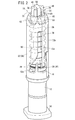
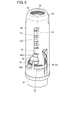
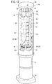
- FIG. 1 is an overall schematic cross-sectional view of a syringe assembly including a puncture needle protecting assembly according to an embodiment of the present invention. It is a principal part schematic perspective view when the assembly for a puncture needle protection which concerns on embodiment of this invention is mounted
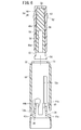
- FIG. 3 is a schematic longitudinal sectional view of a main part when the puncture needle protecting assembly of FIG. 2 is attached to a syringe.
- FIG. 3 is an exploded perspective view showing the puncture needle protecting assembly of FIG. 2 together with a syringe.
- FIG. 3 is an exploded perspective view showing a state when a needle cover is inserted into an outer cylinder in order to assemble the puncture needle protecting assembly of FIG. 2.
- FIG. 7 is a longitudinal sectional view showing a state where the needle cover is inserted into the outer cylinder following FIGS. 5 and 6.
- FIG. 8 is a longitudinal sectional view showing a state where the puncture needle protecting assembly is mounted on the syringe following FIG. 7. It is the principal part perspective view which showed the state which removed the needle
- FIG. 10 is a main part perspective view showing a state where the puncture needle is exposed from the outer cylinder, following FIG. 9;
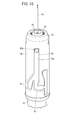
- FIG. 11 is a perspective view of a principal part showing a state where the puncture needle is housed in the outer cylinder following FIG. 10. It is a principal part schematic perspective view when the assembly for a puncture needle protection which concerns on another embodiment is mounted
- proximal end refers to an end portion on the side close to the user who operates the syringe
- leading end refers to an end portion on the side away from the user.
- FIG. 1 is an overall schematic cross-sectional view of a syringe assembly 100 according to the present embodiment.
- the syringe assembly 100 includes a prefilled syringe 102 as a syringe and a puncture needle protecting assembly 10 attached to the prefilled syringe 102.
- the prefilled syringe 102 has a hollow barrel 12 that is a body, and the barrel 12 is filled with a chemical solution 104.
- the base end side of the barrel 12 is open, and the gasket 106 is inserted into the barrel 12 from the open base end side. That is, the base end side is sealed by the gasket 106, and the chemical solution 104 is sealed in the barrel 12.
- a pusher 108 is connected to the gasket 106.
- the gasket 106 slides in the barrel 12.
- the pusher 108 is connected to the gasket 106 when the patient punctures the puncture needle 16 and administers the medicinal solution 104 to the patient.
- FIG. 2 and 3 are a main part schematic perspective view and a main part schematic longitudinal sectional view when the puncture needle protecting assembly 10 according to the present embodiment is attached to the barrel 12 of the prefilled syringe 102.
- FIG. FIG. 3 is an exploded perspective view showing the puncture needle protection assembly 10 together with a barrel 12. First, the barrel 12 will be outlined.
- the barrel 12 is a hollow body having a substantially cylindrical shape and one end opened, and the user presses a pusher 108 (not shown) on the side wall of the opened end.
- a hooking portion 14 (see FIGS. 2 and 4) to be hung is formed to protrude outward in the diameter direction.
- a needle holding portion 18 that extends along the longitudinal direction of the barrel 12 and holds the puncture needle (needle) 16 is formed on the outer wall at the other end that is closed.
- a holding hole 20 having an inner diameter corresponding to the outer diameter of the needle 16 and extending from the tip portion to the hollow inside of the barrel 12 is formed through the shaft center portion of the needle holding portion 18.
- the needle 16 is firmly fixed and held in the holding hole 20 by an appropriate fixing method such as insert molding, high-frequency or laser thermal welding, or adhesive bonding.
- the needle 16 is a hollow body in which a lead-out path 22 is formed, and the drug solution 104 accommodated in the hollow interior of the barrel 12 is discharged from the tip of the lead-out path 22 and administered to the patient.
- the puncture needle protection assembly 10 covers the needle 16 before and after the needle 16 is punctured to the patient, thereby preventing inadvertent puncture except when the drug solution 104 is administered to the patient. Is. Next, the puncture needle protecting assembly 10 will be described in detail.
- the puncture needle protecting assembly 10 includes a hollow inner cylinder 30 (inner member), an outer cylinder 32 (outer cylinder member) containing the inner cylinder 30 therein, and a puncture needle.
- a needle cover 34 that covers the needle 16 and a spring member 36 as a biasing member that biases the inner cylinder 30 toward the barrel 12 are provided.
- the inner cylinder 30 is made of resin, and has a base disc spring base 38 having a substantially disc shape and a base portion 40 projecting from the base end spring base 38 and having a substantially truncated cone shape, as shown in FIG.
- Two cam protrusions 42a and 42b are formed on the side wall of the base end spring base 38 so as to protrude outward in the diameter direction.
- the pedestal portion 40 is formed with a thin tip portion so that two arc-shaped thin portions 44a and 44b (first engaging portions) and an abutting portion 45 as an arc-shaped stepped portion are formed. Is formed.
- the needle cover 34 is connected to the inner cylinder 30 continuously.
- the needle cover 34 includes a shield 46 (a member to be punctured) through which the needle 16 is punctured and a cover 48 (rigid member) that is mounted so as to cover the shield 46 from the outside.
- the shield 46 is formed of a substantially truncated cone-shaped cylindrical body having a diameter reduced in a tapered shape from the side close to the needle 16 toward the side away from the side. Since the shield 46 is made of rubber and has a cavity 50 formed therein, it is relatively soft. Accordingly, it is easy to puncture the shield 46 with the needle 16.
- the cavity 50 has a distal end that is set in the middle of the shield 46 in the axial direction. That is, the shield 46 has a shape in which the proximal end is open and the distal end is closed, so that a hollow portion is formed on the proximal end side and a solid portion is formed on the distal end side.
- the hollow portion therein serves as a covering portion 46 a that covers the outer surface of the needle 16.
- the solid portion is a portion to be punctured 46b into which the tip of the needle 16 is punctured.
- the base end side end surface of the covering portion 46a is a close contact portion that can be in close contact with the distal end surface of the needle holding portion 18. In this way, the base end side end surface of the covering portion 46a and the distal end surface of the needle holding portion 18 are in close contact with each other, thereby sealing the covering portion 46a (cavity 50) and forming an airtight seal.
- the shield 46 is preferably made of a material that can transmit water vapor.
- Preferable examples include silicone rubber, isoprene rubber, butadiene rubber and the like.
- the cover 48 is made of a material having higher rigidity than the shield 46, for example, resin. Therefore, when the cover 48 is attached to the outside of the shield 46, the needle cover 34 is configured to exhibit sufficient rigidity. For this reason, the user can easily push the shield 46 into the outer cylinder 32 via the cover 48 or remove the shield 46 together with the cover 48 from the needle 16.
- the cover 48 has a cylindrical portion 52 at its base end.
- An annular thin portion 54 (second engaging portion) is formed in the vicinity of the opening of the cylindrical portion 52 so that a part of the inner wall thereof is cut out radially outward.
- the arcuate thin portions 44 a and 44 b of the inner cylinder 30 are inserted into the annular thin portion 54. Since the cover 48 is longer than the shield 46, the annular thin portion 54 is exposed without being covered by the shield 46.
- the proximal end side end surface of the annular thin portion 54 abuts against the abutting portion 45 of the inner cylinder 30 to press the inner cylinder 30. That is, the annular thin portion 54 also functions as a pressing portion.
- each columnar portion 56 that are separated from each other by approximately 90 ° protrude so as to extend along the central axis L of the outer cylinder 32, and each distal end portion passes through a connecting portion 58 having a cross shape. Are connected. Between the adjacent columnar portions 56, 56 is opened as a slit 60, and therefore, the side wall of the shield 46 can be visually recognized through the slit 60. That is, a part of the shield 46 is exposed by the slit 60.
- Each of the four columnar portions 56 is formed with a latching portion 62 having a tapered portion in which the protruding height gradually increases from the cylindrical portion 52 toward the connecting portion 58, in other words, toward the tip.
- four columnar portions 56 are provided, and one latching portion 62 is provided in each columnar portion 56, so that four latching portions 62 are formed in total.
- the columnar part 56 Since the columnar part 56 is narrow, the columnar part 56 is rich in flexibility and elasticity. When the columnar part 56 bends or returns to its original position by an elastic action, the latching part 62 is accompanied by the columnar part 56 and is displaced. That is, the latching part 62 can be elastically deformed.
- a support part 63 whose side wall surface is parallel to the central axis L of the outer cylinder 32 protrudes from the front end side of the latching part 62. That is, a total of four support portions 63 are also provided.
- the outer cylinder 32 is formed with a through hole 64 extending along the central axis L thereof. That is, the outer cylinder 32 is a hollow body that is open at both ends, and has a side wall 66, a tapered side wall 68 that has a tapered diameter that decreases from the side wall 66 toward the distal end side, and a diameter from the edge of the tapered side wall 68. And a stopper wall 70 (stepped portion) slightly projecting inward in the direction.
- the outer diameter of the side wall 66 is set to be slightly larger than the outer diameter of the barrel 12, as shown in FIG. Accordingly, the barrel 12 is covered by one end of the side wall 66.
- a pair of guide paths 72 a and 72 b are formed along the longitudinal direction of the side wall 66 from the substantially middle part in the longitudinal direction of the side wall 66 to the front end side.
- the guide paths 72 a and 72 b penetrate from the inner wall to the outer wall of the outer cylinder 32.
- the guide paths 72a and 72b are 180 degrees apart from each other and are rotationally symmetrical.
- cam projections 42a and 42b of the inner cylinder 30 are movably engaged with the guide paths 72a and 72b, respectively.
- the guide paths 72a and 72b are a series of long holes that branch into a bifurcated shape on the proximal end side, and that merge at the distal end side and extend linearly.
- the guide paths 72a and 72b include a first path 74, a second path 76, and a third path 78 that intersect at an intersection.
- the first path 74 in this extends linearly from the base end toward the tip, and then inclines in the circumferential direction and the tip direction toward the intersection.
- the proximal end side of the first path 74 is a pre-puncture position (initial position) where the cam protrusions 42a and 42b are positioned before the needle 16 is punctured.
- the second path 76 is a through path extending linearly from the intersection toward the tip.
- the distal end of the second path 76 is a puncturing position (base end position) at which the cam protrusions 42a and 42b move when the needle 16 is punctured.
- the third path 78 is a through path extending linearly from the intersection in the proximal direction.
- the proximal end side of the third path 78 is a post-puncture position (lock position) where the protrusion moves after the needle 16 is punctured.
- the first path 74 and the third path 78 intersect at a predetermined angle (for example, 45 ° or less).
- the tip of the barrel 12 the inner cylinder 30, the needle cover 34 and the spring member 36 are accommodated.
- the proximal end of the spring member 36 is seated on the distal end surface of the proximal end spring pedestal 38 of the inner cylinder 30, and the distal end is seated on the distal end pedestal portion which is the proximal end of the stopper wall 70 of the outer cylinder 32.
- the spring member 36 urges the inner cylinder 30 toward the barrel 12, and the latching portion 62 of the needle cover 34 (cover 48) is latched on the stopper wall 70 of the outer cylinder 32. 30 and the needle cover 34 are prevented from coming off from the outer cylinder 32.
- the stopper wall 70 is set to be sufficiently thin, and thus is highly flexible. That is, the stopper wall 70 can also be elastically deformed. Further, the side wall surface of the support portion 63 contacts the inner wall surface of the stopper wall 70.
- the spring member 36 In the spring member 36, most of the pedestal portion 40 of the inner cylinder 30 and the needle cover 34 are inserted.
- the inner diameter of the spring member 36 is set to be larger than the outer diameter of the portion of the cover 48 where the latching portion 62 is provided. Therefore, the spring member 36 does not come into contact with the cover 48 or the needle cover 34, the tip of the spring member 36 is positioned to surround the latching portion 62 from the outside, and is seated on the tip pedestal portion of the stopper wall 70. To do.
- a protective cylinder (not shown) may be further attached to the outer cylinder 32. In this case, it is only necessary to provide the protective cylinder and the outer cylinder 32 with engaging portions, and to engage the engaging portions with each other to hold the protective cylinder on the outer cylinder 32.
- the puncture needle protecting assembly 10 configured as described above can be assembled as follows. Note that the spring member 36 is not shown in FIGS. 6 to 8 in order to make the inside of the outer cylinder 32 visible easily.
- the spring member 36 is inserted into the outer cylinder 32, and the proximal end is seated on the distal end surface of the proximal spring base 38, while the distal end is seated on the proximal end of the stopper wall 70 of the outer cylinder 32.
- the inner cylinder 30 is inserted into the outer cylinder 32, and the cam protrusions 42a and 42b of the inner cylinder 30 are positioned at the base ends of the first paths 74 of the guide paths 72a and 72b.
- the needle cover 34 is obtained by attaching the cover 48 to the outside of the shield 46. At this time, the shield 46 is pushed into the cover 48 until the tip end face is blocked by the connecting portion 58. As described above, the cover 48 is longer than the shield 46. Therefore, the inside of the cylindrical portion 52 of the cover 48 is hollow.
- the needle cover 34 is inserted into the outer cylinder 32 so as to pass the needle cover 34 from the cylindrical portion 52 of the cover 48 through the tip opening of the outer cylinder 32. Since the spring member 36 has a larger diameter than the cover 48, the spring member 36 does not interfere with the needle cover 34 at this time. Since the cover 48 has a certain degree of rigidity, the soft shield 46 can be easily inserted into the outer cylinder 32 by pressing the connecting portion 58, for example.
- the inclined surface of the latching portion 62 contacts the inner wall surface of the stopper wall 70.
- the columnar part 56 provided with the latching part 62 and the stopper wall 70 exhibit sufficient flexibility.
- the latching portion 62 has a tapered shape such that the protruding height increases toward the tip. For this reason, when the needle cover 34 in a state where the inclined surface of the latching portion 62 is in contact with the inner peripheral surface of the stopper wall 70 is further pushed by pressing the connecting portion 58, the latching portion 62 is stopped. Is pressed inward in the diameter direction.
- the columnar portion 56 bends inward in the diametrical direction, and the latching portion 62 is displaced inward in the diametrical direction along with the deflecting columnar portion 56. Since the shield 46 is soft, it is deformed according to the deflection of the columnar portion 56.
- the insertion of the needle cover 34 into the outer cylinder 32 is not hindered even though the cover 48 is provided with the latch portion 62. That is, the needle cover 34 is smoothly inserted into the outer cylinder 32, and finally the arc-shaped thin portions 44 a and 44 b enter the inside of the annular thin portion 54 of the cover 48. As a result, the annular thin portion 54 is engaged with the arcuate thin portions 44 a and 44 b, and the needle cover 34 is connected to the inner cylinder 30.
- the latching portion 62 passes through the stopper wall 70 and is inserted into the outer cylinder 32, the latching portion 62 is released from the pressing force. Accordingly, the columnar portion 56 returns to its original shape due to the elastic action, and accordingly, the latching portion 62 is displaced outward in the diameter direction and returns to its original position. At this time, as shown in FIGS. 2 and 3, the flat front end surface of the latching portion 62 is latched on the ceiling surface (inner wall) of the stopper wall 70. By this latching, the needle cover 34 is prevented from coming off from the outer cylinder 32.
- the latching part 62 is provided in the middle of the columnar part 56, the upper side of the latching part 62 is exposed from the outer cylinder 32, and the side wall surface of the support part 63 abuts against the inner wall surface of the stopper wall 70. .
- a protective cylinder is attached to the outer cylinder 32 as necessary.
- the puncture needle protection assembly 10 is obtained.
- the puncture needle protection assembly 10 can be assembled alone. That is, it is not necessary to prepare the barrel 12 when assembling the puncture needle protection assembly 10. For this reason, for example, after assembling the puncture needle protecting assembly 10, it is possible to distribute it separately from the barrel 12 (or syringe). In addition, since the latching
- the equipment for assembling the puncture needle protection assembly 10 to the barrel 12 is also unnecessary. Therefore, the capital investment can be reduced.
- the puncture needle protection assembly 10 is attached to the tip of the barrel 12, as shown in FIG.
- the needle holding portion 18 is passed through the inner cylinder 30 and further enters the cylindrical portion 52 of the cover 48, and the distal end surface thereof abuts on the proximal end surface of the shield 46.
- the tip of the needle 16 passes through the cavity 50 of the shield 46 and punctures the puncture portion 46b of the shield 46.
- the shaft centers of the needle cover 34 and the inner cylinder 30 substantially coincide with each other and four latching portions 62 are provided, when the puncture needle protection assembly 10 is attached to the needle 16 and the barrel 12, Inclination of the needle cover 34 with respect to the inner cylinder 30 is avoided. Accordingly, the puncture needle 16 is prevented from being punctured by the shield 46 in an inclined posture or protruding from the needle cover 34.
- the chemical liquid 104 is filled in the barrel 12, and the barrel 12 is sealed with a gasket 106.
- the syringe assembly 100 in which the puncture needle protection assembly 10 is mounted on the prefilled syringe 102 in which the drug solution 104 is sealed in the barrel 12 is obtained.
- the syringe assembly 100 is housed in an autoclave and sterilized.
- water vapor is introduced into the autoclave.
- the water vapor sterilizes the prefilled syringe 102, passes through the opening at the front end of the outer cylinder 32, enters the outer cylinder 32, and contacts the needle cover 34.
- a slit 60 is formed between the columnar portions 56 in the cover 48 constituting the needle cover 34. For this reason, it is easy for water vapor to contact the shield 46 exposed from the slit 60.
- the shield 46 is made of rubber (for example, silicone rubber or isoprene rubber) having excellent water vapor permeability. For this reason, the water vapor in contact with the shield 46 penetrates into the shield 46 and easily reaches the inside of the covering portion 46a and the puncture portion 46b. The water vapor that has reached the portion to be punctured 46 b further enters the lead-out path 22 through the opening of the lead-out path 22. Since the outlet path 22 communicates with the inside of the barrel 12, the water vapor passes through the outlet path 22 and enters the barrel 12. As described above, the sterilization process is performed inside the needle 16.
- rubber for example, silicone rubber or isoprene rubber
- the slit 60 is formed in the cover 48 that covers the shield 46, and the shield 46 is exposed from the slit 60.
- the shield 46 can be permeated to sterilize the inside and outside of the needle 16.
- the barrel 12 may be sterilized, and then the barrel 12 may be filled with the chemical solution 104 and the barrel 12 may be sealed with the gasket 106. Even in this case, the inside and outside of the needle 16 can be sterilized for the same reason as described above.
- the user When administering the drug solution 104 to the patient, the user (which may be the patient himself) first connects the pusher 108 to the gasket 106 to obtain the state shown in FIG.
- the syringe assembly 100 may be provided to the user in a state where the pusher 108 is connected to the gasket 106 in advance as shown in FIG.
- the connecting portion 58 of the cover 48 is gripped and the needle cover 34 is pulled up.
- the latching portion 62 is pressed by the stopper wall 70 and slightly bent downward.
- the latching portion 62 is released from the stopper wall 70, so that the needle cover 34 can be easily detached from the outer cylinder 32 to be in the state shown in FIG.
- the needle 16 is relatively pulled out from the portion to be punctured 46b of the shield 46 during the separation.
- the inner cylinder 30 and the outer cylinder 32 are not displaced because the inner cylinder 30 is pressed toward the barrel 12 by the urging of the spring member 36.
- the outer cylinder 32 is sufficiently longer than the needle 16, the state where the needle 16 is surrounded by the outer cylinder 32 up to the tip is maintained. This prevents the needle 16 from being inadvertently punctured by a user or the like. Of course, the needle 16 is also prevented from coming into contact with any object, so that the hygiene of the needle 16 is maintained.
- the cam protrusions 42a and 42b are kept in the state of being arranged at the pre-puncture position (initial position).
- the user brings the tip of the outer cylinder 32 into contact with the puncture site (arm or the like) of the patient for easy positioning, and further gradually advances the barrel 12 relative to the outer cylinder 32.
- the needle 16 held by the needle holding portion 18 is exposed from the distal end opening of the outer cylinder 32.
- the inner cylinder 30 through which the needle holding portion 18 is passed also moves forward together with the barrel 12.
- the cam protrusions 42 a and 42 b of the inner cylinder 30 move from the proximal end (pre-puncture position) of the first path 74 toward the distal end side along the first path 74.
- the inner cylinder 30 rotates in the circumferential direction along the side wall of the needle holding portion 18 according to the inclination of the first path 74.
- the spring member 36 is pressed and contracted by the inner cylinder 30 that relatively moves forward.
- the cam protrusions 42a and 42b advance into the second path 76 from the intersection with the relative advance of the barrel 12, and as shown in FIG.
- the cylinder 32 moves to the proximal end position relatively moved to the proximal end side.
- most of the needle 16 is exposed from the tip of the outer cylinder 32 and is punctured into the patient's body.
- the outer cylinder 32 After administration of the drug solution 104, the outer cylinder 32 is pulled away from the patient together with the syringe. At this time, the spring member 36 extends and urges the inner cylinder 30 toward the barrel 12 side. As a result, the barrel 12 moves backward relative to the outer cylinder 32. In other words, the outer cylinder 32 moves forward relative to the barrel 12. At this time, the cam protrusions 42a and 42b linearly move in the proximal direction along the second path 76 from the distal end (puncture position) of the second path 76, and as shown in FIG. Enter the third road 78 through the intersection.
- the relative advance of the outer cylinder 32 ends when the spring member 36 elastically returns to its original shape and the cam protrusions 42a and 42b move to the post-puncture position (lock position) that is the base end of the third path 78. This is because, at this stage, the cam protrusions 42a and 42b come into contact with the base end edge portion of the third path 78, so that the outer cylinder 32 is blocked and no further relative advancement is possible.
- the base end edge (position before puncture) of the first path 74 and the base end edge (position after puncture) of the third path 78 are provided at substantially the same height from the base end of the outer cylinder 32 as a starting point. Yes. For this reason, when the cam protrusions 42 a and 42 b come into contact with the proximal end edge portion of the third path 78, the needle 16 is re-enclosed to the distal end by the outer cylinder 32. That is, the needle 16 is prevented from being exposed from the outer cylinder 32 even after puncturing. For this reason, careless puncture can be avoided even after administration of the drug solution 104 to the patient.
- the present invention is not particularly limited to the above-described embodiment, and various modifications can be made without departing from the gist of the present invention.
- a flange portion 90 as shown in FIG. 12 may be provided in a portion (tip portion) exposed from the outer cylinder 32 in the cover 48.
- the flange portion 90 protrudes in a direction orthogonal to the longitudinal direction of the needle cover 34.
- the flange portion 90 When the user pushes in the needle cover 34 when inserting the needle cover 34 into the outer cylinder 32, or when pulling out the needle cover 34 from the outer cylinder 32 in order to puncture the patient 16 with the patient, the flange portion 90 may be gripped. Thereby, pushing and pulling out proceed more smoothly.
- the needle cover 34 is configured by attaching the cover 48 to the shield 46.
- the needle cover may be configured only by the shield.
- the latching portion 62 may be provided on the side wall of the shield.
- the syringe is not limited to the prefilled syringe 102, and may be filled with the chemical solution 104 after providing the product.
Abstract
Priority Applications (4)
| Application Number | Priority Date | Filing Date | Title |
|---|---|---|---|
| JP2017509851A JPWO2016158627A1 (ja) | 2015-03-30 | 2016-03-23 | 穿刺針保護用組立体、注射器組立体及びその製造方法 |
| AU2016240594A AU2016240594B2 (en) | 2015-03-30 | 2016-03-23 | Assembly for protecting puncture needle, syringe assembly, and method for manufacturing same |
| EP16772508.4A EP3278830B1 (fr) | 2015-03-30 | 2016-03-23 | Ensemble de protection d'aiguille de ponction, ensemble de seringue et son procédé de fabrication |
| US15/719,688 US20180021524A1 (en) | 2015-03-30 | 2017-09-29 | Puncture needle protection assembly, syringe assembly, and manufacturing method thereof |
Applications Claiming Priority (2)
| Application Number | Priority Date | Filing Date | Title |
|---|---|---|---|
| JP2015068169 | 2015-03-30 | ||
| JP2015-068169 | 2015-03-30 |
Related Child Applications (1)
| Application Number | Title | Priority Date | Filing Date |
|---|---|---|---|
| US15/719,688 Continuation US20180021524A1 (en) | 2015-03-30 | 2017-09-29 | Puncture needle protection assembly, syringe assembly, and manufacturing method thereof |
Publications (1)
| Publication Number | Publication Date |
|---|---|
| WO2016158627A1 true WO2016158627A1 (fr) | 2016-10-06 |
Family
ID=57006047
Family Applications (1)
| Application Number | Title | Priority Date | Filing Date |
|---|---|---|---|
| PCT/JP2016/059274 WO2016158627A1 (fr) | 2015-03-30 | 2016-03-23 | Ensemble de protection d'aiguille de ponction, ensemble de seringue et son procédé de fabrication |
Country Status (5)
| Country | Link |
|---|---|
| US (1) | US20180021524A1 (fr) |
| EP (1) | EP3278830B1 (fr) |
| JP (1) | JPWO2016158627A1 (fr) |
| AU (1) | AU2016240594B2 (fr) |
| WO (1) | WO2016158627A1 (fr) |
Cited By (4)
| Publication number | Priority date | Publication date | Assignee | Title |
|---|---|---|---|---|
| WO2018167262A1 (fr) | 2017-03-17 | 2018-09-20 | Biocorp Production | Dispositif de protection d'aiguille pour une seringue pré-remplie à aiguille collée et seringue comprenant un tel dispositif |
| WO2019033092A1 (fr) * | 2017-08-11 | 2019-02-14 | West Pharmaceutical Services, Inc. | Système de sécurité passive d'aiguille de seringue intégré à ressort de compression soumis à un couple et collier à plusieurs parties |
| KR102379466B1 (ko) * | 2022-01-17 | 2022-03-28 | 장보경 | 필러 시술용 주사기 |
| CN115038482A (zh) * | 2019-12-10 | 2022-09-09 | 尼普洛株式会社 | 带安全机构的注射器 |
Families Citing this family (3)
| Publication number | Priority date | Publication date | Assignee | Title |
|---|---|---|---|---|
| WO2019061420A1 (fr) * | 2017-09-30 | 2019-04-04 | 群康生技股份有限公司 | Aiguille de sécurité et dispositif à aiguille de sécurité |
| EP3881881A1 (fr) | 2020-03-16 | 2021-09-22 | Gerresheimer Regensburg GmbH | Fonction supplémentaire d'un dispositif de sécurité pour seringues |
| EP3978051A1 (fr) * | 2020-10-02 | 2022-04-06 | Becton, Dickinson and Company | Seringue de sécurité |
Citations (6)
| Publication number | Priority date | Publication date | Assignee | Title |
|---|---|---|---|---|
| US4894055A (en) * | 1988-12-28 | 1990-01-16 | Sudnak Paul J | Needle guard assembly for use with hypodermic syringes and the like |
| US6719732B2 (en) * | 2000-11-17 | 2004-04-13 | Rumpler Technologies | Protection device for syringe needle |
| US20140257200A1 (en) * | 2013-03-11 | 2014-09-11 | Judith Auerbach | Safety system for a needle retaining device |
| JP2014534033A (ja) * | 2011-11-07 | 2014-12-18 | セーフティ シリンジズ, インコーポレイテッド | 接触トリガ解放式針ガード |
| US20150018773A1 (en) * | 2012-03-07 | 2015-01-15 | West Pharmaceutical Services, Inc. | Low radial profile needle safety device |
| WO2015022787A1 (fr) * | 2013-08-14 | 2015-02-19 | テルモ株式会社 | Seringue |
Family Cites Families (4)
| Publication number | Priority date | Publication date | Assignee | Title |
|---|---|---|---|---|
| US4966592A (en) * | 1989-05-05 | 1990-10-30 | Burns Cameron A | Protective sleeve for hypodermic needle |
| GB201006789D0 (en) * | 2010-04-23 | 2010-06-09 | Liversidge Barry P | Safety needle device |
| US9278179B2 (en) * | 2012-06-20 | 2016-03-08 | Safety Syringes, Inc. | Contact trigger release needle guard with elastic spring |
| FR3002741B1 (fr) * | 2013-03-01 | 2016-01-08 | Transformation Des Elastomeres A Usages Medicaux Et Ind Soc D | Dispositif de protection d'aiguille. |
-
2016
- 2016-03-23 JP JP2017509851A patent/JPWO2016158627A1/ja active Pending
- 2016-03-23 EP EP16772508.4A patent/EP3278830B1/fr active Active
- 2016-03-23 AU AU2016240594A patent/AU2016240594B2/en active Active
- 2016-03-23 WO PCT/JP2016/059274 patent/WO2016158627A1/fr unknown
-
2017
- 2017-09-29 US US15/719,688 patent/US20180021524A1/en not_active Abandoned
Patent Citations (6)
| Publication number | Priority date | Publication date | Assignee | Title |
|---|---|---|---|---|
| US4894055A (en) * | 1988-12-28 | 1990-01-16 | Sudnak Paul J | Needle guard assembly for use with hypodermic syringes and the like |
| US6719732B2 (en) * | 2000-11-17 | 2004-04-13 | Rumpler Technologies | Protection device for syringe needle |
| JP2014534033A (ja) * | 2011-11-07 | 2014-12-18 | セーフティ シリンジズ, インコーポレイテッド | 接触トリガ解放式針ガード |
| US20150018773A1 (en) * | 2012-03-07 | 2015-01-15 | West Pharmaceutical Services, Inc. | Low radial profile needle safety device |
| US20140257200A1 (en) * | 2013-03-11 | 2014-09-11 | Judith Auerbach | Safety system for a needle retaining device |
| WO2015022787A1 (fr) * | 2013-08-14 | 2015-02-19 | テルモ株式会社 | Seringue |
Non-Patent Citations (1)
| Title |
|---|
| See also references of EP3278830A4 * |
Cited By (20)
| Publication number | Priority date | Publication date | Assignee | Title |
|---|---|---|---|---|
| JP7030835B2 (ja) | 2017-03-17 | 2022-03-07 | バイオコープ・プロダクション | ステイクドニードルを備えたプレフィルドシリンジのための注射針保護装置、およびこのような装置を備える注射器 |
| FR3063909A1 (fr) * | 2017-03-17 | 2018-09-21 | Biocorp Production | Dispositif de protection d'aiguille pour une seringue pre-remplie a aiguille collee et seringue comprenant un tel dispositif |
| RU2760622C2 (ru) * | 2017-03-17 | 2021-11-29 | Биокорп Продюксьон | Устройство защиты иглы для предварительно заполненного шприца со вставленной иглой и шприц, содержащий такое устройство |
| AU2018235088B2 (en) * | 2017-03-17 | 2023-06-08 | Biocorp Production | Needle protection device for a pre-filled syringe with staked needle, and syringe comprising such a device |
| CN110325236A (zh) * | 2017-03-17 | 2019-10-11 | 生物产品公司 | 用于具有桩撑针头的预填充式注射器的针头保护设备和包括此设备的注射器 |
| JP2020509883A (ja) * | 2017-03-17 | 2020-04-02 | バイオコープ・プロダクション | ステイクドニードルを備えたプレフィルドシリンジのための注射針保護装置、およびこのような装置を備える注射器 |
| US11439771B2 (en) | 2017-03-17 | 2022-09-13 | Biocorp Production | Needle protection device for a pre-filled syringe with staked needle, and syringe comprising such a device |
| WO2018167262A1 (fr) | 2017-03-17 | 2018-09-20 | Biocorp Production | Dispositif de protection d'aiguille pour une seringue pré-remplie à aiguille collée et seringue comprenant un tel dispositif |
| US11672921B2 (en) | 2017-08-11 | 2023-06-13 | West Pharmaceutical Services, Inc. | Expandable and automatically retractable collar and method of use thereof |
| JP2020526358A (ja) * | 2017-08-11 | 2020-08-31 | ウエスト ファーマスーティカル サービシーズ インコーポレイテッド | 捻られた圧縮ばねと複数の部分を含む環状部材とが一体化された受動式注射針安全システム |
| CN111201055B (zh) * | 2017-08-11 | 2022-03-11 | 西医药服务有限公司 | 注射器针头安全系统及其组装方法 |
| CN111201055A (zh) * | 2017-08-11 | 2020-05-26 | 西医药服务有限公司 | 具有扭转压缩弹簧和多部件套环的集成式被动注射器针头安全系统 |
| US11446448B2 (en) | 2017-08-11 | 2022-09-20 | West Pharmaceutical Services, Inc. | Needle safety system |
| WO2019033100A1 (fr) * | 2017-08-11 | 2019-02-14 | West Pharmaceutical Services, Inc. | Système de sécurité d'aiguille |
| WO2019033092A1 (fr) * | 2017-08-11 | 2019-02-14 | West Pharmaceutical Services, Inc. | Système de sécurité passive d'aiguille de seringue intégré à ressort de compression soumis à un couple et collier à plusieurs parties |
| EP4309710A3 (fr) * | 2017-08-11 | 2024-04-10 | West Pharmaceutical Services, Inc. | Système de sécurité d'aiguille |
| US10888670B2 (en) | 2017-08-11 | 2021-01-12 | West Pharmaceutical Services, Inc. | Integrated passive syringe needle safety system with torqued compression spring and multi-part collar |
| CN115038482B (zh) * | 2019-12-10 | 2024-04-30 | 尼普洛株式会社 | 带安全机构的注射器 |
| CN115038482A (zh) * | 2019-12-10 | 2022-09-09 | 尼普洛株式会社 | 带安全机构的注射器 |
| KR102379466B1 (ko) * | 2022-01-17 | 2022-03-28 | 장보경 | 필러 시술용 주사기 |
Also Published As
| Publication number | Publication date |
|---|---|
| AU2016240594A1 (en) | 2017-10-12 |
| JPWO2016158627A1 (ja) | 2018-01-25 |
| EP3278830A4 (fr) | 2018-10-31 |
| AU2016240594B2 (en) | 2018-09-13 |
| EP3278830B1 (fr) | 2020-07-15 |
| EP3278830A1 (fr) | 2018-02-07 |
| US20180021524A1 (en) | 2018-01-25 |
Similar Documents
| Publication | Publication Date | Title |
|---|---|---|
| WO2016158627A1 (fr) | Ensemble de protection d'aiguille de ponction, ensemble de seringue et son procédé de fabrication | |
| AU2020220127B2 (en) | Aseptic piercing system and method | |
| US20050020985A1 (en) | Syringe with integral safety system | |
| WO2012137803A1 (fr) | Instrument de perfusion de liquide | |
| JP5591221B2 (ja) | 穿刺具組立体および薬液注入器具 | |
| WO2017073658A1 (fr) | Ensemble d'élément de préhension et de seringue | |
| JP6046721B2 (ja) | 液体投与具 | |
| JP6914913B2 (ja) | 薬液投与器具、薬液投与器具の使用方法及び薬液投与器具の製造方法 | |
| JP5578488B2 (ja) | 留置針組立体 | |
| WO2016088424A1 (fr) | Ensemble cathéter et son procédé de fabrication | |
| CN111670059A (zh) | 预填充式注射器和对预填充式注射器进行灭菌的方法 | |
| WO2023176274A1 (fr) | Dispositif d'administration de solution médicamenteuse | |
| WO2023176276A1 (fr) | Système d'administration de médicament liquide | |
| WO2023176275A1 (fr) | Dispositif d'administration de solution médicamenteuse | |
| WO2023176273A1 (fr) | Dispositif d'administration de solution de médicament | |
| WO2020256071A1 (fr) | Ensemble aiguille à demeure | |
| JP2023133658A (ja) | 薬液投与装置 | |
| JP2023133661A (ja) | 薬液投与装置 | |
| WO2017170502A1 (fr) | Seringue | |
| JP2023133659A (ja) | 薬液投与装置 | |
| JPWO2007020998A1 (ja) | セーフティプレフィルドシリンジ |
Legal Events
| Date | Code | Title | Description |
|---|---|---|---|
| 121 | Ep: the epo has been informed by wipo that ep was designated in this application |
Ref document number: 16772508 Country of ref document: EP Kind code of ref document: A1 |
|
| ENP | Entry into the national phase |
Ref document number: 2017509851 Country of ref document: JP Kind code of ref document: A |
|
| NENP | Non-entry into the national phase |
Ref country code: DE |
|
| ENP | Entry into the national phase |
Ref document number: 2016240594 Country of ref document: AU Date of ref document: 20160323 Kind code of ref document: A |