WO2016158451A1 - 結び目形成装置 - Google Patents
結び目形成装置 Download PDFInfo
- Publication number
- WO2016158451A1 WO2016158451A1 PCT/JP2016/058486 JP2016058486W WO2016158451A1 WO 2016158451 A1 WO2016158451 A1 WO 2016158451A1 JP 2016058486 W JP2016058486 W JP 2016058486W WO 2016158451 A1 WO2016158451 A1 WO 2016158451A1
- Authority
- WO
- WIPO (PCT)
- Prior art keywords
- arm mechanism
- arm
- holding member
- needle
- knot
- Prior art date
- Legal status (The legal status is an assumption and is not a legal conclusion. Google has not performed a legal analysis and makes no representation as to the accuracy of the status listed.)
- Ceased
Links
Images


Classifications
-
- A—HUMAN NECESSITIES
- A61—MEDICAL OR VETERINARY SCIENCE; HYGIENE
- A61B—DIAGNOSIS; SURGERY; IDENTIFICATION
- A61B17/00—Surgical instruments, devices or methods
- A61B17/04—Surgical instruments, devices or methods for suturing wounds; Holders or packages for needles or suture materials
- A61B17/06—Needles ; Sutures; Needle-suture combinations; Holders or packages for needles or suture materials
- A61B17/062—Needle manipulators
Definitions
- the present invention relates to a knot forming apparatus of a type that forms a knot by delivering an end of a body to be ligated, for example, a thread-like member.
- Patent Document 1 As a technique for forming a loop on a body to be ligated, for example, a thread-like member, and fixing the body to be ligated, the thread-like member is wound using a thread anchor described in Patent Document 1 made of metal or synthetic resin, for example.
- Patent Document 3 proposes a technique for welding filamentous members to each other by heat or ultrasonic waves.
- the thread-like member that is fixed by twisting, fitting, or welding these thread-like members has a problem in that the bonding strength and the tightening property are insufficient as compared with the thread-like member to be ligated.
- Patent Document 4 describes that a knot is formed by simply bundling two needle holders to restrain the relative positional relationship and performing the same operation as a manual operation. It is necessary to operate each of the two needle holders substantially.
- Patent Document 5 describes a suturing aid that forms a knot by performing a predetermined procedure. In this case, it is necessary to use another forceps for delivery of the thread-like member, and it has been impossible to form a knot with only the suturing aid.
- Patent Document 4 Although various devices for ligating a thread-like member have been proposed as in Patent Document 4 and Patent Document 5, all of them are auxiliary devices that support the ligation of the thread-like member performed by an operator, and a knot is a machine. However, it is not possible to realize a device that can be easily and reliably formed by a typical operation.
- the present invention has been made in the background of the above circumstances, and an object of the present invention is to provide a knot forming apparatus capable of easily and surely forming a knot by mechanical operation with a simple operation. There is.
- the gist of the present invention includes: (a) a base portion; and (b) a first arm mechanism and a second arm that are provided on the base portion and are configured to be relatively movable.
- a first arm mechanism and a second arm mechanism each of which includes an operation unit at least in part of the second arm mechanism; and (c) provided in the first arm mechanism, wherein the first position of the body to be ligated is determined.
- a first holding member that is detachably held; (d) a second holding member that is provided in the second arm mechanism and detachably holds the first position of the body to be ligated; and (e) the first arm.
- a third holding member provided in the mechanism and detachably holding the second position of the body to be ligated; and (f) a second position of the body to be ligated provided in the operable region of the second arm mechanism.
- a fourth holding member detachably holding (g) The loop of the body to be ligated is provided in at least one of the first arm mechanism and the second arm mechanism and intersects at two positions between the first position and the second position of the body to be ligated. (H) the first arm mechanism and the second arm mechanism are separated from each other, and the first position and the second position of the body to be ligated are defined by the first holding member and the fourth holding member.
- a first loop forming operation for forming a loop of the body to be ligated by the loop forming means in an held state, an arm approaching operation for causing the first arm mechanism and the second arm mechanism to approach each other, and the body to be ligated
- a first switching operation for switching the first position and the second position from the state of being held by the first holding member and the fourth holding member to the state of being held by the second holding member and the third holding member, and the body to be ligated 1st place
- the first arm separating operation for separating the first arm mechanism and the second arm mechanism from each other in a state where the second position is held by the second holding member and the third holding member.
- an operation portion provided on the base portion, wherein a position is passed through the loop to form a knot on the body to be ligated.
- the first arm mechanism and the second arm mechanism are separated from each other by the operation of the operation unit provided in the base unit, and the first position and the second position of the body to be ligated are second.
- the first arm mechanism and the second arm mechanism in a state in which the first and second positions of the body to be ligated are held by the second holding member and the third holding member.
- Away By first executing the arm spacing operation sequentially for the knot to the object to be ligated body said first position by passing the loop can be automatically formed.
- an operable operation unit is provided in at least a partial region of the first arm mechanism, and (j) the third holding member is provided in the operation unit of the first arm mechanism.
- the loop forming means operates an operation unit provided in the first arm mechanism;
- the operation unit separates the first arm mechanism and the second arm mechanism from each other;
- a second loop forming operation for forming a loop of the body to be ligated by the loop forming means in a state where the first position and the second position of the body to be ligated are held by the second holding member and the third holding member;
- the arm approaching operation for causing the first arm mechanism and the second arm mechanism to approach each other, and the state in which the first position and the second position of the ligated body are held by the second holding member and the third holding member.
- the first holding member and the fourth holding member A second switching operation for switching to the holding state; and the first arm mechanism and the second arm mechanism in a state in which the first position and the second position of the body to be ligated are held by the first holding member and the fourth holding member.
- the loop is again passed through the first position by sequentially performing a second arm separation operation for separating them from each other. For this reason, since the loop forming means is provided in both the first arm mechanism and the second arm mechanism, the first arm mechanism and the second arm mechanism are functionally symmetrical.
- a multi-stage knot can be automatically formed by a simple operation.
- the apparatus further comprises a moving member that relatively moves the loop of the body to be ligated formed by the loop forming means and the first position of the body to be ligated, and the moving member includes the body to be ligated. It moves to the direction which leaves
- the body to be ligated to form the loop is formed by moving the body to be ligated forming the loop along the first arm mechanism or the second arm mechanism in a direction away from the base portion. Can be moved in a direction to remove it from the first arm mechanism or the second arm mechanism, and the first position can be passed through the loop.
- the knot moves the first position of the body to be ligated from the position farther than the first position out of the two positions intersecting the loop to the position closer to the loop.
- the operation section forms the knot a plurality of times, and at any one of the plurality of knots, the loop forming means
- a loop that is wound around in the opposite direction around the previously formed loop and the expected passage path of the first position is formed.
- the loop forming means forms a loop wound around the planned loop of the first position and the previously formed loop in the opposite direction.
- a knot called an unresolved male knot can be automatically formed by a simple operation.
- the knot moves the first position of the body to be ligated from the position farther than the first position out of the two positions intersecting the loop to the position closer to the loop.
- the operation section forms the knot a plurality of times, and at any one of the plurality of knots, the loop forming means
- the loop formed in the same direction around the expected passage trajectory of the first position is formed with the previously formed loop.
- the loop forming means forms a loop wound around the planned passage of the first position in the same direction as the previously formed loop. It is possible to automatically form a knot called a female knot that is easy to tighten by a simple operation.
- the loop forming means forms the loop once around a rotation axis of an operating part provided in the second arm mechanism. This forms the most basic knot, which is called a single knot from a loop formed once.
- the loop forming means forms the loop twice around the rotation axis of the operating part provided in the second arm mechanism.
- a double knot which is called a double ligation from a loop formed twice, is formed next to the single ligation, which is simpler and harder to unravel than the single ligation.
- the loop forming means forms the loop twice in the first loop formation, and forms the loop once in the second loop formation.
- the size of the knot of the bottom double ligature is large, so the force applied to the ligation object is smaller than that of the single ligature, and the bottom knot is loosened while making the second knot. Hateful.
- the first arm mechanism and the second arm mechanism are relatively moved within their opening / closing surfaces, and the rotation axis of the operating portion of the second arm mechanism is the first arm mechanism. And a direction parallel to the opening / closing direction of the second arm mechanism.
- the direction of the separating operation of the members between the holding member provided in the first arm mechanism and the holding member provided in the operation part of the second arm mechanism, and the first position of the ligated body Since the passing direction with respect to the loop is the same, the first position of the body to be ligated can be passed through the loop by using the above-described separation operation, which is convenient.
- the relative movement direction of the second arm mechanism with respect to the first arm mechanism is a direction perpendicular to the rotation axis of the operable region of the second arm mechanism, and the rotation axis of the operation unit is A direction parallel to the opening / closing surface direction of the first arm mechanism and the second arm mechanism.
- the first arm mechanism and the second arm mechanism can move relative to each other within the opening and closing surfaces and rotate around the rotation axis in a direction parallel to the opening and closing surfaces and intersecting the loop.
- the first arm mechanism and the second arm mechanism are relatively moved within their open / close planes, and the rotation shaft is configured so that the rotation axis of the first arm mechanism and the second arm mechanism is the same. It is a direction orthogonal to the opening / closing surface and intersecting the longitudinal direction of the arm.
- the rotation shaft is configured so that the rotation axis of the first arm mechanism and the second arm mechanism is the same. It is a direction orthogonal to the opening / closing surface and intersecting the longitudinal direction of the arm.
- the first arm mechanism and the second arm mechanism move relative to each other in a direction intersecting a straight line connecting the connection portion with the base portion and the second holding member
- the second holding member and the fourth holding member are held via a second holder (cylindrical) that rotates with respect to the second arm mechanism about an intermediate point between the second holding member and the fourth holding member
- the operation unit rotates the second holder by an integral multiple of 360 degrees relative to the first holding member and the third holding member.
- the first arm mechanism and the second arm mechanism at the tip of the knot forming device open and close, so that a knot can be formed around the symmetrical object arranged so as to be sandwiched between the tips.
- the second holder by an integral multiple of 360 degrees, the first position and the second position of the body to be ligated can be exchanged even through a loop forming operation.
- the first holding member and the third holding member are arranged with respect to the first arm mechanism with an axis parallel to the relative movement direction of the first holding member and the third holding member as a rotation axis. It is held via a rotating first holder, and the operation section rotates the first holder and the second holder in an integral multiple of 180 degrees in opposite directions.
- the operation stroke of the drive unit can be halved.
- both relative rotations are integral multiples of 360 degrees, the first position and the second position of the body to be ligated can be exchanged between the first arm mechanism and the second arm mechanism even after the loop forming operation. .
- the second holder has a shape for guiding the body to be ligated to the fourth holding member via a position farther from the first holder along the relative movement direction. have.
- the vicinity of the second position of the body to be ligated rotates around the outer periphery of the second holder, or the side surface of the second holder (position away from the rotation axis) is ligated. Since the body can be hooked, the body to be ligated can be reliably wound around the second holder.
- the first arm mechanism and the second arm mechanism are relatively moved in a direction intersecting a direction connecting the connecting portion with the base portion and the second holding member,
- the holding member and the fourth holding member are held via a second holder (arm body) that rotates around a straight line connecting the connecting portion to the base portion and the second holding member, and the operation portion is
- the second holder is rotated by an integral multiple of 360 degrees with respect to the base portion.
- the first arm mechanism and the second arm mechanism at the tip of the knot forming device open and close, so that a knot can be formed around the symmetrical object arranged so as to be sandwiched between the tips.
- the second holding member and the fourth holding member are rotated together, the structure becomes simple.
- the second holder by an integral multiple of 360 degrees, the first position and the second position of the body to be ligated can be exchanged between the first arm mechanism and the second arm mechanism even after the loop forming operation. .
- the first arm mechanism and the second arm mechanism are configured to move relative to each other in a direction intersecting a tying direction between the connecting portion with the base portion and the second holding member.
- the holding member and the fourth holding member are held via a second holder (arm body) that rotates around a straight line connecting the connecting portion to the base portion and the second holding member, and the operation portion is The sum of the rotation angle of the first holder relative to the base portion and the rotation angle of the second holder relative to the base portion is rotated to be an integral multiple of 360 degrees.
- the first arm mechanism and the second arm mechanism at the tip of the knot forming device open and close, so that a knot can be formed around the symmetrical object arranged so as to be sandwiched between the tips.
- the relative rotation amount is the same regardless of which of the first arm mechanism side and the second arm mechanism side is rotated, the topology regarding the knot formation is the same, so the parts can be used in common. On the contrary, there is an advantage that the ligation is performed by the rotation mechanism only on the second arm mechanism side, and the operation stroke of the drive unit can be halved.
- the rotation axis of the fourth holding member is a direction orthogonal to a direction intersecting with a straight line connecting the connecting portion with the base member and the fourth holding member.
- the body to be ligated can be compactly stored along the second arm mechanism by rotating the fourth holding member.
- the first holder and the second holder (cylindrical first cap and second cap) rotate around the direction intersecting both the opening and closing direction and the longitudinal direction of the first arm mechanism and the second arm mechanism, the yarn Even if a needle or the like is attached to the end, the needle can be directed in the longitudinal direction of the first arm mechanism and the second arm mechanism. Therefore, the knot forming device can be downsized without being restricted by the length of the needle.
- the first arm mechanism and the second arm mechanism are relatively moved by a rotational motion such that the moving distance becomes larger as the position is farther from the base portion.
- the first arm mechanism and the second arm mechanism at the tip of the knot forming apparatus can be opened and closed like a forceps that opens and closes like a fan around the center, thereby simplifying the first arm mechanism and the second arm mechanism. Can be opened and closed.
- the fourth holding member Provided in the base portion, and the space between the first position and the second position of the body to be ligated is held by the fourth holding member via a side close to the base portion.
- a guide member for limiting the posture is included. Thereby, a to-be-ligated body can be reliably wound around the 2nd holder.
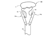
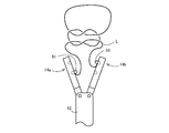
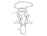
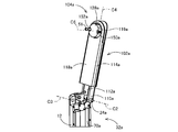
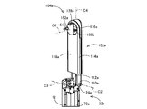
- FIG. 1 It is a front view which shows the state which the 1st arm mechanism and the 2nd arm mechanism opened of the knot formation apparatus in one Example of this invention. It is a front view which shows the state which the 1st arm mechanism and the 2nd arm mechanism of the knot formation apparatus of FIG. 1 closed. It is a perspective view which decomposes
- FIG. 1 shows the longitudinal cross-section of the knot formation apparatus of the closed state of FIG. It is a figure which shows the bottom face of the knot formation apparatus of the open state of FIG. 1, ie, the end surface of an operation member. It is a figure which shows the state which rotated the operation member provided in the knot formation apparatus of FIG. 1 45 degree
- FIG. 14 is a schematic diagram for explaining an operation performed in the order shown in FIG. 13 by a rotation operation of an operation member provided in the knot forming apparatus of FIG. 1, and shows an arm separation state in which the first arm mechanism and the second arm mechanism are opened.
- FIG. 14 is a schematic diagram for explaining an operation performed in the order shown in FIG. 13 by a rotation operation of an operation member provided in the knot forming apparatus of FIG. 1, wherein the arm main bodies provided in the first arm mechanism and the second arm mechanism are The loop formation state rotated about the axial centerline of a longitudinal direction is shown. It is the schematic diagram which looked at the thread-like member from the front-end
- FIG. 14 is a schematic diagram for explaining an operation performed in the order shown in FIG. 13 by a rotation operation of an operation member provided in the knot forming apparatus of FIG. 1, showing an arm approaching state in which the first arm mechanism and the second arm mechanism are closed. ing. It is a mimetic diagram explaining switching operation which changes a pair of needles in the state where the 1st arm mechanism and the 2nd arm mechanism were closed.
- FIG. 14 is a schematic diagram for explaining an operation performed in the order shown in FIG. 13 by a rotation operation of an operation member provided in the knot forming apparatus of FIG. 1, in which the needle is moved with the first arm mechanism and the second arm mechanism closed. The arm separation state in which the first arm mechanism and the second arm mechanism are opened after the delivery (arm approaching operation and first switching operation) is shown.
- FIG. 20 is a schematic view of the first arm mechanism after the first switching operation in FIG. 19 as seen from the tip thereof.
- FIG. 20 is a schematic diagram illustrating a state in which the thread-like member is detached from the first arm mechanism and the second arm mechanism by the thread removing operation illustrated in FIG. 19. It is a figure explaining the definition of a loop using showing the path
- FIG. 20 is a schematic view corresponding to FIG. 20 when the loop forming operation of FIG. 15 rotates the arm body twice in the single knot knot forming operation shown in FIGS. 14 to 19.
- FIG. 20 is a view corresponding to FIG. 21 when the single knot knot forming operation shown in FIGS. 14 to 19 is performed twice.
- FIG. 22 is a diagram corresponding to FIG. 21. It is a figure which shows the male knot of the thread-like member obtained by the male knot formation operation of FIG.
- FIG. 12 is a view corresponding to FIG. 11 showing an end face of another example of the operation member. It is a front view which shows the state which the 1st arm mechanism and the 2nd arm mechanism opened of the knot formation apparatus in the other Example of this invention. It is a front view which shows the state which the 1st arm mechanism and the 2nd arm mechanism of the knot formation apparatus of FIG. 32 closed. It is a perspective view which decomposes
- a 1st arm mechanism is located in a closed position and a cylindrical rotary body is pushed in It is sectional drawing which expands and shows the state performed. It is a figure which shows the back surface of a cover explaining the rotation mechanism and lock mechanism of a needle
- FIG. 39 Comprising: It is a figure which shows the state which switched the lock state of two needles mutually. It is a figure which shows the longitudinal cross-section of the knot formation apparatus of the open state of FIG. It is a figure which shows the longitudinal cross-section of the knot formation apparatus of the closed state of FIG. It is a figure which shows the bottom face of the knot formation apparatus of the open state of FIG. 32, ie, the end surface of a rotation operation member. It is a figure which shows the bottom face of the knot formation apparatus of the closed state of FIG. 32, ie, the end surface of a rotation operation member.
- FIG. 33 is a chart for explaining the relationship between the rotation operation angle of the opening / closing operation member provided in the knot forming apparatus of FIG.
- FIG. 32 shows the opening / closing operations of the first arm mechanism and the second arm mechanism operated by the rotation operation of the operation member.
- FIG. 32 shows the arm separation state in which the 1st arm mechanism and the 2nd arm mechanism were opened by rotation operation of the opening / closing operation member provided in the knot formation apparatus of FIG.
- FIG. 32 shows the schematic diagram which shows.
- FIG. 33 is a schematic diagram illustrating an arm approaching state in which the first arm mechanism and the second arm mechanism are closed by a rotation operation of an opening / closing operation member provided in the knot forming device of FIG. 32.
- FIG. 51 is a schematic diagram for explaining a switching operation state in which the pair of needles are changed in a state where the first arm mechanism and the second arm mechanism shown in FIG. 50 are closed.
- FIG. 51 shows an arm separation state in which the first arm mechanism and the second arm mechanism are opened after the needle is delivered with the first arm mechanism and the second arm mechanism closed.
- FIG. 53 is a schematic diagram showing a state where the thread-like member shown in FIG. 52 is detached from the first arm mechanism and the second arm mechanism by a thread removing operation.
- FIG. 57 is a front view showing a state in which the first arm mechanism and the second arm mechanism are closed in the knot forming apparatus of FIG. 54. It is a perspective view which decomposes
- FIG. 57 is a perspective view showing a state where the first arm mechanism of the knot forming apparatus shown in FIGS. 54 to 56 is located in an open position.
- FIG. 57 is a perspective view showing a state where the first arm mechanism of the knot forming apparatus shown in FIGS. 54 to 56 is positioned in a closed position.
- FIG. 59 is a perspective view of an essential part for explaining the needle holding mechanism provided at the distal end portion of the first arm mechanism shown in FIGS. 57 and 58 in an exploded manner. It is a perspective view explaining the principal part structure of the needle
- FIG. 55 is a bottom view of the knot forming device in the open state of FIG. 54.
- FIG. 56 is a bottom view of the knot forming device in the closed state of FIG. 55. It is a figure which shows the longitudinal cross-section of the knot formation apparatus of the open state of FIG. It is a figure which shows the longitudinal cross-section of the knot formation apparatus of the closed state of FIG. 56 is a chart for explaining the relationship between the rotation operation angle of the operation member provided in the knot forming apparatus of FIG. 54 and the opening and closing operations of the first arm mechanism and the second arm mechanism that are operated by the rotation operation of the operation member.
- FIG. 55 is a bottom view of the knot forming device in the open state of FIG. 54.
- FIG. 56 is a bottom view of the knot forming device in the closed state of FIG. 55. It is a figure which shows the longitudinal cross-section of the knot formation apparatus of the open state of FIG. It is a figure which shows the longitudinal cross-section of the knot formation apparatus of the closed state of FIG. 56 is
- FIG. 55 is a schematic diagram showing an arm separation state in which the first arm mechanism and the second arm mechanism are opened by a rotation operation of an opening / closing operation member provided in the knot forming apparatus of FIG. 54. 54.
- the first needle holding mechanism and the second needle holding mechanism provided in the first arm mechanism and the second arm mechanism, respectively, are rotated by the rotation operation of the rotation operation member provided in the knot forming device in FIG.
- It is a schematic diagram which shows the loop formation state by which a thread-like member is wound around.
- FIG. 55 is a schematic diagram showing an arm approaching state in which the first arm mechanism and the second arm mechanism are closed by a rotation operation of an opening / closing operation member provided in the knot forming device of FIG. 54.
- FIG. 71 is a schematic diagram for explaining a switching operation state in which the pair of needles are replaced with the first arm mechanism and the second arm mechanism shown in FIG. 70 closed.
- 71 is a schematic diagram showing an arm separation state in which the first arm mechanism and the second arm mechanism are opened after the needle is delivered with the first arm mechanism and the second arm mechanism closed, as shown in FIG.
- FIG. 73 is a schematic diagram showing a state where the thread-like member shown in FIG. 72 is removed from the first arm mechanism and the second arm mechanism by a thread removing operation. It is a front view which shows the state which the 1st arm mechanism and the 2nd arm mechanism opened of the knot formation apparatus in the other Example of this invention.
- FIG. 72 is a front view showing a state in which the first arm mechanism and the second arm mechanism of the knot forming device of FIG. 71 are closed.
- FIG. 75 is an exploded perspective view showing the knot forming apparatus of FIG. 74.
- FIG. 77 is a perspective view showing a state where the first arm mechanism of the knot forming apparatus shown in FIGS. 74 to 76 is positioned in the open position.
- FIG. 77 is a perspective view showing a state where the first arm mechanism of the knot forming apparatus shown in FIGS. 74 to 76 is positioned at a closed position.
- FIG. 79 is an enlarged perspective view showing the first needle disk holding mechanism provided at the tip of the first arm mechanism shown in FIGS. 77 and 78 in an exploded manner.
- FIGS. 77 and 78 are views showing a part of the first needle disk holding mechanism provided at the distal end portion of the first arm mechanism shown in FIGS. 77 and 78 from the back surface of the cover of the first arm mechanism. It shows a state in which the needle on the proximal end side is locked and unlocked.
- 77 and 78 are views showing a part of the first needle disk holding mechanism provided at the distal end portion of the first arm mechanism shown in FIGS. 77 and 78 from the back surface of the cover of the first arm mechanism. While locked, the needled disc is moved to the proximal end side.
- FIG. 79 is a perspective view showing a part of the first needle disk holding mechanism provided at the distal end portion of the first arm mechanism shown in FIGS.
- FIG. 75 is a diagram showing a bottom surface of the knot forming device in the open state of FIG. 74, that is, an end surface of the operation member.
- FIG. 76 is a diagram showing a bottom surface of the knot forming device in the closed state of FIG. 75, that is, an end surface of the operation member.
- FIG. 75 is a view showing a longitudinal section of the knot forming device in a closed state in FIG. 74;
- FIG. 76 is a view showing a longitudinal section of the knot forming device in a closed state in FIG. 75.
- FIG. 75 is a schematic diagram showing an arm separation state in which the first arm mechanism and the second arm mechanism are opened by a rotation operation of an opening / closing operation member provided in the knot forming device of FIG. 74.
- the needle-attached disk is rotated by the operation of the rotation operation member, and the outer periphery thereof.
- FIG. 75 is a schematic diagram showing an arm approaching state in which the first arm mechanism and the second arm mechanism are closed by a rotation operation of an opening / closing operation member provided in the knot forming device of FIG. 74.
- FIG. 91 is a schematic diagram for explaining a switching operation state in which the pair of needles are changed in a state where the first arm mechanism and the second arm mechanism shown in FIG. 90 are closed.
- FIG. 91 is a schematic view showing an arm separation state in which the first arm mechanism and the second arm mechanism are opened after the needle is delivered with the first arm mechanism and the second arm mechanism closed.
- FIG. 93 is a schematic diagram showing a state where the first arm mechanism and the second arm mechanism are removed from the state shown in FIG. 92 by a yarn removing operation without using a moving member. It is a schematic diagram which shows the guide member of the knot forming apparatus of the other Example of this invention.
- FIG. 32 is an example in which the dimension in the direction of the rotation axis C6 and the rotation axis C7 of the cylindrical member and the cylindrical member respectively provided at the distal ends of the first arm mechanism and the second arm mechanism of the second embodiment of FIGS. The cylindrical member provided at the tip of the second arm mechanism is shown.
- FIG. 1 to FIG. 31 are schematic views illustrating an example in which a guide member for deforming the thread-like member L extending from the first arm mechanism and the second arm mechanism downward is provided on the longitudinal member of the knot forming apparatus according to the first embodiment illustrated in FIGS. It is.
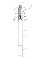
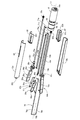
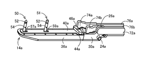
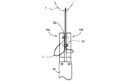
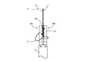
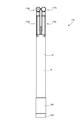
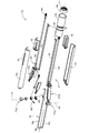
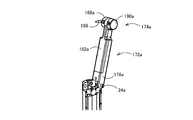
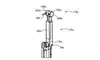
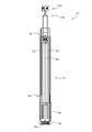
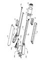
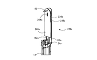
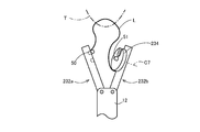
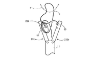
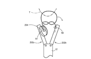
- the knot forming device 10 includes a cylindrical longitudinal base material 12 and a pair of first arm mechanism 14 a and second arm mechanism 14 b provided to be openable and closable at the distal end portion of the longitudinal base material 12.
- the base member of the longitudinal base material 12 is provided with an operation member 16 that can be rotated around the axis C1 of the longitudinal base material 12, and a rotational operation force of the operation member 16 provided in the longitudinal base material 12.
- An operating force transmission mechanism 18 is provided that transmits to the pair of first arm mechanism 14a and second arm mechanism 14b to operate the pair of first arm mechanism 14a and second arm mechanism 14b.
- the longitudinal base material 12 is comprised by the cylindrical shape by fixing a pair of partial cylindrical members 12a and 12b of a semicircular cross section in a combined state.
- the longitudinal base material 12 functions as a base portion
- the operation member 16 functions as an operation portion.
- the pair of first arm mechanism 14a and second arm mechanism 14b function as loop forming means as will be described later.
- the thread-like member L which functions as a to-be-ligated body is abbreviate
- a pair of support holes 22a and a shaft center line C2 are provided at a distal end portion of the longitudinal base material 12 at a predetermined interval on an axis C2 perpendicular to the opening and closing surfaces of the first arm mechanism 14a and the second arm mechanism 14b.
- a pair of support holes 22b are respectively formed on the axial center line C3 parallel to each other, and the first arm mechanism 14a is supported by the pair of support holes 22a so as to be rotatable around the axial center line C2, The second arm mechanism 14b is supported by the pair of support holes 22b so as to be rotatable around the axis C3.
- the first arm mechanism 14a Since the pair of the first arm mechanism 14a and the second arm mechanism 14b are configured in the same manner, the first arm mechanism 14a will be described with reference to numeral symbols with a added to the end. About 14b, the same numerical code
- the first arm mechanism 14a has a pair of support holes 22a.
- a pair of projecting shafts 24a and an opening / closing connecting arm 26a are integrally provided, and supported by the pair of support holes 22 so as to be rotatable around an axis C2 passing through the centers of the pair of support holes 22.
- the first arm mechanism 14a is connected to an arm base 30a in which a through hole 28a penetrating in a direction orthogonal to the axial center line C2 is formed and to a universal joint 32a fitted in the through hole 28a. And a shaft 34a.
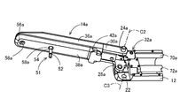
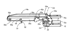
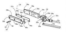
- the first arm mechanism 14a includes an arm main body 36a, a guide cover 38a, a lock plate 40a, a T-shaped bar support portion 42a, and a long lock operation bar 46a.
- the arm body 36a is provided on the arm base 30a so as to rotate about the axis C2 and to rotate about the rotation axis C4 of the through hole 28a together with the universal joint 32a.
- the guide cover 38a is fixed to the arm main body 36a so as to cover the entire facing surface on the second arm mechanism 14b side with a slight gap with respect to the facing surface.
- the lock plate 40a is accommodated so as to be movable in the longitudinal direction between the guide cover 38a and the opposing surface of the arm body 36a.
- the T-shaped bar support portion 42a is formed on the base end side of the guide cover 38a so as to be smaller than the width direction dimension of the arm body 36a and offset toward the second arm mechanism 14b.
- the lock operation bar 46a has a longitudinal dimension similar to the dimension in the width direction of the arm main body 36a. With the bar support part 42a exposed at both ends in the longitudinal direction, the lock support bar 46a is centered in the longitudinal direction inside the bar support part 42a. The portion is rotatably supported, and one end portion is engaged with the engagement recess 44a of the lock plate 40a.
- the lock operation bar 46a has a projection (not shown) at one end thereof, and the lock plate 40a with which the projection engages with the engagement recess 44a is at the distal end side position of the first arm mechanism 14a or the proximal end side. It is positioned in an inclined posture that reflects whether it is in position. For example, as shown in FIG. 6, when the lock plate 40a is located at the proximal end side position of the first arm mechanism 14a, one end side of the lock operation bar 46a is located at the proximal end side and the other end side is located at the distal end side. It is assumed to be an inclined posture. On the other hand, as shown in FIG.
- the T-shaped bar support portion 42a has a stopper function that allows both end portions of the lock operation bar 46a to abut against each other, whereby the lock plate 40a is positioned at the front end side position of the first arm mechanism 14a. And a proximal end position.
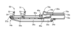
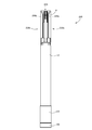
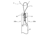
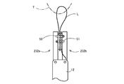
- FIGS. 2 and 5 show a state in which the first arm mechanism 14a is closed
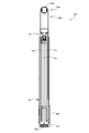
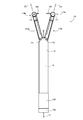
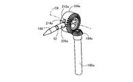
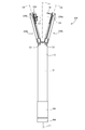
- FIG. 5 shows a pair of needles 50 and 51.
- 7 shows a state in which the needle 50 on the distal end side is released and the needle 51 on the proximal end side is locked
- FIG. 7 shows that the needle 50 on the distal end side is locked and the needle 51 on the proximal end side is released.
- annular engagement grooves 52 and 53 are formed at both ends, respectively, and a through hole 54 through which the thread-like member L functioning as a ligature is passed is formed at the center in the longitudinal direction. Has been.
- the thread-like member L is fixed to the needles 50 and 51 by so-called caulking, which is deformed by applying an external force so that the through-hole 54 is crushed while the thread-like member L is passed through the through-hole 54.
- the thread-like member L may be fixed by forming a knot larger than the through hole 54 or by adhering the thread-like member to the needles 50 and 51.
- both ends of the needle 50 are formed in a tapered shape and both ends of the needle 51 are formed flat, but the needles 50 and 51 may have the same shape.
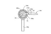
- FIG. 8 showing an enlarged view of the arm body 36a in the exploded perspective view of FIG. 3, the position of the tip of the arm body 36a and the arm at a predetermined distance from the tip of the opposing surface of the arm body 36a.
- a pair of receiving holes 56a for receiving one ends of the needles 50 and 51 are formed at two positions separated from the base 30a side, and at positions corresponding to the pair of receiving holes 56a of the guide cover 38a, A pair of through holes 58a through which the needles 50 and 51 can pass are formed.
- a pair of engagement holes 57a and 59a are formed at positions on the lock plate 40a corresponding to one and the other of the pair of receiving holes 56a and the pair of through holes 58a, respectively.
- the engagement hole 57a on the distal end side of the pair of engagement holes 57a, 59a engages with the engagement groove 52 of the needle 50 to lock the needle 50 when the lock plate 40a is at the distal end side position.
- the hole 50 is allowed to pass through. That is, a front rear circle in which a circle having a diameter larger than the diameter of the needle 50 and a rectangular notch having a width dimension larger than the groove bottom diameter of the engagement groove 52 of the needle 50 and smaller than the diameter of the needle 50 are connected. It is made into a shape.
- the engagement hole 59a on the base end side of the pair of engagement holes 57a, 59a is engaged with the engagement groove 52 of the needle 50 when the lock plate 40a is in the base end side position.
- the hole shape is formed to allow the needle 51 to pass therethrough.
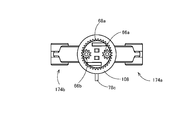
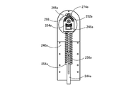
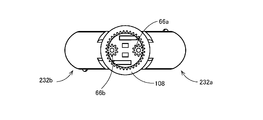
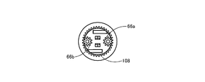
- the operation member 16 has a cylindrical shape, and on its inner peripheral surface, an arm opening / closing cam groove 60 for opening and closing the first arm mechanism 14a and the second arm mechanism 14b, and locks of the needle 50 and the needle 51 described later are provided.
- a needle lock cam groove 62 for operating the release is provided with a cylindrical groove cam 64 formed in an annular shape.
- the cylindrical groove cam 64 is formed integrally with the operation member 16, but is shown separately in FIG. 3 for the sake of illustration.
- inner peripheral teeth 68a and 68b are formed on the inner peripheral surface of the operation member 16 so that the pinions 66a and 66b for rotating the arm bodies 36a and 36b are engaged with each other. .
- the operating force transmission mechanism 18 transmits a rotational operating force for rotating the arm body 36a.
- the pinion 66a and the universal joint 32a are fixed to both ends, and the pinion 66b and the universal joint 32b for transmitting the operating force for rotating the arm body 36b are fixed to both ends.
- a second rotational operation force transmission shaft 70b is provided.
- the rotation axis C4 which is the longitudinal direction, is rotated relative to the arm base 30a clockwise, and at the same time, the arm body 36b is rotated by the clockwise rotation operation force transmitted via the second rotation operation transmission shaft 70b.
- the operating force transmission mechanism 18 includes a first opening / closing operation force transmission link 72a and a second opening / closing operation force transmission link 72b.
- the first opening / closing operation force transmission link 72a is pivotally connected to the opening / closing connection arm 26a in order to transmit an opening / closing operation force for opening / closing the first arm mechanism 14a between the open position and the closed position.
- the base end portion has a cam engaging portion 71a that protrudes at right angles to the direction and engages with the arm opening / closing cam groove 60.
- the second opening / closing operation force transmission link 72b is pivotally connected to the opening / closing connection arm 26b to transmit the opening / closing operation force for opening / closing the second arm mechanism 14b between the open position and the closed position.
- the base end portion has a cam engaging portion 71b that protrudes at right angles to the direction and engages with the arm opening / closing cam groove 60.
- FIG. 4 shows a state in which the first arm mechanism 14a is rotated to the open position.
- the first arm mechanism 14a is rotated to the open position by the movement of the first opening / closing operation force transmission link 72a.
- the first opening / closing operation force transmission link 72 a moves in accordance with the operation of the operation member 16. Specifically, when the operation member 16 is operated, the arm opening / closing cam groove 60 is rotated. When the arm opening / closing cam groove 60 rotates and the first opening / closing operation force transmission link 72a passes through a section in which the cam curve of the arm opening / closing cam groove 60 changes toward the distal end side of the longitudinal base material 12, the first opening / closing operation force is transmitted. The transmission link 72 a is moved to the distal end side of the longitudinal base material 12.
- FIG. 5 shows a state in which the first arm mechanism 14a is rotated to the open position.
- the first arm mechanism 14a is rotated to the closed position by the movement of the first opening / closing operation force transmission link 72a.
- the first opening / closing operation force transmission link 72 a moves in accordance with the operation of the operation member 16. Specifically, when the operation member 16 is operated, the arm opening / closing cam groove 60 is rotated.
- the second opening / closing operation force transmission link 72b of the second arm mechanism 14b is related to the operation of the operation member 16, and the first opening / closing operation force transmission link 72b.
- the longitudinal base 12 is moved to the distal end side and the longitudinal base 12 to the proximal end side.
- the pair of first arm mechanism 14a and second arm mechanism 14b are opened and closed.
- the operating force transmission mechanism 18 receives the one of the needles 50 and 51 between the first arm mechanism 14a and the second arm mechanism 14b and passes the other to the first arm mechanism 14a and the second arm mechanism 14b.
- a first push rod 76a and a second push rod 76b are provided to switch the pair of needles 50 and 51 from one of the engaged state and the released state to the other when they are in the closed state.
- the first push rod 76a has a T-shaped push-up portion 74a at the distal end that abuts against one end of the pair of lock operation bars 46a and 46b and rotates them, and protrudes at right angles to the longitudinal direction.
- the base end portion has a cam engagement portion 75a that engages with the lock cam groove 62.
- the second push rod 76b has a T-shaped push-up portion 74b that abuts against the other ends of the pair of lock operation bars 46a and 46b to rotate them, and protrudes at a right angle to the longitudinal direction.
- the base end portion has a cam engaging portion 75 b that engages with the needle lock cam groove 62.
- the other of the needle lock cam grooves 62 is the longitudinal base 12.
- the cam curve is formed so as to be drawn toward the base end side.
- FIG. 6 shows a state where the needle 50 is released by the lock plate 40a and the needle 51 is engaged by the lock plate 40a in the first arm mechanism 14a.
- the needle 50 is engaged by the lock plate 40b and the needle 51 is released by the lock plate 40b.
- FIG. 7 shows a state where the needle 50 is engaged by the lock plate 40a and the needle 51 is opened by the lock plate 40a in the first arm mechanism 14a.
- the needle 50 is opened by the lock plate 40b and the needle 51 is engaged by the lock plate 40b.
- the first arm mechanism 14a and the second arm mechanism 14b are in a state where the proximal end needle 51 is held by the first arm mechanism 14a and the distal end needle 50 is held by the second arm mechanism 14b. Closed.
- one end of the needle 50 on the distal end side is released from the engaged state by the lock plate 40b of the second arm mechanism 14b, and at the same time, the other end of the needle 50 is locked by the first arm mechanism 14a.
- the plate 40a is brought into the engaged state from the released state.
- one end of the proximal needle 51 is brought into the engaged state from the released state by the lock plate 40a of the first arm mechanism 14a, and at the same time from the released state to the engaged state by the lock plate 40b of the second arm mechanism 14b.
- the proximal needle 51 is held by the second arm mechanism 14b and the distal needle 50 is held by the first arm mechanism 14a. It becomes a state. That is, the distal side needle 50 and the proximal side 51 are exchanged between the first arm mechanism 14a and the second arm mechanism 14b.
- the engagement hole in the distal end side of the receiving hole 56a of the arm body 36a, the one on the distal end side in the through hole 58a of the guide cover 38a, and the engagement hole in the lock plate 40a of the first arm mechanism 14a It functions as a first holding member that holds the needle 50 on the distal end side in combination with the portion where 57a is formed.
- the front end side of the receiving hole 56b of the arm body 36b, the front end side of the through hole 58b of the guide cover 38b, and the engagement hole 57b of the lock plate 40b of the second arm mechanism 14b are provided.
- the formed portion is combined to function as a second holding member that holds the needle 50 on the distal end side.
- the base end side of the receiving hole 56a of the arm body 36a, the base end side of the through hole 58a of the guide cover 38a, and the engagement hole of the lock plate 40a of the first arm mechanism 14a functions as a third holding member that holds the needle 51 on the proximal end side in combination with the portion where 59a is formed.
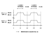
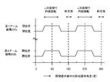
- FIG. 13 shows a lock and release operation of the needle 50 and the needle 51 by the lock plate 40a and the lock plate 40b by one rotation operation of the operation member 16 (however, the lock and release operation by the lock plate 40b is shown in FIG. Is not the same as the operation of the lock plate 40a), the rotation of the arm body 36a of the first arm mechanism 14a and the arm body 36b of the second arm mechanism 14b, and the first arm mechanism 14a and second arm mechanism 14b.
- the horizontal axis of the chart of FIG. 13 indicates an angle obtained by rotating the operation member 16 clockwise as viewed from the directions of FIGS.
- 11 and 12. 11 is about 135 degrees from the origin of the horizontal axis of the chart, and FIG. 12 is a position rotated about 45 degrees, that is, 270 degrees from FIG.
- the one rotation operation of the operation member 16 may be a manual operation or a remote operation in which the operation member 16 is rotated by a motor.
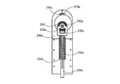
- the moving member 78 has a cylindrical longitudinal base. It is accommodated in the longitudinal base material 12 so that it can project from the front-end
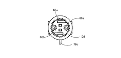
- the moving member 78 is a part that is bent in an inverted U shape as a whole from one wire, and includes a short wire portion 78b that connects the ends of a pair of long wire portions 78a parallel to each other, and one long wire portion 78a. And an operation projection 78c protruding outward from the long hole 80 formed in the partial cylindrical member 12a.
- the to-be-ligated body L is moved in the direction away from the longitudinal base material 12 along the longitudinal direction of the first arm mechanism 14a and the second arm mechanism 14b by the short line portion 78b of the moving member 78 that has been pushed out.
- the projecting operation of the moving member 78 may be manually operated on the operation projection 78c, or may be a remote operation operated using an actuator such as a pneumatic cylinder or an electric cylinder.
- a cylindrical receiving member 82 is disposed on the base end side in the longitudinal base 12.
- the receiving member 82 rotatably supports the first rotational operation force transmission shaft 70a and the second rotational operation force transmission shaft 70b. Further, the receiving member 82 supports the first opening / closing operation force transmission link 72a and the second opening / closing operation force transmission link 72b so as to be movable in the longitudinal direction, and the first opening / closing operation force transmission link 72a and the second opening / closing operation force.
- the cam engaging portion 71a and the cam engaging portion 71b provided on the base end side of the transmission link 72b are guided in the longitudinal direction using the pair of guide holes 82a.
- the receiving member 82 supports the first push rod 76a and the second push rod 76b so as to be movable in the longitudinal direction, and is provided on the base end side of the first push rod 76a and the second push rod 76b.
- the engaging portion 75a and the cam engaging portion 75b are guided in the longitudinal direction using the pair of guide holes 82b.
- the operation member 16 when the operation member 16 is rotated, as shown in FIG. 13, the first arm mechanism 14a and the second arm mechanism 14b are opened and closed, and the needle 50 and the needle 51 are locked. The release operation and the rotation operation of the arm main body 36a and the arm main body 36b are performed. Thereafter, when the thread member L is removed from the first arm mechanism 14a and the second arm mechanism 14b by the moving member 78, a loop of the thread member L in which the knot M1 is formed is automatically formed.
- the operation of the knot forming apparatus 10 of this embodiment will be specifically described below.
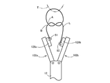
- the thread-like member L In order for the knot formed by the thread-like member L to be a knot that closes the thread-like member L surrounding the ligation symmetrical object in an annular shape, the thread-like member L, the first arm mechanism 14a, the second arm mechanism 14b, the longitudinal base The ligation symmetry object is surrounded in a closed path made of the material 12.
- An annular path combining the thread-like member L and the broken line D in FIG. 14 is a closed path referred to here.
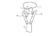
- the first arm mechanism 14a and the second arm mechanism are moved from the state in which the distal end needle 50 is locked by the lock plate 40b of the second arm mechanism 14b.
- the suture portion of the living tissue T sandwiched between the distal end portion of the first arm mechanism 14a and the distal end portion of the second arm mechanism 14b is penetrated by the needle 50 on the distal end side, and the first arm mechanism 14a If the first arm mechanism 14a and the second arm mechanism 14b are opened while the distal end side needle 50 is locked by the lock plate 40a, a part of the living tissue T becomes the thread-like member L, the first arm mechanism 14a, and the second arm mechanism 14b.
- the arm mechanism 14b and the longitudinal base 12 are surrounded by a closed path.
- the operation member 16 is at an operation position near 45 degrees.
- FIG. 14 schematically shows this state.
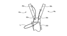
- the arm main body 36a of the first arm mechanism 14a and the arm main body 36b of the second arm mechanism 14b are connected to each other by the first arm mechanism 14a and the second arm mechanism 14b.
- a loop is formed around the arm body 36b by being rotated once in the same rotational direction around the rotation axes C4 and C5 in the longitudinal direction of the first arm mechanism 14a and the second arm mechanism 14b in parallel with the opening / closing surface.
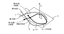
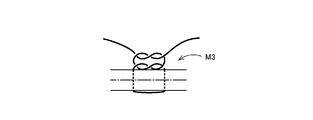
- the loop here refers to a surrounding portion when the thread-like member L surrounds a certain axis over one round and 360 degrees or more.
- the mapping of the thread-like member L self-intersects, and the axis exists in an annularly closed portion including the intersection of the mapping.
- the real part that is the origin of the annular part of the map is the loop.
- “passing” means that the loop and the end of the yarn pass relative to each other along the axis that defines the loop, and the relative positional relationship in the axial direction is switched. Since the loop is defined in relation to the axis of the loop, for example, in FIG.
- the loop of the thread-like member that appears to be a simple S shape in the front view is the direction of the rotation axis C5 as shown in FIG.
- a closed ring may occur, but if the above "pass” is made in the direction along the axis, the knot can be made to see how it looks from the other direction, and conversely the axis If the above-mentioned “passing” is not performed in the direction along the line, a knot cannot be formed even if it looks like a loop is seen from the other direction.
- the schematic diagrams of FIGS. 15, 16 and 17 show a state after a loop in the above sense is formed by the first loop forming operation.
- FIGS. 16 (a) and 16 (b) show a state in which the living tissue T is positioned in front of the figure with respect to the knot forming device 10
- FIGS. 16 (c) and 16 (d) show the living tissue T in the knot. It is the figure seen from the base end side in the direction of rotation-axis C4, C5, respectively, when it is located in the back
- a loop is formed around the arm body 36a. Due to the overall symmetry, knots are formed in the same way in the following description.
- a loop is formed around at least one of the arm bodies 36a and 36b by rotating both arm bodies 36a and 36b in the same direction.
- the loops shown in FIGS. 16B and 16D can be formed simultaneously. Subsequently, the first arm mechanism 14a and the second arm mechanism 14b are closed by a first arm approaching operation that operates the operating member 16 to around 135 degrees.
- FIG. 17 shows a state where the first arm approaching operation is completed.
- FIG. 17 shows a state before the first switching operation
- FIG. 18 shows a state after the first switching operation. 17 and 18, the state in which the needle 50 and the needle 51 are locked is indicated by hatching in the first arm mechanism 14a and the second arm mechanism 14b.
- the operation member 16 When the operation member 16 is operated to around 225 degrees, the first arm mechanism 14a and the second arm mechanism 14b are opened. 19 and 20 show the first arm separation operation.
- the thread-like member L is wound around the second arm mechanism 14b so as to form a loop R composed of the thread-like member L, and the first needle 50 and the proximal-side needle 51 of the distal end side are formed.
- the delivery between the arm mechanism 14a and the second arm mechanism 14b is completed.
- the closed path composed of the thread-like member L, the first arm mechanism 14a, the second arm mechanism 14b, and the longitudinal base material 12 is already knotted in a topological sense at this point.
- the shape before and after the deformation is said to be topologically the same.
- a discontinuous deformation such as a deformation in which the thread passes through the thread, or a deformation in which the ring is cut once and the thread is traversed and then closed again.
- Leidhoff movement the shape that can be deformed only by continuous deformation (referred to as Leidhoff movement) without topology is the same topologically.
- the topology is different between an annularly closed thread not including a knot and a closed thread including a knot.
- the knot already in topology means that the closed path composed of the thread-like member L, the first arm mechanism 14a, the second arm mechanism 14b, and the longitudinal base material 12 can be closed only by continuous deformation. This means that it can be deformed into a shape in which a knot shape exists only in the portion consisting of L.
- FIG. 21 shows a state in which the thread-like member L is detached from at least the first arm mechanism 14a of the first arm mechanism 14a and the second arm mechanism 14b after the first arm separation operation.
- the thread-like member L is disengaged from the first arm mechanism 14a and the second arm mechanism 14b when a first arm separation operation or a series of operations including a first arm separation operation and an operation of projecting the moving member 78 in the arrow direction is performed.
- the thread-like member L when the first arm separation operation and the operation of projecting the moving member 78 in the direction of the arrow are performed in the schematic diagram of FIG. 21 by continuous deformation while maintaining the same topology topology of the closed path.
- a so-called single knot knot M1 is formed only by the thread-like member L.
- the thread-like member L may be removed from at least the second arm mechanism 14b by moving the longitudinal base 12. If there is no hindrance in subsequent operations performed by the first arm mechanism 14a and the second arm mechanism 14b, the thread-like member L does not necessarily have to be removed from the first arm mechanism 14a.
- the thread-like member L is tightened to obtain the single ligature M1 shown in FIG. That is, the single ligature M1 by the thread-like member L is automatically formed by such a single ligature formation operation.
- the entity of the thread-like member L projected as the intersection of the closed paths is , A three-dimensional intersection composed of two positions of the thread-like member L, that is, a first intersection position A closer to the first position that is one end of the thread-like member L and a second intersection position B farther away. Passing the first position, which is one end portion of the thread-like member L through which the loop passes, in the direction from the second intersection position B side to the first intersection position A side, that is, in the direction of the arrow of the virtual axis K. Can make a knot. For example, referring to FIG.
- the thread-like member L is transferred by the delivery of the needle 50 and the needle 51 following the closing operation of the first arm mechanism 14a and the second arm mechanism 14b in a state where a loop is formed around the arm body 36b.
- the portion that is passed through the needle 50 that is the first position of the first position is the second of the two positions of the thread-like member L corresponding to the intersection of the loops, the second position closer to the second intersection position B that is farther from the first position. Since the loop is relatively passed to the one intersection position A side, a knot M1 is formed in the loop.
- the operation member 16 when the operation member 16 is operated up to around 135 degrees, the arm main body 36a of the first arm mechanism 14a and the arm main body 36b of the second arm mechanism 14b are rotated around the longitudinal axis thereof. It is also possible to use the operation member 16 having the inner peripheral teeth 68a and 68b having the number of teeth for performing the operation of rotating twice. Or if it is the structure which rotates the arm main body 36a and the arm main body 36b using the 2nd operation member independent of the operation member 16 used for opening and closing of the 1st arm mechanism 14a and the 2nd arm mechanism 14b. The second operating member can be rotated by an angle twice as large as when the arm main body 36a and the arm main body 36b are rotated once.
- the thread-like member L is wound twice around the second arm mechanism 14b to form a loop.
- the needle 50 and the needle 51 are delivered from this state and the moving member 78 is pushed out to remove the thread-like member L from the first arm mechanism 14a and the second arm mechanism 14b, as shown in the schematic diagram of FIG. A loop in which a so-called double knot knot M2 is formed is formed.
- the double ligation M2 of FIG. 25 is obtained by tightening the thread-like member L. That is, according to the knot forming apparatus 10 of the present embodiment, the double ligation M2 is automatically formed by such a double ligation forming operation.
- the arm main body 36a and the arm when the second single ligature is formed with respect to the rotation direction of the arm main body 36a and the arm main body 36b when the first single ligature is formed.
- a loop in which the so-called male knot M4 shown in the schematic diagram of FIG. 28 is formed is formed, and the thread-like member L is tightened to obtain the male knot M4 of FIG. It is done. That is, according to the knot forming apparatus 10 of the present embodiment, the male knot M4 is automatically formed by performing the single knot forming operation twice.
- the arm main body 36a and the arm main body 36b can be rotated in the reverse direction by reversing the rotation direction of the operation member 16.
- the single ligation M1 is formed by performing the single ligation formation operation subsequently, so that the second ligation M2 is formed in the first stage as shown in FIG.
- a surgical ligature M5 having a single ligature M1 in the second stage is formed.
- Such a surgical ligature M5 can also be automatically formed by using the knot forming device 10 of the present embodiment.
- the second arm mechanism 14 b holds the needle 50
- the first arm mechanism 14 a holds the needle 51. Therefore, the second knot can be formed by performing the replacement operation of the needles 50 and 51 again, returning the apparatus to the initial state, and performing the same operation.
- the first arm mechanism 14a is formed. Since the second arm mechanism 14b is configured to be functionally symmetrical, the second-stage knot can be formed immediately after the first-stage knot has been formed. In this case, the first arm mechanism 14a, the second arm mechanism 14b, and these components are used in reverse to the procedure for forming the first knot. In the above description of the present specification, the subscripts a and b may be replaced.
- the arm main body 36a of the first arm mechanism 14a and the arm main body 36b of the second arm mechanism 14b are rotated around the longitudinal axis in the same rotational direction.
- the arm main body 36b of the second arm mechanism 14b to which the proximal end needle 51 is fixed may be rotated once.
- the first arm mechanism 14 a and the second arm mechanism 14 b are operated by operating the operation member (operation unit) 16 provided at the base end portion of the longitudinal base material (base portion) 12.
- the operation member (operation unit) 16 provided at the base end portion of the longitudinal base material (base portion) 12.
- the first crossing position of the thread-like member L passed through the needle 50 and the second crossing position of the thread-like member L passed through the needle 51 are separated from each other.
- both ends of the thread-like member L are held at positions apart from the separate first arm mechanism 14a and second arm mechanism 14b, so that the thread-like member L is not easily entangled and tightened thereafter. And cutting becomes easy.
- the arm main bodies (operation units) 36a and 36b are provided in the first arm mechanism 14a and the second arm mechanism 14b, and the operation member (operation unit) 16 is 1 Following the first knot forming operation, the first arm mechanism 14a and the second arm mechanism 14b are separated from each other, and the first position and the second position of the thread-like member L are held by the second holding member and the third holding member.
- a second loop forming operation for forming a loop of the thread-like member L by the arm main bodies (operation units) 36a and 36b, an arm approaching operation for causing the first arm mechanism 14a and the second arm mechanism 14b to approach each other, A second state in which the first position and the second position of the thread-like member L are switched from the state of being held by the second holding member and the third holding member to the state of being held by the first holding member and the fourth holding member.
- the second arm that separates the first arm mechanism 14a and the second arm mechanism 14b from each other in a state in which the first position and the second position of the thread-like member L are held by the first holding member and the fourth holding member.
- the loop is again passed to the first position by sequentially performing the separation operation.
- the arm main bodies (loop forming means) 36a and 36b are provided in both the first arm mechanism 14a and the second arm mechanism 14b, the first arm mechanism 14a and the second arm mechanism 14b are functionally symmetrical.
- the first loop forming operation By sequentially executing the first loop forming operation, the arm approaching operation, the first switching operation, and the first arm separating operation, the second loop forming operation, the loop can be passed again to the first position of the thread-like member L to form the next second knot.
- Multi-stage knots can be formed automatically with a simple operation.
- the thread-like member L can be wound around the first arm mechanism 14a and the second arm mechanism 14b itself at the time of loop formation, a knot forming apparatus that is space efficient and compact and can be automatically ligated is provided. can get.
- both ends of the thread-like member L are held separately by the first arm mechanism and the second arm mechanism before and after the knot formation, so that the thread-like member L is not easily entangled, and subsequent tightening and cutting are easy. .
- first arm mechanism 14a and the second arm mechanism 14b at the tip of the knot forming device 10 are opened and closed, a symmetrical object sandwiched between the first arm mechanism 14a and the second arm mechanism 14b, for example, the living tissue T Knots can be formed around. Further, the first arm mechanism 14a and the second arm mechanism 14b can be operated in the first position and the second position even after the loop forming operation by the rotation of the second arm main body 36b as the second holder in accordance with the operation of the operation member 16. Can be exchanged with.
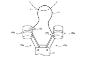
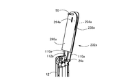
- FIG. 32 is a front view showing a state in which the first arm mechanism 102a and the second arm mechanism 102b of the knot forming apparatus 100 according to another embodiment of the present invention are open
- FIG. 33 is a first view of the knot forming apparatus 100
- 34 is a front view showing a state in which the arm mechanism 102a and the second arm mechanism 102b are closed
- FIG. 34 is an exploded perspective view showing the knot forming device 100.
- the knot forming apparatus 100 functions as an operating unit based on the rotational operation force transmitted through the first rotational operation force transmission shaft 70a and the second rotational operation force transmission shaft 70b, and the needles 50 and 51.
- a pair of first cylindrical rotating mechanism 104a and second cylindrical rotating mechanism 104b functioning as a needle locking mechanism that detachably holds the first and second cylindrical rotating mechanisms 104a and 102b are provided at the distal ends of the first arm mechanism 102a and the second arm mechanism 102b, respectively.
- the operating force transmission mechanism 18 does not include the first push rod 76a and the second push rod 76b, and a pair of opening / closing operation members that are provided at the base end portion of the longitudinal base 12 so as to be rotatable as operation members.
- 106 and the rotation operation member 108 are different from the knot forming apparatus 10 in FIG. To have.
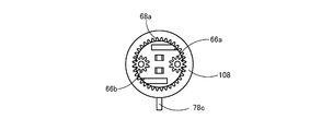
- the knot forming apparatus 100 includes a cylindrical long base 12, a pair of first arm mechanism 102 a and second arm mechanism 102 b, a pair of opening / closing operation members 106, a rotation operation member 108, and an operation force transmission mechanism 18.
- the pair of first arm mechanism 102a and second arm mechanism 102b are rotatably supported around the axial center line C2 and the axial center line C3 that are parallel to each other at the distal end portion of the longitudinal base material 12, and are provided to be openable and closable. ing.
- the pair of opening / closing operation members 106 and the rotation operation member 108 are provided so as to be rotatable around the axis C1 of the longitudinal base material 12 at the proximal end portion of the longitudinal base material 12, and are provided so as to be relatively rotatable with respect to each other. Yes.
- the operating force transmission mechanism 18 is provided in the longitudinal base material 12, and the opening / closing operation force of the opening / closing operation member 106 and the rotation operation member 108 are used as a pair of first arm mechanism 102 a and second arm mechanism 102 b, and a pair of first cylindrical rotations. This is transmitted to the mechanism 104a and the second rotation mechanism 104b.
- the pair of opening / closing operation members 106 and the rotation operation member 108 function as an operation unit.
- the first arm mechanism 102a includes an arm main body 114a, a cover 118a, a first cylindrical rotation mechanism 104a, and a rotation drive shaft 122a.
- the arm main body 114a is positioned between a pair of parallel plates 110a each having a projecting shaft 24a with the open / close connecting arm 26a fixed to one side and projecting outward, and the universal joint 32a is rotatable.
- a joint receiving member 112a formed with a through hole 28a to be received in the base end portion.
- the arm main body 114a and the cover 118a have a circular opening 116a formed at the tip, and are fixed to the arm main body 114a so as to cover the opposing surface of the arm main body 114a.
- the rotation drive shaft 122a is supported between the arm main body 114a and the cover 118a so as to be rotatable about a central axis of the through hole 28a, that is, a rotation axis C4 parallel to the longitudinal direction of the first arm mechanism 102a, and universally connected to the base end.
- the joint 32a is connected, and the pinion 120a is fixed to the tip.
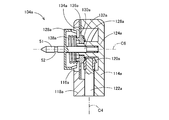
- FIG. 37 is a longitudinal sectional view illustrating the configuration of the first cylindrical rotating mechanism 104a.
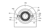
- the first cylindrical rotation mechanism 104a includes a cylindrical member 128a, a bevel gear member 132a, and a guide plate 136a.
- the cylindrical member 128a has a central shaft portion 126a fitted into a cylindrical bearing 124a projecting inwardly from the arm main body 114a, and the first arm mechanism 102a and the second arm mechanism 102b by the cylindrical bearing 124a.
- the bevel gear member 132a is rotatably supported by the outer peripheral surface of the tip end portion of the cylindrical bearing 124a and has a plate-like lock flange 130a protruding to the outer periphery.
- the guide plate 136a includes a guide plate 136a that is sandwiched between the arm main body 114a and the cover 118a and that forms an annular slot 134a between the outer peripheral edge of the lock flange 130a located on the inner side.
- the bevel gear member 132a meshes with the pinion 120a provided at the shaft end of the rotation drive shaft 122a, so that the cylindrical member 128a and the bevel gear member 132a are rotationally driven around the rotation axis C6.
- the cylindrical member 128a is urged in the protruding direction by a spring 138a inserted between the cylindrical member 128a and the bevel gear member 132a.
- a spring 138a inserted between the cylindrical member 128a and the bevel gear member 132a.
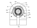
- FIG. 39 and 40 are views seen from the side of the arm main body 114a showing the state in which the needle 50 is released and the needle 51 is locked between the lock flange 130a and the guide plate 136a.
- FIG. 40 is a view of the cylindrical rotation mechanism 104a as viewed from the arm main body 114a side
- FIG. 40 is a view showing the cylindrical member 128a, the rotation drive shaft 122a, and the cover 118a from FIG. 41
- FIG. 41 is a view corresponding to FIG. 40 showing a state in which the needle 50 is locked and the needle 51 is released between the lock flange 130a and the guide plate 136a.
- FIG. 42 is a view corresponding to FIG. 39 showing a state in which the cylindrical member 128a is rotated in a state where the needle 50 is released and the needle 51 is locked between the lock flange 130a and the guide plate 136a.
- the radial dimension of the annular slot 134a formed between the outer peripheral edge of the lock flange 130a and the inner peripheral edge of the guide plate 136a is smaller than the outer diameter of the needle 50 and the needle 51, and is smaller than the groove bottom diameter of the engagement groove 52. Is also set larger. Further, at two positions on the straight line passing through the rotation axis C6 and orthogonal to the rotation axis C4 in the inner peripheral edge of the guide plate 136a, an arc shape having a curvature radius larger than the curvature radius of the outer diameter of the needle 50 and the needle 51 is formed.
- the outer arc-shaped notches 139a and 140a having the outer arc are formed at positions opposite to the rotation axis C6.
- the two outer circumferential edges of the lock flange 130a are 180 degrees apart in the circumferential direction and have a radius of curvature larger than the radius of curvature of the needles 50 and 51, and the outer arc-shaped notches 139a and 140a.
- the inner arc-shaped notches 142a and 144a that allow the needle 50 and the needle 51 to pass between the guide plate 136a and the inner peripheral edge of the guide plate 136a are smaller than the groove bottom diameter of the engagement groove 52 of the needle 50 and the needle 51.
- Inner rectangular cutouts 146a and 148a that are larger and have an interval smaller than the outer diameter of the needle 50 are formed to be connected in a semi-front and rear circular shape.
- needle receiving grooves 150a and 152a having a semicircular cross section parallel to the rotation axis C6 for receiving the needle 50 and the needle 51 are provided. Is formed.
- the needle 50 received in the needle receiving groove 150a of the cylindrical member 128a is allowed to be removed between the outer arcuate cutout 139a and the inner arcuate cutout 142a, and the cylindrical member 128a
- a state in which the needle 51 received in the needle receiving groove 152a is prevented from coming off between the outer arc-shaped notch 140a and the inner rectangular notch 148a is shown.
- the lock flange 130a and the bevel gear member 132a are rotated counterclockwise as shown in FIG. 40 from this state, the cylindrical member 128a is also rotated by being pushed by the needle 51 that is prevented from coming off, and the cylindrical member 128a.
- FIG. 41 shows this state.
- the needle 50 is allowed to slip out between the outer arcuate cutout 139a and the inner arcuate cutout 142a, and the needle 51 is removed from the outer arcuate cutout 140a and the inner rectangular cutout. Omission is prevented between the notch 148a. From this state, when the lock flange 130a and the bevel gear member 132a are rotated counterclockwise by a predetermined angle, as shown in FIG.
- the needle 50 is positioned between the outer arcuate cutout 139a and the inner rectangular cutout 146a. And the needle 51 is prevented from coming off between the outer arcuate cutout 140a and the inner arcuate cutout 144a. In other words, the locked state of the needle 50 and the needle 51 is switched depending on which direction is last rotated.
- a combination with the portion where the outer arc-shaped notch 139 a is formed functions as a first holding member that holds the needle 50.
- the combination with the portion where 139 b is formed functions as a second holding member that holds the needle 50.
- the combination with the portion where 140 a is formed functions as a third holding member that holds the needle 51.
- the combination with the portion where 140 b is formed functions as a fourth holding member that holds the needle 51.
- a cylindrical opening / closing operation member 106 provided at the proximal end portion of the longitudinal base material 12 of the knot forming device 100 of the present embodiment so as to be rotatable around its axis C1;
- a cylindrical rotation operation member 108 provided adjacent to the opening / closing operation member 106 so as to be rotatable around the axis C1 of the longitudinal base material 12 is provided so as to be operated independently of each other.
- the opening / closing member 106 is integrally provided with a cylindrical groove cam 64 in which an arm opening / closing cam groove 60 for opening / closing the first arm mechanism 102a and the second arm mechanism 102b is formed in an annular shape.
- the cylindrical groove cam 64 is formed integrally with the operation member 16, but is shown separately in FIG. 34 for convenience of illustration.
- FIGS. 45 shows a state in which the pair of first arm mechanism 102a and second arm mechanism 102b is opened
- FIG. 46 shows a state in which the first arm mechanism 102a and second arm mechanism 102b are closed.
- the operation force transmission mechanism 18 transmits a rotational operation force for rotating the first cylindrical rotation mechanism 104a. Therefore, the pinion 66a meshing with the inner peripheral teeth 68a of the rotation operation member 108 shown in FIG. 45 and the first rotation operation force transmission shaft 70a having the universal joint 32a fixed at both ends and the operation force for rotating the second rotation mechanism 104b are provided. 45, a pinion 66b meshing with the inner peripheral teeth 68a of the rotation operation member 108 shown in FIG. 45 and a second rotation operation force transmission shaft 70b fixed to both ends of the universal joint 32b are provided.
- the operating force transmission mechanism 18 is pivotally connected to the open / close connection arm 26a in order to transmit an opening / closing operation force for opening and closing the first arm mechanism 102a between the open position and the closed position.
- the first opening / closing operation force transmission link 72a having a cam engaging portion 71a protruding at a right angle with respect to the arm opening / closing cam groove 60 at the base end portion and the second arm mechanism 102b in the open position and the closed position
- a cam engaging portion 71b is connected to the opening / closing connecting arm 26b so as to be pivotable, protrudes at right angles to the longitudinal direction, and engages with the arm opening / closing cam groove 60.
- a second opening / closing operation force transmission link 72b at the base end.
- FIG. 47 shows the opening / closing operation of the first arm mechanism 102a and the second arm mechanism 102b by one rotation operation of the opening / closing operation member 106, and the first cylindrical rotation mechanism 104a and the second cylinder operation by the rotation operation member 108 in a predetermined rotation phase section. It is a chart explaining the state in which the rotation operation of the cylindrical rotation mechanism 104b and the replacement operation of the needle 50 and the needle 51 are executed in a predetermined order for knot formation.
- the horizontal axis of the chart in FIG. 47 indicates an angle obtained by rotating the opening / closing operation member 106 clockwise as viewed from the directions of FIGS. 45 and 46.
- the rotation operation member 108 When the rotation member 108 rotates the cylindrical member 128a of the first cylindrical rotation mechanism 104a and the cylindrical member 128b of the second cylindrical rotation mechanism 104b to wind the thread-like member L, the rotation operation member 108 and the first arm mechanism 102a
- the needle 50 and the needle 51 are exchanged between the first cylindrical rotating mechanism 104a and the second cylindrical rotating mechanism 104b by operating in the section where the two-arm mechanism 102b is in the open position, the first arm mechanism 102 and the first It is operated in a section where the two-arm mechanism 102b is in the closed position.
- 45 is about 135 degrees from the origin of the horizontal axis of the chart
- FIG. 46 is a position rotated about 45 degrees.
- the rotation operation of the opening / closing operation member 106 and the rotation operation member 108 may be a manual operation or a remote operation that is rotated by a motor.
- the first arm mechanism 102a and the second arm mechanism are moved from the state in which the needle 50 is locked by the second cylindrical rotation mechanism 104b of the second arm mechanism 102b. 102b is closed.
- the suture portion of the living tissue T sandwiched between the distal end portion of the first arm mechanism 102a and the distal end portion of the second arm mechanism 102b is penetrated by the needle 50.
- the rotation operation member 108 is operated, whereby the cylinder member 128a of the first cylinder rotation mechanism 104a and the cylinder member 128b of the second cylinder rotation mechanism 104b Is a rotation axis C4 parallel to the opening and closing surfaces of the first arm mechanism 102a and the second arm mechanism 102b and parallel to the longitudinal direction of the first arm mechanism 102a.
- the first arm mechanism 102a is parallel to the longitudinal direction of the second arm mechanism 102b.
- a half rotation, that is, a relative rotation is made about rotation axes C6 and C7 orthogonal to the axes C4 and C5.
- the schematic diagram of FIG. 49 shows a state in which this loop formation operation is performed.
- the rotation operation member 108 includes a first rotation operation member having an inner peripheral tooth with which the pinion 66a of the first rotation operation force transmission shaft 70a that rotates and drives the first cylinder rotation mechanism 104a, and a second cylinder rotation mechanism.
- the second rotational operation force transmission shaft 70b for rotating and driving the 104b can be divided and provided with a second rotational operation member having an inner peripheral tooth with which the pinion 66b meshes.
- the first cylindrical rotation mechanism 104a and the second cylindrical rotation mechanism 104b can be independently rotated by the first rotation operation member and the second rotation operation member.
- One of the cylindrical member 128a of 104a and the cylindrical member 128b of the second cylindrical rotating mechanism 104b is rotated to make one relative rotation, and the cylindrical member 128a of the first cylindrical rotating mechanism 104a and the cylinder of the second cylindrical rotating mechanism 104b.
- the thread-like member L may be wound around one outer peripheral surface of the member 128b. Further, as described above, when one of the cylindrical member 128a of the first cylindrical rotating mechanism 104a and the cylindrical member 128b of the second cylindrical rotating mechanism 104b is rotated, the other cylindrical rotating mechanism may be removed.
- the first arm mechanism 102a and the second arm mechanism 102b are closed by a first arm approach operation that operates the opening / closing operation member 106 to around 135 degrees.
- the schematic diagram of FIG. 50 shows the first arm approaching operation.
- one end of the needle 50 is moved to the first cylindrical rotation mechanism 104a by a first switching operation for returning the rotation operation member 108 by a predetermined angle.
- the other end of the needle 50 is locked by the lock flange 130b of the second cylindrical rotating mechanism 104b.
- FIG. 50 shows a state before the first switching operation
- FIG. 51 shows a state after the first switching operation. 50 and 51, the state in which the needle 50 and the needle 51 are locked is indicated by oblique lines in the cylindrical member 128a of the first cylindrical rotating mechanism 104a and the cylindrical member 128b of the second cylindrical rotating mechanism 104b.
- FIG. 52 shows a state after the separation operation between the first arm mechanism 102a and the second arm mechanism 102b.
- the thread-like member L is wound around the second arm mechanism 102b to form a loop R, and the cylindrical member 128a of the first cylindrical rotating mechanism 104a and the cylindrical member 128b of the second cylindrical rotating mechanism 104b
- the delivery of the needle 50 and the needle 51 is completed.
- FIG. 52 as in FIG.
- the closed path composed of the thread-like member L, the first arm mechanism 102a, the second arm mechanism 102b, and the longitudinal base 12 is already knotted in a topological sense at this point. It has become.
- the closed path composed of the thread-like member L, the first arm mechanism 102a, the second arm mechanism 102b, and the longitudinal base material 12 seems to have a knot shape only in the portion made of the thread-like member L of the closed path only by continuous deformation. It can be deformed into any shape.
- the continuous path topology remains the same while maintaining the same topology.
- the so-called single knot knot M1 is formed only by the thread-like member L, as shown in the schematic diagram of FIG.
- a single ligature M1 of FIG. 23 is obtained. That is, the single ligature M1 by the thread-like member L is automatically formed by such a single ligature formation operation.
- the rotation operation member 108 and the cylindrical member 128a can be rotated twice.
- the thread-like member L is wound twice around the cylindrical members 128a and 128b to form a loop.
- the needle 50 and the needle 51 are delivered, the moving member 78 is pushed out, the thread-like member L is removed from the first arm mechanism 102a and the second arm mechanism 102b, and the thread-like member L is tightened.
- 25 double ligations M2 are obtained. That is, according to the knot forming apparatus 100 of the present embodiment, the double ligation M2 is automatically formed by such a double ligation forming operation.
- the female knot M3 of FIG. 27 is obtained. That is, according to the knot forming device 10 of the present embodiment, the female knot M3 is automatically formed by repeating the single knot forming operation twice. Further, when the two single ligature formation operations are performed, the rotation direction at the time of the second single ligature formation is reversed with respect to the relative rotation direction of the cylindrical members 128a and 128b at the time of the first single ligature formation. Thus, a loop is formed and the thread-like member L is tightened to obtain the male knot M4 of FIG.
- the single ligation M1 is formed by performing the single ligation formation operation subsequently, so that the second ligation M2 is formed in the first stage as shown in FIG.
- the surgical ligature M5 having the double ligature M2 and the single ligature M1 in the second stage can be automatically formed.
- the separating operation of the first cylindrical rotating mechanism 104a and the second cylindrical rotating mechanism 104b. And the loop passing direction of the first position of the thread-like member L engaged with the needle 50 are the same, so that the separating operation of the first arm mechanism 102a and the second arm mechanism 102b is utilized.
- the first position of the thread-like member L engaged with the needle 50 can be passed through the loop.
- cylindrical member 128a functioning as the first holder and the cylindrical member 128b functioning as the second holder rotate in the opposite directions by 180 degrees or multiples thereof, so that the loop forming operation of the cylindrical member 128a and the cylindrical member 128b is performed. Since it becomes symmetrical, there is an advantage that the parts can be shared and the operation stroke of the drive unit can be halved.
- FIG. 54 is a front view showing a state in which the first arm mechanism 172a and the second arm mechanism 172b of the knot forming device 170 according to another embodiment of the present invention are opened, and FIG. 55 is a first view of the knot forming device 170.
- FIG. 56 is a front view showing a state in which the arm mechanism 172a and the second arm mechanism 172b are closed, and FIG. 56 is an exploded perspective view showing the knot forming device 170.
- the knot forming device 170 functions as an operating unit based on the rotational operation force transmitted through the first rotational operation force transmission shaft 70a and the second rotational operation force transmission shaft 70b, and the long needle 198 and A pair of a first needle holding mechanism 174a and a second needle holding mechanism 174b that function as a needle lock mechanism that detachably holds the short needle 200 are provided at the distal ends of the first arm mechanism 172a and the second arm mechanism 172b, respectively.
- the operating force transmission mechanism 18 does not include the first push rod 76a and the second push rod 76b, and a pair of opening and closing provided as an operation member at the proximal end portion of the longitudinal base 12 so as to be rotatable.
- the operation member 106 and the rotation operation member 108 are different from the knot forming apparatus 10 in FIG. 1 in that the operation member 106 and the rotation operation member 108 are provided. It is configured.
- the knot forming apparatus 170 includes a cylindrical longitudinal base material 12, a pair of first arm mechanism 172a and second arm mechanism 172b, a pair of opening / closing operation member 106, a rotation operation member 108, and an operation force transmission mechanism 18.
- the pair of first arm mechanism 172a and second arm mechanism 172b are rotatably supported around the axial center line C2 and the axial center line C3 that are parallel to each other at the distal end portion of the longitudinal base material 12, and are provided to be openable and closable. ing.
- the pair of opening / closing operation members 106 and the rotation operation member 108 are provided so as to be rotatable around the axis C1 of the longitudinal base material 12 at the proximal end portion of the longitudinal base material 12, and are provided so as to be relatively rotatable with respect to each other. Yes.
- the operation force transmission mechanism 18 is provided in the longitudinal base material 12, and the opening / closing operation force of the opening / closing operation member 106 and the rotation operation force of the rotation operation member 108 are used as a pair of first arm mechanism 172 a and second arm mechanism 172 b. This is transmitted to the first needle holding mechanism 174a and the second needle holding rolling mechanism 174b, respectively.
- the pair of opening / closing operation members 106 and the rotation operation member 108 function as an operation unit.
- the first arm mechanism 172a includes an arm body 178a, a cover 182a, a first needle holding mechanism 174a, A rotation drive shaft 186a is provided.
- the arm body 178a is positioned between a pair of parallel plates 110a, each having a projecting shaft 24a with the open / close connecting arm 26a fixed to one side and projecting outward, and the universal joint 32a is rotatable.
- the joint receiving member 112a formed with a through hole 28a to be received in the base end portion and the first bearing portion 176a at the distal end portion.
- the cover 182a is combined with the first bearing portion 176a to have a second bearing portion 180a that rotatably supports the first needle holding mechanism 174a at the distal end portion, and to cover the opposing surface of the arm main body 178a. It is fixed to 178a.
- the first needle holding mechanism 174a is perpendicular to the opening and closing surfaces of the first arm mechanism 172a and the second arm mechanism 172b by the first bearing portion 176a and the second bearing portion 180a at the distal ends of the arm body 178a and the cover 182a.
- the arm mechanism 172a is supported so as to be rotatable around a rotation axis C8 orthogonal to the longitudinal direction of the arm mechanism 172a, that is, the direction of the rotation axis C4.
- the rotation drive shaft 186a is supported between the arm main body 178a and the cover 182a so as to be rotatable around the central axis of the through hole 28a, that is, the rotation axis C4.
- the universal joint 32a is connected to the proximal end, and the pinion 184a is connected to the distal end. It is fixed.
- the first needle holding mechanism 174a provided at the distal end portion of the first arm mechanism 172a has a rotating shaft 192a as shown in detail in an exploded perspective view of the main part of FIG. And a pair of cylindrical first lock gear member 194a and second lock gear member 196a.
- the rotating shaft 192a has a bottomed cylindrical first cap 188a and a second cap 190a, which are rotatably supported around the rotation axis C8 by the first bearing portion 176a and the first needle holding mechanism 174a, and are fixed to both ends. Yes.
- first lock gear member 194a and second lock gear member 196a are fitted into the first cap 188a and the second cap 190a, respectively, and supported by the first cap 188a and the second cap 190a so as to be relatively rotatable. Yes.
- the pair of first lock gear member 194a and second lock gear member 196a and the pinion 184a fixed to the tip of the rotation drive shaft 186a are engaged with each other, so that the pair of first lock gear member 194a and second lock gear member 194a
- the gear member 196a is driven to rotate about the rotation axis C8 in the reverse direction.
- a long needle 198 with sharp ends and a short needle 200 with flat ends are used.
- the long needle 198 and the short needle 200 have the same diameter, are formed with annular engagement grooves 52 and 53 at both ends, and function as a ligature.
- a through hole 54 through which L passes is formed at the center in the longitudinal direction. The long hand 198 is transferred between the first lock gear member 194a and the second lock gear member 194b, and the short hand 200 is transferred between the second lock gear member 196a and the second lock gear member 196ba. It has become.
- the long needle 198 and the short needle 200 are formed in an arc shape with a radius of curvature that is about the rotational radius of the first arm mechanism 172a and the second arm mechanism 172b so as to be smoothly guided into the insertion holes 202a and 204a.
- a straight needle shape may be used.
- FIG. 60 is a perspective view showing a state in which the first lock gear member 194a and the pinion 184a fixed to the tip of the rotary drive shaft 186a are engaged with each other, and FIG. 61 is the center in the width direction of the first lock gear member 194a. It is sectional drawing orthogonal to the rotating shaft line C8 which passes through. 60 and 61 both show the unlocked (released) state of the long hand 198.
- FIG. 62 is a perspective view similar to FIG. 60, but shows the locked (engaged) state of the long hand 198.
- the long needle 198 and the short hand 200 are inserted on the arc of the rotational movement of the one arm mechanism 172a passing through the rotation axis C8 on the outer peripheral surfaces of the first cap 188a and the second cap 190a. Therefore, insertion holes 202a and 204a having a larger diameter than their outer diameters are formed. Further, the first lock gear member 194a and the second lock gear member 196a have circular holes 206a and 208a having larger diameters than the outer diameters of the long needle 198 and the short needle 200 and engagement grooves 52 and 53 of the long needle 198 and the short needle 200, respectively. Front and rear circular engagement holes 214a and 216a are formed, which are coupled to rectangular holes 210a and 212a having a width larger than the groove bottom diameter and smaller than the outer diameters of the long needle 198 and the short needle 200, respectively.
- the long hand 198 inserted into the insertion hole 202a of the first cap 188a has its engagement groove 53 inserted into the engagement hole 214a formed in the first lock gear member 194a.
- the rotational phase of the circular hole 206a of the engagement hole 214a and the insertion hole 202a coincide with each other, so that the engagement groove 53 of the long needle 198 does not engage with the engagement hole 214a. Is unlocked.
- the rotation phase of the first lock gear member 194a is advanced counterclockwise with respect to the first cap 188a, and the rectangular hole 210a of the engagement hole 214a is engaged with the engagement groove 53 of the long hand 198.
- the long needle 198 is prevented from coming off, that is, in a locked state.
- the first lock gear member 194a is further rotated counterclockwise, the first cap 188a is also rotated about the rotation axis C8 by being pushed by the long hand 198.
- the first lock gear member 194a is moved and rotated clockwise by a predetermined phase, and the rotational phases of the circular hole 206a of the engagement hole 214a and the insertion hole 202a are matched, the long needle 198 Are in an unlocked state as shown in FIGS. That is, the lock state of the long hand 198 is switched depending on which direction it is rotated last.
- the first needle holding mechanism 174a a portion of the engagement hole 214a formed in the first lock gear member 194a where the rectangular hole 210a is formed and an insertion hole 202a of the first cap 188a are formed.
- the combination with the formed portion functions as a first holding member that holds the long needle 198.
- the second needle holding mechanism 174b a portion of the engagement hole 214b formed in the first lock gear member 194b in which the rectangular hole 210b is formed and a portion in which the insertion hole 202b of the first cap 188b is formed.
- the combination functions as a second holding member that holds the long hand 198.
- first needle holding mechanism 174a a portion of the engagement hole 216a formed in the second lock gear member 216a in which the rectangular hole 212a is formed and a portion in which the insertion hole 204a of the second cap 190a is formed.
- the combination functions as a third holding member that holds the long hand 198.
- second needle holding mechanism 174b a portion of the engagement hole 216b formed in the second lock gear member 216b and a portion where the rectangular hole 212b is formed and a portion where the insertion hole 204b of the second cap 190b is formed.
- the combination functions as a fourth holding member that holds the long hand 198.
- a cylindrical opening / closing operation member 106 provided at the proximal end portion of the longitudinal base material 12 of the knot forming device 170 of the present embodiment so as to be rotatable around its axis C1;
- a cylindrical rotation operation member 108 provided adjacent to the opening / closing operation member 106 so as to be rotatable around the axis C1 of the longitudinal base material 12 is provided so as to be operated independently of each other.
- the opening / closing operation member 106 is integrally provided with a cylindrical groove cam 64 in which an arm opening / closing cam groove 60 for opening / closing the first arm mechanism 172a and the second arm mechanism 172b is formed in an annular shape.
- the cylindrical groove cam 64 is formed integrally with the operation member 16, but is shown separately in FIG. 56 for convenience of illustration.
- the first rotation operation force transmission shaft is switched in order to switch between the long hand 198 and the short hand 200.
- Inner peripheral teeth 68a in which the pinion 66a of 70a and the pinion 66b of the second rotational operation force transmission shaft 70b are engaged with each other are formed as shown in FIGS. 63 shows a state in which the pair of first arm mechanism 172a and second arm mechanism 172b is opened, and FIG. 64 shows a state in which the first arm mechanism 172a and second arm mechanism 172b are closed.
- the operation force transmission mechanism 18 transmits a rotational operation force for rotating the first needle holding mechanism 174a. Therefore, the pinion 66a meshing with the inner peripheral teeth 68a of the rotation operation member 108 shown in FIG. 63 and the first rotation operation force transmission shaft 70a with the universal joint 32a fixed at both ends, and the operation force for rotating the second needle holding mechanism 174b.
- a pinion 66b meshing with the inner peripheral teeth 68a of the rotation operation member 108 shown in FIG. 63, and a second rotation operation force transmission shaft 70b fixed to both ends of the universal joint 32b are provided.
- the operating force transmission mechanism 18 is pivotally connected to the open / close connection arm 26a in order to transmit an opening / closing operation force for opening / closing the first arm mechanism 172a between the open position and the closed position, and the longitudinal direction
- the first opening / closing operation force transmission link 72a having a cam engaging portion 71a projecting at right angles to the arm opening / closing cam groove 60 at the base end portion and the second arm mechanism 172b in the open position and the closed position
- a cam engaging portion 71b is connected to the opening / closing connecting arm 26b so as to be pivotable, protrudes at right angles to the longitudinal direction, and engages with the arm opening / closing cam groove 60.
- a second opening / closing operation force transmission link 72b at the base end.
- FIG. 67 shows the opening / closing operation of the first arm mechanism 172a and the second arm mechanism 172b by one rotation operation of the opening / closing operation member 106, and the first needle holding mechanism 174a and second by the rotation operation member 108 in a predetermined rotation phase section.
- a state in which the rotation operation of the needle holding mechanism 174b and the exchange operation of the long needle 198 and the short needle 200 between the first needle holding mechanism 174a and the second needle holding mechanism 174b are executed in a predetermined order to form a knot.
- the horizontal axis of the chart in FIG. 67 indicates an angle obtained by rotating the opening / closing operation member 106 clockwise as viewed from the directions of FIGS. 63 and 64.
- the rotation operation member 108 rotates the cylindrical first cap 188a and second cap 190a of the first needle holding mechanism 174a and the first cap 188b and second cap 190b of the second needle holding mechanism 174b to rotate the thread-like member L.
- the first arm mechanism 172a and the second arm mechanism 172b are in the open position, the long needle 198 and the second needle holding mechanism 174b are operated between the first needle holding mechanism 174a and the second needle holding mechanism 174b.
- the first arm mechanism 172 and the second arm mechanism 172b are operated in a section in the closed position.
- 63 shows the position rotated about 135 degrees from the origin of the horizontal axis of the chart, and
- FIG. 64 shows the position rotated about 45 degrees.
- the rotation operation of the opening / closing operation member 106 and the rotation operation member 108 may be a manual operation or a remote operation that is rotated by a motor.
- the first arm mechanism 172a and the second arm mechanism are in a state where the long needle 198 is locked by the second needle holding mechanism 174b of the second arm mechanism 172b.
- 172b is closed.
- the sutured portion of the living tissue T sandwiched between the distal end portion of the first arm mechanism 172a and the distal end portion of the second arm mechanism 172b is penetrated by the long needle 198.
- the first arm mechanism 172a and the second arm mechanism 172b are opened while the long hand 198 is locked by the first needle holding mechanism 174a of the first arm mechanism 172a.
- a part of the living tissue T is surrounded by a closed path including the thread-like member L, the first arm mechanism 172a, the second arm mechanism 172b, and the longitudinal base material 12.
- the opening / closing operation member 106 is at an operation position near 45 degrees.
- FIG. 68 schematically shows this state.
- the rotation operation member 108 is operated, whereby the first cap 188a of the first needle holding mechanism 174a and the second cap of the second needle holding mechanism 174b. 190b is rotated once around its rotational axes C8 and C9. As a result, the thread-like member L is wound around the first cap 188a of the first needle holding mechanism 174a and the second cap 190b of the second needle holding mechanism 174b, thereby forming a loop.
- the schematic diagram of FIG. 69 shows a state where the loop formation operation is performed.
- the first arm mechanism 172a and the second arm mechanism 172b are closed by the first arm approaching operation that operates the opening / closing operation member 106 to around 135 degrees.
- the schematic diagram of FIG. 70 shows the first arm approaching operation.
- the first needle 198 has one end of the first needle holding mechanism 174a by the first switching operation for returning the rotation operation member 108 by a predetermined angle.
- FIG. 70 shows a state before the first switching operation
- FIG. 71 shows a state after the first switching operation.
- the state in which the long needle 198 and the short needle 200 are locked is in the first cap 188a and the second cap 190a of the first needle holding mechanism 172a and the first cap 188b and the second cap of the second needle holding mechanism 174b. It is indicated by hatching in the cap 190b.
- FIG. 72 shows a state after the separation operation between the first arm mechanism 172a and the second arm mechanism 172b.
- the thread-like member L is wound around the first needle holding mechanism 174a and the second needle holding mechanism 174b to form a loop R, and the first cap 188a and the second cap 188a of the first needle holding mechanism 174a are formed. Delivery of the long needle 198 and the short needle 200 between the first cap 188b of the needle holding mechanism 174b and between the second cap 190a of the first needle holding mechanism 174a and the second cap 190b of the second needle holding mechanism 174b. has been completed.
- the closed path composed of the thread-like member L, the first arm mechanism 102a, the second arm mechanism 102b, and the longitudinal base material 12 is already knotted in a topological sense at this point. It has become.
- the closed path composed of the thread-like member L, the first arm mechanism 102a, the second arm mechanism 102b, and the longitudinal base material 12 seems to have a knot shape only in the portion made of the thread-like member L of the closed path only by continuous deformation. It can be deformed into any shape.
- the continuous path topology remains the same while maintaining the same topology.
- a so-called single knot knot M ⁇ b> 1 is formed only by the thread-like member L due to the general deformation.
- a single ligature M1 of FIG. 23 is obtained. That is, the single ligature M1 by the thread-like member L is automatically formed by such a single ligature formation operation.
- the first needle holding mechanism 172a and the second arm mechanism 172b are opened by the operation of the opening / closing operation member 106, for example, in the operation process from 45 degrees to 135 degrees
- the first needle holding mechanism is operated by the rotation operation member 108.
- the rotation of 174a and the second needle holding mechanism 174 can be rotated twice.
- the thread-like member L is wound twice around the first needle holding mechanism 174a and the second needle holding mechanism 174b to form a loop.
- the long needle 198 and the short needle 200 are delivered, the moving member 78 is pushed out, the thread-like member L is detached from the first arm mechanism 102a and the second arm mechanism 102b, and the thread-like member L is tightened.
- the double ligation M2 shown in 25 is obtained. That is, according to the knot forming apparatus 170 of the present embodiment, the double ligation M2 is automatically formed by such a double ligation forming operation.
- the female knot M3 of FIG. 27 is obtained. That is, according to the knot forming apparatus 170 of the present embodiment, the female knot M3 is automatically formed by repeating the single knot forming operation twice. Further, when the two single ligature formation operations are performed, the second single ligature formation is performed with respect to the rotation direction of the first needle holding mechanism 174a and the second needle holding mechanism 174b at the time of the first single ligature formation.
- the male knot M4 of FIG. 29 is obtained by forming a loop by reversing the rotational direction at the time and tightening the thread-like member L.
- the single ligation M1 is formed by performing the single ligation formation operation subsequently, so that the second ligation M2 is formed in the first stage as shown in FIG.
- the surgical ligature M5 having the double ligature M2 and the single ligature M1 in the second stage can be automatically formed.
- the knot forming device 170 of the present embodiment in addition to the same effects as those of the knot forming device 10 of the above-described embodiment, the knot forming device 170 is provided between the first needle holding mechanism 174a and the second needle holding mechanism 174b. Since there is no other member, the apparatus does not become large in the direction of the separating operation between the first needle holding mechanism 174a and the second needle holding mechanism 174b, and the thread-like member L is replaced with the first arm mechanism 172a and the second needle holding mechanism. Since it can be handled in the vicinity of the tip of 174b, the balance between the compactness of the device and the operability of winding the thread-like member L and the operability of passing the loop is good.
- the rotation axis C9 of the fourth holding member is a straight line connecting the connection portion with the long base 12 and the fourth holding member, that is, the longitudinal length of the second arm mechanism 172b. This is a direction orthogonal to the direction of the rotation axis C5.
- first holder and the second holder are arranged on the rotation axes C8 and C9 with the direction intersecting both the opening and closing direction and the longitudinal direction of the first arm mechanism 172a and the second arm mechanism 172b.
- the needle can be directed in the longitudinal direction of the first arm mechanism and the second arm mechanism even if a needle or the like is attached to the yarn end. Therefore, the knot forming device is not limited by the length of the needle. Can be downsized.
- FIG. 74 is a front view showing a state in which the first arm mechanism 232a and the second arm mechanism 232b of the knot forming device 230 according to another embodiment of the present invention are opened, and FIG. 75 is a first view of the knot forming device 230.
- FIG. 76 is a front view showing a state in which the arm mechanism 232a and the second arm mechanism 232b are closed, and FIG. 76 is an exploded perspective view showing the knot forming device 230.
- the knot forming device 230 according to the present embodiment functions as an operation unit based on the rotational operation force transmitted through the first rotational operation force transmission shaft 70a and the second rotational operation force transmission shaft 70b, and the needle 50 and the needle.
- a pair of first needle disk holding mechanism 236a and second needle disk holding mechanism 236b functioning as a needle lock mechanism that detachably holds the attached disk 234 is the tip of the first arm mechanism 232a and the second arm mechanism 232b.
- the operation force transmission mechanism 18 does not include the first push rod 76a and the second push rod 76b, and the operation member can be rotated at the base end portion of the longitudinal base material 12 respectively.
- the knot shown in FIG. 1 is formed in that the pair of opening / closing operation members 106 and the rotation operation member 108 are provided and the moving member 78 is not provided. Although different in comparison with the location 10, others are configured similarly.
- the knot forming device 230 includes a cylindrical long base 12, a pair of first arm mechanism 232 a and second arm mechanism 232 b, a pair of opening / closing operation member 106 and rotation operation member 108, and operation force transmission mechanism 18. .
- the pair of first arm mechanism 232a and second arm mechanism 232b are rotatably supported around the axial center line C2 and the axial center line C3 that are parallel to each other at the distal end portion of the longitudinal base material 12, and are provided to be openable and closable. ing.
- the pair of opening / closing operation members 106 and the rotation operation member 108 are provided so as to be rotatable around the axis C1 of the longitudinal base material 12 at the proximal end portion of the longitudinal base material 12, and are provided so as to be relatively rotatable with respect to each other. Yes.
- the operating force transmission mechanism 18 is provided in the longitudinal base material 12, and the opening / closing operation force of the opening / closing operation member 106 and the rotation operation force of the rotation operation member 108 are transmitted to the pair of first arm mechanism 232 a and second arm mechanism 232 b, This is transmitted to the first needle disk holding mechanism 236a and the second needle disk holding mechanism 236b, respectively.
- the pair of opening / closing operation members 106 and the rotation operation member 108 function as an operation unit.
- the first arm mechanism 232a includes an arm body 238a, a cover 240a, and a first needle disk holding mechanism. 236a and a telescopic rotation drive shaft 242a.
- the arm body 238a is positioned between a pair of parallel plates 110a, each having a projecting shaft 24a with the open / close connecting arm 26a fixed to one side and projecting outward, and the universal joint 32a is rotatable.
- the cover 240a is fixed to the arm body 238a so as to cover the facing surface of the arm body 238a.
- the first needle disk holding mechanism 236a is provided in the distal ends of the arm main body 238a and the cover 240a, detachably holds the needle 50 and the needled disk 234, and holds the needled disk 234 in the first arm mechanism 232a.
- the second arm mechanism 232b is supported so as to be rotatable about a rotation axis C6 parallel to the opening / closing surface of the second arm mechanism 232b and orthogonal to the longitudinal direction of the first arm mechanism 232a, that is, the direction of the rotation axis C4.
- the telescopic rotation drive shaft 242a is supported between the arm body 238a and the cover 240a so as to be rotatable around the central axis of the through hole 28a, that is, around the rotation axis C4, the universal joint 32a is connected to the proximal end, and the pinion 184a is connected to the distal end. Is fixed.
- the telescopic rotation drive shaft 242a of the first needle disk holding mechanism 236a includes a tubular base shaft 244a, a moving shaft 248a, a gear box member 254a, and a spring 258a. ing.
- a universal joint 32a is connected to the base end of the tubular base shaft 244a.
- the moving shaft 248a has a pinion 246a fixed to the tip, and is inserted into the base shaft 244a from the tip side so as not to be rotatable relative to the shaft 244a.
- the gear box member 254a is guided between the pair of guide surfaces 250a formed on the arm body 238a so as to be movable in the longitudinal direction of the first arm mechanism 232a, that is, in the direction of the rotation axis C4, and the pinion 246a and the bevel gear 252a is held in mesh with each other.
- the spring 258a is inserted between the spring receiving surface 256a formed on the arm main body 238a and the cover 240a and the gear box member 254a, and biases the moving shaft 248a in the extending direction.
- the needle-attached disc 234 has four circumferential projections provided on the outer peripheral portion in a circumferential direction on one surface, and a pair of circles stacked in a state where the circumferential projections are abutted with each other.
- the plates 260a and 262a are fixed to the needle 51 by press fitting or the like.
- the needle-attached disc 234 has an internal space between the pair of discs 260a and 262a that has four communication holes on the outer peripheral portion and in which the through hole 54 of the needle 51 is opened.
- the end of the thread-like member L opposite to the needle 50 is inserted into the space inside the needle-attached disc 234 from one of the four communication holes, and one of the other communication holes.
- a U-shaped notch 263a is formed in one place on the outer peripheral portion of the needle-attached disc 234 from the outer peripheral edge to the center for preventing interference with the needle 50.
- the cover 240a has a long hole 264a which is a long through hole in a direction parallel to the rotation axis C4 for passing the needle 51, and a circular hole located in the longitudinal direction of the long hole 264a for passing the needle 50.
- a through hole 266a is formed.
- the bevel gear 252a is fixed to an eccentric plate 268a, which is a disc having an eccentric rotation center, so as to be concentric with the rotation center.
- the outer peripheral edge of the eccentric plate 268 engages with the engagement groove 52 of the needle 50 to prevent the needle 50 from coming off.
- An arc-shaped notch 270a for passing the needle 50 is formed at the shortest position between the outer peripheral edge of the eccentric plate 268 and the rotation center of the eccentric plate 268a.
- a circular hole 272a for passing the needle 51 is formed at the rotation center of the eccentric plate 268a.
- the roller 274a is rotatably provided.
- the center hole 276a provided in the bevel gear 252a has a D-shaped cross section, and the shape of the end portion of the needle 51 from the engagement groove 52 is also non-rotatable relative to the center hole 276a. Since it has a D-shaped cross section that can be inserted, in a state where one end of the needle 51 is fitted in the center hole 276a of the bevel gear 252a, the needle-attached disc 234 can be rotated by the telescopic rotation drive shaft 242a. It is said that.
- the long hole 264a formed in the cover 240a is formed to have a width dimension that is larger than the diameter of the engaging groove 52 of the needle 51 but smaller than the minimum outer diameter of the D-shaped cross-sectional shape of the needle 51.
- the upper and lower ends of the long hole 264a are formed smaller than the outer diameter (maximum diameter) of the needle 51, larger than the diameter of the engagement groove 52, and are locally formed in a D-shape.
- the D shape of the upper end portion and the lower end portion of the long hole 264a is a width dimension that is smaller than the maximum diameter of the D-shaped cross-sectional shape of the needle 51 but larger than the minimum outer diameter of the D-shaped cross-sectional shape of the needle 51.
- the needle 51 is allowed to pass only at the upper end portion and the lower end portion of the elongated hole 264a only in a specific rotational phase state, but at a position other than the upper end portion and the lower end portion of the elongated hole 264a.
- the engagement between the engagement groove 52 and the elongated hole 264a is impossible to pull out.
- the upper end portion and the lower end portion of the long hole 264a are formed so that the passing allowance posture of the needle 51 is different by 180 degrees.
- the needle 50 is transferred between the eccentric plate 268a of the first needle disc holding mechanism 236a and the eccentric plate 268b of the second needle disc holding mechanism 236b, and the needle 51 is transferred to the first needle disc holding mechanism 236b. It is transferred between the long hole 264a of the plate holding mechanism 236a and the long hole 264 of the second needle disk holding mechanism 236b.
- the D-shaped cross section of the center hole 276a provided in the bevel gear 252a of the first needle plate holding mechanism 236a is in contrast to the D-shaped cross section of the center hole 276b provided in the bevel gear 252b of the second needle plate holding mechanism 236b.
- the needle 50 can be inserted into the first needle disk holding mechanism 236a when the through hole 266a formed in the cover 240a and the arc-shaped notch 270a formed on the outer peripheral edge of the eccentric plate 268 coincide with each other. 81.
- the eccentric plate 268 is rotated from this state, the outer peripheral edge of the eccentric plate 268 and the engagement groove 52 of the needle 50 are engaged to prevent the needle 50 from coming off.
- the eccentric plate 268 is slightly rotated from the unlocked state of the needle 50, the needle 51 passes through the D-shaped cross section of the center hole 276a of the bevel gear 252a and the end of the needle 51 that has passed through the upper end of the elongated hole 264a.
- the unlocked state is established.
- 80 and 81 show this state.
- the needle 51 fitted in the center hole 276a of the bevel gear 252a rotates together with the eccentric plate 268a to engage with it. Since the groove 52 engages with the elongated hole 264a, the locked state is established.
- the portion of the cover 240a where the through hole 266a is formed and the portion of the eccentric plate 268a where the arc-shaped notch 270a is formed hold the needle 50. It functions as a first holding member.
- a portion where the through hole 266b of the cover 240b is formed and a portion where the arc-shaped notch 270b of the eccentric plate 268b is formed serve as a second holding member for holding the needle 50. It is functioning.
- a portion where the elongated hole 264a of the cover 240a is formed and a portion where the central hole 276a of the bevel gear 252a is formed function as a third holding member for holding the needle 51.
- a portion where the elongated hole 264b of the cover 240b is formed and a portion where the central hole 276b of the bevel gear 252b is formed function as a fourth holding member for holding the needle 51.
- a cylindrical opening / closing operation member 106 provided at the proximal end portion of the longitudinal base material 12 of the knot forming device 230 of the present embodiment so as to be rotatable around its axis C1
- a cylindrical rotation operation member 108 provided adjacent to the opening / closing operation member 106 so as to be rotatable around the axis C1 of the longitudinal base material 12 is provided so as to be operated independently of each other.
- the open / close operation member 106 is integrally provided with a cylindrical groove cam 64 in which an arm open / close cam groove 60 for opening / closing the first arm mechanism 232a and the second arm mechanism 232b is formed in an annular shape.
- the cylindrical groove cam 64 is formed integrally with the operation member 16, but is shown separately in FIG. 76 for convenience of illustration.
- FIGS. 83 shows a state in which the pair of first arm mechanism 232a and second arm mechanism 232b is opened
- FIG. 84 shows a state in which the first arm mechanism 232a and second arm mechanism 232b are closed.
- the operating force transmission mechanism 18 includes a first rotational operation force transmission shaft 70a and a second rotational operation force transmission.
- a shaft 70b is provided.
- the pinion 66a and the universal joint 32a meshing with the inner peripheral teeth 68a of the rotation operation member 108 shown in FIG. 83 to transmit the rotation operation force for rotating the bevel gear 252a of the first needle disk holding mechanism 236a are first rotated. It is fixed to both ends of the force transmission shaft 70a.
- the operation force transmission mechanism 18 includes a first opening / closing operation force transmission link 72a and a second opening / closing operation force transmission link 72b.
- the first opening / closing operation force transmission link 72a has a distal end portion rotatably connected to the opening / closing connection arm 26a for transmitting an opening / closing operation force for opening / closing the first arm mechanism 232a between the open position and the closed position.
- the second opening / closing operation force transmission link 72b has a distal end portion rotatably connected to the opening / closing connection arm 26b for transmitting an opening / closing operation force for opening / closing the second arm mechanism 232b between the open position and the closed position.
- FIG. 87 shows the opening / closing operation of the first arm mechanism 232a and the second arm mechanism 232b by one rotation operation of the opening / closing operation member 106, and the first needle disk holding mechanism 236a by the rotation operation member 108 in a predetermined rotation phase section.
- the rotation operation of the second needle holding mechanism 236b and the exchange operation of the needle 50 and the needle 51 between the first needle disk holding mechanism 236a and the second needle disk holding mechanism 236b are performed in a predetermined order for forming a knot. It is a chart explaining the state performed.
- the horizontal axis of the chart in FIG. 87 indicates an angle obtained by rotating the opening / closing operation member 106 clockwise as viewed from the directions of FIGS. 83 and 84.
- the rotation operation member 108 When the rotation operation member 108 rotates the needle disk 234 held by the first needle disk holding mechanism 236a or the second needle disk holding mechanism 236b and winds the thread-like member L, the rotation operation member 108 When the needle 50 and the needle 51 are exchanged between the first needle disc mechanism 236a and the second disc needle holding mechanism 236b when the arm mechanism 232a and the second arm mechanism 232b are operated in the section in the open position.
- the first arm mechanism 232a and the second arm mechanism 232b are operated in a section in the closed position.
- 83 shows a position rotated about 135 degrees from the origin of the horizontal axis of the chart
- FIG. 84 shows a position rotated about 45 degrees.
- the rotation operation of the opening / closing operation member 106 and the rotation operation member 108 may be a manual operation or a remote operation that is rotated by a motor.
- the needle 50 is locked by the second needle disk holding mechanism 236b of the second arm mechanism 232b, and the needled disk 234 is moved downward.
- the first arm mechanism 232a and the second arm mechanism 232b are closed from this state.
- the sutured portion of the living tissue T sandwiched between the distal end portion of the first arm mechanism 232a and the distal end portion of the second arm mechanism 232b is penetrated by the needle 50 located on the distal end side.
- the first arm mechanism 232a and the second arm mechanism 232b are opened.
- a part of the living tissue T is surrounded by a closed path including the thread-like member L, the first arm mechanism 232a, the second arm mechanism 232b, and the longitudinal base material 12.
- a first arm mechanism 232a in which the needle 50 passed through the first position of the thread-like member L is locked by the first needle disk holding mechanism 236a, and a needle 51 passed through the second position of the thread-like member L are held by the second disk.
- the opening / closing operation member 106 is at an operation position near 45 degrees.
- FIG. 88 schematically shows this state.
- the rotation operation member 108 is operated, whereby the needle-attached disc 234 having the needle 51 held by the second needle disc holding mechanism 236b. Is rotated once around its rotational axis C9. As a result, the thread-like member L is wound around the needled disk 234, so that a loop is formed.
- the schematic diagram of FIG. 89 shows a state in which this loop formation operation is performed.
- the first arm mechanism 232a and the second arm mechanism 232b are closed by the first arm approaching operation that operates the opening / closing operation member 106 to around 135 degrees.
- the schematic diagram of FIG. 90 shows the first arm approaching operation.
- one end of the needle 50 is held by the first needle disc by a first switching operation that further operates the rotation operation member 108 at a predetermined angle.
- the other end of the needle 50 is released by the eccentric plate 268a of the mechanism 236a and the other end of the needle 50 is locked by the eccentric plate 268a of the second needle disc holding mechanism 236b.
- FIG. 90 shows a state before the first switching operation
- FIG. 91 shows a state after the first switching operation. 90 and 91, the state in which the needle 50 and the needle 51 are locked is indicated by oblique lines in the first arm mechanism 232a and the second arm mechanism 232b.
- FIG. 92 shows a state after the separation operation between the first arm mechanism 232a and the second arm mechanism 232b.
- the thread-like member L is wound around the needle-attached disc 234 of the first arm mechanism 232a so as to form a loop R, and the first needle disc holding mechanism 236a of the first arm mechanism 232a and the first
- the delivery of the needle 50 and the needle 51 is completed between the two-arm mechanism 232b and the second needle disk holding mechanism 236b.
- the closed path composed of the thread-like member L, the first arm mechanism 102a, the second arm mechanism 102b, and the longitudinal base material 12 is already knotted in a topological sense at this point. It has become.
- the closed path composed of the thread-like member L, the first arm mechanism 102a, the second arm mechanism 102b, and the longitudinal base material 12 seems to have a knot shape only in the portion made of the thread-like member L of the closed path only by continuous deformation. It can be deformed into any shape.
- the thread-like member L when the thread-like member L is removed from the first arm mechanism 172a and the second arm mechanism 172b, it is shown in the schematic diagram of FIG. Thus, only the thread-like member L is in a state where a so-called single knot knot M1 is formed. Then, by tightening the thread-like member L, for example, a single ligature M1 of FIG. 23 is obtained. That is, according to the knot forming device 230 of the present embodiment, the single ligature M1 by the thread-like member L is automatically formed by such a single ligature forming operation. The tightening operation of the thread-like member L can be easily realized by pulling the end of the thread-like member L opposite to the needle 50.
- the rotating operation member 108 causes the needle-attached disc 234 to be moved. Can be rotated twice.
- the thread-like member L is wound twice around the outer periphery of the needled disc 234 to form a loop.
- the needle 50 and the needle 51 are transferred from this state, the thread-like member L is removed from the first arm mechanism 102a and the second arm mechanism 102b, and the thread-like member L is tightened to obtain the double ligation M2 shown in FIG. It is done. That is, according to the knot forming apparatus 230 of the present embodiment, the double ligation M2 is automatically formed by such a double ligation forming operation.
- the female knot M3 of FIG. 27 is obtained. That is, according to the knot forming apparatus 230 of the present embodiment, the female knot M3 is automatically formed by repeating the single knot forming operation twice. Further, when the two single ligature formation operations are performed, the second single ligature formation is performed with respect to the rotation direction of the first needle holding mechanism 174a and the second needle holding mechanism 174b at the time of the first single ligature formation.
- the male knot M4 of FIG. 29 is obtained by forming a loop by reversing the rotational direction at the time and tightening the thread-like member L.
- the single ligation M1 is formed by performing the single ligation formation operation subsequently, so that the second ligation M2 is formed in the first stage as shown in FIG.
- the surgical ligature M5 having the double ligature M2 and the single ligature M1 in the second stage can be automatically formed.
- the separation operation of the first needle holding mechanism 174a and the second needle holding mechanism 174b. And the loop passing direction of the first position of the thread-like member L engaged with the long needle 198 are the same, and therefore, the separating operation of the first arm mechanism 172a and the second arm mechanism 172b is used.
- the first position of the thread-like member L engaged with the long needle 198 can be passed through the loop.
- the tightening operation of the thread-like member L can be easily realized.
- FIG. 94 is a schematic diagram for explaining a knot forming apparatus 300 according to another embodiment of the present invention.
- the first arm mechanism 14a and the second arm mechanism 14b of the present embodiment are provided on the longitudinal base 12 so as to be relatively movable in the longitudinal direction.
- the knot forming device 300 of the present embodiment allows the first arm mechanism 14a and the second arm mechanism 14b of the knot forming device 10 to be opened and closed around the rotation axis C2 and the rotation axis C3.
- the first arm mechanism 14a and the second arm mechanism 14b of the knot forming apparatus 300 are different in that they are relatively moved in the longitudinal direction, but the others are the same.
- the first arm mechanism 14a and the second arm mechanism 14b of the present embodiment are parallel to each other via a slide mechanism in which a guided projection provided on the other is inserted into a guide groove provided on one of them. It is moved relative to the direction.
- the first arm mechanism 14a and the second arm mechanism 14b are connected to each other via a parallel link provided between them, so that the first arm mechanism 14a and the second arm mechanism 14b are relatively moved while maintaining a parallel posture.
- the dimensions of the cylindrical member 128a and the cylindrical member 128b provided at the distal ends of the first arm mechanism 114a and the second arm mechanism 114b of the second embodiment are increased in the direction of the rotation axis C6 and the rotation axis C7, respectively.
- tip part of the 2nd arm mechanism 114b is shown.
- the cylindrical member 328b has a protrusion 330 protruding in the radial direction to hook the thread-like member L at the time of rotation, and is configured to hold the needle 51 at the proximal end.
- FIG. 96 shows an example in which, for example, the guide member 350 for deforming the thread-like member L extending from the first arm mechanism 14a and the second arm mechanism 14b downward is provided on the longitudinal member 12 of the knot forming apparatus 100 of the first embodiment. It is a schematic diagram which shows. Since this guide member 350 can guide the thread-like member L to the longitudinal member 12 side when the thread-like member L is wound around one and / or the other of the arm bodies 36a and 36b, the thread-like member L can be surely wound. it can.
- the guide member 350 is formed in an inverted U shape. This guide member 350 is. It can also be formed in an inverted L shape. In this case, the thread-like member L after being wound around one and / or the other of the arm bodies 36a and 36b can be easily removed from the guide member 350.
- the thread-like member L of the above-mentioned embodiment is preferably a natural yarn twisted from a plant or animal natural fiber, a synthetic resin yarn composed of a single wire or a twisted wire of a synthetic fiber, a metal single wire or a twisted wire.
- the said to-be-ligated body which can be ligated such as the metal thread
- the moving member 78 of the above-described embodiment is provided so as to be able to protrude in the longitudinal direction of the longitudinal base 12 from the inside of the cylindrical longitudinal base 12, and its distal end is a pair of the first arm mechanism 14 a and the second Although it was moved linearly between the arm mechanisms 14b, one of the pair of the first arm mechanism 14a and the second arm mechanism 14b can be translated in the longitudinal direction of the arm mechanism or with respect to the arm mechanism. And may be provided so as to be rotatable.
- the arm bodies 36a and 36b, the first cylindrical rotating mechanism 104a and the second cylindrical rotating mechanism 104b, the one-needle holding mechanism 174a, the second needle holding mechanism 174b, the first needle disk holding mechanism 236a, and the second needle disk holding mechanism 236b are provided, a thread that twists the thread-like member L to form a loop A twisting mechanism may be provided as an operation unit.
- Knot forming device 12 Long base material (base part) 12a, 12b: Partial cylindrical member 14a: First arm mechanism (loop forming means) 14b: Second arm mechanism (loop forming means) 16: Opening / closing operation member (operation member) 18: Operating force transmission mechanisms 22a, 22b: Support holes 24a, 24b: Projection shafts 26a, 26b: Open / close connection arms 28a, 28b: Through holes 30a, 30b: Arm bases 32a, 32b: Universal joints 34a, 34b: Connection shafts 36a, 36b: Arm main body (operation part) 38a, 38b: Guide covers 40a, 40b: Lock plates 42a, 42b: Bar support portions 44a, 44b: Engaging recesses 46a, 46b: Lock operation bar 50, 51: Needle 52, 53: Engaging groove 54: Through hole 56a : Receiving hole 57a: engagement hole 58a: through hole 59a: engagement hole 60: arm opening / closing cam groove 62: needle lock cam groove 64: cylindrical groove cam
Landscapes
- Health & Medical Sciences (AREA)
- Life Sciences & Earth Sciences (AREA)
- Surgery (AREA)
- Heart & Thoracic Surgery (AREA)
- Engineering & Computer Science (AREA)
- Biomedical Technology (AREA)
- Nuclear Medicine, Radiotherapy & Molecular Imaging (AREA)
- Medical Informatics (AREA)
- Molecular Biology (AREA)
- Animal Behavior & Ethology (AREA)
- General Health & Medical Sciences (AREA)
- Public Health (AREA)
- Veterinary Medicine (AREA)
- Surgical Instruments (AREA)
Applications Claiming Priority (2)
| Application Number | Priority Date | Filing Date | Title |
|---|---|---|---|
| JP2015074490A JP6387882B2 (ja) | 2015-03-31 | 2015-03-31 | 結び目形成装置 |
| JP2015-074490 | 2015-03-31 |
Publications (1)
| Publication Number | Publication Date |
|---|---|
| WO2016158451A1 true WO2016158451A1 (ja) | 2016-10-06 |
Family
ID=57006743
Family Applications (1)
| Application Number | Title | Priority Date | Filing Date |
|---|---|---|---|
| PCT/JP2016/058486 Ceased WO2016158451A1 (ja) | 2015-03-31 | 2016-03-17 | 結び目形成装置 |
Country Status (2)
| Country | Link |
|---|---|
| JP (1) | JP6387882B2 (enExample) |
| WO (1) | WO2016158451A1 (enExample) |
Citations (5)
| Publication number | Priority date | Publication date | Assignee | Title |
|---|---|---|---|---|
| US5318579A (en) * | 1992-09-21 | 1994-06-07 | Chow James C Y | Arthroscopic knot tying device |
| US5480406A (en) * | 1994-10-07 | 1996-01-02 | United States Surgical Corporation | Method of employing surgical suturing apparatus to tie knots |
| US6086601A (en) * | 1998-04-29 | 2000-07-11 | Yoon; Inbae | Instrument and method for suturing anatomical tissue and tying suture material |
| WO2008058005A2 (en) * | 2006-11-03 | 2008-05-15 | The Penn State Research Foundation | Endosurgery suturing device |
| US20090204127A1 (en) * | 2008-01-31 | 2009-08-13 | Medicinelodge, Inc. | System and method for tying surgical knots |
Family Cites Families (1)
| Publication number | Priority date | Publication date | Assignee | Title |
|---|---|---|---|---|
| US5501690A (en) * | 1994-09-02 | 1996-03-26 | Ethicon Endo-Surgery | Suturing device |
-
2015
- 2015-03-31 JP JP2015074490A patent/JP6387882B2/ja active Active
-
2016
- 2016-03-17 WO PCT/JP2016/058486 patent/WO2016158451A1/ja not_active Ceased
Patent Citations (5)
| Publication number | Priority date | Publication date | Assignee | Title |
|---|---|---|---|---|
| US5318579A (en) * | 1992-09-21 | 1994-06-07 | Chow James C Y | Arthroscopic knot tying device |
| US5480406A (en) * | 1994-10-07 | 1996-01-02 | United States Surgical Corporation | Method of employing surgical suturing apparatus to tie knots |
| US6086601A (en) * | 1998-04-29 | 2000-07-11 | Yoon; Inbae | Instrument and method for suturing anatomical tissue and tying suture material |
| WO2008058005A2 (en) * | 2006-11-03 | 2008-05-15 | The Penn State Research Foundation | Endosurgery suturing device |
| US20090204127A1 (en) * | 2008-01-31 | 2009-08-13 | Medicinelodge, Inc. | System and method for tying surgical knots |
Also Published As
| Publication number | Publication date |
|---|---|
| JP6387882B2 (ja) | 2018-09-12 |
| JP2016193064A (ja) | 2016-11-17 |
Similar Documents
| Publication | Publication Date | Title |
|---|---|---|
| CN101327132B (zh) | 外科缝合和切割器械 | |
| JP6451460B2 (ja) | 結び目形成装置 | |
| US9986998B2 (en) | Cartridge interface for surgical suturing device | |
| US5728113A (en) | Endoscopic vascular suturing apparatus | |
| JPWO2010073734A1 (ja) | クランプ部材、クランプ及び吻合器 | |
| JP6380208B2 (ja) | 結び目形成装置 | |
| JP6380207B2 (ja) | 結び目形成装置 | |
| JP6387882B2 (ja) | 結び目形成装置 | |
| JP3476902B2 (ja) | 縫合用具 | |
| CN120227560A (zh) | 输送装置 |
Legal Events
| Date | Code | Title | Description |
|---|---|---|---|
| 121 | Ep: the epo has been informed by wipo that ep was designated in this application |
Ref document number: 16772334 Country of ref document: EP Kind code of ref document: A1 |
|
| NENP | Non-entry into the national phase |
Ref country code: DE |
|
| 122 | Ep: pct application non-entry in european phase |
Ref document number: 16772334 Country of ref document: EP Kind code of ref document: A1 |