WO2016158386A1 - 基板処理方法および基板処理装置 - Google Patents
基板処理方法および基板処理装置 Download PDFInfo
- Publication number
- WO2016158386A1 WO2016158386A1 PCT/JP2016/058155 JP2016058155W WO2016158386A1 WO 2016158386 A1 WO2016158386 A1 WO 2016158386A1 JP 2016058155 W JP2016058155 W JP 2016058155W WO 2016158386 A1 WO2016158386 A1 WO 2016158386A1
- Authority
- WO
- WIPO (PCT)
- Prior art keywords
- substrate
- liquid
- substrate processing
- liquid film
- openings
- Prior art date
- Legal status (The legal status is an assumption and is not a legal conclusion. Google has not performed a legal analysis and makes no representation as to the accuracy of the status listed.)
- Ceased
Links
Images


Classifications
-
- G—PHYSICS
- G03—PHOTOGRAPHY; CINEMATOGRAPHY; ANALOGOUS TECHNIQUES USING WAVES OTHER THAN OPTICAL WAVES; ELECTROGRAPHY; HOLOGRAPHY
- G03F—PHOTOMECHANICAL PRODUCTION OF TEXTURED OR PATTERNED SURFACES, e.g. FOR PRINTING, FOR PROCESSING OF SEMICONDUCTOR DEVICES; MATERIALS THEREFOR; ORIGINALS THEREFOR; APPARATUS SPECIALLY ADAPTED THEREFOR
- G03F7/00—Photomechanical, e.g. photolithographic, production of textured or patterned surfaces, e.g. printing surfaces; Materials therefor, e.g. comprising photoresists; Apparatus specially adapted therefor
- G03F7/20—Exposure; Apparatus therefor
-
- H—ELECTRICITY
- H10—SEMICONDUCTOR DEVICES; ELECTRIC SOLID-STATE DEVICES NOT OTHERWISE PROVIDED FOR
- H10P—GENERIC PROCESSES OR APPARATUS FOR THE MANUFACTURE OR TREATMENT OF DEVICES COVERED BY CLASS H10
- H10P50/00—Etching of wafers, substrates or parts of devices
-
- H—ELECTRICITY
- H10—SEMICONDUCTOR DEVICES; ELECTRIC SOLID-STATE DEVICES NOT OTHERWISE PROVIDED FOR
- H10P—GENERIC PROCESSES OR APPARATUS FOR THE MANUFACTURE OR TREATMENT OF DEVICES COVERED BY CLASS H10
- H10P52/00—Grinding, lapping or polishing of wafers, substrates or parts of devices
-
- H—ELECTRICITY
- H10—SEMICONDUCTOR DEVICES; ELECTRIC SOLID-STATE DEVICES NOT OTHERWISE PROVIDED FOR
- H10P—GENERIC PROCESSES OR APPARATUS FOR THE MANUFACTURE OR TREATMENT OF DEVICES COVERED BY CLASS H10
- H10P76/00—Manufacture or treatment of masks on semiconductor bodies, e.g. by lithography or photolithography
Definitions
- the present invention relates to a substrate processing apparatus and a substrate processing method for processing using a processing liquid for a substrate.
- substrates to be processed include semiconductor substrates, liquid crystal display substrates, plasma display substrates, FED (Field Emission Display) substrates, optical disk substrates, magnetic disk substrates, magneto-optical disk substrates, photo A mask substrate is included. More specifically, the present invention relates to a substrate cleaning technique for removing foreign matter adhering to the surface of the substrate.
- the substrate is cleaned as follows. First, by supplying a chemical solution such as SC1 to the surface of the rotating substrate, particles adhering to the surface of the substrate are dissolved or lifted off and separated (chemical solution supplying step). Next, by supplying a rinse liquid such as pure water to the surface of the substrate, a liquid film of the rinse liquid is formed on the surface of the substrate, and the particles are dissolved in the liquid film of the rinse liquid (rinsing step). Finally, centrifugal force is applied to the liquid film of the rinsing liquid by rotating the substrate at a high speed, and the liquid film is removed from the surface of the substrate. Thus, the particles are removed from the surface of the substrate together with the rinse liquid (spin dry process).
- a chemical solution such as SC1
- a rinse liquid such as pure water
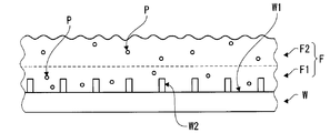
- FIG. 7 is a schematic view of the surface of the substrate before the start of the spin dry process.
- a convex circuit pattern W2 is formed on the upper surface W1 of the substrate W.
- a liquid film F of the rinse liquid is held on the upper surface W1.
- the liquid film F contains particles P separated from the upper surface W1 of the substrate W.
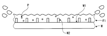
- FIG. 8 is a schematic diagram of the substrate W during the spin dry process. Centrifugal force acts on the upper layer region F2 of the liquid film, so that it is scattered and excluded from the substrate W. However, the lower layer region F1 in the vicinity of the substrate rotates in the same direction as the substrate W at substantially the same speed in conjunction with the substrate W. For this reason, the flow of the processing liquid does not occur in the lower layer region F1, and the processing liquid stays. As a result, the lower layer region F1 is not excluded from the substrate, and the particles P in the lower layer region F1 remain on the substrate W. Therefore, the substrate W cannot be cleaned with high accuracy.
- the present invention aims to solve the above problems. That is, it is an object of the present invention to provide a substrate processing method and a substrate processing apparatus capable of satisfactorily removing particles present in the liquid near the substrate.
- a substrate processing method includes a processing liquid supply step of supplying a processing liquid to the one main surface of the substrate in a state where the substrate is supported with one main surface facing upward.
- a liquid film holding step for holding a liquid film of a processing solution on the one main surface of the substrate, one surface provided with a plurality of first openings, and one or more second communicating with the plurality of first openings.
- a contact step of bringing the one surface into contact with the upper surface of the liquid film among members having another surface provided with an opening.
- a substrate processing method is the substrate processing method according to the first aspect, wherein, in the contacting step, two or more first openings among the plurality of first openings are formed on an upper surface of the liquid film. Contact.
- the substrate processing method according to the third aspect is the substrate processing method according to the first aspect or the second aspect, and the member is heated in the contact step.
- a substrate processing method is the substrate processing method according to any one of the first to third aspects, wherein in the contacting step, the member is processed according to the thickness of the liquid film. Adjust the height position.
- a substrate processing apparatus includes a substrate support unit that supports a substrate with one main surface facing upward, and a process of supplying a processing liquid to the one main surface of the substrate supported by the substrate support unit.
- a substrate processing apparatus is the substrate processing apparatus according to the fifth aspect, wherein the member includes a flat plate provided with a plurality of through holes penetrating in the thickness direction.
- a substrate processing apparatus is the substrate processing apparatus according to the fifth aspect, wherein the member includes a mesh member having a plurality of gap portions communicating in the thickness direction.
- a substrate processing apparatus is the substrate processing apparatus according to any one of the fifth to seventh aspects, further comprising an application unit that applies a voltage to the member, and the member Includes a heating element that generates heat in response to application of a voltage.
- the substrate processing apparatus is the substrate processing apparatus according to any one of the fifth to eighth aspects, further comprising a member cleaning unit that cleans the member.
- a substrate processing method is a substrate processing method executed in a predetermined atmosphere, wherein a processing liquid is supplied to the upper surface of the substrate while the substrate is supported in a substantially horizontal state, and the substrate is supplied to the substrate.
- a processing liquid supply step for performing predetermined substrate processing a liquid film holding step for holding a liquid film of the processing liquid on the upper surface of the substrate, and a flat plate for contacting a flat plate having a plurality of through holes formed in the liquid film And a contact process.
- the flat plate is brought into contact with the liquid film in the flat plate contact step.
- convection from the vicinity of the substrate toward the liquid surface is formed by the interface free energy generated at the three-phase interface where the treatment liquid, the atmosphere, and the inner edges of the through holes intersect.
- the processing liquid in the vicinity of the substrate moves to the surface of the liquid film and contacts the inner edge of the through hole.
- the particles in the processing liquid are captured by the flat plate. In this way, it is possible to efficiently remove particles in the vicinity of the substrate that could not be eliminated by conventional spin dry.
- the substrate processing method in the flat plate contact step, the three-phase interface where the processing liquid, the atmosphere, and the inner edge of the through hole intersect with each other is generated at a plurality of locations on the surface of the liquid film.
- the substrate processing method is characterized in that a flat plate is brought into contact with the liquid film of the processing liquid.
- the three-phase interface is generated at a plurality of locations of the liquid film, the number of locations where the treatment liquid contacts the flat plate through-holes increases. As a result, particles can be captured more efficiently by the flat plate.
- a substrate processing method is a substrate processing method, wherein the flat plate is heated in the flat plate heating step.
- a substrate processing method is a substrate processing method in which, in the flat plate contact step, the position of the flat plate is set according to the thickness of the liquid film in the liquid film holding step.
- the position of the flat plate in the flat plate contact step can be set to a position corresponding to the thickness of the liquid film.
- a substrate processing apparatus is a substrate processing apparatus that performs substrate processing in a predetermined atmosphere, and includes a substrate support unit that supports the substrate in a substantially horizontal state, and a substrate that is supported by the substrate support unit.
- Processing liquid supply means for supplying a processing liquid to the upper surface of the substrate and forming a liquid film of the processing liquid for processing the substrate, a flat plate having a mesh member in which a plurality of through holes are formed, a position in contact with the liquid film, The flat plate moving means for moving the flat plate between the separation positions not in contact with the liquid film, and the liquid film of the treatment liquid is formed, and then the flat plate is moved to the liquid film by controlling the flat plate moving means. And a control means for controlling the particles to move to a position in contact with the surface of the mesh member and attach the particles to the side surface of the through hole of the mesh member.
- the processing liquid in the vicinity of the substrate moves to the surface of the liquid film and contacts the inner edge of the through hole of the mesh member. Thereby, the particles in the processing liquid are captured by the flat plate. In this way, it is possible to efficiently remove particles in the vicinity of the substrate that could not be eliminated by conventional spin dry.
- particles near the substrate can be removed satisfactorily.
- FIG. 3 is a plan view of a member 13.
- FIG. It is typical sectional drawing of the member 13 seen from the III-III cross section in FIG. It is a flowchart for demonstrating a board
- FIG. 1 is a cross-sectional view schematically showing the configuration of a substrate processing apparatus according to an embodiment of the present invention.
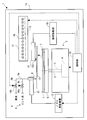
- the substrate processing apparatus 1 includes a substrate rotating mechanism 2 for holding and rotating a substrate W as an example of a substrate in a substantially horizontal posture, and a chemical solution and an upper surface (front surface) of the substrate W held by the substrate rotating mechanism 2. It has a liquid supply mechanism 3 for selectively supplying a rinsing liquid and a housing 1a.
- the housing 1a includes a substrate rotation mechanism 2, a liquid supply mechanism 3, an arm 11 (described later), a nozzle moving mechanism 12 (described later), an arm 14 (described later), a member moving unit 15 (described later), and a member cleaning unit 17 (described later). ) Etc. are stored.
- the substrate rotating mechanism 2 for example, a sandwiching type is adopted.
- the substrate rotation mechanism 2 includes a motor 4, a spin shaft 5 integrated with a drive shaft of the motor 4, and a disc-shaped spin base 6 attached to the upper end of the spin shaft 5 almost horizontally. And a plurality of clamping members 7 provided at substantially equiangular intervals at a plurality of locations on the periphery of the spin base 6.
- the substrate W can be held in a substantially horizontal posture by the plurality of holding members 7.
- the substrate W can be rotated around the central axis of the spin shaft 5 while maintaining the substantially horizontal posture together with the spin base 6 by the driving force.
- the substrate rotation mechanism 2 functions as a substrate support unit that supports the substrate W with one main surface facing upward.
- the mode of supporting the substrate W may be a suction mode that vacuum-sucks the lower surface of the substrate W in addition to the sandwiching mode described above.
- the posture of the substrate W to be supported is not limited to a strict horizontal posture, and may be a posture inclined from the horizontal. If the liquid film of the processing liquid is held on the upper surface of the substrate W, particles near the substrate W can be efficiently removed by the substrate processing method described later. For this reason, the tolerance of the inclination of the substrate W is determined according to the lyophilicity of the substrate W with respect to the processing liquid and the viscosity of the processing liquid.
- the liquid supply mechanism 3 includes a nozzle 8, a supply pipe 9a connected to the nozzle 8, a branch pipe 9b and a branch pipe 9c connected to the supply pipe 9a, and a valve 10b interposed in the middle of the branch pipe 9b. And a valve 10c interposed in the middle of the branch pipe 9c.
- a chemical liquid such as a cleaning liquid is supplied to the branch pipe 9b from a chemical liquid supply means (not shown).
- a rinsing liquid such as DIW is supplied to the branch pipe 9c from a rinsing liquid supply means (not shown).
- the rinsing liquid is used as a processing liquid that comes into contact with the member 13 described later. Therefore, the liquid supply mechanism 3 functions as a processing liquid supply unit that supplies the processing liquid to the upper surface of the substrate W supported by the substrate support unit.
- the nozzle 8 is attached to the tip of the arm 11.
- the arm 11 extends horizontally above the substrate rotation mechanism 2.
- a nozzle moving mechanism 12 including a motor and the like is coupled to the arm 11. With the nozzle moving mechanism 12, the arm 11 can be swung in a horizontal plane around the axis set on the side of the substrate rotating mechanism 2. As the arm 11 swings, the nozzle 8 moves horizontally above the substrate rotation mechanism 2.
- a member 13 is provided above the substrate rotation mechanism 2.
- the member 13 is a circular member having an outer diameter smaller than that of the substrate W, and a large number of gaps 135 (FIG. 2 described later) are formed.
- a protrusion 133 is fixed to the upper surface of the member 13.
- the member 13 is detachably attached to the distal end portion of the arm 14 that extends horizontally above the substrate rotation mechanism 2 via the protrusion 133.
- a member moving unit 15 including a motor or the like is coupled to the arm 14. The member moving unit 15 can swing the arm 14 in a horizontal plane around an axis set to the side of the substrate rotation mechanism 2.
- the member 13 By swinging the arm 14, the member 13 can be moved horizontally above the substrate rotation mechanism 2, and the standby position spaced laterally from the substrate rotation mechanism 2 and the center of the member 13 are on the spin base 6. It can be moved between a position coincident with the rotation center C of the substrate W.
- the arm 14 can be moved up and down by the member moving part 15. As the arm 14 moves up and down, the member 13 can be moved up and down, and the lower surface of the member 13 can be positioned at a height close to the upper surface of the substrate W. Thereby, the member 13 can be overlaid on the liquid film of the substrate W during the substrate processing.
- the substrate processing apparatus 1 has a member cleaning unit 17.
- the member cleaning unit 17 is a hollow housing for cleaning the member 13, and includes a loading / unloading port (not shown) for loading / unloading the member 13.
- a plurality of sprays 18 that discharge cleaning liquid toward the member 13 are disposed inside the member cleaning unit 17.
- the member moving unit 15 can move the member 13 from above the substrate rotating mechanism 2 to the inside of the member cleaning unit 17 by swinging and raising the arm 14. When the member 13 is stored in the member cleaning unit 17, the grip of the member 13 by the arm 14 is released.
- the substrate processing apparatus 1 includes a control unit 16 composed of a microcomputer.
- the control unit 16 controls driving of the motor 4, the nozzle moving mechanism 12, and the member moving unit 15 according to a predetermined program, and controls opening and closing of the valve 10b and the valve 10c. Further, the control unit 16 controls the timing of discharging the cleaning liquid from the spray 18.
- the control unit 16 is electrically connected to each unit included in the substrate processing apparatus 1 and controls the operation of each unit of the substrate processing apparatus 1 while executing various arithmetic processes.
- the control unit 16 is configured by a general computer in which, for example, a CPU, a ROM, a RAM, a storage device, and the like are interconnected via a bus line.
- the ROM stores basic programs and the like, and the RAM is used as a work area when the CPU performs predetermined processing.
- the storage device is configured by a non-volatile storage device such as a flash memory or a hard disk device.
- a program is stored in the storage device, and various functions are realized when a CPU as a main control unit performs arithmetic processing according to a procedure described in the program.
- the program is usually used by being stored in advance in a memory such as a storage device, but is provided in a form (program product) recorded on a recording medium such as a CD-ROM or DVD-ROM or an external flash memory. (Or provided by downloading from an external server via a network) and may be additionally stored in a memory such as a storage device.
- a memory such as a storage device
- the functions realized in the control unit 16 may be realized in hardware by a dedicated logic circuit or the like.
- the input unit includes various switches, a touch panel, and the like, and receives various input setting instructions from an operator.
- the display unit includes a liquid crystal display device, a lamp, and the like, and displays various types of information under the control of the CPU.
- the communication unit has a data communication function via a LAN or the like.
- control unit 16 controls the liquid supply mechanism 3 to form a liquid film of the processing liquid on the upper surface of the substrate W, and controls the member moving unit 15 to control the member 13 The lower surface is brought into contact with the upper surface of the liquid film of the processing liquid.
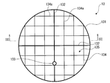
- FIG. 2 is a plan view schematically showing the configuration of the member 13.
- the member 13 includes a circular frame body 131 in a plan view, a support portion 132 disposed inside the frame body 131 so as to be orthogonal to the radial direction of the frame body 131, a projection 133 fixed to the support portion 132, a frame
- the mesh member 134 is supported by the support portion 132 inside the body 131.
- the mesh member 134 is formed by intersecting a plurality of bars 134a.
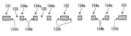
- FIG. 3 is a schematic cross-sectional view of the member 13 viewed from the III-III cross section in FIG.
- Each bar 134a is rectangular in cross-sectional view and has a side surface 134b.
- the side surface 134b is used when capturing particles in the liquid film on the substrate W.
- the side surface 134b is desirably hydrophilic so that particles can be captured well.
- the frame 131 is also rectangular in cross-sectional view and has a side surface 131b.
- the support portion 132 is also rectangular in cross-sectional view and has a side surface 132b.
- the side surface 131b of the frame 131 and the side surface 132b of the support portion 132 are also used for capturing particles in the same manner as the side surface 134b of the bar 134a.
- the side surface 134b of the bar 134a is used for capturing particles. An aspect is explained in full detail.
- the member 13 has a lower surface provided with a plurality of first openings and an upper surface provided with a plurality of second openings communicating with the plurality of first openings.
- a plurality of gaps 135 are provided between the plurality of first openings and the plurality of second openings, respectively. Specifically, a location surrounded by the adjacent bars 134a and 134a, a location surrounded by the bars 134a and the frame 131, a location surrounded by the bars 134a and the support portion 132, and the bar 134a
- a space 135 is formed between the upper surface and the lower surface of the member 13 at a location surrounded by the frame 131 and the support portion 132.
- the width of the frame body 131 and the support portion 132 is larger than the width of the bar 134a, and the frame body 131 and the support portion 132 have higher rigidity than the bar 134a.
- the projection part 133 is attached to the support part 132 with such high rigidity. For this reason, even when the protrusion 133 is attached to the arm 14 and the member 13 is moved, the member 13 is hardly deformed.
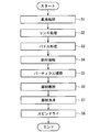
- FIG. 4 is a flowchart when the substrate processing according to the present embodiment is performed. It is assumed that the substrate W is already fixed to the spin base 6 and that the member 13 is located at a standby position separated from the upper side of the substrate W.
- the control unit 16 executes the chemical solution processing S1. Specifically, the control unit 16 rotates the substrate W at a predetermined chemical solution processing speed (for example, 1000 rpm). At the same time, the nozzle moving mechanism 12 is controlled to move the arm 11 to move the nozzle 8 to a position immediately above the rotation center C of the substrate W. In this state, the valve 10b is opened. Accordingly, the chemical solution is supplied from the nozzle 8 toward the rotation center C of the substrate W. The supplied chemical solution spreads from the rotation center C of the substrate W toward the periphery of the substrate W by centrifugal force, and the entire upper surface of the substrate W is processed with the chemical solution.
- a predetermined chemical solution processing speed for example, 1000 rpm.
- the nozzle moving mechanism 12 is controlled to move the arm 11 to move the nozzle 8 to a position immediately above the rotation center C of the substrate W.
- the valve 10b is opened. Accordingly, the chemical solution is supplied from the nozzle 8 toward the rotation center C of the substrate W.
- the control unit 16 executes a rinse treatment step S2. Specifically, the control unit 16 closes the valve 10b and opens the valve 10c. Accordingly, the rinse liquid is supplied from the nozzle 8 toward the rotation center C of the substrate W. The supplied rinsing liquid diffuses from the rotation center C of the substrate W toward the peripheral edge of the substrate W and scatters from the peripheral edge of the substrate W to the outside. As a result, the chemical liquid that has adhered to the upper surface of the substrate W is replaced with the rinse liquid.
- the rinse treatment step S2 corresponds to a treatment liquid supply step of supplying a treatment liquid to the one principal surface of the substrate W in a state where the substrate W is supported with one principal surface facing upward.
- the control unit 16 After completion of the rinsing process S2, the control unit 16 starts the paddle formation process S3. That is, the motor 4 is controlled to decelerate and stop the rotation of the substrate W. Alternatively, the speed is reduced to a rotational speed (for example, 10 rpm) that can be equated with the stop.
- the controller 16 continues to supply the rinse liquid to the rotation center C of the substrate W. As a result, the rinse liquid stays on the upper surface of the substrate W due to the surface tension of the rinse liquid, and a paddle-like liquid film is formed. After the liquid film is formed on the upper surface of the substrate W, the controller 16 closes the valve 10c to stop the supply of the rinsing liquid to the substrate W.
- the paddle formation step S3 corresponds to a liquid film holding step for holding the liquid film of the processing liquid on the upper surface of the substrate W.
- control part 16 performs contact process S4. Specifically, the control unit 16 controls the member moving unit 15 to horizontally move the arm 14 until the member 13 is positioned immediately above the substrate W while maintaining the paddle-like liquid film on the upper surface of the substrate W. . Next, the control unit 16 controls the member moving unit 15 to lower the arm 14 to a height at which the lower surface of the member 13 contacts the upper surface of the liquid film on the substrate W.
- FIG. 5 is a schematic diagram showing a state in which the member 13 is in contact with the liquid film F.
- a liquid film F is held on the substrate W.
- the liquid surface F12 of the liquid film F is exposed to the atmosphere A in the housing 1a of the substrate processing apparatus 1 in the gap portion 135 of the member 13.
- the lower surface of the member 13 is in liquid-tight contact with the liquid surface F12.
- the liquid level F12 is also in contact with the side surface 134b of the member 13.
- a three-phase interface is formed where the liquid film F, the atmosphere A immediately above the liquid film F, and the bar 134a intersect. Interfacial free energy is generated at the contact portion 134c.
- the member 13 is a circular member having an outer diameter smaller than the substrate W by a minute amount. For this reason, in contact process S4, all the some 1st opening which the member 13 has contacts the upper surface (liquid level F12) of the liquid film F, and the liquid level F12 reaches
- the higher the temperature of the member 13 for example, the bar 134a
- the liquid flow from the bottom to the top in the liquid film F can be made stronger, so that the amount of particles captured by the side surface 134b can be increased. Therefore, in the contact step S4 and the particle capturing step S5, it is desirable to maintain the bar 134a at a temperature higher than room temperature by heating.
- the member 13 when the member 13 includes a heating element that generates heat in response to application of a voltage, the member 13 is heated by applying a voltage to the member 13 by an application unit (not shown).
- an application unit not shown
- the structure in which the member 13 contains a heating wire is mentioned.
- the height position of the member 13 may be determined according to the hydrophobicity of the substrate W. Specifically, when the hydrophobicity of the upper surface of the substrate W is low, the height of the member 13 is set low. Conversely, when the hydrophobicity is high, the height of the member 13 is set high. Thus, in the contact step S4, the height position of the member 13 is adjusted according to the thickness of the liquid film F. Further, when the thickness of the liquid film F varies during the contact step S4 and the particle capturing step S5, the height position of the member 13 may be adjusted according to the variation of the thickness of the liquid film F.
- control part 16 performs member removal process S6. That is, the control unit 16 controls the member moving unit 15 to raise the arm 14. As a result, the member 13 is detached from the liquid surface F12. Next, the control unit 16 controls the member moving unit 15 to rotate the arm 14 to move the member 13 from a position directly above the substrate W.
- the control part 16 performs member cleaning process S7. That is, the control unit 16 controls the member moving unit 15 to raise and lower and rotate the arm 14 to store the member 13 in the member cleaning unit 17. Then, a predetermined cleaning fluid such as a cleaning liquid is sprayed from the spray 18 toward the member 13 to remove particles adhering to the member 13 during the particle capturing step S5. In addition, you may dry the member 13 after washing
- the control unit 16 executes the spin dry step S8. That is, the control unit 16 controls the motor 4 to rotate the spin base 6 at a high speed. As a result, the liquid film F held on the substrate W is scattered by centrifugal force and is collected in a cup (not shown) surrounding the spin base 6. As described above, even if spin drying is performed, it is difficult to remove the liquid film region (lower layer region F1) near the substrate W by scattering from the substrate W. However, in this embodiment, the spin drying step S8 is performed. Before executing the particle capturing step S5. Thereby, the particles contained in the lower layer region F1 are removed from the substrate W. For this reason, even if the rinse liquid in the lower layer region F1 remains on the substrate W after the spin dry step S8, the residual liquid contains almost no particles. Therefore, particles do not remain on the upper surface of the substrate W. Thereby, high substrate cleaning performance can be realized.
- the particle capturing step S5 is executed only once.
- the steps from the paddle formation step S3 to the member removal step S6 may be repeatedly executed. By doing so, particles can be removed from the liquid film F held on the substrate W a plurality of times. Thereby, the amount of particles contained in the liquid film F can be further reduced. As a result, the cleaning performance of the substrate can be improved.
- the contact step S4 and the particle capturing step S5 are performed with the member 13 held by the arm 14.
- a fixing member for fixing the member 13 may be provided on the spin base 6 separately from the clamping member 7 for fixing the substrate W. Accordingly, the member 13 can be detached from the arm 14 and fixed on the spin base 6 in the contact step S4. And particle capture process S5 can be performed in the state where member 13 was left on spin base 6.
- the rinsing liquid may be supplied from the nozzle 8 toward the liquid film F. Further, the rotation speed of the substrate W may be varied during the particle capturing step S5. By adding such a process, the liquid film F can be vibrated during the execution of the particle capturing process S5. Thereby, particles existing in the vicinity of the substrate W can be efficiently attached to the side surface 134b of the mesh member 134.
- the mode in which the member 13 has the lower surface provided with the plurality of first openings and the upper surface provided with the plurality of second openings communicating with the plurality of first openings has been described. It is not something that can be done.
- the member only needs to have one surface provided with a plurality of first openings and another surface provided with one or more second openings communicating with the plurality of first openings, and is different from the above embodiment. It may be a configuration.
- the member has one surface provided with a plurality of first openings and another surface provided with one second opening communicating with the plurality of first openings, and a gap portion branched into the inside is formed. May be.
- the member has one surface (for example, a lower surface) provided with a plurality of first openings and another surface (an upper surface or a top surface) provided with one second opening communicating with the plurality of first openings.
- a plurality of surfaces such as side surfaces).
- the shape of the lower surface of the member one surface in contact with the treatment liquid among the members
- the shape of the lower surface of the member may be an uneven shape or a curved shape.
- FIG. 6 is a plan view of a member 13A according to a modification.
- the member 13A may be a flat plate 139 (so-called punching plate) having a plurality of through holes 135A penetrating in the thickness direction.
- the outer shape of the member 13A in plan view may be rectangular.
- the present invention can be effectively used for substrate processing.
Landscapes
- Physics & Mathematics (AREA)
- General Physics & Mathematics (AREA)
- Cleaning Or Drying Semiconductors (AREA)
Abstract
基板の上面に付着したパーティクル等を良好に除去することができる基板処理方法および当該方法を実行する基板処理装置を提供する。基板Wの上面にリンス液の液膜Fを形成するパドル形成工程S3と、複数の空隙部135が形成されたメッシュ部材134を備えた部材13を液膜Fに接触させる接触工程S4と、リンス液、雰囲気Aおよび部材13のメッシュ部材134の内縁が相交わる三相界面に発生する界面自由エネルギーによって当該リンス液の液膜F内に対流を生じさせてメッシュ部材134の側面134bにパーティクルを捕捉させるパーティクル捕捉工程S5と、が順次実行される。
Description
発明は、基板に対する処理液を用いた処理のための基板処理装置および基板処理方法に関する。処理の対象となる基板には、たとえば、半導体基板、液晶表示装置用基板、プラズマディスプレイ用基板、FED(Field Emission Display)用基板、光ディスク用基板、磁気ディスク用基板、光磁気ディスク用基板、フォトマスク用基板などが含まれる。より具体的には、基板の表面に付着した異物を除去するための基板洗浄技術に関する。
通常、基板の洗浄は以下のように行われている。まず、回転する基板の表面にSC1等の薬液を供給することにより、基板の表面に付着しているパーティクルを溶解またはリフトオフさせて離脱させる(薬液供給工程)。次に、基板の表面に純水等のリンス液を供給することにより、リンス液の液膜を基板の表面に形成して前記パーティクルをリンス液の液膜に溶解させる(リンス工程)。最後に、基板を高速回転させることによりリンス液の液膜に遠心力を作用させて、この液膜を基板の表面から排除する。これにより、前記パーティクルがリンス液ごと基板の表面から除去される(スピンドライ工程)。
図7は、スピンドライ工程開始前の基板の表面の模式図である。基板Wの上面W1には凸状の回路パターンW2が形成されている。上面W1にはリンス液の液膜Fが保持されている。液膜Fの中には基板Wの上面W1から離脱したパーティクルPが含まれている。
図8はスピンドライ工程を実施中の基板Wの模式図である。液膜の上層領域F2には遠心力が作用するため飛散して基板Wから排除される。しかし、基板近傍の下層領域F1は基板Wに連動して基板Wと同一方向にほぼ同一の速度で回転する。このため下層領域F1中では処理液の流れが発生せず処理液が滞留してしまう。この結果、下層領域F1が基板から排除されず、下層領域F1中のパーティクルPが基板Wに残留する。したがって、基板Wを高い精度で洗浄することができない。
本発明は上記課題を解決することを目的とする。すなわち基板近傍の液中に存在するパーティクルを良好に除去することが可能な基板処理方法および基板処理装置を提供することである。
上記課題を解決するため、第1の態様にかかる基板処理方法は、一主面を上方に向けて基板を支持した状態で、前記基板の前記一主面に処理液を供給する処理液供給工程と、前記基板の前記一主面に処理液の液膜を保持する液膜保持工程と、複数の第1開口が設けられた一面と、前記複数の第1開口に連通する1以上の第2開口が設けられた他の面と、を有する部材のうち、前記一面を前記液膜の上面に接触させる接触工程と、を含む。
第2の態様にかかる基板処理方法は、第1の態様にかかる基板処理方法であって、前記接触工程において、前記複数の第1開口のうち2以上の第1開口が前記液膜の上面に接触する。
第3の態様にかかる基板処理方法は、第1の態様または第2の態様にかかる基板処理方法であって、前記接触工程において、前記部材を加熱する。
第4の態様にかかる基板処理方法は、第1の態様から第3の態様のいずれか1つにかかる基板処理方法であって、前記接触工程において、前記液膜の厚みに応じて前記部材の高さ位置を調整する。
第5の態様にかかる基板処理装置は、一主面を上方に向けて基板を支持する基板支持部と、前記基板支持部に支持された前記基板の前記一主面に処理液を供給する処理液供給部と、複数の第1開口が設けられた一面と、前記複数の第1開口に連通する1以上の第2開口が設けられた他の面と、を有する部材と、前記部材を移動させる部材移動部と、前記処理液供給部を制御して前記一主面に前記処理液の液膜を形成し、前記部材移動部を制御して前記部材の一面を前記液膜の上面に接触させる制御部と、を備える。
第6の態様にかかる基板処理装置は、第5の態様にかかる基板処理装置であって、前記部材は、厚さ方向に貫通する複数の貫通孔が設けられた平板を含む。
第7の態様にかかる基板処理装置は、第5の態様にかかる基板処理装置であって、前記部材は、厚さ方向に連通した複数の空隙部を有するメッシュ部材を含む。
第8の態様にかかる基板処理装置は、第5の態様から第7の態様のいずれか1つにかかる基板処理装置であって、前記部材に電圧を印加する印加部、をさらに備え、前記部材は電圧の印加に応じて発熱する発熱体を含む。
第9の態様にかかる基板処理装置は、第5の態様から第8の態様のいずれか1つにかかる基板処理装置であって、前記部材を洗浄する部材洗浄部、をさらに備える。
他の態様にかかる基板処理方法は、所定の雰囲気の中で実行される基板処理方法であって、基板を略水平状態に支持した状態で前記基板の上面に処理液を供給し、前記基板に所定の基板処理を実行する処理液供給工程と、前記基板の上面に前記処理液の液膜を保持する液膜保持工程と、前記液膜に複数の貫通孔が形成された平板を接触させる平板接触工程と、を含む基板処理方法である。
この態様によれば、平板接触工程で前記平板を液膜に接触させる。このとき、処理液、雰囲気および貫通孔の内縁が相交わる三相界面で発生する界面自由エネルギーによって基板近傍から液面に向かう対流が形成される。この対流により基板近傍の処理液が液膜の表面に移動し貫通孔の内縁に接触する。これにより、処理液中のパーティクルが平板に捕獲される。こうして、従来のスピンドライでは排除できなかった基板近傍のパーティクルを効率よく除去することが可能になる。
他の態様にかかる基板処理方法は、前記平板接触工程では、前記処理液、前記雰囲気および前記貫通孔の内縁が相交わる三相界面を前記液膜の表面の複数箇所で発生させるように、前記平板を前記処理液の液膜に接触させることを特徴とする基板処理方法である。
この態様によれば、三相界面が前記液膜の複数箇所で発生するため、処理液が平板の貫通孔に接触する箇所が多くなる。この結果、平板によるパーティクルの捕獲がより効率的に行える。
他の態様にかかる基板処理方法は、前記平板加熱工程では前記平板を加熱することを特徴とする基板処理方法である。
この態様によれば、液膜中により強力な対流を発生させることができるのでパーティクルをより効率的に捕獲することができる。
他の態様にかかる基板処理方法は、前記平板接触工程では、前記液膜保持工程における前記液膜の厚みに応じて前記平板の位置を設定することを特徴とする基板処理方法である。
この態様によれば、平板接触工程における平板の位置を液膜の厚みに応じた位置に設定することが可能になる。
他の態様にかかる基板処理装置は、所定の雰囲気の中で基板処理を実行する基板処理装置であって、基板を略水平状態に支持する基板支持手段と、前記基板支持手段に支持された基板の上面に処理液を供給し前記基板を処理する処理液の液膜を形成する処理液供給手段と、複数の貫通孔が形成されたメッシュ部材を有する平板と、前記液膜に接する位置と、前記液膜に接しない離隔位置との間で、前記平板を移動させる平板移動手段と、前記処理液の液膜が形成された後、前記平板移動手段を制御することによって前記平板を前記液膜に接する位置に移動させ、前記液膜中に存在するパーティクルを前記メッシュ部材の貫通孔の側面に付着させて捕捉する制御を行う制御手段と、を備える基板処理装置である。
この態様によれば、基板近傍の処理液が液膜の表面に移動しメッシュ部材の貫通孔の内縁に接触する。これにより、処理液中のパーティクルが平板に捕獲される。こうして、従来のスピンドライでは排除できなかった基板近傍のパーティクルを効率よく除去することが可能になる。
各態様の発明によれば、基板近傍のパーティクルを良好に除去することが可能になる。
以下、本発明の一実施の形態に係る基板処理装置について図面を参照しながら説明する。
図1は、本発明の一実施形態に係る基板処理装置の構成を図解的に示す断面図である。基板処理装置1は、基板の一例としての基板Wをほぼ水平な姿勢に保持して回転させるための基板回転機構2と、基板回転機構2に保持された基板Wの上面(表面)に薬液およびリンス液を選択的に供給するための液体供給機構3と、筐体1aとを有している。筐体1aには、基板回転機構2、液体供給機構3、アーム11(後述)、ノズル移動機構12(後述)、アーム14(後述)、部材移動部15(後述)、部材洗浄部17(後述)などが格納されている。
基板回転機構2としては、たとえば、挟持式のものが採用されている。具体的には、基板回転機構2は、モータ4と、このモータ4の駆動軸と一体化されたスピン軸5と、スピン軸5の上端にほぼ水平に取り付けられた円板状のスピンベース6と、スピンベース6の周縁部の複数箇所にほぼ等角度間隔で設けられた複数個の挟持部材7とを備えている。
複数個の挟持部材7により、基板Wをほぼ水平な姿勢で挟持することができる。この状態で、モータ4を駆動すると、その駆動力によって、そのスピンベース6とともに、基板Wをほぼ水平な姿勢を保った状態でスピン軸5の中心軸線まわりに回転することができる。
基板回転機構2が、一主面を上方に向けて基板Wを支持する基板支持部として機能する。基板Wを支持する態様は、上述した挟持式の態様の他、基板Wの下面を真空吸引する吸引式の態様であってもよい。また、支持される基板Wの姿勢も、厳密な水平姿勢に限られず、水平から傾いた姿勢であってもよい。基板Wの上面に処理液の液膜が保持される状態であれば、後述する基板処理方法により基板W近傍のパーティクルを効率よく除去することができる。このため、基板Wの傾きの許容度は、処理液に対する基板Wの親液性や処理液の粘性に応じて定まる。
液体供給機構3は、ノズル8と、ノズル8に接続された供給管9aと、供給管9aに接続された枝管9bおよび枝管9cと、枝管9bの途中部に介装されたバルブ10bと、枝管9cの途中部に介装されたバルブ10cとを備えている。枝管9bへは図示しない薬液供給手段から洗浄液等の薬液が供給される。枝管9cへは図示しないリンス液供給手段からDIW等のリンス液が供給される。バルブ10bおよびバルブ10cの一方を開放し他方を閉止することにより、薬液とリンス液とをノズル8に向けて選択的に供給することができる。
本実施形態では、リンス液が後述する部材13に接液される処理液として用いられる。したがって、液体供給機構3は、基板支持部に支持された基板Wの上面に処理液を供給する処理液供給部として機能する。
ノズル8は、アーム11の先端部に取り付けられている。アーム11は、基板回転機構2の上方で水平に延びている。アーム11には、モータなどを含むノズル移動機構12が結合されている。ノズル移動機構12により、アーム11を基板回転機構2の側方に設定された軸線を中心に水平面内で揺動させることができる。アーム11の揺動に伴ってノズル8は基板回転機構2の上方で水平移動する。
基板回転機構2の上方には部材13が設けられている。部材13は基板Wよりも微小量小さな外径を有する円形部材であり、多数の空隙部135(後述する図2)が形成されている。部材13の上面には突起部133が固着されている。部材13は突起部133を介して基板回転機構2の上方で水平に延びるアーム14の先端部に着脱自在に取り付けられる。アーム14には、モータなどを含む部材移動部15が結合されている。部材移動部15はアーム14を基板回転機構2の側方に設定された軸線を中心に水平面内で揺動させることができる。アーム14を揺動させることによって、部材13を基板回転機構2の上方で水平移動させることができ、基板回転機構2から側方に離隔した待機位置と、部材13の中心がスピンベース6上の基板Wの回転中心Cと一致する位置との間で移動させることができる。
部材移動部15により、アーム14を昇降させることができる。アーム14の昇降に伴って、部材13を昇降させ、部材13の下面を基板Wの上面に近接する高さに位置させることができる。これにより、基板処理時に、部材13を基板Wの液膜の上に重ねることができる。
基板処理装置1は部材洗浄部17を有している。部材洗浄部17は部材13を洗浄するための中空の筐体であり、部材13を搬入出するための開閉可能な図示しない搬入出口を備えている。部材洗浄部17の内部には部材13に向けて洗浄液を吐出する複数のスプレー18が配設されている。部材移動部15は、アーム14を搖動させかつ上昇させることにより、部材13を基板回転機構2の上方から部材洗浄部17の内部に移動させることができる。部材13が部材洗浄部17の内部に格納されるとアーム14による部材13の把持が解除される。
基板処理装置1は、マイクロコンピュータで構成される制御部16を備えている。制御部16は、予め定められたプログラムに従って、モータ4、ノズル移動機構12、および部材移動部15の駆動を制御し、また、バルブ10bおよびバルブ10cの開閉を制御する。さらに、制御部16はスプレー18からの洗浄液吐出タイミングを制御する。
制御部16は、基板処理装置1が備える各部と電気的に接続されており、各種の演算処理を実行しつつ基板処理装置1の各部の動作を制御する。制御部16は、例えば、CPU、ROM、RAM、記憶装置等がバスラインを介して相互接続された一般的なコンピュータによって構成されている。ROMは基本プログラム等を格納しており、RAMはCPUが所定の処理を行う際の作業領域として供される。記憶装置は、フラッシュメモリ、あるいは、ハードディスク装置等の不揮発性の記憶装置によって構成されている。記憶装置にはプログラムが格納されており、このプログラムに記述された手順に従って、主制御部としてのCPUが演算処理を行うことにより、各種機能が実現されるように構成されている。プログラムは、通常、予め記憶装置等のメモリに格納されて使用されるものであるが、CD-ROMあるいはDVD-ROM、外部のフラッシュメモリ等の記録媒体に記録された形態(プログラムプロダクト)で提供され(あるいは、ネットワークを介した外部サーバからのダウンロードなどにより提供され)、追加的に記憶装置等のメモリに格納されるものであってもよい。なお、制御部16において実現される一部あるいは全部の機能は、専用の論理回路等でハードウエア的に実現されてもよい。
また、制御部では、入力部、表示部、通信部もバスラインに接続されている。入力部は、各種スイッチ、タッチパネル等により構成されており、オペレータから各種の入力設定指示を受け付ける。表示部は、液晶表示装置、ランプ等により構成されており、CPUによる制御の下、各種の情報を表示する。通信部は、LAN等を介したデータ通信機能を有する。
後述するパドル形成工程S3および接触工程S4では、制御部16が、液体供給機構3を制御して基板Wの上面に処理液の液膜を形成し、部材移動部15を制御して部材13の下面を処理液の液膜の上面に接触させる。
図2は、部材13の構成を図解的に示す平面図である。部材13は平面視で円形の枠体131と、枠体131の内部で枠体131の径方向に直交して配置された支持部132と、支持部132に固着された突起部133と、枠体131の内部で支持部132に支持されたメッシュ部材134とで構成されている。メッシュ部材134は複数のバー134aを交差させることで形成される。
図3は、図2におけるIII-III断面から視た部材13の模式的な断面図である。各バー134aは、断面視で矩形状であり、側面134bを有している。側面134bは基板W上の液膜中のパーティクルを捕獲する際に使用される。側面134bはパーティクルの捕獲が良好に行えるよう、親水性であることが望ましい。枠体131も、断面視で矩形状であり、側面131bを有している。また、支持部132も、断面視で矩形状であり、側面132bを有している。枠体131の側面131bおよび支持部132の側面132bもバー134aの側面134bと同様にパーティクルの捕獲に利用されるが、以下ではこれらの代表としてバー134aの側面134bがパーティクルの捕獲に利用される態様について詳述する。
部材13は、複数の第1開口が設けられた下面と、複数の第1開口に連通する複数の第2開口が設けられた上面と、を有する。そして、複数の第1開口と複数の第2開口との間には、それぞれ結ぶ複数の空隙部135が設けられる。具体的には、隣接するバー134aとバー134aとに囲まれた箇所、バー134aと枠体131とに囲まれた箇所、バー134aと支持部132とに囲まれた箇所、および、バー134aと枠体131と支持部132とに囲まれた箇所、において、部材13の上面と下面との間に空隙部135が形成される。
図3からも分かるように、枠体131および支持部132の幅はバー134aの幅よりも太く、枠体131および支持部132はバー134aに比べて剛性が高い。そして、このように剛性が高い支持部132に突起部133が取り付けられる。このため、突起部133がアーム14に取付けられて部材13が移動された場合でも、部材13が変形し難い。
図4は、本実施形態に係る基板処理を実施する際のフローチャートである。なお、スピンベース6には既に基板Wが固定されており、また、部材13は基板Wの上方から離隔した待機位置に位置しているものとする。
まず、制御部16は薬液処理S1を実行する。具体的には、制御部16は基板Wを所定の薬液処理速度(例えば1000rpm)で回転させる。これと同時に、ノズル移動機構12を制御してアーム11を移動してノズル8を基板Wの回転中心Cの直上位置まで移動させる。この状態で、バルブ10bが開放される。これによりノズル8から基板Wの回転中心Cに向けて薬液が供給される。供給された薬液は遠心力により基板Wの回転中心Cから基板Wの周縁に向けて流れ広がり、基板Wの上面全体を薬液処理する。
薬液処理S1の開始から所定時間経過後に、制御部16はリンス処理工程S2を実行する。具体的には、制御部16はバルブ10bを閉止し、バルブ10cを開放する。これによりノズル8から基板Wの回転中心Cに向けてリンス液が供給される。供給されたリンス液は基板Wの回転中心Cから基板Wの周縁部に向けて拡散し、基板Wの周縁部から外部に飛散する。この結果、基板Wの上面に付着していた薬液がリンス液に置換される。
リンス処理工程S2は、一主面を上方に向けて基板Wを支持した状態で、基板Wの該一主面に処理液を供給する処理液供給工程に相当する。
リンス処理工程S2の終了後、制御部16はパドル形成工程S3を開始する。すなわち、モータ4を制御して基板Wの回転を減速して停止させる。または停止と同一視できる程度の回転速度(例えば10rpm)まで減速させる。制御部16は基板Wの回転中心Cへのリンス液の供給を継続する。これによりリンス液の表面張力により基板Wの上面にリンス液が滞留してパドル状の液膜が形成される。基板Wの上面に液膜が形成された後、制御部16はバルブ10cを閉止して基板Wへのリンス液の供給を停止する。
このように、パドル形成工程S3は、基板Wの上面に処理液の液膜を保持する液膜保持工程に相当する。
次に、制御部16は接触工程S4を実行する。具体的には、制御部16は、基板Wの上面のパドル状の液膜を維持しつつ、部材移動部15を制御して部材13が基板Wの直上に位置するまでアーム14を水平移動させる。次に、制御部16は、部材移動部15を制御して部材13の下面が基板Wの液膜の上面に接触する高さまでアーム14を下降させる。
図5は部材13が液膜Fに接触した状態を示す模式図である。基板W上には液膜Fが保持されている。液膜Fの液面F12は部材13の空隙部135において基板処理装置1の筐体1a内の雰囲気Aに露出している。部材13の下面は液面F12と液密状態で接触している。液面F12は部材13の側面134bとも接している。液面F12と側面134bとの接触箇所134cでは、液膜Fと、液膜Fの直上の雰囲気Aと、バー134aとが相交わる三相界面が形成される。接触箇所134cでは界面自由エネルギーが発生する。これによりバー134aと基板Wとの間には対流Sが発生し、液面F12から基板W近傍へ向かう液流と基板W近傍から液面F12に向かう液流とが形成される。この液流により基板Wの上面近傍の処理液に含まれていたパーティクルが液面F12に向けて移動して側面134bの接触箇所134cで接触し捕獲される。また、リンス液が蒸発するのに伴い、液面F12は仮想線F11で示すように下降する。これにより、側面134bに捕獲されたパーティクルは側面134bに順次取り残されていき、液膜Fに再度取り込まれることが防止できる。
また、上述したように、部材13は基板Wよりも微小量小さな外径を有する円形部材である。このため、接触工程S4においては、部材13が有する複数の第1開口の全てが液膜Fの上面(液面F12)に接触し、全ての空隙部の内壁まで液面F12が到達する。これにより、第1開口付近の全箇所で上記対流Sが発生し、パーティクルが特に効率的に捕獲される。なお、本実施形態のように複数の第1開口の全てが液面F12に接触する場合でなくても、接触工程S4においては、部材13が有する複数の第1開口のうち2以上の第1開口が液面F12に接触することが望ましい。これにより、2以上の箇所で上記対流Sが発生し、パーティクルが効率的に捕獲されるからである。
部材13(例えば、バー134a)が高温であればあるほど、接触箇所134cでのリンス液の蒸発が促進される。これにより液膜F内で下から上に向かう液流をより強力にすることができるため、側面134bで捕獲されるパーティクルの量を増やすことができる。したがって、接触工程S4およびパーティクル捕捉工程S5においては、バー134aを加熱するなどして常温より高い温度に維持することが望ましい。
例えば、部材13が電圧の印加に応じて発熱する発熱体を含んで構成される場合、図示しない印加部によって部材13に電圧を印加することで部材13が加熱される。このような部材13の構成としては、部材13が電熱線を含む構成が挙げられる。
また、基板Wの上面の疎水度が低いと(すなわち、親水度が高いと)液膜Fは薄くなり、逆に疎水度が高いと(すなわち、親水度が低いと)液膜Fは厚くなる。したがって、接触工程S4においては、基板Wの疎水度に応じて部材13の高さ位置を決定してもよい。具体的には、基板Wの上面の疎水度が低い場合には部材13の高さを低く設定し、逆に疎水度が高い場合には部材13の高さを高く設定する。このように、接触工程S4においては、液膜Fの厚みに応じて部材13の高さ位置が調整される。また、接触工程S4およびパーティクル捕捉工程S5の最中に液膜Fの厚みが変動する場合には、液膜Fの厚みの変動に応じて部材13の高さ位置が調整されてもよい。
次に、制御部16は部材離脱工程S6を実行する。すなわち、制御部16は、部材移動部15を制御してアーム14を上昇させる。これにより部材13が液面F12から離脱する。制御部16は次に部材移動部15を制御してアーム14を回動させて、部材13を基板Wの直上位置から移動させる。
次に、制御部16は部材洗浄工程S7を実行する。すなわち、制御部16は、部材移動部15を制御してアーム14を昇降および回動させて部材13を部材洗浄部17の内部に格納させる。そして、スプレー18から洗浄液等の所定の洗浄流体を部材13に向けて吹き付けて、パーティクル捕捉工程S5時に部材13に付着したパーティクルを除去する。なお、部材洗浄部17の内部で洗浄後の部材13を乾燥させてもよい。
部材洗浄工程S7に引き続いて、または部材洗浄工程S7と並行して、制御部16はスピンドライ工程S8を実行する。すなわち、制御部16は、モータ4を制御してスピンベース6を高速回転させる。これにより、基板Wに保持された液膜Fが遠心力により飛散し、スピンベース6を囲繞する図示しないカップに回収される。上述したように、スピンドライを行っても基板Wに近傍する液膜領域(下層領域F1)を基板Wから飛散させて排除することは困難であるが、本実施形態においては、スピンドライ工程S8を実行する前にパーティクル捕捉工程S5を実行している。これにより下層領域F1に含まれるパーティクルを基板Wから除去している。このため、仮に、スピンドライ工程S8を行った後に下層領域F1のリンス液が基板W上に残存したとしても、残存液の中にはパーティクルがほとんど含まれていない。したがって、基板Wの上面にパーティクルが残存することはない。これにより高い基板洗浄性能を実現することができる。
なお、上述した実施形態ではパーティクル捕捉工程S5を一度しか実行しない。しかし、パドル形成工程S3から部材離脱工程S6までの工程を繰り返し実行してもよい。こうすることにより、基板W上に保持された液膜Fから複数回にわたってパーティクルを除去することができる。これにより、液膜Fに含まれるパーティクルの量をより減少させることができる。この結果、基板の洗浄性能を向上させることができる。
また、上述した実施形態では、部材13をアーム14に保持させた状態で接触工程S4とパーティクル捕捉工程S5とを実行していた。しかし、基板Wを固定するための挟持部材7とは別に、部材13を固定するための固定部材をスピンベース6に設けてもよい。これにより、接触工程S4において部材13をアーム14から離脱させスピンベース6上に固定することができる。そして、部材13をスピンベース6上に置き去りにした状態でパーティクル捕捉工程S5を実行することができる。
また、パーティクル捕捉工程S5と並行して、液膜Fに向けてノズル8からリンス液を供給するようにしてもよい。また、パーティクル捕捉工程S5中に基板Wの回転数を変動させてもよい。このような工程を付加することによりパーティクル捕捉工程S5の実行中に液膜Fに振動を与えることができる。これにより、基板W近傍に存在するパーティクルをメッシュ部材134の側面134bにより効率的に付着させることができるようになる。
上記実施形態では、部材13が、複数の第1開口が設けられた下面と複数の第1開口に連通する複数の第2開口が設けられた上面とを有する態様について説明したが、これに限られるものではない。部材は、複数の第1開口が設けられた一面と複数の第1開口に連通する1以上の第2開口が設けられた他の面とを有していればよく、上記実施形態とは異なる構成であってもよい。
例えば、部材が、複数の第1開口が設けられた一面と複数の第1開口に連通する1つの第2開口が設けられた他の面とを有し、その内部に分岐した空隙部が形成されていてもよい。
また別の例として、部材が、複数の第1開口が設けられた一面(例えば、下面)と複数の第1開口に連通する1つの第2開口が設けられた他の複数の面(上面や側面などの複数の面)とを有していてもよい。
また、上記実施形態では、部材の下面(部材のうち処理液と接する一面)の形状が平坦である態様について説明したが、これに限られるものではない。部材の下面の形状は凹凸形状であってもよいし、曲面形状であってもよい。
図6は、変形例に係る部材13Aの平面図である。上記実施形態では、部材13が厚さ方向に連通した複数の空隙部135を有するメッシュ部材134である態様について説明したが、これに限られるものではない。この変形例のように、部材13Aは、厚さ方向に貫通する複数の貫通孔135Aが穿設された平板139(いわゆるパンチングプレート)であってもよい。また、この変形例のように、部材13Aの平面視における外形が矩形であってもよい。
本発明は、基板の処理に有効に利用することができる。
1 基板処理装置
2 基板回転機構
3 液体供給機構
4 モータ
5 スピン軸
6 スピンベース
7 挟持部材
8 ノズル
11、14 アーム
12 ノズル移動機構
13、13A 部材
133 突起部
134 メッシュ部材
134a バー
134b 側面
134c 接触箇所
135 空隙部
135A 貫通孔
139 平板
15 部材移動部
16 制御部
17 部材洗浄部
18 スプレー
F 液膜
F12 液面
S 対流
W 基板
2 基板回転機構
3 液体供給機構
4 モータ
5 スピン軸
6 スピンベース
7 挟持部材
8 ノズル
11、14 アーム
12 ノズル移動機構
13、13A 部材
133 突起部
134 メッシュ部材
134a バー
134b 側面
134c 接触箇所
135 空隙部
135A 貫通孔
139 平板
15 部材移動部
16 制御部
17 部材洗浄部
18 スプレー
F 液膜
F12 液面
S 対流
W 基板
Claims (9)
- 一主面を上方に向けて基板を支持した状態で、前記基板の前記一主面に処理液を供給する処理液供給工程と、
前記基板の前記一主面に処理液の液膜を保持する液膜保持工程と、
複数の第1開口が設けられた一面と、前記複数の第1開口に連通する1以上の第2開口が設けられた他の面と、を有する部材のうち、前記一面を前記液膜の上面に接触させる接触工程と、
を含む、基板処理方法。 - 請求項1に記載の基板処理方法であって、
前記接触工程において、前記複数の第1開口のうち2以上の第1開口が前記液膜の上面に接触する、基板処理方法。 - 請求項1または請求項2に記載の基板処理方法であって、
前記接触工程において、前記部材を加熱する、基板処理方法。 - 請求項1から請求項3のいずれか1つに記載の基板処理方法であって、
前記接触工程において、前記液膜の厚みに応じて前記部材の高さ位置を調整する、基板処理方法。 - 一主面を上方に向けて基板を支持する基板支持部と、
前記基板支持部に支持された前記基板の前記一主面に処理液を供給する処理液供給部と、
複数の第1開口が設けられた一面と、前記複数の第1開口に連通する1以上の第2開口が設けられた他の面と、を有する部材と、
前記部材を移動させる部材移動部と、
前記処理液供給部を制御して前記一主面に前記処理液の液膜を形成し、前記部材移動部を制御して前記部材の一面を前記液膜の上面に接触させる制御部と、
を備える、基板処理装置。 - 請求項5に記載の基板処理装置であって、
前記部材は、厚さ方向に貫通する複数の貫通孔が設けられた平板を含む、基板処理装置。 - 請求項5に記載の基板処理装置であって、
前記部材は、厚さ方向に連通した複数の空隙部を有するメッシュ部材を含む、基板処理装置。 - 請求項5から請求項7のいずれか1つに記載の基板処理装置であって、
前記部材に電圧を印加する印加部、
をさらに備え、
前記部材は電圧の印加に応じて発熱する発熱体を含む、基板処理装置。 - 請求項5から請求項8のいずれか1つに記載の基板処理装置であって、
前記部材を洗浄する部材洗浄部、
をさらに備える、基板処理装置。
Priority Applications (2)
| Application Number | Priority Date | Filing Date | Title |
|---|---|---|---|
| CN201680005004.6A CN107210213B (zh) | 2015-03-30 | 2016-03-15 | 基板处理方法以及基板处理装置 |
| KR1020177016675A KR101953046B1 (ko) | 2015-03-30 | 2016-03-15 | 기판 처리 방법 및 기판 처리 장치 |
Applications Claiming Priority (4)
| Application Number | Priority Date | Filing Date | Title |
|---|---|---|---|
| JP2015068537 | 2015-03-30 | ||
| JP2015-068537 | 2015-03-30 | ||
| JP2016-004974 | 2016-01-14 | ||
| JP2016004974A JP2016192538A (ja) | 2015-03-30 | 2016-01-14 | 基板処理方法および基板処理装置 |
Publications (1)
| Publication Number | Publication Date |
|---|---|
| WO2016158386A1 true WO2016158386A1 (ja) | 2016-10-06 |
Family
ID=57006044
Family Applications (1)
| Application Number | Title | Priority Date | Filing Date |
|---|---|---|---|
| PCT/JP2016/058155 Ceased WO2016158386A1 (ja) | 2015-03-30 | 2016-03-15 | 基板処理方法および基板処理装置 |
Country Status (1)
| Country | Link |
|---|---|
| WO (1) | WO2016158386A1 (ja) |
Citations (2)
| Publication number | Priority date | Publication date | Assignee | Title |
|---|---|---|---|---|
| JP2012019156A (ja) * | 2010-07-09 | 2012-01-26 | Tokyo Electron Ltd | 基板洗浄装置および基板洗浄方法 |
| JP2012174974A (ja) * | 2011-02-23 | 2012-09-10 | Toppan Printing Co Ltd | 現像方法及び現像装置 |
-
2016
- 2016-03-15 WO PCT/JP2016/058155 patent/WO2016158386A1/ja not_active Ceased
Patent Citations (2)
| Publication number | Priority date | Publication date | Assignee | Title |
|---|---|---|---|---|
| JP2012019156A (ja) * | 2010-07-09 | 2012-01-26 | Tokyo Electron Ltd | 基板洗浄装置および基板洗浄方法 |
| JP2012174974A (ja) * | 2011-02-23 | 2012-09-10 | Toppan Printing Co Ltd | 現像方法及び現像装置 |
Similar Documents
| Publication | Publication Date | Title |
|---|---|---|
| US9378988B2 (en) | Substrate processing apparatus and substrate processing method using processing solution | |
| KR101464387B1 (ko) | 세정 장치, 세정 방법 및 기억 매체 | |
| JP5139844B2 (ja) | 基板処理方法および基板処理装置 | |
| TW200832587A (en) | Substrate processing equipment, substrate processing method and cleaning method of exhaust liquid cup | |
| JP5954862B2 (ja) | 基板処理装置 | |
| US7699939B2 (en) | Substrate cleaning method | |
| JP2010027816A (ja) | 基板処理方法および基板処理装置 | |
| JP4963994B2 (ja) | 基板処理装置および基板処理方法 | |
| JP5523502B2 (ja) | 基板処理方法および基板処理装置 | |
| JP5317504B2 (ja) | 現像装置および現像方法 | |
| JP5308045B2 (ja) | 現像方法 | |
| JP2007227467A (ja) | 基板処理方法および基板処理装置 | |
| JP2015130542A (ja) | 基板処理方法および基板処理装置 | |
| JP2016192538A (ja) | 基板処理方法および基板処理装置 | |
| JP2009231618A (ja) | 現像装置および現像方法 | |
| JP2013243413A (ja) | 基板処理方法および基板処理装置 | |
| JP7642118B2 (ja) | 処理液除去方法、処理液除去装置、基板処理装置、基板処理方法 | |
| WO2016158386A1 (ja) | 基板処理方法および基板処理装置 | |
| JP2000311846A (ja) | レジスト現像方法およびレジスト現像装置 | |
| JP4675772B2 (ja) | 液処理方法、液処理装置、制御プログラム、およびコンピュータ読取可能な記憶媒体 | |
| TWI406108B (zh) | 顯影裝置及顯影方法 | |
| JP3544618B2 (ja) | 基板乾燥方法および基板乾燥装置 | |
| JP4391387B2 (ja) | 基板処理装置および基板処理方法 | |
| JP2008130951A (ja) | 基板処理装置および基板処理方法 | |
| JP2017103500A (ja) | 基板処理方法および基板処理装置 |
Legal Events
| Date | Code | Title | Description |
|---|---|---|---|
| 121 | Ep: the epo has been informed by wipo that ep was designated in this application |
Ref document number: 16772269 Country of ref document: EP Kind code of ref document: A1 |
|
| ENP | Entry into the national phase |
Ref document number: 20177016675 Country of ref document: KR Kind code of ref document: A |
|
| NENP | Non-entry into the national phase |
Ref country code: DE |
|
| 122 | Ep: pct application non-entry in european phase |
Ref document number: 16772269 Country of ref document: EP Kind code of ref document: A1 |