WO2016158285A1 - 音発生装置 - Google Patents
音発生装置 Download PDFInfo
- Publication number
- WO2016158285A1 WO2016158285A1 PCT/JP2016/057534 JP2016057534W WO2016158285A1 WO 2016158285 A1 WO2016158285 A1 WO 2016158285A1 JP 2016057534 W JP2016057534 W JP 2016057534W WO 2016158285 A1 WO2016158285 A1 WO 2016158285A1
- Authority
- WO
- WIPO (PCT)
- Prior art keywords
- voice coil
- sound generator
- vibrating
- generator according
- vibrating body
- Prior art date
- Legal status (The legal status is an assumption and is not a legal conclusion. Google has not performed a legal analysis and makes no representation as to the accuracy of the status listed.)
- Ceased
Links
Images


Classifications
-
- H—ELECTRICITY
- H04—ELECTRIC COMMUNICATION TECHNIQUE
- H04R—LOUDSPEAKERS, MICROPHONES, GRAMOPHONE PICK-UPS OR LIKE ACOUSTIC ELECTROMECHANICAL TRANSDUCERS; ELECTRIC HEARING AIDS; PUBLIC ADDRESS SYSTEMS
- H04R7/00—Diaphragms for electromechanical transducers; Cones
- H04R7/16—Mounting or tensioning of diaphragms or cones
- H04R7/18—Mounting or tensioning of diaphragms or cones at the periphery
-
- H—ELECTRICITY
- H04—ELECTRIC COMMUNICATION TECHNIQUE
- H04R—LOUDSPEAKERS, MICROPHONES, GRAMOPHONE PICK-UPS OR LIKE ACOUSTIC ELECTROMECHANICAL TRANSDUCERS; ELECTRIC HEARING AIDS; PUBLIC ADDRESS SYSTEMS
- H04R9/00—Transducers of moving-coil, moving-strip, or moving-wire type
- H04R9/02—Details
-
- H—ELECTRICITY
- H04—ELECTRIC COMMUNICATION TECHNIQUE
- H04R—LOUDSPEAKERS, MICROPHONES, GRAMOPHONE PICK-UPS OR LIKE ACOUSTIC ELECTROMECHANICAL TRANSDUCERS; ELECTRIC HEARING AIDS; PUBLIC ADDRESS SYSTEMS
- H04R9/00—Transducers of moving-coil, moving-strip, or moving-wire type
- H04R9/02—Details
- H04R9/04—Construction, mounting, or centering of coil
Definitions
- the present invention relates to a sound generator.
- Patent Document 1 Japanese Patent Application Laid-Open No. 61-1199
- the voice coil is joined to the center of the diaphragm, and the diaphragm and the voice coil are held by fitting the horizontal edge of the diaphragm into the cylindrical standing edge of the frame.
- the above-mentioned patent document 1 discloses a structure for holding a diaphragm and a voice coil with a frame, but does not describe the material and detailed structure of the diaphragm and the edge.
- the diaphragm and the edge are generally integrated with paper.
- An example of a problem to be solved by the present invention is to provide a sound generator that stably vibrates a voice coil without providing a damper.
- the sound generator according to claim 1 includes a voice coil, a vibrating body to which the voice coil is connected, and a frame that supports the vibrating body, and the vibrating body is deformed along with the vibration of the voice coil.
- An outer vibrating portion having a deforming portion is provided, and the outer vibrating portion of the vibrating body is formed of a resin.
- the sound generator according to claim 17 includes a voice coil, a vibrating body to which the voice coil is connected, and a frame that supports the vibrating body, and the vibrating body is deformed along with the vibration of the voice coil. And an outer vibrating portion having a deformed portion, and the vibrating body is formed of resin, so that the damper for supporting the voice coil is eliminated.
- a sound generator includes a voice coil, a vibrating body to which the voice coil is connected, and a frame that supports the vibrating body.
- the vibrating body is accompanied by vibration of the voice coil.
- the vibration part which has a deformation
- the resin member may be a member having an imide bond.
- It may be provided with a tinsel wire provided on the frame and connecting the terminal part and the voice coil.
- Multiple tinsel wires may be drawn from the voice coil in the same direction.
- a plurality of tinsel wires may be drawn from the voice coil in opposite directions.
- the ends of the plurality of tinsel wires on the voice coil side may be arranged close to each other and facing each other.
- the tinsel wire may be supported by an elastic member provided in the frame.
- the inner peripheral portion of the internal component member may be provided with a protruding portion extending toward the voice coil, and the tinsel wire may be connected to the protruding portion.
- the magnetic circuit housed in the frame may be provided, the opening of the frame may be covered with a breathable internal component, and the inner peripheral portion of the internal component may be closer to the frame than the voice coil.
- the magnetic circuit is supported by the frame, and the opening of the frame is covered with a breathable internal component, and the internal configuration is arranged between the outer peripheral portion and the inner peripheral portion of the vibrator in the radial direction of the vibrator.
- An inner peripheral portion of the member may be provided.
- a magnetic circuit having a magnet and a yoke forming a magnetic gap in which the voice coil is disposed may be provided, and a stepped portion may be provided in a part of the yoke facing the lower end portion of the voice coil.
- a part of the vibrating body facing the magnetic circuit may have a concave shape.
- the distance from a part of the concave-shaped vibrating body to the magnetic circuit may be larger than the distance from the lower end of the voice coil to the step of the yoke.
- the vibrating body may include a first vibrating portion and a concave second vibrating portion surrounding the first vibrating portion.
- the vibrating body includes a deformable third vibrating portion surrounding the second vibrating portion, and the third vibrating portion has a first convex portion and a second convex portion on the outer periphery thereof, In the radial direction, the width of the first convex portion may be larger than the width of the second convex portion.
- a sound generator includes a voice coil, a vibrating body to which the voice coil is connected, and a frame that supports the vibrating body.
- the vibrating body accompanies vibration of the voice coil.
- an outer vibrating portion having a deformed portion that deforms.
- the outer vibration portion is formed of resin, so that the damper that supports the voice coil is eliminated.
- FIG. 1 is a plan view and a longitudinal sectional view of a speaker device as an example of a sound generating device according to an embodiment of the present invention
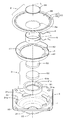
- FIG. 2 is an exploded perspective view of the speaker device
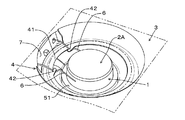
- FIG. 3 is a part around the dust-proof net of the speaker device.
- FIG. 4 is an enlarged cross-sectional view of an outer vibration portion of the speaker device. Note that the concept of “upper and lower” in the following description corresponds to the upper and lower in the drawing of FIG.
- the speaker device includes a voice coil 1, a vibrating body 2 to which the voice coil 1 is connected, a frame 3 that supports the vibrating body 2, and a dustproof net 4 that is an example of an “internal constituent member”. And a magnetic circuit 5.
- the voice coil 1 has a cylindrical shape with the axis L as the central axis, and is formed by winding a coil around a polyimide bobbin.
- the vibrating body 2 is disposed coaxially with the voice coil 1 about the axis L.
- the vibrating body 2 is formed of a thin plate member.
- the vibrating body 2 includes an inner vibrating portion provided inside the voice coil 1 and an outer vibrating portion provided outside the voice coil 1.
- An example of the inner vibrating portion is the center cap 2A.
- the outer vibration part includes a second vibration part and a third vibration part provided outside the second vibration part.
- An example of the second vibrating part is a cone-like vibrating part 2B.
- An example of the third vibrating portion is a curved portion 2C.
- the center cap portion 2A has substantially the same diameter as the voice coil 1, and has a concave shape that is recessed inward of the voice coil 1 in the direction of the axis L.
- the voice coil 1 is connected to the vibrating body 2 at the boundary between the center cap portion 2A and the cone-shaped vibrating portion 2B. That is, the voice coil 1 is fitted in the fitting hole 2a at the center of the cone vibrating portion 2B and fixed with, for example, an adhesive, and the center cap portion 2A is put on the upper end portion of the voice coil 1 and the outer periphery thereof is covered. For example, it is fixed to the cone-shaped vibrating portion 2B and the voice coil 1 with an adhesive.
- the curved portion 2C includes a deformed portion 21 that deforms in response to vibration in the direction of the axis L of the voice coil 1, and a flat plate portion 22 that extends outside the deformed portion 21. It is integrally molded with a resin member together with the cone-shaped vibrating portion 2B.
- Each of the curved portion 2C, the cone-shaped vibrating portion 2B, and the center cap portion 2A is a polyimide member that is an example of a “member having an imide bond”.
- the frame 3 is made of a metal member such as iron, aluminum, magnesium, or a resin member, and has a substantially frustoconical first bulging portion (first outer peripheral side surface) 31 and a smaller diameter than the first bulging portion 31. And a thin cylindrical second bulging portion (second outer peripheral side surface) 32 and a flange portion (diaphragm mounting portion) 33 formed on the outer periphery of the first bulging portion 31.
- a plurality of openings 31 a are formed on the side surface of the first bulging portion 31, and the inner surface 3 a of this side surface is the “inner surface of the frame”.
- the flat plate portion 22 of the bending portion 2 ⁇ / b> C of the vibrating body 2 is fixed to the flange portion 33, and the vibrating body 2 is supported by the frame 3.
- the cone-shaped vibrating portion 2 ⁇ / b> B, the center cap portion 2 ⁇ / b> A, and the voice coil 1 are disposed in the first bulging portion 31.
- the magnetic circuit 5 is disposed in the second bulging portion 32 or attached to the bulging portion 32.
- the dustproof net 4 has a shape that follows the inner method of the first bulging portion 31 of the frame 3, and the dustproof net 4 is accommodated in the first bulging portion 31.
- the dustproof net 4 is obtained by impregnating a cotton net with a phenol resin, and has elasticity and air permeability.
- the inner peripheral portion 41 outside the voice coil 1 of the dustproof net 4 is provided with a protruding portion 42 extending toward the voice coil 1.
- a terminal portion 7 is provided outside the first bulging portion 31 of the frame 3, and the terminal portion 7 and the voice coil 1 are connected by a tinsel wire 6.
- the tinsel wire 6 is connected to the protrusion 42 so as to engage with the protrusion 42 of the dustproof net 4.
- the inner peripheral part 41 outside the voice coil 1 is connected to the tinsel wire 6.
- the dustproof net 4 is an elastic member having elasticity, and the tinsel wire 6 is supported by an elastic member provided in the frame 3.
- the magnetic circuit 5 includes a yoke 51, a magnet 52, and a plate 53.
- the yoke 51 and the plate 53 are made of a magnetic metal such as iron.
- the magnet 52 is a neodymium magnet.
- the magnet 52 may be, for example, a permanent magnet such as ferrite, samarium / cobalt, or alnico.
- the yoke 51 is a thin bottomed cylindrical member in which the cylindrical portion 51a and the bottom portion 51b are integrated, and has a stepped portion 51c protruding inward at the boundary between the cylindrical portion 51a and the bottom portion 51b.
- the magnet 52 and the plate 53 have a disk shape.
- the disk-shaped magnet 52 and the plate 53 are stacked on the bottom 51b of the yoke 51 and arranged in the cylinder 51a. Further, the outer circumferences of the magnet 52 and the plate 53 are respectively installed with a predetermined distance between the inner circumference surface of the cylindrical portion 51 a of the yoke 51. Thereby, a magnetic gap 5 ⁇ / b> G is formed between the inner peripheral end of the plate 22, the upper end of the cylindrical portion 51 a of the yoke 51, and the outer periphery of the plate 53.
- the voice coil 1 is disposed in the magnetic gap 5G of the magnetic circuit 5. When a voice signal is input to the voice coil 1, the voice coil 1 vibrates along the axis L direction and vibrates the vibrating body 2. As a result, the sound radiation direction is parallel to the axis L.
- the vibrating body 2 includes the curved portion 2C having the deformed portion 21 that is deformed in accordance with the vibration of the voice coil 1, and the outer vibrating portion of the vibrating body 2 is formed of at least a resin. Therefore, the deformed portion of the outer vibration portion and other portions other than the deformed portion are integrally formed of resin. Therefore, stable vibration of the voice coil 1 can be realized without a conventional damper that supports the voice coil. Further, the weight is reduced by the amount of no damper, and the sound pressure is improved.
- the tinsel wire 6 is provided in the frame 3 and has elasticity, it is supported by the dustproof net 4 (elastic member), so that the tinsel wire 6 does not resonate and realizes stable vibration of the voice coil 1. be able to.
- a dustproof net 4 extending from the inner surface 3 a of the frame 3 toward the voice coil 1 is provided, and an inner peripheral portion 41 of the dustproof net 4 outside the voice coil 1 is connected to the tinsel wire 6. Yes. Thereby, the stable vibration of the voice coil 1 can be realized without the tinsel wire 6 resonating.
- the inner peripheral portion 41 of the dustproof net 4 is provided with a protruding portion 42 extending toward the voice coil 1, and the tinsel wire 6 is connected to the protruding portion 42.
- the tinsel wire 6 can be flexibly supported while following the vibration of the voice coil 1.
- the magnetic circuit 5 accommodated in the frame 3 is provided, the opening 31a of the frame 3 is covered with a dustproof net 4 having air permeability, and the dustproof net is disposed on the frame 3 side (inner surface 3a side) from the voice coil 1. There are four inner peripheral portions 41. Thereby, dust-proof measures are taken especially for the magnetic circuit 5. Further, the dust-proof net 4 can provide an air resistance against the air in and out of the frame 3 (back space of the vibrating body 2) and the outside, and the vibrating body 2 (and the voice coil 1) vibrates downward too. Can be suppressed.
- the opening 31 a of the frame 3 is covered with a dustproof net 4 having air permeability, and the inner peripheral portion of the dustproof net 4 is disposed between the outer peripheral portion and the inner peripheral portion of the vibrating body 2 in the radial direction of the vibrating body 2. 41 is located. Accordingly, it is possible to prevent the vibrating body 2 that vibrates downward from coming into contact with the dust-proof net 4 and to sufficiently ensure the amplitude of the vibrating body 2.
- step 51c is provided in the yoke 51 of the magnetic circuit 5 at a position facing the lower end of the voice coil 1, even if the voice coil 1 vibrates greatly downward, the lower end of the voice coil 1 Abuts against the stepped portion 51c and the stepped portion 51c serves as a stopper, so that deformation of the vibrating body 2 can be prevented.
- the vibrating body 2 includes a center cap portion 2A having a concave shape at a position facing the magnetic circuit 5.
- the distance h1 from the center cap portion 2A, which is part of the concave-shaped vibrating body 2 to the magnetic circuit 5 is reduced from the lower end portion of the voice coil 1 to the yoke. It is larger than the distance h3 to the step portion 51c.
- the step portion 51 serves as a stopper, and the center cap portion 2A can be prevented from coming into contact with the magnetic circuit 5.
- the vibrating body 2 includes a center cap portion 2A (first vibrating portion) and a concave cone-shaped vibrating portion 2B (second vibrating portion) surrounding the center cap portion 2A. Thereby, the peak dip due to the vibration of the cone-shaped vibrating portion 2B can be reduced.
- FIG. 4 is an enlarged cross-sectional view of the curved portion 2C.
- the deformed portion 21 of the curved portion 2C has a first convex portion 21a and a second convex portion 21b.
- the illustrated arrow P is the radial direction of the vibrating body 2
- the first convex portion 21a has a width W1 in the radial direction
- the second convex portion 21b has a width W2 in the radial direction.
- W1 is a distance from the position where the extended surface of the flat plate portion 22 intersects the cone-shaped vibrating portion 2B to the boundary between the first convex portion 21a and the second convex portion 21b.
- W2 is the distance from the boundary between the first convex portion 21a and the second convex portion 21b to the boundary between the second convex portion 21b and the flat plate portion 22.
- the vibrating body 2 vibrates due to the vibration of the voice coil 1, and the displacement of the vibrating body 2 at this time increases as it becomes closer to the inner peripheral side (voice coil 1 side).
- the radial width W1 of the first convex portion 21a is larger than the radial width W2 of the second convex portion 21b. Therefore, the deformed portion 21 having the first convex portion 21a having the large width W1 on the inner peripheral side can follow the displacement (and stress) due to the vibration of the vibrating body 2 without difficulty, and the cone-shaped vibrating portion 2B (first shape). 2 vibration part) can be flexibly supported by the curved part 2C (third vibration part).
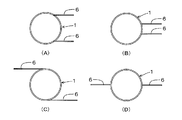
- FIG. 5 is a schematic plan view showing an embodiment and a modification of the voice coil and the tinsel wire.
- FIG. 5A is a positional relationship between the voice coil 1 and the tinsel wire 6 in the embodiment
- FIG. Example 1 and FIG. 5C show Modification Example 2
- FIG. 5D shows Modification Example 3.
- FIG. 5A is a positional relationship between the voice coil 1 and the tinsel wire 6 in the embodiment
- FIG. Example 1 and FIG. 5C show Modification Example 2
- FIG. 5D shows Modification Example 3.
- FIG. 5A is a positional relationship between the voice coil 1 and the tinsel wire 6 in the embodiment
- FIG. Example 1 and FIG. 5C show Modification Example 2
- FIG. 5D shows Modification Example 3.
- two (plural) tinsel wires 6 are drawn from the voice coil 1 in the same direction. This facilitates the routing of the tinsel wire 6 to the terminal portion 7.
- the end portions on the voice coil side of the two (plural) tinsel wires 6 are arranged close to each other and face each other.
- the speaker device (sound generating device) of the embodiment can be used as a normal speaker for reproducing audio such as music, and can also be used as an alarm speaker. It can also be used for speakers that generate sounds emitted by hybrid vehicles.
- the embodiments of the present invention have been described in detail with reference to the drawings. However, the specific configuration is not limited to these embodiments, and the design can be changed without departing from the scope of the present invention. Is included in the present invention.
- the tinsel wire 6 may be covered with a resin member to suppress the occurrence of resonance.
- the embodiments shown in the above drawings can be combined with each other as long as there is no particular contradiction or problem in the purpose and configuration.
- the description content of each figure can become independent embodiment, respectively, and embodiment of this invention is not limited to one embodiment which combined each figure.
Landscapes
- Engineering & Computer Science (AREA)
- Physics & Mathematics (AREA)
- Acoustics & Sound (AREA)
- Signal Processing (AREA)
- Multimedia (AREA)
- Audible-Bandwidth Dynamoelectric Transducers Other Than Pickups (AREA)
Abstract
音発生装置において、ボイスコイルを支持するダンパが無くし、ボイスコイル(1~の安定な振動を実現する。 振動体(2)は、ボイスコイル(1)の振動に伴って変形する変形部分(21)を有する湾曲部(2C)を備える。振動体(2)を湾曲部(2C)と共に樹脂部材で一体成形する。フレーム(3)の内面(3a)からボイスコイル(1)へ向けて延在された防塵ネット(4)を備える。防塵ネット(4)の内周部(41)を突出部(42)にて錦糸線(6)と連結させる。錦糸線(6)が共振せずに、ボイスコイル(1)の安定な振動が実現する。
Description
本発明は、音発生装置に関する。
従来、音発生装置として、例えば特開昭61-1199号公報(特許文献1)に開示されたスピーカ装置がある。この従来のスピーカ装置では、振動板の中心にボイスコイルを接合するとともに、振動板の水平縁をフレームの円筒立縁内に嵌合させて振動板とボイスコイルを保持するものである。
前記特許文献1には振動板とボイスコイルをフレームで保持する構造が開示されているが、振動板とエッジの材質及び詳細構造については記載されていない。振動板とエッジは一般に紙で一体化するものがあるが、このような材質では、ダンパがないと磁気回路にボイスコイルが接触し、うまく振動板を振動させにくいという問題がある。
本発明が解決しようとする課題としては、ダンパを設けずにボイスコイルを安定に振動させるような音発生装置を提供することが一例として挙げられる。
請求項1の音発生装置は、ボイスコイルと、当該ボイスコイルが接続された振動体と、当該振動体を支持するフレームと、を備え、前記振動体は、前記ボイスコイルの振動に伴って変形する変形部分を有する外側振動部を備え、当該振動体の前記外側振動部が樹脂で成形されていることを特徴とする。
請求項17の音発生装置は、ボイスコイルと、当該ボイスコイルが接続された振動体と、当該振動体を支持するフレームと、を備え、前記振動体は、前記ボイスコイルの振動に伴って変形する変形部分を有する外側振動部を備え、該振動体は樹脂で成形されていることで、前記ボイスコイルを支持するダンパをなくしたことを特徴とする。
以下、本発明の一実施形態を説明する。本発明の一実施形態に係る音発生装置は、ボイスコイルと、このボイスコイルが接続された振動体と、振動体を支持するフレームと、を備え、振動体は、ボイスコイルの振動に伴って変形する変形部分を有する振動部を備えている。そして、振動部は樹脂部材で一体成形されている。
樹脂部材はイミド結合を有する部材を用いても構わない。
フレームに設けられ端子部とボイスコイルを接続する錦糸線を備えていても構わない。
複数の錦糸線がボイスコイルから同じ方向に引き出されていても構わない。
複数の錦糸線がボイスコイルから互いに逆方向に引き出されていても構わない。
複数の錦糸線のボイスコイル側の端部は、互いに接近して対向配置されていても構わない。
錦糸線は、フレーム内に設けられた弾性部材で支持されていても構わない。
フレームの内面からボイスコイルへ向けて延在された内部構成部材を備え、ボイスコイルの外側にある内部構成部材の内周部は、錦糸線と連結されていても構わない。
内部構成部材の内周部には、ボイスコイルに向かって延在する突出部を備え、錦糸線は突出部と連結されていても構わない。
フレームに収容される磁気回路を備え、フレームの開口部は、通気性を有する内部構成部材で覆われ、ボイスコイルよりフレーム側に内部構成部材の内周部が有っても構わない。
フレームに支持される磁気回路を備え、フレームの開口部は、通気性を有する内部構成部材で覆われ、振動体の径方向において該振動体の外周部と内周部との間に、内部構成部材の内周部が設けられていても構わない。
ボイスコイルが配置される磁気ギャップを形成する磁石とヨークとを有する磁気回路を備え、ボイスコイルの下端部に対向するヨークの一部には段部が設けられてても構わない。
磁気回路に対面する振動体の一部は、凹状の形状を有していても構わない。
凹状の形状の振動体の一部と磁気回路までの距離が、ボイスコイルの下端部からヨークの段部までの距離より大きくても構わない。
振動体は、第1振動部と、当該第1振動部を囲む凹状の第2振動部と、を備えていても構わない。
振動体は、第2振動部を囲む変形可能な第3振動部を備え、第3振動部は、第1の凸状部とその外周の第2の凸状部とを有し、振動体の径方向において、第1の凸状部の幅が第2の凸状部の幅より大きくても構わない。
本発明の一実施形態に係る音発生装置は、ボイスコイルと、当該ボイスコイルが接続された振動体と、当該振動体を支持するフレームと、を備え、振動体は、ボイスコイルの振動に伴って変形する変形部分を有する外側振動部を備えている。そして、該外側振動部は樹脂で成形されていることで、ボイスコイルを支持するダンパをなくしたことを特徴とする。
図1は本発明の実施例の音発生装置の一例としてのスピーカ装置の平面図及び縦断面図、図2は同スピーカ装置の分解斜視図、図3は同スピーカ装置の防塵ネット回りの一部斜視図、図4は同スピーカ装置の外側振動部の拡大断面図である。なお、以下の説明における「上下」の概念は図1(B)の図面における上下に対応する。
本実施例に係るスピーカ装置は、ボイスコイル1と、このボイスコイル1が接続された振動体2と、この振動体2を支持するフレーム3と、「内部構成部材」の一例である防塵ネット4と、磁気回路5と、を備えている。
ボイスコイル1は軸線Lを中心軸とする円筒状の形状をしており、ポリイミド製のボビンにコイルを巻いたものである。振動体2は軸線Lを中心としてボイスコイル1と同軸に配設されている。また、振動体2は薄板状の部材で形成されている。この振動体2は、ボイスコイル1の内側に設けられた内側振動部、ボイスコイル1より外側に設けられた外側振動部を備えている。内側振動部の一例としてセンターキャップ2Aが挙げられる。外側振動部は、第2振動部、第2振動部の外側に設けられる第3振動部を備えている。第2振動部の一例としてコーン状振動部2Bが挙げられる。第3振動部の一例として湾曲部2Cが挙げられる。
センターキャップ部2Aはボイスコイル1と略同径であり、軸線L方向にボイスコイル1の内側に窪んだ凹状の形状をしている。そして、ボイスコイル1はこのセンターキャップ部2Aとコーン状振動部2Bとの境界部分においてこの振動体2に接続されている。すなわち、ボイスコイル1は、コーン振動部2Bの中心の嵌合孔2a内に嵌合されて例えば接着剤にて固定され、センターキャップ部2Aはボイスコイル1の上端部に被せられてその外周をコーン状振動部2B及びボイスコイル1に例えば接着剤にて固定されている。
湾曲部2Cは、ボイスコイル1の軸線L方向の振動に伴って変形する変形部分21と、この変形部分21の外側に延設された平板部22とを有しており、この湾曲部2Cはコーン状振動部2Bと共に樹脂部材で一体成形されている。この湾曲部2C及びコーン状振動部2Bと、センターキャップ部2Aは、それぞれ「イミド結合を有する部材」の一例であるポリイミド製の部材である。
フレーム3は鉄、アルミニウム、マグネシウムなどの金属部材製又は樹脂部材で形成されており、略円錐台形状の第1膨出部(第1外周側面)31と、この第1膨出部31より小径で薄型円柱状の第2膨出部(第2外周側面)32と、第1膨出部31の外周に形成されたフランジ部(振動板取付部)33とを有している。第1膨出部31の側面には複数の開口部31aが形成されるとともに、この側面の内面3aが「フレームの内面」となっている。そして、振動体2の前記湾曲部2Cの平板部22がフランジ部33に固定され、振動体2はフレーム3に支持されている。これにより、コーン状振動部2B、センターキャップ部2A及びボイスコイル1が第1膨出部31内に配置される。また、磁気回路5は第2膨出部32内に配置されるか膨出部32に取り付けられている。
防塵ネット4はフレーム3の第1膨出部31の内法に倣った形状であり、この防塵ネット4は第1膨出部31内に収容されている。防塵ネット4は綿製のネットにフェノール樹脂を含浸させたものであり、弾性を有するとともに、通気性を有している。
図3に示すように、防塵ネット4のボイスコイル1の外側にある内周部41には、ボイスコイル1に向かって延在する突出部42を備えている。フレーム3の第1膨出部31の外側には端子部7が設けられており、この端子部7とボイスコイル1は錦糸線6によって接続されている。錦糸線6は、防塵ネット4の突出部42に係合するようにこの突出部42と連結されている。これにより、ボイスコイル1の外側にある内周部41は錦糸線6と連結されている。さらに、防塵ネット4は弾性を有する弾性部材であり、錦糸線6はフレーム3内に設けられた弾性部材で支持されている。
磁気回路5は、ヨーク51、磁石52及びプレート53を有している。ヨーク51とプレート53は鉄等の磁性金属で形成されている。磁石52は、ネオジウム系磁石である。なお、この磁石52としては、例えば、フェライト、サマリウム・コバルト系、アルニコ系等の永久磁石でもよい。ヨーク51は、筒部51aと底部51bとを一体にした薄型の有底円筒形状の部材であり、筒部51aと底部51bとの境界に内側に出っ張った段部51cを有している。磁石52とプレート53は円盤状の形状である。
そして、円盤状の磁石52とプレート53は、ヨーク51の底部51b上に積層されて筒部51a内に配置される。また、磁石52とプレート53の外周はヨーク51の筒部51aの内周面との間にそれぞれ所定の距離をもって設置される。これにより、プレート22の内周側端部とヨーク51の筒部51aの上端部とプレート53の外周との間に磁気ギャップ5Gが形成されている。ボイスコイル1は、磁気回路5の磁気ギャップ5G内に配置されている。そして、ボイスコイル1に音声信号が入力されると、ボイスコイル1が軸線L方向に沿って振動し、振動体2を振動させる。これにより、音放射方向は軸線Lと平行な方向となる。
以上のように、振動体2は、ボイスコイル1の振動に伴って変形する変形部分21を有する湾曲部2Cを備え、この振動体2の外側振動部が少なくとも樹脂で成形されている。よって、外側振動部の変形部分及び変形部分以外の他の部分が樹脂で一体に成形されている。したがって、従来のようなボイスコイルを支持するダンパが無くても、ボイスコイル1の安定な振動を実現することができる。また、ダンパが無い分だけ軽量となるとともに、音圧が向上する。
また、錦糸線6は、フレーム3内に設けられ弾性を有するため防塵ネット4(弾性部材)で支持されているので、錦糸線6が共振せずに、ボイスコイル1の安定な振動を実現することができる。
また、フレーム3の内面3aからボイスコイル1へ向けて延在された防塵ネット4を備えており、ボイスコイル1の外側にある防塵ネット4の内周部41は、錦糸線6と連結されている。これにより、錦糸線6が共振せずに、ボイスコイル1の安定な振動を実現することができる。
また、防塵ネット4の内周部41には、ボイスコイル1に向かって延在する突出部42を備えており、錦糸線6は突出部42と連結されている。これにより、錦糸線6をボイスコイル1の振動に追随させつつ、錦糸線6を柔軟に支持することができる。
また、フレーム3に収容される磁気回路5を備え、フレーム3の開口部31aは、通気性を有する防塵ネット4で覆われ、かつ、ボイスコイル1よりフレーム3側(内面3a側)に防塵ネット4の内周部41が有る。これにより、特に磁気回路5に対する防塵対策がとられている。さらに、防塵ネット4により、フレーム3の内部(振動体2の背空間)と外部との空気の出入りに対する空気抵抗を得ることができ、振動体2(及びボイスコイル1)が下方に振動しすぎることを抑止できる。
また、フレーム3の開口部31aは、通気性を有する防塵ネット4で覆われ、振動体2の径方向において振動体2の外周部と内周部との間に、防塵ネット4の内周部41が位置する。これにより、下方に振動した振動体2が防塵ネット4に接触することを防止できるとともに、振動体2の振幅を十分確保することができる。
また、ボイスコイル1の下端部に対向する位置にて、磁気回路5のヨーク51に段部51cが設けられているので、ボイスコイル1が下方に大きく振動しても、このボイスコイル1の下端が段部51cに当接し、段部51cがストッパの役割をするので、振動体2の変形を防止することができる。
また、振動体2は、磁気回路5に対面する位置に、凹状の形状を有するセンターキャップ部2Aを備えている。これに対して、図1(B)に示すように、凹状の形状の振動体2の一部であるセンターキャップ部2Aと、磁気回路5までの距離h1が、ボイスコイル1の下端部からヨークの段部51cまでの距離h3より大きくなっている。これにより、段部51がストッパの役割をして、センターキャップ部2Aが磁気回路5に当接することを防止することができる。
また、振動体2は、センターキャップ部2A(第1振動部)と、このセンターキャップ部2Aを囲む凹状のコーン状振動部2B(第2振動部)とを備えている。これにより、コーン状振動部2Bの振動によるピーク・ディップを低減することができる。
図4は湾曲部2Cの拡大断面図である。湾曲部2Cの変形部分21は、第1の凸状部21aと第2の凸状部21bとを有している。図示の矢印Pは振動体2の径方向であり、第1の凸状部21aは径方向に幅W1を有し、第2の凸状部21bは径方向に幅W2を有している。なお、W1は、平板部22の延長面とコーン状振動部2Bとの交差する位置から、第1の凸状部21aと第2の凸状部21bとの境界までの距離である。また、W2は、第1の凸状部21aと第2の凸状部21bとの境界から、第2の凸状部21bと平板部22の境界までの距離である。
振動体2は、ボイスコイル1の振動により振動するが、このときの振動体2の変位は内周側(ボイスコイル1側)になるにしたがって大きくなる。これに対して、第1の凸状部21aの径方向の幅W1は第2の凸状部21bの径方向の幅W2より大きくなっている。したがって、幅W1の大きな第1の凸状部21aを内周側とした変形部分21は、振動体2の振動による変位(及び応力)に対して無理なく追随でき、コーン状振動部2B(第2振動部)を湾曲部2C(第3振動部)により柔軟に支持することができる。
図5はボイスコイルと錦糸線の実施例と変形例を示す概略平面図であり、図5(A)は実施例におけるボイスコイル1と錦糸線6との位置関係、図5(B)は変形例1、図5(C)は変形例2,図5(D)は変形例3を示す。
図5(A)の実施例の場合と、図5(B)の変形例1の場合は、2本(複数)の錦糸線6がボイスコイル1から同じ方向に引き出されている。これにより、端子部7への錦糸線6の引き回しが容易になる。特に、変形例1の場合は、2本(複数)の錦糸線6のボイスコイル側の端部は、互いに接近して対向配置されている。
図5(C)の変形例2の場合と、図5(D)の変形例3の場合は、2本(複数)の錦糸線6がボイスコイル1から互いに逆方向に引き出されている。この場合、錦糸線6のボイスコイル1側の端部が、ボイスコイル1の中心に対して180°回転の回転対称な位置にあること、又は2本(複数)の錦糸線6が、ボイスコイル1の左右に配置されており、ボイスコイル1及び振動体全体の質量が左右どちらかに偏らないよう対称に配置されていること、などのため、ボイスコイル1の振動への影響がない。
なお、実施例のスピーカ装置(音発生装置)は、音楽等のオーディオ再生用の通常のスピーカとしても使えるし、警報用スピーカとしても使える。また、ハイブリッド自動車が外部に向けて放つ音を発生させるスピーカにも使える。
以上、本発明の実施の形態について図面を参照して詳述してきたが、具体的な構成はこれらの実施の形態に限られるものではなく、本発明の要旨を逸脱しない範囲の設計の変更等があっても本発明に含まれる。例えば、錦糸線6を樹脂部材で覆い、共振の発生を抑止させてもよい。上述の各図で示した実施例は、その目的及び構成等に特に矛盾や問題がない限り、互いの記載内容を組み合わせることが可能である。また、各図の記載内容はそれぞれ独立した実施形態になり得るものであり、本発明の実施形態は各図を組み合わせた一つの実施形態に限定されるものではない。
1 ボイスコイル
2 振動体
2A センターキャップ部(第1振動部,凹状の形状の振動体の一部、内側振動部)
2B コーン状振動部(第2振動部、外側振動部の一部)
2C 湾曲部(第3振動部、外側振動部の一部)
21 変形部分
21a 第1の凸状部
21b 第2の凸状部
22 平板部
3 フレーム
3a 内面
4 防塵ネット(内部構成部材)
5 磁気回路
51 ヨーク
52 磁石
53 プレート
5G 磁気委ギャップ
6 錦糸線
7 端子部
L 軸線
2 振動体
2A センターキャップ部(第1振動部,凹状の形状の振動体の一部、内側振動部)
2B コーン状振動部(第2振動部、外側振動部の一部)
2C 湾曲部(第3振動部、外側振動部の一部)
21 変形部分
21a 第1の凸状部
21b 第2の凸状部
22 平板部
3 フレーム
3a 内面
4 防塵ネット(内部構成部材)
5 磁気回路
51 ヨーク
52 磁石
53 プレート
5G 磁気委ギャップ
6 錦糸線
7 端子部
L 軸線
Claims (17)
- ボイスコイルと、当該ボイスコイルが接続された振動体と、当該振動体を支持するフレームと、を備え、
前記振動体は、前記ボイスコイルの振動に伴って変形する変形部分を有する外側振動部を備え、当該振動体の前記外側振動部が樹脂で成形されていることを特徴とする音発生装置。 - 前記樹脂はイミド結合を有することを特徴とする請求項1に記載の音発生装置。
- 前記フレームに設けられ端子部と前記ボイスコイルを接続する錦糸線を備えることを特徴とする請求項1または2に記載の音発生装置。
- 複数の前記錦糸線が前記ボイスコイルから同じ方向に引き出されていることを特徴とする請求項3に記載の音発生装置。
- 複数の前記錦糸線が前記ボイスコイルから互いに逆方向に引き出されていることを特徴とする請求項3に記載の音発生装置。
- 複数の前記錦糸線の前記ボイスコイル側の端部は、互いに接近して対向配置されていることを特徴とする請求項4に記載の音発生装置。
- 前記錦糸線は、前記フレーム内に設けられた弾性部材で支持されていることを特徴とする請求項3に記載の音発生装置。
- 前記フレームの内面から前記ボイスコイルへ向けて延在された内部構成部材を備え、
前記ボイスコイルの外側にある前記内部構成部材の内周部は、前記錦糸線と連結されていることを特徴とする請求項3乃至6のいずれか一項に記載の音発生装置。 - 前記内部構成部材の内周部には、前記ボイスコイルに向かって延在する突出部を備え、
前記錦糸線は前記突出部と連結されていることを特徴とする請求項8に記載の音発生装置。 - 前記フレームの開口部は、通気性を有する内部構成部材で覆われ、
前記ボイスコイルより前記フレーム側に前記内部構成部材の内周部が有ることを特徴とする請求項1乃至6のいずれか一項に記載の音発生装置。 - 前記フレームの開口部は、通気性を有する内部構成部材で覆われ、
前記振動体の径方向において該振動体の外周部と内周部との間に、前記内部構成部材の内周部があることを特徴とする請求項1乃至6のいずれか一項に記載の音発生装置。 - ヨークを有する磁気回路を備え、
前記ボイスコイルの下端部に対向する前記ヨークの一部に段部が設けられていることを特徴とする請求項1乃至11のいずれか一項に記載の音発生装置。 - 前記磁気回路に対面する前記振動体の一部は、凹状の形状を有することを特徴とする請求項11に記載の音発生装置。
- 前記振動体の一部と前記磁気回路までの距離が、前記ボイスコイルの下端部から前記ヨークの段部までの距離より大きいことを特徴とする請求項13に記載の音発生装置。
- 前記振動体は、第1振動部と、当該第1振動部を囲む凹状の第2振動部と、を備えることを特徴とする請求項1乃至12のいずれか一項に記載の音発生装置。
- 前記振動体は、前記第2振動部を囲む変形可能な第3振動部を備え、前記第3振動部は、第1の凸状部とその外周の第2の凸状部とを有し、前記振動体の径方向において、第1の凸状部の幅が第2の凸状部の幅より大きいことを特徴とする請求項15に記載の音発生装置。
- ボイスコイルと、当該ボイスコイルが接続された振動体と、当該振動体を支持するフレームと、を備え、
前記振動体は、前記ボイスコイルの振動に伴って変形する変形部分を有する外側振動部を備え、該外側振動部は樹脂で成形されていることで、前記ボイスコイルを支持するダンパをなくしたことを特徴とする音発生装置。
Applications Claiming Priority (2)
| Application Number | Priority Date | Filing Date | Title |
|---|---|---|---|
| JP2015073165 | 2015-03-31 | ||
| JP2015-073165 | 2015-03-31 |
Publications (1)
| Publication Number | Publication Date |
|---|---|
| WO2016158285A1 true WO2016158285A1 (ja) | 2016-10-06 |
Family
ID=57007064
Family Applications (1)
| Application Number | Title | Priority Date | Filing Date |
|---|---|---|---|
| PCT/JP2016/057534 Ceased WO2016158285A1 (ja) | 2015-03-31 | 2016-03-10 | 音発生装置 |
Country Status (1)
| Country | Link |
|---|---|
| WO (1) | WO2016158285A1 (ja) |
Citations (5)
| Publication number | Priority date | Publication date | Assignee | Title |
|---|---|---|---|---|
| JP2003348691A (ja) * | 2002-05-28 | 2003-12-05 | Sony Corp | スピーカ装置 |
| JP2004312599A (ja) * | 2003-04-10 | 2004-11-04 | Matsushita Electric Ind Co Ltd | スピーカ |
| JP2007043597A (ja) * | 2005-08-05 | 2007-02-15 | Pioneer Electronic Corp | スピーカー装置用振動板及びスピーカー装置 |
| JP2008277980A (ja) * | 2007-04-26 | 2008-11-13 | Matsushita Electric Ind Co Ltd | スピーカ |
| JP2008278235A (ja) * | 2007-04-27 | 2008-11-13 | Pioneer Electronic Corp | スピーカ用磁気回路及びスピーカ |
-
2016
- 2016-03-10 WO PCT/JP2016/057534 patent/WO2016158285A1/ja not_active Ceased
Patent Citations (5)
| Publication number | Priority date | Publication date | Assignee | Title |
|---|---|---|---|---|
| JP2003348691A (ja) * | 2002-05-28 | 2003-12-05 | Sony Corp | スピーカ装置 |
| JP2004312599A (ja) * | 2003-04-10 | 2004-11-04 | Matsushita Electric Ind Co Ltd | スピーカ |
| JP2007043597A (ja) * | 2005-08-05 | 2007-02-15 | Pioneer Electronic Corp | スピーカー装置用振動板及びスピーカー装置 |
| JP2008277980A (ja) * | 2007-04-26 | 2008-11-13 | Matsushita Electric Ind Co Ltd | スピーカ |
| JP2008278235A (ja) * | 2007-04-27 | 2008-11-13 | Pioneer Electronic Corp | スピーカ用磁気回路及びスピーカ |
Similar Documents
| Publication | Publication Date | Title |
|---|---|---|
| US8520885B2 (en) | Composite speaker | |
| JP6353078B2 (ja) | スピーカ装置 | |
| JPWO2009016743A1 (ja) | スピーカ装置 | |
| US9681233B2 (en) | Loudspeaker diaphragm | |
| KR101584651B1 (ko) | 슬림형 스피커 및 그의 제조 방법 | |
| US9485582B2 (en) | Speaker | |
| US9510087B2 (en) | Acoustic device | |
| US20120177244A1 (en) | Speaker | |
| JP2018157589A (ja) | スピーカ装置 | |
| KR101485688B1 (ko) | 가동자석형 변환기 | |
| JP2015170881A (ja) | スピーカー振動板及び動電型スピーカー | |
| KR101595175B1 (ko) | 이중 구동부를 갖는 마이크로 스피커 | |
| KR200454024Y1 (ko) | 다기능 마이크로 스피커 | |
| US11057713B2 (en) | Vibratable element for loudspeaker use and loudspeaker device | |
| JP6253101B2 (ja) | 動電型電気音響変換器、及びその振動板、並びに動電型電気音響変換器の製造方法 | |
| JP2009159009A (ja) | スピーカ | |
| JP7624272B2 (ja) | スピーカー装置 | |
| WO2016158285A1 (ja) | 音発生装置 | |
| CN219181668U (zh) | 高性能薄型扬声器 | |
| KR101345335B1 (ko) | 스피커 | |
| KR101722527B1 (ko) | 박형 스피커 | |
| KR101627527B1 (ko) | 박형 스피커 | |
| KR102434194B1 (ko) | 스피커 | |
| JP2016072914A (ja) | 動電型スピーカー | |
| JP5781951B2 (ja) | 薄型スピーカ |
Legal Events
| Date | Code | Title | Description |
|---|---|---|---|
| 121 | Ep: the epo has been informed by wipo that ep was designated in this application |
Ref document number: 16772169 Country of ref document: EP Kind code of ref document: A1 |
|
| NENP | Non-entry into the national phase |
Ref country code: DE |
|
| 122 | Ep: pct application non-entry in european phase |
Ref document number: 16772169 Country of ref document: EP Kind code of ref document: A1 |
|
| NENP | Non-entry into the national phase |
Ref country code: JP |