WO2016158091A1 - 光ファイバ装置 - Google Patents
光ファイバ装置 Download PDFInfo
- Publication number
- WO2016158091A1 WO2016158091A1 PCT/JP2016/055171 JP2016055171W WO2016158091A1 WO 2016158091 A1 WO2016158091 A1 WO 2016158091A1 JP 2016055171 W JP2016055171 W JP 2016055171W WO 2016158091 A1 WO2016158091 A1 WO 2016158091A1
- Authority
- WO
- WIPO (PCT)
- Prior art keywords
- optical fiber
- light
- incident
- wavelength
- light source
- Prior art date
- Legal status (The legal status is an assumption and is not a legal conclusion. Google has not performed a legal analysis and makes no representation as to the accuracy of the status listed.)
- Ceased
Links
Images





Classifications
-
- G—PHYSICS
- G02—OPTICS
- G02B—OPTICAL ELEMENTS, SYSTEMS OR APPARATUS
- G02B6/00—Light guides; Structural details of arrangements comprising light guides and other optical elements, e.g. couplings
-
- G—PHYSICS
- G02—OPTICS
- G02B—OPTICAL ELEMENTS, SYSTEMS OR APPARATUS
- G02B6/00—Light guides; Structural details of arrangements comprising light guides and other optical elements, e.g. couplings
- G02B6/24—Coupling light guides
- G02B6/42—Coupling light guides with opto-electronic elements
-
- H—ELECTRICITY
- H01—ELECTRIC ELEMENTS
- H01S—DEVICES USING THE PROCESS OF LIGHT AMPLIFICATION BY STIMULATED EMISSION OF RADIATION [LASER] TO AMPLIFY OR GENERATE LIGHT; DEVICES USING STIMULATED EMISSION OF ELECTROMAGNETIC RADIATION IN WAVE RANGES OTHER THAN OPTICAL
- H01S5/00—Semiconductor lasers
- H01S5/02—Structural details or components not essential to laser action
Definitions
- the present invention relates to an optical fiber device, and more particularly to an optical fiber device that utilizes leaked light from the side surface of the optical fiber.
- Patent Document 1 there is a technique of using leakage light from the side surface of an optical fiber for illumination or the like (for example, see Patent Document 1).
- An optical fiber capable of leaking light from the side face is described in Patent Document 2, for example.
- Patent Document 2 in order to reduce the optical loss, it is disclosed that the brightness is kept uniform by making light enter the optical fiber as straight as possible.
- the optical fiber When light travels through the optical fiber, light loss occurs as it travels in the optical fiber axial direction. As a result, when leakage light from the side surface of the optical fiber is used for illumination or the like, the brightness of the fiber side surface differs between a region near the end surface on the incident side of the optical fiber and a region away from the end surface.
- an object of the present invention is to provide an optical fiber device that suppresses a loss of light traveling in an optical fiber as compared with a conventional device.
- An optical fiber device includes: A light source unit for generating laser light; An optical element on which light emitted from the light source unit is incident; A first optical fiber that receives light emitted from the optical element and can leak light from a side surface; The incident angle distribution indicated by the light incident on the incident end face of the first optical fiber is wider than the incident angle distribution indicated by the light incident on the incident end face of the optical element.
- the inventors' diligent research has found that the loss of light in the optical fiber is affected by the incident angle of light at the end face on the incident side of the optical fiber.
- a case where light is incident with a small incident angle on the incident side end face of the optical fiber is compared with a case where light is incident with a large incident angle.
- the number of reflections repeated in the optical fiber is greater in the latter than in the former.
- an optical fiber device that uses leakage light from the side surface of an optical fiber when light incident from the end surface on the incident side of the optical fiber travels to the side surface of the optical fiber, Light passes through the cladding and is emitted to the outside. Also, some is lost as heat. For this reason, as the number of reflections increases, the intensity decreases as the light travels in the optical axis direction of the optical fiber.
- the optical fiber has an elongated shape and has a property of being easily bent. For this reason, in particular, when leaking light from the side surface is used for illumination purposes, the optical fiber can be twisted according to the shape of the place to be illuminated. In other words, it is practically difficult to arrange the optical fiber on a straight line without bending, and it is usually used in a bent state. Moreover, it has the property that the arrangement
- the angle of light incident on the side surface of the optical fiber changes at the bent portion. For this reason, even for light with a small incident angle at the end surface on the incident side of the optical fiber, the incident angle with respect to the side surface of the optical fiber changes at the curved portion of the optical fiber, and the reflection frequency on the side surface of the optical fiber thereafter increases. It is possible to increase. In this case, as described above, the loss in the optical fiber increases.
- the incident angle distribution of the light at the end face on the incident side of the first optical fiber is widened by making the light incident on the optical fiber (first optical fiber) through the optical element. That is, the light incident on the incident side end face of the first optical fiber has many incident angle components.
- the angle of light incident on the side surface of the first optical fiber changes after passing through the bent portion.
- the light incident on the first optical fiber includes light having many angular components, and therefore, after passing through the bent portion, the reflection on the side surface While there is light that increases in frequency, there is also light that decreases in frequency of reflection. In other words, even when the first optical fiber is used in a curved state, loss of light is suppressed, and sufficient light intensity is maintained even at a position away from the end surface on the incident side of the first optical fiber in the optical axis direction. can do.
- the optical element may be composed of a second optical fiber for guiding light. Once the laser light is incident on the second optical fiber, the light travels while being repeatedly reflected in the second optical fiber and is emitted to the first optical fiber. Since light of many angular components is mixed in the second optical fiber, light having a wide angular distribution with respect to the first optical fiber can be obtained by making the light emitted from the second optical fiber enter the first optical fiber. Can be incident.
- the second optical fiber may be curved at some locations.
- the second optical fiber may be arranged so that the end surface on the emission side of the second optical fiber is not parallel to the end surface on the incident side of the first optical fiber.
- the optical element is not limited to an optical fiber as long as it can expand the angular distribution of light, and for example, a diffusion plate or the like can be used.
- the optical fiber device has In the case where the wavelength is 380 nm or more and less than 500 nm is a blue region, the wavelength 500 nm or more and less than 580 nm is a green region, and the wavelength 580 nm or more and less than 700 nm is a red region,
- the light source unit may include a semiconductor laser element that generates laser light having a wavelength longer than a specific wavelength in which the attenuation constant at the wavelength of light traveling in the first optical fiber is maximum in the same color region. I do not care.
- FIG. 1A is a graph showing an example of loss characteristics of a first optical fiber used as an optical fiber for side light emission.
- the horizontal axis indicates the wavelength of light to be transmitted through the optical fiber, and the vertical axis indicates the attenuation constant.
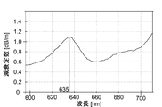
- FIG. 1B is an enlarged view of the wavelength range of 600 nm to 700 nm in FIG. 1A.
- the ease of loss (attenuation constant) in an optical fiber varies depending on the wavelength of light.
- the attenuation constant shows a maximum value near the wavelength of 635 nm.
- the wavelength 635 nm corresponds to the specific wavelength.
- an optical fiber having loss characteristics as shown in FIG. 1A it is assumed that laser light having a wavelength of 635 nm, for example, is used as light in the red region.
- FIG. 1B since the attenuation constant for light with a wavelength of 635 nm is high, compared with the case where light having a shorter wavelength (for example, 625 nm) or longer wavelength (for example, light having a wavelength of 645 nm) is used.
- the loss in the first optical fiber increases. Therefore, in the first optical fiber having the characteristics shown in FIG. 1A, in order to maintain the emission intensity as much as possible in the fiber axis direction, light having a shorter wavelength or longer wavelength is used instead of the specific wavelength of 635 nm. It can be seen that it is preferable to use.
- the semiconductor laser element continues to emit light, the temperature rises due to deterioration or the like, and accordingly, the oscillation wavelength shifts to the long wavelength side.
- the wavelength of the light emitted from the light source unit is shifted to the long wavelength side with time, and as a result, the first optical fiber is Will increase the damping constant.
- the wavelength of light emitted from the light source unit with time is shifted to the long wavelength side by using light having a wavelength longer than 635 nm. Even so, the attenuation constant in the first optical fiber tends to decrease. Thereby, the emission intensity can be maintained as much as possible in the optical axis direction in the first optical fiber.
- the first optical fiber having an attenuation characteristic as shown in FIG. 1A and FIG. 1B has been taken as an example, but in general, in the case of using the first optical fiber having a maximum value in the attenuation characteristic, Similarly, the same effect is realized by using light having a wavelength longer than the specific wavelength exhibiting the maximum value. However, even though the light has a longer wavelength than the specific wavelength, for example, when the light in the red region is used, although the specific wavelength is in the blue region, the emission color has changed significantly in the first place. End up. Therefore, by using light having a wavelength longer than the specific wavelength in the same color region, the emission intensity in the first optical fiber is maintained at the same level while maintaining the emission intensity as much as possible in the fiber axis direction. be able to.
- the light source unit has a wavelength longer than a specific wavelength at which the attenuation constant at the wavelength of the light traveling in the first optical fiber is a maximum in the same color region, and the attenuation constant is a minimum.
- a semiconductor laser element that generates laser light having a shorter wavelength than another specific wavelength shown may be included.
- the light source unit may generate two or more different wavelengths of laser light. According to said structure, since the loss in a 1st optical fiber can be suppressed irrespective of a wavelength, the change of the color of the fiber axial direction in a 1st optical fiber can be suppressed.
- optical fiber device of the present invention loss of light traveling in the optical fiber can be suppressed as compared with the conventional device.
- FIG. 1 It is a graph which shows an example of the loss characteristic of a 1st optical fiber. It is the graph which expanded a part of Drawing 1A. It is an example of the block diagram which shows typically the optical fiber device of 1st embodiment. It is a graph for demonstrating that the angle distribution of light spreads by passing a 2nd optical fiber. It is an example of the block diagram which shows typically the optical fiber device of 1st embodiment. It is drawing which shows typically the structure of the optical fiber apparatus used for verification. It is a graph which shows angle distribution of the light which injects into the end surface of the incident side of a 1st optical fiber in each case of Example 2, Example 3, and the comparative example 1.
- FIG. 1 shows an example of the loss characteristic of a 1st optical fiber. It is the graph which expanded a part of Drawing 1A. It is an example of the block diagram which shows typically the optical fiber device of 1st embodiment. It is a graph for demonstrating that the angle distribution of light spreads by passing a 2nd optical fiber. It is an example of
- FIG. 2 It is the graph which evaluated the loss in a 1st optical fiber in each case of Example 2, Example 3, and the comparative example 1.
- FIG. 2 It is the graph which evaluated the loss in a 1st optical fiber in each case of Example 2, Example 3, and the comparative example 1.
- FIG. It is a graph which shows an example of the loss characteristic of a 1st optical fiber. It is a graph which shows an example of the loss characteristic of a 1st optical fiber.
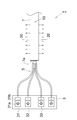
- FIG. 2 is an example of a block diagram schematically showing the optical fiber device of the first embodiment.
- the optical fiber device 1 includes a light source unit 3 including a plurality of light sources (31, 32, 33,...), A light guide optical fiber 5 into which light emitted from the light source unit 3 is incident, and an optical fiber 5. And a side-emitting optical fiber 7 into which the propagated light is incident.
- the optical fiber 7 is referred to as “first optical fiber 7”
- the optical fiber 5 is referred to as “second optical fiber 5”.
- FIG. 2 illustrates the case where the second optical fiber 5 is a bundle fiber, it is not always necessary to be a bundle fiber.
- the light source 31 includes a semiconductor laser element 31a that emits light of a certain wavelength, and a collimator lens 31b that converts the light emitted from the semiconductor laser element 31a into parallel light.
- Laser light emitted from each semiconductor laser element (31a,%) Is converted into parallel light via a corresponding collimator lens (31b,%) And then incident on the second optical fiber 5.
- the laser light emitted from the semiconductor laser element (31a,%) With high efficiency such as the distance between the semiconductor laser element (31a,%) And the end face on the incident side of the second optical fiber 5 is close.
- the collimating lens (31b,...) Need not necessarily be provided.
- the wavelengths of light emitted from the light sources (31, 32, 33,...) are the same.
- this wavelength is 640 nm.
- the case where light of a plurality of wavelengths is emitted from the light source unit 3 will be described later.
- the light incident on the first optical fiber 7 via the second optical fiber 5 is taken out as leaked light 20 from the side surface of the first optical fiber 7 and used for illumination, for example.
- the optical axis of the first optical fiber 7 is denoted by reference numeral 10.
- the light emitted from the light source unit 3 is once incident on the first optical fiber 7 via the second optical fiber 5.
- the distribution of incident angles of light incident on the end surface 7a is expanded.
- the angular distribution can be further expanded by bending the second optical fiber 5 on a part of the first optical fiber 7 instead of arranging it on a straight line.
- FIG. 3 is a simulation result for explaining that the angular distribution of light is expanded by passing through the second optical fiber 5.
- the vertical axis and the horizontal axis indicate the direction cosine of the direction vector of the incident light incident on the end face 7 a of the first optical fiber 7.
- light and dark indicate relative values of the light emission intensity for each incident angle, and regions having higher radiation intensity values are displayed as whitish on the drawing.
- two orthogonal axes on the plane including the end face 7a are taken as an X axis and a Y axis, respectively.
- the direction of the optical axis 10 of the first optical fiber 7, that is, the direction orthogonal to the plane (XY plane) formed by the X axis and the Y axis is defined as the Z axis direction.
- Example 1 is a graph showing the angular distribution of light emitted from the second optical fiber 5 when laser light is incident on the second optical fiber 5 from one light source 31 in the light source unit 3.
- Reference Example 1 corresponds to a case where light emitted from the light source unit 3 is directly incident on the first optical fiber 7 without passing through the second optical fiber 5.
- Reference Example 2 corresponds to the case where a light guiding glass rod is disposed in place of the second optical fiber 5 in the configuration of Example 1.
- the second optical fiber 5 is softer and easier to bend than the light guiding glass rod.
- the optical axis of the second optical fiber 5 extends from the end surface on the incident side of the second optical fiber 5 to the end surface on the emission side, and the incident side of the first optical fiber 7. It is difficult to match with the direction orthogonal to the end face 7a.
- the distribution of the radiation intensity spreads concentrically, and the effect of expanding the angular distribution is obtained as compared with the configuration of Reference Example 1, that is, when no glass rod is arranged.
- the intensity of light of an angle component other than the vicinity of the incident angle indicating the peak is weak.
- the light which injects into the 1st optical fiber 7 shows various incident angles. In other words, light having a wide angular distribution can be incident on the first optical fiber 7 by causing the light emitted from the light source unit 3 to enter the first optical fiber 7 once through the second optical fiber 5.
- the second optical fiber 5 is arranged in a partially bent state, so that the incident angle on the side surface of the second optical fiber 5 changes at this location, and as a result, light having many angle components is emitted. It is inferred that it was generated.
- FIG. 4 corresponds to a configuration in which the incident-side end surface 7a of the first optical fiber 7 is inclined by an angle ⁇ with respect to the emission-side end surface of the second optical fiber 5 from the configuration of FIG.
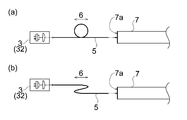
- FIG. 5 is a drawing schematically showing the configuration of the optical fiber device used for the verification, wherein (a) corresponds to a schematic view when viewed from above, and (b) is a schematic when viewed from the side. Corresponds to the figure.
- the light source unit 3 is simulated by one light source 32, and the light emitted from the light source unit 3 is transmitted through the second optical fiber 5 to the first optical fiber. 7 was incident.
- Example 2 the emission-side end face of the second optical fiber 5 and the incident-side end face 7a of the first optical fiber 7 were made parallel.
- Example 3 as shown in FIG. 4, the end surface on the emission side of the second optical fiber 5 and the end surface 7 a on the incident side of the first optical fiber 7 are arranged so as to be inclined by an angle ⁇ . More specifically, in Example 2, the angle ⁇ was 0 °, and in Example 3, the angle ⁇ was 10 °.
- Example 2 and Example 3 the incident angle to the side surface of the second optical fiber 5 was changed by bending the second optical fiber 5 in a spiral at one place (region 6). More specifically, as the second optical fiber 5, an optical fiber having a total length of 5 m, a core diameter of 800 ⁇ m, and an NA of 0.22 is used, the bending radius in the region 6 is 160 mm, and the length before and after the region 6 is Each was 2000 mm. The interval between the second optical fibers 5 in the region 6 was 5 mm.
- the light source unit 3 is simulated by one light source 32, and light emitted from the light source unit 3 is directly incident on the first optical fiber 7 without passing through the second optical fiber 5. It was.
- FIG. 6 is a graph showing the angular distribution of light incident on the end surface 7a on the incident side of the first optical fiber 7 in each of Example 2, Example 3, and Comparative Example 1.
- the horizontal axis indicates the incident angle of light with respect to the end face 7a of the first optical fiber 7, and the vertical axis indicates the relative value of the light emission intensity for each incident angle. Yes.
- Example 2 and Example 3 in which the light emitted from the light source unit 3 through the second optical fiber 5 is incident on the first optical fiber 7, the first optical fiber is compared with the first comparative example. It can be seen that the light incident on 7 includes light having many angle components. Furthermore, the angular distribution of light incident on the first optical fiber 7 is wider in the third embodiment than in the second embodiment. From this, the angle of the light incident on the first optical fiber 7 can be obtained by disposing the end surface 7a on the incident side of the first optical fiber 7 non-parallel to the end surface on the emission side of the second optical fiber 5. It can be seen that the effect of further expanding the distribution can be obtained.
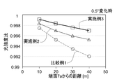
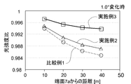
- FIG. 7 and 8 are graphs in which loss in the first optical fiber 7 is evaluated in each case of Example 2, Example 3, and Comparative Example 1.
- FIG. 7 and 8 the horizontal axis indicates the distance in the direction of the optical axis 10 from the incident-side end surface 7a in the first optical fiber 7, and the vertical axis indicates the light intensity ratio. The value on the vertical axis will be described.
- first state that is, in the state showing the angular distribution shown in FIG.
- first state the luminance values of leaked light from four side surfaces that are 10 m, 20 m, 30 m, and 40 m away from the end surface 7 a in the direction of the optical axis 10 are calculated.
- second state the embodiment is similarly performed.
- the luminance value of the leaked light from the four side surfaces is calculated.
- the relative value of the luminance value at each measurement location in the second state with respect to the first state is calculated as the “light intensity ratio”.
- the loss in the first optical fiber 7 increases as the number of reflections on the side surface of the first optical fiber 7 increases. Therefore, it is assumed that the loss (attenuation rate) per unit length in the direction of the optical axis 10 is proportional to the number of reflections per unit length in the direction of the optical axis 10 on the side surface of the first fiber 7.
- the loss in one reflection on the side surface of the first optical fiber 7 was 0.2%. This is a numerical value derived from experimental values when an optical fiber with NA of 0.65 is used as the first optical fiber 7.
- the light propagation angle in the first optical fiber 7 changed by 0.5 ° (FIG. 7) and 1 ° (FIG. 8).
- the four-point measurement is performed when the second state angle distribution is derived from the angle distribution shown in FIG. 6 and light having the newly derived angle distribution is incident on the first optical fiber 7.
- the luminance value at the point was calculated for each of Example 2, Example 3, and Comparative Example 1. Then, a relative value with the luminance value in the first state was calculated and graphed.
- the brightness value is significantly larger in the case of Comparative Example 1 than in Example 2 and Example 3 after the handling state of the first optical fiber 7 is changed. It can be seen that it has dropped.
- the second optical fiber 5, the emission-side end face, and the incident-side end face 7 a of the first optical fiber 7 are arranged non-parallel so that the light intensity is further reduced as compared with the second embodiment. It can be seen that is suppressed.
- the first optical fiber 7 is an optical fiber for side light emission, and it is assumed that the leaked light 20 is used for applications such as illumination. For this reason, it is assumed that the arrangement mode of the first optical fiber 7 is appropriately changed according to the place to be illuminated. In addition, since the first optical fiber 7 itself is soft and easy to bend, it is conceivable that the manner of arrangement easily changes.
- the wavelength of light emitted from the light source unit 3 is set to be longer than the wavelength (specific wavelength) at which the attenuation constant exhibits a maximum value on the curve indicating the loss characteristics of the first optical fiber 7.
- the first optical fiber 7 exhibits attenuation characteristics as shown in FIGS. 1A and 1B.
- the attenuation constant shows a maximum value near the wavelength of 635 nm.
- light having a wavelength longer than 635 nm is emitted from the light source unit 3.
- 1A and 1B are examples of attenuation characteristics of a side-emitting optical fiber manufactured by 3M.
- the semiconductor laser elements (31a,%) are often feedback controlled so as to reach a predetermined temperature. However, it is possible to detect the temperature of the light emitting point itself of the semiconductor laser elements (31a,). Since it is difficult, usually, a temperature at a position slightly away from the light emitting point is detected, and feedback control is performed based on this temperature. Therefore, it is difficult to keep the temperature of the semiconductor laser elements (31a,%) Constant, and the oscillation wavelength is shifted to the long wavelength side over time.
- the light source unit 3 emits light having a wavelength longer than the specific wavelength exhibiting the maximum value, so that the light emitted from the light source unit 3 is shifted to the long wavelength side over time.
- the damping constant tends to decrease. Thereby, the phenomenon that the emitted light intensity in the 1st optical fiber 7 falls with time is suppressed.
- the light source unit 3 emits light having a wavelength longer than the specific wavelength indicating the maximum value and shorter than the wavelength indicating the minimum value.
- the vicinity of 660 nm is the minimum value of the attenuation characteristic.
- the light source unit 3 is preferably configured to emit light having a wavelength longer than 635 nm and shorter than 660 nm.
- FIG. 9A and 9B are graphs showing attenuation characteristics of the first optical fiber 7 made of a material different from that shown in FIG. 1A.
- FIG. 9A is a graph showing the attenuation characteristic of an optical fiber manufactured by Innovative Lighting
- FIG. 9B is a graph showing the attenuation characteristic of an optical fiber manufactured by Mitsubishi Rayon.
- These optical fibers also have a maximum value in attenuation characteristics. More specifically, the example of FIG. 9A has a maximum value at a wavelength near 625 nm, and the example of FIG. 9B has a maximum value at a wavelength near 622 nm.
- the light source unit 3 is made to emit light having a wavelength longer than the above-described wavelengths (625 nm, 622 nm), for example, light having a wavelength of 635 nm.
- emits By setting it as the structure which inject
- light of a plurality of wavelengths may be emitted from the light source unit 3.
- the light source unit 3 may emit light of each color region. Absent.
- the loss in the first optical fiber 7 is reduced, the light emission color changes as the light travels in the first optical fiber 7 or the light emission intensity decreases. Can be suppressed.
- the light source 3 can emit light having a wavelength longer than the specific wavelength in the same color region.
- the loss in the first optical fiber 7 tends to decrease even if the wavelength of the light emitted from the light emitting unit 3 is shifted to the long wavelength side over time. As a result, the change in emission color in the first optical fiber 7 is suppressed.
- an optical fiber having attenuation characteristics shown in FIG. 9B has a maximum value in the vicinity of a wavelength of 545 nm in the green region (wavelength of 500 nm or more and less than 580 nm), and a wavelength in the red region (wavelength of 580 nm or more and less than 700 nm). It has a maximum value in the vicinity of 622 nm.
- the light source unit 3 included in the optical fiber device 1 emits light having a wavelength longer than 545 nm, for example, light having a wavelength of 560 nm, as light in the green region.
- the light in the region As the light in the region, light having a wavelength longer than 622 nm, for example, light having a wavelength of 640 nm is emitted. Thereby, the phenomenon that the luminescent color in the 1st optical fiber 7 changes with time is suppressed.
- the first optical fiber 7 for example, an optical fiber having a core made of an acrylic resin can be used, but the material is not limited to this.
- the second optical fiber 5 is preferably configured to have a smaller diameter than the first optical fiber 7. Thereby, the amount of light leakage can be minimized while the light emitted from the second optical fiber 5 is incident on the first optical fiber 7.
- the angle ⁇ between them is set to the first optical fiber. It is preferable that the NA is 7 or less. Thereby, the amount of light leakage can be minimized while the light emitted from the second optical fiber 5 is incident on the first optical fiber 7.
- the light source unit 3 includes the semiconductor laser element (31a,...) Has been described. However, not only the semiconductor laser element but also an element that generates laser light can be employed. .
- Optical fiber device 3 Light source unit 5: Second optical fiber 6: Curved portion of the second optical fiber 7: First optical fiber 7a: End face on the incident side of the first optical fiber 10: Optical axis of the first optical fiber 20: Leakage light 31, 32, 33: Light source 31a: Semiconductor laser element 31b: Collimating lens
Landscapes
- Physics & Mathematics (AREA)
- General Physics & Mathematics (AREA)
- Optics & Photonics (AREA)
- Condensed Matter Physics & Semiconductors (AREA)
- Electromagnetism (AREA)
- Optical Couplings Of Light Guides (AREA)
- Light Guides In General And Applications Therefor (AREA)
- Semiconductor Lasers (AREA)
Abstract
光ファイバ内を進行する光の損失を抑制した光ファイバ装置を実現する。 光ファイバ装置は、レーザ光を生成する光源部と、光源部から射出された光が入射される光学素子と、光学素子から射出された光が入射され、側面から漏光させることのできる第一光ファイバとを備える。第一光ファイバの入射側の端面に入射される光が示す入射角度の分布が、前記光学素子の入射側の端面に入射される光が示す入射角度の分布よりも広い。
Description
本発明は光ファイバ装置に関し、特に光ファイバ側面からの漏れ光を利用する光ファイバ装置に関する。
従来、光ファイバの側面からの漏れ光を照明等に利用する技術が存在する(例えば、特許文献1参照)。また、このように側面から光を漏れさせることのできる光ファイバについては、例えば特許文献2等に記載がある。この特許文献2によれば、光損失を小さくするために、光ファイバに対してできるだけまっすぐ光を入射することで明るさを均一に保つことが開示されている。
光ファイバ内を光が進行すると、光ファイバ軸方向に進むに連れて光の損失が発生する。この結果、光ファイバの側面からの漏れ光を照明等の用途に利用した場合、光ファイバの入射側の端面に近い領域と、前記端面から離れた領域とではファイバ側面の輝度が異なってしまう。
本発明は、上記の課題に鑑み、従来の装置と比較して、光ファイバ内を進行する光の損失を抑制した光ファイバ装置を提供することを目的とする。
本発明に係る光ファイバ装置は、
レーザ光を生成する光源部と、
前記光源部から射出された光が入射される光学素子と、
前記光学素子から射出された光が入射され、側面から漏光させることのできる第一光ファイバとを備え、
前記第一光ファイバの入射側の端面に入射される光が示す入射角度の分布が、前記光学素子の入射側の端面に入射される光が示す入射角度の分布よりも広いことを特徴とする。
レーザ光を生成する光源部と、
前記光源部から射出された光が入射される光学素子と、
前記光学素子から射出された光が入射され、側面から漏光させることのできる第一光ファイバとを備え、
前記第一光ファイバの入射側の端面に入射される光が示す入射角度の分布が、前記光学素子の入射側の端面に入射される光が示す入射角度の分布よりも広いことを特徴とする。
ここで、「端面に入射される光が示す入射角度の分布が広い」とは、当該端面に入射される光のうち、所定値以上の放射強度を示す光が示す入射角度θの範囲が広いことを意味する。
本発明者らの鋭意研究により、光ファイバ内における光の損失は、光ファイバの入射側の端面における光の入射角度の影響を受けることを見出した。
例として、光ファイバの入射側の端面における入射角度を小さくして光を入射させた場合と、入射角度を大きくして光を入射させた場合とを比較する。光ファイバ内を、光ファイバの光軸方向に同一の距離だけ光を進行させると、光ファイバ内で繰り返される反射の回数は、前者よりも後者の方が多い。光ファイバの側面からの漏れ光を利用する光ファイバ装置においては、光ファイバの入射側の端面から入射された光が、光ファイバの側面まで進行すると、当該側面で反射されると共に、一部の光がクラッドを通過して外部に放出される。また、一部は熱として損失される。このため、反射の回数が多い光ほど、光ファイバの光軸方向に進むに連れて、強度は低下する。
ところで、光ファイバは細長い形状を有しており、容易に曲がりやすい性質を有する。このため、特に、側面からの漏れ光を照明用途等に利用する場合においては、照明させたい場所の形状に応じて光ファイバを這わせることができる。つまり、光ファイバを曲げることなく直線上に配置することは現実的には難しく、またむしろ曲げた状態で利用されるのが通常である。また、周囲の環境に応じて光ファイバの配置態様が容易に変化しやすいという性質を有している。
しかし、このように光ファイバが曲げられて利用される場合、当該曲がっている箇所において、光ファイバの側面に入射される光の角度は変化する。このため、光ファイバの入射側の端面における入射角度の小さい光であっても、光ファイバの湾曲箇所において、光ファイバの側面に対する入射角度が変化し、その後に光ファイバの側面での反射頻度が増加することが考えられる。この場合、上述したように、光ファイバ内での損失が増大する。
上記の構成によれば、光学素子を介して光ファイバ(第一光ファイバ)に光を入射することで、第一光ファイバの入射側の端面における光の入射角度分布を広げている。つまり、第一光ファイバの入射側の端面に入射される光は、多くの入射角度成分を有する。ここで、第一光ファイバが曲げられている場合、当該曲がっている箇所を通過した後に、第一光ファイバの側面に入射される光の角度が変化する。しかし、上記の構成によれば、第一光ファイバに入射される光には多くの角度成分を有する光が含まれているため、当該曲がっている箇所を通過した後において、側面での反射の頻度が増加する光がある一方で、反射の頻度が減少する光も存在する。つまり、第一光ファイバが湾曲した状態で利用されていても、光の損失が抑制され、第一光ファイバの入射側の端面から光軸方向に離れた位置においても、十分な光強度を維持することができる。
一方、第一光ファイバに湾曲箇所がほとんど存在していない場合であっても、多くの角度成分の光が入射される構成であるため、反射頻度が高い光と反射頻度が低い光を混在させることができる。これにより、第一光ファイバの入射側の端面に近い位置と、入射側の端面からファイバ軸方向に離れた位置とで、ほぼ同程度の光強度を維持することができる。
前記光学素子は、導光用の第二光ファイバで構成されるものとしても構わない。レーザ光をいったん第二光ファイバに入射させることで、第二光ファイバ内において反射を繰り返しながら光が進行して第一光ファイバに射出される。第二光ファイバ内において多くの角度成分の光が混ざり合うため、この第二光ファイバから射出される光を第一光ファイバに入射させることで、第一光ファイバに対して角度分布の広い光を入射させることができる。
第二光ファイバ内において角度分布を更に拡げる観点からは、第二光ファイバを一部の箇所において湾曲させるものとしても構わない。
また、第二光ファイバの射出側の端面を、第一光ファイバの入射側の端面に対して非平行となるように、第二光ファイバを配置するものとしても構わない。このようにすることで、第一光ファイバの入射側の端面に入射される光の角度分布を更に拡げることができる。
なお、前記光学素子は、光の角度分布を拡げることのできる素子であれば、光ファイバに限定されず、例えば拡散板等を用いることもできる。
前記光ファイバ装置は、上記の構成に加えて、
波長380nm以上500nm未満を青色領域、波長500nm以上580nm未満を緑色領域、波長580nm以上700nm未満を赤色領域とした場合において、
前記光源部は、同一色領域内において、前記第一光ファイバ内を進行する光の波長における減衰定数が極大を示す特定波長よりも長波長のレーザ光を生成する半導体レーザ素子を含むものとしても構わない。
波長380nm以上500nm未満を青色領域、波長500nm以上580nm未満を緑色領域、波長580nm以上700nm未満を赤色領域とした場合において、
前記光源部は、同一色領域内において、前記第一光ファイバ内を進行する光の波長における減衰定数が極大を示す特定波長よりも長波長のレーザ光を生成する半導体レーザ素子を含むものとしても構わない。
図1Aは、側面発光用の光ファイバとして用いられる第一光ファイバの損失特性の一例を示すグラフである。横軸は当該光ファイバで伝送される対象となる光の波長を示し、縦軸は減衰定数を示している。また、図1Bは、図1Aにおいて波長600nm以上700nm以下の範囲内を拡大した図面である。
図1Aに示すように、光ファイバ内における損失のしやすさ(減衰定数)は、光の波長に応じて差異を有している。例えば、図1A及び図1Bに示す光ファイバの例であれば、波長635nm近傍において減衰定数が極大値を示している。この例では、波長635nmが特定波長に対応する。
例えば、図1Aに示すような損失特性を有する光ファイバを第一光ファイバとして利用する場合において、赤色領域の光として、例えば波長635nmのレーザ光を用いる場合を想定する。このとき、図1Bに示すように、波長635nmの光に対する減衰定数が高いため、その波長よりも短波長(例えば625nm)の光や、長波長(例えば645nmの光)を用いる場合と比較して、第一光ファイバ内における損失が大きくなる。よって、図1Aに示す特性を有する第一光ファイバ内において、ファイバ軸方向にわたって発光強度をなるべく維持させるためには、特定波長である635nmの光ではなく、それよりも短波長か長波長の光を用いるのが好ましいことが分かる。
ところで、半導体レーザ素子は、発光を継続すると劣化等による原因で温度が上昇し、これに伴って発振波長が長波長側にシフトする。このため、上記の例において、波長635nmよりも短波長の光を用いる場合には、経時的に光源部から射出される光の波長が長波長側にシフトし、この結果、第一光ファイバ内における減衰定数が上昇してしまう。これに対し、特定波長が635nmである第一光ファイバの場合においては、この635nmよりも長波長の光を用いることで、経時的に光源部から射出される光の波長が長波長側にシフトしても、第一光ファイバ内における減衰定数が減少する傾向を示す。これにより、依然として第一光ファイバ内において、光軸方向にわたって発光強度をなるべく維持させることができる。
上記の説明では、図1A及び図1Bに示されるような減衰特性を有する第一光ファイバを例に挙げたが、一般的に、減衰特性に極大値を示す第一光ファイバを用いる場合において、同様に極大値を示す特定波長よりも長波長側の光を用いることで、同様の効果が実現される。ただし、特定波長よりも長波長の光であるとはいえ、例えば青色領域内の特定波長であるにも関わらず、赤色領域の光を用いた場合には、そもそも発光色が大幅に変化してしまう。そこで、同一色領域内において、特定波長よりも長波長側の光を用いることで、第一光ファイバ内における発光色をほぼ同程度の色にしながらも、ファイバ軸方向にわたって発光強度をなるべく維持させることができる。
このとき、前記光源部は、同一色領域内において、前記第一光ファイバ内を進行する光の波長における減衰定数が極大を示す特定波長よりも長波長であり、且つ、前記減衰定数が極小を示す別の特定波長よりも短波長のレーザ光を生成する半導体レーザ素子を含むものとしても構わない。
前記光源部は、2以上の異なる波長のレーザ光を生成するものとしても構わない。上記の構成によれば、波長によらず、第一光ファイバ内での損失を抑制することができるため、第一光ファイバ内におけるファイバ軸方向の色の変化を抑制することができる。
本発明の光ファイバ装置によれば、従来の装置と比較して、光ファイバ内を進行する光の損失を抑制することができる。
本発明の光ファイバ装置の実施形態につき、図面を参照して説明する。なお、各図において、図面の寸法比と実際の寸法比は必ずしも一致していない。
[第一実施形態]
図2は、第一実施形態の光ファイバ装置を模式的に示すブロック図の一例である。光ファイバ装置1は、複数の光源(31,32,33,…)を含む光源部3と、光源部3から射出された光が入射される導光用の光ファイバ5と、光ファイバ5によって伝搬された光が入射される側面発光用の光ファイバ7とを備える。なお、以下では、光ファイバ7を「第一光ファイバ7」と呼び、光ファイバ5を「第二光ファイバ5」と呼ぶ。図2では、第二光ファイバ5がバンドルファイバである場合を想定して図示されているが、必ずしもバンドルファイバでなくても構わない。
図2は、第一実施形態の光ファイバ装置を模式的に示すブロック図の一例である。光ファイバ装置1は、複数の光源(31,32,33,…)を含む光源部3と、光源部3から射出された光が入射される導光用の光ファイバ5と、光ファイバ5によって伝搬された光が入射される側面発光用の光ファイバ7とを備える。なお、以下では、光ファイバ7を「第一光ファイバ7」と呼び、光ファイバ5を「第二光ファイバ5」と呼ぶ。図2では、第二光ファイバ5がバンドルファイバである場合を想定して図示されているが、必ずしもバンドルファイバでなくても構わない。
光源31は、ある波長の光を射出する半導体レーザ素子31aと、当該半導体レーザ素子31aから射出された光を平行光に変換するコリメートレンズ31bを含む。光源32、光源33等の他の光源についても同様である。各半導体レーザ素子(31a,…)から射出されたレーザ光は、対応するコリメートレンズ(31b,…)を介して平行光に変換された後、第二光ファイバ5に入射される。ただし、例えば半導体レーザ素子(31a,…)と第二光ファイバ5の入射側の端面の距離が近接している等、半導体レーザ素子(31a,…)から射出されたレーザ光を、高効率で第二光ファイバ5に入射できる場合などにおいては、必ずしもコリメートレンズ(31b,…)を備えなくても構わない。
本実施形態では、各光源(31,32,33,…)から射出される光の波長が同一である場合について説明する。一例として、この波長を640nmとする。なお、光源部3から複数の波長の光が射出される場合については、後述される。
第二光ファイバ5を介して第一光ファイバ7に入射された光は、第一光ファイバ7の側面からの漏れ光20として取り出され、例えば照明等に利用される。図2において、第一光ファイバ7の光軸を符号10で表示している。
本実施形態の光ファイバ装置1では、光源部3から射出される光を、いったん第二光ファイバ5を介して第一光ファイバ7に入射させているため、第一光ファイバ7の入射側の端面7aに入射される光の入射角度の分布が拡げられる。このとき、第二光ファイバ5を第一光ファイバ7に対して直線上に配置するのではなく、一部の箇所で湾曲させることで、角度分布を更に拡げることができる。
図3は、第二光ファイバ5を通過することで光の角度分布が拡がることを説明するためのシミュレーション結果である。図3において、縦軸と横軸は第一光ファイバ7の端面7aに入射される入射光の、方向ベクトルの方向余弦を示している。また、図3において、明暗は入射角度毎の光の放射強度の相対値を示しており、放射強度の相対値が高い領域ほど図面上において白っぽく表示されている。なお、第一光ファイバ7の端面7aにおいて、端面7aを含む平面上の直交する2軸をそれぞれX軸及びY軸としている。また、第一光ファイバ7の光軸10の方向、すなわち、前記X軸とY軸で構成される平面(XY平面)を直交する方向をZ軸方向としている。
実施例1は、光源部3のうちの一の光源31から第二光ファイバ5にレーザ光を入射させた場合において、第二光ファイバ5から射出される光の角度分布を示すグラフである。参考例1は、第二光ファイバ5を介さずに、光源部3から射出された光を直接第一光ファイバ7に入射させた場合に対応する。また、参考例2は、実施例1の構成において、第二光ファイバ5に代えて導光用のガラスロッドを配置した場合に対応する。第二光ファイバ5は、導光用のガラスロッドと比較して柔らかく曲がりやすい。このため、第二光ファイバ5を普通に配置した場合、第二光ファイバ5の入射側の端面から射出側の端面にわたって、第二光ファイバ5の光軸を、第一光ファイバ7の入射側の端面7aに直交する方向に一致させることは困難である。
参考例2によれば、放射強度の分布が同心円状に広がっており、参考例1の構成、すなわちガラスロッドを配置しない場合に比べれば角度分布を拡げる効果が得られている。ただし、ピークを示す入射角度の近傍以外の角度成分の光の強度は弱い。これに対し、実施例1によれば、第一光ファイバ7に入射される光は、多様な入射角度を示すことが分かる。つまり、光源部3から射出された光を、いったん第二光ファイバ5を介してから第一光ファイバ7に入射させることで、第一光ファイバ7に対して角度分布の広い光を入射させられることが分かる。
これは、第二光ファイバ5が一部において曲げられた状態で配置されるため、この箇所において第二光ファイバ5の側面における入射角度が変化し、この結果、多くの角度成分を有する光が生成されたことによるものと推察される。
更に、図4に示すように、第二光ファイバ5の射出側の端面と、第一光ファイバ7の入射側の端面7aとを非平行に配置することで、第一光ファイバ7に入射される光の入射角度の分布を更に拡げる効果が得られる。図4は、図1の構成から、第二光ファイバ5の射出側の端面に対して、第一光ファイバ7の入射側の端面7aを角度αだけ傾けた構成に対応する。
次に、実施例2、実施例3及び比較例1のシミュレーション結果について説明する。図5は、この検証に用いた光ファイバ装置の構成を模式的に示す図面であり、(a)は上から見たときの模式図に対応し、(b)は横から見たときの模式図に対応する。
実施例2及び実施例3では、図5に示すように、一の光源32によって光源部3を模擬し、光源部3から射出された光を、第二光ファイバ5を介して第一光ファイバ7に入射させた。実施例2では、第二光ファイバ5の射出側の端面と、第一光ファイバ7の入射側の端面7aを平行とした。実施例3では、図4に示したように、第二光ファイバ5の射出側の端面と、第一光ファイバ7の入射側の端面7aとを角度αだけ傾けて配置した。より具体的には、実施例2では角度αを0°とし、実施例3では角度αを10°とした。
また、実施例2及び実施例3では、第二光ファイバ5を一箇所において螺旋状に湾曲させることで、第二光ファイバ5の側面への入射角度を変化させた(領域6)。より具体的には、第二光ファイバ5としては、全長5m、コア径が800μm、NAが0.22の光ファイバを使用し、領域6における曲げ半径を160mmとし、領域6の前後の長さをそれぞれ2000mmとした。また、領域6における第二光ファイバ5同士の間隔を5mmとした。
なお、比較例1では、一の光源32によって光源部3を模擬し、この光源部3から射出された光を、第二光ファイバ5を介することなく、直接、第一光ファイバ7に入射させた。
図6は、実施例2、実施例3、及び比較例1のそれぞれの場合における、第一光ファイバ7の入射側の端面7aに入射される光の角度分布を示すグラフである。図6は、図3と同様に、横軸は、第一光ファイバ7の端面7aに対する光の入射角度を示しており、縦軸は、入射角度毎の光の放射強度の相対値を示している。
図6によれば、第二光ファイバ5を介さずに、光源部3から射出された光を直接第一光ファイバ7に入射させた比較例1では、放射強度のピークを示す角度が1つだけ現れている。つまり、この構成によれば、第一光ファイバ7に入射される光のうち、特定の入射角度成分を有する光の割合が極めて高いことが分かる。
これに対し、第二光ファイバ5を介して光源部3から射出された光を第一光ファイバ7に入射させた実施例2及び実施例3では、比較例1と比べて、第一光ファイバ7に入射される光には多くの角度成分を有する光が含まれることが分かる。更に、実施例2よりも実施例3の方が、第一光ファイバ7に入射される光の角度分布が拡げられている。このことから、第一光ファイバ7の入射側の端面7aを、第二光ファイバ5の射出側の端面に対して非平行に配置することで、第一光ファイバ7に入射される光の角度分布を更に拡げる効果が得られることが分かる。
次に、第一光ファイバ7に入射される光の角度分布が狭い場合には、第一光ファイバ7内における光の損失が大きくなりやすくなることにつき、図7及び図8のシミュレーション結果を参照して説明する。
図7及び図8は、いずれも、実施例2、実施例3、及び比較例1のそれぞれの場合における、第一光ファイバ7内の損失を評価したグラフである。図7及び図8において、横軸は、第一光ファイバ7内における入射側の端面7aからの光軸10方向に係る距離を示しており、縦軸は光強度比を示している。この縦軸の値について説明する。
まず、第一光ファイバ7を静止させた状態(以下、「第一状態」と呼ぶ。)、すなわち図6に示す角度分布を示す状態の下で、実施例2,実施例3,及び比較例1のそれぞれの第一光ファイバ7において、端面7aから光軸10方向に10m、20m、30m、及び40m離れた4箇所の側面からの漏れ光の輝度値を算定する。次に、第一光ファイバ7の配置態様を変化させる、具体的には第一光ファイバ7の取り回しを変化させた状態(以下、「第二状態」と呼ぶ。)で、同様に、実施例2,実施例3,及び比較例1のそれぞれの第一光ファイバ7において、前記4箇所の側面からの漏れ光の輝度値を算定する。そして、第二状態における各測定箇所における輝度値の、第一状態に対する相対値を「光強度比」として算出する。
具体的なシミュレーション条件の設定方法について説明する。第一光ファイバ7の側面における反射の回数が多い光ほど、第一光ファイバ7内における損失が大きくなると考えられる。そこで、光軸10方向に係る単位長さ当たりの損失(減衰率)は、第一ファイバ7の側面での光軸10方向に係る単位長さ当たりの反射回数に比例すると仮定した。
また、第一光ファイバ7の側面における1回の反射での損失は0.2%であると仮定した。これは、第一光ファイバ7としてNA0.65の光ファイバを用いた場合の実験値から導かれた数値である。
第二状態としては、第一光ファイバ7内における光の伝搬角度が0.5°変化した場合(図7)と、1°変化した場合(図8)を想定した。いずれの場合も、図6に示す角度分布から第二状態の角度分布を導出し、新たに導出された角度分布を有する光が第一光ファイバ7に入射されたときの、前記4箇所の測定点における輝度値を実施例2、実施例3、及び比較例1のそれぞれの場合について算出した。そして、第一状態における輝度値との相対値を算出し、グラフ化した。
図7及び図8の双方のグラフによれば、第一光ファイバ7の取り回し状態が変化した後において、実施例2及び実施例3と比較して、比較例1の場合には輝度値が大幅に低下していることが分かる。実施例2のように、第二光ファイバ5を介して第一光ファイバ7に光を入射させた場合には、第一光ファイバ7の取り回し状態が変化しても、比較例1ほどには光強度は低下していない。更に、実施例3のように、第二光ファイバ5と射出側の端面と第一光ファイバ7の入射側の端面7aを非平行に配置することで、実施例2よりも更に光強度の低下が抑制されていることが分かる。
第一光ファイバ7は、側面発光用の光ファイバであり、漏れ光20を例えば照明等の用途に利用されることが想定されている。このため、照明させたい場所に応じて適宜第一光ファイバ7の配置の態様を変化させることが想定される。また、そもそも第一光ファイバ7自体が柔らかく曲がりやすいため、容易に配置の態様が変化することが考えられる。
図7及び図8の結果から、以下のことが導かれる。すなわち、図2に示す光ファイバ装置1によれば、第一光ファイバ7の配置態様が変化した場合であっても、第一光ファイバ7内の光の損失が抑制されるため、端面7aから光軸10の方向に離れた位置においても第一光ファイバ7からの漏れ光20の強度を維持させることができる。更に、図4に示す光ファイバ装置1によれば、上記の効果を更に高めることができる。
図6~図8の結果に基づけば、第一光ファイバ7の入射側の端面7aに対して角度分布の広い光を入射させたことで、第一光ファイバ7の配置態様が変化した場合であっても、第一光ファイバ7内の光の損失が抑制される効果が得られたものと考えられる。つまり、光源部3と第一光ファイバ7の間に、光の角度分布を拡げる光学素子が介在していれば、同様の効果が得られる。つまり、光の角度分布を拡げる光学素子としては、第二光ファイバ5に限らず、例えば拡散板などを用いるものとしても構わない。
[第二実施形態]
本発明に係る光ファイバ装置の第二実施形態について、第一実施形態と異なる箇所のみを説明する。
本発明に係る光ファイバ装置の第二実施形態について、第一実施形態と異なる箇所のみを説明する。
本実施形態では、光源部3から射出される光の波長を、第一光ファイバ7の損失特性を示す曲線上において減衰定数が極大値を示す波長(特定波長)よりも長波長とする。
例えば、第一光ファイバ7が、図1A及び図1Bのような減衰特性を示す場合を想定する。この場合、波長635nm近傍において減衰定数が極大値を示している。この場合には、光源部3から波長635nmよりも長波長側の光を射出させる。なお、図1A及び図1Bは、スリーエム社製の側面発光用の光ファイバの減衰特性の一例である。
光源部3が、複数の半導体レーザ素子(31a,…)を含む場合、発光が継続されると、半導体レーザ素子(31a,…)の温度が上昇し、これによって波長が長波長側にシフトされる。半導体レーザ素子(31a,…)は、一般的に、所定の温度になるようにフィードバック制御がされることが多いが、半導体レーザ素子(31a,…)の発光点自体の温度を検出することは困難であるため、通常、発光点から少し離れた箇所の温度を検出して、この温度に基づいてフィードバック制御がなされる。よって、半導体レーザ素子(31a,…)の温度を一定に保ち続けることが難しく、経時的に、発振波長が長波長側にシフトされてしまう。
本実施形態のように、光源部3が、極大値を示す特定波長よりも長波長の光を射出する構成とすることで、光源部3からの射出光が経時的に長波長側にシフトし、減衰定数は低下する傾向を示す。これにより、第一光ファイバ7内における発光強度が経時的に低下する現象が抑制される。
なお、光源部3が、極大値を示す特定波長よりも長波長であって、且つ極小値を示す波長よりも短波長の光を射出する構成とするのがより好ましい。図1A及び図1Bに示す例であれば、660nm近傍が減衰特性の極小値である。このとき、光源部3を、635nmよりも長波長であって、660nmよりも短波長の光を射出する構成とするのが好ましい。
図9A及び図9Bは、図1Aとは別の材料で構成された第一光ファイバ7の減衰特性を示すグラフである。図9Aは、Innovative Lighting社製の光ファイバの減衰特性を示すグラフであり、図9Bは、三菱レイヨン社製の光ファイバの減衰特性を示すグラフである。これらの光ファイバについても、減衰特性に極大値が存在する。より具体的には、図9Aの例であれば625nm近傍の波長に極大値を有しており、図9Bの例であれば622nm近傍の波長に極大値を有している。よって、これらの光ファイバを第一光ファイバ7として利用する場合においては、光源部3を、極大値を示す前記の波長(625nm,622nm)よりも長波長の光、例えば635nmの波長の光を射出する構成とすることで、第一光ファイバ7内における発光強度が経時的に低下する現象が抑制される。
[別実施形態]
以下、別実施形態につき説明する。
以下、別実施形態につき説明する。
〈1〉 上述の各実施形態において、光源部3から複数の波長の光が射出されるものとしても構わない。例えば、波長380nm以上500nm未満を青色領域、波長500nm以上580nm未満を緑色領域、波長580nm以上700nm未満を赤色領域とした場合において、光源部3から、各色領域の光が射出されるものとしても構わない。
上記の実施形態によれば、第一光ファイバ7内における損失が低減されているため、第一光ファイバ7内を光が進行するに連れて発光色が変化したり、発光強度が低下する現象を抑制することができる。
〈2〉 別実施形態〈1〉の構成において、同一色領域内において、光源部3から特定波長よりも長波長の光を射出させる構成とすることができる。この場合、第二実施形態と同様に、経時的に発光部3から射出される光の波長が長波長側にシフトされても、第一光ファイバ7内における損失が低下する傾向を示す。この結果、第一光ファイバ7内における発光色の変化が抑制される。
例えば、図9Bに示す減衰特性を有した光ファイバは、緑色領域(波長500nm以上580nm未満)内においては波長545nm付近に極大値を有し、赤色領域(波長580nm以上700nm未満)内においては波長622nm付近に極大値を有している。この光ファイバを第一光ファイバ7として用いる場合には、光ファイバ装置1が備える光源部3を、緑色領域の光として、波長545nmより長波長の光、例えば波長560nmの光を射出し、赤色領域の光として、波長622nmより長波長の光、例えば波長640nmの光を射出する構成とする。これにより、第一光ファイバ7内における発光色が経時的に変化する現象が抑制される。
〈3〉 第一光ファイバ7としては、例えばコアがアクリル系の樹脂で構成された光ファイバを用いることができるが、材質はこれに限定されるものではない。第二光ファイバ5は、第一光ファイバ7よりも細い径を有する構成とするのが好ましい。これにより、第二光ファイバ5から射出された光が第一光ファイバ7に入射される間に光の漏れ量を最小限に抑制することができる。
なお、図4のように、第一光ファイバ7の入射側の端面7aと、第二光ファイバ5の射出側の端面を非平行にする場合には、両者の角度αを、第一光ファイバ7のNAの1/2以下とするのが好ましい。これにより、第二光ファイバ5から射出された光が第一光ファイバ7に入射される間に光の漏れ量を最小限に抑制することができる。
〈4〉 上記の第一実施形態において、光源部3が半導体レーザ素子(31a,…)を備える場合について説明したが、半導体レーザ素子に限らず、レーザ光を生成する素子を採用することができる。
1 : 光ファイバ装置
3 : 光源部
5 : 第二光ファイバ
6 : 第二光ファイバの湾曲箇所
7 : 第一光ファイバ
7a : 第一光ファイバの入射側の端面
10 : 第一光ファイバの光軸
20 : 漏れ光
31,32,33 : 光源
31a : 半導体レーザ素子
31b : コリメートレンズ
3 : 光源部
5 : 第二光ファイバ
6 : 第二光ファイバの湾曲箇所
7 : 第一光ファイバ
7a : 第一光ファイバの入射側の端面
10 : 第一光ファイバの光軸
20 : 漏れ光
31,32,33 : 光源
31a : 半導体レーザ素子
31b : コリメートレンズ
Claims (5)
- レーザ光を生成する光源部と、
前記光源部から射出された光が入射される光学素子と、
前記光学素子から射出された光が入射され、側面から漏光させることのできる第一光ファイバとを備え、
前記第一光ファイバの入射側の端面に入射される光が示す入射角度の分布が、前記光学素子の入射側の端面に入射される光が示す入射角度の分布よりも広いことを特徴とする光ファイバ装置。 - 前記光学素子は、導光用の第二光ファイバで構成されることを特徴とする請求項1に記載の光ファイバ装置。
- 前記第二光ファイバの射出側の端面と、前記第一光ファイバの入射側の端面とが、相互に非平行に配置されていることを特徴とする請求項2に記載の光ファイバ装置。
- 波長380nm以上500nm未満を青色領域、波長500nm以上580nm未満を緑色領域、波長580nm以上700nm未満を赤色領域とした場合において、
前記光源部は、同一色領域内において、前記第一光ファイバ内を進行する光の波長における減衰定数が極大を示す特定波長よりも長波長のレーザ光を生成する半導体レーザ素子を含むことを特徴とする請求項1~3のいずれか1項に記載の光ファイバ装置。 - 前記光源部は、2以上の異なる波長のレーザ光を生成することを特徴とする請求項1~4のいずれか1項に記載の光ファイバ装置。
Applications Claiming Priority (2)
| Application Number | Priority Date | Filing Date | Title |
|---|---|---|---|
| JP2015074440A JP2016195043A (ja) | 2015-03-31 | 2015-03-31 | 光ファイバ装置 |
| JP2015-074440 | 2015-03-31 |
Publications (1)
| Publication Number | Publication Date |
|---|---|
| WO2016158091A1 true WO2016158091A1 (ja) | 2016-10-06 |
Family
ID=57005546
Family Applications (1)
| Application Number | Title | Priority Date | Filing Date |
|---|---|---|---|
| PCT/JP2016/055171 Ceased WO2016158091A1 (ja) | 2015-03-31 | 2016-02-23 | 光ファイバ装置 |
Country Status (2)
| Country | Link |
|---|---|
| JP (1) | JP2016195043A (ja) |
| WO (1) | WO2016158091A1 (ja) |
Cited By (1)
| Publication number | Priority date | Publication date | Assignee | Title |
|---|---|---|---|---|
| CN107388084A (zh) * | 2017-08-15 | 2017-11-24 | 杨林 | 光纤激光照明装置 |
Families Citing this family (1)
| Publication number | Priority date | Publication date | Assignee | Title |
|---|---|---|---|---|
| JP7079265B2 (ja) * | 2017-04-11 | 2022-06-01 | コーニング インコーポレイテッド | 光拡散光ファイバ用照明システム |
Citations (4)
| Publication number | Priority date | Publication date | Assignee | Title |
|---|---|---|---|---|
| JP2000174398A (ja) * | 1998-12-10 | 2000-06-23 | Sony Corp | 半導体発光装置、指示装置および光伝送装置 |
| JP2004517370A (ja) * | 2001-01-20 | 2004-06-10 | ドイッチェ テレコム アーゲー | 光源からの光を媒体内に注入する光学システム |
| JP2010175579A (ja) * | 2009-01-27 | 2010-08-12 | Fujifilm Corp | ライトガイド及び光源装置並びに内視鏡システム |
| JP2014220245A (ja) * | 2006-12-22 | 2014-11-20 | オスラム オプト セミコンダクターズ ゲゼルシャフト ミット ベシュレンクテル ハフツングOsram OptoSemiconductors GmbH | 発光装置 |
-
2015
- 2015-03-31 JP JP2015074440A patent/JP2016195043A/ja active Pending
-
2016
- 2016-02-23 WO PCT/JP2016/055171 patent/WO2016158091A1/ja not_active Ceased
Patent Citations (4)
| Publication number | Priority date | Publication date | Assignee | Title |
|---|---|---|---|---|
| JP2000174398A (ja) * | 1998-12-10 | 2000-06-23 | Sony Corp | 半導体発光装置、指示装置および光伝送装置 |
| JP2004517370A (ja) * | 2001-01-20 | 2004-06-10 | ドイッチェ テレコム アーゲー | 光源からの光を媒体内に注入する光学システム |
| JP2014220245A (ja) * | 2006-12-22 | 2014-11-20 | オスラム オプト セミコンダクターズ ゲゼルシャフト ミット ベシュレンクテル ハフツングOsram OptoSemiconductors GmbH | 発光装置 |
| JP2010175579A (ja) * | 2009-01-27 | 2010-08-12 | Fujifilm Corp | ライトガイド及び光源装置並びに内視鏡システム |
Cited By (1)
| Publication number | Priority date | Publication date | Assignee | Title |
|---|---|---|---|---|
| CN107388084A (zh) * | 2017-08-15 | 2017-11-24 | 杨林 | 光纤激光照明装置 |
Also Published As
| Publication number | Publication date |
|---|---|
| JP2016195043A (ja) | 2016-11-17 |
Similar Documents
| Publication | Publication Date | Title |
|---|---|---|
| JP5908559B1 (ja) | 光カプラ、レーザ装置、及びテーパファイバ | |
| US9417391B2 (en) | Optical combiner and laser device using the same | |
| JP5735674B2 (ja) | 光コネクタおよび内視鏡システム | |
| WO2013136579A1 (ja) | 光ファイバコンバイナ、及び、それを用いたレーザ装置 | |
| US9759866B2 (en) | Optical combiner, laser device using same, and method for manufacturing optical combiner | |
| JP2012159749A (ja) | ベッセルビーム発生装置 | |
| CN101246236A (zh) | 用于消散杂散光的光纤配置 | |
| CN107924023A (zh) | 具有用于增加的光束参数乘积的中心折射率受抑制的纤维 | |
| JP6740273B2 (ja) | ファイバレーザ装置 | |
| CN105319642B (zh) | 保偏(pm)双包层(dc)光纤 | |
| JP2015223463A5 (ja) | ||
| JPWO2017022719A1 (ja) | 樹脂光導波路 | |
| WO2017022717A1 (ja) | 樹脂光導波路 | |
| JP5511718B2 (ja) | 光コネクタおよび内視鏡システム | |
| JP2016195043A (ja) | 光ファイバ装置 | |
| JP2008198637A (ja) | 高強度光伝播用光ファイバ終端処理構造、光増幅装置及びファイバレーザ | |
| CN106610529A (zh) | 光纤型光束分布式相位延迟器及其散斑消除方法 | |
| WO2014132473A1 (ja) | 線状発光体、固体発光装置および固体照明装置 | |
| JP6208797B2 (ja) | 光カプラ、及びレーザ装置 | |
| JP6390443B2 (ja) | 光ファイバ装置 | |
| JP6456427B2 (ja) | コンバイナ、及び、レーザ装置 | |
| KR20220003217A (ko) | 광학 영상 장비의 초점 심도 향상 장치 | |
| JP2014165401A (ja) | 光ファイバ、ポンプコンバイナ、および光増幅デバイス | |
| JP2010066562A (ja) | 光ファイバ位置決め方法 | |
| JP2016119139A (ja) | 線状発光体および固体発光装置 |
Legal Events
| Date | Code | Title | Description |
|---|---|---|---|
| 121 | Ep: the epo has been informed by wipo that ep was designated in this application |
Ref document number: 16771975 Country of ref document: EP Kind code of ref document: A1 |
|
| NENP | Non-entry into the national phase |
Ref country code: DE |
|
| 122 | Ep: pct application non-entry in european phase |
Ref document number: 16771975 Country of ref document: EP Kind code of ref document: A1 |