WO2016157291A1 - 測定ヘッド及びそれを備えた偏心測定装置 - Google Patents
測定ヘッド及びそれを備えた偏心測定装置 Download PDFInfo
- Publication number
- WO2016157291A1 WO2016157291A1 PCT/JP2015/059612 JP2015059612W WO2016157291A1 WO 2016157291 A1 WO2016157291 A1 WO 2016157291A1 JP 2015059612 W JP2015059612 W JP 2015059612W WO 2016157291 A1 WO2016157291 A1 WO 2016157291A1
- Authority
- WO
- WIPO (PCT)
- Prior art keywords
- optical path
- measurement
- image
- optical system
- measuring head
- Prior art date
- Legal status (The legal status is an assumption and is not a legal conclusion. Google has not performed a legal analysis and makes no representation as to the accuracy of the status listed.)
- Ceased
Links
Images




Classifications
-
- G—PHYSICS
- G01—MEASURING; TESTING
- G01B—MEASURING LENGTH, THICKNESS OR SIMILAR LINEAR DIMENSIONS; MEASURING ANGLES; MEASURING AREAS; MEASURING IRREGULARITIES OF SURFACES OR CONTOURS
- G01B11/00—Measuring arrangements characterised by the use of optical techniques
- G01B11/26—Measuring arrangements characterised by the use of optical techniques for measuring angles or tapers; for testing the alignment of axes
- G01B11/27—Measuring arrangements characterised by the use of optical techniques for measuring angles or tapers; for testing the alignment of axes for testing the alignment of axes
- G01B11/272—Measuring arrangements characterised by the use of optical techniques for measuring angles or tapers; for testing the alignment of axes for testing the alignment of axes using photoelectric detection means
-
- G—PHYSICS
- G01—MEASURING; TESTING
- G01B—MEASURING LENGTH, THICKNESS OR SIMILAR LINEAR DIMENSIONS; MEASURING ANGLES; MEASURING AREAS; MEASURING IRREGULARITIES OF SURFACES OR CONTOURS
- G01B11/00—Measuring arrangements characterised by the use of optical techniques
- G01B11/26—Measuring arrangements characterised by the use of optical techniques for measuring angles or tapers; for testing the alignment of axes
-
- G—PHYSICS
- G01—MEASURING; TESTING
- G01B—MEASURING LENGTH, THICKNESS OR SIMILAR LINEAR DIMENSIONS; MEASURING ANGLES; MEASURING AREAS; MEASURING IRREGULARITIES OF SURFACES OR CONTOURS
- G01B11/00—Measuring arrangements characterised by the use of optical techniques
- G01B11/26—Measuring arrangements characterised by the use of optical techniques for measuring angles or tapers; for testing the alignment of axes
- G01B11/27—Measuring arrangements characterised by the use of optical techniques for measuring angles or tapers; for testing the alignment of axes for testing the alignment of axes
-
- G—PHYSICS
- G02—OPTICS
- G02B—OPTICAL ELEMENTS, SYSTEMS OR APPARATUS
- G02B21/00—Microscopes
- G02B21/0004—Microscopes specially adapted for specific applications
- G02B21/0016—Technical microscopes, e.g. for inspection or measuring in industrial production processes
-
- G—PHYSICS
- G02—OPTICS
- G02B—OPTICAL ELEMENTS, SYSTEMS OR APPARATUS
- G02B21/00—Microscopes
- G02B21/18—Arrangements with more than one light path, e.g. for comparing two specimens
-
- G—PHYSICS
- G02—OPTICS
- G02B—OPTICAL ELEMENTS, SYSTEMS OR APPARATUS
- G02B21/00—Microscopes
- G02B21/36—Microscopes arranged for photographic purposes or projection purposes or digital imaging or video purposes including associated control and data processing arrangements
-
- G—PHYSICS
- G02—OPTICS
- G02B—OPTICAL ELEMENTS, SYSTEMS OR APPARATUS
- G02B27/00—Optical systems or apparatus not provided for by any of the groups G02B1/00 - G02B26/00, G02B30/00
- G02B27/30—Collimators
-
- G—PHYSICS
- G02—OPTICS
- G02B—OPTICAL ELEMENTS, SYSTEMS OR APPARATUS
- G02B7/00—Mountings, adjusting means, or light-tight connections, for optical elements
- G02B7/02—Mountings, adjusting means, or light-tight connections, for optical elements for lenses
-
- H—ELECTRICITY
- H04—ELECTRIC COMMUNICATION TECHNIQUE
- H04N—PICTORIAL COMMUNICATION, e.g. TELEVISION
- H04N23/00—Cameras or camera modules comprising electronic image sensors; Control thereof
- H04N23/45—Cameras or camera modules comprising electronic image sensors; Control thereof for generating image signals from two or more image sensors being of different type or operating in different modes, e.g. with a CMOS sensor for moving images in combination with a charge-coupled device [CCD] for still images
Definitions
- the present invention relates to a measuring head having a wide measuring range in the measuring axis direction and an eccentricity measuring apparatus including the measuring head.
- Eccentricity can be expressed by tilt and shift.
- the tilt amount can be expressed by an angle formed by the normal of the plane of the parallel plate and the reference axis.
- the shift amount can be expressed by a shift amount between the center of the parallel plate and the reference axis.
- the device that measures the tilt amount is called an autocollimator.
- An apparatus described in patent document 1 as an angle measuring apparatus provided with the autocollimator.
- the apparatus described in Patent Document 1 has two CCD cameras. One CCD camera is arranged at the focal position of the convex lens. The other CCD camera is arranged at a position different from the focal position of the convex lens. A beam splitter is arranged between the object to be measured and the convex lens. In the apparatus described in Patent Document 1, a tilt amount and a shift amount can be obtained.
- a beam splitter is disposed between a test object and a convex lens. Therefore, for example, when measuring both surfaces of a cylindrical glass block, if the distance between both surfaces is too wide, there is a risk that the shift amount on the surface far from the convex lens cannot be measured.
- the interval between the angle measuring device and the test object must be narrowed.
- the distance between both surfaces is too wide, the surface closer to the convex lens comes into contact with the beam splitter before the surface is focused.
- the present invention has been made in view of the above, and an object of the present invention is to provide a measuring head having a wide measuring range in the measuring axis direction and an eccentricity measuring apparatus including the measuring head.
- the measuring head of the present invention includes: A light source unit, a first imaging element, a second imaging element, an objective optical system, an optical path splitting element, a common optical path, a first optical path, and a second optical path,
- the common optical path is formed from the optical path splitting element toward the objective optical system
- the first optical path is formed from the optical path dividing element toward the first imaging element
- the second optical path is formed from the optical path splitting element toward the second imaging element
- a common optical path is located on one side across the optical path splitting element, and a first optical path and a second optical path are located on the other side
- the optical path splitting element is disposed at a position where the first optical path and the second optical path intersect
- the light source unit is disposed in the first optical path
- the light source unit and the first image sensor are both arranged at predetermined positions
- the second image sensor is disposed at a position different from the predetermined position
- the predetermined position is a focal position of the objective optical system or a position conjugate with
- the eccentricity measuring device of the present invention is A main body, a moving mechanism, a measuring head, a holding member, and a processing device;
- the measurement head, the holding member, and the moving mechanism are provided in the main body,
- the measurement head and the holding member are positioned so that the test object held by the measurement head and the holding member is positioned on the measurement axis.
- the movement mechanism moves at least one of the measurement head and the holding member in a direction along the measurement axis,
- the processing device is connected to the moving mechanism and the measuring head,
- the measuring head is the above-described measuring head.
- the present invention it is possible to provide a measuring head having a wide measuring range in the measuring axis direction and an eccentricity measuring apparatus including the measuring head.
- the measurement head of the present embodiment includes a light source unit, a first image sensor, a second image sensor, an objective optical system, an optical path dividing element, a common optical path, a first optical path, and a second optical path.
- the common optical path is formed from the optical path splitting element toward the objective optical system
- the first optical path is formed from the optical path splitting element toward the first imaging element
- the second optical path is the optical path Formed from the splitting element toward the second image sensor
- the common optical path is located on one side across the optical path splitting element, and the first optical path and the second optical path are located on the other side.
- the element is arranged at a position where the first optical path and the second optical path intersect, the light source unit is arranged in the first optical path, and the light source unit and the first imaging element are both arranged at predetermined positions.
- the second image sensor is disposed at a position different from the predetermined position, and the predetermined position is a focal position of the objective optical system. Or characterized in that it is a focal position and a conjugate position of the objective optical system.
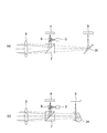
- FIGS. 1A and 1B are diagrams showing a measuring head of the present embodiment, where FIG. 1A is a diagram showing the overall configuration, and FIG. 1B is a diagram showing the configuration of an optical system.
- the measuring head 1 has a housing 2. Inside the housing 2, a light source unit 3, a first image sensor 4, a second image sensor 5, an objective optical system 6, and an optical path dividing element 7 are arranged. Further, a common optical path OPC, a first optical path OP1, and a second optical path OP2 are formed in order to arrange these elements and the like.
- the common optical path OPC is formed from the optical path dividing element 7 toward the objective optical system 6.
- the first optical path OP ⁇ b> 1 is formed from the optical path dividing element 7 toward the first imaging element 4.
- the second optical path OP2 is formed from the optical path dividing element 7 toward the second imaging element 5.
- the common optical path OPC is located on one side of the optical path splitting element 7, and the first optical path OP1 and the second optical path OP2 are located on the other side.
- an objective optical system 6 and an optical path splitting element 7 are arranged in the common optical path OPC.
- the test object 9 is arranged in the common optical path OPC.
- the objective optical system 6 is disposed closer to the test object 9 than the optical path dividing element 7, the objective optical system 6 is located closest to the test object 9. That is, there is no object other than the test object 9 in the space from the objective optical system 6 to the test object 9 side.
- the light source unit 3, the first image sensor 4, and the beam splitter 8 are arranged.
- a second image sensor 5 is disposed in the second optical path OP2. Further, the optical path splitting element 7 is arranged at a position where the first optical path OP1 and the second optical path OP2 intersect.
- the light source unit 3 is disposed in the first optical path OP1.
- the light source unit 3 is disposed at a predetermined position.
- the predetermined position is a focal position of the objective optical system 6 or a position conjugate with the focal position of the objective optical system 6. Note that the predetermined position may deviate from the focal position of the objective optical system 6 or a position conjugate with the focal position of the objective optical system 6 by several hundred microns according to the amount of aberration generated by the objective optical system 6. .
- the accuracy of these positions may vary depending on the accuracy required for the measurement head 1.
- the light source unit 3 for example, a laser, a light emitting diode, a halogen lamp, a xenon lamp, or the like is used.
- the light source unit 3 preferably has a point light source.
- a surface light source is used for the light source unit 3
- an image of the light emitting unit is formed by the optical system, and a pinhole is disposed at the image position of the light emitting unit.
- a pinhole may be disposed at the image position of the point light source.
- a light emitting diode is used as the light source unit 3.
- the wavelength of light emitted from the light emitting diode is not particularly limited. Here, red light is emitted from the light emitting diode.
- a beam splitter 8 is disposed in the first optical path OP1.
- An optical path on the light source unit 3 side and an optical path on the first imaging element 4 side are formed by the beam splitter 8.
- the light beam L1 emitted from the light source unit 3 enters the beam splitter 8.
- the beam splitter 8 is a prism having a half mirror surface. In the half mirror, incident light is divided into reflected light and transmitted light. The wavelength range of reflected light and the wavelength range of transmitted light are the same. The light intensity and transmitted light intensity of the reflected light are determined by the reflection characteristics of the half mirror.
- the beam splitter 8 may be a parallel plate having a half mirror surface.
- the light beam L 1 reflected by the beam splitter 8 enters the optical path splitting element 7.
- the optical path splitting element 7 has an optical surface that separates incident light into two. There is a half mirror as such an optical surface. Here, a prism having a half mirror surface is used for the optical path dividing element 7.
- the light beam L1 reflected by the optical path splitting element 7 enters the objective optical system 6 arranged in the common optical path OPC.
- FIG. 2 is a diagram showing a specific example of the objective optical system.
- the objective optical system 6 includes four lenses. That is, the objective optical system 6 includes a negative meniscus lens 20, a biconvex positive lens 21, a biconvex positive lens 22, and a negative meniscus lens 23.
- the negative meniscus lens 20 and the biconvex positive lens 21 are cemented.
- the biconvex positive lens 22 and the negative meniscus lens 23 are cemented.
- a light beam L2 is emitted from the objective optical system 6.
- the light source unit 3 is disposed at the focal position of the objective optical system 6. More specifically, the light emitting unit of the light source unit 3 or the image of the light emitting unit is located at the focal position of the objective optical system 6. Therefore, the light beam L2 emitted from the objective optical system 6 becomes a parallel light beam parallel to the measurement axis 10.
- the test object 9 is arranged on the common optical path OPC.
- the distance from the objective optical system 6 to the test object 9 may be adjusted by moving at least one of the test object 9 and the measurement head 1.
- the specimen 9 is irradiated with the light beam L2.
- the light beam L3 reflected by the surface of the test object 9 travels toward the objective optical system 6 through the common optical path OPC.
- the light beam L3 passes through the objective optical system 6 and enters the optical path dividing element 7. A part of the light intensity of the light beam L3 is reflected by the optical path dividing element 7. The reflected light beam L3 enters the beam splitter 8. In the beam splitter 8, a part of the light intensity of the light beam L3 is transmitted. The light beam L3 that has passed through the beam splitter 8 is incident on the first image sensor 4.
- the first image sensor 4 is, for example, a CCD or a CMOS.
- a semiconductor position detecting element may be used in place of the first imaging element 4.
- the semiconductor position detecting element has a single light receiving surface. In the semiconductor position detection element, the output current value changes according to the position of the light incident on the light receiving surface.
- the first image sensor 4 is disposed at a predetermined position.
- the predetermined position is a focal position of the objective optical system 6 or a position conjugate with the focal position of the objective optical system 6.
- the first image sensor 4 is disposed in the first optical path OP1, but when the position of the first image sensor 4 is indicated on the second optical path OP2, the first image sensor 4 is located at the position indicated by the dotted line. Is arranged. This position is coincident with the focal position of the objective optical system 6 as shown in FIG. Therefore, the light beam L3 is condensed on the first image sensor 4. That is, an image of the light source unit 3 is formed on the first image sensor 4.
- the test object 9 since the test object 9 is irradiated with the light beam L2, the test object 9 is illuminated with the light beam L2. Therefore, when attention is paid to one point on the test object 9, the light beam also travels toward the objective optical system 6 from this point.
- the light beam L ⁇ b> 4 advances from the point on the measurement axis 10 toward the objective optical system 6.
- the light beam L4 passes through the objective optical system 6 and enters the optical path dividing element 7. A part of the light beam L4 passes through the optical path dividing element 7.
- the transmitted light beam L4 enters the second image sensor 5.
- the second image sensor 5 is, for example, a CCD or a CMOS.
- the second image sensor 5 is arranged at a position different from the predetermined position.
- the predetermined position is a focal position of the objective optical system 6 or a position conjugate with the focal position of the objective optical system 6. Therefore, the test object 9 and the second image sensor 5 are optically conjugate. Since the test object 9 is irradiated with the light beam L ⁇ b> 2, an image of the test object 9 is formed on the second image sensor 5.
- an image of the light source unit 3 is formed on the first image sensor 4, and an image of the test object 9 is formed on the second image sensor 5. Using these two images, the tilt amount and the shift amount in the test object 9 can be measured.
- the test object 9 will be described using a parallel plate.
- the light beam L3 reflected by the surface of the parallel plate is the same as the light beam L2 except that the traveling direction of the light beam is opposite. That is, the light beam L3 is a parallel light beam and travels in parallel with the measurement axis 10.
- the light beam L3 is incident on a predetermined position in the first image sensor 4. As a result, an image of the light source unit 3 is formed at a predetermined position in the first image sensor 4.
- the light beam L3 is a parallel light beam, but travels with a non-zero angle with respect to the measurement axis 10. Therefore, the light beam L3 is incident on a position shifted from a predetermined position in the first image sensor 4. As a result, an image of the light source unit 3 is formed at a position shifted from a predetermined position on the first image sensor 4.
- the tilt amount of the image of the light source unit 3 can be obtained by measuring the shift amount from the predetermined position in the first image sensor 4.
- the predetermined position in the first image sensor 4 can be, for example, the center of the first image sensor 4.
- Reflected light is also generated from the back of the parallel plate. Therefore, an image of the light source unit 3 is formed by the reflected light from the back surface. However, the light intensity of this reflected light is very small. Therefore, it may be considered that the image of the light source unit 3 formed by the reflected light from the back surface cannot be detected by the first image sensor 4.
- a high contrast index at the center of the surface of the parallel plate.
- An example of such an indicator is a reticle drawn in black. In this way, the image of the reticle can be acquired with the second imaging element 5 with high contrast.
- the shape of the index is not particularly limited.
- the shift amount is zero. In this case, a reticle image is formed at a predetermined position in the second image sensor 5. On the other hand, if the amount of deviation between the center of the reticle and the measurement axis 10 is not zero, a shift has occurred. In this case, an image of the reticle is formed at a position shifted from a predetermined position in the second image sensor 5.
- the shift amount can be obtained.
- the predetermined position in the second image sensor 5 can be set at the center of the second image sensor 5, for example.
- the shift amount and the tilt amount of the test object can be measured simultaneously.
- the objective optical system is disposed closest to the object to be examined. That is, there is no object other than the test object in the space on the test object side from the objective optical system. Therefore, according to the measurement head of this embodiment, the measurement range in the measurement axis direction can be widened. As a result, the shift amount and the tilt amount of the test object can be measured simultaneously even for a test object having a long length in the measurement axis direction.
- the distance from the test object arranged in the common optical path to the objective optical system is twice the focal length of the objective optical system.
- the distance from the objective optical system 6 to the test object 9 is twice the focal length of the objective optical system 6.
- the second imaging element 5 is arranged so that the distance from the objective optical system 6 to the second imaging element 5 is about twice the focal length of the objective optical system 6.
- the distance from the objective optical system 6 to the object 9 is slightly shifted (about several hundred microns) from twice the focal length of the objective optical system 6 according to the amount of aberration generated by the objective optical system 6. May be.
- the accuracy of these positions may vary depending on the accuracy required for the measurement head 1.
- the measurement head of the present embodiment preferably has a reflecting member in the second optical path.
- the second optical path OP2 shown in FIG. 1 is a straight optical path from the optical path dividing element 7 to the second imaging element 5. Therefore, the measuring head 1 becomes large. Therefore, it is preferable to have a reflecting member in the second optical path.
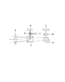
- 3A and 3B are diagrams showing an example of the arrangement of the reflecting members, where FIG. 3A is a diagram showing a first modification, and FIG. 3B is a diagram showing a second modification. The same components as those in FIG. 1A are denoted by the same reference numerals, and detailed description thereof is omitted.
- the mirror 30 is arranged in the second optical path OP2.
- the second optical path OP2 is bent once.
- the second optical path OP2 from the optical path dividing element 7 toward the second imaging element 5 is bent toward the first imaging element 4 side. Therefore, the measurement head 1 can be reduced in size in both the direction along the measurement axis 10 and the direction orthogonal to the measurement axis 10.
- the pentagonal prism 31 is arranged in the second optical path OP2.
- the optical path is bent twice by the pentagonal prism 31.
- the second optical path OP2 from the optical path dividing element 7 toward the second imaging element 5 is bent to the optical path dividing element 7 side.
- the second optical path OP2 is bent toward the first image sensor 4 by the second bending.
- the measuring head 1 can be further downsized in the direction along the measuring axis 10.
- the measurement head of this embodiment has a magnifying optical system in the second optical path.
- the image of the test object 9 is picked up by the second image pickup device 5 and the shift amount from the predetermined position in the second image pickup device 5 is measured to obtain the shift amount. Therefore, a more accurate shift amount can be obtained by measuring the position of the image of the test object 9 more accurately. Therefore, it is preferable to arrange the magnifying optical system in the second optical path.
- FIG. 4 is a diagram illustrating an arrangement example of the magnifying optical system.
- the same components as those in FIG. 3B are denoted by the same reference numerals, and detailed description thereof is omitted.
- the magnifying optical system 40 is disposed in the second optical path OP2. More specifically, the magnifying optical system 40 is disposed between the pentagonal prism 31 and the second image sensor 5. As the magnifying optical system 40, for example, a teleconverter can be used. Moreover, the magnification by the magnifying optical system 40 is, for example, 2 times.
- the image of the test object 9 formed on the second image sensor 5 is magnified by the magnification optical system 40. Thereby, the position of the image of the test object 9 can be measured more accurately.
- the magnifying optical system 40 when the magnifying optical system 40 is disposed, the pentagonal prism 31 is not necessarily disposed. That is, the magnifying optical system 40 may be disposed in the second optical path OP2 in FIG. 1 or FIG.
- the optical path dividing element is constituted by a parallel plate and has a cylindrical lens in the second optical path.
- a prism having a half mirror surface is used for the optical path dividing element 7.
- a parallel plate having a half mirror surface may be used as the optical path dividing element 7.
- the plate thickness of the parallel plate should be as thick as possible.
- the optical path splitting element 7 is disposed where the luminous flux is converged. Astigmatism occurs when a parallel plate is tilted in the convergent light beam. The amount of astigmatism generated increases as the thickness of the parallel plate increases. In this case, since the aberration of the image of the test object also increases, it is difficult to accurately measure the position of the image of the test object. Therefore, it is preferable to arrange a cylindrical lens in the second optical path.
- FIG. 5 is a diagram showing an arrangement example of cylindrical lenses.
- the same components as those in FIG. 3B are denoted by the same reference numerals, and detailed description thereof is omitted.
- a parallel plate 50 having a half mirror surface is used as the optical path splitting element 7, and a cylindrical lens 51 is disposed in the second optical path OP2. More specifically, a cylindrical lens 51 is disposed between the pentagonal prism 31 and the second image sensor 5.
- Astigmatism generated on the parallel plate 50 can be favorably corrected by the cylindrical lens 51.
- the position of the image of the test object 9 can be measured more accurately even when the parallel flat plate 50 having a large thickness is used.
- the image of the light source unit 3 formed on the first image sensor 4 can also be an image with little aberration.
- the pentagonal prism 31 is not necessarily arranged. That is, in FIG. 1 and FIG. 3A, in place of the optical path splitting element 7, the parallel plate 50 may be disposed, and the cylindrical lens 51 may be disposed in the second optical path OP2.
- the optical path dividing element has a dichroic mirror surface.
- an optical element having a half mirror surface When an optical element having a half mirror surface is used as the optical path splitting element 7, light intensity is lost on the half mirror surface. Therefore, an optical element having a dichroic mirror surface may be used as the optical path dividing element 7. Thereby, loss of light intensity can be prevented in any of the light beams L1, L2 and the light beam L3.
- incident light is divided into reflected light and transmitted light.
- the wavelength range of the reflected light and the wavelength range of the transmitted light, and the light intensity and the transmitted light intensity of the reflected light are determined by the spectral characteristics of the dichroic mirror.
- the spectral characteristics of the dichroic mirror may be such that light in a wavelength region corresponding to red is reflected and light in other wavelength regions is transmitted.
- the light beam L1 is reflected by the optical path dividing element 7 with almost no loss of light intensity.
- the test object 9 can be irradiated with the light beam L2 in a brighter state than when a half mirror is used.
- the light beam L3 reflected by the test object 9 is also reflected by the optical path dividing element 7 with almost no loss of light intensity.
- the light beam L3 can be incident on the first image sensor 4 in a brighter state than when a half mirror is used.
- a brighter image of the light source unit 3 can be obtained than when a half mirror is used.
- the measurement head of the present embodiment preferably has an illumination light source in the second optical path.
- the optical path splitting element 7 When an optical element having a dichroic mirror surface that reflects light in a wavelength region corresponding to red is used as the optical path splitting element 7 and red light is used as the light beam L4, it is reflected by the optical path splitting element 7. In this case, since the light beam L4 does not enter the second image sensor 5, the shift amount cannot be measured.
- the wavelength range of light in the light beam L4 may be different from the wavelength range in the light beam L1.
- an illumination light source for generating the light beam L4 may be prepared. Thereby, the light beam L4 is not reflected by the optical path splitting element 7.
- the illumination light source is not particularly limited as long as the wavelength region of the light beam L4 and the wavelength region of the light beam L1 are different.
- a white light source may be used as the illumination light source.
- FIG. 6A and 6B are diagrams showing an arrangement example of the light source for illumination, where FIG. 6A is a diagram showing a first arrangement example, and FIG. 6B is a diagram showing a second arrangement example.
- FIG. 6A is a diagram showing a first arrangement example
- FIG. 6B is a diagram showing a second arrangement example.
- the same components as those in FIG. 1B are denoted by the same reference numerals, and detailed description thereof is omitted.
- the illumination light source is separate from the measurement head. Specifically, as illustrated in FIG. 6A, the illumination light source 60 is disposed on the opposite side of the measurement head 1 with the test object 9 interposed therebetween.
- Illumination light is emitted from the illumination light source 60.
- the wavelength range of illumination light is different from the wavelength range of red light.
- the wavelength range of the illumination light is a wavelength range corresponding to green light.
- the light beam L4 generated from the test object 9 passes through the objective optical system 6 and enters the optical path dividing element 7.
- the light beam L4 is green light
- the optical path dividing element 7 having a dichroic mirror surface that reflects light in the wavelength region corresponding to red is used, the light beam L4 passes through the optical path dividing element 7.
- the transmitted light beam L4 enters the second image sensor 5. As a result, an image of the test object 9 is formed on the second image sensor 5.
- the light beam L4 is light that has passed through the test object 9 and the optical path dividing element 7, so that there is little loss of light intensity. Therefore, when a reticle is formed on the test object 9, an image of the reticle can be acquired with a high contrast by the second image sensor 5. However, since the illumination light source 60 is separate from the measuring head 1, it takes time to adjust the position.
- the illumination light source is arranged in the measurement head 1. Specifically, as shown in FIG. 6B, the illumination light source 61 is disposed in the second optical path OP2.
- Illumination light is emitted from the illumination light source 61.
- the wavelength range of illumination light is different from the wavelength range of red light.
- the wavelength range of the illumination light is a wavelength range corresponding to blue light.
- the illumination light is reflected by the beam splitter 62 and enters the optical path dividing element 7.
- the illumination light passes through the optical path dividing element 7.
- the illumination light passes through the objective optical system 6 and is irradiated onto the test object 9. Since the illumination is performed from the same side as the objective optical system 6, the test object 9 is incidentally illuminated.
- the light beam L4 generated from the test object 9 passes through the objective optical system 6 and enters the optical path dividing element 7.
- the light beam L4 is blue light
- the light beam L4 passes through the optical path dividing element 7.
- the transmitted light beam L4 enters the second image sensor 5.
- an image of the test object 9 is formed on the second image sensor 5.
- the loss of light intensity is larger than that in the first arrangement example.
- the illumination light source 61 is integrated with the measurement head 1, it does not require time for position adjustment.
- the eccentricity measuring apparatus of the present embodiment includes a main body, a moving mechanism, a measuring head, a holding member, and a processing device, and the measuring head, the holding member, and the moving mechanism are provided in the main body, The measurement head and the holding member are positioned so that the measurement head and the object held by the holding member are positioned on the measurement axis, and the moving mechanism measures at least one of the measurement head and the holding member.
- the processing apparatus is connected to a moving mechanism and a measurement head, and the measurement head is the measurement head described above.
- FIG. 7 is a diagram showing the eccentricity measuring apparatus of the present embodiment.
- the eccentricity measuring device 70 includes a main body 71, a moving mechanism 72, a measuring head 73, a holding member 74, and a processing device 75.
- the moving mechanism 72, the measuring head 73, and the holding member 74 are provided on the main body 71.
- the moving mechanism 72 is fixed to the main body 71.
- the moving mechanism 72 is, for example, a linear stage.
- a measuring head 73 is placed on the moving mechanism 72 via an adjusting mechanism 76.
- the holding member 74 is fixed to the main body 71 via an adjustment mechanism 77.
- the holding member 74 holds a test object (not shown).
- the measurement head 73 and the test object are located on the measurement axis 79.
- the measurement head 73 and the holding member 74 are positioned so as to be like this.
- An adjustment mechanism 76 and an adjustment mechanism 77 are used for this positioning.
- the measuring head 73 may be directly attached to the moving mechanism 72, and the holding member 74 may be replaced for each test object. By doing so, the measurement head 73 and the test object held by the holding member 74 can be positioned on the measurement shaft 79. In this case, the adjustment mechanism 76 and the adjustment mechanism 77 are unnecessary.
- the moving mechanism 72 moves the measurement head 73 in a direction along the measurement axis. Thereby, the space
- the moving mechanism 72 may be disposed toward the holding member 74. Furthermore, a movement mechanism may be provided on both the measurement head 73 and the holding member 74.
- the processing device 75 is connected to the moving mechanism 72 and the measuring head 73. In accordance with an instruction from the processing device 75, the moving mechanism 72 is driven, and thereby the position of the measuring head 73 is adjusted. Further, information obtained by the measurement head 73 is sent to the processing device 75, and various processing is performed by the processing device 75.
- an illumination light source 78 may be provided on the main body 71.
- the illumination light source 78 is disposed at a position facing the measurement head 73 with the holding member 74 interposed therebetween.
- the illumination light source 78 and the processing device 75 are connected. Thereby, the illumination light source 78 can be controlled.
- the test object is a lens barrel of a single focus optical system.
- the single focus optical system is assumed to be composed of five single lenses.
- “linear stage 72” is used instead of “moving mechanism 72”.
- FIG. 8 is a diagram showing an example of a lens barrel. Since the single focus optical system is composed of five single lenses, the number of lens frames holding the lenses is five. As shown in FIG. 8, a lens frame 81, a lens frame 82, a lens frame 83, a lens frame 84, and a lens frame 85 are inserted inside the lens barrel 80.
- the lens frame 81 has an opening for holding the lens.
- a surface for receiving the lens (hereinafter referred to as “receiving surface”) is formed in the opening.
- the angle between the normal of the receiving surface and the central axis of the lens frame 81 is preferably zero. However, if there is a processing error, the angle between the normal of the receiving surface and the central axis of the lens frame 81 does not become zero. In this case, the opening is tilted.
- the opening is formed at the center of the lens frame 81. However, if there is a processing error, an opening is formed at a position shifted from the center of the lens frame 81. In this case, a shift occurs in the opening.
- the lens frame 82, the lens frame 83, the lens frame 84, and the lens frame 85 are the same as the lens frame 81.
- each lens frame is inserted into the lens barrel 80 while the lens is held by each of the lens frames 81 to 85, the imaging performance of the single focus optical system is degraded. Therefore, it is important to be able to measure the tilt amount and the shift amount in each lens frame.
- the lens frame can be reprocessed based on the measurement result. Thereby, the tilt amount and the shift amount in the lens frame can be reduced.
- the measurement result is fed back to the first processing step. By doing so, the tilt amount and the shift amount can be reduced in the lens frame manufactured in the first processing step.
- FIG. 9 is a diagram showing a measurement flat plate.
- the measurement flat plate 100 is a transparent parallel plate 101.
- a reticle 102 is formed on one surface of the parallel plate 101.
- the reticle 102 is accurately formed at the center of the parallel plate 101.
- Such a measurement flat plate 100 is held by lens frames 81 to 85.
- the measurement flat plate 86 is held by the lens frame 81
- the measurement flat plate 87 is held by the lens frame 82
- the measurement flat plate 88 is held by the lens frame 83
- the measurement flat plate 89 is held by the lens frame 84.
- the measurement flat plate 90 is held by the lens frame 85.
- the opening is shifted to the right, and the normal of the receiving surface is directed to the upper left diagonally upward direction.
- the opening is not shifted, and the normal line of the receiving surface faces obliquely upward to the left.
- the opening is shifted to the right, and the normal of the receiving surface is directed obliquely upward to the left.
- the opening is shifted leftward, and the normal line of the receiving surface is directed obliquely upward to the right.
- the opening is not shifted, and the normal line of the receiving surface is directed obliquely upward to the right.
- left and right and up and down means up and down in the drawing.
- a jig 91 is disposed on one side of the lens barrel 80.
- the jig 91 includes a lens frame 92 and a measurement flat plate 93.
- the opening of the lens frame 92 is formed with high accuracy. Therefore, both the tilt amount and the shift amount in the lens frame 92 are almost zero.
- the lens barrel 80 and the jig 91 Prior to measurement, the lens barrel 80 and the jig 91 are held by the holding member 74. At this time, the lens barrel 80 and the jig 91 are held so that the lens barrel 80 is positioned closer to the measuring head 73 than the jig 91.
- the measuring head 73 is disposed at a position facing the lens barrel 80.
- the measurement head 73 moves along the measurement axis 79 by the linear stage 72 during measurement.
- the linear stage 72 and the measuring head 73 are attached to the main body 71 such that the measuring shaft 79 is perpendicular to the surface of the measuring flat plate 93 on the jig 91.
- each of the jig 91, the linear stage 72, and the measuring head 73 may be provided with a machine for adjusting the inclination. This adjustment may be performed as necessary. By doing so, it is possible to perform a measurement in which the perpendicularity of the measuring flat plate 93 and the measuring head 73 is guaranteed.
- the linear stage 72 is also provided with an adjustment mechanism.
- the measurement head 73 is moved to the reference position on the linear stage 72.
- This reference position is a position representing a mechanical origin. Thereby, the measurement head 73 can be returned to the mechanical origin.
- the light beam L1 is emitted from the light source unit 3 of the measuring head 73, and the light beam L2 is applied to the lens barrel 80 and the jig 91.
- illumination light is applied to the lens barrel 80 and the jig 91 from the illumination light source.
- illumination light is emitted from the illumination light source 78 to the lens barrel 80 and the jig 91.
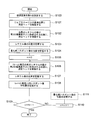
- FIG. 10 is a flowchart of the measurement method.
- step S100 the number of measured surfaces is set.
- step S101 the measuring head 73 is moved to the reference position on the linear stage 72. This prepares for measurement.
- the jig 91 is measured.
- an image Io of the reticle 102 of the measurement flat plate 93 (hereinafter referred to as “reticle image Io”) can be formed. Therefore, in step S102, the measurement head 73 is moved to form a reticle image Io on the second image sensor 5.
- the contrast of the reticle image Io may be obtained while moving the measurement head 73, and the movement of the measurement head 73 may be stopped when the contrast of the reticle image Io reaches the maximum. In this way, the reticle 102 can be automatically focused.
- a clear reticle image Io is formed on the second image sensor 5. Therefore, the reticle image Io is imaged to obtain the coordinates So ( ⁇ xo, ⁇ yo) of the reticle image Io. In step S103, the calculated So ( ⁇ xo, ⁇ yo) is stored.
- spot image an image of the light source unit 3 (hereinafter referred to as “spot image”) is formed on the first image sensor 4. Since the number of measurement flat plates is 6, the number of spot images is 6. Six spot images are generated by reflection on the surfaces of the measurement flat plates 86 to 90 and 93. The light intensity of the light beam L2 decreases as it passes through the measurement flat plate. Therefore, the brightness of the six spot images is different.
- the brightest spot image is an image resulting from reflection from a measurement flat plate located closest to the measurement head 73.
- the darkest spot image is an image resulting from reflection from a measurement flat plate located farthest from the measurement head 73.
- the measurement flat plate 93 is located farthest from the measurement head 73. Therefore, the darkest spot image is identified from the six spot images, and the coordinates To ( ⁇ xo, ⁇ yo) of the darkest spot image are obtained. In step S104, the obtained To ( ⁇ xo, ⁇ yo) is stored.
- the position Zo (zo) of the measurement head 73 on the measurement axis 79 is stored. Thereby, the measurement of the position of the reticle image and the measurement of the position of the spot image on the jig 91 are completed.
- step S105 the value of n is initialized.
- the reticle 102 of the measurement flat plate 93 is in focus. Therefore, efficient measurement can be performed by measuring the position of the reticle image and the position of the spot image from the measurement flat plate positioned closest to the measurement flat plate 93.
- the order of measuring the measurement flat plate may be from the measurement flat plate positioned farthest from the measurement flat plate 93 or may be random.
- the measurement flat plate located closest to the measurement flat plate 93 is the measurement flat plate 90.
- the measurement flat plate 90 is located closer to the measurement head 73 than the measurement flat plate 93. Therefore, in step S106, the measurement head 73 is moved away from the lens barrel 80 to form the reticle image I 1 on the second image sensor 5.
- the reticle image I 1 is an image of a reticle formed on the measurement flat plate 90. In this case also, it obtains the contrast of the reticle image I 1, when the contrast of the reticle image I 1 is maximized, the movement of the measuring head 73 may be stopped.
- a clear reticle image I 1 is formed on the second image sensor 5. Therefore, the reticle image I 1 is imaged to obtain the coordinates S 1 ( ⁇ x1, ⁇ y1) of the reticle image I 1 of the measurement flat plate 90. In step S107, the obtained S 1 ( ⁇ x1, ⁇ y1) is stored.
- the position of the measurement flat plate 90 is a position farthest from the measurement head 73. Therefore, the second dark spot image is identified from the six spot images, and the coordinate T 1 ( ⁇ x1, ⁇ y1) of the second darkest spot image is obtained. In step S108, the calculated T 1 ( ⁇ x1, ⁇ y1) is stored.
- step S109 the number of measurements is confirmed. When n and N-1 do not match, measurement on all the measurement flat plates is not completed. In this case, step S110 is executed. In step S110, the value of variable n is incremented.
- step S111 is executed. Step S111 may be executed as necessary.
- the coordinates of the darkest spot image have already been obtained by measurement on the measurement flat plate 93 (step S104).
- the position of the measurement head 73 differs between the measurement on the measurement flat plate 90 and the measurement on the measurement flat plate 93. Therefore, the coordinates measured on the measurement flat plate 90 and the coordinates measured on the measurement flat plate 93 may not always match. This point will be described later.
- the processing performed on the measurement flat plate 90 is repeated in the order of the measurement flat plate 89, the measurement flat plate 88, the measurement flat plate 87, and the measurement flat plate 86.
- the measurement data of the position of the reticle image and the measurement data of the position of the spot image are stored in the processing device 75 together with the position data of the measurement head 73.
- the tilt amount and the shift amount in each lens frame can be obtained.
- the normal of the surface of the measurement flat plate 93 and the measurement axis 79 are parallel. However, it is very difficult to make them completely parallel. In a state where the normal of the surface of the measurement flat plate 93 and the measurement axis 79 intersect, when the measurement head 73 moves along the measurement axis 79, the measurement is also performed in a direction orthogonal to the normal of the surface of the measurement flat plate 93. The head 73 moves. Such movement causes an error in the measurement of the position of the reticle image and the measurement of the position of the spot image. As a cause of an error caused by the movement of the measuring head 73, there are pitching and yawing in the measuring head 73.
- the measurement head 73 uses the measurement data of the coordinates of the darkest spot image to shift due to pitching in the measurement head 73.
- the amount of deviation due to the amount or yawing can be detected.
- the eccentricity measurement can be performed with high accuracy.
- the parallelism and coaxiality of the in-cylinder structure can be easily measured without contact.
- the measurement head 73 can be used as an autocollimator. That is, the eccentricity measuring device 70 may be a device that measures the tilt amount in the lens frame without obtaining the shift amount in the lens frame. In this case, the tilt amount can be simultaneously measured for a plurality of measurement flat plates.
- the present invention is suitable for a measuring head having a wide measuring range in the measuring axis direction and an eccentricity measuring apparatus including the measuring head.
Landscapes
- Physics & Mathematics (AREA)
- General Physics & Mathematics (AREA)
- Optics & Photonics (AREA)
- Chemical & Material Sciences (AREA)
- Analytical Chemistry (AREA)
- Engineering & Computer Science (AREA)
- Multimedia (AREA)
- Human Computer Interaction (AREA)
- Signal Processing (AREA)
- Length Measuring Devices By Optical Means (AREA)
Abstract
測定ヘッド1は、光源部3と、第1の撮像素子4と、第2の撮像素子5と、対物光学系6と、光路分割素子7と、共通光路OPCと、第1の光路OP1と、第2の光路OP2と、を備え、共通光路OPCは、光路分割素子7から対物光学系6に向かって形成され、第1の光路OP1は、光路分割素子7から第1の撮像素子4に向かって形成され、第2の光路OP2は、光路分割素子7から第2の撮像素子5に向かって形成され、光路分割素子7を挟んで一方の側に共通光路OPCが位置し、他方の側に第1の光路OP1と第2の光路OP2とが位置し、光路分割素子7は、第1の光路OP1と第2の光路OP2とが交差する位置に配置され、光源部3と第1の撮像素子4は、共に所定の位置に配置され、第2の撮像素子5は、所定の位置と異なる位置に配置され、所定の位置は、対物光学系6の焦点位置、又は対物光学系6の焦点位置と共役な位置である。
Description
本発明は、測定軸方向における測定範囲が広い測定ヘッド及びそれを備えた偏心測定装置に関する。
被検物における偏心量を測定する装置として、偏心測定装置がある。偏心は、チルトとシフトで表すことができる。例えば、被検物が平行平板の場合、チルト量は、平行平板の面の法線と基準軸とのなす角で表すことができる。また、シフト量は、平行平板の中心と基準軸とのずれ量で表すことができる。
チルト量を測定する装置は、オートコリメータと呼ばれる。オートコリメータを備えた角度測定装置として、特許文献1に記載された装置がある。
特許文献1に記載された装置は、2つのCCDカメラを有する。一方のCCDカメラは、凸レンズの焦点位置に配置されている。他方のCCDカメラは、凸レンズの焦点位置とは異なる位置に配置されている。また、被測定物体と凸レンズとの間に、ビームスプリッタが配置されている。特許文献1に記載された装置では、チルト量とシフト量が得られる。
特許文献1に記載された装置では、被検物と凸レンズとの間にビームスプリッタが配置されている。そのため、例えば、円筒状のガラスブロックの両面を測定する場合、両面の間隔が広すぎると、凸レンズから遠い方の面におけるシフト量の測定ができなくなる恐れがある。
すなわち、凸レンズから遠い方の面におけるシフト量を測定するためには、この面にピントを合わせる必要がある。そのためには、角度測定器と被検物の間隔を、狭くしなくてはならない。しかしながら、両面の間隔が広すぎると、この面にピントがあう前に、凸レンズに近い方の面がビームスプリッタに接触してしまう。
本発明は、上記に鑑みてなされたものであって、測定軸方向における測定範囲が広い測定ヘッド及びそれを備えた偏心測定装置を提供することを目的としている。
上述した課題を解決し、目的を達成するために、本発明の測定ヘッドは、
光源部と、第1の撮像素子と、第2の撮像素子と、対物光学系と、光路分割素子と、共通光路と、第1の光路と、第2の光路と、を備え、
共通光路は、光路分割素子から対物光学系に向かって形成され、
第1の光路は、光路分割素子から第1の撮像素子に向かって形成され、
第2の光路は、光路分割素子から第2の撮像素子に向かって形成され、
光路分割素子を挟んで一方の側に共通光路が位置し、他方の側に第1の光路と第2の光路とが位置し、
光路分割素子は、第1の光路と第2の光路とが交差する位置に配置され、
光源部は、第1の光路に配置され、
光源部と第1の撮像素子は、共に所定の位置に配置され、
第2の撮像素子は、所定の位置と異なる位置に配置され、
所定の位置は、対物光学系の焦点位置、又は対物光学系の焦点位置と共役な位置であることを特徴とする。
光源部と、第1の撮像素子と、第2の撮像素子と、対物光学系と、光路分割素子と、共通光路と、第1の光路と、第2の光路と、を備え、
共通光路は、光路分割素子から対物光学系に向かって形成され、
第1の光路は、光路分割素子から第1の撮像素子に向かって形成され、
第2の光路は、光路分割素子から第2の撮像素子に向かって形成され、
光路分割素子を挟んで一方の側に共通光路が位置し、他方の側に第1の光路と第2の光路とが位置し、
光路分割素子は、第1の光路と第2の光路とが交差する位置に配置され、
光源部は、第1の光路に配置され、
光源部と第1の撮像素子は、共に所定の位置に配置され、
第2の撮像素子は、所定の位置と異なる位置に配置され、
所定の位置は、対物光学系の焦点位置、又は対物光学系の焦点位置と共役な位置であることを特徴とする。
また、本発明の偏心測定装置は、
本体部と、移動機構と、測定ヘッドと、保持部材と、処理装置と、を備え、
測定ヘッド、保持部材及び移動機構は、本体部に設けられ、
測定ヘッドと保持部材で保持された被検物とが、測定軸上に位置するように、測定ヘッドと保持部材が位置決めされており、
移動機構は、測定ヘッドと保持部材の少なくとも一方を、測定軸に沿う方向に移動させ、
処理装置は、移動機構と測定ヘッドとに接続され、
測定ヘッドが、上述の測定ヘッドであることを特徴とする。
本体部と、移動機構と、測定ヘッドと、保持部材と、処理装置と、を備え、
測定ヘッド、保持部材及び移動機構は、本体部に設けられ、
測定ヘッドと保持部材で保持された被検物とが、測定軸上に位置するように、測定ヘッドと保持部材が位置決めされており、
移動機構は、測定ヘッドと保持部材の少なくとも一方を、測定軸に沿う方向に移動させ、
処理装置は、移動機構と測定ヘッドとに接続され、
測定ヘッドが、上述の測定ヘッドであることを特徴とする。
本発明によれば、測定軸方向における測定範囲が広い測定ヘッド及びそれを備えた偏心測定装置を提供できる。
本発明のある態様にかかる実施形態の作用効果を説明する。なお、本実施形態の作用効果を具体的に説明するに際しては、具体的な例を示して説明することになる。しかし、それらの例示される態様はあくまでも本発明に含まれる態様のうちの一部に過ぎず、その態様には数多くのバリエーションが存在する。したがって、本発明は例示される態様に限定されるものではない。
本実施形態の測定ヘッドは、光源部と、第1の撮像素子と、第2の撮像素子と、対物光学系と、光路分割素子と、共通光路と、第1の光路と、第2の光路と、を備え、共通光路は、光路分割素子から対物光学系に向かって形成され、第1の光路は、光路分割素子から第1の撮像素子に向かって形成され、第2の光路は、光路分割素子から第2の撮像素子に向かって形成され、光路分割素子を挟んで一方の側に共通光路が位置し、他方の側に第1の光路と第2の光路とが位置し、光路分割素子は、第1の光路と第2の光路とが交差する位置に配置され、光源部は、第1の光路に配置され、光源部と第1の撮像素子は、共に所定の位置に配置され、第2の撮像素子は、所定の位置と異なる位置に配置され、所定の位置は、対物光学系の焦点位置、又は対物光学系の焦点位置と共役な位置であることを特徴とする。
図1は本実施形態の測定ヘッドを示す図であって、(a)は全体構成を示す図、(b)は光学系の構成を示す図である。
測定ヘッド1は筐体2を有する。筐体2の内部には、光源部3と、第1の撮像素子4と、第2の撮像素子5と、対物光学系6と、光路分割素子7と、が配置されている。また、これらの素子等を配置するめに、共通光路OPC、第1の光路OP1及び第2の光路OP2が形成されている。
共通光路OPCは、光路分割素子7から対物光学系6に向かって形成されている。第1の光路OP1は、光路分割素子7から第1の撮像素子4に向かって形成されている。第2の光路OP2は、光路分割素子7から第2の撮像素子5に向かって形成されている。
光路分割素子7を挟んで一方の側に共通光路OPCが位置し、他方の側に第1の光路OP1と第2の光路OP2とが位置している。
共通光路OPCには、対物光学系6と光路分割素子7とが配置されている。また、共通光路OPCには被検物9が配置される。ここで、対物光学系6は光路分割素子7よりも被検物9側に配置されているので、対物光学系6が被検物9に対して最も近くに位置する。すなわち、対物光学系6から被検物9側の空間には、被検物9以外の物は何も存在しない。
第1の光路OP1には、光源部3と、第1の撮像素子4と、ビームスプリッタ8と、が配置されている。第2の光路OP2には、第2の撮像素子5が配置されている。また、第1の光路OP1と第2の光路OP2とが交差する位置に、光路分割素子7が配置されている。
光源部3は、第1の光路OP1に配置されている。光源部3は、所定の位置に配置されている。所定の位置は、対物光学系6の焦点位置、又は対物光学系6の焦点位置と共役な位置である。なお、対物光学系6によって生じる収差量等に応じて、所定の位置は、対物光学系6の焦点位置、又は対物光学系6の焦点位置と共役な位置から数百ミクロン程度ずれていても良い。これらの位置の精度は、測定ヘッド1に求められる精度によって、異なる場合がある。
光源部3には、例えば、レーザ、発光ダイオード、ハロゲンランプ、キセノンランプ等が用いられる。光源部3は点光源を有することが好ましい。光源部3に面光源を用いる場合、光学系によって発光部の像を形成し、発光部の像位置にピンホールを配置する。光源部3に点光源を用いる場合も、点光源の像を形成し、点光源の像位置にピンホールを配置して良い。
図1(b)では、光源部3として発光ダイオードが用いられている。発光ダイオードから射出される光の波長は特に限定されない。ここでは、赤色光が発光ダイオードから射出される。
第1の光路OP1には、ビームスプリッタ8が配置されている。ビームスプリッタ8によって、光源部3側の光路と第1の撮像素子4側の光路が形成されている。光源部3から射出した光束L1は、ビームスプリッタ8に入射する。
ビームスプリッタ8は、ハーフミラー面を有するプリズムである。ハーフミラーでは、入射光が反射光と透過光に分割される。反射光の波長域と透過光の波長域は同じである。また、反射光の光強度と透過光強度は、ハーフミラーの反射特性で決まる。ビームスプリッタ8は、ハーフミラー面を有する平行平板でも良い。
ビームスプリッタ8で反射された光束L1は、光路分割素子7に入射する。光路分割素子7は、入射した光を2つに分離する光学面を有する。このような光学面としてハーフミラーがある。ここでは、光路分割素子7に、ハーフミラー面を有するプリズムが用いられている。光路分割素子7で反射された光束L1は、共通光路OPCに配置された対物光学系6に入射する。
図2は、対物光学系の具体例を示す図である。図2に示すように、対物光学系6は4枚のレンズで構成されている。すなわち、対物光学系6は、負メニスカスレンズ20と、両凸正レンズ21と、両凸正レンズ22と、負メニスカスレンズ23と、で構成されている。ここで、負メニスカスレンズ20と両凸正レンズ21とが接合されている。また、両凸正レンズ22と負メニスカスレンズ23とが接合されている。
図1に戻って説明を続ける。対物光学系6から光束L2が射出する。ここで、光源部3は、対物光学系6の焦点位置に配置されている。より詳しくは、光源部3の発光部、又は、発光部の像が対物光学系6の焦点位置に位置している。そのため、対物光学系6から射出した光束L2は、測定軸10と平行な平行光束になる。
共通光路OPC上には、被検物9が配置されている。対物光学系6から被検物9までの距離の調整は、被検物9と測定ヘッド1の少なくとも一方を移動させれば良い。
被検物9には光束L2が照射される。被検物9では、照射された光束L2の光強度の少なくとも一部が被検物9の表面で反射される。被検物9の表面で反射された光束L3は、共通光路OPCを対物光学系6に向かって進む。
光束L3は対物光学系6を通過して、光路分割素子7に入射する。光束L3の光強度の一部は光路分割素子7で反射される。反射された光束L3は、ビームスプリッタ8に入射する。ビームスプリッタ8では、光束L3の光強度の一部が透過される。ビームスプリッタ8を透過した光束L3は、第1の撮像素子4に入射する。第1の撮像素子4は、例えば、CCDやCMOSである。
第1の撮像素子4に代えて、半導体位置検出素子を用いても良い。半導体位置検出素子は、単一の受光面を有する。半導体位置検出素子では、受光面に入射した光の位置に応じて、出力される電流値が変化する。
第1の撮像素子4は、所定の位置に配置されている。上述のように、所定の位置は、対物光学系6の焦点位置、又は対物光学系6の焦点位置と共役な位置である。
第1の撮像素子4は第1の光路OP1に配置されているが、第1の撮像素子4の位置を第2の光路OP2上に示すと、第1の撮像素子4は点線で示す位置に配置されている。この位置は、図1(a)に示すように、対物光学系6の焦点位置と一致している。よって、光束L3は、第1の撮像素子4上に集光する。すなわち、光源部3の像が、第1の撮像素子4上に形成される。
また、被検物9には光束L2が照射されているので、被検物9は光束L2で照明されていることになる。そこで、被検物9上の一点に着目すると、この点からも光束が対物光学系6に向かって進む。図1では、測定軸10上の点から、光束L4が対物光学系6に向かって進んでいる。
光束L4は対物光学系6を通過して、光路分割素子7に入射する。光束L4の一部は光路分割素子7を透過する。透過した光束L4は、第2の撮像素子5に入射する。第2の撮像素子5は、例えば、CCDやCMOSである。
第2の撮像素子5は、所定の位置とは異なる位置に配置されている。上述のように、所定の位置は、対物光学系6の焦点位置、又は対物光学系6の焦点位置と共役な位置である。よって、被検物9と第2の撮像素子5とは、光学的に共役になる。被検物9には光束L2が照射されているので、第2の撮像素子5上に被検物9の像が形成される。
このように、測定ヘッド1では、第1の撮像素子4には光源部3の像が形成され、第2の撮像素子5上に被検物9の像が形成される。この2つの像を使って、被検物9におけるチルト量とシフト量を測定することができる。以下、被検物9として平行平板を用いて説明する。
平行平板の表面の法線(以下、「面の法線」という)と測定軸10とのなす角がゼロの場合、チルトは発生していない。この場合、平行平板の表面で反射された光束L3は、光束の進行方向が反対であることを除いて、光束L2と同一になる。すなわち、光束L3は平行光束で、且つ、測定軸10と平行に進む光束になる。光束L3は、第1の撮像素子4における所定の位置に入射する。その結果、第1の撮像素子4における所定の位置に、光源部3の像が形成される。
一方、面の法線と測定軸10とのなす角がゼロでない場合、チルトが発生している。この場合、光束L3は平行光束ではあるが、測定軸10とゼロでない角度を有して進行する。そのため、光束L3は、第1の撮像素子4における所定の位置からずれた位置に入射する。その結果、第1の撮像素子4における所定の位置からずれた位置に、光源部3の像が形成される。
このように、光源部3の像について、第1の撮像素子4における所定の位置からのずれ量を測定することで、チルト量を求めることができる。第1の撮像素子4における所定の位置は、例えば、第1の撮像素子4の中心にすることができる。
平行平板の裏面からも反射光が生じる。よって、裏面からの反射光によって、光源部3の像が形成される。しかしながら、この反射光の光強度は非常に小さい。よって、裏面からの反射光によって形成された光源部3の像は、第1の撮像素子4では検出できないと考えて良い。
平行平板の中心と測定軸10とのずれ量がゼロの場合、シフトは発生していない。一方、平行平板の中心と測定軸10とのずれ量がゼロでない場合、シフトが発生している。第1の撮像素子4上に形成される光源部3の像の位置は、ずれ量がゼロの場合であっても、ずれ量がゼロでない場合であっても変化しない。よって、第1の撮像素子4ではシフトを検出できない。
これに対して、第2の撮像素子5には、被検物9である平行平板の表面の像が形成される。よって、平行平板の中心と測定軸10とのずれは、第2の撮像素子5で検出することができる。ただし、平行平板の表面の像はコントラストが低いので、ずれ量を正確に測定することは難しい。
このようなことから、平行平板の表面の中心に、コントラストの高い指標を形成しておくことが好ましい。このような指標としては、例えば、黒色で描かれたレチクルがある。このようにしておくと、高いコントラストでレチクルの像を第2の撮像素子5で取得することができる。なお、指標の形状は、特に限定されない。
レチクルの中心と測定軸10とのずれ量がゼロの場合、シフトは発生していないのでシフト量はゼロである。この場合、第2の撮像素子5における所定の位置に、レチクルの像が形成される。一方、レチクルの中心と測定軸10とのずれ量がゼロでない場合、シフトが発生している。この場合、第2の撮像素子5における所定の位置からずれた位置に、レチクルの像が形成される。
このようにレチクルの像について、第2の撮像素子5における所定の位置からのずれ量を測定することで、シフト量を求めることができる。第2の撮像素子5における所定の位置は、例えば、第2の撮像素子5の中心にすることができる。
このように、本実施形態の測定ヘッドによれば、被検物のシフト量とチルト量を同時に測定することができる。
更に、本実施形態の測定ヘッドでは、対物光学系が、被検物に対して最も近くに配置されている。すなわち、対物光学系から被検物側の空間には、被検物以外の物は何も存在しない。よって、本実施形態の測定ヘッドによれば、測定軸方向の測定範囲を広くすることができる。その結果、測定軸方向の長さが長い被検物であっても、被検物のシフト量とチルト量を同時に測定することができる。
また、本実施形態の測定ヘッドでは、共通光路に配置された被検物から対物光学系までの距離が、対物光学系の焦点距離の2倍であることが好ましい。
図1(a)に示すように、本実施形態の測定ヘッドでは、対物光学系6から被検物9までの距離は、対物光学系6の焦点距離の2倍になっている。これに伴い、対物光学系6から第2の撮像素子5までの距離が対物光学系6の焦点距離の約2倍となるように、第2の撮像素子5は配置されている。このようにすることで、有限距離に位置するレチクル像を精度よく検出できる。
なお、対物光学系6によって生じる収差量等に応じて、対物光学系6から被検物9までの距離は、対物光学系6の焦点距離の2倍から微小に(数百ミクロン程度)ずれていてもよい。これらの位置の精度は、測定ヘッド1に求められる精度によって、異なる場合がある。
また、本実施形態の測定ヘッドは、第2の光路中に反射部材を有することが好ましい。
図1に示す第2の光路OP2は、光路分割素子7から第2の撮像素子5までが一直線の光路になっている。そのため、測定ヘッド1が大型になる。そこで、第2の光路中に反射部材を有することが好ましい。
図3は反射部材の配置例を示す図であって、(a)は第1の変形例を示す図、(b)は第2の変形例を示す図である。図1(a)と同じ構成については同じ番号を付し、詳細な説明は省略する。
図3は反射部材の配置例を示す図であって、(a)は第1の変形例を示す図、(b)は第2の変形例を示す図である。図1(a)と同じ構成については同じ番号を付し、詳細な説明は省略する。
第1の変形例では、第2の光路OP2中にミラー30が配置されている。ミラー30を配置することで、第2の光路OP2が1回折り曲げられる。この折り曲げによって、光路分割素子7から第2の撮像素子5に向かう第2の光路OP2は第1の撮像素子4側に折り曲げられる。よって、測定軸10に沿う方向と、測定軸10と直交する方向の両方向で、測定ヘッド1を小型化することができる。
第2の変形例では、第2の光路OP2中にペンタゴナルプリズム31が配置されている。ペンタゴナルプリズム31により、2回光路が折り曲げられる。1回目の折り曲げによって、光路分割素子7から第2の撮像素子5に向かう第2の光路OP2は光路分割素子7側に折り曲げられる。そして、2回目の折り曲げによって、第2の光路OP2は第1の撮像素子4側に折り曲げられる。
第2の変形例では、光路分割素子7側への折り曲げが行われている。そのため、第2の変形例では、測定軸10に沿う方向において、測定ヘッド1を更に小型化することができる。
また、本実施形態の測定ヘッドは、第2の光路中に拡大光学系を有することが好ましい。
上述のように、第2の撮像素子5で被検物9の像を撮像し、第2の撮像素子5における所定の位置からのずれ量を測定することでシフト量を求めている。よって、被検物9の像の位置をより正確に測定することで、より正確なシフト量を求めることができる。そこで、第2の光路中に拡大光学系を配置することが好ましい。
図4は、拡大光学系の配置例を示す図である。図3(b)と同じ構成については同じ番号を付し、詳細な説明は省略する。
図4に示すように、第2の光路OP2中に拡大光学系40が配置されている。より詳細には、ペンタゴナルプリズム31と第2の撮像素子5との間に、拡大光学系40が配置されている。拡大光学系40として、例えば、テレコンバータを用いることができる。また、拡大光学系40による拡大倍率は、例えば2倍である。
拡大光学系40によって、第2の撮像素子5上に形成される被検物9の像が拡大される。これにより、被検物9の像の位置をより正確に測定することができる。なお、拡大光学系40を配置する場合、必ずしもペンタゴナルプリズム31を配置しなくてもよい。すなわち、図1や図3(a)の第2の光路OP2中に拡大光学系40を配置してもよい。
また、本実施形態の測定ヘッドでは、光路分割素子は平行平板で構成され、第2の光路中にシリンドリカルレンズを有することが好ましい。
図1(a)では、光路分割素子7に、ハーフミラー面を有するプリズムが用いられている。しかしながら、光路分割素子7として、ハーフミラー面を有する平行平板を用いても良い。ここで、ハーフミラー面の平面度が低いと、対物光学系6から射出する光束を平行にすることが困難になる他、第1の撮像素子4上に形成される光源部3の像にも収差が生じる。よって、ハーフミラー面の平面度を高く保つためには、平行平板の板厚はできるだけ厚い方が良い。
しかしながら、光路分割素子7は光束が収斂している所に配置されている。収斂光束中に平行平板を傾けて配置すると、非点収差が発生する。非点収差の発生量は、平行平板の厚みが増すほど多くなる。この場合、被検物の像の収差も増すので、被検物の像の位置を正確に計測することが困難になる。そこで、第2の光路中にシリンドリカルレンズを配置することが好ましい。
図5は、シリンドリカルレンズの配置例を示す図である。図3(b)と同じ構成については同じ番号を付し、詳細な説明は省略する。
図5では、光路分割素子7として、ハーフミラー面を有する平行平板50が用いられ、第2の光路OP2中にシリンドリカルレンズ51が配置されている。より詳細には、ペンタゴナルプリズム31と第2の撮像素子5との間に、シリンドリカルレンズ51が配置されている。
シリンドリカルレンズ51によって、平行平板50で発生する非点収差を良好に補正することができる。その結果、厚みの大きい平行平板50を用いても、被検物9の像の位置をより正確に測定することができる。また、第1の撮像素子4上に形成される光源部3の像も、収差の少ない像にすることができる。
なお、平行平板50と、シリンドリカルレンズ51と、を配置する場合、必ずしもペンタゴナルプリズム31を配置しなくてもよい。すなわち、図1や図3(a)において、光路分割素子7に代えて、平行平板50を配置するとともに、第2の光路OP2中にシリンドリカルレンズ51を配置してもよい。
また、本実施形態の測定ヘッドは、光路分割素子はダイクロイックミラー面を有することが好ましい。
光路分割素子7に、ハーフミラー面を有する光学素子を用いた場合、ハーフミラー面で光強度の損失が生じる。そこで、光路分割素子7に、ダイクロイックミラー面を有する光学素子を用いれば良い。これにより、光束L1、L2及び光束L3のいずれにおいても、光強度の損失を防ぐことができる。
ダイクロイックミラーでは、入射光が反射光と透過光に分割される。反射光の波長域と透過光の波長域、及び反射光の光強度と透過光強度は、ダイクロイックミラーの分光特性で決まる。
光束L1として赤色光を用いる場合、ダイクロイックミラーの分光特性を、赤色に対応する波長域の光を反射し、それ以外の波長域の光を透過するようにすれば良い。このようにすることで、光強度の損失がほとんど発生することなく、光束L1は光路分割素子7で反射される。その結果、ハーフミラーを用いた場合よりもより明るい状態で、被検物9に光束L2を照射させることができる。
また、被検物9で反射された光束L3も、光強度の損失がほとんど発生することなく、光路分割素子7で反射される。その結果、ハーフミラーを用いた場合よりもより明るい状態で、光束L3を第1の撮像素子4に入射させることができる。これにより、ハーフミラーを用いた場合よりも明るい光源部3の像が得られる。
また、本実施形態の測定ヘッドは、第2の光路中に照明用光源を有することが好ましい。
光路分割素子7に、赤色に対応する波長域の光を反射するダイクロイックミラー面を有する光学素子を用いて、光束L4として赤色光を用いた場合、光路分割素子7で反射されてしまう。この場合、光束L4は第2の撮像素子5に入射しなくなるので、シフト量の測定ができなくなる。
シフト量の測定を行うためには、光束L4における光の波長域を、光束L1における波長域と異ならせれば良い。そのためには、光束L4を発生させための照明光源を用意すれば良い。これにより、光束L4は光路分割素子7で反射されなくなる。光束L4における光の波長域と、光束L1における波長域とが異なっていれば、照明光源は特に限定されない。例えば、照明光源として、白色光源を用いても良い。
図6は照明用光源の配置例を示す図であって、(a)は第1の配置例を示す図、(b)は第2の配置例を示す図である。図1(b)と同じ構成については同じ番号を付し、詳細な説明は省略する。
第1の配置例では、照明用光源は測定ヘッドと別体になっている。具体的には、図6(a)に示すように、照明用光源60は、被検物9を挟んで測定ヘッド1と反対側に配置されている。
照明用光源60から照明光が射出される。光束L1が赤色光である場合、照明光の波長域は、赤色光の波長域とは異なる。例えば、照明光の波長域は、緑色光に対応する波長域になっている。照明用光源60からの照明光は、被検物9に照射される。対物光学系6と反対側から照明が行われているので、被検物9は透過照明されている。
被検物9から発生した光束L4は、対物光学系6を通過して、光路分割素子7に入射する。ここで、光束L4は緑色光なので、赤色に対応する波長域の光を反射するダイクロイックミラー面を有する光路分割素子7を用いた場合、光束L4は光路分割素子7を透過する。透過した光束L4は、第2の撮像素子5に入射する。その結果、第2の撮像素子5上に被検物9の像が形成される。
第1の配置例では、光束L4は、被検物9や光路分割素子7を透過した光なので、光強度の損失が少ない。よって、被検物9にレチクルが形成されている場合、高いコントラストでレチクルの像を第2の撮像素子5で取得することができる。ただし、照明用光源60は、測定ヘッド1と別体なので、位置調整に時間を要する。
第2の配置例では、照明用光源は測定ヘッド1内に配置されている。具体的には、図6(b)に示すように、照明用光源61は、第2の光路OP2中に配置されている。
照明用光源61から照明光が射出される。光束L1が赤色光である場合、照明光の波長域は、赤色光の波長域とは異なる。例えば、照明光の波長域は、青色光に対応する波長域になっている。照明光はビームスプリッタ62で反射され、光路分割素子7に入射する。ここで、光束L4は青色光なので、照明光は光路分割素子7を透過する。更に照明光は対物光学系6を通過して、被検物9に照射される。対物光学系6と同じ側から照明が行われているので、被検物9は落射照明されている。
被検物9から発生した光束L4は、対物光学系6を通過して、光路分割素子7に入射する。ここで、光束L4は青色光なので、光束L4は光路分割素子7を透過する。透過した光束L4は、第2の撮像素子5に入射する。その結果、第2の撮像素子5上に被検物9の像が形成される。
第2の配置例では、光束L4は被検物9で反射された光なので、光強度の損失は第1の配置例に比べて大きくなる。しかしながら、照明用光源61は、測定ヘッド1と一体なので、位置調整に時間を要しない。
また、本実施形態の偏心測定装置は、本体部と、移動機構と、測定ヘッドと、保持部材と、処理装置と、を備え、測定ヘッド、保持部材及び移動機構は、本体部に設けられ、測定ヘッドと保持部材で保持された被検物とが、測定軸上に位置するように、測定ヘッドと保持部材が位置決めされており、移動機構は、測定ヘッドと保持部材の少なくとも一方を、測定軸に沿う方向に移動させ、処理装置は、移動機構と測定ヘッドとに接続され、測定ヘッドが、上述の測定ヘッドであることを特徴とする。
図7は、本実施形態の偏心測定装置を示す図である。偏心測定装置70は、本体部71と、移動機構72と、測定ヘッド73と、保持部材74と、処理装置75と、を備える。移動機構72、測定ヘッド73及び保持部材74は本体部71に設けられている。
移動機構72は本体部71に固定されている。移動機構72は、例えばリニアステージである。移動機構72には、調整機構76を介して測定ヘッド73が載置されている。保持部材74は、調整機構77を介して、本体部71に固定されている。保持部材74は被検物(不図示)を保持する。
測定ヘッド73と被検物とは、測定軸79上に位置する。このようになるように、測定ヘッド73と保持部材74が位置決めされている。この位置決めに、調整機構76や調整機構77が用いられている。
ただし、測定ヘッド73を移動機構72に直接取り付け、被検物ごとに保持部材74を取り替えても良い。このようにすることで、測定ヘッド73と保持部材74で保持された被検物とを、測定軸79上に位置させることができる。この場合、調整機構76や調整機構77は不要になる。
移動機構72は、測定ヘッド73を測定軸に沿う方向に移動させる。これにより、測定ヘッド73と被検物との間隔を調整することができる。その結果、被検物の像を第2の撮像素子5上に形成させることができる。移動機構72は保持部材74の方に配置しても良い。更に、測定ヘッド73と保持部材74の両方に、移動機構を設けても良い。
処理装置75は、移動機構72と測定ヘッド73とに接続されている。処理装置75からの指示によって、移動機構72が駆動され、これにより測定ヘッド73の位置の調整が行われる。また、測定ヘッド73で得られた情報は処理装置75に送られ、処理装置75で各種の処理が行われる。
測定ヘッド73に照明用光源が配置されていない場合、本体部71に照明用光源78を設ければ良い。照明用光源78は、保持部材74を挟んで、測定ヘッド73と対向する位置に配置されている。照明用光源78が設けられた場合、照明用光源78と処理装置75が接続される。これにより、照明用光源78を制御することができる。
偏心測定装置70による測定例について説明する。被検物は、単焦点光学系の鏡筒である。単焦点光学系は5つの単レンズで構成されているものとする。また、以下の説明では、「移動機構72」の代わりに「リニアステージ72」を用いる。
図8は鏡筒の例を示す図である。単焦点光学系は5つの単レンズで構成されているので、レンズを保持するレンズ枠の数も5つになる。図8に示すように、鏡筒80の内部には、レンズ枠81、レンズ枠82、レンズ枠83、レンズ枠84、レンズ枠85が挿入されている。
レンズ枠81には、レンズを保持する開口部が形成されている。この開口部にはレンズを受ける面(以下「受け面」という)が形成されている。受け面の法線とレンズ枠81の中心軸とのなす角はゼロであることが望ましい。しかしながら、加工誤差があると、受け面の法線とレンズ枠81の中心軸とのなす角がゼロにならない。この場合、開口部にはチルトが生じる。
また、開口部は、レンズ枠81の中心に形成されていることが望ましい。しかしながら、加工誤差があると、レンズ枠81の中心からずれた位置に開口部が形成される。この場合、開口部にはシフトが生じる。
このように、レンズ枠81の開口部には、加工誤差によってチルトとシフトが生じる。レンズ枠81でレンズを保持した状態で像を形成すると、形成された像には収差が生じる。レンズ枠82、レンズ枠83、レンズ枠84及びレンズ枠85についても、レンズ枠81と同様である。
レンズ枠81~85の各々でレンズを保持した状態で、各レンズ枠を鏡筒80に挿入すると、単焦点光学系の結像性能は低下してしまう。そこで、各レンズ枠におけるチルト量とシフト量を測定できることが重要になる。
各レンズ枠におけるチルト量とシフト量が測定できると、測定結果に基づいてレンズ枠の再加工を行うことができる。これにより、レンズ枠におけるチルト量とシフト量を低減することができる。或いは、測定結果を、最初の加工工程にフィードバックする。このようにすることで、最初の加工工程で製造されたレンズ枠においてチルト量とシフト量を低減することができる。
レンズ枠におけるチルト量とシフト量を求めるために、偏心測定装置70による測定では、レチクルが形成された平行平板(以下、「測定用平板」という)を用いる。図9は測定用平板を示す図である。
測定用平板100は、透明な平行平板101である。平行平板101の一方の表面に、レチクル102が形成されている。レチクル102は、平行平板101の中心に正確に形成されている。
このような測定用平板100を、レンズ枠81~85で保持する。図8では、測定用平板86がレンズ枠81で保持され、測定用平板87がレンズ枠82で保持され、測定用平板88がレンズ枠83で保持され、測定用平板89がレンズ枠84で保持され、測定用平板90がレンズ枠85で保持されている。
これにより、測定用平板におけるレチクルの位置が、レンズ枠におけるシフト量と実質的に等価になる。また、測定用平板における面の法線の向きが、レンズ枠におけるチルト量と実質的に等価になる。
レンズ枠81では、開口部は右方向にシフトし、受け面の法線は左上斜め上方向に向いている。レンズ枠82では、開口部はシフトしておらず、受け面の法線は左斜め上方向に向いている。レンズ枠83では、開口部は右方向にシフトし、受け面の法線は左斜め上方向に向いている。レンズ枠84では、開口部は左方向にシフトし、受け面の法線は右斜め上方向に向いている。レンズ枠85では、開口部はシフトしておらず、受け面の法線は右斜め上方向に向いている。ここでの左右上下は、紙面内における上下を意味している。
また、鏡筒80の一方の側には、治具91が配置されている。治具91は、レンズ枠92と測定用平板93とで構成されている。レンズ枠92の開口部は高い精度で形成されている。よって、レンズ枠92におけるチルト量とシフト量は、共にほぼゼロである。
測定に先立って、鏡筒80と治具91を、保持部材74で保持する。この時、鏡筒80が治具91よりも測定ヘッド73側に位置するように、鏡筒80と治具91を保持する。
測定ヘッド73は、鏡筒80と正対する位置に配置されている。測定ヘッド73は、測定時、リニアステージ72によって測定軸79に沿って移動する。リニアステージ72と測定ヘッド73は、測定軸79が治具91上の測定用平板93の面に対して直角となるように、本体部71に取り付けられている。直角度を出すために、治具91、リニアステージ72及び測定ヘッド73の各々に、傾き調整のための機講を持たせても良い。この調整は、必要に応じて行えば良い。このようにすることで、測定用平板93と測定ヘッド73の直角度が保証された測定を行うことができる。なお、リニアステージ72にも、調整機構が設けられている。
リニアステージ72上の基準位置に測定ヘッド73を移動させる。この基準位置は、メカニカルな原点を表す位置である。これにより、測定ヘッド73のメカニカルな原点への復帰が行える。
保持部材74に向けて光束を照射する。測定ヘッド73の光源部3から光束L1が射出され、光束L2が鏡筒80と治具91に照射される。測定ヘッド73内に照明用光源が配置されている場合、この照明用光源から照明光が鏡筒80と治具91に照射される。測定ヘッド73内に照明用光源が配置されていない場合、照明用光源78から照明光が鏡筒80と治具91に照射される。
治具91と鏡筒80の各々について、レチクル像の位置の測定と光源部3の像の位置の測定を行う。図10は、測定方法のフローチャートである。
ステップS100で、被測定面の数を設定する。被測定面の数は測定用平板の数から求まる。ただし、被測定面の数には、治具の測定用平板は含まれない。鏡筒80における測定用平板の数は5枚なので、N=5になる。そして、ステップS101で、リニアステージ72上の基準位置に、測定ヘッド73を移動する。これにより、測定の準備が整う。
まず、治具91について測定を行う。照明光が治具91に照射されることで、測定用平板93のレチクル102の像Io(以下、「レチクル像Io」という)が形成可能になる。そこで、ステップS102で、測定ヘッド73を移動させて、第2の撮像素子5上にレチクル像Ioを形成する。このとき、測定ヘッド73を移動させながら、レチクル像Ioのコントラストを求め、レチクル像Ioのコントラストが最大となったときに、測定ヘッド73の移動を停止しても良い。このようにすると、自動的に、レチクル102にピントを合わせることができる。
この状態では、第2の撮像素子5に鮮明なレチクル像Ioが形成されている。そこで、レチクル像Ioを撮像して、レチクル像Ioの座標So(δxo,δyo)を求める。ステップS103で、求めたSo(δxo,δyo)を記憶する。
一方、第1の撮像素子4には、光源部3の像(以下「スポット像」という)が形成されている。測定用平板の数は6なので、スポット像の数は6である。6つのスポット像は、測定用平板86~90及び93の各表面における反射によって生じる。光束L2の光強度は、測定用平板を通過するごとに弱くなっていく。よって、6つのスポット像の明るさは、各々異なる。
6つのスポット像のうちで、最も明るいスポット像は、測定ヘッド73に対して最も近くに位置する測定用平板からの反射による像である。一方、最も暗いスポット像は、測定ヘッド73に対して最も遠くに位置する測定用平板からの反射による像である。
測定用平板93は、測定ヘッド73に対して最も遠くに位置している。そこで、6つのスポット像の中から、最も暗いスポット像を特定し、最も暗いスポット像の座標To(εxo,εyo)を求める。ステップS104で、求めたTo(εxo,εyo)を記憶する。
また、測定軸79上における測定ヘッド73の位置Zo(zo)を記憶する。これにより、治具91におけるレチクル像の位置の測定とスポット像の位置の測定を終了する。
上述のように、治具91では、シフト量とチルト量はほとんどゼロに近い。よって、So(δxo,δyo)をシフト原点として利用することができる。また、To(εxo,εyo)はチルト原点として利用することができる。
続いて、鏡筒80について測定を行う。鏡筒80での測定では、変数nを用いて、鏡筒80における測定回数をカウントする。そこで、ステップS105で、nの値を初期化する。
治具91における測定が終了した状態では、測定用平板93のレチクル102にピントが合っている。よって、測定用平板93に対して最も近くに位置する測定用平板から、レチクル像の位置の測定とスポット像の位置の測定を行うようにすれば、効率的な測定が行える。ただし、測定用平板を測定する順は、測定用平板93に対して最も遠くに位置する測定用平板からでも良く、また、ランダムでも良い。
測定用平板93に対して最も近くに位置する測定用平板は、測定用平板90である。測定用平板90は、測定用平板93よりも測定ヘッド73側に位置する。そこで、ステップS106で、測定ヘッド73を鏡筒80から離れる方向に移動させて、第2の撮像素子5上にレチクル像I1を形成する。レチクル像I1は、測定用平板90に形成されたレチクルの像である。この時も、レチクル像I1のコントラストを求め、レチクル像I1のコントラストが最大となったときに、測定ヘッド73の移動を停止しても良い。
この状態では、第2の撮像素子5に鮮明なレチクル像I1が形成されている。そこで、レチクル像I1を撮像して、測定用平板90のレチクル像I1の座標S1(δx1,δy1)を求める。ステップS107で、求めたS1(δx1,δy1)を記憶する。
また、測定用平板90の位置は、測定ヘッド73に対して2番目に遠い位置である。そこで、6つのスポット像の中から、2番目に暗いスポット像を特定し、2番目に暗いスポット像の座標T1(εx1,εy1)を求める。ステップS108で、求めたT1(εx1,εy1)を記憶する。
ステップS109で、測定回数の確認を行う。nとN-1が一致しない場合は、全ての測定用平板における測定が終了してない。この場合、ステップS110が実行される。ステップS110では、変数nの値が増分される。
ここで、最も暗いスポット像の座標To1(εxo1,εyo1)を求め、求めたTo1(εxo1,εyo1)を記憶しても良い。この場合は、ステップS111を実行する。ステップS111は必要に応じて実行すれば良い。
最も暗いスポット像の座標は、測定用平板93における測定で既に求めている(ステップS104)。しかしながら、測定用平板90での測定と測定用平板93での測定とでは、測定ヘッド73の位置が異なる。よって、測定用平板90で測定した座標と測定用平板93で測定した座標は必ずしも一致しないことがある。この点については、後述する。
また、測定軸79上における測定ヘッド73の位置Z1(z1)を記憶する。これにより、測定用平板90における測定を終了する。
その後、測定用平板90で行った処理を、測定用平板89、測定用平板88、測定用平板87、測定用平板86の順に繰り返し行う。
測定用平板86におけるレチクルの座標とスポット像の座標の記憶が終了すると、鏡筒80におけるレチクル像の位置の測定とスポット像の位置の測定が終了する。
レチクル像の位置の測定データとスポット像の位置の測定データは、測定ヘッド73の位置データと共に、処理装置75に記憶される。
処理装置75に記憶された測定データから、各レンズ枠におけるチルト量とシフト量を求めることができる。
測定用平板93の面の法線と測定軸79とは、平行になっていることが好ましい。しかしながら、両者を完全に平行にすることは非常に難しい。測定用平板93の面の法線と測定軸79とが交差する状態では、測定ヘッド73が測定軸79に沿って移動すると、測定用平板93の面の法線と直交する方向にも、測定ヘッド73が移動していく。このような移動は、レチクル像の位置の測定とスポット像の位置の測定において誤差となる。測定ヘッド73の動きに起因する誤差の要因としては、測定ヘッド73におけるピッチングやヨーイングがある。
上述のように、測定用平板86~測定用平板90の測定で、最も暗いスポット像の座標の測定を行うと、最も暗いスポット像の座標の測定データを用いて、測定ヘッド73におけるピッチングよるずれ量やヨーイングによるずれ量を検出することができる。検出したずれ量を使って、チルト量やシフト量を補正することで、高い精度で偏心測定を行うことができる。
以上、単焦点光学系の鏡筒での偏心測定について説明したが、ズームレンズ枠でも同様の偏心測定を行うことができる。
また、測定ヘッド73を用いることで、円筒内構造の平行度や同軸度を、非接触で、且つ簡便に測定することができる。
また、測定ヘッド73における共通光路OPCと第1の光路OP1を使えば、測定ヘッド73をオートコリメータとして使用することができる。すなわち、偏心測定装置70は、レンズ枠におけるシフト量を求めずに、レンズ枠におけるチルト量を測定する装置であってもよい。この場合、複数の測定用平板について、同時にチルト量を測定することができる。
以上のように、本発明は、測定軸方向における測定範囲が広い測定ヘッド及びそれを備えた偏心測定装置に適している。
1 測定ヘッド
2 筐体
3 光源部
4 第1の撮像素子
5 第2の撮像素子
6 対物光学系
7 光路分割素子
8 ビームスプリッタ
9 被検物
10 測定軸
20、21、22、23 レンズ
30 ミラー
31 ペンタゴナルプリズム
40 拡大光学系
50 平行平板
51 シリンドリカルレンズ
60、61 照明用光源
62 ビームスプリッタ
70 偏心測定装置
71 本体部
72 移動機構(リニアステージ)
73 測定ヘッド
74 保持部材
75 処理装置
76、77 調整機構
78 照明用光源
79 測定軸
80 鏡筒
81、82、83、84、85、92 レンズ枠
86、87、88、89、90、93 測定用平板
91 治具
100 測定用平板
101 平行平板
102 レチクル
OPC 共通光路
OP1 第1の光路
OP2 第2の光路
L1、L2、L3、L4 光束
2 筐体
3 光源部
4 第1の撮像素子
5 第2の撮像素子
6 対物光学系
7 光路分割素子
8 ビームスプリッタ
9 被検物
10 測定軸
20、21、22、23 レンズ
30 ミラー
31 ペンタゴナルプリズム
40 拡大光学系
50 平行平板
51 シリンドリカルレンズ
60、61 照明用光源
62 ビームスプリッタ
70 偏心測定装置
71 本体部
72 移動機構(リニアステージ)
73 測定ヘッド
74 保持部材
75 処理装置
76、77 調整機構
78 照明用光源
79 測定軸
80 鏡筒
81、82、83、84、85、92 レンズ枠
86、87、88、89、90、93 測定用平板
91 治具
100 測定用平板
101 平行平板
102 レチクル
OPC 共通光路
OP1 第1の光路
OP2 第2の光路
L1、L2、L3、L4 光束
Claims (8)
- 光源部と、第1の撮像素子と、第2の撮像素子と、対物光学系と、光路分割素子と、共通光路と、第1の光路と、第2の光路と、を備え、
前記共通光路は、前記光路分割素子から前記対物光学系に向かって形成され、
前記第1の光路は、前記光路分割素子から前記第1の撮像素子に向かって形成され、
前記第2の光路は、前記光路分割素子から前記第2の撮像素子に向かって形成され、
前記光路分割素子を挟んで一方の側に前記共通光路が位置し、他方の側に前記第1の光路と前記第2の光路とが位置し、
前記光路分割素子は、前記第1の光路と前記第2の光路とが交差する位置に配置され、
前記光源部は、前記第1の光路に配置され、
前記光源部と前記第1の撮像素子は、共に所定の位置に配置され、
前記第2の撮像素子は、前記所定の位置と異なる位置に配置され、
前記所定の位置は、前記対物光学系の焦点位置、又は前記対物光学系の焦点位置と共役な位置であることを特徴とする測定ヘッド。 - 前記共通光路に配置された被検物から前記対物光学系までの距離が、前記対物光学系の焦点距離の2倍であることを特徴とする請求項1に記載の測定ヘッド。
- 前記第2の光路中に反射部材を有することを特徴とする請求項1又は2に記載の測定ヘッド。
- 前記第2の光路中に拡大光学系を有することを特徴とする請求項1から3のいずれか一項に記載の測定ヘッド。
- 前記光路分割素子は平行平板で構成され、
前記第2の光路中にシリンドリカルレンズを有することを特徴とする請求項1から4のいずれか一項に記載の測定ヘッド。 - 前記光路分割素子はダイクロイックミラー面を有することを特徴とする請求項1から5のいずれか一項に記載の測定ヘッド。
- 前記第2の光路中に照明用光源を有することを特徴とする請求項1から6のいずれか一項に記載の測定ヘッド。
- 本体部と、移動機構と、測定ヘッドと、保持部材と、処理装置と、を備え、
前記測定ヘッド、前記保持部材及び前記移動機構は、前記本体部に設けられ、
前記測定ヘッドと前記保持部材で保持された被検物とが、測定軸上に位置するように、前記測定ヘッドと前記保持部材が位置決めされており、
前記移動機構は、前記測定ヘッドと前記保持部材の少なくとも一方を、前記測定軸に沿う方向に移動させ、
前記処理装置は、前記移動機構と前記測定ヘッドとに接続され、
前記測定ヘッドが、請求項1から7のいずれか一項に記載の測定ヘッドであることを特徴とする偏心測定装置。
Priority Applications (4)
| Application Number | Priority Date | Filing Date | Title |
|---|---|---|---|
| PCT/JP2015/059612 WO2016157291A1 (ja) | 2015-03-27 | 2015-03-27 | 測定ヘッド及びそれを備えた偏心測定装置 |
| JP2017508826A JP6512673B2 (ja) | 2015-03-27 | 2015-03-27 | 偏心測定装置及び偏心測定方法 |
| CN201580077539.XA CN107429994A (zh) | 2015-03-27 | 2015-03-27 | 测定头以及具备该测定头的偏心测定装置 |
| US15/716,566 US10175041B2 (en) | 2015-03-27 | 2017-09-27 | Measuring head and eccentricity measuring device including the same |
Applications Claiming Priority (1)
| Application Number | Priority Date | Filing Date | Title |
|---|---|---|---|
| PCT/JP2015/059612 WO2016157291A1 (ja) | 2015-03-27 | 2015-03-27 | 測定ヘッド及びそれを備えた偏心測定装置 |
Related Child Applications (1)
| Application Number | Title | Priority Date | Filing Date |
|---|---|---|---|
| US15/716,566 Continuation US10175041B2 (en) | 2015-03-27 | 2017-09-27 | Measuring head and eccentricity measuring device including the same |
Publications (1)
| Publication Number | Publication Date |
|---|---|
| WO2016157291A1 true WO2016157291A1 (ja) | 2016-10-06 |
Family
ID=57006811
Family Applications (1)
| Application Number | Title | Priority Date | Filing Date |
|---|---|---|---|
| PCT/JP2015/059612 Ceased WO2016157291A1 (ja) | 2015-03-27 | 2015-03-27 | 測定ヘッド及びそれを備えた偏心測定装置 |
Country Status (4)
| Country | Link |
|---|---|
| US (1) | US10175041B2 (ja) |
| JP (1) | JP6512673B2 (ja) |
| CN (1) | CN107429994A (ja) |
| WO (1) | WO2016157291A1 (ja) |
Cited By (1)
| Publication number | Priority date | Publication date | Assignee | Title |
|---|---|---|---|---|
| CN108188955A (zh) * | 2017-12-29 | 2018-06-22 | 三英精控(天津)仪器设备有限公司 | 一种高精度平行度调整装置和方法 |
Families Citing this family (6)
| Publication number | Priority date | Publication date | Assignee | Title |
|---|---|---|---|---|
| DE102019105622B4 (de) * | 2019-03-06 | 2022-03-17 | Konrad Gmbh | Kollimator und Verfahren zum Testen einer Kamera |
| CN110926380B (zh) * | 2019-12-30 | 2021-07-09 | 苏州迅镭激光科技有限公司 | 一种测量激光切割头光学元件同轴度的方法 |
| JP7421437B2 (ja) * | 2020-07-27 | 2024-01-24 | 株式会社トプコン | 測量装置 |
| US11204234B1 (en) * | 2020-09-11 | 2021-12-21 | Raytheon Company | High speed wide field autocollimator |
| TWI836633B (zh) * | 2022-09-28 | 2024-03-21 | 致茂電子股份有限公司 | 多自由度誤差校正方法及設備 |
| CN116734775B (zh) * | 2023-08-11 | 2023-12-08 | 成都飞机工业(集团)有限责任公司 | 一种非接触式孔垂直度测量方法 |
Citations (6)
| Publication number | Priority date | Publication date | Assignee | Title |
|---|---|---|---|---|
| JPH03216511A (ja) * | 1990-01-22 | 1991-09-24 | Nikon Corp | 光電式オートコリメータ |
| JPH10176906A (ja) * | 1996-12-18 | 1998-06-30 | Olympus Optical Co Ltd | 測定装置 |
| JP2004045327A (ja) * | 2002-07-15 | 2004-02-12 | Konica Minolta Holdings Inc | スポット測定機及び測定方法 |
| JP2004317424A (ja) * | 2003-04-18 | 2004-11-11 | Pioneer Electronic Corp | オートコリメータ |
| CN101639351A (zh) * | 2008-07-30 | 2010-02-03 | 北京航天计量测试技术研究所 | 一种双轴ccd传感器光电自准直仪 |
| JP2010145313A (ja) * | 2008-12-22 | 2010-07-01 | Opcell Co Ltd | オートコリメータ装置 |
Family Cites Families (25)
| Publication number | Priority date | Publication date | Assignee | Title |
|---|---|---|---|---|
| US2701501A (en) * | 1951-06-06 | 1955-02-08 | Cuny Bernard Eugene Adri Marie | Apparatus for testing of centering, coaxiality, alignment |
| US3533680A (en) * | 1965-12-17 | 1970-10-13 | Arthur Edelstein | Optical constructor system |
| US3628869A (en) * | 1969-03-06 | 1971-12-21 | Clay Burton | Autocollimator including a retroflector element |
| DE2026340A1 (de) * | 1970-05-29 | 1971-12-09 | Fa Carl Zeiss, 7920 Heidenheim | Fokusslereinrichtung fur afokale Fernrohre |
| US3810699A (en) * | 1971-12-30 | 1974-05-14 | Bell Telephone Labor Inc | Measuring small displacements |
| US3782829A (en) * | 1972-06-28 | 1974-01-01 | Bell Telephone Labor Inc | Lens alignment apparatus and method |
| US3936194A (en) * | 1974-05-31 | 1976-02-03 | Lipkins Morton S | Method and device for assembling hollow retroreflectors |
| SE418993B (sv) * | 1976-12-02 | 1981-07-06 | Bofors Ab | Optiskt system |
| EP0055884A3 (en) * | 1980-09-16 | 1983-03-30 | The Secretary of State for Defence in Her Britannic Majesty's Government of the United Kingdom of Great Britain and | Optical instrument for measuring the divergence of two approximately colinear optical axes |
| US4560274A (en) * | 1983-04-27 | 1985-12-24 | Rca Corporation | Optical alignment for workpiece |
| FR2627874B1 (fr) * | 1988-02-29 | 1995-06-16 | Framatome Sa | Systeme d'alignement d'un faisceau de puissance |
| US5144486A (en) * | 1990-10-01 | 1992-09-01 | Spectra-Physics Laserplane, Inc. | Laser beam apparatus for providing multiple reference beams |
| JP3089261B2 (ja) | 1997-02-18 | 2000-09-18 | 工業技術院長 | 角度測定器 |
| US6301007B1 (en) * | 1998-05-29 | 2001-10-09 | The Regents Of The University Of California | Machine tool locator |
| AT407202B (de) * | 1999-06-10 | 2001-01-25 | Perger Andreas Dr | Kombinierte fernrohr- und entfernungsmessvorrichtung |
| US6674521B1 (en) * | 2000-05-12 | 2004-01-06 | The Regents Of The University Of Michigan | Optical method and system for rapidly measuring relative angular alignment of flat surfaces |
| AU2003226919A1 (en) * | 2002-04-15 | 2003-10-27 | Delta Dansk Elektronik, Lys And Akustik | Method and apparatus for measuring light reflections of an object |
| JP2005121448A (ja) * | 2003-10-16 | 2005-05-12 | Pioneer Electronic Corp | 光ピックアップの出射光検査装置 |
| US7327452B2 (en) * | 2004-08-09 | 2008-02-05 | Credence Systems Corporation | Light beam apparatus and method for orthogonal alignment of specimen |
| JP2006267085A (ja) * | 2005-02-28 | 2006-10-05 | Olympus Corp | 非球面レンズの偏心測定装置及び偏心測定方法。 |
| JP5399304B2 (ja) * | 2010-03-23 | 2014-01-29 | 富士フイルム株式会社 | 非球面体測定方法および装置 |
| JP5655389B2 (ja) * | 2010-06-18 | 2015-01-21 | コニカミノルタ株式会社 | 校正用冶具、校正方法、及び該校正用冶具が搭載可能な形状測定装置 |
| CN203011354U (zh) * | 2012-09-29 | 2013-06-19 | 中国科学院西安光学精密机械研究所 | 游标狭缝式光电自准直仪 |
| CN103411545B (zh) * | 2013-08-13 | 2016-04-20 | 天津大学 | 基于光学自由曲面的多轴系统误差建模及测量装置和方法 |
| CN104457600B (zh) * | 2014-11-20 | 2017-02-22 | 华中科技大学 | 一种光纤准直器阵列的测试装置 |
-
2015
- 2015-03-27 CN CN201580077539.XA patent/CN107429994A/zh active Pending
- 2015-03-27 JP JP2017508826A patent/JP6512673B2/ja not_active Expired - Fee Related
- 2015-03-27 WO PCT/JP2015/059612 patent/WO2016157291A1/ja not_active Ceased
-
2017
- 2017-09-27 US US15/716,566 patent/US10175041B2/en active Active
Patent Citations (6)
| Publication number | Priority date | Publication date | Assignee | Title |
|---|---|---|---|---|
| JPH03216511A (ja) * | 1990-01-22 | 1991-09-24 | Nikon Corp | 光電式オートコリメータ |
| JPH10176906A (ja) * | 1996-12-18 | 1998-06-30 | Olympus Optical Co Ltd | 測定装置 |
| JP2004045327A (ja) * | 2002-07-15 | 2004-02-12 | Konica Minolta Holdings Inc | スポット測定機及び測定方法 |
| JP2004317424A (ja) * | 2003-04-18 | 2004-11-11 | Pioneer Electronic Corp | オートコリメータ |
| CN101639351A (zh) * | 2008-07-30 | 2010-02-03 | 北京航天计量测试技术研究所 | 一种双轴ccd传感器光电自准直仪 |
| JP2010145313A (ja) * | 2008-12-22 | 2010-07-01 | Opcell Co Ltd | オートコリメータ装置 |
Non-Patent Citations (1)
| Title |
|---|
| LIU BING-GUO ET AL.: "Long Working Distance Autocollimating and Microscope Monitoring Instrument", PROCEEDINGS OF SPIE, vol. 8759, 31 January 2013 (2013-01-31), pages 87591D - 1 - 87591D-7, XP055315129 * |
Cited By (2)
| Publication number | Priority date | Publication date | Assignee | Title |
|---|---|---|---|---|
| CN108188955A (zh) * | 2017-12-29 | 2018-06-22 | 三英精控(天津)仪器设备有限公司 | 一种高精度平行度调整装置和方法 |
| CN108188955B (zh) * | 2017-12-29 | 2019-07-12 | 三英精控(天津)仪器设备有限公司 | 一种高精度平行度调整装置和方法 |
Also Published As
| Publication number | Publication date |
|---|---|
| CN107429994A (zh) | 2017-12-01 |
| JPWO2016157291A1 (ja) | 2018-01-18 |
| JP6512673B2 (ja) | 2019-05-15 |
| US20180017382A1 (en) | 2018-01-18 |
| US10175041B2 (en) | 2019-01-08 |
Similar Documents
| Publication | Publication Date | Title |
|---|---|---|
| US10175041B2 (en) | Measuring head and eccentricity measuring device including the same | |
| TWI406025B (zh) | 自動聚焦裝置及方法 | |
| CN111819485A (zh) | 自动对焦装置和具备其的光学装置以及显微镜 | |
| US20230194667A1 (en) | Distance Measuring Apparatus, Distance Measuring Method, Camera and Electronic Device | |
| US20140160267A1 (en) | Image Pickup Apparatus | |
| US11175129B2 (en) | Sample shape measuring method and sample shape measuring apparatus | |
| CN101019057A (zh) | 透镜系统调整装置和使用该装置的透镜系统调整方法以及摄像装置的制造装置和摄像装置的制造方法 | |
| JPWO2019159427A1 (ja) | カメラモジュール調整装置及びカメラモジュール調整方法 | |
| TWI574072B (zh) | 自動對焦系統及其對焦方法 | |
| JPH0674863A (ja) | 光コネクタのコア偏心測定方法及び光コネクタ | |
| JP2008039750A (ja) | 高さ測定装置 | |
| CN114813056A (zh) | 一种曲面屏缺陷检测装置及方法 | |
| JP2009281980A (ja) | 偏心測定方法および装置 | |
| CN204831214U (zh) | 形状测定装置 | |
| WO2023127261A1 (ja) | オートフォーカス装置 | |
| JP2001166202A (ja) | 焦点検出方法及び焦点検出装置 | |
| CN117872595B (zh) | 双视域光管、球心像测量方法、定心仪和定心车 | |
| JP2828145B2 (ja) | 光切断顕微鏡装置及びその光学手段の位置合わせ方法 | |
| CN115128762B (zh) | 一种基于光强梯度数的自动对焦测量方法 | |
| US12619061B2 (en) | Microscope and method for autofocusing | |
| US20250264372A1 (en) | Apparatus and method for testing an astigmatic optical test object | |
| US11774740B2 (en) | Apparatus for monitoring a focal state of microscope | |
| TWM583937U (zh) | 檢測模組 | |
| US20240319487A1 (en) | Microscope and method for autofocusing | |
| JP2007033653A (ja) | 焦点検出装置及びそれを用いた撮像装置 |
Legal Events
| Date | Code | Title | Description |
|---|---|---|---|
| 121 | Ep: the epo has been informed by wipo that ep was designated in this application |
Ref document number: 15887446 Country of ref document: EP Kind code of ref document: A1 |
|
| ENP | Entry into the national phase |
Ref document number: 2017508826 Country of ref document: JP Kind code of ref document: A |
|
| NENP | Non-entry into the national phase |
Ref country code: DE |
|
| 122 | Ep: pct application non-entry in european phase |
Ref document number: 15887446 Country of ref document: EP Kind code of ref document: A1 |