WO2016152929A1 - 振動供給装置及び楽器 - Google Patents
振動供給装置及び楽器 Download PDFInfo
- Publication number
- WO2016152929A1 WO2016152929A1 PCT/JP2016/059226 JP2016059226W WO2016152929A1 WO 2016152929 A1 WO2016152929 A1 WO 2016152929A1 JP 2016059226 W JP2016059226 W JP 2016059226W WO 2016152929 A1 WO2016152929 A1 WO 2016152929A1
- Authority
- WO
- WIPO (PCT)
- Prior art keywords
- vibration
- musical instrument
- soundboard
- transducer
- supply device
- Prior art date
- Legal status (The legal status is an assumption and is not a legal conclusion. Google has not performed a legal analysis and makes no representation as to the accuracy of the status listed.)
- Ceased
Links
Images


Classifications
-
- G—PHYSICS
- G10—MUSICAL INSTRUMENTS; ACOUSTICS
- G10H—ELECTROPHONIC MUSICAL INSTRUMENTS; INSTRUMENTS IN WHICH THE TONES ARE GENERATED BY ELECTROMECHANICAL MEANS OR ELECTRONIC GENERATORS, OR IN WHICH THE TONES ARE SYNTHESISED FROM A DATA STORE
- G10H1/00—Details of electrophonic musical instruments
- G10H1/32—Constructional details
-
- H—ELECTRICITY
- H04—ELECTRIC COMMUNICATION TECHNIQUE
- H04R—LOUDSPEAKERS, MICROPHONES, GRAMOPHONE PICK-UPS OR LIKE ACOUSTIC ELECTROMECHANICAL TRANSDUCERS; ELECTRIC HEARING AIDS; PUBLIC ADDRESS SYSTEMS
- H04R1/00—Details of transducers, loudspeakers or microphones
- H04R1/02—Casings; Cabinets ; Supports therefor; Mountings therein
-
- H—ELECTRICITY
- H04—ELECTRIC COMMUNICATION TECHNIQUE
- H04R—LOUDSPEAKERS, MICROPHONES, GRAMOPHONE PICK-UPS OR LIKE ACOUSTIC ELECTROMECHANICAL TRANSDUCERS; ELECTRIC HEARING AIDS; PUBLIC ADDRESS SYSTEMS
- H04R3/00—Circuits for transducers
-
- H—ELECTRICITY
- H04—ELECTRIC COMMUNICATION TECHNIQUE
- H04R—LOUDSPEAKERS, MICROPHONES, GRAMOPHONE PICK-UPS OR LIKE ACOUSTIC ELECTROMECHANICAL TRANSDUCERS; ELECTRIC HEARING AIDS; PUBLIC ADDRESS SYSTEMS
- H04R7/00—Diaphragms for electromechanical transducers; Cones
- H04R7/02—Diaphragms for electromechanical transducers; Cones characterised by the construction
- H04R7/04—Plane diaphragms
Definitions
- This disclosure relates to a technique for attaching a vibration supply device to a musical instrument.
- musical instruments having a resonance body including a soundboard such as an acoustic guitar, bass, violin, ukulele, and mandolin
- a resonance drum of a guitar is composed of a front plate, a back plate and a side plate, and a sound hole is formed on the front plate.
- the front and back plates which are the soundboards, vibrate, generating rich sounds.
- an object of the present disclosure is to facilitate attachment / detachment of the transducer to / from the musical instrument in order to reproduce the original tone color of the musical instrument using a sound board of a general musical instrument.
- a vibration supply device of the present disclosure includes a transducer having a vibration member, and a second member that is attracted by a magnetic force to a first member connected to a soundboard of a musical instrument, The vibration member is connected to transmit vibration to the soundboard when the first member and the second member are attracted to each other.
- the musical instrument of this indication has the said vibration supply apparatus, a sound board, and the 1st member arrange
- FIG. 3 is a cross-sectional view of the transducer 50 shown in FIG. 2 cut along a plane passing through the center of the vibration member 511 and parallel to the vibration direction of the vibration member 511. It is a figure showing composition of a vibration supply device of a 1st embodiment of this indication, and is a figure before a vibration supply device is adsorbed by a soundboard.
- FIG. 1 is a diagram illustrating a state in which the vibration supply device 10 according to the first embodiment of the present disclosure is attached to a musical instrument.
- the vibration supply device 10 is attached to the outer surface of the soundboard 7 of the musical instrument 1 by attracting the iron sheet 20 connected to the soundboard 7 and the magnet 30 connected to the vibration supply device 10 by magnetic force. Details of the mounting method will be described later. Although one vibration supply device 10 is attached to the musical instrument 1 in FIG. 1, the number of attachments may be two or more. 1 shows an example in which the vibration supply device 10 is attached to the back plate of the musical instrument, the vibration supply device 10 may be attached to the front plate of the musical instrument.
- FIG. 2 is a diagram illustrating an appearance of the transducer 50 included in the vibration supply device 10.
- the description of the casing 524 (see FIG. 3) of the yoke holding portion 52 is omitted, and the inside of the casing 524 is illustrated.
- the vibration part 51 includes a cylindrical vibration member 511 and a voice coil 512 whose upper surface connected to the soundboard 7 (see FIG. 3) is closed.
- the vibration member 511 is formed of a material such as a resin such as polyimide or a metal such as an aluminum material, and a cap such as a resin is attached to the upper surface portion.
- a magnet may be disposed at the tip of the vibration member 511, and this magnet may be bonded to the tip of the vibration member 511 with an adhesive material or the like.
- the yoke holding part 52 includes a magnet 522 and yokes 521 and 523 that sandwich the magnet 522 therebetween.
- the yokes 521 and 523 are made of a soft magnetic material such as soft iron. Further, the vibration part 51 and the yoke holding part 52 are separated by a space.
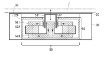
- FIG. 3 is a cross-sectional view of the transducer 50 shown in FIG. 2 cut along a plane passing through the center of the vibration member 511 and parallel to the vibration direction of the vibration member 511.
- a housing 524 that is omitted in FIG. 2 is also illustrated.
- the position of the soundboard 7 is indicated by a two-dot chain line in order to show the positional relationship between the transducer 50 and the soundboard 7.
- the vibration unit 51 includes a vibration member 511 and a voice coil 512.
- the voice coil 512 is disposed so as to be positioned on a magnetic path that passes through a space formed between the yoke 521 and the yoke 523 among magnetic paths (broken arrows) formed by the yokes 521 and 523 and the magnet 522. ing.
- the drive signal input to the transducer 50 is input to the voice coil 512.
- the voice coil 512 receives the magnetic force in the magnetic path formed as described above, and generates a driving force so that the vibrating member 511 vibrates in the vertical direction in the figure according to the waveform indicated by the input driving signal. .
- the housing 524 accommodates the yokes 521 and 523 and the magnet 522.
- the vibration member 511 and the housing 524 are connected by a damper. In the damper, the position where the voice coil 512 is not driven by the vibration signal and no force is applied to the soundboard 7 by the vibration member 511 is set as the standard position. The damper expands and contracts from the standard position following the vertical vibration of the vibration member 511.
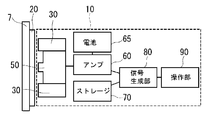
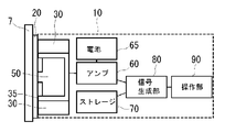
- FIG. 4 is a diagram illustrating a configuration of the vibration supply device 10 and is a view before the vibration supply device 10 is adsorbed to the soundboard 7.
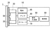
- FIG. 5 is a view after the vibration supply device is adsorbed to the soundboard.
- the iron plate 20 is connected to the soundboard 7 by an adhesive or the like.
- the iron sheet 20 may be formed in a thin and flat seal shape.
- one iron sheet 20 is formed in a circular shape and connected to the outer surface of the soundboard 7.
- the vibration supply apparatus 10 includes a transducer 50, a magnet 30, an amplifier 60, a battery 65, a storage 70, a signal generation unit 80, and an operation unit 90. As illustrated in FIGS. 4 and 5, the transducer 50, the magnet 30, the amplifier 60, the battery 65, the storage 70, the signal generation unit 80, and the operation unit 90 may be housed in one housing. The detailed configuration of the transducer 50 is as described above.
- the storage 70 stores various data including music data.
- the storage 70 includes, for example, an SSD (Solid State Drive), an HDD (Hard Disk Drive), a RAM (Random Access Memory), a ROM (Read Only Memory), or the like.
- the storage 70 stores files related to audio.
- the sound-related file is, for example, a waveform file such as WAV (Waveform Audio File Format) or MP3 (MPEG Audio Layer-3), or a performance data file such as MIDI (Musical Instrument Digital Interface).
- the signal generation unit 80 reads music data from the storage 70, generates a drive signal based on the music data, and supplies the drive signal to the amplifier.
- the waveform information is read, and the sound signal to be output in accordance with the waveform information is output to the amplifier.
- the sound-related file stored in the storage 70 is a performance data file such as MIDI
- the performance data is converted into waveform data by a software synthesizer or the like, and the converted waveform data is output to an amplifier.
- the operation unit 90 serves as a switch for controlling selection of music data to be read out by the signal generation unit 80.
- the switch may be composed of physical operators such as knobs and buttons.
- the switch may be configured with a touch panel that senses input by pressure, capacitance, or the like.
- the amplifier 60 is driven by receiving power from a battery 65 charged by an external power source, amplifies the drive signal transmitted from the signal generation unit 80, transmits the amplified drive signal to the transducer 50, and vibrates.
- the part 51 is vibrated.
- the magnet 30 is disposed outside the transducer 50 and at a position corresponding to the iron sheet 20.
- the magnet 30 may be adhered to the transducer housing with an adhesive or the like. As shown in FIG. 1, the magnet 30 may be provided in a cylindrical shape surrounding the transducer 50.
- the iron sheet 20 and the magnet 30 are attracted and fixed by a magnetic force. Therefore, as shown in FIG. 5, the soundboard 7 of the musical instrument to which the iron sheet 20 is connected and the vibration supply device 10 to which the magnet 30 is connected are attracted and fixed.
- the iron sheet 20 and the magnet 30 are in positions corresponding to each other, that is, positions where the soundboard 7 and the vibration supply device 10 of the musical instrument can be adsorbed and fixed to each other by magnetic force. Placed in.
- the sound of a general (eg, commercially available) musical instrument can be provided without providing an additional attachment mechanism such as a screw or a bolt on the transducer or the musical instrument.
- a transducer can be attached to the plate.
- the vibration member 511 is in a state where the surface where the vibration member 511 is in contact with the iron sheet 20 and the surface where the magnet 30 is in contact with the iron sheet 20 are in the same plane before being attracted to the soundboard 7.
- the vibration member 511 may be disposed so as to protrude from the magnet 30.
- the vibration member 511 of the transducer 50 has the property of vibrating in the vertical direction as shown by the arrow in FIG. When attracted, the portion of the vibrating member 511 that protrudes from the magnet 30 enters the vibrating portion 51 and is pressed against the soundboard 7.
- the degree of contact between the soundboard 7 of the musical instrument and the vibration member 511 of the transducer 50 is adjusted by adjusting the length of the protrusion in a state before being adsorbed by the soundboard 7. And the vibration member 511 can be optimally contacted.
- the contact as used in this application means connecting the vibration from the vibration member 511 to the soundboard 7 so that transmission is possible, and also includes connecting via an iron sheet, a magnet, etc. in between. The same applies to the embodiments described later.
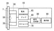
- FIG. 6 is a diagram illustrating a configuration of the second embodiment of the present disclosure.
- the second embodiment of the present disclosure is the same as the first embodiment described above except that the iron sheet 20 is provided on the back surface of the soundboard 7. A description of the same configuration as in the first embodiment is omitted.
- the iron sheet 20 is provided on the back side surface of the soundboard 7 and is attracted by the magnet 30 and magnetic force with the soundboard 7 interposed therebetween.
- the iron sheet 20 is disposed at a position corresponding to the magnet 30.
- the iron sheet 20 may be connected to the back side surface of the soundboard 7 by an adhesive or the like, but without using an adhesive or the like, the iron sheet 20 is adsorbed by a magnetic force with the magnet 30 sandwiching the soundboard 7 to You may fix to the back side surface.
- the vibration supply device can be attached to the instrument without deteriorating the appearance of the instrument.
- the iron sheet 20 and the magnet 30 can be adsorbed by magnetic force with the soundboard 7 interposed therebetween, the musical instrument can be prevented from being damaged by processing the musical instrument itself or adhering an adhesive or the like to the musical instrument.
- the vibration supply device 10 can be attached to the.
- FIG. 7 is a diagram illustrating a configuration of the third embodiment of the present disclosure.
- the third embodiment of the present disclosure is the same as the first embodiment described above except that the metal case 35 is provided. A description of the same configuration as in the first embodiment is omitted.
- the third embodiment of the present disclosure further includes a metal case 35 that surrounds the side and bottom of the transducer 50.
- the magnet 30 can be disposed by being attracted to the outside of the metal case 35.
- the magnet 30 is arrange
- the metal case 35 may be formed in a cylindrical shape that surrounds the entire side and bottom of the transducer 50, or may be formed in a shape that surrounds only a part of the side and bottom of the transducer 50.
- the vibration member 511 that is a portion in contact with the soundboard 7 of the transducer 50 protrudes from the metal case 35 and the magnet 30 before being attracted to the soundboard 7. It may be formed. Since the vibration member 511 of the transducer 50 has the property of vibrating up and down in the direction of the drawing as described above, when the soundboard 7 of the musical instrument and the vibration supply device 10 are adsorbed, the metal case 35 is placed on the vibration member 511. And the part which protruded from the magnet 30 enters the inside of the vibration part 51, and is pressed against the soundboard 7.
- the magnet 30 can be easily attached to the transducer 50 in the third embodiment of the present disclosure. Further, since the positioning of the magnet 30 is facilitated, the length of the protrusion of the vibration member 511 is adjusted, the degree of contact between the soundboard 7 of the musical instrument and the vibration member 511 of the transducer 50 is adjusted, It becomes easier to achieve optimal contact with the vibration member 511.
- FIG. 8 is a diagram illustrating a configuration of the fourth embodiment of the present disclosure.
- the fourth embodiment of the present disclosure is the same as the first embodiment described above except that it further includes a stand 600 on which a musical instrument is arranged. A description of the same configuration as in the first embodiment is omitted.
- the vibration supply device 10 can be detached from the stand while being attached to the outer surface of the soundboard 7 of the musical instrument 1.
- the stand 600 included in the musical instrument of the fourth embodiment of the present disclosure includes a power supply unit 630 that inputs power from the external power source 610 to the vibration supply device 10, and the vibration supply device 10 includes the power supply unit of the stand 600.
- a power receiving unit 640 that receives an input from the external power source 610 from 630 is provided.
- the vibration supply apparatus 10 may be provided with a rechargeable battery, and the rechargeable battery may be charged by inputting the external power supply 610 to the rechargeable battery through the power supply unit 630 of the stand.
- the rechargeable battery of the vibration supply device 10 attached to the musical instrument can be charged while the musical instrument 1 is leaned, so that the musical instrument 1 with the vibration supply device 10 attached can be used as a stand. It can also be used as a speaker in a state where it is detached from 600.
- the stand 600 included in the musical instrument according to the fourth embodiment of the present disclosure includes a data supply unit 650 for supplying data from the data server 620 to the storage 70 of the vibration supply device 10. Includes a data receiving unit 660 that receives data input from the data supply unit 650 of the stand 600.
- the data server 620 may store and manage a plurality of pieces of music data that are the basis of the drive signal supplied to the musical instrument. By having such a configuration, a large amount of music data stored in the data server 620 can be supplied to the vibration supply device 10, so that more music can be obtained using the soundboard 7 of the musical instrument 1. Can be reproduced.
- FIG. 9 is a diagram illustrating a configuration of the fifth embodiment of the present disclosure.
- the fifth embodiment of the present disclosure is the same as the above-described embodiment except that a communication unit 75 is provided instead of the storage 70. A description of the same configuration as that of the above-described embodiment is omitted.
- a communication unit 75 is provided instead of the storage 70.
- the communication unit 75 may be configured to receive provision of various data through an electric communication line or the like from an external device in which various data including music data is stored and stored.
- the communication unit 75 may be, for example, Bluetooth (registered trademark).
- the external device may be, for example, a music player or a terminal such as a smartphone or a tablet.
- the signal generation unit 80 reads music data from the communication unit 75, generates a drive signal based on the music data, and supplies the drive signal to the amplifier.
- the operation unit 90 serves as a switch for controlling selection of music data to be read out by the signal generation unit 80.
- the amplifier 60 is driven by receiving power from the battery 65 charged by an external power source, amplifies the drive signal provided from the signal generation unit 80 and provides the amplified signal to the transducer 50, and vibrates the vibration unit 51.
- the vibration supply device 10 it is not necessary to provide a storage for storing and storing music data, and vibration can be easily supplied by operating an external device. Music data can be provided to the device.
- FIG. 10 is a diagram illustrating a configuration of the sixth embodiment of the present disclosure.
- the sixth embodiment of the present disclosure is the same as the above-described embodiment except that a vibrator-type transducer is used as the transducer of the vibration supply device 10. A description of the same configuration as that of the above-described embodiment is omitted.
- the transducer 50b is not a voice coil type transducer but a vibrator type transducer.
- the vibrator-type transducer here refers to a vibrator that vibrates the entire main body by vibrating a vibrating member inside the main body, like the vibration function of a mobile phone.
- the vibration supply device 10 may be attached to the musical instrument as described above, and as shown in FIG. 10, the surface of the transducer 50 b that contacts the soundboard 7 has a sheet shape.
- the iron sheet 20 and the magnet 30b are attracted and fixed by a magnetic force, so that the iron sheet 20 is connected.
- the soundboard 7 and the vibration supply device 10 to which the magnet 30b is connected may be attracted and fixed.
- the iron sheet 20 may be other soft magnetic materials.
- the soft magnetic material containing iron may have any shape as long as it is attracted by the magnet 30 connected to the transducer 50 and magnetic force, and may be, for example, a polygonal shape other than the circular shape.
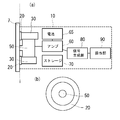
- FIG. 11 (a) a donut shape in which a circular middle portion is cut out may be used.
- FIG. 11B is a view of FIG. 11A taken along the dotted line i and viewed from the soundboard 7 side from the vibration supply device 10 side. As shown in FIG.
- a soft magnetic material containing iron is provided between the soundboard and the transducer 50 by forming a soft magnetic material containing iron into a donut shape in which a circular middle portion is hollowed out. It is possible to prevent deterioration of sound quality due to. Further, the number of soft magnetic materials including iron may not be one, and two or more may be provided. The position where the soft magnetic material containing iron is arranged may be arranged in any way as long as it is a position attracted by the magnet 30 and the magnetic force.
- the magnet 30 may be another hard magnetic material.
- the hard magnetic material including the magnet may have any shape as long as it is attracted by the magnetic force with the iron sheet 20 connected to the soundboard 7. It may be a prismatic shape. Further, the number of hard magnetic materials including magnets may not be one, and two or more may be provided. The hard magnetic material including the magnet may be disposed in any position as long as it is a position that is attracted by the soft magnetic material including iron and the magnetic force.
- a hard magnetic material including a magnet may be connected to the soundboard 7 of the musical instrument, and the vibration supply device 10 may include a soft magnetic material including iron.
- the hard magnetic material including the magnet and the soft magnetic material including iron may be connected to the soundboard 7 and the transducer 50 of the musical instrument by an adhesive or the like, respectively. They may be adsorbed and fixed to each other.
- the housing 524 of the transducer 50 may be made of a soft magnetic material containing iron. In such a configuration, the step of connecting the soft magnetic material containing iron to the transducer 50 is omitted or It can be simplified.
- both the soundboard 7 of the musical instrument and the vibration supply device 10 may be provided with a hard magnetic material including a magnet.
- the hard magnetic material including the magnet may be connected to the soundboard 7 and the transducer 50 of the musical instrument by an adhesive or the like, respectively, and is attracted and fixed to each other with the soundboard interposed therebetween. May be.
- a metal case may be disposed outside the transducer 50 and may be adsorbed and fixed to the metal case.
- the vibration supply device 10 and the soundboard 7 of the musical instrument can be adsorbed and fixed by magnetic force.
- the amplifier 60 may be driven by receiving power from a dry battery or the like in addition to an internal rechargeable battery charged by an external power source. Moreover, in the vibration supply apparatus 10, you may further provide the mechanism which arrange
- ⁇ Modification of musical instrument 1> In the embodiment described above, the case where the musical instrument is an acoustic guitar has been shown. However, the present disclosure is not limited to this, and a stringed musical instrument having a sound board that transmits vibrations of strings such as a bass, a violin, a ukulele, a mandolin, and a piano. It is possible to apply. The present disclosure can be applied not only to stringed instruments but also to percussion instruments having a cajon soundboard.
- the vibration supply device of the present disclosure includes a transducer having a vibration member, and a second member that is attracted by a magnetic force to a first member connected to a soundboard of the musical instrument, and the vibration member includes the first member When the member and the second member are adsorbed to each other, they are connected to transmit vibration to the soundboard.
- the second member is disposed outside the transducer.
- the vibration supply device includes a storage that stores data, a signal generation unit that reads out data stored in the storage and generates an audio signal, and an amplifier that amplifies the audio signal and drives the vibration member Are further included.
- the driving unit includes a power receiving unit that receives power from the outside and a data receiving unit that receives data to be stored in the storage from the outside.
- the power receiving unit receives power from a stand on which the musical instrument is placed, and the data receiving unit receives data to be stored in the storage from the stand.
- the vibration supply device further includes a metal case surrounding at least one of a side portion and a bottom portion of the transducer, The second member is disposed outside the metal case.
- the musical instrument of the present disclosure includes the vibration supply device, a soundboard, and a first member that is disposed at a position corresponding to the second member and connected to the soundboard.
- the first member and the second member come into contact with each other and are attracted to each other.
- the first member and the second member are adsorbed to each other across a soundboard.
- the first member has a sheet shape.
- the vibration supply device of the present disclosure is useful because the vibration supply device and the soundboard of the musical instrument can be adsorbed and fixed by magnetic force.
Landscapes
- Engineering & Computer Science (AREA)
- Physics & Mathematics (AREA)
- Acoustics & Sound (AREA)
- Signal Processing (AREA)
- Multimedia (AREA)
- Electrophonic Musical Instruments (AREA)
- Details Of Audible-Bandwidth Transducers (AREA)
- Circuit For Audible Band Transducer (AREA)
- Diaphragms For Electromechanical Transducers (AREA)
Abstract
振動供給装置(10)は、振動部材(511)を有するトランスデューサー(50,50b)と、楽器(1)の響板(7)に接続される第1部材(20)に磁力によって吸着される第2部材(30)と、を有する。前記振動部材は、前記第1部材(20)と前記第2部材(30)とが互いに吸着されると前記響板(7)へ振動を伝達するように接続される。
Description
本開示は、楽器に振動供給装置を取り付ける技術に関する。
従来、アコースティックのギター、ベース、バイオリン、ウクレレ、マンドリン等、響板を含む共鳴胴を有する楽器が知られている。例えばギターの共鳴胴は、表板、裏板及び側板から構成され、表板にはサウンドホールが形成される。弦の演奏により主として響板たる表板及び裏板が振動して豊かな音響が発生する。
このような響板により生成される豊かな音響は、コーン紙を振動させる通常のスピーカーシステムで再現することが難しい。そのため、演奏によらずに、このような楽器そのものの響板を利用して音響を発生させる装置が知られている。例えば、楽器そのものをスピーカーとして用い、その響板にねじでトランスデューサーを取り付け、その振動を楽器の胴部に伝え、音響振動を発する技術が知られている(例えば、特許文献1)。ボルトを用いて楽器にトランスデューサーを取り付ける方法(例えば、特許文献2)も知られている。
しかしながら、特許文献1ないし2の技術では、ねじやボルトによる取り付け機構をトランスデューサー及び楽器の双方に設ける必要があり、トランスデューサー及び楽器を変形させなくてはならず、一般の(例えば、市販の)ギター等に広く適用できるものではない。
また、特許文献1ないし2の技術では、トランスデューサーを楽器の裏板にネジやボルトで取り付ける必要があるため、ユーザが楽器をスピーカーとして使用する場面と、トランスデューサーを外して楽器を演奏する場面とを切り替えるのに手間がかかるという問題があった。
そこで、本開示は、一般の楽器の響板を利用して楽器本来の音色を再現させるための、楽器へのトランスデューサーの着脱を容易にすることを目的の1つとする。
上記課題を解決するために本開示の振動供給装置は、振動部材を有するトランスデューサーと、楽器の響板に接続される第1部材に磁力によって吸着される第2部材と、を有し、前記振動部材は、前記第1部材と前記第2部材とが互いに吸着されると前記響板へ振動を伝達するように接続される。
また、本開示の楽器は、前記振動供給装置と、響板と、前記第2部材に対応する位置に配置され、前記響板に接続される第1部材と、を有する。
また、本開示の楽器は、前記振動供給装置と、響板と、前記第2部材に対応する位置に配置され、前記響板に接続される第1部材と、を有する。
本開示によれば、一般の楽器の響板を利用して楽器本来の音色を再現させるための、楽器へのトランスデューサーの着脱を容易にすることができる。
以下、本開示の一実施形態の楽器について、図面を参照しながら詳細に説明する。以下に示す実施形態は本開示の実施形態の一例であって、本開示はこれらの実施形態に限定されるものではない。
<第1実施形態>
本開示の第1実施形態の楽器について、図面を参照しながら詳細に説明する。
本開示の第1実施形態の楽器について、図面を参照しながら詳細に説明する。
図1は、本開示の第1実施形態の振動供給装置10が楽器に取り付けられた状態を示す図である。
振動供給装置10は、響板7に接続された鉄シート20と、振動供給装置10に接続された磁石30が磁力によって吸着されることで、楽器1の響板7の外側表面に取り付けられる。取付け方の詳細については後に説明する。図1で楽器1には振動供給装置10が1個取り付けられているが、その取り付け個数は2個以上であってもよい。また、図1では楽器の裏板に振動供給装置10が取り付けられている例を示したが、振動供給装置10は楽器の表板に取り付けられてもよい。
[トランスデューサーの構成]
図2は、振動供給装置10に含まれるトランスデューサー50の外観を示した図である。この図においては、ヨーク保持部52の主要な構造を見やすくするため、ヨーク保持部52の筐体524(図3参照)については記載を省略し、筐体524の内部を図示している。
図2は、振動供給装置10に含まれるトランスデューサー50の外観を示した図である。この図においては、ヨーク保持部52の主要な構造を見やすくするため、ヨーク保持部52の筐体524(図3参照)については記載を省略し、筐体524の内部を図示している。
振動部51は、響板7(図3参照)と接続する上面が塞がれた筒状の振動部材511およびボイスコイル512を有する。振動部材511は、ポリイミド等の樹脂あるいはアルミ素材の金属などの素材で形成され、上面部に樹脂等のキャップを取り付けている。振動部材511の先端には、磁石が配置されてもよく、この磁石は粘着材等によって振動部材511の先端に接着されてもよい。ヨーク保持部52は、磁石522、および磁石522を挟みこむヨーク521、523を有する。ヨーク521、523は、例えば軟鉄などの軟磁性材料により形成される。また、振動部51とヨーク保持部52とは、空間により隔てられている。
図3は、図2に示すトランスデューサー50を振動部材511の中心を通り、振動部材511の振動方向に平行な面で切断した断面図である。図3においては、図2において記載を省略した筐体524についても記載している。また、図3においては、トランスデューサー50と響板7の位置関係を示すため、響板7の位置を2点鎖線で示している。
振動部51は、振動部材511およびボイスコイル512を有している。ボイスコイル512は、ヨーク521、523および磁石522により形成された磁路(破線矢印)のうち、ヨーク521とヨーク523との間に形成される空間を通過する磁路上に位置するように配置されている。トランスデューサー50に入力される駆動信号は、ボイスコイル512に入力される。ボイスコイル512は、上記のように形成されている磁路における磁力を受けて、入力される駆動信号が示す波形に応じて振動部材511が図における上下方向に振動するように駆動力を発生させる。そして、以下で詳述する方法によってトランスデューサー50と響板7とが吸着され、振動部材511における振動が響板7に伝達される。筐体524は、ヨーク521、523および磁石522を収容する。図示はしていないが、振動部材511と筐体524とはダンパによって接続される。ダンパは、ボイスコイル512が振動信号により駆動されず、振動部材511による響板7に対する力がかからない状態での位置を標準位置とする。ダンパは、この標準位置から、振動部材511の上下振動に追従して伸縮する。
[振動供給装置の構成]
図4は振動供給装置10の構成を示した図であり、振動供給装置10が響板7に吸着される前の図である。図5は、振動供給装置が響板に吸着された後の図である。
図4は振動供給装置10の構成を示した図であり、振動供給装置10が響板7に吸着される前の図である。図5は、振動供給装置が響板に吸着された後の図である。
本開示の第1実施形態において、響板7には粘着剤等によって鉄シート20が接続される。鉄シート20は薄くて平らなシール状に形成されてもよい。図1においては1個の鉄シート20が円形に形成され、響板7の外側表面に接続されている。
振動供給装置10は、トランスデューサー50、磁石30、アンプ60、電池65、ストレージ70、信号生成部80、及び操作部90を有する。図4や図5に示したとおり、トランスデューサー50、磁石30、アンプ60、電池65、ストレージ70、信号生成部80、及び操作部90は、1つの筐体に収められていてもよい。トランスデューサー50の詳しい構成については前述したとおりである。
ストレージ70は、楽曲データを含む各種データを記憶する。ストレージ70は、例えば、SSD(Solid State Drive)、HDD(Hard Disk Drive)、RAM(Random Access Memory)、又はROM(Read Only Memory)等によって構成される。ストレージ70には、音声に関連するファイルが記憶されている。ここで、音声に関連するファイルとは、例えば、WAV(Waveform Audio File Format)やMP3(MPEG Audio Layer-3)等の波形ファイルや、MIDI(Musical Instrument Digital Interface)等の演奏データファイルである。
信号生成部80は、ストレージ70から楽曲データを読み出して、楽曲データに基づいて駆動信号を生成してアンプへ供給する。具体的には、ストレージ70に記憶された音声に関するファイルが波形ファイルの場合は、まず波形の情報を読み出し、該波形の情報に合わせて出力すべき音声信号をアンプに出力する。ストレージ70に記憶された音声に関するファイルがMIDI等の演奏データファイルの場合は、当該演奏データをソフトウェアシンセサイザー等により波形データへと変換し、該変換した波形データをアンプに出力する。
操作部90は信号生成部80において読み出す楽曲データの選択などを制御するスイッチの役割を有する。当該スイッチは、ノブやボタン等の物理操作子で構成されてもよい。また、当該スイッチは、圧力や静電容量等により入力を感知するタッチパネルで構成されてもよい。アンプ60は、外部電源によって充電される電池65から電力の提供を受けて駆動し、信号生成部80から送信された駆動信号を増幅し、増幅された駆動信号をトランスデューサー50へ送信し、振動部51を振動させる。
信号生成部80は、ストレージ70から楽曲データを読み出して、楽曲データに基づいて駆動信号を生成してアンプへ供給する。具体的には、ストレージ70に記憶された音声に関するファイルが波形ファイルの場合は、まず波形の情報を読み出し、該波形の情報に合わせて出力すべき音声信号をアンプに出力する。ストレージ70に記憶された音声に関するファイルがMIDI等の演奏データファイルの場合は、当該演奏データをソフトウェアシンセサイザー等により波形データへと変換し、該変換した波形データをアンプに出力する。
操作部90は信号生成部80において読み出す楽曲データの選択などを制御するスイッチの役割を有する。当該スイッチは、ノブやボタン等の物理操作子で構成されてもよい。また、当該スイッチは、圧力や静電容量等により入力を感知するタッチパネルで構成されてもよい。アンプ60は、外部電源によって充電される電池65から電力の提供を受けて駆動し、信号生成部80から送信された駆動信号を増幅し、増幅された駆動信号をトランスデューサー50へ送信し、振動部51を振動させる。
磁石30は、トランスデューサー50の外側であって、鉄シート20に対応する位置に配置される。磁石30は粘着剤等によってトランスデューサーの筐体へ接着されてもよい。図1に示したように、磁石30は、トランスデューサー50を囲む円筒状に設けられてもよい。
このとき、鉄シート20と磁石30とは磁力によって吸着され、固定される。それゆえ、図5に示したように、鉄シート20が接続された楽器の響板7と、磁石30が接続された振動供給装置10とが吸着され、固定される。
このようにして、信号生成部80によって生成された駆動信号に基づく振動が振動部材511を通じて楽器の響板7へと伝達され、響板7を利用した音響の発生が可能となる。このような構成を実現するため、鉄シート20と磁石30とは、互いに対応する位置、すなわち、楽器の響板7と振動供給装置10とが磁力によって互いに吸着し、固定することが可能な位置に配置される。
このような構成を有することで、本開示の第1実施形態においては、ねじやボルト等の追加的な取り付け機構をトランスデューサーや楽器に設けることなく、一般の(例えば、市販の)楽器の響板にトランスデューサーを取り付けることが可能となる。また、本開示の第1実施形態によれば、ネジやボルトで取り付ける過程を要さず、所望の位置に振動供給装置を近づけるのみで振動供給装置を楽器の響板へ固定することが可能になるため、ユーザが楽器をスピーカーとして使用する場面と、振動供給装置を外して楽器を演奏する場面とを容易かつ迅速に切り替えることができる。
図3に示した例では、振動部材511は、響板7に吸着される前の状態において、振動部材511が鉄シート20と接する面と、磁石30が鉄シート20と接する面とが同一平面上に配置されているが、必ずしも同一平面上に配置されなくてもよい。例えば、振動部材511が磁石30よりも突出するように配置されてもよい。このような配置の場合、前記のとおり、トランスデューサー50の振動部材511は図3の矢印で示されるように上下方向に振動する性質を有するため、楽器の響板7と振動供給装置10とが吸着されると、振動部材511において磁石30より突出していた部分は振動部51の内部に入り込み、響板7に押し当てられる。
このとき、響板7に吸着される前の状態において、突出の長さを調整することで、楽器の響板7とトランスデューサー50の振動部材511との接触の度合いを調整し、響板7と振動部材511との間の最適な接触を実現することが可能となる。なお、本願でいう接触とは、振動部材511から響板7への振動を伝達可能に接続させることを言い、間に鉄シートや磁石などを介して接続されることも含む。後述する実施例についても同様である。
<第2実施形態>
図6は、本開示の第2実施形態の構成を示した図である。本開示の第2実施形態は、鉄シート20が響板7の裏側表面に備えられていることを除いては、上述した第1実施形態と同様である。第1実施形態と同様の構成についての記載は省略する。
図6は、本開示の第2実施形態の構成を示した図である。本開示の第2実施形態は、鉄シート20が響板7の裏側表面に備えられていることを除いては、上述した第1実施形態と同様である。第1実施形態と同様の構成についての記載は省略する。
図6に示したように、本開示の第2実施形態においては、鉄シート20は響板7の裏側表面に設けられ、響板7を挟んで磁石30と磁力によって吸着される。鉄シート20は、磁石30に対応する位置に配置される。鉄シート20は粘着剤等によって響板7の裏側表面に接続されてもよいが、粘着剤等を使用することなく、響板を挟んだ磁石30との磁力によって吸着させることで響板7の裏側表面に固定してもよい。
このように、本開示の第2実施形態においては、鉄シート20が響板7の裏側表面に備えられるので、楽器の外観を損なうことなく振動供給装置を楽器に取り付けることが可能となる。また、鉄シート20と磁石30とを響板7を挟んで磁力によって吸着させることができるので、楽器自体を加工したり、楽器に粘着剤等を接着することによる楽器への損傷を防ぎつつ楽器に振動供給装置10を取り付けることができる。
<第3実施形態>
図7は、本開示の第3実施形態の構成を示した図である。本開示の第3実施形態は、金属ケース35が備えられていることを除いては、上述した第1実施形態と同様である。第1実施形態と同様の構成についての記載は省略する。
図7は、本開示の第3実施形態の構成を示した図である。本開示の第3実施形態は、金属ケース35が備えられていることを除いては、上述した第1実施形態と同様である。第1実施形態と同様の構成についての記載は省略する。
図7に示したとおり、本開示の第3実施形態においては、トランスデューサー50の側部及び底部を囲む金属ケース35をさらに備える。この場合、磁石30は、金属ケース35の外側に吸着させて配置することができる。本開示の第3実施形態においても、磁石30は鉄シート20に対応する位置に配置されて、磁力によって、鉄シート20と吸着されるようにする。
金属ケース35は、トランスデューサー50の側部及び底部の全部を囲む円筒形状で形成されてもよいし、トランスデューサー50の側部及び底部の一部分のみを囲む形状で形成されてもよい。
本開示の第3実施形態においては、トランスデューサー50のうち響板7に接する部分である振動部材511は、響板7に吸着される前の状態において、金属ケース35及び磁石30より突出するように形成されていてもよい。トランスデューサー50の振動部材511は、前述のとおり、図面の方向において上下に振動する性質を有するため、楽器の響板7と振動供給装置10とが吸着されると、振動部材511において金属ケース35及び磁石30より突出していた部分は振動部51の内部に入り込み、響板7に押し当てられる。
このような構成を有することで、本開示の第3実施形態においては、磁石30を容易にトランスデューサー50へ取り付けることができる。さらに、磁石30の位置決めが容易となるので、振動部材511の突出の長さの調整し、楽器の響板7とトランスデューサー50の振動部材511との接触の度合いを調整し、響板7と振動部材511との間の最適な接触を実現することがより容易となる。
<第4実施形態>
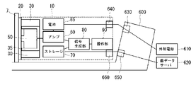
図8は、本開示の第4実施形態の構成を示した図である。本開示の第4実施形態は、楽器を配置するスタンド600をさらに有することを除いては、上述した第1実施形態と同様である。第1実施形態と同様の構成についての記載は省略する。なお振動供給装置10は楽器1の響板7の外側表面に取り付けられたまま、スタンドからの取り外しが可能である。
図8は、本開示の第4実施形態の構成を示した図である。本開示の第4実施形態は、楽器を配置するスタンド600をさらに有することを除いては、上述した第1実施形態と同様である。第1実施形態と同様の構成についての記載は省略する。なお振動供給装置10は楽器1の響板7の外側表面に取り付けられたまま、スタンドからの取り外しが可能である。
本開示の第4実施形態の楽器に備えられるスタンド600は、振動供給装置10に外部電源610からの電力を入力する電源供給部630を有し、振動供給装置10は、スタンド600の電源供給部630から外部電源610の入力を受ける電源受容部640を有する。振動供給装置10に充電池を備えて、スタンドの電源供給部630を通じて外部電源610を充電池に入力することで、充電池を充電させてもよい。
このような構成を有することにより、楽器1を立て掛けている間に楽器に取り付けられた振動供給装置10の充電池を充電させておけるので、振動供給装置10を取り付けた状態の楽器1を、スタンド600から取り外した状態で、スピーカーとして使用することも可能となる。
また、本開示の第4実施形態の楽器に備えられるスタンド600は、データサーバ620からのデータを振動供給装置10のストレージ70に供給するための、データ供給部650を有し、振動供給装置10は、スタンド600のデータ供給部650からデータの入力を受けるデータ受信部660を有する。
データサーバ620には、楽器に供給する駆動信号の基となる複数の楽曲データを保存・管理しておいてもよい。このような構成を有することにより、データサーバ620に保存しておいた大量の楽曲データを振動供給装置10へ供給することができるので、より多くの楽曲を楽器1の響板7を利用して再現することができる。
<第5実施形態>
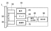
図9は、本開示の第5実施形態の構成を示した図である。本開示の第5実施形態は、ストレージ70の代わりに通信部75を設けることを除いては、上述した実施形態と同様である。上述した実施形態と同様の構成についての記載は省略する。
図9は、本開示の第5実施形態の構成を示した図である。本開示の第5実施形態は、ストレージ70の代わりに通信部75を設けることを除いては、上述した実施形態と同様である。上述した実施形態と同様の構成についての記載は省略する。
本開示の第5実施形態の振動供給装置10においては、ストレージ70の代わりに通信部75が設けられる。通信部75は、楽曲データを含む各種データが保管記憶された外部機器から電気通信回線等を通じて各種データの提供を受けるように構成されてもよい。通信部75は、例えば、Bluetooth(登録商標)であってもよい。外部機器は、例えば、音楽プレーヤーであってもよいし、スマートフォンやタブレット等の端末であってもよい。
本開示の第5実施形態の振動供給装置10において、信号生成部80は、通信部75から楽曲データを読み出して、楽曲データに基づいて駆動信号を生成してアンプへ供給する。操作部90は信号生成部80において読み出す楽曲データの選択などを制御するスイッチの役割を有する。アンプ60は、外部電源によって充電される電池65から電力の提供を受けて駆動し、信号生成部80から提供された駆動信号を増幅してトランスデューサー50へ提供し、振動部51を振動させる。
このような構成を有することによって、本開示の第5実施形態の振動供給装置10においては、楽曲データを保管記憶しておくストレージを設ける必要がなくなり、外部機器を操作することによって容易に振動供給装置に楽曲データを提供することができる。
<第6実施形態>
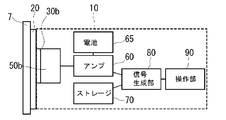
図10は、本開示の第6実施形態の構成を示した図である。本開示の第6実施形態は、振動供給装置10のトランスデューサーとしてバイブレータ型のトランスデューサーを用いることを除いては、上述した実施形態と同様である。上述した実施形態と同様の構成についての記載は省略する。
図10は、本開示の第6実施形態の構成を示した図である。本開示の第6実施形態は、振動供給装置10のトランスデューサーとしてバイブレータ型のトランスデューサーを用いることを除いては、上述した実施形態と同様である。上述した実施形態と同様の構成についての記載は省略する。
図10に示したように、本開示の第6実施形態のトランスデューサー50bは、ボイスコイル型のトランスデューサーではなく、バイブレータ型のトランスデューサーである。ここでいうバイブレータ型のトランスデューサーとは、携帯電話のバイブレーション機能のように、本体内部で振動部材を振動させることで本体全体を振動させるものをいう。
本開示の第6実施形態においても上述したように振動供給装置10を楽器へ取り付けてもよいし、図10に示したように、トランスデューサー50bの、響板7に接触する面にシート状の磁石30bを接続し、響板7の外側表面に鉄シート20を接続することで、鉄シート20と磁石30bとが磁力によって吸着され、固定されるようにし、鉄シート20が接続された楽器の響板7と、磁石30bが接続された振動供給装置10とが吸着され、固定されるようにしてもよい。
<鉄シート20及び磁石30の変形例>
本開示の他の実施形態において、鉄シート20は、他の軟磁性材料であってもよい。鉄を含む軟磁性材料は、トランスデューサー50に接続された磁石30と磁力によって吸着される形状であればどのような形状であってもよく、円形状以外に、例えば多角形状であってもよいし、図11(a)に示したように円形の真ん中部分をくり抜いたドーナッツ形状であってもよい。図11(b)は、図11(a)を点線iで切って響板7側から振動供給装置10側を見た図である。図11(b)に示したように鉄を含む軟磁性材料を円形の真ん中部分をくり抜いたドーナッツ形状にすることで、響板とトランスデューサー50との間に鉄を含む軟磁性材料を設けることによる音質の低下を防止することができる。また、鉄を含む軟磁性材料の個数は1個でなくてもよく、2個以上設けてもよい。鉄を含む軟磁性材料を配置する位置は、磁石30と磁力によって吸着される位置であればどのように配置してもよい。
本開示の他の実施形態において、鉄シート20は、他の軟磁性材料であってもよい。鉄を含む軟磁性材料は、トランスデューサー50に接続された磁石30と磁力によって吸着される形状であればどのような形状であってもよく、円形状以外に、例えば多角形状であってもよいし、図11(a)に示したように円形の真ん中部分をくり抜いたドーナッツ形状であってもよい。図11(b)は、図11(a)を点線iで切って響板7側から振動供給装置10側を見た図である。図11(b)に示したように鉄を含む軟磁性材料を円形の真ん中部分をくり抜いたドーナッツ形状にすることで、響板とトランスデューサー50との間に鉄を含む軟磁性材料を設けることによる音質の低下を防止することができる。また、鉄を含む軟磁性材料の個数は1個でなくてもよく、2個以上設けてもよい。鉄を含む軟磁性材料を配置する位置は、磁石30と磁力によって吸着される位置であればどのように配置してもよい。
また、本開示の他の実施形態において、磁石30は、他の硬磁性材料であってもよい。磁石を含む硬磁性材料は、響板7に接続された鉄シート20と磁力によって吸着される形状であればどのような形状であってもよく、トランスデューサー50を囲む円筒状以外に、例えば四角柱の形状であってもよい。また、磁石を含む硬磁性材料の個数は1個でなくてもよく、2個以上設けてもよい。磁石を含む硬磁性材料を配置する位置は、鉄を含む軟磁性材料と磁力によって吸着される位置であればどのように配置してもよい。
さらに、本開示の他の実施形態においては、楽器の響板7に磁石を含む硬磁性材料を接続し、振動供給装置10に鉄を含む軟磁性材料を備えてもよい。この場合も上記した実施形態と同様に、磁石を含む硬磁性材料及び鉄を含む軟磁性材料は、粘着剤等によってそれぞれ楽器の響板7及びトランスデューサー50に接続されてもよいし、響板を挟んで互いに吸着され固定されてもよい。このとき、トランスデューサー50の筐体524は鉄を含む軟磁性材料で構成されていてもよく、そのような構成にする場合、トランスデューサー50に鉄を含む軟磁性材料を接続する工程を省略または簡略化することができる。
また、楽器の響板7、及び、振動供給装置10の双方に磁石を含む硬磁性材料を備えてもよい。この場合も上記した実施形態と同様に、磁石を含む硬磁性材料は、粘着剤等によってそれぞれ楽器の響板7及びトランスデューサー50に接続されてもよいし、響板を挟んで互いに吸着され固定されてもよい。また、振動供給装置10においては、トランスデューサー50の外側に金属ケースを配置して、金属ケースに吸着させて固定させてもよい。
このように、楽器の響板7側、及び振動供給装置10側のうち少なくとも一方を磁石にすることによって、振動供給装置10と楽器の響板7とを磁力によって吸着させ、固定させることができる。
<電池65の変形例>
本開示の他の実施形態において、アンプ60は、外部電源によって充電される内部の充電池の他に、乾電池等によって電力の提供を受けて駆動させてもよい。また、振動供給装置10において、充電池や乾電池を着脱可能なように配置する機構をさらに設けてもよい。
本開示の他の実施形態において、アンプ60は、外部電源によって充電される内部の充電池の他に、乾電池等によって電力の提供を受けて駆動させてもよい。また、振動供給装置10において、充電池や乾電池を着脱可能なように配置する機構をさらに設けてもよい。
<楽器1の変形例>
上述した実施形態では、楽器がアコースティックギターである場合を示したが、本開示はこれに限られず、ベース、バイオリン、ウクレレ、マンドリン、ピアノ等弦の振動が伝達される響板を有する弦楽器であれば適用することが可能である。なお、本開示は、弦楽器に限らず、カホン等響板を有する打楽器にも適用することが可能である。
上述した実施形態では、楽器がアコースティックギターである場合を示したが、本開示はこれに限られず、ベース、バイオリン、ウクレレ、マンドリン、ピアノ等弦の振動が伝達される響板を有する弦楽器であれば適用することが可能である。なお、本開示は、弦楽器に限らず、カホン等響板を有する打楽器にも適用することが可能である。
ここで、本開示の実施形態を以下のようにまとめる。
本開示の振動供給装置は、振動部材を有するトランスデューサーと、楽器の響板に接続される第1部材に磁力によって吸着される第2部材と、を有し、前記振動部材は、前記第1部材と前記第2部材とが互いに吸着されると前記響板へ振動を伝達するように接続される。
本開示の振動供給装置は、振動部材を有するトランスデューサーと、楽器の響板に接続される第1部材に磁力によって吸着される第2部材と、を有し、前記振動部材は、前記第1部材と前記第2部材とが互いに吸着されると前記響板へ振動を伝達するように接続される。
例えば、前記第2部材は、前記トランスデューサーの外側に配置されている。
例えば、前記振動供給装置は、データを記憶するストレージと、前記ストレージに記憶されたデータを読み出して音声信号を生成する信号生成部と、前記音声信号を増幅して前記振動部材を駆動するアンプと、を備える駆動ユニットをさらに有する。
例えば、前記駆動ユニットは、外部から電力の供給を受ける電源受容部と、前記外部から前記ストレージに記憶させるデータの供給を受けるデータ受信部と、を備える。
例えば、前記電源受容部は、前記楽器を配置するスタンドから電力の供給を受け、前記データ受信部は、前記スタンドから前記ストレージに記憶させるデータの供給を受ける
例えば、前記振動供給装置は、前記トランスデューサーの側部及び底部の少なくとも一方を囲む金属ケースをさらに備え、
前記第2部材は、前記金属ケースの外側に配置される。
前記第2部材は、前記金属ケースの外側に配置される。
また、本開示の楽器は、前記振動供給装置と、響板と、前記第2部材に対応する位置に配置され、前記響板に接続される第1部材と、を有する。
例えば、前記楽器において、前記第1部材と前記第2部材とが接触して互いに吸着される。
例えば、前記楽器において、前記第1部材と前記第2部材とが響板を挟んで互いに吸着される。
例えば、前記楽器において、前記第1部材はシート状である。
本出願は、2015年3月25日に出願された日本特許出願(特願2015-062501)に基づくものであり、ここに参照として取り込まれる。
本開示の振動供給装置によれば、振動供給装置と楽器の響板とを磁力によって吸着させ、固定させることができるため有用である。
1…楽器、7…響板、10…振動供給装置、20…鉄シート、30、30b…磁石、35…金属ケース、50、50b…トランスデューサー、51…振動部、52…ヨーク保持部、60…アンプ、65…電池、70…ストレージ、75…通信部、80…信号生成部、90…操作部、511…振動部材、512…ボイスコイル、522…磁石、521、523…ヨーク、524…筐体、600…スタンド、 610…外部電源、 620…データサーバ、630…電源供給部、640…電源受容部、650…データ供給部、660…データ受信部
Claims (10)
- 振動部材を有するトランスデューサーと、
楽器の響板に接続される第1部材に磁力によって吸着される第2部材と、
を有し、
前記振動部材は、前記第1部材と前記第2部材とが互いに吸着されると前記響板へ振動を伝達するように接続されることを特徴とする振動供給装置。 - 前記第2部材は、前記トランスデューサーの外側に配置されていることを特徴とする請求項1に記載の振動供給装置。
- データを記憶するストレージと、前記ストレージに記憶されたデータを読み出して音声信号を生成する信号生成部と、前記音声信号を増幅して前記振動部材を駆動するアンプと、を備える駆動ユニットをさらに有することを特徴とする請求項1又は2に記載の振動供給装置。
- 前記駆動ユニットは、外部から電力の供給を受ける電源受容部と、前記外部から前記ストレージに記憶させるデータの供給を受けるデータ受信部と、を備えることを特徴とする請求項3に記載の振動供給装置。
- 前記電源受容部は、前記楽器を配置するスタンドから電力の供給を受け、前記データ受信部は、前記スタンドから前記ストレージに記憶させるデータの供給を受けることを特徴とする請求項4に記載の振動供給装置。
- 前記トランスデューサーの側部及び底部の少なくとも一方を囲む金属ケースをさらに備え、
前記第2部材は、前記金属ケースの外側に配置されることを特徴とする請求項1乃至5のいずれか一項に記載の振動供給装置。 - 請求項1乃至6のいずれか一項に記載の振動供給装置と、
響板と、
前記第2部材に対応する位置に配置され、前記響板に接続される第1部材と、
を有することを特徴とする楽器。 - 前記第1部材と前記第2部材とが接触して互いに吸着されることを特徴とする請求項7に記載の楽器。
- 前記第1部材と前記第2部材とが響板を挟んで互いに吸着されることを特徴とする請求項7に記載の楽器。
- 前記第1部材はシート状であることを特徴とする請求項7乃至9のいずれか一項に記載の楽器。
Applications Claiming Priority (2)
| Application Number | Priority Date | Filing Date | Title |
|---|---|---|---|
| JP2015-062501 | 2015-03-25 | ||
| JP2015062501A JP2016180959A (ja) | 2015-03-25 | 2015-03-25 | 楽器に取り付け可能な振動供給装置 |
Publications (1)
| Publication Number | Publication Date |
|---|---|
| WO2016152929A1 true WO2016152929A1 (ja) | 2016-09-29 |
Family
ID=56979187
Family Applications (1)
| Application Number | Title | Priority Date | Filing Date |
|---|---|---|---|
| PCT/JP2016/059226 Ceased WO2016152929A1 (ja) | 2015-03-25 | 2016-03-23 | 振動供給装置及び楽器 |
Country Status (2)
| Country | Link |
|---|---|
| JP (1) | JP2016180959A (ja) |
| WO (1) | WO2016152929A1 (ja) |
Cited By (1)
| Publication number | Priority date | Publication date | Assignee | Title |
|---|---|---|---|---|
| IT201800001968A1 (it) * | 2018-02-05 | 2019-08-05 | Roberto Gardin | Trasduttore a contatto per strumenti musicali acustici con piano armonico vibrante |
Citations (5)
| Publication number | Priority date | Publication date | Assignee | Title |
|---|---|---|---|---|
| JPH09247779A (ja) * | 1996-03-08 | 1997-09-19 | Yoshijirou Watanabe | 加振装置及び音響装置 |
| JP2001195079A (ja) * | 2000-01-06 | 2001-07-19 | Yamaha Corp | 携帯型情報記録再生装置及びそのためのシステム |
| JP2006140740A (ja) * | 2004-11-11 | 2006-06-01 | Toshiba Corp | 音声発生装置 |
| JP2006525734A (ja) * | 2003-05-06 | 2006-11-09 | コーニンクレッカ フィリップス エレクトロニクス エヌ ヴィ | 音手段及びディスプレイを有する携帯機器 |
| JP2007520122A (ja) * | 2004-01-19 | 2007-07-19 | コーニンクレッカ フィリップス エレクトロニクス エヌ ヴィ | 広い領域にわたってステレオサウンド感を提供する点サウンド生成手段及び空間サウンド生成手段を有する装置 |
-
2015
- 2015-03-25 JP JP2015062501A patent/JP2016180959A/ja active Pending
-
2016
- 2016-03-23 WO PCT/JP2016/059226 patent/WO2016152929A1/ja not_active Ceased
Patent Citations (5)
| Publication number | Priority date | Publication date | Assignee | Title |
|---|---|---|---|---|
| JPH09247779A (ja) * | 1996-03-08 | 1997-09-19 | Yoshijirou Watanabe | 加振装置及び音響装置 |
| JP2001195079A (ja) * | 2000-01-06 | 2001-07-19 | Yamaha Corp | 携帯型情報記録再生装置及びそのためのシステム |
| JP2006525734A (ja) * | 2003-05-06 | 2006-11-09 | コーニンクレッカ フィリップス エレクトロニクス エヌ ヴィ | 音手段及びディスプレイを有する携帯機器 |
| JP2007520122A (ja) * | 2004-01-19 | 2007-07-19 | コーニンクレッカ フィリップス エレクトロニクス エヌ ヴィ | 広い領域にわたってステレオサウンド感を提供する点サウンド生成手段及び空間サウンド生成手段を有する装置 |
| JP2006140740A (ja) * | 2004-11-11 | 2006-06-01 | Toshiba Corp | 音声発生装置 |
Cited By (2)
| Publication number | Priority date | Publication date | Assignee | Title |
|---|---|---|---|---|
| IT201800001968A1 (it) * | 2018-02-05 | 2019-08-05 | Roberto Gardin | Trasduttore a contatto per strumenti musicali acustici con piano armonico vibrante |
| WO2019159209A1 (en) * | 2018-02-05 | 2019-08-22 | Roberto Gardin | Contact transducer for musical instruments with soundboard |
Also Published As
| Publication number | Publication date |
|---|---|
| JP2016180959A (ja) | 2016-10-13 |
Similar Documents
| Publication | Publication Date | Title |
|---|---|---|
| EP1796426B1 (en) | Speaker and method of outputting acoustic sound | |
| US7745719B2 (en) | Electronic keyboard musical instrument | |
| US9111517B2 (en) | System and method for sound augmentation of acoustic musical instruments | |
| US9412347B2 (en) | Device for vibrating a stringed instrument | |
| CN110036649B (zh) | 音响装置 | |
| US20060000347A1 (en) | Acoustical device and method | |
| JP6550526B2 (ja) | 電気弦楽器 | |
| US20140202318A1 (en) | Soundboard acoustic transducer | |
| US20140202320A1 (en) | Musical instrument device and method | |
| US9424824B2 (en) | System and method for sound augmentation of acoustic musical instruments | |
| US20130074681A1 (en) | System and Method for Generating Sound from an Object | |
| WO2009149634A1 (zh) | 声音重现装置及系统 | |
| JP4735662B2 (ja) | 電子鍵盤楽器 | |
| JP2007328186A (ja) | 楽音装置及び楽音装置の生産方法 | |
| WO2016152929A1 (ja) | 振動供給装置及び楽器 | |
| JPH09247779A (ja) | 加振装置及び音響装置 | |
| WO2008013003A1 (en) | Automatic violin | |
| JP3159576U (ja) | 低音自動ヴァイオリン族楽器 | |
| JP4816678B2 (ja) | 電子鍵盤楽器 | |
| DE102015122642A1 (de) | Vorrichtung zur Verarbeitung und Wiedergabe von Audiosignalen | |
| JP2017092520A (ja) | 振動供給装置取付ユニット | |
| JP2022061728A (ja) | 加振装置及び加振システム | |
| RU2282316C1 (ru) | Громкоговоритель с управляемыми резонансами | |
| JP4529827B2 (ja) | 電子鍵盤楽器 | |
| JP4735661B2 (ja) | 電子鍵盤楽器 |
Legal Events
| Date | Code | Title | Description |
|---|---|---|---|
| 121 | Ep: the epo has been informed by wipo that ep was designated in this application |
Ref document number: 16768832 Country of ref document: EP Kind code of ref document: A1 |
|
| NENP | Non-entry into the national phase |
Ref country code: DE |
|
| 122 | Ep: pct application non-entry in european phase |
Ref document number: 16768832 Country of ref document: EP Kind code of ref document: A1 |