WO2016152908A1 - 亜鉛系合金からなる医療用インプラント、およびその製造方法 - Google Patents
亜鉛系合金からなる医療用インプラント、およびその製造方法 Download PDFInfo
- Publication number
- WO2016152908A1 WO2016152908A1 PCT/JP2016/059165 JP2016059165W WO2016152908A1 WO 2016152908 A1 WO2016152908 A1 WO 2016152908A1 JP 2016059165 W JP2016059165 W JP 2016059165W WO 2016152908 A1 WO2016152908 A1 WO 2016152908A1
- Authority
- WO
- WIPO (PCT)
- Prior art keywords
- zinc
- based alloy
- medical implant
- magnesium
- sintered body
- Prior art date
- Legal status (The legal status is an assumption and is not a legal conclusion. Google has not performed a legal analysis and makes no representation as to the accuracy of the status listed.)
- Ceased
Links
Images

Classifications
-
- C—CHEMISTRY; METALLURGY
- C22—METALLURGY; FERROUS OR NON-FERROUS ALLOYS; TREATMENT OF ALLOYS OR NON-FERROUS METALS
- C22C—ALLOYS
- C22C1/00—Making non-ferrous alloys
- C22C1/04—Making non-ferrous alloys by powder metallurgy
-
- A—HUMAN NECESSITIES
- A61—MEDICAL OR VETERINARY SCIENCE; HYGIENE
- A61F—FILTERS IMPLANTABLE INTO BLOOD VESSELS; PROSTHESES; DEVICES PROVIDING PATENCY TO, OR PREVENTING COLLAPSING OF, TUBULAR STRUCTURES OF THE BODY, e.g. STENTS; ORTHOPAEDIC, NURSING OR CONTRACEPTIVE DEVICES; FOMENTATION; TREATMENT OR PROTECTION OF EYES OR EARS; BANDAGES, DRESSINGS OR ABSORBENT PADS; FIRST-AID KITS
- A61F2/00—Filters implantable into blood vessels; Prostheses, i.e. artificial substitutes or replacements for parts of the body; Appliances for connecting them with the body; Devices providing patency to, or preventing collapsing of, tubular structures of the body, e.g. stents
- A61F2/82—Devices providing patency to, or preventing collapsing of, tubular structures of the body, e.g. stents
- A61F2/86—Stents in a form characterised by the wire-like elements; Stents in the form characterised by a net-like or mesh-like structure
- A61F2/90—Stents in a form characterised by the wire-like elements; Stents in the form characterised by a net-like or mesh-like structure characterised by a net-like or mesh-like structure
- A61F2/91—Stents in a form characterised by the wire-like elements; Stents in the form characterised by a net-like or mesh-like structure characterised by a net-like or mesh-like structure made from perforated sheets or tubes, e.g. perforated by laser cuts or etched holes
-
- A—HUMAN NECESSITIES
- A61—MEDICAL OR VETERINARY SCIENCE; HYGIENE
- A61L—METHODS OR APPARATUS FOR STERILISING MATERIALS OR OBJECTS IN GENERAL; DISINFECTION, STERILISATION OR DEODORISATION OF AIR; CHEMICAL ASPECTS OF BANDAGES, DRESSINGS, ABSORBENT PADS OR SURGICAL ARTICLES; MATERIALS FOR BANDAGES, DRESSINGS, ABSORBENT PADS OR SURGICAL ARTICLES
- A61L31/00—Materials for other surgical articles, e.g. stents, stent-grafts, shunts, surgical drapes, guide wires, materials for adhesion prevention, occluding devices, surgical gloves, tissue fixation devices
-
- B—PERFORMING OPERATIONS; TRANSPORTING
- B21—MECHANICAL METAL-WORKING WITHOUT ESSENTIALLY REMOVING MATERIAL; PUNCHING METAL
- B21C—MANUFACTURE OF METAL SHEETS, WIRE, RODS, TUBES, PROFILES OR LIKE SEMI-MANUFACTURED PRODUCTS OTHERWISE THAN BY ROLLING; AUXILIARY OPERATIONS USED IN CONNECTION WITH METAL-WORKING WITHOUT ESSENTIALLY REMOVING MATERIAL
- B21C23/00—Extruding metal; Impact extrusion
-
- B—PERFORMING OPERATIONS; TRANSPORTING
- B22—CASTING; POWDER METALLURGY
- B22F—WORKING METALLIC POWDER; MANUFACTURE OF ARTICLES FROM METALLIC POWDER; MAKING METALLIC POWDER; APPARATUS OR DEVICES SPECIALLY ADAPTED FOR METALLIC POWDER
- B22F3/00—Manufacture of workpieces or articles from metallic powder characterised by the manner of compacting or sintering; Apparatus specially adapted therefor ; Presses and furnaces
- B22F3/12—Both compacting and sintering
- B22F3/14—Both compacting and sintering simultaneously
-
- C—CHEMISTRY; METALLURGY
- C22—METALLURGY; FERROUS OR NON-FERROUS ALLOYS; TREATMENT OF ALLOYS OR NON-FERROUS METALS
- C22C—ALLOYS
- C22C18/00—Alloys based on zinc
Definitions
- the present invention relates to a medical implant made of a zinc-based alloy and a manufacturing method thereof.
- ischemic heart diseases such as angina pectoris and myocardial infarction are performed by percutaneous transluminal coronary angioplasty (PTCA) for the stenosis of the coronary artery, and ischemic diseases of the femoral artery and the carotid artery are percutaneous through the stenosis.
- Treatment is performed by tubular angioplasty (PTA) or the like.
- PTA tubular angioplasty
- Each of these treatment methods is a technique for securing and resuming blood flow by dilating a blood vessel that has been narrowed or occluded by using a catheter having a balloon that is small folded at the tip.
- These therapies have the advantage of being less invasive because they require a smaller wound than when the body is cut open.
- a metal stent may be placed to ensure the patency of the blood vessel.
- Stents include those cut out from a single metal pipe, meshes made of metal wires, coils, and the like, all of which have a tubular structure that can be reduced in diameter.
- the stent is inserted into a blood vessel by a catheter in a reduced diameter state, and is expanded and placed so as to mechanically support the blood vessel lumen in the stenosis.
- the stent needs to have a radial force (strength in the radial direction) that allows the lumen of the blood vessel to remain open for a certain period after vascular expansion.
- a radial force stress in the radial direction
- the radial force by the stent is not necessary. Therefore, it is desirable to gradually disassemble medical implants such as stents that have finished their role in the medium to long term.
- a metal that is easily corroded such as magnesium is used as a material for manufacturing a biodegradable medical implant as typified by a stent.
- a metal that is easily corroded such as magnesium is used as a material for manufacturing a biodegradable medical implant as typified by a stent.
- US 2013/0261735 describes a stent that includes a scaffold formed by casting from magnesium or a magnesium alloy.
- Magnesium alloys as described in US 2013/0261735 have a very high corrosion rate. Therefore, by applying a biodegradable polymer to the surface of the magnesium alloy to form a coat layer, etc., corrosion occurs. The speed is adjusted.
- the coat layer made of a biodegradable polymer may be peeled off from the stent body at the time of insertion or indwelling, or may not be able to follow the elongation of the metal at the time of implant expansion and may break. In this case, there is a possibility that the decomposition rate cannot be adjusted by the coat layer, which causes a problem in use.
- Zinc is known as a corrosive metal other than magnesium.
- a strut in which a core made of a magnesium alloy having a high corrosion rate is coated with a shell made of zinc having a low corrosion rate is used as a scaffold for the stent.
- zinc alone has a problem that the corrosion rate is excessively slow.
- the magnesium-containing zinc-based alloy formed by the general casting method has sufficient mechanical properties (particularly ductility).
- the present inventors have found that there is a problem that it is not.
- the present invention has been made in view of the above circumstances, and an object thereof is to provide a medical implant that can control the corrosion rate and is excellent in mechanical properties (particularly ductility).
- the present inventors have used a zinc-based alloy obtained by extruding a sintered body containing zinc and magnesium for a medical implant.
- the present inventors have found that the above problems can be solved, and have completed the present invention.
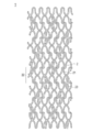
- FIG. 2 (A) It is a mimetic diagram of a stent concerning one embodiment of the present invention. It is an electron microscope image of the molten metal powder (FIG. 2 (A)), sintered body (FIG. 2 (B)), and zinc-based alloy (FIG. 2 (C)) in Example 4.
- X to Y indicating a range means “X or more and Y or less”, and unless otherwise specified, measurement of operation and physical properties is room temperature (20 to 25 ° C.) / Relative humidity 40 to 50% RH. Measure under the following conditions.
- the 1st side surface of this invention is related with the medical implant which consists of a zinc-type alloy obtained by the extrusion process of the sintered compact containing zinc and magnesium.
- the second aspect of the present invention comprises a zinc-based alloy containing zinc and magnesium, and the zinc-based alloy has a tensile strength of 200 MPa or more and an elongation rate of more than 5% in a tensile test.
- the medical implant which can control a corrosion rate and was excellent in mechanical characteristics (especially ductility) is provided.
- the “zinc-based alloy” refers to an alloy having the highest zinc content among the alloy components as measured using an analytical instrument such as ICP-MS and ICP-AES described in the examples.
- the “zinc-based alloy” means that the zinc content in the alloy exceeds 50% by weight by measurement using an analytical instrument such as ICP-MS and ICP-AES described in Examples.
- the zinc-based alloy used for the medical implant according to the present invention is also referred to as “zinc-based alloy according to the present invention”.
- a medical implant such as a stent requires a radial force that keeps the lumen of the blood vessel for a certain period after vascular dilation, but an intima is formed on the stent surface. Once done, radial force is no longer needed. Therefore, it is desirable to gradually disassemble a stent that has finished its role in the medium to long term.
- this decomposition is performed by corrosion of a zinc-based alloy.
- the corrosion rate does not increase excessively as much as an alloy containing magnesium as a main component.
- the zinc-based alloy which is the material for the medical implant according to the present invention, contains magnesium in addition to zinc, and therefore has a higher corrosion rate than a medical implant made of zinc alone. Therefore, the medical implant according to the present invention can control the corrosion rate by adjusting the contents of zinc and magnesium. That is, the medical implant according to the present invention can control the corrosion rate without a polymer coat layer for adjusting the corrosion rate.
- the medical implant according to the present invention can improve the mechanical strength (tensile strength) by using a zinc-based alloy containing magnesium as compared to the case of zinc alone. This is considered to be because dislocation is suppressed by solid solution of magnesium atoms in the zinc crystal lattice. Due to the high mechanical strength (tensile strength) of the medical implant material, the radial force can be maintained even if the medical implant is thin.
- a polycrystalline metal such as a zinc-magnesium alloy easily slips (deforms) within crystal grains and stops at the crystal grain boundaries according to the Hall-Petch equation. For this reason, when the crystal grains are fine, the slip distance within the crystal grains is limited, and the resistance to deformation increases. Therefore, it is guessed that the zinc-type alloy which concerns on this invention can obtain the outstanding tensile strength.
- the present inventors have also found a problem that a magnesium-containing zinc-based alloy obtained by a conventional casting method has poor mechanical properties, particularly ductility. If the ductility of the medical implant material is low, for example, when the medical implant is expanded with a balloon and is left in the body, the medical implant may be broken due to expansion (and overexpansion) by the balloon.
- a zinc-based alloy obtained by extruding a sintered body of zinc and magnesium is a magnesium-containing zinc-based material obtained by extruding a cast material composed of zinc and magnesium. It has also been found that mechanical properties, particularly ductility, are superior to those of alloys.
- a magnesium-containing zinc-based alloy is produced by a casting method, a highly brittle intermetallic compound phase such as Mg 2 Zn 11 or MgZn 2 is formed at the crystal grain boundary of the alloy.
- a zinc-based alloy is produced by extruding a sintered body of zinc and magnesium as in the present invention, since the fine powder is used as a raw material, the crystal grain size of the zinc-based alloy is reduced. As a result, the intermetallic compound existing at the crystal grain boundary is dispersed, and is less likely to be a starting point of fracture. For this reason, it is presumed that the zinc-based alloy according to the present invention has excellent ductility.
- Examples of medical implants according to the present invention include stents and stent grafts.
- the medical implant according to the present invention is a stent.
- the stent is a balloon-expandable stent (balloon expandable stent), similar to a conventionally used stent.
- the shape of the stent is not particularly limited, and a conventionally known shape can be adopted. For example, what formed the fiber by knitting a fiber, what provided the opening part in the pipe (tubular body), etc. are mentioned.
- FIG. 1 the shape of a stent is illustrated in FIG.
- the stent 1 is made of a zinc-based alloy 2 and has a substantially rhomboid element 21 having a notch therein as a basic unit.
- a plurality of substantially rhombic elements 21 are continuously arranged in the minor axis direction and joined to form an annular unit 22.
- the annular unit 22 is connected to an adjacent annular unit via a linear connecting member 23.
- the plurality of annular units 22 are continuously arranged in the axial direction in a partially coupled state.
- the stent 1 has a cylindrical body that is open at both ends and extends between the ends in the longitudinal direction.
- the stent 1 has a substantially diamond-shaped notch, and has a structure that can be expanded and contracted in the radial direction of the cylindrical body by deforming the notch.
- the shape of the stent is not limited to the illustrated embodiment, and is a cylindrical body having both end portions open and extending in the longitudinal direction between the both end portions.
- the structure includes a large number of notches communicating with the side surface and the inner surface, and a structure that can expand and contract in the radial direction of the cylindrical body by deforming the notches.
- the cross-sectional shape of the zinc-based alloy constituting the stent is not particularly limited, and examples thereof include a rectangle, a circle, an ellipse, and a polygon other than a rectangle.
- the conventional thickness of the medical implant can be used.
- the thickness of the zinc-based alloy is, for example, about 5 to 1000 ⁇ m, and is preferably about 20 to 500 ⁇ m, more preferably about 50 to 200 ⁇ m, from the relationship between supportability and placement time. Since the zinc-based alloy according to the present invention has excellent tensile strength, the implant can be made thin.
- the size of the medical implant is also adjusted appropriately according to its purpose and function.
- the outer diameter of the stent before expansion is preferably about 0.3 to 5 mm, more preferably about 0.4 to 4.5 mm, and particularly preferably about 0.5 to 1.6 mm.
- the length of the medical implant is not particularly limited, and can be appropriately selected depending on the disease to be treated.
- the length is preferably about 5 to 100 mm, more preferably about 6 to 50 mm.
- the length of the stent is preferably about 1.5 to 4 mm, and more preferably about 2 to 3 mm.
- the medical implant which concerns on this invention consists of a zinc-type alloy obtained by the extrusion process of the sintered compact containing zinc and magnesium.
- the medical implant according to the present invention is made of a zinc-based alloy containing zinc and magnesium that has a tensile strength of 200 MPa or more and an elongation of more than 5% in a tensile test.
- the zinc-based alloy according to the present invention essentially contains magnesium, and in one embodiment, the zinc content exceeds 50% by weight.
- the elemental composition is a value measured by measurement using ICP-MS or ICP-AES described in Examples.
- the zinc-based alloy which is a material for the medical implant according to the present invention, contains magnesium in addition to zinc, the corrosion rate is higher than that of a medical implant made of zinc alone. Furthermore, mechanical strength (tensile strength) can be improved by using a zinc-based alloy containing magnesium as compared with the case of zinc alone.
- the present invention consists of more than 50 wt.% And less than 100 wt.% Zinc, more than 0 wt.% And less than 50 wt.% Magnesium, and the balance unavoidable impurities.
- the zinc-based alloy according to the present invention comprises 97% by weight or more and less than 100% by weight of zinc, more than 0% by weight of 3% by weight or less of magnesium, and the balance of inevitable impurities.
- the zinc-based alloy according to the present invention is composed of 99% by weight or more and less than 100% by weight zinc, more than 0% by weight and 1% by weight magnesium or less, and the balance of inevitable impurities.
- the zinc-based alloy according to the present invention comprises 99.3% by weight to 99.95% by weight of zinc, 0.05% by weight to 0.7% by weight of magnesium, and the balance of inevitable impurities. .
- “inevitable impurities” means zinc alloy that exists in the raw material or is inevitably mixed in the manufacturing process.
- the inevitable impurities are originally unnecessary impurities, but are a very small amount and do not affect the characteristics of the zinc-based alloy, and thus are allowable impurities.
- silicon (Si) is 0.01% by weight or less
- aluminum (Al) is 0.01% by weight or less
- titanium (Ti) is 0.0% by weight as unavoidable impurities.
- iron (Fe) 0.005 wt% or less iron (Fe) 0.005 wt% or less, nickel (Ni) 0.005 wt% or less, copper (Cu) 0.005 wt% or less, manganese (Mn) 0.005 wt% % Or less, lead (Pb) 0.01% by weight or less, and cadmium (Cd) 0.01% by weight or less.
- the zinc-based alloy is represented by the following formula (1).
- A is an unavoidable impurity
- the zinc-based alloy represented by the formula (1) contains 97 wt% or more of zinc and magnesium of more than 0 and 3 wt% or less with respect to the whole alloy.
- the magnesium content is 3% by weight or less, there is an advantage that high ductility can be obtained.
- the zinc alloy according to the present invention has high ductility. Therefore, by using the zinc-based alloy according to the present invention for medical implants, the medical implant can be prevented from being expanded (and over-expanded) and from being bent, twisted, or pulsated before and after placement. it can. In addition, since the zinc-based alloy has high ductility, there is an advantage that the degree of freedom of the stent structure is increased.
- the zinc-based alloy according to the present invention is also excellent in tensile strength. Therefore, by using the zinc-based alloy according to the present invention for a medical implant, the medical implant can be made thin while maintaining a high radial force.
- the medical implant according to the present invention is made of a zinc-based alloy having a tensile strength of 200 MPa or more and an elongation rate exceeding 5% in a tensile test under the following conditions. That is, in one embodiment of the present invention, a medical implant is provided in which the tensile strength of the zinc-based alloy is 200 MPa or more and the elongation percentage exceeds 5%.
- the tensile test for calculating and measuring the tensile strength and the elongation rate is performed under the following conditions.
- the tensile strength is calculated by dividing the maximum tensile force required to break the test piece by the sectional area of the test piece when the following test piece is pulled until it breaks under the following conditions. .
- the maximum elongation rate at the time of breaking the test piece is measured.
- Test piece Round bar Diameter of test piece: 3 mm Test piece length: 40 mm Test piece parallel part length: 15mm Strain rate: 5 ⁇ 10 ⁇ 4 s ⁇ 1 .
- the tensile strength of the zinc-based alloy is more preferably 230 MPa or more, and further preferably 250 MPa or more.
- the elongation percentage of the zinc-based alloy is more preferably 10% or more, and further preferably 15% or more.
- the upper limit of the tensile strength and elongation rate is not particularly limited, but substantially the tensile strength is 330 MPa or less and the elongation rate is 30% or less.
- the tensile strength of the zinc-based alloy in the tensile test is 200 MPa or more and 330 MPa or less, and in another preferred embodiment, it is 230 MPa or more and 330 MPa or less, and in a further more preferred embodiment, 250 MPa or more.
- the elongation percentage of the zinc-based alloy in the tensile test is more than 5% and not more than 30%, and in another preferred embodiment, it is not less than 10% and not more than 30%, and in still another more preferred embodiment, It is 15% or more and 30% or less.
- the composition of the zinc-based alloy is represented by the above formula (1), and the sintered body is extruded. May be manufactured.
- the above tensile test is measured at room temperature (25 ° C.).
- the corrosion rate of the zinc-based alloy according to the present invention is faster than when zinc is used alone, and is slower than when magnesium is used alone. Since the corrosion rate of zinc-based alloys varies depending on the medical implant used, it cannot be generally stated.
- a zinc-based alloy according to an embodiment of the present invention is obtained by extrusion of a sintered body containing zinc and magnesium. That is, the third aspect of the present invention includes a step of sintering a metal powder containing zinc and magnesium to obtain a sintered body; and a step of extruding the sintered body to obtain a zinc-based alloy.
- the present invention relates to a method for manufacturing an implant.
- metal powder containing zinc and magnesium is used as a raw material.
- the contents of zinc and magnesium in the alloy can be arbitrarily set.
- Zinc used as a raw material is preferably high-purity, and the lower the content of inevitable impurities contained, the better.
- the purity of the raw material zinc is, for example, 99.99% by weight or more (the upper limit is 100% by weight).
- Magnesium used as a raw material is also preferably highly pure, and the lower the content of inevitable impurities contained, the better.
- the purity of the raw material magnesium is, for example, 99.9% by weight or more (the upper limit is 100% by weight).
- the powder particle diameter of zinc used as a raw material is preferably small from the viewpoint of suppressing the formation of intermetallic compounds, for example, 200 ⁇ m or less, and preferably 150 ⁇ m or less.
- the lower limit of the particle size of the powder is not particularly limited, but is, for example, 1 ⁇ m or more.
- the metal powder particle size is a value measured by a sieving method.
- the powder particle size of magnesium used as a raw material is also preferably small from the viewpoint of suppressing the formation of intermetallic compounds, for example, 200 ⁇ m or less, preferably 150 ⁇ m or less.
- the minimum of a particle size is not restrict
- a mixture obtained by mixing zinc powder and magnesium powder in a powder state may be sintered.
- raw material zinc and raw material magnesium are mixed and sintered so as to be uniform.
- a mixing method it can carry out by conventionally well-known methods, such as a powder mill, for example.
- a metal powder having a uniform particle size can be obtained by preparing a metal powder from zinc and magnesium by melting.
- a molten metal powder containing zinc and magnesium is sintered.
- Zinc and magnesium used for the preparation of the melted metal powder may be the above powder or an ingot.
- the method for obtaining the molten metal powder is not particularly limited as long as it is a method capable of obtaining a powder having a small particle diameter, and a conventionally known method such as a centrifugal spray method, a water spray method, a gas spray method, etc. can be employed. It is preferable to carry out by a centrifugal spray method. In the centrifugal spraying method, the molten metal is rapidly cooled, so that the formation of highly brittle intermetallic compounds can be suppressed. Further, the centrifugal spray method has an advantage that particles having a sharp particle size distribution can be obtained.
- the melting temperature of the raw material in producing the molten metal powder is not particularly limited as long as it is equal to or higher than the melting point of the raw material. Moreover, it is preferable that a melting temperature is 500 degrees C or less from a viewpoint of preventing evaporation of zinc.
- the particle diameter of the molten metal powder is preferably small from the viewpoint of suppressing the formation of intermetallic compounds, for example, 300 ⁇ m or less, preferably 200 ⁇ m or less, and more preferably 150 ⁇ m or less.
- the minimum of a particle size is not restrict
- the particle size can be arbitrarily controlled by adjusting the rotational speed of the disk in the case of the centrifugal spraying method, and adjusting the gas pressure in the case of the gas spraying method.
- the method for producing a medical implant according to the present invention includes a step of sintering a metal powder containing zinc and magnesium to obtain a sintered body.
- the metal powder may be a mixture of zinc powder and magnesium powder or the above-mentioned melted metal powder.
- the sintering method includes spark plasma sintering (SPS), hot press sintering, hot isostatic pressing (HIP), millimeter wave sintering, and microwave sintering.
- SPS spark plasma sintering
- HIP hot isostatic pressing
- millimeter wave sintering millimeter wave sintering
- microwave sintering microwave sintering.
- the sintering is preferably spark plasma sintering. That is, it is preferable that a sintered body containing zinc and magnesium is obtained by spark plasma sintering.
- Sintering is preferably performed in a vacuum atmosphere or an inert gas atmosphere such as argon gas or nitrogen gas.
- the sintering temperature is not particularly limited, but is, for example, 100 to 400 ° C., preferably 300 to 350 ° C. Further, the rate of temperature rise is, for example, 1 to 20 ° C./min, preferably 5 to 15 ° C./min.
- Sintering is preferably performed under pressure, and the conditions at that time are 10 to 100 MPa, preferably 30 to 50 MPa.
- the holding time for sintering is, for example, 10 to 60 minutes, preferably 30 to 40 minutes.
- the voltage applied to the metal powder is, for example, 1000 to 3500 V, and the current is, for example, 2.5 to 15 A, although not particularly limited. It is.
- the average crystal grain size of the sintered body after sintering and before extrusion is, for example, 100 ⁇ m or less, preferably 50 ⁇ m or less, more preferably 30 ⁇ m or less.
- the minimum of a particle size is not restrict
- the medical implant according to the present invention is characterized by comprising a zinc-based alloy obtained by the extrusion process of the sintered body.
- the manufacturing method of the medical implant which concerns on this invention is characterized by including the process of extruding the said sintered compact and obtaining a zinc-type alloy.
- a rod is obtained by extruding the sintered body, and a medical implant is manufactured using the rod as a material.
- the rod shape is not particularly limited and may be appropriately adjusted according to the purpose.
- the diameter is 0.05 to 20 cm
- the rod length is, for example, 0.01 to 5 m.
- a pipe may be obtained by extruding the sintered body, and a medical implant may be manufactured using the pipe as a material.
- a stent may be created using the pipe as a material.
- a medical implant such as a hollow stent can be more easily manufactured by creating a pipe by extrusion of a sintered body.
- in the method for producing a medical implant in the step of obtaining a zinc-based alloy, a sintered body is extruded to create a hollow zinc-based alloy pipe.
- Extrusion may be any of hot extrusion, cold extrusion, or warm extrusion, but from the viewpoint of workability, hot extrusion is preferably employed.
- the extrusion ratio in the extrusion process is, for example, 5 to 50, and the extrusion ram speed is 1 to 10 mm / second.
- the conditions for hot extrusion are not particularly limited.
- the preheating temperature is 100 to 400 ° C.
- the preheating time is 1 to 30 minutes.
- the crystal grain size of the zinc-based alloy crystal obtained by the extrusion process becomes smaller than before the extrusion.
- the average crystal grain size of the zinc-based alloy crystal is preferably 50 ⁇ m or less, more preferably 30 ⁇ m or less, still more preferably 10 ⁇ m or less, and particularly preferably 5 ⁇ m or less.
- the zinc-based alloy is a small crystal having an average crystal grain size of 5 ⁇ m or less, generation of intermetallic compounds is reduced, and ductility can be improved.
- a medical implant made of a zinc-based alloy containing zinc and magnesium, wherein the zinc-based alloy has an average crystal grain size of 5 ⁇ m or less.
- the average crystal grain size of the zinc-based alloy crystal is most preferably 3 ⁇ m or less. Although the minimum of a particle size is not restrict
- limited in particular, For example, it is 0.01 micrometer or more (for example, 0.1 micrometer or more). In one embodiment, the average crystal grain size of the zinc-based alloy crystal is 0.01 to 5 ⁇ m. In another embodiment, the average crystal grain size of the zinc-based alloy crystal is 0.1 to 5 ⁇ m. In yet another embodiment, the average crystal grain size of the zinc-based alloy crystal is 0.1-3 ⁇ m. For example, if the extrusion ratio in the extrusion process (extrusion ratio cross-sectional area of the sintered body / cross-sectional area of the extruded product) is increased, the average crystal grain size can be reduced.
- the average crystal grain size of the above zinc-based alloy or sintered body can be obtained by image analysis based on microscopic observation. More specifically, (1) an arbitrary surface of a zinc-based alloy or sintered body is polished by using diamond abrasive grains to make a mirror surface, and then this surface is etched with hydrochloric acid, and (2) scanning Using a scanning electron microscope (SEM), an arbitrary location is selected from the etched surfaces, and an image is obtained by photographing at a predetermined magnification. (3) This image is, for example, image analysis software “Image-Pro Plus” ( By analyzing using Media Cybernetics, the average value of the maximum ferret diameters of all the crystals observed in three or more fields of view can be obtained.
- image analysis software “Image-Pro Plus” By analyzing using Media Cybernetics, the average value of the maximum ferret diameters of all the crystals observed in three or more fields of view can be obtained.
- the average crystal grain size of the zinc-based alloy or sintered body is as follows. (1) Polishing an arbitrary surface of the zinc-based alloy or sintered body using diamond abrasive grains or the like. Then, this surface is etched with hydrochloric acid. (2) Using a scanning electron microscope (SEM), an arbitrary location is selected from the etched surfaces. (3) A predetermined magnification is applied to the location. (4) The obtained crystal analysis image is analyzed using, for example, image analysis software “Image-Pro Plus” (manufactured by Media Cybernetics). The average value of the maximum ferret diameters of all the crystals observed in the above visual field can be obtained.
- SEM scanning electron microscope
- the method using EBSD is suitable for a crystal having a smaller particle size (observation at a high magnification), as long as an image capable of analyzing the crystal structure is obtained, any one of the above two measurement methods is used. It may be adopted. You may confirm that the crystal grain size of the image obtained by the scanning electron microscope (SEM) and the crystal grain size of the image obtained by electron beam backscattering analysis (EBSD) correspond. However, when measuring the average crystal grain size of the zinc-based alloy, the cross section perpendicular to the extrusion direction in the extrusion process is measured.
- SEM scanning electron microscope
- EBSD electron beam backscattering analysis
- the rod thus produced is arbitrarily processed to produce a desired medical implant.
- a desired medical implant for example, in the case of a stent, the center portion of the rod is drawn out by machining to form a pipe shape. This can be cut into a stent pattern by laser processing, and further subjected to chemical polishing and electrolytic polishing to produce a stent.
- Example 1 Zinc ingot (purity 99.99%) and magnesium ingot (purity 99.9%), which are raw materials of the alloy, were melted in an electric furnace at a ratio of 99.9: 0.1 (weight ratio). Using the obtained molten metal, a melted metal powder having a powder particle size of 5 ⁇ m or more and 150 ⁇ m or less was obtained by centrifugal spraying.
- a sintered body was obtained by discharge plasma sintering (device name: discharge plasma sintering apparatus, manufacturer: manufactured by SPS Syntex).
- the sintering conditions are as follows: Atmosphere: Vacuum Sintering temperature: 300 ° C Temperature increase rate: 15 ° C./min Pressure: 30 MPa Holding time: 30 minutes Voltage: 1100V Current: 2.5A.
- the sintered body is extruded by hot extrusion (equipment name: 2000 kN hydraulically driven molding machine, manufacturer: Shibayama Machine), and is rod-shaped (diameter: 0.7 cm, length: 0.5 m). Alloy 1 was obtained. Extrusion conditions are shown below: Preheating temperature: 200 ° C Preheating time: 3 minutes Extrusion ratio: 32 Extrusion ram speed: 3 mm / sec.
- the average crystal grain size of the obtained zinc-based alloy 1 was 3 ⁇ m.
- Example 2 An alloy was prepared by the same method as in Example 1 except that the ratio of the zinc ingot and the magnesium ingot as raw materials of the alloy was changed to a ratio of 99.75: 0.25 (weight ratio). Obtained.
- Example 3 An alloy was prepared by the same method as in Example 1 except that the ratio of the zinc ingot and the magnesium ingot as raw materials of the alloy was changed to a ratio of 99.5: 0.5 (weight ratio). Obtained.
- Example 4 An alloy was prepared in the same manner as in Example 1 except that the ratio of the zinc ingot and the magnesium ingot, which were the raw materials of the alloy, was changed to a ratio of 99: 1 (weight ratio), and a zinc-based alloy 4 was obtained.
- the average crystal grain size of the zinc-based alloy 4 was 3 ⁇ m.
- the average crystal grain size of the sintered body before extrusion in Example 4 was 15 ⁇ m.
- FIG. 2 shows the molten metal powder in Example 4 (FIG. 2A, magnification: 100 times), sintered body (FIG. 2B, magnification: 200 times), and zinc-based alloy 1 (FIG. 2 ( C), magnification: 1000 times) electron microscope image (SEM model name: JSM-6500F, manufactured by JEOL).
- the fact that the zinc-based alloy was obtained by extruding the sintered body means that the presence of irregular boundaries (old powder grain boundaries) between metal powder particles as shown in FIG. It can be confirmed by observing the degree).
- the average crystal grain size was determined by crystal analysis by electron beam backscattering analysis (EBSD, OIM detector: DVC5 type detector, TSL Solutions Inc., software: OIM Data Collection 5.31 and OIM Data Analysis 5.31). .
- Comparative Example 1 A zinc ingot and a magnesium ingot were mixed at the same weight ratio as in Example 1, and a comparative metal 1 having a rod shape (diameter: 0.7 cm, length: 0.5 m) was formed by a casting method (melting temperature: 500 ° C.). Obtained.
- the obtained comparative metal 1 had an average crystal grain size of 20 ⁇ m.
- Comparative Example 2 A zinc ingot and a magnesium ingot were mixed at the same weight ratio as in Example 2, and a comparative metal 2 having a rod shape (diameter: 0.7 cm, length: 0.5 m) was formed by a casting method (melting temperature: 500 ° C.). Obtained.
- Comparative Example 3 A zinc ingot and a magnesium ingot were mixed at the same weight ratio as in Example 3, and a comparative metal 3 having a rod shape (diameter: 0.7 cm, length: 0.5 m) was formed by a casting method (melting temperature: 500 ° C.). Obtained.
- Comparative Example 4 A zinc ingot and a magnesium ingot were mixed at the same weight ratio as in Example 4, and a comparative metal 4 having a rod shape (diameter: 0.7 cm, length: 0.5 m) was formed by a casting method (melting temperature: 500 ° C.). Obtained. The average grain size of the obtained comparative metal 4 was 5.5 ⁇ m.
- Comparative Example 5 A comparative metal 5 was obtained by producing a rod by the same method as in Example 1 except that a zinc ingot was used alone as a raw material.
- Comparative Example 6 A comparative metal 6 was obtained by producing a rod by the same method as in Comparative Example 1 except that a magnesium ingot was used alone as a raw material.
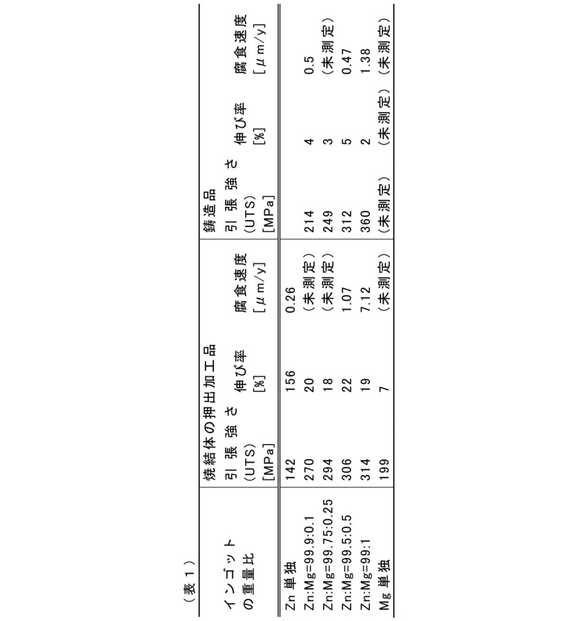
- Table 1 shows the results of the tensile test.
- the corrosion rate was calculated from the anode-cathode polarization curve obtained by applying a potential between the sample electrode and the counter electrode.
- Electrolyte solution PBS (pH 7.4)
- Reference electrode Ag / AgCl Temperature: 37 ° C Scan speed 20mV / min Sampling interval 500 ms.
Landscapes
- Engineering & Computer Science (AREA)
- Health & Medical Sciences (AREA)
- Chemical & Material Sciences (AREA)
- Mechanical Engineering (AREA)
- Materials Engineering (AREA)
- Metallurgy (AREA)
- Organic Chemistry (AREA)
- Animal Behavior & Ethology (AREA)
- Veterinary Medicine (AREA)
- Vascular Medicine (AREA)
- Biomedical Technology (AREA)
- Life Sciences & Earth Sciences (AREA)
- Heart & Thoracic Surgery (AREA)
- General Health & Medical Sciences (AREA)
- Public Health (AREA)
- Manufacturing & Machinery (AREA)
- Surgery (AREA)
- Physics & Mathematics (AREA)
- Optics & Photonics (AREA)
- Epidemiology (AREA)
- Cardiology (AREA)
- Oral & Maxillofacial Surgery (AREA)
- Transplantation (AREA)
- Materials For Medical Uses (AREA)
- Extrusion Of Metal (AREA)
- Powder Metallurgy (AREA)
- Media Introduction/Drainage Providing Device (AREA)
Abstract
亜鉛およびマグネシウムを含む焼結体の押出加工により得られる亜鉛系合金からなる、医療用インプラントにより、腐食速度をコントロールでき、かつ機械的特性(特に延性)に優れた医療用インプラントが提供される。
Description
本発明は、亜鉛系合金からなる医療用インプラント、およびその製造方法に関する。
従来、狭心症や心筋梗塞などの虚血性心疾患は冠動脈の狭窄部に対する経皮経管的冠動脈形成術(PTCA)等により、大腿動脈や頚動脈の虚血性疾患などは狭窄部に対する経皮経管的血管形成術(PTA)等により、治療が行われている。これらの治療法はいずれも、先端部に小さく折りたたまれたバルーンを装着したカテーテルを用いて、狭窄または閉塞してしまった血管を拡張することにより、血液の流れを確保、再開させる手技である。これらの治療法では、身体を切り開いて治療するよりも傷口が小さくて済むため、侵襲性が低いという利点がある。
カテーテルを使用した治療では、拡張した血管が再狭窄または閉塞するのを防止するため、金属製のステントを留置して血管の開存を確保する場合がある。ステントは、1本の金属パイプから切り出されたものや、金属線からなるメッシュ状、コイル状等のものがあるが、いずれも縮径可能な管状構造を有する。ステントは、縮径状態でカテーテルにより血管内に挿入され、狭窄部において血管内腔を機械的に支持するよう拡径され留置されるものである。
ステントは、血管拡張後、一定期間は血管の内腔を開存させておくだけのラジアルフォース(半径方向の強度)が必要である。しかし、所定期間経過後、ステントがない状態で、血管の拡張状態を維持するできる状態になると、ステントによるラジアルフォースは必要なくなる。したがって、中長期的に役目を終えたステント等の医療用インプラントは徐々に分解していく方が望ましい。
例えば、ステントに代表される上記のような生分解性医療用インプラント製造の材料として、マグネシウムのような腐食しやすい金属等が用いられている。例えば、米国特許出願公開第2013/0261735号明細書には、マグネシウムまたはマグネシウム合金から鋳造によって形成される足場(scaffold)を含むステントが記載されている。
米国特許出願公開第2013/0261735号明細書に記載のようなマグネシウム合金は腐食速度が非常に速いため、マグネシウム合金の表面に生分解性ポリマーを塗布してコート層等を形成することにより、腐食速度が調節されている。しかしながら、生分解性ポリマーからなるコート層は、挿入時または留置時にステント本体から剥離したり、インプラント拡張時に金属の伸長に追従できず破断したりすることがあった。この場合、コート層による分解速度の調節ができなくなる可能性があり、使用上の問題となる。
マグネシウム以外の腐食性金属として、亜鉛が知られている。米国特許出願公開第2013/0261735号明細書には、ステントの足場(scaffold)として、腐食速度の速いマグネシウム合金からなるコアを腐食速度の遅い亜鉛からなるシェルにて被覆した支柱(strut)を用いるものが開示されている。しかしながら、亜鉛単独では腐食速度が過度に遅いという問題があった。
さらに、腐食速度を高めるため、亜鉛とマグネシウムとの合金を用いることも考えられるが、一般的手法である鋳造法により形成されたマグネシウム含有亜鉛系合金は、機械的特性(特に、延性)が十分でないという課題があることを、本発明者らは見出した。
したがって、本発明は、上記事情を鑑みてなされたものであり、腐食速度をコントロールでき、かつ機械的特性(特に延性)に優れた医療用インプラントを提供することを目的とする。
本発明者らは、上記の問題を解決すべく、鋭意研究を行った結果、亜鉛およびマグネシウムを含む焼結体を押出加工することにより得られてなる亜鉛系合金を医療用インプラントに用いることにより、上記課題が解決されることを見出し、本発明の完成に至った。
以下、本発明の実施の形態を説明する。なお、本発明は、以下の実施の形態のみには限定されない。
本明細書において、範囲を示す「X~Y」は「X以上Y以下」を意味し、特記しない限り、操作および物性等の測定は室温(20~25℃)/相対湿度40~50%RHの条件で測定する。
[医療用インプラント]
本発明の第一の側面は、亜鉛およびマグネシウムを含む焼結体の押出加工により得られる亜鉛系合金からなる、医療用インプラントに関する。本発明の第二の側面は、亜鉛およびマグネシウムを含む亜鉛系合金からなり、前記亜鉛系合金は、引張試験において、引張り強さが200MPa以上で、かつ伸び率が5%を超える、医療用インプラントに関する。本発明によれば、腐食速度をコントロールでき、かつ機械的特性(特に延性)に優れた医療用インプラントが提供される。なお、本明細書において「亜鉛系合金」とは、実施例に記載のICP-MSおよびICP-AES等の分析機器を用いた測定により、合金成分中で亜鉛含量が最も多いものをいう。好ましくは、本明細書において「亜鉛系合金」とは、実施例に記載のICP-MSおよびICP-AES等の分析機器を用いた測定により、合金中の亜鉛含量が50重量%を超えるものをいう。また、本発明に係る医療用インプラントに用いられる亜鉛系合金を、「本発明に係る亜鉛系合金」とも称する。
本発明の第一の側面は、亜鉛およびマグネシウムを含む焼結体の押出加工により得られる亜鉛系合金からなる、医療用インプラントに関する。本発明の第二の側面は、亜鉛およびマグネシウムを含む亜鉛系合金からなり、前記亜鉛系合金は、引張試験において、引張り強さが200MPa以上で、かつ伸び率が5%を超える、医療用インプラントに関する。本発明によれば、腐食速度をコントロールでき、かつ機械的特性(特に延性)に優れた医療用インプラントが提供される。なお、本明細書において「亜鉛系合金」とは、実施例に記載のICP-MSおよびICP-AES等の分析機器を用いた測定により、合金成分中で亜鉛含量が最も多いものをいう。好ましくは、本明細書において「亜鉛系合金」とは、実施例に記載のICP-MSおよびICP-AES等の分析機器を用いた測定により、合金中の亜鉛含量が50重量%を超えるものをいう。また、本発明に係る医療用インプラントに用いられる亜鉛系合金を、「本発明に係る亜鉛系合金」とも称する。
上記したように、ステントのような医療用インプラントには、血管拡張後、一定期間は血管の内腔を開存させておくだけのラジアルフォースが必要であるが、ステント表面に血管内膜が形成された後は、ラジアルフォースは必要なくなる。したがって、中長期的に役目を終えたステントは、徐々に分解していく方が望ましい。本発明においては、この分解を、亜鉛系合金の腐食によって行う。
本発明において推測されるメカニズムを、以下に説明する。
本発明に係る医療用インプラントには、亜鉛を主成分として含む亜鉛系合金が用いられる。このため、マグネシウムを主成分とする合金ほどには、過度に腐食速度が速くならない。一方、本発明に係る医療用インプラントの材料である亜鉛系合金は、亜鉛に加えてマグネシウムを含むため、亜鉛単独からなる医療用インプラントと比べて腐食速度が速くなる。このため、本発明に係る医療用インプラントは、亜鉛及びマグネシウムの含量を調節することにより、腐食速度をコントロールできる。すなわち、本発明に係る医療用インプラントは、腐食速度調節のためのポリマーコート層がなくても、腐食速度をコントロールすることが可能である。
さらに、本発明に係る医療用インプラントは、亜鉛単独の場合と比べて、マグネシウムを含有する亜鉛系合金とすることにより、機械的強度(引張り強さ)を向上させることができる。これは、亜鉛結晶格子へのマグネシウム原子の固溶化により、転位が抑制されることによると考えられる。医療用インプラント材料の機械的強度(引張り強さ)が高いことにより、医療用インプラントを肉薄にしても、ラジアルフォースを維持することができる。また、亜鉛-マグネシウム合金のような多結晶金属は、ホール・ペッチの式により、結晶粒の粒子内ではすべり(変形)が容易に起こり、結晶粒界でそのすべりが止まると考えられている。そのため、結晶粒が微細な場合、結晶粒の粒子内でのすべりの距離が制限され、変形に対する抵抗が上がる。したがって、本発明に係る亜鉛系合金は、優れた引張り強度が得られると推察される。
本発明者らはまた、従来の鋳造法により得られたマグネシウム含有亜鉛系合金は、機械的特性、特に延性が乏しいものになるという課題を見出した。医療用インプラント材料の延性が低いと、例えば、医療用インプラントをバルーンで拡張して体内に留置する際に、バルーンによる拡張(および過拡張)等により医療用インプラントが破断してしまう虞がある。
本発明者らは、驚くべきことに、亜鉛およびマグネシウムの焼結体を押出加工して得られた亜鉛系合金は、亜鉛およびマグネシウムからなる鋳造材を押出加工して得られたマグネシウム含有亜鉛系合金と比べて、機械的特性、特に延性が優れたものになることをも見出した。鋳造法によりマグネシウム含有亜鉛系合金を作製する場合、合金の結晶粒界にMg2Zn11やMgZn2といった脆性の高い金属間化合物相が形成される。一方、本発明のように亜鉛およびマグネシウムの焼結体を押出成形して亜鉛系合金を作製する場合、微細粉末を原料として用いているため、亜鉛系合金の結晶粒径が小さくなる。その結果、結晶粒界に存在する金属間化合物が分散し、破断の起点になりにくくなる。そのため、本発明に係る亜鉛系合金は、優れた延性を有するのではないかと推測される。
なお、以上のメカニズムは推測であり、本発明の技術的範囲をなんら制限するものではない。
本発明に係る医療用インプラントとしては、ステント、ステントグラフトが例示できる。
好ましくは、本発明に係る医療用インプラントは、ステントである。例えば、ステントは、従来使用されるステントと同様に、バルーンエクスパンダブルステント(balloon-expandable stent)(バルーン拡張型ステント)である。ステントの形状も特に制限されず、従来公知の形状が採用され得る。例えば、繊維を編み上げて円筒状に形成したものや、パイプ(管状体)に開口部を設けたもの等が挙げられる。
本発明の一態様として、ステントの形状を図1に例示する。
図1に示す態様において、ステント1は、亜鉛系合金2からなり、内部に切欠き部を有する略菱形の要素21を基本単位とする。複数の略菱形の要素21がその短軸方向に連続して配置され結合することで、環状ユニット22をなしている。環状ユニット22は、隣接する環状ユニットと線状の連結部材23を介して接続されている。これにより複数の環状ユニット22が一部結合した状態で、その軸方向に連続して配置される。ステント1は、このような構成により、両末端部が開口し、該両末端部の間を長手方向に延在する円筒体をなしている。ステント1は、略菱形の切欠き部を有しており、この切欠き部が変形することによって、円筒体の径方向に拡縮可能な構造になっている。
ただし、本発明において、ステントの形状は図示した態様に限定されず、両末端部が開口し、該両末端部の間を長手方向に延在する円筒体であって、その側面上に、外側面と内側面とを連通する多数の切欠き部を有し、この切欠き部が変形することによって、円筒体の径方向に拡縮可能な構造をも含む。ステントを構成する亜鉛系合金の断面形状についても特に限定されず、例えば矩形、円形、楕円形、矩形以外の多角形等が挙げられる。
医療用インプラントの厚さは、従来の一般的なものが採用できる。例えば、ステントを例にとると、亜鉛系合金の厚さは、例えば5~1000μm程度であり、支持性と留置時間との関係から、20~500μm程度が好ましく、50~200μm程度がより好ましい。本発明に係る亜鉛系合金は、優れた引張り強さを有するため、インプラントを肉薄にできる。
医療用インプラントの大きさも、その目的や機能に合わせて適宜調節される。ステントを例にとると、拡張前におけるステントの外径は、0.3~5mm程度が好ましく、0.4~4.5mm程度がより好ましく、0.5~1.6mm程度が特に好ましい。
また、医療用インプラントの長さも特に制限されず、処置すべき疾患によって適宜選択できる。例えば、ステントを例にとると、その長さは、5~100mm程度が好ましく、6~50mm程度がより好ましい。または、ステントの長さは、1.5~4mm程度が好ましく、2~3mm程度がより好ましい場合もある。
<亜鉛系合金>
本発明に係る医療用インプラントは、亜鉛およびマグネシウムを含む焼結体の押出加工により得られる亜鉛系合金からなる。別の側面では、本発明に係る医療用インプラントは、引張試験において、引張り強さが200MPa以上で、かつ伸び率が5%を超える、亜鉛およびマグネシウムを含む亜鉛系合金からなる。本発明に係る亜鉛系合金は、マグネシウムを必須で含み、一実施形態では亜鉛の含有量が50重量%を超える。なお、本明細書において、元素組成は、実施例に記載のICP-MSまたはICP-AESを用いた測定により測定された値である。
本発明に係る医療用インプラントは、亜鉛およびマグネシウムを含む焼結体の押出加工により得られる亜鉛系合金からなる。別の側面では、本発明に係る医療用インプラントは、引張試験において、引張り強さが200MPa以上で、かつ伸び率が5%を超える、亜鉛およびマグネシウムを含む亜鉛系合金からなる。本発明に係る亜鉛系合金は、マグネシウムを必須で含み、一実施形態では亜鉛の含有量が50重量%を超える。なお、本明細書において、元素組成は、実施例に記載のICP-MSまたはICP-AESを用いた測定により測定された値である。
本発明に係る医療用インプラントの材料である亜鉛系合金は、亜鉛に加えてマグネシウムを含むため、亜鉛単独からなる医療用インプラントと比べて腐食速度が速くなる。さらに、亜鉛単独の場合と比べて、マグネシウムを含む亜鉛系合金とすることにより、機械的強度(引張り強さ)を向上させることができる。
本発明の一実施形態は、50重量%を超えて100重量%未満の亜鉛、0重量%を超えて50重量%未満のマグネシウム、および残部の不可避不純物からなる。好ましくは、本発明に係る亜鉛系合金は、97重量%以上100重量%未満の亜鉛、0重量%を超えて3重量%以下のマグネシウム、および残部の不可避不純物からなる。より好ましくは、本発明に係る亜鉛系合金は、99重量%以上100重量%未満の亜鉛、0重量%を超えて1重量%以下のマグネシウム、および残部の不可避不純物からなる。更に好ましくは、本発明に係る亜鉛系合金は、99.3重量%以上99.95重量%以下の亜鉛、0.05重量%以上0.7重量%以下のマグネシウム、および残部の不可避不純物からなる。
なお、本明細書において、「不可避不純物」とは、亜鉛系合金において、原料中に存在したり、製造工程において不可避的に混入したりするものを意味する。当該不可避不純物は、本来は不要なものであるが、微量であり、亜鉛系合金の特性に影響を及ぼさないため、許容されている不純物である。亜鉛系合金は、不可避不純物として、亜鉛系合金全体に対して、例えば、ケイ素(Si)を0.01重量%以下、アルミニウム(Al)を0.01重量%以下、チタン(Ti)を0.005重量%以下、鉄(Fe)を0.005重量%以下、ニッケル(Ni)を0.005重量%以下、銅(Cu)を0.005重量%以下、マンガン(Mn)を0.005重量%以下、鉛(Pb)を0.01重量%以下、カドミウム(Cd)を0.01重量%以下含有しても良い。
本発明の好ましい一実施形態では、亜鉛系合金が、下記式(1)で表わされる。

前記式(1)において、Aは不可避不純物であり、x、y、およびaは重量%を表し、この際、97≦x<100、0<y≦3、および0≦a<yであり、x+y+a=100である。
式(1)で表わされる亜鉛系合金は、合金全体に対して97重量%以上の亜鉛と、0を超えて3重量%以下のマグネシウムとを含む。マグネシウム含量が3重量%以下であることにより、高い延性が得られるという利点がある。
腐食速度を調節し、ステントに必要な機械的特性(延性や引張り強さ)を持たせるという観点から、式(1)において、99≦x<100、0<y≦1、および0≦a<yであり、x+y+a=100であることが好ましく、式(1)において、99.3≦x≦99.95、0.05≦y≦0.7、および0≦a<yであり、x+y+a=100であることがより好ましい。式(1)において、aの範囲は、例えば0≦a≦0.01であり、好ましくは0≦a<0.005である。
本発明にかかる亜鉛系合金は、高い延性を有する。従って、本発明にかかる亜鉛系合金を医療用インプラントに用いることにより、バルーンによる拡張(および過拡張)や、留置前後での屈曲、ねじれ、もしくは拍動などの応力による医療用インプラントの破断を防止できる。また、亜鉛系合金が高い延性を有することにより、ステント構造の自由度が高くなるという利点もある。本発明にかかる亜鉛系合金はまた、引張り強さにも優れる。従って、本発明にかかる亜鉛系合金を医療用インプラントに用いることにより、高いラジアルフォースを維持しつつ、医療用インプラントを肉薄にできる。
好ましくは、本発明に係る医療用インプラントは、下記条件の引張試験において、引張り強さが200MPa以上で、かつ伸び率が5%を超える亜鉛系合金からなる。すなわち、本発明の一実施形態では、亜鉛系合金の引張り強さが200MPa以上で、かつ伸び率が5%を超える医療用インプラントが提供される。本明細書において、引張り強さ及び伸び率を算出・測定するための引張試験は下記条件で行われる。ここで、引張り強さは、下記の試験片を下記の条件で破断するまで引張った際、その試験片を破断させるのに要した最大の引張り力を試験片の断面積で割ることにより算出する。また、伸び率は、下記の試験片を下記の条件で破断するまで引張った際、その試験片の破断時の最大の伸び率を測定する。
(引張試験の条件)
試験片の形状:丸棒
試験片の直径:3mm
試験片の長さ:40mm
試験片平行部長さ:15mm
ひずみ速度:5×10⁻⁴s-1。
試験片の形状:丸棒
試験片の直径:3mm
試験片の長さ:40mm
試験片平行部長さ:15mm
ひずみ速度:5×10⁻⁴s-1。
亜鉛系合金の引張り強さは230MPa以上であることがより好ましく、250MPa以上であることが更に好ましい。このとき、亜鉛系合金の伸び率は10%以上であることがより好ましく、伸び率が15%以上であることが更に好ましい。引張り強さや伸び率の上限は特に制限されないが、実質的には、引張り強さは330MPa以下であり、伸び率は30%以下である。本発明の一実施形態では、引張試験における亜鉛系合金の引張り強さは、200MPa以上330MPa以下であり、好ましい別の実施形態では230MPa以上330MPa以下であり、より好ましいさらに別の実施形態では250MPa以上310MPa以下である。一実施形態では、引張試験における亜鉛系合金の伸び率は、5%を超えて30%以下であり、好ましい別の実施形態では10%以上30%以下であり、より好ましいさらに別の実施形態では15%以上30%以下である。亜鉛系合金の引張り強さおよび伸び率を上記のような所望の範囲とするためには、例えば、亜鉛系合金の組成を上記式(1)で表されるものとし、焼結体の押出加工により製造すればよい。
上記の引張試験は、室温(25℃)にて測定される。
本発明に係る亜鉛系合金の腐食速度は、亜鉛を単独で用いた場合に比べて速く、マグネシウムを単独で用いた場合に比べて遅い。亜鉛系合金の腐食速度は、用いる医療用インプラントによっても異なるため、一概には言えない。
<製造方法>
本発明の一実施形態に係る亜鉛系合金は、亜鉛およびマグネシウムを含む焼結体の押出加工により得られたものである。すなわち、本発明の第三の側面は、亜鉛およびマグネシウムを含む金属粉末を焼結し、焼結体を得る工程;ならびに焼結体を押出加工し、亜鉛系合金を得る工程を含む、医療用インプラントの製造方法に関する。
本発明の一実施形態に係る亜鉛系合金は、亜鉛およびマグネシウムを含む焼結体の押出加工により得られたものである。すなわち、本発明の第三の側面は、亜鉛およびマグネシウムを含む金属粉末を焼結し、焼結体を得る工程;ならびに焼結体を押出加工し、亜鉛系合金を得る工程を含む、医療用インプラントの製造方法に関する。
以下、本発明に係る亜鉛系合金および医療用インプラントの製造方法について、より詳細に説明する。
1.亜鉛およびマグネシウムを含む金属粉末の提供
本発明に係る亜鉛系合金の製造においては、亜鉛およびマグネシウムを含む金属粉末を原料として用いる。原料粉末中の亜鉛およびマグネシウムの重量比率を調節することにより、合金中の亜鉛およびマグネシウムの含量を任意に設定することができる。
本発明に係る亜鉛系合金の製造においては、亜鉛およびマグネシウムを含む金属粉末を原料として用いる。原料粉末中の亜鉛およびマグネシウムの重量比率を調節することにより、合金中の亜鉛およびマグネシウムの含量を任意に設定することができる。
原料として用いる亜鉛は、高純度のものが好ましく、含まれる不可避不純物の含量は少ないほどよい。原料亜鉛の純度は、例えば、99.99重量%以上である(上限は100重量%)。
原料として用いるマグネシウムもまた、高純度のものが好ましく、含まれる不可避不純物の含量は少ないほどよい。原料マグネシウムの純度は、例えば、99.9重量%以上である(上限は100重量%)。
原料として用いる亜鉛の粉末粒径は、金属間化合物の形成を抑える観点から、小さいことが好ましく、例えば200μm以下であり、好ましくは150μm以下である。粉末粒径の下限は特に制限されないが、例えば1μm以上である。なお、本明細書において、金属の粉末粒径は、篩分け法により測定した値である。
原料として用いるマグネシウムの粉末粒径もまた、金属間化合物の形成を抑える観点から、小さいことが好ましく、例えば200μm以下であり、好ましくは150μm以下である。粒径の下限は特に制限されないが、例えば1μm以上である。
本発明に係る亜鉛系合金の製造方法においては、亜鉛粉末とマグネシウム粉末とを、粉末の状態で混合して得られた混合物を焼結しても良い。この場合、原料亜鉛と原料マグネシウムとを、均一となるように混合して焼結を行う。混合方法としては、例えば混粉機など従来公知の方法によって行うことができる。
一方、亜鉛粉末とマグネシウム粉末との粒径に差がある場合、均一な混合が困難になる虞がある。この場合は、亜鉛とマグネシウムとから、溶製にて金属粉末を調製することにより、均質で粒径のそろった金属粉末を得ることができる。本発明の好ましい一実施形態では、焼結体を得る工程において、亜鉛およびマグネシウムを含む溶製金属粉末を焼結する。
溶製金属粉末の調製に用いる亜鉛やマグネシウムは、上記のような粉末でもよく、インゴットでもよい。
これらの原料を加熱溶融させて溶製金属とし、粉末化する。溶製金属粉末を得る方法は、粒径の小さな粉末を得ることができる方法であれば特に制限されず、遠心噴霧法、水噴霧法、ガス噴霧法等の従来公知の方法が採用できるが、遠心噴霧法により行うことが好ましい。遠心噴霧方法では、溶融した金属が急冷されるため、脆性の高い金属間化合物の形成を抑えることができる。また、遠心噴霧法は、粒度分布のシャープな粒子が得られるという利点もある。
溶製金属粉末を作製する場合の原料の溶融温度は、原料の融点以上であれば特に制限されないが、例えば400℃以上である。また、亜鉛の蒸発を防止する観点から、溶融温度は500℃以下であることが好ましい。
溶製金属粉末の粒径は、金属間化合物の形成を抑える観点から、小さいことが好ましく、例えば300μm以下であり、好ましくは200μm以下であり、より好ましくは150μm以下である。粒径の下限は特に制限されないが、例えば1μm以上である。例えば、遠心噴霧法であれば円盤の回転速度を調節し、ガス噴霧法であればガス圧を調節すること等によって、粒径を任意に制御することができる。
2.焼結
本発明に係る医療用インプラントの製造法では、亜鉛およびマグネシウムを含む金属粉末を焼結し、焼結体を得る工程を含む。当該金属粉末は、上記のように、亜鉛粉末とマグネシウム粉末との混合物であっても、上述の溶製金属粉末であってもよい。
本発明に係る医療用インプラントの製造法では、亜鉛およびマグネシウムを含む金属粉末を焼結し、焼結体を得る工程を含む。当該金属粉末は、上記のように、亜鉛粉末とマグネシウム粉末との混合物であっても、上述の溶製金属粉末であってもよい。
金属粉末の焼結は、粉末冶金の分野において従来用いられている各種方法が採用できる。焼結の方法としては、具体的には、放電プラズマ焼結(SPS)、ホットプレス焼結、熱間静水圧焼結(HIP)、ミリ波焼結、およびマイクロ波焼結等が例示できる。製造が簡便であるという観点から、好ましくは、焼結は放電プラズマ焼結である。すなわち、亜鉛およびマグネシウムを含む焼結体が、放電プラズマ焼結により得られてなることが好ましい。
焼結は、真空雰囲気、またはアルゴンガスや窒素ガス等の不活性ガス雰囲気で行うことが好ましい。
焼結温度は特に限定するものではないが、例えば、100~400℃であり、好ましくは300~350℃である。また、昇温速度は例えば、1~20℃/分であり、好ましくは5~15℃/分である。
焼結は加圧下で行うことが好ましく、その際の条件としては、10~100MPa、好ましくは30~50MPaである。
焼結の保持時間は、例えば10~60分、好ましくは、30~40分である。
好ましい一態様である放電プラズマ焼結(SPS)により焼結する場合、特に制限されるものではないが、金属粉末に印加する電圧は、例えば1000~3500Vであり、電流は例えば2.5~15Aである。
焼結後、押出加工前の焼結体の平均結晶粒径は、例えば100μm以下であり、好ましくは50μm以下であり、より好ましくは30μm以下である。粒径の下限は特に制限されないが、例えば0.01μm以上(例えば、0.1μm以上)である。
3.押出加工
本発明に係る医療用インプラントは、上記の焼結体の押出加工により得られた亜鉛系合金からなることを特徴とする。また、本発明に係る医療用インプラントの製造方法は、上記焼結体を押出加工し、亜鉛系合金を得る工程を含むことを特徴とする。焼結体の押出加工によってロッドを得、当該ロッドを材料として医療用インプラントを製造する。ロッド形状は特に制限されず、目的に応じて適宜調整すればよいが、例えば直径0.05~20cmであり、ロッド長が例えば0.01~5mである。
本発明に係る医療用インプラントは、上記の焼結体の押出加工により得られた亜鉛系合金からなることを特徴とする。また、本発明に係る医療用インプラントの製造方法は、上記焼結体を押出加工し、亜鉛系合金を得る工程を含むことを特徴とする。焼結体の押出加工によってロッドを得、当該ロッドを材料として医療用インプラントを製造する。ロッド形状は特に制限されず、目的に応じて適宜調整すればよいが、例えば直径0.05~20cmであり、ロッド長が例えば0.01~5mである。
なお、焼結体の押出加工によってパイプを得、当該パイプを材料として医療用インプラントを製造してもよい。具体的には、焼結体を押出加工し、中空を有する亜鉛系合金のパイプを作成した後、パイプを材料としてステントを作成してもよい。この場合、焼結体の押出加工によりパイプを作成することで、中空を有するステント等の医療用インプラントをより容易に製造することができる。本発明の一実施形態では、医療用インプラントの製造方法は、亜鉛系合金を得る工程において、焼結体を押出加工し、中空を有する亜鉛系合金のパイプを作成する。
押出加工は、熱間押出、冷間押出、または温間押出のいずれであっても良いが、加工性の観点から、好ましくは熱間押出が採用される。押出加工における押出比は、例えば5~50であり、押出ラム速度は1~10mm/秒である。
熱間押出の条件は特に制限されないが、例えば、予備加熱温度が100~400℃であり、予備加熱時間が1~30分である。
押出加工によって得られた亜鉛系合金結晶の結晶粒径は、押出前と比べて更に小さくなる。亜鉛系合金結晶の平均結晶粒径は、好ましくは50μm以下であり、より好ましくは30μm以下であり、更に好ましくは10μm以下であり、特に好ましくは5μm以下である。亜鉛系合金の平均結晶粒径が5μm以下の小さな結晶であることにより、金属間化合物の発生が低減され、延性の向上を図ることができる。本発明の一実施形態では、亜鉛およびマグネシウムを含む亜鉛系合金からなり、亜鉛系合金の平均結晶粒径が5μm以下である、医療用インプラントが提供される。亜鉛系合金結晶の平均結晶粒径は、最も好ましくは3μm以下である。粒径の下限は特に制限されないが、例えば0.01μm以上(例えば、0.1μm以上)である。一実施形態では、亜鉛系合金結晶の平均結晶粒径は、0.01~5μmである。他の実施形態では、亜鉛系合金結晶の平均結晶粒径は、0.1~5μmである。さらに別の実施形態では、亜鉛系合金結晶の平均結晶粒径は、0.1~3μmである。例えば、押出加工における押出比(押出比=焼結体断面積/押出加工品断面積)を大きくすれば、平均結晶粒径を小さくすることができる。
なお、上記の亜鉛系合金や焼結体の平均結晶粒径は、顕微鏡観察に基づく画像解析によって求めることができる。より具体的には、(1)亜鉛系合金や焼結体の任意の面をダイヤモンド砥粒等を用いて研磨加工して鏡面とした後、この面を塩酸によりエッチング処理し、(2)走査型電子顕微鏡(SEM)を用いて、エッチング処理した面のうちで任意の場所を選び、所定倍率で撮影して画像を得、(3)この画像を例えば画像解析ソフト「Image-Pro Plus」(Media Cybernetics社製)を用いて解析することにより、3以上の視野内に観察される全結晶の最大フェレ径の平均値として求めることができる。また、代替的な方法としては、上記の亜鉛系合金や焼結体の平均結晶粒径は、(1)亜鉛系合金や焼結体の任意の面をダイヤモンド砥粒等を用いて研磨加工して鏡面とした後、この面を塩酸によりエッチング処理し、(2)走査型電子顕微鏡(SEM)を用いて、エッチング処理した面のうちで任意の場所を選び、(3)その場所に所定倍率で電子線後方散乱解析(EBSD)による結晶解析を行い、(4)得られた結晶解析画像を例えば画像解析ソフト「Image-Pro Plus」(Media Cybernetics社製)を用いて解析することにより、3以上の視野内に観察される全結晶の最大フェレ径の平均値として求めることができる。なお、より粒径が小さな結晶(高倍率な観察)にはEBSDを用いた手法が適しているが、結晶構造を解析可能な画像が得られる限り、上記2つの測定方法のうちいずれの方法を採用してもよい。走査型電子顕微鏡(SEM)により得られた画像の結晶粒径と電子線後方散乱解析(EBSD)により得られた画像の結晶粒径とが一致することを確認してもよい。ただし、亜鉛系合金の平均結晶粒径を測定する場合、押出加工における押出し方向に対して垂直な断面について測定する。
このようにして作製したロッドを、任意に加工し、所望の医療用インプラントを製造する。例えば、ステントであれば、機械加工によりロッドの中心部を繰り抜き、パイプ形状にする。これをレーザー加工によりステントのパターンにカットし、さらに化学研磨、電解研磨を施しステントを作製することができる。
本発明の効果を、以下の実施例および比較例を用いて説明する。ただし、本発明の技術的範囲が以下の実施例のみに制限されるわけではない。
(実施例1)
合金の原料である亜鉛インゴット(純度99.99%)とマグネシウムインゴット(純度99.9%)とを、99.9:0.1(重量比)の割合で電気炉で溶解した。得られた溶融金属を用いて、遠心噴霧法により、粉末粒径5μm以上150μm以下の溶製金属粉末を得た。
合金の原料である亜鉛インゴット(純度99.99%)とマグネシウムインゴット(純度99.9%)とを、99.9:0.1(重量比)の割合で電気炉で溶解した。得られた溶融金属を用いて、遠心噴霧法により、粉末粒径5μm以上150μm以下の溶製金属粉末を得た。
次いで、得られた溶製金属粉末を用いて、放電プラズマ焼結(機器名:放電プラズマ焼結装置、メーカー:SPSシンテックス製)により焼結体を得た。焼結の条件を以下に示す:
雰囲気: 真空
焼結温度: 300℃
昇温速度: 15℃/分
圧力: 30MPa
保持時間: 30分
電圧: 1100V
電流: 2.5A。
雰囲気: 真空
焼結温度: 300℃
昇温速度: 15℃/分
圧力: 30MPa
保持時間: 30分
電圧: 1100V
電流: 2.5A。
次いで、上記焼結体を熱間押出により押出加工(機器名:2000kN油圧駆動式成形機、メーカー:柴山機械)し、ロッド形状(直径:0.7cm、長さ:0.5m)の亜鉛系合金1を得た。押出加工の条件を以下に示す:
予備加熱温度: 200℃
予備加熱時間: 3分
押出比: 32
押出ラム速度: 3mm/秒。
予備加熱温度: 200℃
予備加熱時間: 3分
押出比: 32
押出ラム速度: 3mm/秒。
得られた亜鉛系合金1の平均結晶粒径は、3μmであった。
(実施例2)
合金の原料である亜鉛インゴットとマグネシウムインゴットとの割合を99.75:0.25(重量比)の割合に変更した以外は実施例1と同様の方法により合金を調製し、亜鉛系合金2を得た。
合金の原料である亜鉛インゴットとマグネシウムインゴットとの割合を99.75:0.25(重量比)の割合に変更した以外は実施例1と同様の方法により合金を調製し、亜鉛系合金2を得た。
(実施例3)
合金の原料である亜鉛インゴットとマグネシウムインゴットとの割合を99.5:0.5(重量比)の割合に変更した以外は実施例1と同様の方法により合金を調製し、亜鉛系合金3を得た。
合金の原料である亜鉛インゴットとマグネシウムインゴットとの割合を99.5:0.5(重量比)の割合に変更した以外は実施例1と同様の方法により合金を調製し、亜鉛系合金3を得た。
(実施例4)
合金の原料である亜鉛インゴットとマグネシウムインゴットとの割合を99:1(重量比)の割合に変更した以外は実施例1と同様の方法により合金を調製し、亜鉛系合金4を得た。亜鉛系合金4の平均結晶粒径は、3μmであった。なお、実施例4における押出加工前の焼結体の平均結晶粒径は、15μmであった。図2は、実施例4における溶製金属粉末(図2(A)、倍率:100倍)、焼結体(図2(B)、倍率:200倍)、および亜鉛系合金1(図2(C)、倍率:1000倍)の電子顕微鏡像(SEM機種名:JSM-6500F、JEOL社製)である。亜鉛系合金が焼結体の押出加工で得られたことは、図2(B)に示すような、金属粉末粒子同士の不規則な境界(旧粉末粒界)の存在をSEM(倍率200倍程度)で観察することより確認できる。また、平均結晶粒径は、電子線後方散乱解析(EBSD、OIM検出器:DVC5型検出器、株式会社TSLソリューションズ、ソフトウェア:OIM Data Collection5.31およびOIM Data Analysis5.31)による結晶解析により求めた。
合金の原料である亜鉛インゴットとマグネシウムインゴットとの割合を99:1(重量比)の割合に変更した以外は実施例1と同様の方法により合金を調製し、亜鉛系合金4を得た。亜鉛系合金4の平均結晶粒径は、3μmであった。なお、実施例4における押出加工前の焼結体の平均結晶粒径は、15μmであった。図2は、実施例4における溶製金属粉末(図2(A)、倍率:100倍)、焼結体(図2(B)、倍率:200倍)、および亜鉛系合金1(図2(C)、倍率:1000倍)の電子顕微鏡像(SEM機種名:JSM-6500F、JEOL社製)である。亜鉛系合金が焼結体の押出加工で得られたことは、図2(B)に示すような、金属粉末粒子同士の不規則な境界(旧粉末粒界)の存在をSEM(倍率200倍程度)で観察することより確認できる。また、平均結晶粒径は、電子線後方散乱解析(EBSD、OIM検出器:DVC5型検出器、株式会社TSLソリューションズ、ソフトウェア:OIM Data Collection5.31およびOIM Data Analysis5.31)による結晶解析により求めた。
(比較例1)
実施例1と同様の重量比で亜鉛インゴットとマグネシウムインゴットとを混合し、鋳造法(溶融温度:500℃)によりロッド形状(直径:0.7cm、長さ:0.5m)の比較金属1を得た。得られた比較金属1の平均結晶粒径は20μmであった。
実施例1と同様の重量比で亜鉛インゴットとマグネシウムインゴットとを混合し、鋳造法(溶融温度:500℃)によりロッド形状(直径:0.7cm、長さ:0.5m)の比較金属1を得た。得られた比較金属1の平均結晶粒径は20μmであった。
(比較例2)
実施例2と同様の重量比で亜鉛インゴットとマグネシウムインゴットとを混合し、鋳造法(溶融温度:500℃)によりロッド形状(直径:0.7cm、長さ:0.5m)の比較金属2を得た。
実施例2と同様の重量比で亜鉛インゴットとマグネシウムインゴットとを混合し、鋳造法(溶融温度:500℃)によりロッド形状(直径:0.7cm、長さ:0.5m)の比較金属2を得た。
(比較例3)
実施例3と同様の重量比で亜鉛インゴットとマグネシウムインゴットとを混合し、鋳造法(溶融温度:500℃)によりロッド形状(直径:0.7cm、長さ:0.5m)の比較金属3を得た。
実施例3と同様の重量比で亜鉛インゴットとマグネシウムインゴットとを混合し、鋳造法(溶融温度:500℃)によりロッド形状(直径:0.7cm、長さ:0.5m)の比較金属3を得た。
(比較例4)
実施例4と同様の重量比で亜鉛インゴットとマグネシウムインゴットとを混合し、鋳造法(溶融温度:500℃)によりロッド形状(直径:0.7cm、長さ:0.5m)の比較金属4を得た。得られた比較金属4の平均結晶粒径は5.5μmであった。
実施例4と同様の重量比で亜鉛インゴットとマグネシウムインゴットとを混合し、鋳造法(溶融温度:500℃)によりロッド形状(直径:0.7cm、長さ:0.5m)の比較金属4を得た。得られた比較金属4の平均結晶粒径は5.5μmであった。
(比較例5)
原料として亜鉛インゴットを単独で用いた以外は実施例1と同様の方法によりロッドを作製し、比較金属5を得た。
原料として亜鉛インゴットを単独で用いた以外は実施例1と同様の方法によりロッドを作製し、比較金属5を得た。
(比較例6)
原料としてマグネシウムインゴットを単独で用いた以外は比較例1と同様の方法によりロッドを作製し、比較金属6を得た。
原料としてマグネシウムインゴットを単独で用いた以外は比較例1と同様の方法によりロッドを作製し、比較金属6を得た。
(引張試験)
上記の亜鉛系合金および比較金属を用いて、室温(25℃)にて下記条件にて引張試験(機器名:AUTOGRAPH AG-X 50kN、島津製作所社製)を行い、引張り強さおよび伸び率を測定した(n=3):
試験片の形状:丸棒
試験片の直径:3mm
試験片の長さ:40mm
試験片平行部長さ:15mm
ひずみ速度:5×10⁻⁴s-1。
上記の亜鉛系合金および比較金属を用いて、室温(25℃)にて下記条件にて引張試験(機器名:AUTOGRAPH AG-X 50kN、島津製作所社製)を行い、引張り強さおよび伸び率を測定した(n=3):
試験片の形状:丸棒
試験片の直径:3mm
試験片の長さ:40mm
試験片平行部長さ:15mm
ひずみ速度:5×10⁻⁴s-1。
引張試験の結果を表1に示す。
(腐食速度)
上記の亜鉛系合金および比較金属を用いて、TAFEL外挿法により腐食速度を測定した。結果を表1に示す。
上記の亜鉛系合金および比較金属を用いて、TAFEL外挿法により腐食速度を測定した。結果を表1に示す。
(TAFEL外挿法(電気化学的試験))
サンプル極と対極の間に電位を印加することで得られたアノード・カソード分極曲線より腐食速度を算出した。
サンプル極と対極の間に電位を印加することで得られたアノード・カソード分極曲線より腐食速度を算出した。
使用機器:HZ7000(北斗電工株式会社)
電解質溶液:PBS(pH7.4)
参照電極:Ag/AgCl
温度:37℃
スキャン速度20mV/min
サンプリング間隔500ms。
電解質溶液:PBS(pH7.4)
参照電極:Ag/AgCl
温度:37℃
スキャン速度20mV/min
サンプリング間隔500ms。
本出願は、2015年3月26日に出願された日本特許出願番号2015-064577号に基づいており、その開示内容は、参照され、全体として、組み入れられている。
1 ステント、
2 亜鉛系合金、
21 略菱形の要素、
22 環状ユニット、
23 連結部材。
2 亜鉛系合金、
21 略菱形の要素、
22 環状ユニット、
23 連結部材。
Claims (12)
- 亜鉛およびマグネシウムを含む亜鉛系合金からなり、前記亜鉛系合金は、引張試験において、引張り強さが200MPa以上で、かつ伸び率が5%を超える、医療用インプラント。
- 亜鉛およびマグネシウムを含む焼結体の押出加工により得られる亜鉛系合金からなる、医療用インプラント。
- 前記亜鉛系合金は、引張試験において、引張り強さが200MPa以上で、かつ伸び率が5%を超える、請求項2に記載の医療用インプラント。
- 前記焼結体が、放電プラズマ焼結により得られてなる、請求項2または3に記載の医療用インプラント。
- 前記亜鉛系合金が、下記式(1):

で表わされる、請求項1~4のいずれか1項に記載の医療用インプラント。 - 前記式(1)において、99.3≦x≦99.95、0.05≦y≦0.7、および0≦a<yであり、x+y+a=100である、請求項5に記載の医療用インプラント。
- ステントである、請求項1~6のいずれか1項に記載の医療用インプラント。
- 前記亜鉛系合金の平均結晶粒径が、5μm以下である、請求項1~7のいずれか1項に記載の医療用インプラント。
- 亜鉛およびマグネシウムを含む金属粉末を焼結し、焼結体を得る工程;ならびに
前記焼結体を押出加工し、亜鉛系合金を得る工程を含む、医療用インプラントの製造方法。 - 前記焼結体を得る工程において、亜鉛およびマグネシウムを含む溶製金属粉末を焼結する、請求項9に記載の医療用インプラントの製造方法。
- 前記焼結が、放電プラズマ焼結である、請求項9または10に記載の医療用インプラントの製造方法。
- 前記亜鉛系合金を得る工程において、前記焼結体を押出加工し、中空を有する亜鉛系合金のパイプを作成する、前記請求項9~11のいずれか1項に記載の医療用インプラントの製造方法。
Applications Claiming Priority (2)
| Application Number | Priority Date | Filing Date | Title |
|---|---|---|---|
| JP2015064577A JP2018082726A (ja) | 2015-03-26 | 2015-03-26 | 亜鉛系合金からなる医療用インプラント、およびその製造方法 |
| JP2015-064577 | 2015-03-26 |
Publications (1)
| Publication Number | Publication Date |
|---|---|
| WO2016152908A1 true WO2016152908A1 (ja) | 2016-09-29 |
Family
ID=56977531
Family Applications (1)
| Application Number | Title | Priority Date | Filing Date |
|---|---|---|---|
| PCT/JP2016/059165 Ceased WO2016152908A1 (ja) | 2015-03-26 | 2016-03-23 | 亜鉛系合金からなる医療用インプラント、およびその製造方法 |
Country Status (2)
| Country | Link |
|---|---|
| JP (1) | JP2018082726A (ja) |
| WO (1) | WO2016152908A1 (ja) |
Cited By (2)
| Publication number | Priority date | Publication date | Assignee | Title |
|---|---|---|---|---|
| EP3650053A4 (en) * | 2017-07-06 | 2021-04-14 | Biotyx Medical (Shenzhen) Co., Ltd. | IMPLANTABLE DEVICE |
| JP2021155838A (ja) * | 2020-03-25 | 2021-10-07 | 国立大学法人弘前大学 | 高強度Zn焼結体の製造方法及び高強度Zn焼結体 |
Citations (4)
| Publication number | Priority date | Publication date | Assignee | Title |
|---|---|---|---|---|
| JP2008081842A (ja) * | 2006-09-01 | 2008-04-10 | National Institute Of Advanced Industrial & Technology | 高強度高延性難燃性マグネシウム合金及びその製造方法 |
| CN104212998A (zh) * | 2014-08-21 | 2014-12-17 | 北京大学 | 一种Zn-Mg系锌合金及其制备方法与应用 |
| CN104587532A (zh) * | 2014-03-19 | 2015-05-06 | 西安爱德万思医疗科技有限公司 | 一种人体可吸收的耐蚀高强韧锌镁合金植入材料 |
| WO2015147183A1 (ja) * | 2014-03-28 | 2015-10-01 | 古河電気工業株式会社 | 亜鉛合金管材とその製造方法、及びそれを用いてなるステントとその製造方法 |
-
2015
- 2015-03-26 JP JP2015064577A patent/JP2018082726A/ja active Pending
-
2016
- 2016-03-23 WO PCT/JP2016/059165 patent/WO2016152908A1/ja not_active Ceased
Patent Citations (4)
| Publication number | Priority date | Publication date | Assignee | Title |
|---|---|---|---|---|
| JP2008081842A (ja) * | 2006-09-01 | 2008-04-10 | National Institute Of Advanced Industrial & Technology | 高強度高延性難燃性マグネシウム合金及びその製造方法 |
| CN104587532A (zh) * | 2014-03-19 | 2015-05-06 | 西安爱德万思医疗科技有限公司 | 一种人体可吸收的耐蚀高强韧锌镁合金植入材料 |
| WO2015147183A1 (ja) * | 2014-03-28 | 2015-10-01 | 古河電気工業株式会社 | 亜鉛合金管材とその製造方法、及びそれを用いてなるステントとその製造方法 |
| CN104212998A (zh) * | 2014-08-21 | 2014-12-17 | 北京大学 | 一种Zn-Mg系锌合金及其制备方法与应用 |
Cited By (3)
| Publication number | Priority date | Publication date | Assignee | Title |
|---|---|---|---|---|
| EP3650053A4 (en) * | 2017-07-06 | 2021-04-14 | Biotyx Medical (Shenzhen) Co., Ltd. | IMPLANTABLE DEVICE |
| JP2021155838A (ja) * | 2020-03-25 | 2021-10-07 | 国立大学法人弘前大学 | 高強度Zn焼結体の製造方法及び高強度Zn焼結体 |
| JP7557689B2 (ja) | 2020-03-25 | 2024-09-30 | 国立大学法人弘前大学 | 高強度Zn焼結体の製造方法 |
Also Published As
| Publication number | Publication date |
|---|---|
| JP2018082726A (ja) | 2018-05-31 |
Similar Documents
| Publication | Publication Date | Title |
|---|---|---|
| JP7448581B2 (ja) | マグネシウム合金、その製造方法およびその使用 | |
| US7641983B2 (en) | Medical devices including composites | |
| US9402936B2 (en) | Medical devices having alloy compositions | |
| US7938854B2 (en) | Medical devices and methods of making the same | |
| JP6392250B2 (ja) | 生体内分解性の内部人工器官およびそれに使用する生体内分解性マグネシウム合金を加工する方法 | |
| JP2019019412A (ja) | マグネシウム合金、その製造方法およびその使用 | |
| US20080091267A1 (en) | Medical devices including hardened alloys | |
| AU2006221058A1 (en) | Process for forming an improved metal alloy stent | |
| WO2009012101A2 (en) | Endoprostheses containing boride intemetallic phases | |
| JP2018515156A (ja) | 体内プロテーゼ用の生体分解性マグネシウム合金の微細構造 | |
| JP2017501756A (ja) | 体内プロテーゼ用の生侵食性マグネシウム合金マイクロ構造 | |
| WO2015147183A1 (ja) | 亜鉛合金管材とその製造方法、及びそれを用いてなるステントとその製造方法 | |
| CA2620169A1 (en) | Medical devices having alloy compositions | |
| EP3884923B1 (en) | Pt-co based alloy for medical use | |
| JP2018082726A (ja) | 亜鉛系合金からなる医療用インプラント、およびその製造方法 | |
| WO2016152909A1 (ja) | 亜鉛系合金からなる医療用インプラント | |
| WO2026040739A1 (zh) | 钼合金、医用植入器件和制备方法 | |
| JP2016105749A (ja) | ガルバニック腐食ステント | |
| US20160015540A1 (en) | Stent | |
| WO2021076510A1 (en) | Methods for manufacturing radiopaque intraluminal stents comprising cobalt-based alloys with supersaturated tungsten content | |
| DE102013208958A1 (de) | Verfahren zur Herstellung eines Stents aus einer CoCr-Legierung |
Legal Events
| Date | Code | Title | Description |
|---|---|---|---|
| 121 | Ep: the epo has been informed by wipo that ep was designated in this application |
Ref document number: 16768811 Country of ref document: EP Kind code of ref document: A1 |
|
| NENP | Non-entry into the national phase |
Ref country code: DE |
|
| 122 | Ep: pct application non-entry in european phase |
Ref document number: 16768811 Country of ref document: EP Kind code of ref document: A1 |
|
| NENP | Non-entry into the national phase |
Ref country code: JP |