WO2016152755A1 - 物体認識装置 - Google Patents
物体認識装置 Download PDFInfo
- Publication number
- WO2016152755A1 WO2016152755A1 PCT/JP2016/058640 JP2016058640W WO2016152755A1 WO 2016152755 A1 WO2016152755 A1 WO 2016152755A1 JP 2016058640 W JP2016058640 W JP 2016058640W WO 2016152755 A1 WO2016152755 A1 WO 2016152755A1
- Authority
- WO
- WIPO (PCT)
- Prior art keywords
- vehicle
- unit
- processing
- recognition
- processing load
- Prior art date
Links
Images


Classifications
-
- B—PERFORMING OPERATIONS; TRANSPORTING
- B60—VEHICLES IN GENERAL
- B60R—VEHICLES, VEHICLE FITTINGS, OR VEHICLE PARTS, NOT OTHERWISE PROVIDED FOR
- B60R21/00—Arrangements or fittings on vehicles for protecting or preventing injuries to occupants or pedestrians in case of accidents or other traffic risks
-
- G—PHYSICS
- G08—SIGNALLING
- G08G—TRAFFIC CONTROL SYSTEMS
- G08G1/00—Traffic control systems for road vehicles
- G08G1/16—Anti-collision systems
Definitions
- the present invention relates to an object recognition apparatus.
- Patent Document 1 discloses a technique for selecting a different collision avoidance method depending on the reliability of a detected obstacle.
- the apparatus of Patent Document 1 calculates the reliability based on the length of time during which recognition can be performed, and determines the vehicle control content according to the reliability.
- Patent Document 1 has a problem that the reliability of the recognition result itself cannot be improved. For example, depending on the number and positions of detected objects, a sufficient time for recognition processing cannot be secured, and the reliability of the recognition result is lowered.
- the present invention provides an object recognition apparatus that can improve the reliability of the recognition result of the object itself.
- the object recognition device includes a vehicle external information acquisition unit that acquires external information of the vehicle, an object detection unit that detects an object existing outside the vehicle based on the external information of the vehicle, A recognition processing unit that performs recognition processing on the object detected by the object detection unit, a processing load calculation unit that calculates a processing load in the recognition processing unit based on a detection result in the object detection unit, and a vehicle load based on the processing load A vehicle control content determination unit that determines the control content.
- the reliability itself of the recognition result of the object can be improved. Therefore, it becomes possible to implement
- FIG. 1 It is a block diagram of the object recognition apparatus of Example 1. It is a detailed block diagram of the object recognition apparatus of Example 1. 2 is a block diagram of an image processing unit according to the first exemplary embodiment.
- FIG. FIG. 3 is a block diagram illustrating an object detection unit according to the first exemplary embodiment, where (A) illustrates processing of an initial detection unit and (B) illustrates processing of a processing region calculation unit. It is a figure explaining the processing content of the processing load calculation part of Example 1, (A) shows the processing time list
- FIG. 1 It is a block diagram of the object recognition apparatus of Example 2.
- FIG. 6 is a block diagram of an image processing unit according to a second embodiment. It is a figure explaining the processing content of the object detection part of Example 3, (A) shows the distance to each object or each process area which the object distance information acquisition part acquired, (B) is a recognition process. The process which selects the target object or processing area is shown. It is a figure explaining the processing content of the object detection part of Example 3, (A) shows the approach speed of each object which the approach speed / time acquisition part acquired, (B) becomes an object of recognition processing. The process which selects an object or a process area is shown. It is a figure explaining the processing content of the processing load calculation part of Example 3, (A) shows the processing time list
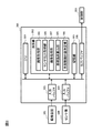
- the present embodiment is applied to an object recognition apparatus configured as shown in FIGS. 1 and 2, for example.
- This object recognition device performs appropriate control according to the vehicle state and the surrounding environment in order to improve the safety of the automobile.
- the object recognition apparatus can perform control capable of traveling safely based on, for example, the positions of objects around the vehicle and the driving state of the host vehicle.
- this object recognition device functionally detects an object existing outside the vehicle based on the image acquisition unit 102 as a vehicle external information acquisition unit that acquires information outside the vehicle.
- Object detection unit 103 a recognition processing unit 104 that performs recognition processing on the object detected by the object detection unit 103, and a processing load in the recognition processing unit 104 based on a detection result of the object detection unit 103
- vehicle control content determination unit 106 that determines the control content of the vehicle based on the processing load.
- the object detection unit 103 and the recognition processing unit 104 can also be referred to as an image processing unit 107.
- the object recognition apparatus also includes a sensor unit 108 that senses vehicle behavior information (for example, vehicle speed related information and steering information), and a sensor output acquisition unit 109 that acquires sensor output data.
- vehicle behavior information for example, vehicle speed related information and steering information
- sensor output acquisition unit 109 that acquires sensor output data.
- vehicle speed related information is information on speed and acceleration
- steering information is angular velocity of the steering angle.
- the image acquisition unit 102 acquires an image photographed by the imaging device 101 as information outside the vehicle.
- the vehicle external information acquisition unit is not limited to the image acquisition unit 102, and may acquire information outside the vehicle using a radar, a sonar, a millimeter wave, or the like.
- the processing load calculated by the processing load calculation unit 105 is represented by the time required for the recognition process.
- FIG. 2 shows a more specific block diagram of this object recognition apparatus.
- the imaging apparatus 101 includes an optical system (lens), an imaging element, and the like.
- the lens collects light in the optical axis direction
- the imaging element converts the light into a digital signal in accordance with the intensity of the light, generates an image, and outputs the image to the image acquisition unit 111.
- the imaging apparatus 101 includes one or more camera modules and outputs an image of the surrounding environment.
- the sensor unit 108 includes a vehicle speed sensor, a gyro, and the like, and measures speed and angular velocity. Specifically, the sensor unit 108 includes one or more sensor modules and outputs sensor information.
- the processing device 201 includes a CPU (central processing unit) 301, an arithmetic unit 302, an input buffer 303 having a function of temporarily storing signals of the sensor unit 108, and a function of temporarily storing signals of the imaging device 101.
- the calculation unit 302 includes an image acquisition unit 102, a sensor output acquisition unit 109, an image processing unit 107, a processing load calculation unit 105, and a vehicle control content determination unit 106.
- the image acquisition unit 102 acquires an image from the imaging device 101.
- the image data is temporarily stored in the storage unit 305 from the input buffer 303, and the image data is read at a predetermined processing timing under the control of the CPU 301.
- the sensor output acquisition unit 109 acquires the sensor information on the velocity and angular velocity from the sensor unit 102.
- the sensor output acquisition unit 109 has a simple numerical calculation function. For example, according to the control of the CPU 301, the sensor output acquisition unit 109 calculates the total travel distance of the vehicle at a predetermined time based on the acquired sensor information, and outputs the calculated distance as sensor data. be able to.
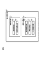
- the image processing unit 107 detects an object in the image using the image data acquired by the image acquisition unit 102 and the sensor data acquired by the sensor output acquisition unit 109. As shown in FIG. 3, the image processing unit 107 performs an object detection unit 103 that detects an object existing outside the vehicle based on information outside the vehicle, and a recognition process for the object detected by the object detection unit 103. A recognition processing unit 104.
- the object detection unit 103 detects at least one of the size, number, and type of an object existing outside the vehicle. Specifically, the object detection unit 103 includes an initial detection unit 401 that analyzes image data and calculates initial detection data, and a processing region calculation unit 402 that calculates a processing region based on the initial detection data.
- the initial detection unit 401 receives image data as input, and outputs a feature amount generally used in object detection as initial detection data.
- the initial detection unit 401 calculates, for example, luminance, edge strength, edge angle, and Hough transform, and outputs the initial detection data. Further, the initial detection unit 401 analyzes the feature amount, performs histogram processing, line detection, and circle detection, and outputs the initial detection data. This process is performed for each pixel, but the image data may be divided into predetermined units and performed for each unit. In this case, the total value, average value, variance, standard deviation, etc. of the luminance values of the pixels included in the unit are output.
- the initial detection unit 401 stores the calculated initial detection data in the storage unit 305 in association with the image data acquired by the image acquisition unit 102 and the sensor data acquired by the sensor output acquisition unit 109.
- the processing area calculation unit 402 outputs the processing area calculated based on the initial detection data.
- the conditions set as the processing area by the processing area calculation unit 402 differ depending on the detection target and the detection method. For example, the processing area calculation unit 402 divides the image data into a predetermined size when the edge strength of the pixel is within a predetermined value, and determines the position where the average value of the luminance value in one unit including the pixel is within the predetermined value. Output as processing area A. Further, the processing area calculation unit 402 outputs, as another processing area B, the position of a line having a predetermined direction and a luminance value among the lines detected by the line detection. The processing area calculation unit 402 stores these processing areas in the storage unit 305 in association with predetermined detection applications.
- the recognition processing unit 104 uses a moving body detection unit 403 that detects a moving body in an optical flow, a video conversion unit 404 that makes it easy to detect an object by converting the viewpoint of image data, and a result obtained by the conversion by the video conversion unit. And a three-dimensional object detection unit 405 that detects a three-dimensional object as an object.
- the moving body detection unit 403 detects the moving body based on the optical flow value calculated by combining the plurality of image data acquired by the image acquisition unit 102 and the sensor data acquired by the sensor output acquisition unit 109.
- a flow other than the moving body is generated by the movement of the own vehicle, the flow due to the movement of the own vehicle can be canceled using the own vehicle behavior included in the sensor data.
- a flow of only the moving body is obtained.
- the obtained flows are grouped using the geometric relationship and the time series change of the flow, and detected as a moving object.
- the moving body detection unit 403 calculates the relative moving speed of the moving body from the grouped moving body flow vector and the ground contact position of the moving body.
- the moving body detection unit 403 outputs the absolute moving speed calculated by combining the relative moving speed and the vehicle speed of the own vehicle obtained from the sensor data, and the ground contact position of the moving body as a set. Since the technique of object detection using an optical flow is known, it will not be described in further detail.
- the moving body detection unit 403 can reduce the processing time by processing only the processing region output by the processing region calculation unit 402.
- the video conversion unit 404 performs processing for converting the image acquired by the image acquisition unit 102 into coordinates with the ground as a reference plane, and outputs an overhead image that is a video as if the host vehicle was looked down from directly above. Coordinate conversion is performed using a coordinate conversion table created based on camera parameters.
- the camera parameters are focal length, pixel pitch, lens distortion, camera mounting position and posture in the vehicle. Using this camera parameter, the video conversion unit 404 can perform coordinate conversion of a video in a range from the host vehicle to a predetermined distance and output it as an overhead image. This overhead image is used when a solid object detection unit 405 described later detects a solid object.
- the three-dimensional object detection unit 405 uses a plurality of images output from the video conversion unit 404 and the sensor information output from the sensor output acquisition unit 109, and a three-dimensional object existence region that is a region where the presence or absence of a three-dimensional object can be recognized. , Output the distance to the area.
- the solid object detection unit 405 for example, translates or rotates the first image according to the sensor information, subtracts the second image from the moved first image, and outputs a difference image. By subtracting by moving the first image in parallel or rotating so that the road surface pattern of the first image and the road surface pattern of the second image overlap, the difference on the road surface becomes smaller, and the other three-dimensional image The difference is large in the object existence area.
- the three-dimensional object detection unit 405 performs a labeling process on the difference image, outputs a label image, and outputs statistical information for each label.
- the labeling process calculates the gray level difference between neighboring pixels for each pixel included in the difference image, and if the magnitude of the gray level difference is within a predetermined range, the same number is assigned as a number unique to each area. Is output as A portion where the gray value of the difference image is lower than a predetermined value is treated as a road surface or an unknown area.
- the solid object detection unit 405 outputs this label image as a solid object region.
- the three-dimensional object detection unit 405 adds and outputs statistical information (the area of each label, the geometric information of the circumscribed rectangle, and the barycentric position) to the labeling image.
- the three-dimensional object detection unit 405 performs a matching process from the history information of the three-dimensional object region. A parallax image is generated from the result of this matching, and the distance to each three-dimensional object region is calculated and output.
- the three-dimensional object detection unit 405 can reduce the processing time by processing only the processing region output by the processing region calculation unit 402.
- the processing load calculation unit 105 calculates the processing load by summing up the processing loads for each object that is the target of the recognition process when a plurality of objects that are the targets of the recognition process are detected.
- the processing load calculation unit 105 outputs the time required to process the image output and sensor data based on the data read from the storage unit as the object recognition processing time.
- the processing load is determined according to the size of the processing area set for the object in the image.
- the processing load calculation unit 105 reads the unique number of the detection application associated with the processing area stored in the storage unit, and reads the processing time list corresponding to the unique number.
- This processing time list is, for example, a list in which the size of the processing area and the processing time are described (see FIG. 5A).
- the processing load calculation unit 105 can obtain the processing time when the detection application is executed by scanning the processing time list using the processing area recorded in the storage unit 305 as a key.
- the processing load calculation unit 105 calculates processing times for all the processing areas stored in the storage unit 305 and stores the processing times in the storage unit 305.
- the processing load calculation unit 105 outputs the object recognition processing time based on all the stored processing times. Since the object recognition processing time is a time necessary for completing the execution of all necessary detection applications, for example, the object recognition processing time is represented by a sum (linear sum) of stored processing times.
- the vehicle control content determination unit 106 refers to the behavior conversion list stored in the storage unit, converts the processing time calculated by the processing load calculation unit 105 into a vehicle behavior, and outputs the vehicle behavior.
- This behavior conversion list is, for example, a list in which processing time and vehicle speed are described, and specifically outputs the vehicle speed.
- the vehicle behavior output by the vehicle control content determination unit 106 is not limited to the vehicle speed, and may be steering information, blinker operation, or the like.
- the control unit 107 executes control according to the vehicle control content output by the vehicle control content determination unit 106.
- the object recognition device calculates the processing time required to perform object detection using the image captured by the imaging device 101 and the sensor output measured by the sensor unit 103 as inputs, and the vehicle is based on the processing time. Since the behavior is input to the control unit 107, it can be executed without sacrificing the accuracy of object recognition necessary to ensure safety.
- the initial detection unit 401 uses the image acquired by the image acquisition unit 102 as an input to calculate feature quantities such as edge pairs, edge directions, and geometric information.
- the feature quantity to be calculated must be appropriately selected according to the characteristics of the object to be detected.
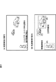
- FIG. 4 (A) is an example in which initial detection is executed by taking as an example a case where a person and a vehicle are detected using a front camera when the host vehicle is moving. Based on the result of executing the initial detection, the processing area calculation unit 402 calculates a processing area used by the moving object detection unit 403 and the three-dimensional object detection unit 405.
- FIG. 4B illustrates an example in which the processing area calculation unit 402 calculates one pedestrian detection processing area and two three-dimensional object detection processing areas from the initial detection result.
- the processing load calculation unit 105 calculates the processing time from this processing area.
- FIG. 5A shows an example in which the processing load calculation unit 105 calculates each processing time with reference to the processing time list for moving object detection and three-dimensional object detection.
- the processing load calculation unit 105 adds the calculated processing time and outputs a total value.
- the vehicle control content determination unit 106 converts the total processing time into vehicle behavior and outputs the vehicle behavior.
- FIG. 5B shows an example in which the vehicle control content determination unit 106 converts the processing time into the vehicle speed with reference to the vehicle behavior conversion list.
- the vehicle speed corresponding to the processing time of 100 ms is 12 km / h.
- the control unit 107 outputs the calculated vehicle speed.
- step 701 the imaging apparatus 101 captures the periphery of the vehicle and outputs the captured image.
- the sensor unit 102 measures the velocity and the angular velocity.
- step 703 the image acquisition unit 102 acquires an image from the sensor unit 103 and transmits it to the storage unit 305.
- step 704 the sensor output acquisition unit 104 acquires speed and angular velocity information from the sensor unit 103 and transmits the information to the storage unit 305.
- the initial detection unit 401 receives image data as input, and outputs a feature amount generally used in object detection as initial detection data.
- the processing area calculation unit 402 outputs the processing area calculated based on the initial detection data.
- step 707 the processing load calculation unit 105 outputs the time required to process the image output and the sensor data based on the data read from the storage unit 305 as the object detection processing time.
- step 708 the vehicle control content determination unit 106 converts the processing time calculated by the processing load calculation unit 105 into a vehicle behavior with reference to a behavior conversion list stored in advance in the storage unit 305, and converts the vehicle behavior into the vehicle behavior. Output.
- step 709 the control unit 107 executes control according to the vehicle behavior output from the vehicle control content determination unit 106.
- the moving body detection unit 403 detects a moving body based on the optical flow value calculated by combining the plurality of image data acquired by the image acquisition unit 102 and the sensor data acquired by the sensor output acquisition unit 109.
- the video conversion unit 404 converts the image acquired by the image acquisition unit 102 into coordinates with the ground as a reference plane, and displays an overhead image that is a video as if looking down from the vehicle directly above.
- the three-dimensional object detection unit 405 uses the plurality of images output from the video conversion unit 404 and the sensor information output from the sensor output acquisition unit 109 as a region where the presence or absence of the three-dimensional object can be recognized. Output the existence area and the distance to the area.
- this object recognition device it is possible to calculate the time required for the image recognition application to complete the object detection process and perform vehicle control according to the result. That is, according to this object recognition apparatus, since the vehicle control content is determined so as to ensure the time for performing the object recognition process, the reliability of the object recognition result itself can be improved.
- the vehicle control content determination unit 106 includes an allowable processing load calculation unit 106a.
- the object recognition device stores an allowable processing load allowed for the recognition processing, and determines the control content of the vehicle so that the processing load falls within the allowable processing load.
- the description common to the first embodiment is omitted.
- the allowable processing load is calculated based on at least one of the distance to the object and the relative speed. Note that the calculation method of the allowable processing load may be changed according to the object detection method, the vehicle behavior, the application, and the like.
- the vehicle control content determination unit 106 compares the allowable processing time with the required processing time, and outputs information that the vehicle behavior is not changed when the allowable processing time is longer than the required processing time.
- the object recognition device calculates the allowable processing time for performing object detection from the current vehicle behavior, compares the processing allowable time with the processing time, By not changing the vehicle behavior when the time is longer than the processing time, unnecessary changes in the vehicle behavior can be reduced.
- the object recognition apparatus according to the present embodiment selects a target object to be recognized by the recognition processing unit 104 under a predetermined condition. That is, the object recognition apparatus according to the present embodiment does not calculate the recognition processing load for all detected objects, but particularly an object with a high priority of processing (for example, the closest object, the object with the highest relative speed). Etc.) is calculated. Accordingly, by limiting the target objects for recognition processing to those having high necessity, it is possible to suppress excessive calculation of the processing load and to perform vehicle control that is more suitable for the situation outside the vehicle. The description common to those in the first or second embodiment is omitted.
- the object detection unit 103 detects an object having the highest relative speed as at least an object to be recognized. Further, when there are a plurality of objects, the object detection unit 103 detects an object having the closest distance as at least an object to be recognized. The detection result of the object detection unit 103 is output to the recognition processing unit 104 and the processing load calculation unit 105.
- the object detection unit 103 includes an object distance information acquisition unit 406 that acquires a distance to an object, a distance to the acquired object, and a vehicle behavior of the host vehicle. And an approach speed / time acquisition unit 407 for calculating the approach speed and approach time of the object.
- the object distance information acquisition unit 406 acquires the currently required object distance information based on the object position information stored in the storage unit 305. Specifically, the object distance information acquisition unit 406 acquires the current object distance information by estimating the current object position information from the past object position information and the current vehicle behavior information. .
- the approach speed / time acquisition unit 407 acquires the approach speed or approach time of the object stored in the storage unit 305.
- this is acquired as the approach speed.
- the absolute movement speed of the object finally obtained by the moving body detection unit 403 is stored in the storage unit 305
- the vehicle speed of the host vehicle at the latest time is added to this absolute movement speed.
- the relative speed may be obtained by adding.
- the recognition processing unit 104 of this embodiment includes an object distance calculation unit 408 and an approach speed / time calculation unit 409.
- the object distance calculation unit 408 calculates and outputs the distance to the object using the parallax image generated by the matching process performed by the three-dimensional object detection unit 405. The calculated distance is stored in the storage unit 305.
- the approach speed / time calculation unit 409 calculates the approach speed and approach time of the object by combining the distance information calculated by the object distance calculation unit 408 and the current vehicle speed of the host vehicle.
- the approach speed / time calculation unit 409 acquires not only the position information of the object but also the moving speed of the object, and calculates the approach speed and the approach time of the object.
- the calculated approach speed and approach time are stored in the storage unit 305.
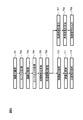
- FIG. 9A shows an example in which the object distance information acquisition unit 406 acquires the distance to each object or each processing region.
- the object detection unit 103 selects an object or processing area within a predetermined range (for example, 3 m) from the vehicle position based on the distance acquired by the object distance acquisition unit 406. select.
- FIG. 10A shows an example in which the approach speed / time acquisition unit 407 acquires the approach speed of an object located in each processing region.
- the object detection unit 103 selects the closest object based on the moving speed calculated by the approach speed / time calculation unit 409.
- FIG. 11A is an example in which the processing load calculation unit 105 calculates each processing time with reference to the processing time list for moving object detection and three-dimensional object detection.
- the processing load calculation unit 105 calculates the processing time with reference to the object selected based on the determination in FIG. 9B and the determination in FIG. In this example, the processing time of an object that satisfies both conditions is calculated.
- the vehicle control content determination unit 106 converts the processing time into vehicle behavior and outputs it.
- FIGS. 11A and 11B are examples in which the vehicle control content determination unit 106 converts the processing time into the vehicle speed with reference to the vehicle behavior conversion list.
- the control unit 107 outputs the calculated vehicle speed.
- the vehicle control content determination unit 106 compares the current vehicle speed with the vehicle speed obtained by converting the processing time, and does not change the vehicle speed if the current vehicle speed is lower. In this example, since the current vehicle speed is 20 km / h and the vehicle speed obtained by converting the processing time is 48 km / h, the vehicle speed is not changed.
- Safer control when calculating the processing allowable time, the distance to the object is acquired, and the approach speed / time between the object and the own vehicle is calculated by combining the distance and the current vehicle behavior, Safer control can be performed when the object is a moving object.
- the object recognition apparatus according to the present invention is not limited to the one described in the above embodiment, and can be appropriately changed within the scope of the present invention.
- the processing load is determined according to the size of the processing area, the processing load is not limited to this, and may be determined based on the number of objects recognized by the object recognition apparatus. Even in this case, if the number of objects is large, it can be easily determined that the processing load is large compared to the case where the number of objects is small. In this way, the processing load itself in the object detection unit 103 can be suppressed by simple determination.
Landscapes
- Engineering & Computer Science (AREA)
- Mechanical Engineering (AREA)
- Physics & Mathematics (AREA)
- General Physics & Mathematics (AREA)
- Traffic Control Systems (AREA)
Abstract
物体認識装置は、車両の外部情報を取得する車両外部情報取得部と、車両の外部情報に基づいて車両外部に存在する物体を検出する物体検出部と、物体検出部で検出された物体に対する認識処理を行う認識処理部と、物体検出部での検出結果に基づいて認識処理部における処理負荷を算出する処理負荷算出部と、処理負荷に基づいて車両の制御内容を決定する車両制御内容決定部と、を備える。
Description
本発明は、物体認識装置に関するものである。
近年、車両にカメラを搭載し、そのカメラで車両の周辺を観測し、観測された画像の中から、障害物を検知して車両制御を行う装置が研究開発されている。例えば、特許文献1では、検知した障害物の信頼度に応じて異なる衝突回避方法を選択する技術が示されている。
具体的には、この特許文献1の装置は、認識を行うことができた時間の長さに基づいて信頼度を算出し、この信頼度に応じて車両制御内容を決定している。
しかしながら、上記特許文献1の装置では、認識結果自体の信頼度を向上させることはできないという問題がある。例えば検出される物体の数や位置などによっては、認識処理の時間が十分に確保できず、認識結果の信頼度が低下してしまう。
そこで、本発明は、物体の認識結果の信頼度自体を向上させることができる物体認識装置を提供する。
本発明の第1の態様によると、物体認識装置は、車両の外部情報を取得する車両外部情報取得部と、車両の外部情報に基づいて車両外部に存在する物体を検出する物体検出部と、物体検出部で検出された物体に対する認識処理を行う認識処理部と、物体検出部での検出結果に基づいて認識処理部における処理負荷を算出する処理負荷算出部と、処理負荷に基づいて車両の制御内容を決定する車両制御内容決定部と、を備える。
本発明によれば、物体の認識結果の信頼度自体を向上させることができる。これにより、適切な車両制御を実現することが可能となる。
以下、本発明の実施の形態について、図面を参照して説明する。
本実施例は、例えば図1及び図2に示すように構成された物体認識装置に適用される。
この物体認識装置は、自動車の安全性向上のため、車両状態及び周辺環境に応じて適切な制御を行うものである。これによって、物体認識装置は、例えば車両周辺の物体の位置と自車の運転状態をもとに安全に走行可能な制御を行う事ができる。
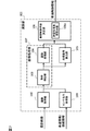
この物体認識装置は、機能的には図1に示すように、車両外部の情報を取得する車両外部情報取得部としての画像取得部102と、前記情報に基づいて車両外部に存在する物体を検出する物体検出部103と、前記物体検出部103で検出された物体に対する認識処理を行う認識処理部104と、前記物体検出部103での検出結果に基づいて前記認識処理部104における処理負荷を算出する処理負荷算出部105と、前記処理負荷に基づいて前記車両の制御内容を決定する車両制御内容決定部106と、を備える。物体検出部103と認識処理部104とは、画像処理部107とも称することができる。
また、この物体認識装置は、車両の挙動情報(例えば、車速関連情報や操舵情報)をセンシングするセンサ部108と、センサの出力データを取得するセンサ出力取得部109とを備えている。具体的には、車速関連情報とは速度や加速度の情報であり、操舵情報とは操舵角の角速度である。
画像取得部102は、車両外部の情報として、撮像装置101によって撮影された画像を取得する。但し、車両外部情報取得部は、画像取得部102に限定されるものではなく、レーダやソナー、ミリ波等を用いて車両外部の情報を取得するものであってもよい。また、処理負荷算出部105で演算される処理負荷は、認識処理に要する時間によって表わされる。
この物体認識装置をより具体的なブロック図で表わしたものが図2である。
撮像装置101は、光学系(レンズ)や撮像素子などを有する。撮像装置101は、レンズが光軸方向の光を集め、撮像素子は光の強度に合わせてデジタル信号に変換して、画像を生成し、その画像を画像取得部111に出力する。撮像装置101は、具体的には、一つ以上のカメラモジュールからなり、周辺環境の画像を出力する。
センサ部108は、車速センサやジャイロなどを有し、速度及び角速度を計測する。このセンサ部108は、具体的には1つ以上のセンサモジュールからなり、センサ情報を出力する。
処理装置201は、CPU(central processing unit、中央演算処理装置)301、演算部302、センサ部108の信号を一時的に蓄える機能を有する入力バッファ303、撮像装置101の信号を一時的に蓄える機能を有する入力バッファ304、各種信号を記憶する記憶部305、出力を一時的に蓄える出力バッファ306を備えている。
さらに、演算部302は、画像取得部102、センサ出力取得部109、画像処理部107、処理負荷算出部105、車両制御内容決定部106を備えている。
画像取得部102は、撮像装置101からの画像を取得する。この画像取得102は、画像データを一旦入力バッファ303から記憶部305へ格納し、CPU301の制御に従い、所定の処理タイミングで画像データを読み出す。
センサ出力取得部109は、センサ部102からの速度及び角速度のセンサ情報を取得する。このセンサ出力取得部109は、簡単な数値演算機能を有し、例えば、CPU301の制御に従って、取得したセンサ情報を元に所定の時刻における自車の総移動距離を計算し、センサデータとして出力することができる。
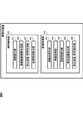
画像処理部107は、画像取得部102が取得した画像データと、センサ出力取得部109が取得したセンサデータを用いて画像中の物体を検知する。この画像処理部107は、図3に示すように、車両外部の情報に基づいて車両外部に存在する物体を検出する物体検出部103と、物体検出部103で検出された物体に対する認識処理を行う認識処理部104とを備えている。
物体検出部103は、車両外部に存在する物体の大きさ、数、種別の少なくとも一つを検出する。具体的には、物体検出部103は、画像データを解析して初期検知データを算出する初期検知部401と、初期検知データをもとに処理領域を算出する処理領域算出部402とを備える。
初期検知部401は、画像データを入力とし、物体検知で一般的に用いられている特徴量を初期検知データとして出力する。初期検知部401は、例えば、輝度、エッジ強度、エッジ角度、ハフ変換を算出し初期検知データとして出力する。さらに、初期検知部401は、この特徴量を解析し、ヒストグラム処理、線検知、円検知を実施し初期検知データとして出力する。この処理は、画素ごとに実施するが、画像データを所定の単位に区切り、その単位ごとに実施してもよい。この場合、その単位に含まれる画素の輝度値の合計値、平均値、分散、標準偏差等を出力する。初期検知部401は、以上の算出した初期検知データを、画像取得部102が取得した画像データと、センサ出力取得部109が取得したセンサデータと対応づけて、記憶部305に保存する。
処理領域算出部402は、初期検知データを元に算出した処理領域を出力する。処理領域算出部402が処理領域として設定する条件は検知する対象と検知する方法によって異なる。処理領域算出部402は、例えば、画素のエッジ強度が所定値以内であり、画像データを所定の大きさに区切り、前記画素を含む1単位における輝度値の平均値が所定値以内となる位置を処理領域Aとして出力する。また、処理領域算出部402は、線検知により検知された線のうち所定の方向と輝度値を有する線の位置を、別の処理領域Bとして出力する。処理領域算出部402はこれらの処理領域を所定の検知アプリと対応づけて記憶部305に保存する。
認識処理部104は、オプティカルフローで移動体を検知する移動体検知部403と、画像データを視点変換して物体を検知しやすくする映像変換部404と、映像変換部が変換した結果を用いて立体物を物体として検知する立体物検知部405と、を有する。
移動体検知部403は、画像取得部102が取得した複数の画像データと、センサ出力取得部109が取得したセンサデータを組み合わせて計算したオプティカルフローの値を元に移動体を検知する。自車が移動することによって移動体以外のフローも発生する場合には、センサデータに含まれる自車挙動を用いて自車移動によるフローをキャンセルすることができる。この結果、移動体のみのフローが得られる。得たフローを幾何的な関係とフローの時系列変化を用いてグループ化し、移動体として検知する。
移動体検知部403は、グループ化した移動体のフローのベクトルと、移動体の接地位置から、その移動体の相対的な移動速度を算出する。移動体検知部403は、この相対的な移動速度とセンサデータから得た自車の車速を組み合わせて算出した絶対的な移動速度と、移動体の接地位置を一組として出力する。オプティカルフローを用いた物体検知の技術は公知であるため、これ以上詳しく述べない。移動体検知部403は、処理領域算出部402が出力した処理領域内のみを処理することで、処理時間を低減することができる。
映像変換部404は、画像取得部102で取得した画像を、地面を基準面とした座標に変換する処理を行って、自車両を真上から見下ろしたような映像である俯瞰画像を出力する。座標変換はカメラパラメタを元に作成した座標変換テーブルを用いて行う。カメラパラメタは、焦点距離、画素ピッチ、レンズ歪、車両におけるカメラの取付位置及び姿勢である。このカメラパラメタを用いて、映像変換部404は、自車両から所定の距離までの範囲の映像を座標変換して俯瞰画像として出力することができる。この俯瞰画像は後述する立体物検知部405が立体物を検知する際に用いられる。
立体物検知部405は、映像変換部404が出力した複数枚の画像と、センサ出力取得部109が出力したセンサ情報を用いて、立体物の有無が認識できた領域である立体物存在領域と、その領域までの距離を出力する。
この立体物検知部405は、例えば、第一の画像をセンサ情報に従って並行移動又は回転移動して、その移動した第一の画像から第二の画像を減算して、差分画像を出力する。第一の画像の路面パタンと第二の画像の路面パタンが重なるように第一の画像を並行移動又は回転移動して減算処理を行うことで、路面では差分が小さくなり、それ以外である立体物存在領域では差分が大きくなる。立体物検知部405は、この差分画像に対してラベリング処理を行い、ラベル画像を出力し、ラベルごとに統計情報を出力する。
ラベリング処理は、この差分画像に含まれる各画素について近傍点との濃淡差を計算し、その濃淡差の大きさが所定の範囲内だった場合、同じ番号を各領域固有の番号として与えラベル画像として出力する処理である。差分画像の濃淡値が所定値より低い部分は路面又は不明領域として扱う。
立体物検知部405は、このラベル画像を立体物領域として出力する。立体物検知部405は、このラベリング画像に統計情報(各ラベルの面積、外接矩形の幾何情報、重心位置)を付加して出力する。
さらに、立体物検知部405は、この立体物領域の履歴情報からマッチング処理を行う。このマッチングの結果から視差画像を生成し、それぞれの立体物領域までの距離を計算し、出力する。立体物検知部405は、処理領域算出部402が出力した処理領域内のみを処理することで、処理時間を低減することができる。
本実施例の処理負荷算出部105は、認識処理の対象となる物体が複数検出された場合、認識処理の対象となる物体毎の処理負荷を合計して処理負荷を算出する。
具体的には、処理負荷算出部105は、記憶部から読み出したデータを元に画像出力とセンサデータを処理するのに要する時間を物体認識処理時間として出力する。ここで、処理負荷は、画像中の前記物体に対して設定される処理領域の大きさに応じて決定される。処理負荷算出部105は記憶部に記憶された処理領域に対応づけられた検知アプリの固有番号を読み出し、その固有番号と対応する処理時間リストを読み出す。この処理時間リストは、例えば、処理領域の大きさと処理時間が記述されているリストである(図5(A)参照)。
また、処理負荷算出部105は、記憶部305に記録された処理領域をキーとして処理時間リストを走査することで、検知アプリを実行した場合の処理時間を得ることができる。処理負荷算出部105は、記憶部305に記憶された全ての処理領域に対して処理時間を算出し、記憶部305へ記憶する。処理負荷算出部105は、記憶された全ての処理時間をもとに、物体認識処理時間を出力する。この物体認識処理時間は、必要な検知アプリが全て実行完了するために必要な時間であるため、例えば、記憶された処理時間の和(線形和)で表わす。
車両制御内容決定部106は、記憶部に記憶された挙動変換リストを参照して、処理負荷算出部105が算出した処理時間を車両挙動へ変換して出力する。この挙動変換リストは、例えば、処理時間と車速が記述されているリストであり、具体的には車速を出力する。この車両制御内容決定部106が出力する車両挙動は、車速に限定されず、操舵情報やウィンカー操作等であってもよい。
制御部107は、車両制御内容決定部106が出力した車両制御内容に従った制御を実行する。
このように、物体認識装置は、撮像装置101で撮像した映像とセンサ部103で計測したセンサ出力を入力として、物体検知を行うのに必要な処理時間を算出し、その処理時間を元に車両挙動を制御部107へ入力するので、安全性を確保するのに必要な物体認識の精度を犠牲にすることなく実行する事ができる。
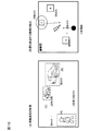
この物体認識装置の動作を、図4を用いて説明する。初期検知部401は画像取得部102が取得した画像を入力として、エッジペア、エッジ方向、幾何情報等の特徴量を算出する。算出する特徴量は検出したい物体の特性によって適切に選択する必要がある。
図4(A)は、自車両が移動している際にフロントカメラを用いて人物と車両を検出する場合を例に初期検知を実行している例である。初期検知を実行した結果を元に、処理領域算出部402は、移動体検知部403と立体物検知部405で用いる処理領域を算出する。図4(B)は、処理領域算出部402が、初期検知の結果から、歩行者検知の処理領域1つと立体物検知の処理領域2つを算出した例である。処理負荷算出部105は、この処理領域から処理時間を算出する。
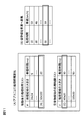
図5(A)は、処理負荷算出部105が移動体検知と立体物検知の処理時間リストを参照して、それぞれの処理時間を算出した例である。処理負荷算出部105は、算出した処理時間を加算して合計値を出力する。この例では、検知された移動体A、立体物B、立体物Cのそれぞれに要する処理時間を合計して、処理時間を20+30+50=100msと算出する。車両制御内容決定部106は、この処理時間の合計値を車両挙動に変換して出力する。
図5(B)は、車両制御内容決定部106が、車両挙動変換リストを参照して、処理時間を車速へ変換する例である。この例では、処理時間100msに対応する車速は、12km/hである。最後に、制御部107は、算出した車速を出力する。
次に、物体認識装置の動作手順を、図6を用いて説明する。
ステップ701において、撮像装置101は車両周辺を撮影してその撮影画像を出力する。ステップ702において、センサ部102は速度及び角速度を計測する。ステップ703において、画像取得部102は、センサ部103から画像を取得して記憶部305に送信する。ステップ704において、センサ出力取得部104は、センサ部103からの速度及び角速度の情報を取得して、記憶部305に送信する。ステップ705において、初期検知部401は、画像データを入力とし、物体検知で一般的に用いられている特徴量を初期検知データとして出力する。ステップ706において、処理領域算出部402は、初期検知データを元に算出した処理領域を出力する。
ステップ707において、処理負荷算出部105は、記憶部305から読み出したデータを元に画像出力とセンサデータを処理するのに要する時間を物体検知処理時間として出力する。ステップ708において、車両制御内容決定部106は、処理負荷算出部105が算出した処理時間を、記憶部305に予め記憶されている挙動変換リストを参照して、車両挙動へ変換し、車両挙動を出力する。ステップ709において、制御部107は、車両制御内容決定部106が出力した車両挙動に従った制御を実行する。
ステップ710において、移動体検知部403は、画像取得部102が取得した複数の画像データと、センサ出力取得部109が取得したセンサデータを組み合わせて計算したオプティカルフローの値を元に移動体を検知する。ステップ711において、映像変換部404は、画像取得部102で取得した画像を、地面を基準面とした座標への変換を行って、自車両を真上から見下ろしたような映像である俯瞰画像を出力する。ステップ712において、立体物検知部405は、映像変換部404が出力した複数枚の画像と、センサ出力取得部109が出力したセンサ情報を用いて、立体物の有無が認識できた領域として立体物存在領域とその領域までの距離を出力する。
この物体認識装置によれば、画像認識アプリが物体検知の処理を完了するのに必要な時間を算出して、その結果に応じた車両制御を行うことができる。即ち、この物体認識装置によれば、物体の認識処理を行う時間を確保できるように車両制御内容を決定するため、物体の認識結果の信頼度自体を向上させることができる。
次に、実施例2の物体認識装置について図7を用いて説明する。本実施例の物体認識装置は、車両制御内容決定部106が許容処理負荷算出部106aを有する。物体認識装置は、認識処理に許容される許容処理負荷を記憶し、処理負荷が許容処理負荷に収まるように車両の制御内容を決定するものである。以下の説明では、実施例1と共通する部分に関しては、説明を割愛する。
許容処理負荷は、物体との距離及び相対速度の少なくとも一つに基づいて算出される。なお、許容処理負荷の算出方法は、物体検知の手法、車両挙動、用途等によって変更しても良い。
車両制御内容決定部106は、処理許容時間と処理必要時間を比較して、処理許容時間が処理必要時間より長かった場合、車両挙動を変更しないという情報を出力する。
以上のように、本実施例の物体認識装置は、現在の車両挙動から物体検知を行うのに許容される処理許容時間を算出し、その処理許容時間とその処理時間を比較して、処理許容時間が処理時間より大きい場合に車両挙動を変更しないことで、不要な車両挙動の変更を低減することができる。
次に、実施例3の物体認識装置について図8を用いて説明する。本実施例の物体認識装置は、認識処理部104が認識処理する対象物体を所定の条件で選定するものである。即ち、本実施例の物体認識装置は、検知された全ての物体に対する認識処理の負荷を演算するのではなく、特に処理の優先度が高い物体(例えば、最も近い物体、最も相対速度が大きい物体など)に対する認識処理の負荷を演算する。これによって、認識処理の対象物体を必要性の高いものに絞ることにより、処理負荷を過大に算出するのを抑制し、車両外部の状況により適した車両制御が可能となる。実施例1又は2と共通する部分に関しては、説明を割愛する。
本実施例では、物体検出部103は、車両外部に存在する物体が複数検出された場合、最も相対速度が大きい物体を少なくとも認識処理の対象となる物体として検出する。また、物体検出部103は、物体が複数存在する場合、最も距離が近い物体を少なくとも認識処理の対象となる物体として検出する。物体検出部103の検知結果は、認識処理部104及び処理負荷算出部105に出力される。
具体的には、本実施例の物体検出部103は、図8のように、物体までの距離を取得する物体距離情報取得部406と、取得した物体までの距離と自車の車両挙動をもとに物体の接近速度と接近時間を算出する接近速度/時間取得部407と、をさらに備える。
物体距離情報取得部406は、記憶部305に記憶されている物体の位置情報を元に現在必要な物体の距離情報を取得する。具体的には、物体距離情報取得部406は、過去の物体の位置情報と現在の車両挙動の情報から、現在の物体の位置情報を推定することで、現在必要な物体の距離情報を取得する。
また、接近速度/時間取得部407は、記憶部305に記憶されている物体の接近速度又は接近時間を取得する。記憶部305に物体の相対速度が記憶されている場合には、これを接近速度として取得する。一方、記憶部305に移動体検知部403で最終的に得られた物体の絶対的な移動速度が記憶されている場合には、この絶対的な移動速度に最新時点での自車両の車速を足すことにより、相対速度を求めるものであってもよい。
また、本実施例の認識処理部104は、物体距離算出部408と、接近速度/時間算出部409とを備える。物体距離算出部408は、立体物検知部405で行ったマッチング処理によって生成された視差画像を用いて、物体までの距離を計算し、出力する。そして、計算された距離は、記憶部305に記憶される。
接近速度/時間算出部409は、物体距離算出部408で算出した距離情報と現在の自車の車速を組み合わせることで物体の接近速度と接近時間を算出する。なお、接近速度/時間算出部409は、物体の位置情報だけでなく、物体の移動速度を取得して物体の接近速度と接近時間を算出する。そして、算出された接近速度と接近時間は、記憶部305に記憶される。
この物体認識装置の動作を、図9を用いて説明する。なお、本実施例の初期検知及び処理領域算出は、図4(A)、(B)で説明したものと共通であるため、説明を省略する。
図9(A)は、物体距離情報取得部406が、各物体又は各処理領域までの距離を取得した例である。物体検知部103は、図9(B)に示すように、物体距離取得部406が取得した距離をもとにして、自車位置から所定の範囲(例えば3m)以内にある物体又は処理領域を選択する。
図10(A)は、接近速度/時間取得部407が、それぞれの処理領域内に位置する物体の接近速度を取得した例である。物体検知部103は、図10(B)に示すように、接近速度/時間算出部409が算出した移動速度をもとに最も接近する物体を選択する。
図11(A)は処理負荷算出部105が、移動体検知と立体物検知の処理時間リストを参照して、それぞれの処理時間を算出した例である。処理負荷算出部105は、図9(B)での判断および図10(B)での判断に基づいて選択された物体を参考に処理時間を算出する。この例では、両方の条件に合致する物体の処理時間を算出する。処理負荷算出部105は、算出した処理時間を加算して合計値を出力する。この例では、移動体Aと、立体物Cが認識処理対象となるため、処理時間は、20+30=50msとなる。
車両制御内容決定部106は、処理時間を車両挙動に変換して出力する。図11(A)、(B)は、車両制御内容決定部106が、車両挙動変換リストを参照して、処理時間を車速へ変換する例である。最後に制御部107は、算出した車速を出力する。車両制御内容決定部106は、現在の車速と処理時間を変換して得た車速を比較して、現在の車速の方が低速なら車速を変更しない。この例では現在の車速が20km/h、処理時間を変換して得た車速が48km/hなので、車速を変更しない。
この物体認識装置によれば、処理許容時間を算出する際に、物体までの距離を取得し、その距離と現在の車両挙動を組み合わせて物体と自車の接近速度/時間を算出することで、物体が移動物体の場合により安全な制御を行う事ができる。
なお、本発明に係る物体認識装置は、上記実施形態で説明されたものに限定されず、本発明の範囲内で適宜変更可能である。
例えば、処理負荷は、処理領域の大きさに応じて決定されるものを説明したが、これに限られず、物体認識装置が認識した物体の個数に基づいて決定されるものであってもよい。この場合でも、物体の個数が多ければ、少ない場合に比べて処理負荷が大きいと簡易的に判断することができる。このようにすれば、簡易な判断によって、物体検出部103での処理負荷自体を抑制することができる。
次の優先権基礎出願の開示内容は引用文としてここに組み込まれる。
日本国特許出願2015年第60304号(2015年3月24日出願)
日本国特許出願2015年第60304号(2015年3月24日出願)
101…撮像装置、102…画像取得部、103…物体検出部、104…認識処理部、105…処理負荷算出部、106…車両制御内容決定部、106a…許容処理負荷算出部、107…画像処理部、108…センサ部、109…センサ出力取得部、201…処理装置、301…CPU、302…演算部、303…入力バッファ、304…入力バッファ、305…記憶部、306…出力バッファ、401…初期検知部、402…処理領域算出部、403…移動体検知部、404…映像変換部、405…立体物検知部、406…物体距離情報取得部、407…接近速度/時間取得部、408…物体距離算出部、409…接近速度/時間算出部
Claims (10)
- 車両の外部情報を取得する車両外部情報取得部と、
前記車両の外部情報に基づいて車両外部に存在する物体を検出する物体検出部と、
前記物体検出部で検出された物体に対する認識処理を行う認識処理部と、
前記物体検出部での検出結果に基づいて前記認識処理部における処理負荷を算出する処理負荷算出部と、
前記処理負荷に基づいて前記車両の制御内容を決定する車両制御内容決定部と、を備える物体認識装置。 - 前記検出結果は、前記物体検出部で検出された物体の大きさ、数、種別の少なくとも一つである請求項1に記載の物体認識装置。
- 前記車両制御内容決定部は、前記認識処理に許容される許容処理負荷を記憶し、前記処理負荷が前記許容処理負荷に収まるように前記車両の制御内容を決定する請求項1に記載の物体認識装置。
- 前記処理負荷は、前記認識処理に要する時間によって表わされる請求項1に記載の物体認識装置。
- 前記車両外部情報取得部は、撮像装置によって撮影された画像を取得するように構成され、
前記処理負荷は、前記画像中の前記物体に対して設定される処理領域の大きさに応じて決定される請求項1に記載の物体認識装置。 - 前記許容処理負荷は、前記物体との距離及び相対速度の少なくとも一つに基づいて算出される請求項3に記載の物体認識装置。
- 前記処理負荷算出部は、前記認識処理の対象となる物体が複数検出された場合、前記認識処理の対象となる物体毎の処理負荷を合計して前記処理負荷を算出する請求項1に記載の物体認識装置。
- 前記物体検出部は、車両外部に存在する物体が複数検出された場合、最も相対速度が大きい物体を少なくとも前記認識処理の対象となる物体として検出する請求項1に記載の物体認識装置。
- 前記物体検出部は、前記物体が複数存在する場合、最も距離が近い物体を少なくとも前記認識処理の対象となる物体として検出する請求項1に記載の物体認識装置。
- 車両の挙動情報を取得するセンサ出力取得部を備え、
前記物体検出部は、前記車両の挙動情報を用いて前記車両の移動をキャンセルし、車両外部に存在する物体を検出する請求項1に記載の物体認識装置。
Applications Claiming Priority (2)
| Application Number | Priority Date | Filing Date | Title |
|---|---|---|---|
| JP2015-060304 | 2015-03-24 | ||
| JP2015060304A JP6496585B2 (ja) | 2015-03-24 | 2015-03-24 | 物体認識装置 |
Publications (1)
| Publication Number | Publication Date |
|---|---|
| WO2016152755A1 true WO2016152755A1 (ja) | 2016-09-29 |
Family
ID=56979220
Family Applications (1)
| Application Number | Title | Priority Date | Filing Date |
|---|---|---|---|
| PCT/JP2016/058640 WO2016152755A1 (ja) | 2015-03-24 | 2016-03-18 | 物体認識装置 |
Country Status (2)
| Country | Link |
|---|---|
| JP (1) | JP6496585B2 (ja) |
| WO (1) | WO2016152755A1 (ja) |
Cited By (1)
| Publication number | Priority date | Publication date | Assignee | Title |
|---|---|---|---|---|
| US20180240249A1 (en) * | 2017-02-23 | 2018-08-23 | Hitachi, Ltd. | Image Recognition System |
Families Citing this family (5)
| Publication number | Priority date | Publication date | Assignee | Title |
|---|---|---|---|---|
| JP6720415B2 (ja) * | 2016-12-06 | 2020-07-08 | ニッサン ノース アメリカ,インク | 自律走行車のための帯域幅制約画像処理 |
| DE102017202363A1 (de) | 2017-02-15 | 2018-08-16 | Robert Bosch Gmbh | Verfahren und Vorrichtung zur Festlegung einer Maximalgeschwindigkeit für ein Fahrzeug und automatisiertes Fahrsystem |
| JP2019012915A (ja) * | 2017-06-30 | 2019-01-24 | クラリオン株式会社 | 画像処理装置、画像変換方法 |
| WO2022074701A1 (ja) * | 2020-10-05 | 2022-04-14 | 日本電気株式会社 | 情報処理装置、情報処理システム、および情報処理方法 |
| WO2022074700A1 (ja) * | 2020-10-05 | 2022-04-14 | 日本電気株式会社 | 情報処理装置、情報処理システム、情報処理方法 |
Citations (3)
| Publication number | Priority date | Publication date | Assignee | Title |
|---|---|---|---|---|
| JP2011100338A (ja) * | 2009-11-06 | 2011-05-19 | Hitachi Automotive Systems Ltd | 車載用マルチアプリ実行装置 |
| JP2013092994A (ja) * | 2011-10-27 | 2013-05-16 | Clarion Co Ltd | 車両周辺監視装置 |
| JP2013205276A (ja) * | 2012-03-29 | 2013-10-07 | Fujitsu Ten Ltd | レーダ装置、および、信号処理方法 |
Family Cites Families (1)
| Publication number | Priority date | Publication date | Assignee | Title |
|---|---|---|---|---|
| JP5191916B2 (ja) * | 2009-01-30 | 2013-05-08 | 積水樹脂株式会社 | 停止距離推定システム及び該停止距離推定システムを用いて停止距離を算出して推定する方法 |
-
2015
- 2015-03-24 JP JP2015060304A patent/JP6496585B2/ja active Active
-
2016
- 2016-03-18 WO PCT/JP2016/058640 patent/WO2016152755A1/ja active Application Filing
Patent Citations (3)
| Publication number | Priority date | Publication date | Assignee | Title |
|---|---|---|---|---|
| JP2011100338A (ja) * | 2009-11-06 | 2011-05-19 | Hitachi Automotive Systems Ltd | 車載用マルチアプリ実行装置 |
| JP2013092994A (ja) * | 2011-10-27 | 2013-05-16 | Clarion Co Ltd | 車両周辺監視装置 |
| JP2013205276A (ja) * | 2012-03-29 | 2013-10-07 | Fujitsu Ten Ltd | レーダ装置、および、信号処理方法 |
Cited By (1)
| Publication number | Priority date | Publication date | Assignee | Title |
|---|---|---|---|---|
| US20180240249A1 (en) * | 2017-02-23 | 2018-08-23 | Hitachi, Ltd. | Image Recognition System |
Also Published As
| Publication number | Publication date |
|---|---|
| JP2016181072A (ja) | 2016-10-13 |
| JP6496585B2 (ja) | 2019-04-03 |
Similar Documents
| Publication | Publication Date | Title |
|---|---|---|
| WO2016152755A1 (ja) | 物体認識装置 | |
| US10210400B2 (en) | External-environment-recognizing apparatus | |
| US9053554B2 (en) | Object detection device using an image captured with an imaging unit carried on a movable body | |
| JP6795027B2 (ja) | 情報処理装置、物体認識装置、機器制御システム、移動体、画像処理方法およびプログラム | |
| JP4203512B2 (ja) | 車両周辺監視装置 | |
| US10246038B2 (en) | Object recognition device and vehicle control system | |
| JP2011065338A (ja) | 対象物追跡装置及びプログラム | |
| US20170227634A1 (en) | Object recognition apparatus using a plurality of object detecting means | |
| JPWO2013186903A1 (ja) | 車線区分標示検出装置、運転支援システム | |
| US11151395B2 (en) | Roadside object detection device, roadside object detection method, and roadside object detection system | |
| WO2018211930A1 (ja) | 物体検出装置、物体検出方法、及び、コンピュータが読取可能な記録媒体 | |
| US20170318279A1 (en) | Stereo camera apparatus and vehicle comprising the same | |
| JPWO2017145541A1 (ja) | 移動体 | |
| JP6516012B2 (ja) | 画像処理装置、物体認識装置、機器制御システム、画像処理方法およびプログラム | |
| JP2017052498A (ja) | 画像処理装置、物体認識装置、機器制御システム、画像処理方法およびプログラム | |
| US11054245B2 (en) | Image processing apparatus, device control system, imaging apparatus, image processing method, and recording medium | |
| JP2012252501A (ja) | 走行路認識装置及び走行路認識用プログラム | |
| JP6577595B2 (ja) | 車両用外界認識装置 | |
| JP6387710B2 (ja) | カメラシステム、測距方法、およびプログラム | |
| JP2005170290A (ja) | 障害物検出装置 | |
| KR101912085B1 (ko) | 차선 검출 신뢰도 계산방법 및 이를 수행하는 계산장치 | |
| JP2021033605A (ja) | 画像処理装置、および、画像処理方法 | |
| WO2019003996A1 (ja) | プロセッサ、画像処理装置、移動体、画像処理方法、及びプログラム | |
| JP2019079338A (ja) | 対象物検知システム | |
| JP7064400B2 (ja) | 物体検知装置 |
Legal Events
| Date | Code | Title | Description |
|---|---|---|---|
| 121 | Ep: the epo has been informed by wipo that ep was designated in this application |
Ref document number: 16768658 Country of ref document: EP Kind code of ref document: A1 |
|
| NENP | Non-entry into the national phase |
Ref country code: DE |
|
| 122 | Ep: pct application non-entry in european phase |
Ref document number: 16768658 Country of ref document: EP Kind code of ref document: A1 |