WO2016152609A1 - ガス圧送装置 - Google Patents
ガス圧送装置 Download PDFInfo
- Publication number
- WO2016152609A1 WO2016152609A1 PCT/JP2016/057922 JP2016057922W WO2016152609A1 WO 2016152609 A1 WO2016152609 A1 WO 2016152609A1 JP 2016057922 W JP2016057922 W JP 2016057922W WO 2016152609 A1 WO2016152609 A1 WO 2016152609A1
- Authority
- WO
- WIPO (PCT)
- Prior art keywords
- port
- gas
- valve body
- way valve
- valve
- Prior art date
- Legal status (The legal status is an assumption and is not a legal conclusion. Google has not performed a legal analysis and makes no representation as to the accuracy of the status listed.)
- Ceased
Links
Images


Classifications
-
- F—MECHANICAL ENGINEERING; LIGHTING; HEATING; WEAPONS; BLASTING
- F17—STORING OR DISTRIBUTING GASES OR LIQUIDS
- F17D—PIPE-LINE SYSTEMS; PIPE-LINES
- F17D1/00—Pipe-line systems
- F17D1/02—Pipe-line systems for gases or vapours
- F17D1/04—Pipe-line systems for gases or vapours for distribution of gas
-
- F—MECHANICAL ENGINEERING; LIGHTING; HEATING; WEAPONS; BLASTING
- F16—ENGINEERING ELEMENTS AND UNITS; GENERAL MEASURES FOR PRODUCING AND MAINTAINING EFFECTIVE FUNCTIONING OF MACHINES OR INSTALLATIONS; THERMAL INSULATION IN GENERAL
- F16K—VALVES; TAPS; COCKS; ACTUATING-FLOATS; DEVICES FOR VENTING OR AERATING
- F16K11/00—Multiple-way valves, e.g. mixing valves; Pipe fittings incorporating such valves
- F16K11/02—Multiple-way valves, e.g. mixing valves; Pipe fittings incorporating such valves with all movable sealing faces moving as one unit
- F16K11/08—Multiple-way valves, e.g. mixing valves; Pipe fittings incorporating such valves with all movable sealing faces moving as one unit comprising only taps or cocks
- F16K11/087—Multiple-way valves, e.g. mixing valves; Pipe fittings incorporating such valves with all movable sealing faces moving as one unit comprising only taps or cocks with spherical plug
-
- F—MECHANICAL ENGINEERING; LIGHTING; HEATING; WEAPONS; BLASTING
- F16—ENGINEERING ELEMENTS AND UNITS; GENERAL MEASURES FOR PRODUCING AND MAINTAINING EFFECTIVE FUNCTIONING OF MACHINES OR INSTALLATIONS; THERMAL INSULATION IN GENERAL
- F16K—VALVES; TAPS; COCKS; ACTUATING-FLOATS; DEVICES FOR VENTING OR AERATING
- F16K11/00—Multiple-way valves, e.g. mixing valves; Pipe fittings incorporating such valves
- F16K11/02—Multiple-way valves, e.g. mixing valves; Pipe fittings incorporating such valves with all movable sealing faces moving as one unit
- F16K11/08—Multiple-way valves, e.g. mixing valves; Pipe fittings incorporating such valves with all movable sealing faces moving as one unit comprising only taps or cocks
- F16K11/087—Multiple-way valves, e.g. mixing valves; Pipe fittings incorporating such valves with all movable sealing faces moving as one unit comprising only taps or cocks with spherical plug
- F16K11/0873—Multiple-way valves, e.g. mixing valves; Pipe fittings incorporating such valves with all movable sealing faces moving as one unit comprising only taps or cocks with spherical plug the plug being only rotatable around one spindle
-
- F—MECHANICAL ENGINEERING; LIGHTING; HEATING; WEAPONS; BLASTING
- F17—STORING OR DISTRIBUTING GASES OR LIQUIDS
- F17C—VESSELS FOR CONTAINING OR STORING COMPRESSED, LIQUEFIED OR SOLIDIFIED GASES; FIXED-CAPACITY GAS-HOLDERS; FILLING VESSELS WITH, OR DISCHARGING FROM VESSELS, COMPRESSED, LIQUEFIED, OR SOLIDIFIED GASES
- F17C13/00—Details of vessels or of the filling or discharging of vessels
- F17C13/04—Arrangement or mounting of valves
-
- F—MECHANICAL ENGINEERING; LIGHTING; HEATING; WEAPONS; BLASTING
- F17—STORING OR DISTRIBUTING GASES OR LIQUIDS
- F17D—PIPE-LINE SYSTEMS; PIPE-LINES
- F17D3/00—Arrangements for supervising or controlling working operations
- F17D3/01—Arrangements for supervising or controlling working operations for controlling, signalling, or supervising the conveyance of a product
-
- Y—GENERAL TAGGING OF NEW TECHNOLOGICAL DEVELOPMENTS; GENERAL TAGGING OF CROSS-SECTIONAL TECHNOLOGIES SPANNING OVER SEVERAL SECTIONS OF THE IPC; TECHNICAL SUBJECTS COVERED BY FORMER USPC CROSS-REFERENCE ART COLLECTIONS [XRACs] AND DIGESTS
- Y02—TECHNOLOGIES OR APPLICATIONS FOR MITIGATION OR ADAPTATION AGAINST CLIMATE CHANGE
- Y02E—REDUCTION OF GREENHOUSE GAS [GHG] EMISSIONS, RELATED TO ENERGY GENERATION, TRANSMISSION OR DISTRIBUTION
- Y02E60/00—Enabling technologies; Technologies with a potential or indirect contribution to GHG emissions mitigation
- Y02E60/30—Hydrogen technology
- Y02E60/32—Hydrogen storage
-
- Y—GENERAL TAGGING OF NEW TECHNOLOGICAL DEVELOPMENTS; GENERAL TAGGING OF CROSS-SECTIONAL TECHNOLOGIES SPANNING OVER SEVERAL SECTIONS OF THE IPC; TECHNICAL SUBJECTS COVERED BY FORMER USPC CROSS-REFERENCE ART COLLECTIONS [XRACs] AND DIGESTS
- Y02—TECHNOLOGIES OR APPLICATIONS FOR MITIGATION OR ADAPTATION AGAINST CLIMATE CHANGE
- Y02E—REDUCTION OF GREENHOUSE GAS [GHG] EMISSIONS, RELATED TO ENERGY GENERATION, TRANSMISSION OR DISTRIBUTION
- Y02E60/00—Enabling technologies; Technologies with a potential or indirect contribution to GHG emissions mitigation
- Y02E60/30—Hydrogen technology
- Y02E60/34—Hydrogen distribution
Definitions
- the present invention relates to a gas pressure feeding device that compresses various gases supplied from an upstream process with a compressor or the like and sends them to a downstream process.
- liquefied gas liquefied natural gas LNG, liquefied petroleum gas LPG, etc.
- various gases such as raw material gas, refrigerant gas, boil-off gas, and supply gas are from low pressure to high pressure. After the pressure is increased to an appropriate pressure, it is conveyed using various piping paths.
- the safety valve arranged in the path is operated to send the gas to the flare equipment, and the flare equipment burns the gas and discards it.
- the method is utilized (for example, refer patent document 1).
- the liquefied gas storage facility described in Patent Document 1 supplies the liquefied gas stored in the liquefied gas storage tank to the vaporizer by a pump, heats and vaporizes the liquefied gas with the vaporizer, and the vaporized gas is supplied to the vaporized gas supply line. More to the demand side gas line.
- the liquefied gas take-out line is provided with a first shut-off valve.
- a liquefied gas return line for returning the liquefied gas to the liquefied gas storage tank is connected downstream of the first shut-off valve, and a second shut-off is provided for the liquefied gas return line.
- a valve is provided.
- the vaporized gas supply line is provided with a safety valve, a demand side cutoff valve, and a stack cutoff valve in order from the upstream side, and a flare stack is connected to the stack cutoff valve via the stack line.
- the first shut-off valve and the demand-side shut-off valve are opened during normal operation, and the safety valve, the stack shut-off valve, and the second shut-off valve are closed.
- the safety valve, the stack shut-off valve, and the second shut-off valve are closed.
- the first shutoff valve and the demand side shutoff valve are shut off to stop the pump, and the stack shutoff valve and the second shutoff valve are opened.
- the safety valve it is possible to prevent the pressure of the vaporized gas supply line from rising excessively and damaging the equipment.
- the vaporized gas is returned to the liquefied gas storage tank via the liquefied gas return line, so that the amount of gas vaporized in the line is released from the safety valve and the amount of vaporized gas processed by the flare stack is reduced. It has become.
- An object of the present invention is to provide a gas pressure feeding device that can appropriately suppress an increase in gas pressure in a system without causing complicated control, complicated system, and large size.
- the gas pressure feeding device of the present invention includes a compression unit that compresses a gas supplied from an upstream process and sends the compressed gas to a downstream process, and a blocking unit that is provided downstream of the compression unit and blocks the gas to the downstream process.
- a second port on the secondary side for deriving the gas toward the second side, a third port on the secondary side for deriving the gas toward the reflux means, and the second port and the second port for deriving the gas to the secondary side.
- switching means for switching to any one of the three ports.
- the shut-off means has the first port, the second port, the third port, and the switching means, and the gas is led out from the second port to the downstream process during normal operation.
- the switching means switches the derivation of the gas to the secondary side to the third port, shuts off the gas from the second port to the downstream process, and leads the gas from the third port to the reflux means.
- the gas can be refluxed upstream of the compression means. Therefore, an increase in gas pressure on the downstream side of the compression unit can be suppressed by a simple operation of switching the secondary port from the second port to the third port in the blocking unit.
- shut-off valves or the like In addition, complicated control for operating a plurality of shut-off valves or the like simultaneously or in an appropriate order is unnecessary, and a plurality of shut-off valves and the auxiliary equipment associated therewith can be omitted.
- simplifying the configuration it is possible to reduce the size of the apparatus and the elements related to system failure.
- the blocking means continues to lead out gas to at least one of the second port and the third port in the middle of switching by the switching means.
- the gas continues to be led out to at least one of the second port and the third port in the middle of switching the secondary port of the blocking means from the second port to the third port.
- the gas pressure rise during switching can be suppressed without completely stopping the circulation of the gas.
- the blocking means includes a case-like valve main body, and a secondary side within the valve main body is freely movable between the second port position and the third port position.
- the valve body is provided with the first port, the second port, and the third port, and the valve body is provided with the valve body that is supported, and a drive unit that drives the valve body.
- the switching means is configured by the body and the driving means, and the valve body can communicate with either the second port or the third port, the first series part that can communicate with the first port A second communication portion and a gas flow portion for flowing gas from the first communication portion to the second communication portion, and the valve body is moved by the driving means, whereby the first The communication part communicates with the first port and the second communication part A first state communicating with the second port, and a second state in which the first communicating portion communicating with said first port and said second communicating unit communicates with the third port, it is preferable to switch.
- the shut-off means is constituted by a three-way valve having a valve body, a valve body, and a drive means, and the second state where the second communication portion communicates with the second port by movement of the valve body by the drive means; Since the second state in which the second communication portion communicates with the third port is switched, the switching operation can be performed reliably and the reliability of the operation can be improved.
- the valve body is formed in a spherical shape, and the secondary side is rotatably supported by the valve body between the second port position and the third port position,
- the first communication part and the second communication part are located on opposite sides of the valve body in the radial direction, the gas flow part is formed through the valve body, and the first communication part is And an opening area that envelops the first port in a movement range associated with the rotation of the valve body, and the second communication portion includes the first state and the second state associated with the rotation of the valve body.
- the flow path cross section between the second port and the third port in the middle of switching has an opening area that is half or more of the flow path cross section on the first port side.
- the first communication portion of the spherically formed valve body has an opening area that envelops the first port in the movement range, and the second communication portion has the first state and the second state.
- the flow passage cross section is configured to have an opening area that is half or more of the first port side, so that the gas flow is not completely stopped even during the switching, and at least during normal operation More than half of the gas flow path area can be secured, and the increase in gas pressure during switching can be minimized.
- the blocking means includes a first two-way valve provided between the compression means and a downstream process, and a second second valve provided between the compression means and the reflux means.
- a first valve and a driving means for driving the first two-way valve and the second two-way valve wherein the first two-way valve is provided with the first port and the second port;
- the second two-way valve is provided with the first port and the third port, and the driving means constituting the switching means opens the first two-way valve and closes the second two-way valve.
- the two states are switched.
- the shut-off means includes the first two-way valve and the second two-way valve, and the first state where the first two-way valve is opened and the second two-way valve is closed by the driving means, and the first second Since the second state in which the two-way valve is closed and the second two-way valve is opened is switched, it is possible to appropriately suppress an increase in gas pressure without causing the system to be complicated and large.
- the blocking means includes a tubular valve body and a drive means for driving the valve body to rotate about its axis.
- the valve body includes an axial direction.
- the first port is provided on one side, the second port is provided at a predetermined position in the circumferential direction, and the third port is provided at a position shifted in the circumferential direction from the second port, constituting the switching means.
- the shut-off means has a tubular valve body, and the first state and the second state are switched by driving the valve body to be rotated by the drive means. Can be increased.
- the gas pumping apparatus 1 of this embodiment is installed in, for example, a liquefied natural gas (LNG) manufacturing facility, storage facility, receiving facility, and the like, and pumps gas from an upstream process to a downstream process.
- the gas to be pumped include natural gas that is a raw material gas, refrigerant gas for cooling the natural gas, boil-off gas that is generated when the natural gas is vaporized, and supply gas that is sent to the utilization system.
- Various gases can be exemplified.
- a gas supply line A that supplies gas from an upstream process and a gas delivery line B that sends compressed gas to a downstream process are connected to the gas pressure feeding device 1.
- the upstream process and the downstream process vary depending on the type of the target gas and the position in the facility, but as an example, when the target gas is a supply gas, the upstream process is a vaporization process, The downstream process is a delivery process to the gas demand facility.
- the gas pressure feeding device 100 includes a compression unit 101 that compresses the gas supplied from the gas supply line A, a cooling unit 102 that cools the gas compressed by the compression unit 101, and a downstream process of the gas cooled by the cooling unit 102. Is connected between the compression means 101 and the cooling means 102, and is released between the cooling means 102 and the cutoff means 103. And surge preventing means 105 connected to the side.
- the compression means 101 compresses the gas supplied through the upstream pipe A1 from the upstream process, and sends the compressed gas to the downstream process through the downstream pipe B1, for example, a centrifugal compressor is used. .
- the cooling means 102 is provided in the middle of the downstream pipe B1, and cools the gas heated by being pressurized by the compression means 101. For example, an air-cooled air fin cooler is used.
- the shut-off means 103 is provided on the downstream side of the cooling means 102 in the downstream pipe B1, and shuts off the gas delivery to the downstream process.
- a gas shut-off valve is used.
- the gas shut-off valve is driven and controlled by a control means (not shown), and is released during normal operation and closed in an emergency.
- the discharge unit 104 is configured to prevent the gas pressure in the downstream pipe B1 from increasing until the compression unit 101 stops when the gas supply to the downstream process is blocked by the block unit 103. Is released into the atmosphere.
- the discharge means 104 has a safety valve 106 that opens when the gas pressure exceeds a predetermined value.
- a flare stack C that burns gas and releases it to the atmosphere is connected to the secondary side of the safety valve 106. Yes.
- the surge prevention means 105 is a surge state generated in the compression means 101 due to a change in gas pressure at the start or stop of operation of the compression means 101 or a difference in gas pressure based on the gas demand in the downstream process. This is to prevent the compression means 101 from being adversely affected.
- the surge prevention means 105 is provided in the middle of the circulation pipe 107 connected to the upstream pipe A1 on the upstream side of the compression means 101 from between the cooling means 102 and the blocking means 103 in the downstream pipe B1. And an anti-surge valve 108 for preventing the surge state of the compression means 101.
- the shutoff means 103 is activated by detecting an abnormality (for example, a fire or the like) in the downstream process, thereby shutting off the gas delivery to the downstream process.
- an abnormality for example, a fire or the like
- the safety valve 106 of the discharge unit 104 is opened, and the gas is released into the atmosphere through the flare stack C. The gas pressure in the downstream pipe B1 is prevented from increasing excessively.
- the gas pressure feeding device 1 includes a compression unit 2, a cooling unit 3, a blocking unit 4, a surge prevention unit 5, and a reflux unit 6.
- the blocking means 4 and the reflux means 6 are improved from the gas pressure feeding device 100.
- the compression means 2, the cooling means 3, and the surge prevention means 5 are substantially the same as the compression means 101, the cooling means 102, and the surge prevention means 105.
- the blocking means 4 includes a primary side first port 11 for introducing the gas from the compression means 2, a secondary side second port 12 for leading the gas toward the downstream process, and a gas toward the reflux means 6. It comprises a three-way valve 10 having a secondary side third port 13 to be led out and switching means 14 for switching the lead-out of gas to the secondary side to either the second port 12 or the third port 13. ing.
- the three-way valve 10 has a case-like valve body 15 and the secondary side of the valve body 15 rotates between the second port 12 position and the third port 13 position.
- the ball valve 16 includes a spherical valve body 16 that is freely supported, and an actuator 17 that serves as a driving unit that drives the valve body 16 to rotate.
- the switching means 14 is constituted by the valve body 16 and the actuator 17, and the actuator 17 is driven and controlled by a control means (not shown).
- the valve body 15 is provided with a first port 11, a second port 12, and a third port 13, and each of these ports 11, 12, 13 is substantially cylindrical and has substantially the same opening area. It is formed.
- the valve body 16 includes a first communication portion 21 that can communicate with the first port 11, a second communication portion 22 that can communicate with either the second port 12 or the third port 13, and a first communication portion 21. And a gas circulation part 23 for circulating gas to the second communication part 22.
- the first communication part 21 and the second communication part 22 are located on opposite sides of the valve body 16 in the radial direction, and a gas flow part 23 is formed through the valve body 16.
- Such a valve body 16 is in a first state in which the second communication portion 22 communicates with the second port 12 as shown in FIG. As shown in FIG. 3C, the second state in which the second communication portion 22 communicates with the third port 13 is switched.
- the first communication part 21 is formed in a long oval shape or an oval shape along the rotation direction of the valve body 16, and its opening area envelops the first port 11 in the movement range accompanying the rotation of the valve body 16. It is formed in size.
- the gas flow part 23 is formed with a diameter gradually reduced from the first series passage part 21, the flow path cross section at the position where the minimum inner diameter is in the middle is equal to or larger than the opening area of the first port 11. It is formed to become.
- the second communication portion 22 is formed in a long oval shape or an oval shape along the rotation direction of the valve body 16, and in the first state shown in FIG. In the second state shown in FIG. 4C, it communicates with the third port 13.
- the opening area of the second communication portion 22 is a cross section of the flow path between the second port 12 and the third port 13 (hatching in the figure) during the switching between the first state and the second state shown in FIG. Is formed in a size that is at least half of the flow path cross section (opening area of the first port 11) on the first port 11 side. That is, the second communication portion 22 is configured to be in communication with at least one of the second port 12 and the third port 13 without being blocked even during the switching between the first state and the second state. ing.
- the surge prevention means 5 includes a circulation pipe 5A connected to the upstream pipe A1 upstream of the compression means 2 from between the cooling means 3 and the shutoff means 4 in the downstream pipe B1.
- An anti-surge valve 5B that is provided in the middle of the circulation pipe 5A and prevents a surge state in the compression means 2 is configured.
- the recirculation means 6 is connected to the third port 13 of the blocking means 4 and has a recirculation pipe 6A connected to the secondary side of the antisurge valve 5B in the circulation pipe 5A of the surge prevention means 5. Yes.
- the recirculation means 6 receives the gas in the downstream pipe B1 into the recirculation pipe 6A when the shut-off means 4 is switched to the second state, and the upstream side of the compression means 2 via the circulation pipe 5A of the surge prevention means 5 The gas is recirculated to the upstream pipe A1.
- valve body 16 of the shut-off means 4 is communicated with the first port 11 in the valve body 16 of the blocking means 4 as shown in FIGS. 3 (A) and 4 (A).
- the second communication portion 22 is in a first state where it communicates with the second port 12, and gas flows from the first port 11 toward the second port 12. Therefore, the gas supplied from the upstream process through the gas supply line A and compressed by the compression unit 2 is sent to the downstream process through the gas delivery line B via the downstream pipe B1 and the blocking unit 4.
- valve body 16 is rotated by driving the actuator 17 of the shut-off means 4 by the control means, and the second communicating portion 22 is moved to the first position as shown in FIGS.
- the second state communicated with the three ports 13 is set, transmission to the downstream process is blocked.
- the gas that has reached the blocking means 4 is sent from the third port 13 to the reflux pipe 6A of the reflux means 6 and also returned to the upstream pipe A1 upstream of the compression means 2 via the circulation pipe 5A. Become.
- the second communication portion 22 is connected to the second port 12.
- gas flows from the first port 11 toward both the second port 12 and the third port 13.
- the second communication portion 22 is not blocked even during switching, and the gas is continuously led to at least one of the second port 12 and the third port 13. Even during such switching, the flow rate of the gas to be circulated is ensured at least half of the first state and the second state.
- the shutoff means 4 can be switched to the second state to shut off the gas from the second port 12 to the downstream process, and the gas can be led out from the third port 13 toward the reflux means 6 to be refluxed. Therefore, an increase in gas pressure in the downstream pipe B1 can be suppressed by a simple operation in which the valve body 16 is simply rotated by driving the actuator 17 in the blocking means 4.
- complicated control for operating a plurality of shut-off valves etc. simultaneously or in an appropriate order is not required, and a plurality of shut-off valves etc. and their associated accessories can be omitted, thus simplifying the system configuration. To reduce the size of the device and improve the reliability of the system. In addition, since the device configuration can be simplified and reduced in size, maintenance and the labor and cost required for maintenance can be reduced.
- the gas flow can be completely stopped.
- an increase in gas pressure during switching can be suppressed.
- the flow rate of the gas to be circulated ensures more than half of the first state and the second state, so that the increase in gas pressure can be kept to a minimum, and the compression means 2 is adversely affected. Can be prevented.
- the shutoff means 4 is constituted by the three-way valve 10 and the first state and the second state are switched by the rotation of the valve body 16 by the actuator 17, this switching operation can be carried out with certainty, Reliability can be increased.
- the gas is recirculated from the third port 13 of the shut-off means 4 toward the recirculation means 6, so that it is not necessary to provide the discharge means 104 like the gas pressure feeding apparatus 100 before improvement. It can be simplified. Further, since it is not necessary to release the gas to the atmosphere, the environmental load to the outside can be reduced. Furthermore, since the discharge means 104 can be omitted, the site area of the facility can be reduced.
- the present invention is not limited to the above-described embodiment, and includes other configurations and the like that can achieve the object of the present invention, and the following modifications and the like are also included in the present invention.
- the gas pressure feeding device in the vaporized gas supply line installed in the liquefied natural gas (LNG) production facility, the storage facility, the receiving facility, and the like has been described.
- the present invention is not limited to liquefied natural gas. It can be used as a gas pressure feeding device in a production facility of any liquefied gas such as liquefied petroleum gas (LPG), liquefied nitrogen, liquefied oxygen, and liquid hydrogen.
- LPG liquefied petroleum gas
- the gas pressure feeding device is not limited to the vaporized gas supply line, but may be used as a gas transport line when receiving gas into each facility, or boil-off gas generated when LNG in the LNG storage tank is vaporized. You may utilize for the BOG processing line which processes (BOG). Further, in a liquefied natural gas production facility, it may be used in a circulation system for various refrigerant gases used when liquefying natural gas.
- blocking means 4 was comprised with the three-way valve 10
- blocking means in this invention was not restricted to the three-way valve 10 demonstrated in the said embodiment, and had the equivalent function. It can be replaced with equipment.
- the three-way valve is not limited to the ball valve as in the above-described embodiment, and a cylindrical or disc-like valve body may be provided to be rotatable, or an appropriately shaped valve body may slide. It may be provided.
- the number of valve bodies is not limited to one, and a separate valve body may be provided for each of the first port, the second port, and the third port.
- the reflux pipe 6A of the reflux means 6 is connected to the circulation pipe 5A of the surge preventing means 5, but may be connected to the upstream pipe A1 on the upstream side of the compression means 2.
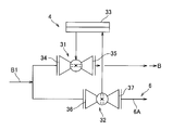
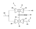
- a modification of the blocking means 4 will be described with reference to FIGS. 6 and 7 includes a first two-way valve 31, a second two-way valve 32, and driving means (switching means) for driving the first two-way valve 31 and the second two-way valve 32.
- the actuator 33 The first two-way valve 31 is provided with a first port 34 to which the downstream pipe B1 from the compression means 2 is connected, and a second port 35 to which the gas delivery line B toward the downstream process is connected. .
- the second two-way valve 32 is provided with a first port 36 to which the downstream pipe B1 from the compression means 2 is connected, and a third port 37 to which the reflux pipe 6A of the reflux means 6 is connected.
- the first two-way valve 31 and the second two-way valve 32 may be a ball valve having a spherical valve body or a butterfly valve having a rotating valve body, and the opening and closing thereof are switched by driving of the actuator 33. It is like that.
- the actuator 33 shown in FIG. 6 is provided with a mechanical link mechanism therein, and is driven to open and close in synchronization with the valve bodies of the first two-way valve 31 and the second two-way valve 32.
- the actuator 33 shown in FIG. 7 is connected to a stem 38 that connects the valve bodies of the first two-way valve 31 and the second two-way valve 32, and the first two-way valve 31 and the second two-way are connected via the stem 38.
- the valve body of the valve 32 is driven to open and close in synchronization.
- the actuator 33 shown in FIG. 7 has an urging means such as a spring inside, and is configured to drive the stem 38 by the urging force.
- the actuator 33 opens the first two-way valve 31 and closes the second two-way valve 32 so that the compression means 2 passes through the downstream pipe B1.
- the sent gas is sent from the first two-way valve 31 to the downstream process via the gas delivery line B (first state).
- the actuator 33 by closing the first two-way valve 31 and opening the second two-way valve 32 by the actuator 33, the gas sent from the compression means 2 via the downstream pipe B1 It is recirculated from the valve 32 to the recirculation means 6 via the recirculation pipe 6A (second state). That is, the first state and the second state are switched by driving the actuator 33.
- the driving force is lost because the valve bodies of the first two-way valve 31 and the second two-way valve 32 are biased to the second state by the biasing force of the biasing means. Even in this case, the gas is refluxed to the reflux means 6.
- the blocking means 4 shown in FIG. 8 includes a tubular (cylinder-shaped) valve body 51 and an actuator 52 that is a drive means (switching means) that rotates the valve body 51 around its axis. Yes.
- the valve body 51 is provided with a first port 53 on one axial side (the lower side in FIG. 8), and a second port 54 is provided at a predetermined position in the circumferential direction.
- a third port 55 is provided at a position deviated.
- the valve body 51 is rotationally driven by the actuator 52, whereby the gas is sent from the second port 54 to the downstream process via the gas delivery line B, and the reflux is sent from the third port 55 via the reflux pipe 6A.
- the second state in which the gas is refluxed to the means 6 is switched.
Landscapes
- Engineering & Computer Science (AREA)
- General Engineering & Computer Science (AREA)
- Mechanical Engineering (AREA)
- Taps Or Cocks (AREA)
- Filling Or Discharging Of Gas Storage Vessels (AREA)
- Multiple-Way Valves (AREA)
- Pipeline Systems (AREA)
Abstract
制御の複雑化やシステムの複雑化、大型化を招くことなく、システム内におけるガス圧力上昇を適切に抑制することができるガス圧送装置を提供する。 ガス圧送装置(1)は、上流プロセスから供給されたガスを圧縮して下流プロセスへ送出する圧縮手段(2)と、圧縮手段よりも下流側に設けられて下流プロセスへのガスを遮断する遮断手段(4)と、遮断手段で遮断したガスを圧縮手段の上流側へ還流させる還流手段(6)と、を備え、遮断手段は、圧縮手段からのガスを導入する一次側の第一ポート(11)と、下流プロセスに向かってガスを導出する二次側の第二ポート(12)と、還流手段に向かってガスを導出する二次側の第三ポート(13)と、二次側へのガスの導出を第二ポートと第三ポートとのいずれかに切り替える切替手段(14)と、を有して構成されている。
Description
本発明は、上流プロセスから供給された各種ガスを圧縮機等で圧縮して下流プロセスへ送出するガス圧送装置に関する。
従来、例えば、液化ガス(液化天然ガスLNGや液化石油ガスLPGなど)の製造設備や貯留設備、受入設備において、原料ガスや冷媒ガス、ボイルオフガス、供給ガス等の各種ガスは、低圧から高圧まで適切な圧力となるように昇圧されてから各種配管経路を用いて搬送されている。このようなシステム内におけるガス圧の過大な上昇による機器の破損を防止するために、経路内に配置された安全弁を作動させてガスをフレア設備に送り、フレア設備でガスを燃焼させて廃棄する方法が利用されている(例えば、特許文献1参照)。
特許文献1に記載された液化ガス貯蔵設備は、液化ガス貯槽で貯蔵した液化ガスをポンプにより気化器に供給し、気化器で液化ガスを加熱して気化させ、気化したガスを気化ガス供給ラインより需要側ガスラインに送出する。液化ガス取り出しラインには第1遮断弁が設けられ、この第1遮断弁の下流側には、液化ガス貯槽に液化ガスを戻す液化ガス戻しラインが接続され、液化ガス戻しラインには第2遮断弁が設けられている。気化ガス供給ラインには、上流側から順に、安全弁と、需要側遮断弁と、スタック遮断弁とが設けられ、スタック遮断弁にはスタックラインを介してフレアスタックが接続されている。
この設備では、通常運転時には第1遮断弁と需要側遮断弁とが開放され、安全弁、スタック遮断弁、第2遮断弁が閉鎖されているが、例えば、需要側ガスラインに異常が発生すると、第1遮断弁と需要側遮断弁とが遮断されてポンプが停止されるとともに、スタック遮断弁、第2遮断弁が開放される。また、安全弁も開放されることにより、気化ガス供給ラインの圧力が過大に上昇して機器が破損することが防止される。さらに、気化ガスが液化ガス戻しラインを経由して液化ガス貯槽に戻されることにより、ライン内で気化したガスを安全弁から放出する量や、フレアスタックで処理する気化ガスの量を減少させるようになっている。
しかしながら、特許文献1に記載された従来のシステムでは、ライン内のガス圧力が上昇した場合に、2つの遮断弁を閉鎖し、その上で、通常閉鎖しているスタック遮断弁と第2遮断弁とを開放する必要がある。このため、複数の機器を同時または順次適切に作動させる必要があることから、その制御が複雑化するとともに、複数の機器を作動させるための多くの補機類も必要となり、システム構成が複雑かつ大型化するという問題がある。
本発明の目的は、制御の複雑化やシステムの複雑化、大型化を招くことなく、システム内におけるガス圧力上昇を適切に抑制することができるガス圧送装置を提供することにある。
本発明のガス圧送装置は、上流プロセスから供給されたガスを圧縮して下流プロセスへ送出する圧縮手段と、前記圧縮手段よりも下流側に設けられて下流プロセスへのガスを遮断する遮断手段と、前記遮断手段で遮断したガスを前記圧縮手段の上流側へ還流させる還流手段と、を備え、前記遮断手段は、前記圧縮手段からのガスを導入する一次側の第一ポートと、下流プロセスに向かってガスを導出する二次側の第二ポートと、前記還流手段に向かってガスを導出する二次側の第三ポートと、二次側へのガスの導出を前記第二ポートと前記第三ポートとのいずれかに切り替える切替手段と、を有して構成されていることを特徴とする。
以上のような本発明によれば、遮断手段が第一ポート、第二ポート、第三ポート、および切替手段を有し、通常運転時においては第二ポートから下流プロセスに向かってガスを導出し、非常時には切替手段によって二次側へのガスの導出を第三ポートに切り替え、第二ポートから下流プロセスへのガスを遮断するとともに、第三ポートから還流手段に向かってガスを導出し、このガスを圧縮手段の上流側へ還流させることができる。従って、遮断手段において二次側のポートを第二ポートから第三ポートに切り替えるだけの簡単な動作によって、圧縮手段の下流側におけるガス圧の上昇を抑制することができる。また従来のように複数の遮断弁等を同時または適切な順序で作動させる複雑な制御が不要になるとともに、複数の遮断弁等やこれらに付随する補機類を省略することができるので、システム構成を簡単化して装置の小型化ならびにシステムの故障に関わる要素の削減を図ることができる。
この際、本発明のガス圧送装置では、前記遮断手段は、前記切替手段による切り替えの途中段階において、前記第二ポートと前記第三ポートとの少なくともいずれかにガスを導出し続けることが好ましい。
この構成によれば、遮断手段の二次側のポートを第二ポートから第三ポートに切り替える途中の段階において、第二ポートと第三ポートとの少なくともいずれかにガスが導出され続けるので、ガスの流通を完全に止めることがなく、切替途中のガス圧上昇を抑制することができる。
また、本発明のガス圧送装置では、前記遮断手段は、ケース状の弁本体と、該弁本体の内部にて二次側が前記第二ポート位置と前記第三ポート位置との間で移動自在に支持された弁体と、該弁体を駆動する駆動手段と、を有する三方弁で構成され、前記弁本体に前記第一ポート、前記第二ポート、および前記第三ポートが設けられ、前記弁体と前記駆動手段とによって前記切替手段が構成され、前記弁体には、前記第一ポートに連通可能な第一連通部と、前記第二ポートおよび前記第三ポートのいずれかに連通可能な第二連通部と、前記第一連通部から前記第二連通部にガスを流通させるガス流通部と、が設けられ、前記駆動手段によって前記弁体が移動されることで、前記第一連通部が前記第一ポートに連通しかつ前記第二連通部が前記第二ポートに連通する第一状態と、前記第一連通部が前記第一ポートに連通しかつ前記第二連通部が前記第三ポートに連通する第二状態と、が切り替えられることが好ましい。
この構成によれば、遮断手段が弁本体と弁体と駆動手段とを有する三方弁で構成され、駆動手段による弁体の移動で、第二連通部が第二ポートに連通する第一状態と、第二連通部が第三ポートに連通する第二状態と、が切り替えられるので、切替動作を確実に実施させることができ、動作の信頼性を高めることができる。
さらに、本発明のガス圧送装置では、前記弁体は、球状に形成されるとともに前記弁本体に二次側が前記第二ポート位置と前記第三ポート位置との間で回動自在に支持され、前記第一連通部と前記第二連通部とが互いに前記弁体の径方向の反対側に位置し、前記ガス流通部が前記弁体を貫通して形成され、前記第一連通部は、前記弁体の回動に伴う移動範囲において前記第一ポートを包絡する開口面積を有し、前記第二連通部は、前記弁体の回動に伴う前記第一状態と前記第二状態との切替途中における前記第二ポートおよび前記第三ポートとの流路断面が、前記第一ポート側における流路断面の半分以上となる開口面積を有して構成されていることが好ましい。
この構成によれば、球状に形成された弁体の第一連通部は、その移動範囲において第一ポートを包絡する開口面積を有し、第二連通部は、第一状態と第二状態との切替途中における流路断面が第一ポート側の半分以上となる開口面積を有して構成されているので、切替途中においてもガスの流通を完全に止めることがなく、通常運転時の少なくとも半分以上のガス流路面積を確保することができ、切替途中のガス圧上昇を最小限に留めることができる。
また、本発明のガス圧送装置では、前記遮断手段は、前記圧縮手段と下流プロセスとの間に設けられる第1二方弁と、前記圧縮手段と前記還流手段との間に設けられる第2二方弁と、該第1二方弁および第2二方弁を駆動する駆動手段と、を有して構成され、前記第1二方弁に前記第一ポートおよび前記第二ポートが設けられ、前記第2二方弁に前記第一ポートおよび前記第三ポートが設けられ、前記切替手段を構成する前記駆動手段によって、前記第1二方弁を開くとともに前記第2二方弁を閉じることで前記第二ポートから下流プロセスへガスを送出させる第一状態と、前記第1二方弁を閉じるとともに前記第2二方弁を開くことで前記第三ポートから前記還流手段へガスを還流させる第二状態と、が切り替えられることが好ましい。
この構成によれば、遮断手段が第1二方弁と第2二方弁を有し、駆動手段によって第1二方弁を開いて第2二方弁を閉じる第一状態と、第1二方弁を閉じて第2二方弁を開く第二状態と、が切り替えられるので、システムの複雑化、大型化を招くことなく、ガス圧力上昇を適切に抑制することができる。
また、本発明のガス圧送装置では、前記遮断手段は、管状の弁体と、該弁体を軸回りに回転駆動する駆動手段と、を有して構成され、前記弁体には、軸方向一方側に前記第一ポートが設けられ、周方向所定位置に前記第二ポートが設けられ、この第二ポートと周方向にずれた位置に前記第三ポートが設けられ、前記切替手段を構成する前記駆動手段によって前記弁体を回転駆動することで、前記第二ポートから下流プロセスへガスを送出させる第一状態と、前記第三ポートから前記還流手段へガスを還流させる第二状態と、が切り替えられることが好ましい。
この構成によれば、遮断手段が管状の弁体を有し、駆動手段によって弁体回転駆動することによって第一状態と第二状態とが切り替えられるので、切替動作を確実に実施させて信頼性を高めることができる。
以上のような本発明のガス圧送装置によれば、制御の複雑化やシステムの複雑化、大型化を招くことなく、システム内におけるガス圧力上昇を適切に抑制することができる。
以下、本発明の実施形態を図面に基づいて説明する。本実施形態のガス圧送装置1は、例えば、液化天然ガス(LNG)の製造設備や貯留設備、受入設備等に設置され、上流プロセスから下流プロセスへガスを圧送するものである。ここで、圧送する対象のガスとしては、原料ガスである天然ガスや、天然ガスを冷却するための冷媒ガス、天然ガスが気化して発生するボイルオフガス、利用系へ送出するための供給ガスなど、各種のガスが例示できる。
ガス圧送装置1には、図1に示すように、上流プロセスからガスを供給するガス供給ラインAと、圧縮したガスを下流プロセスに送出するガス送出ラインBと、が接続されている。ここで、上流プロセスや下流プロセスとしては、対象ガスの種類や、設備内の位置に応じて様々であるが、一例として、対象ガスが供給ガスの場合には、上流プロセスは気化プロセスであり、下流プロセスはガス需要設備への送出プロセスである。
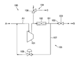
ここで、本実施形態のガス圧送装置1に対し、改良前のガス圧送装置100について、図5に基づいて説明する。ガス圧送装置100には、ガス圧送装置1と同様に、ガス供給ラインAと、ガス送出ラインBと、が接続されている。このガス圧送装置100は、ガス供給ラインAから供給されたガスを圧縮する圧縮手段101と、圧縮手段101で圧縮したガスを冷却する冷却手段102と、冷却手段102で冷却したガスの下流プロセスへの送出を遮断する遮断手段103と、圧縮手段101と冷却手段102との間に接続されてガスを大気放出する放出手段104と、冷却手段102と遮断手段103との間から圧縮手段101の上流側に接続されるサージ防止手段105と、を備えて構成されている。
圧縮手段101は、上流プロセスからの上流配管A1を通して供給されたガスを圧縮し、圧縮したガスを下流配管B1を通して下流プロセスに送出するものであって、例えば、遠心式圧縮機が用いられている。冷却手段102は、下流配管B1の途中に設けられ、圧縮手段101で昇圧されて加熱されたガスを冷却するものであって、例えば、空冷式のエアフィンクーラーが用いられている。
遮断手段103は、下流配管B1における冷却手段102よりも下流側に設けられ、下流プロセスへのガスの送出を遮断するものであって、例えば、ガス遮断弁が用いられている。このガス遮断弁は、図示しない制御手段によって駆動制御され、通常運転時には解放され、非常時には閉止されるようになっている。
放出手段104は、遮断手段103によって下流プロセスへのガスの送出が遮断された場合に、圧縮手段101が停止するまでの間、下流配管B1内部のガス圧が上昇するのを抑制するためにガスを大気に放出するものである。この放出手段104は、ガス圧が所定値を超えた場合に開放する安全弁106を有し、この安全弁106の二次側には、ガスを燃焼させて大気に放出するフレアスタックCが接続されている。
サージ防止手段105は、圧縮手段101の運転開始時や停止時におけるガス圧の変動や、下流プロセスにおけるガス需要量に基づきガス圧に差が生じることなどによって、圧縮手段101内に発生するサージ状態が圧縮手段101に悪影響を及ぼすのを防止するためのものである。このサージ防止手段105は、下流配管B1における冷却手段102と遮断手段103との間から圧縮手段101の上流側の上流配管A1に接続される循環配管107と、この循環配管107の途中に設けられて圧縮手段101のサージ状態を防止するアンチサージ弁108と、を有して構成されている。
以上のように、改良前のガス圧送装置100によれば、下流プロセスの異常(例えば、火災等)を検出して遮断手段103が作動し、これによって下流プロセスへのガスの送出が遮断された非常時において、圧縮手段101の稼動が停止するまでの間に下流配管B1内部のガス圧が上昇すると、放出手段104の安全弁106が開放し、フレアスタックCを介してガスを大気放出することで、下流配管B1のガス圧が過大に増大することが防止されるようになっている。
しかしながら、改良前のガス圧送装置100では、遮断手段103によって下流配管B1のガスの流れを止めてから、放出手段104の安全弁106が開放するまでの間に時間的なずれが生じることから、下流配管B1内のガス圧が上昇することになる。また、システムの安全性確保のためには、安全弁106およびフレアスタックCが確実に作動することが必須であり、遮断手段103、安全弁106およびフレアスタックCという複数の機器における動作の確実性を担保しておく必要がある。このため、各機器の保守やメンテナンスなどに多大な労力を要するという課題がある。また、改良前のガス圧送装置100では、非常時にフレアスタックCで燃焼させたガスを大気放出することから、環境負荷が増加してしまうという課題もある。
以上のような改良前のガス圧送装置100に対し、本実施形態のガス圧送装置1における改良点について、以下、図1~4に基づいて詳しく説明する。ガス圧送装置1は、圧縮手段2と、冷却手段3と、遮断手段4と、サージ防止手段5と、還流手段6と、を備えて構成されている。このガス圧送装置1において、遮断手段4および還流手段6がガス圧送装置100から改良されている。一方、圧縮手段2、冷却手段3およびサージ防止手段5は、圧縮手段101、冷却手段102およびサージ防止手段105と略同様のものが利用されている。
遮断手段4は、圧縮手段2からのガスを導入する一次側の第一ポート11と、下流プロセスに向かってガスを導出する二次側の第二ポート12と、還流手段6に向かってガスを導出する二次側の第三ポート13と、二次側へのガスの導出を第二ポート12と第三ポート13とのいずれかに切り替える切替手段14と、を有した三方弁10で構成されている。
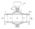
三方弁10は、図2、3に示すように、ケース状の弁本体15と、この弁本体15の内部にて二次側が第二ポート12位置と第三ポート13位置との間で回動自在に支持された球状の弁体16と、この弁体16を回動させるように駆動する駆動手段としてのアクチュエーター17と、を有したボール弁で構成されている。弁体16およびアクチュエーター17によって切替手段14が構成され、アクチュエーター17は、図示しない制御手段によって駆動制御されるようになっている。また、弁本体15に第一ポート11、第二ポート12、および第三ポート13が設けられており、これらの各ポート11,12,13は、それぞれ略円筒状であり略同一の開口面積を有して形成されている。
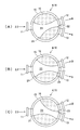
弁体16は、第一ポート11に連通可能な第一連通部21と、第二ポート12および第三ポート13のいずれかに連通可能な第二連通部22と、第一連通部21から第二連通部22にガスを流通させるガス流通部23と、を有して形成されている。第一連通部21と第二連通部22とは、互いに弁体16の径方向の反対側に位置し、ガス流通部23が弁体16を貫通して形成されている。このような弁体16は、アクチュエーター17の駆動によって弁体16が回動されることで、図3(A)に示すように、第二ポート12に第二連通部22が連通した第一状態と、図3(C)に示すように、第三ポート13に第二連通部22が連通した第二状態と、が切り替えられるようになっている。
第一連通部21は、弁体16の回動方向に沿って長い楕円形または長円形に形成され、その開口面積が弁体16の回動に伴う移動範囲において第一ポート11を包絡する大きさに形成されている。ガス流通部23は、第一連通部21から徐々に径が縮小されて形成されるものの、その中間にて最小内径となる位置での流路断面が第一ポート11の開口面積と同等以上となるように形成されている。
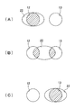
第二連通部22は、図4に示すように、弁体16の回動方向に沿って長い楕円形または長円形に形成され、図4(A)に示す第一状態では、第二ポート12に連通し、図4(C)に示す第二状態では、第三ポート13に連通するようになっている。また、第二連通部22の開口面積は、図4(B)に示す第一状態と第二状態との切替途中において、第二ポート12および第三ポート13との流路断面(図中ハッチングで示す部分)が、第一ポート11側における流路断面(第一ポート11の開口面積)の半分以上となる大きさに形成されている。すなわち、第二連通部22は、第一状態と第二状態との切替途中においても塞がれることがなく、第二ポート12および第三ポート13の少なくともいずれかと必ず連通されるように構成されている。
サージ防止手段5は、前記サージ防止手段105と同様に、下流配管B1における冷却手段3と遮断手段4との間から圧縮手段2の上流側の上流配管A1に接続される循環配管5Aと、この循環配管5Aの途中に設けられて圧縮手段2内のサージ状態を防止するアンチサージ弁5Bと、を有して構成されている。還流手段6は、遮断手段4の第三ポート13に接続されるとともに、サージ防止手段5の循環配管5Aにおけるアンチサージ弁5Bの二次側に接続される還流配管6Aを有して構成されている。この還流手段6は、遮断手段4が第二状態に切り替えられた際に、下流配管B1内のガスを還流配管6Aに受け入れ、サージ防止手段5の循環配管5Aを介して圧縮手段2の上流側の上流配管A1へガスを還流させるようになっている。
以上のガス圧送装置1において、通常運転時には、図3(A)、図4(A)に示すように、遮断手段4の弁体16は、第一連通部21が第一ポート11に連通するとともに、第二連通部22が第二ポート12に連通した第一状態とされ、第一ポート11から第二ポート12に向かってガスが流通するようになっている。従って、上流プロセスからガス供給ラインAで供給されて圧縮手段2によって圧縮されたガスは、下流配管B1および遮断手段4を介してガス送出ラインBで下流プロセスへ送出されることとなる。
一方、非常時において、制御手段により遮断手段4のアクチュエーター17を駆動して弁体16が回動され、図3(C)、図4(C)に示すように、第二連通部22が第三ポート13に連通した第二状態とされると、下流プロセスへの送出が遮断される。この場合、遮断手段4に達したガスは、第三ポート13から還流手段6の還流配管6Aへ送られるとともに、循環配管5Aを介して圧縮手段2の上流側の上流配管A1へ還流することとなる。
このように遮断手段4の弁体16を第一状態から第二状態へ切り替える切替途中において、図3(B)、図4(B)に示すように、第二連通部22が第二ポート12と第三ポート13とに跨った状態となり、この状態では、第一ポート11から第二ポート12および第三ポート13の両方に向かってガスが流通するようになっている。換言すると、切替途中においても第二連通部22が塞がれることがなく、第二ポート12および第三ポート13の少なくともいずれかにガスを導出し続けるように構成されている。このような切替途中においても、流通されるガスの流量は、第一状態および第二状態の半分以上が確保されるようになっている。
以上のような本実施形態のガス圧送装置1によれば、以下のような効果がある。すなわち、非常時には遮断手段4を第二状態に切り替え、第二ポート12から下流プロセスへのガスを遮断するとともに、第三ポート13から還流手段6に向かってガスを導出して還流させることができるので、遮断手段4においてアクチュエーター17の駆動によって弁体16を回動させるだけの簡単な動作によって、下流配管B1におけるガス圧の上昇を抑制することができる。また、複数の遮断弁等を同時または適切な順序で作動させる複雑な制御が不要になるとともに、複数の遮断弁等やこれらに付随する補機類を省略することができるので、システム構成を簡単化して装置の小型化を図り、システムの信頼性を高めることができる。また、機器構成が簡単化、小型化できることで、保守やメンテナンスに要する手間やコストを削減することができる。
また、遮断手段4を第一状態から第二状態に切り替える途中の段階において、第二ポート12および第三ポート13の少なくともいずれかにガスが導出され続けるので、ガスの流通を完全に止めることがなく、切替途中のガス圧上昇を抑制することができる。さらに、切替途中においても、流通されるガスの流量は、第一状態および第二状態の半分以上が確保されるので、ガス圧の上昇を最小限に留めることができ、圧縮手段2への悪影響を防止することができる。また、遮断手段4が三方弁10で構成され、アクチュエーター17による弁体16の回動によって第一状態と第二状態とが切り替えられるので、この切替動作を確実に実施させることができ、動作の信頼性を高めることができる。
また、非常時には遮断手段4の第三ポート13から還流手段6に向かってガスを還流させることで、改良前のガス圧送装置100のような放出手段104を設ける必要がなくなるので、装置構成をさらに簡単化することができる。また、ガスを大気放出する必要がないことから、外部への環境負荷を低減させることができる。さらに、放出手段104が省略できることで、設備の敷地面積の縮小を図ることができる。
なお、本発明は、前記実施形態に限定されるものではなく、本発明の目的が達成できる他の構成等を含み、以下に示すような変形等も本発明に含まれる。例えば、前記実施形態では、液化天然ガス(LNG)の製造設備や貯留設備、受入設備等に設置される気化ガス供給ラインにおけるガス圧送装置について説明したが、本発明は、液化天然ガスに限らず、液化石油ガス(LPG)や液化窒素、液化酸素、液体水素など任意の液化ガスの製造設備等におけるガス圧送装置として利用可能である。また、ガス圧送装置としては、気化ガス供給ラインに限らず、各設備にガスを受け入れる際のガス搬送ラインに利用されてもよいし、LNG貯蔵タンク内のLNGが気化することで発生するボイルオフガス(BOG)を処理するBOG処理ラインに利用されてもよい。また、液化天然ガス製造設備において、天然ガスを液化する際に用いる各種冷媒ガスの循環システム中に利用されてもよい。
また、前記実施形態では、遮断手段4が三方弁10を有して構成されていたが、本発明における遮断手段は、前記実施形態で説明した三方弁10に限らず、同等の機能を有した機器に置き換え可能である。また、また、三方弁としては、前記実施形態のようなボール弁に限らず、円柱状や円盤状の弁体が回動可能に設けられたものでもよいし、適宜な形状の弁体がスライド可能に設けられたものでもよい。さらに、弁体は1つに限らず、第一ポート、第二ポート、第三ポートのそれぞれに別体の弁体が設けられたものでもよい。また、前記実施形態では、還流手段6の還流配管6Aがサージ防止手段5の循環配管5Aに接続されていたが、圧縮手段2の上流側の上流配管A1に接続されていてもよい。
このような遮断手段4の変形例について、図6~8に基づいて説明する。図6、7に示す遮断手段4は、第1二方弁31と、第2二方弁32と、これらの第1二方弁31および第2二方弁32を駆動する駆動手段(切替手段)であるアクチュエーター33と、を有して構成されている。第1二方弁31には、圧縮手段2からの下流配管B1が接続される第一ポート34と、下流プロセスへ向かうガス送出ラインBが接続される第二ポート35と、が設けられている。第2二方弁32には、圧縮手段2からの下流配管B1が接続される第一ポート36と、還流手段6の還流配管6Aが接続される第三ポート37と、が設けられている。第1二方弁31および第2二方弁32は、球状の弁体を有したボール弁でもよいし、回動する弁体を有したバタフライ弁でもよく、アクチュエーター33の駆動によって開閉が切り替えられるようになっている。
図6に示すアクチュエーター33は、その内部に機械式のリンク機構が設けられ、第1二方弁31および第2二方弁32の弁体を同期させて開閉駆動するものである。図7に示すアクチュエーター33は、第1二方弁31および第2二方弁32の弁体を連結するステム38に接続され、このステム38を介して第1二方弁31および第2二方弁32の弁体を同期させて開閉駆動するものである。また、図7に示すアクチュエーター33は、内部にばね等の付勢手段を有し、その付勢力によってステム38を駆動するように構成されている。
図6,7に示す遮断手段4では、通常運転時において、アクチュエーター33によって、第1二方弁31を開くとともに第2二方弁32を閉じることで、圧縮手段2から下流配管B1を介して送られたガスは、第1二方弁31からガス送出ラインBを介して下流プロセスへ送出される(第一状態)。一方、非常時において、アクチュエーター33によって、第1二方弁31を閉じるとともに第2二方弁32を開くことで、圧縮手段2から下流配管B1を介して送られたガスは、第2二方弁32から還流配管6Aを介して還流手段6へ還流される(第二状態)。すなわち、アクチュエーター33の駆動によって第一状態と第二状態とが切り替えられるようになっている。なお、図7に示すアクチュエーター33では、付勢手段の付勢力によって第1二方弁31および第2二方弁32の弁体を第二状態に付勢しているため、駆動力が失われた場合であってもガスを還流手段6へ還流させるように構成されている。
図8に示す遮断手段4は、管状(シリンダ状)の弁体51と、この弁体51を軸回りに回転駆動する駆動手段(切替手段)であるアクチュエーター52と、を有して構成されている。弁体51には、軸方向一方側(図8の下側)に第一ポート53が設けられ、周方向所定位置に第二ポート54が設けられ、この第二ポート54と周方向かつ軸方向にずれた位置に第三ポート55が設けられている。アクチュエーター52によって弁体51が回転駆動されることで、第二ポート54からガス送出ラインBを介して下流プロセスへガスを送出させる第一状態と、第三ポート55から還流配管6Aを介して還流手段6へガスを還流させる第二状態と、が切り替えられる。
その他、本発明を実施するための最良の構成、方法などは、以上の記載で開示されているが、本発明は、これに限定されるものではない。すなわち、本発明は、主に特定の実施形態に関して特に図示され、且つ、説明されているが、本発明の技術的思想および目的の範囲から逸脱することなく、以上述べた実施形態に対し、形状、材質、数量、その他の詳細な構成において、当業者が様々な変形を加えることができるものである。従って、上記に開示した形状、材質などを限定した記載は、本発明の理解を容易にするために例示的に記載したものであり、本発明を限定するものではないから、それらの形状、材質などの限定の一部、もしくは全部の限定を外した部材の名称での記載は、本発明に含まれるものである。
1 ガス圧送装置
2 圧縮手段
3 冷却手段
4 遮断手段
5 サージ防止手段
6 還流手段
10 三方弁
11 第一ポート
12 第二ポート
13 第三ポート
14 切替手段
15 弁本体
16 弁体
17 アクチュエーター(駆動手段)
21 第一連通部
22 第二連通部
23 ガス流通部
2 圧縮手段
3 冷却手段
4 遮断手段
5 サージ防止手段
6 還流手段
10 三方弁
11 第一ポート
12 第二ポート
13 第三ポート
14 切替手段
15 弁本体
16 弁体
17 アクチュエーター(駆動手段)
21 第一連通部
22 第二連通部
23 ガス流通部
Claims (6)
- 上流プロセスから供給されたガスを圧縮して下流プロセスへ送出する圧縮手段と、
前記圧縮手段よりも下流側に設けられて下流プロセスへのガスを遮断する遮断手段と、
前記遮断手段で遮断したガスを前記圧縮手段の上流側へ還流させる還流手段と、を備え、
前記遮断手段は、
前記圧縮手段からのガスを導入する一次側の第一ポートと、
下流プロセスに向かってガスを導出する二次側の第二ポートと、
前記還流手段に向かってガスを導出する二次側の第三ポートと、
二次側へのガスの導出を前記第二ポートと前記第三ポートとのいずれかに切り替える切替手段と、
を有して構成されていることを特徴とするガス圧送装置。 - 前記遮断手段は、前記切替手段による切り替えの途中段階において、前記第二ポートと前記第三ポートとの少なくともいずれかにガスを導出し続けることを特徴とする請求項1に記載のガス圧送装置。
- 前記遮断手段は、ケース状の弁本体と、該弁本体の内部にて二次側が前記第二ポート位置と前記第三ポート位置との間で移動自在に支持された弁体と、該弁体を駆動する駆動手段と、を有する三方弁で構成され、
前記弁本体に前記第一ポート、前記第二ポート、および前記第三ポートが設けられ、
前記弁体と前記駆動手段とによって前記切替手段が構成され、
前記弁体には、前記第一ポートに連通可能な第一連通部と、前記第二ポートおよび前記第三ポートのいずれかに連通可能な第二連通部と、前記第一連通部から前記第二連通部にガスを流通させるガス流通部と、が設けられ、
前記駆動手段によって前記弁体が移動されることで、前記第一連通部が前記第一ポートに連通しかつ前記第二連通部が前記第二ポートに連通する第一状態と、前記第一連通部が前記第一ポートに連通しかつ前記第二連通部が前記第三ポートに連通する第二状態と、が切り替えられることを特徴とする請求項1または2に記載のガス圧送装置。 - 前記弁体は、球状に形成されるとともに前記弁本体に二次側が前記第二ポート位置と前記第三ポート位置との間で回動自在に支持され、
前記第一連通部と前記第二連通部とが互いに前記弁体の径方向の反対側に位置し、前記ガス流通部が前記弁体を貫通して形成され、
前記第一連通部は、前記弁体の回動に伴う移動範囲において前記第一ポートを包絡する開口面積を有し、
前記第二連通部は、前記弁体の回動に伴う前記第一状態と前記第二状態との切替途中における前記第二ポートおよび前記第三ポートとの流路断面が、前記第一ポート側における流路断面の半分以上となる開口面積を有して構成されていることを特徴とする請求項3に記載のガス圧送装置。 - 前記遮断手段は、前記圧縮手段と下流プロセスとの間に設けられる第1二方弁と、前記圧縮手段と前記還流手段との間に設けられる第2二方弁と、該第1二方弁および第2二方弁を駆動する駆動手段と、を有して構成され、
前記第1二方弁に前記第一ポートおよび前記第二ポートが設けられ、前記第2二方弁に前記第一ポートおよび前記第三ポートが設けられ、
前記切替手段を構成する前記駆動手段によって、前記第1二方弁を開くとともに前記第2二方弁を閉じることで前記第二ポートから下流プロセスへガスを送出させる第一状態と、前記第1二方弁を閉じるとともに前記第2二方弁を開くことで前記第三ポートから前記還流手段へガスを還流させる第二状態と、が切り替えられることを特徴とする請求項1または2に記載のガス圧送装置。 - 前記遮断手段は、管状の弁体と、該弁体を軸回りに回転駆動する駆動手段と、を有して構成され、
前記弁体には、軸方向一方側に前記第一ポートが設けられ、周方向所定位置に前記第二ポートが設けられ、この第二ポートと周方向にずれた位置に前記第三ポートが設けられ、
前記切替手段を構成する前記駆動手段によって前記弁体を回転駆動することで、前記第二ポートから下流プロセスへガスを送出させる第一状態と、前記第三ポートから前記還流手段へガスを還流させる第二状態と、が切り替えられることを特徴とする請求項1または2に記載のガス圧送装置。
Priority Applications (3)
| Application Number | Priority Date | Filing Date | Title |
|---|---|---|---|
| US15/559,965 US10544903B2 (en) | 2015-03-24 | 2016-03-14 | Gas pressure feed device |
| US16/708,671 US20200109821A1 (en) | 2015-03-24 | 2019-12-10 | Gas pressure feed device |
| US16/708,654 US20200109820A1 (en) | 2015-03-24 | 2019-12-10 | Gas pressure feed device |
Applications Claiming Priority (2)
| Application Number | Priority Date | Filing Date | Title |
|---|---|---|---|
| JP2015-060775 | 2015-03-24 | ||
| JP2015060775A JP2018084242A (ja) | 2015-03-24 | 2015-03-24 | ガス圧送装置 |
Related Child Applications (3)
| Application Number | Title | Priority Date | Filing Date |
|---|---|---|---|
| US15/559,965 A-371-Of-International US10544903B2 (en) | 2015-03-24 | 2016-03-14 | Gas pressure feed device |
| US16/708,671 Division US20200109821A1 (en) | 2015-03-24 | 2019-12-10 | Gas pressure feed device |
| US16/708,654 Division US20200109820A1 (en) | 2015-03-24 | 2019-12-10 | Gas pressure feed device |
Publications (1)
| Publication Number | Publication Date |
|---|---|
| WO2016152609A1 true WO2016152609A1 (ja) | 2016-09-29 |
Family
ID=56978760
Family Applications (1)
| Application Number | Title | Priority Date | Filing Date |
|---|---|---|---|
| PCT/JP2016/057922 Ceased WO2016152609A1 (ja) | 2015-03-24 | 2016-03-14 | ガス圧送装置 |
Country Status (3)
| Country | Link |
|---|---|
| US (3) | US10544903B2 (ja) |
| JP (1) | JP2018084242A (ja) |
| WO (1) | WO2016152609A1 (ja) |
Cited By (3)
| Publication number | Priority date | Publication date | Assignee | Title |
|---|---|---|---|---|
| EP3306151A1 (en) * | 2016-10-05 | 2018-04-11 | Johnson Controls Technology Company | Valve member with improved fluid flow and control |
| CN109099313A (zh) * | 2018-08-31 | 2018-12-28 | 嘉兴智慧园区营运管理有限公司 | 一种智能自动化中心供氧系统 |
| CN115773468A (zh) * | 2022-10-21 | 2023-03-10 | 上海宇航系统工程研究所 | 一种用于气液连接器控制的供气气路及供气方法 |
Families Citing this family (9)
| Publication number | Priority date | Publication date | Assignee | Title |
|---|---|---|---|---|
| GB2573776B (en) * | 2018-05-16 | 2022-02-23 | Sav United Kingdom Ltd | A bypass valve assembly |
| FR3082599B1 (fr) * | 2018-06-15 | 2021-01-15 | Grtgaz | Procede et installation de rebours evolutif |
| US11541191B2 (en) * | 2019-05-09 | 2023-01-03 | Lexion Medical, Llc | Distributed flow path insufflation |
| DE102019212869A1 (de) * | 2019-08-27 | 2021-03-04 | Vitesco Technologies GmbH | Fluidventil |
| US11854839B2 (en) | 2020-04-15 | 2023-12-26 | Mks Instruments, Inc. | Valve apparatuses and related methods for reactive process gas isolation and facilitating purge during isolation |
| DE102020207925A1 (de) * | 2020-06-25 | 2021-12-30 | Vitesco Technologies GmbH | Mischventil |
| CN111750163B (zh) * | 2020-07-15 | 2022-05-27 | 浙江挺宇流体设备股份有限公司 | 一种紧急切断气动控制系统 |
| US12589233B2 (en) * | 2021-09-23 | 2026-03-31 | Engineered Medical Systems, Inc. | Ball valve for use in a respiration circuit and a respiration circuit including a ball valve |
| WO2023235214A1 (en) * | 2022-06-01 | 2023-12-07 | Mks Instruments, Inc. | Valve apparatuses and related methods for reactive process gas isolation and facilitating purge during isolation |
Citations (3)
| Publication number | Priority date | Publication date | Assignee | Title |
|---|---|---|---|---|
| JPS52131223A (en) * | 1976-04-26 | 1977-11-04 | Akinobu Tsuruta | Ball type branch valve |
| JPH09170592A (ja) * | 1995-12-18 | 1997-06-30 | Ishikawajima Harima Heavy Ind Co Ltd | Lng基地におけるガス流量制御装置 |
| JP2014181629A (ja) * | 2013-03-19 | 2014-09-29 | Suzuki Motor Corp | 車両用エンジンの排気ガス還流装置 |
Family Cites Families (9)
| Publication number | Priority date | Publication date | Assignee | Title |
|---|---|---|---|---|
| US164448A (en) * | 1875-06-15 | Improvement in faucets | ||
| US759688A (en) * | 1903-09-03 | 1904-05-10 | George W Frazier | Sander for locomotives. |
| US1807900A (en) * | 1927-07-18 | 1931-06-02 | Glenn O Dougherty | Fluid flow control fixture |
| US1807085A (en) * | 1928-07-25 | 1931-05-26 | Tridex Corp | Two-way valve |
| US2393464A (en) * | 1942-02-17 | 1946-01-22 | Albert J Granberg | Bulk plant receiving recorder |
| US3817265A (en) * | 1972-06-16 | 1974-06-18 | T Ambler | Anti-pollution compressor control system |
| US5251663A (en) * | 1992-08-14 | 1993-10-12 | The United States Of America As Represented By The Administrator Of The National Aeronautics And Space Administration | High-temperature, high-pressure oxygen metering valve |
| JPH11210991A (ja) | 1998-01-29 | 1999-08-06 | Ishikawajima Harima Heavy Ind Co Ltd | 液化ガス気化器昇圧防止装置 |
| US9404241B1 (en) * | 2013-08-29 | 2016-08-02 | Roland Joseph Davantes | Waste water diverter apparatus |
-
2015
- 2015-03-24 JP JP2015060775A patent/JP2018084242A/ja active Pending
-
2016
- 2016-03-14 WO PCT/JP2016/057922 patent/WO2016152609A1/ja not_active Ceased
- 2016-03-14 US US15/559,965 patent/US10544903B2/en active Active
-
2019
- 2019-12-10 US US16/708,654 patent/US20200109820A1/en not_active Abandoned
- 2019-12-10 US US16/708,671 patent/US20200109821A1/en not_active Abandoned
Patent Citations (3)
| Publication number | Priority date | Publication date | Assignee | Title |
|---|---|---|---|---|
| JPS52131223A (en) * | 1976-04-26 | 1977-11-04 | Akinobu Tsuruta | Ball type branch valve |
| JPH09170592A (ja) * | 1995-12-18 | 1997-06-30 | Ishikawajima Harima Heavy Ind Co Ltd | Lng基地におけるガス流量制御装置 |
| JP2014181629A (ja) * | 2013-03-19 | 2014-09-29 | Suzuki Motor Corp | 車両用エンジンの排気ガス還流装置 |
Cited By (7)
| Publication number | Priority date | Publication date | Assignee | Title |
|---|---|---|---|---|
| EP3306151A1 (en) * | 2016-10-05 | 2018-04-11 | Johnson Controls Technology Company | Valve member with improved fluid flow and control |
| CN107917246A (zh) * | 2016-10-05 | 2018-04-17 | 江森自控科技公司 | 具有改进的流体流动和控制的阀构件 |
| US10465803B2 (en) | 2016-10-05 | 2019-11-05 | Johnson Controls Technology Company | Multipurpose valve assembly tool |
| US10844966B2 (en) | 2016-10-05 | 2020-11-24 | Johnson Controls Technology Company | Valve member with improved fluid flow and control |
| US11002368B2 (en) | 2016-10-05 | 2021-05-11 | Johnson Controls Technology Company | Valve assembly with equal percentage flow control |
| CN109099313A (zh) * | 2018-08-31 | 2018-12-28 | 嘉兴智慧园区营运管理有限公司 | 一种智能自动化中心供氧系统 |
| CN115773468A (zh) * | 2022-10-21 | 2023-03-10 | 上海宇航系统工程研究所 | 一种用于气液连接器控制的供气气路及供气方法 |
Also Published As
| Publication number | Publication date |
|---|---|
| US20180073684A1 (en) | 2018-03-15 |
| US20200109820A1 (en) | 2020-04-09 |
| US10544903B2 (en) | 2020-01-28 |
| JP2018084242A (ja) | 2018-05-31 |
| US20200109821A1 (en) | 2020-04-09 |
Similar Documents
| Publication | Publication Date | Title |
|---|---|---|
| JP2018084242A (ja) | ガス圧送装置 | |
| KR101588663B1 (ko) | 선박의 연료가스 공급장치 | |
| US11971044B2 (en) | Compression system and method of controlling a compression system | |
| JP2021525347A (ja) | 燃料電池タンクの温度圧力を解放するタンク装置 | |
| CN111536420B (zh) | 一种液态乙烷管道检修后安全充装系统与充装方法 | |
| JP6829560B2 (ja) | 緊急遮断弁装置 | |
| JP2016079894A (ja) | 熱回収システム | |
| EP2222944B1 (en) | Sequential combustion firing system for a fuel system of a gas turbine engine | |
| CN109404720B (zh) | 用于动力机械、设备或交通工具的液化气的汽化组分的冷却 | |
| JP2025092665A (ja) | 二重燃料エンジンの窒素供給システム及びその制御方法 | |
| JP2019035502A5 (ja) | ||
| CN105658570A (zh) | 用于输送加压气流的装载组件和使用在装载组件中的切换系统 | |
| KR101703502B1 (ko) | 압축기 작동 방법 및 이를 위한 장치 | |
| US10443513B2 (en) | Emergency shutoff device and emergency shutoff system provided with same | |
| PL245306B1 (pl) | Urządzenie do sprężania odparowanego gazu | |
| JP7362467B2 (ja) | 圧縮機システム | |
| KR20170110198A (ko) | 가스 연료 공급 제어를 위한 가스 밸브 유닛 | |
| KR102520465B1 (ko) | 초저온 액화가스용 안전밸브 | |
| JP6515482B2 (ja) | 気化設備及び低温液化ガスの気化方法 | |
| CN117906065A (zh) | 缓冲设备、缓冲方法和空分系统 | |
| CN118208663A (zh) | 一种基于低温液化气体的供气装置及其控制方法 | |
| KR20250102618A (ko) | 이산화탄소 안전밸브설비, 동 설비를 이용한 이산화탄소 누설차단 방법 및 동 설비를 구비한 선박 | |
| CN120120484A (zh) | 一种不同类型全容罐共存的压力控制装置、方法及系统 | |
| JP2025120547A (ja) | 圧力調整弁 | |
| KR20240132090A (ko) | 액화가스 저장탱크의 쿨링 다운 방법 |
Legal Events
| Date | Code | Title | Description |
|---|---|---|---|
| 121 | Ep: the epo has been informed by wipo that ep was designated in this application |
Ref document number: 16768512 Country of ref document: EP Kind code of ref document: A1 |
|
| WWE | Wipo information: entry into national phase |
Ref document number: 15559965 Country of ref document: US |
|
| NENP | Non-entry into the national phase |
Ref country code: DE |
|
| 122 | Ep: pct application non-entry in european phase |
Ref document number: 16768512 Country of ref document: EP Kind code of ref document: A1 |
|
| NENP | Non-entry into the national phase |
Ref country code: JP |