WO2016152579A1 - 画像表示装置 - Google Patents
画像表示装置 Download PDFInfo
- Publication number
- WO2016152579A1 WO2016152579A1 PCT/JP2016/057761 JP2016057761W WO2016152579A1 WO 2016152579 A1 WO2016152579 A1 WO 2016152579A1 JP 2016057761 W JP2016057761 W JP 2016057761W WO 2016152579 A1 WO2016152579 A1 WO 2016152579A1
- Authority
- WO
- WIPO (PCT)
- Prior art keywords
- image
- light receiving
- light
- receiving unit
- adjustment
- Prior art date
- Legal status (The legal status is an assumption and is not a legal conclusion. Google has not performed a legal analysis and makes no representation as to the accuracy of the status listed.)
- Ceased
Links
Images


Classifications
-
- G—PHYSICS
- G02—OPTICS
- G02B—OPTICAL ELEMENTS, SYSTEMS OR APPARATUS
- G02B27/00—Optical systems or apparatus not provided for by any of the groups G02B1/00 - G02B26/00, G02B30/00
- G02B27/01—Head-up displays
-
- G—PHYSICS
- G09—EDUCATION; CRYPTOGRAPHY; DISPLAY; ADVERTISING; SEALS
- G09G—ARRANGEMENTS OR CIRCUITS FOR CONTROL OF INDICATING DEVICES USING STATIC MEANS TO PRESENT VARIABLE INFORMATION
- G09G3/00—Control arrangements or circuits, of interest only in connection with visual indicators other than cathode-ray tubes
- G09G3/20—Control arrangements or circuits, of interest only in connection with visual indicators other than cathode-ray tubes for presentation of an assembly of a number of characters, e.g. a page, by composing the assembly by combination of individual elements arranged in a matrix no fixed position being assigned to or needed to be assigned to the individual characters or partial characters
-
- G—PHYSICS
- G09—EDUCATION; CRYPTOGRAPHY; DISPLAY; ADVERTISING; SEALS
- G09G—ARRANGEMENTS OR CIRCUITS FOR CONTROL OF INDICATING DEVICES USING STATIC MEANS TO PRESENT VARIABLE INFORMATION
- G09G5/00—Control arrangements or circuits for visual indicators common to cathode-ray tube indicators and other visual indicators
- G09G5/36—Control arrangements or circuits for visual indicators common to cathode-ray tube indicators and other visual indicators characterised by the display of a graphic pattern, e.g. using an all-points-addressable [APA] memory
-
- G—PHYSICS
- G09—EDUCATION; CRYPTOGRAPHY; DISPLAY; ADVERTISING; SEALS
- G09G—ARRANGEMENTS OR CIRCUITS FOR CONTROL OF INDICATING DEVICES USING STATIC MEANS TO PRESENT VARIABLE INFORMATION
- G09G5/00—Control arrangements or circuits for visual indicators common to cathode-ray tube indicators and other visual indicators
- G09G5/36—Control arrangements or circuits for visual indicators common to cathode-ray tube indicators and other visual indicators characterised by the display of a graphic pattern, e.g. using an all-points-addressable [APA] memory
- G09G5/38—Control arrangements or circuits for visual indicators common to cathode-ray tube indicators and other visual indicators characterised by the display of a graphic pattern, e.g. using an all-points-addressable [APA] memory with means for controlling the display position
-
- H—ELECTRICITY
- H04—ELECTRIC COMMUNICATION TECHNIQUE
- H04N—PICTORIAL COMMUNICATION, e.g. TELEVISION
- H04N5/00—Details of television systems
- H04N5/74—Projection arrangements for image reproduction, e.g. using eidophor
-
- H—ELECTRICITY
- H04—ELECTRIC COMMUNICATION TECHNIQUE
- H04N—PICTORIAL COMMUNICATION, e.g. TELEVISION
- H04N9/00—Details of colour television systems
- H04N9/12—Picture reproducers
- H04N9/31—Projection devices for colour picture display, e.g. using electronic spatial light modulators [ESLM]
Definitions
- an image display device such as a head-up display uses a laser light source composed of the three primary colors of R, G, and B, creates a variety of colors by mixing each color, and displays a color image on the display surface.
- Projection display uses a laser light source composed of the three primary colors of R, G, and B, creates a variety of colors by mixing each color, and displays a color image on the display surface.
- the present invention has been made in view of such circumstances, and an object of the present invention is to provide an image display capable of effectively suppressing positional deviation and size variation of a projected image even when the wavelength of light emitted from a light source varies due to a temperature change. To provide an apparatus.
- the image adjustment unit performs projection based on the light reception results of the first light receiving unit for detecting the display position of the projection image and the second light receiving unit for detecting the size of the projection image. Since the image size is adjusted, the projection image magnification can be adjusted appropriately. Therefore, the image magnification can be adjusted appropriately even if the wavelength of light from the light source fluctuates due to temperature changes.
- the image adjusting unit of the present invention performs the size adjustment after adjusting the display position based on the detection result of the first light receiving unit. According to this configuration, since the size adjustment is performed after the adjustment of the display position of the projection image, the reference for the size adjustment of the projection image becomes clear and the size adjustment can be performed accurately.
- the image adjustment unit of the present invention compares the reference detection result of the first light receiving unit obtained in a state where the display position is adjusted with the first light receiving unit, and compares the projection image of the projection image.
- the display position is adjusted, the reference detection result of the second light receiving unit obtained in the size adjusted state is compared with the second light receiving unit, and the size of the projection image is adjusted.
- the reference detection result of the first light receiving unit obtained with the display position adjusted and the reference detection result of the second light receiving unit obtained with the size adjusted are used. Since the adjustment is performed, the display position and size of the projection image can be adjusted more accurately.
- the image adjusting unit of the present invention adjusts a phase modulation parameter of the image forming unit.
- the image adjustment unit adjusts the phase modulation parameter, the display position and size of the projection image can be adjusted by phase modulation.
- the first light receiving unit is arranged coaxially with the irradiation position of the zero-order light with respect to the rectangular region of the effective image display image
- the second light receiving unit is the first light receiving unit. It is arrange
- a color reference image for each of a plurality of colors emitted from the light source is received on the same axis as the first light receiving unit within a range irradiated with the modulated light of the adjustment image.
- a plurality of third light receiving parts are disposed. According to this configuration, the light intensity of the first light receiving unit can be accurately grasped within the irradiation range of the adjustment image and based on the color reference image. Further, by using a color reference image for each color as a reference, color misregistration can also be prevented.
- FIG. 1 is a functional block diagram of an image display device according to an embodiment of the present invention. It is a figure for demonstrating the principle in which a driver
- the image display device according to the present embodiment it is a diagram for explaining the arrangement of light receiving units including a first detection unit and a second detection unit.
- FIG. 1 is a functional block diagram of an image display apparatus 1 according to an embodiment of the present invention.
- FIG. 2 is a diagram for explaining the principle that the driver visually recognizes the virtual image.
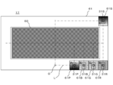
- FIG. 3 is a diagram for explaining the arrangement of the light receiving units including the first detection unit and the second detection unit in the image display apparatus according to the present embodiment.
- the image display device 1 according to the present embodiment is a head-up display that is used by being mounted on a vehicle (moving body).
- the image display device 1 includes, for example, a light emitting unit 11, an image forming unit 13, a Fourier transform lens 15, a light diffusing unit 17, a combiner 19, a light receiving unit 31, a light emission control unit 33, and an image adjustment unit 35.
- the light output of the laser of the light emitting unit 11 is controlled by the light emission control unit 33.
- the light emitting unit 11 of the present embodiment is controlled by the light emission control unit 33 by pulse width modulation (PWM) control or the light emission intensity itself of the laser.
- PWM pulse width modulation
- the image forming unit 13 forms a projection image by phase-modulating the laser light from the light emitting unit 11 based on the display image information generated by the image information generating unit 47, and transforms the hologram diffracted light corresponding thereto into a Fourier transform lens. 15 is irradiated.
- the image forming unit 13 has a function of forming a virtual lens on the LCOS based on the input parameters.
- the image forming unit 13 inputs the image adjustment information of the projection image from the image adjustment unit 35, and uses this as a parameter to adjust the display position and size of the projection image.
- the Fourier transform lens 15 Fourier transforms the hologram diffracted light from the image forming unit 13 to form an image on the light diffusion unit 17.
- the combiner 19 directs the light diffused from the light diffusing unit 17 and projects it onto the window shield glass 51.
- the window shield glass 51 is provided as a vehicle windshield.
- the combiner 19 projects a display image corresponding to the light from the light diffusing unit 17 toward the window shield glass 51, and reflects this projection image toward the driver's eyes.
- the projected image is formed as a virtual image 57 in front of the driver so that the driver can visually recognize the projected image.
- the angle of the combiner 19 can be freely adjusted to flexibly respond to changes in the driver's line-of-sight position.
- the light receiving unit 31 is, for example, a photodetector (PD) as a measurement device that converts light into electricity.
- a photodetector for example, a photovoltaic photodiode using a semiconductor pn junction can be cited.
- Photodiodes require that semiconductors absorb light and generate electron-hole pairs. Therefore, it is important to select a material for the photodiode that matches the wavelength of the laser beam to be measured.
- the first light receiving unit 31P is irradiated with an adjustment image 61P for adjusting the display position of the projection image.
- the adjustment image 61S for adjusting the size of the projection image is irradiated to the second light receiving unit 31S.
- the adjustment images 61P and 61S are images in which the intensity of light such as luminance continuously changes according to the position in the image. Examples of the adjustment images 61P and 61S include gradation images, but are not limited to the illustrated images.
- the adjustment images 61P and 61S of the present embodiment are set to R (red) that is easily affected by temperature, but B (blue) or G (green) may be adopted.
- the light emission control unit 33 inputs the light intensity of the light received by the light receiving unit 31, and feedback-controls the output of the light emitting unit 11 so that the light intensity becomes the specified light intensity.
- the designation of the light intensity is performed based on the output signal of the light receiving unit 31.
- the image memory 41 stores original image information of a display image.
- the original image information is, for example, JPEG.
- the parameter memory 43 stores initial information of parameter data for adjusting (setting) the luminance or the like of the original image information.
- the image memory 41 and the parameter memory 43 include a ROM, but may be other types of storage devices such as an SSD (Solid State Drive).
- the parameter setting unit 45 sets based on the parameter information read from the parameter memory 43, and outputs this to the image information generation unit 47.
- FIG. 3 is a diagram for explaining the arrangement of the light receiving units in the image display apparatus according to the present embodiment.
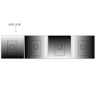
- FIG. 4 is a diagram for explaining an adjustment image irradiated on the first light receiving unit and the second light receiving unit in the image display apparatus according to the present embodiment.
- the image display device As shown in FIG. 1, in the image display device 1, light from the light emitting unit 11 enters the image forming unit 13. Further, the image information generation unit 47 adjusts the original image information read from the image memory 41 based on the parameters input from the parameter setting unit 45 to generate display image information.
- the image forming unit 13 forms a projection image by phase-modulating the laser light from the light emitting unit 11 based on the display image information generated by the image information generating unit 47, and transforms the hologram diffracted light into a Fourier transform lens. 15 is irradiated.
- the image forming unit 13 inputs the image adjustment information from the image adjusting unit 35, and uses this as a parameter to adjust the display position and the size of the projected image. Then, in the light diffusing unit 17, the hologram diffracted light is diffused, directed by the combiner 19, and applied to the window shield glass 51.
- the light projected from the combiner 19 onto the window shield glass 51 is reflected by the window shield glass 51 and reaches the viewpoint 55 of the driver (passenger).
- the driver can visually recognize a virtual image (virtual image display image) 57 obtained by enlarging an image corresponding to the light from the combiner 19 at a point in front of the window shield glass 51.
- the display surface of the image forming unit 13, the image formed on the diffusion region of the light diffusion unit 17, and the virtual image 57 are in a conjugate relationship.
- the wavelength of the laser beam emitted from the light emitting unit 11 may change due to factors such as the environmental temperature, and the projected image of the image forming unit 13 may be displaced.
- the wavelength of the laser beam is measured in advance. The wavelength measurement of the laser beam at the time of assembly is performed at a reference temperature.
- the laser used as the light emitting unit 11 includes a temperature adjusting device such as a Peltier element.
- a temperature adjusting device such as a Peltier element.
- the ambient temperature becomes equal to or higher than the set temperature, and the temperature adjusting device cannot adjust the temperature of the light emitting unit 11 appropriately, and as a result, the laser wavelength may not be adjusted.
- the wavelength variation of the red laser has temperature dependence. In this case, there is a possibility that the laser wavelength fluctuates with respect to the measurement wavelength at the time of assembling, which is a reference for the image magnification, and the projected image is cut off and the color shift occurs.
- an adjustment area 61 is set outside the rectangular light diffusion area 60 that is intermediately projected on the light diffusion section 17 and irradiated with an adjustment image for adjusting the positional deviation of the projected image. Yes.
- the adjustment area 61 is irradiated with a first light receiving portion 31P irradiated with an adjustment image 61P for adjusting the display position of the projection image, and an adjustment image 61S for adjusting the size of the projection image.
- Two light receiving portions 31S are disposed.
- the gradation direction may be set depending on which side of the rectangular area of the light diffusion area 60 is arranged. Specifically, it is preferable that the intensity of light such as luminance is continuously changed in a direction orthogonal to the side along which each light receiving unit is located. Actually, the intensity of light is grasped as the output voltage of the photodetector (PD) constituting the first light receiving unit 31P and the second light receiving unit 31S. The output voltages of the first light receiving unit 31P and the second light receiving unit 31S are input to the image adjusting unit 35.
- PD photodetector
- the image adjustment unit 35 receives input signals from the first light receiving unit 31P and the second light receiving unit 31S, and based on the light reception results of the first light receiving unit 31P and the second light receiving unit 31S, Image adjustment information for adjusting the display position and size is generated and output to the image forming unit 13. For example, the image adjustment unit 35 can adjust the display position and size of the projection image by adjusting the phase modulation parameter of the image forming unit 13.
- the image adjusting unit 35 first adjusts the display position based on the detection result of the first light receiving unit 31P, and then adjusts the size based on the detection result of the second light receiving unit 31S. Since the size adjustment is performed after the adjustment of the display position of the projection image, the reference for the size adjustment of the projection image becomes clear and the size adjustment can be performed accurately.
- the first light receiving portion 31P is disposed on the same axis L as the zero-order light irradiation position O. Since the display position of the projection image is adjusted based on the detection result of the first light receiving portion 31P coaxial with the zero-order light, the adjustment of the display position becomes accurate. As a result, the size adjustment of the projection image by the second light receiving unit 31S can be performed accurately with reference to the adjustment display position by the first light receiving unit 31P.
- the first light receiving unit 31P and the second light receiving unit 31S are arranged along two sides of the rectangular area of the effective image display image 60 within the irradiation range of the adjustment image. Further, the second light receiving unit 31S is arranged at a corner in the adjustment region 61 where the adjustment image is irradiated farther from the irradiation position O of the 0th-order light than the first light receiving unit 31P. Therefore, the first light receiving part 31P and the second light receiving part 31S exist on two axes intersecting each other. Therefore, by adjusting the display position of the projection image based on the detection result of the first light receiving unit 31P on one axis and adjusting the size of the projection image based on the adjustment display position, the size adjustment can be easily performed. Become.
- third light receiving portions 31 ⁇ / b> B, 31 ⁇ / b> G, and 31 ⁇ / b> R are disposed on the same axis L as the first detection portion 61 ⁇ / b> P.
- the third light receiving units 31B, 31G, and 31R receive the color reference images 61B, 61G, and 61R for the respective colors.
- the color reference images 61B, 61G, and 61R for each color are set to a light intensity of 50%, for example.
- the first light reception By preparing color reference images 61B, 61G, and 61R serving as references for R (red), G (green), and B (blue), and comparing them with the color reference images 61B, 61G, and 61R, the first light reception
- the projection image display position based on the detection result of the unit 31P and the projection image size based on the detection result of the second light receiving unit 31S are adjusted.
- the adjustment result after being mounted on a vehicle or the like can be used as the reference detection result.
- the received light intensity in the image 61P and the received light intensity in the adjustment image 61S are stored. In particular, since the light reception intensity of the adjustment image 61S changes when the image magnification changes, the image magnification is corrected in accordance with the change.
- the reference detection result of the first light receiving unit 31P after the display position adjustment is compared with the first light receiving unit 31P to adjust the display position of the projection image, thereby adjusting the display position of the projection image.
- the reference detection result of the second light receiving unit 31S after the size adjustment is compared with the second light receiving unit 31S, and the size of the projection image is adjusted, thereby adjusting the size of the projection image. Adjustment is more accurate. Therefore, based on the color reference images 61B, 61G, and 61R, the intensity of light such as luminance detected by the first light receiving unit 31P can be accurately grasped, and color misregistration can also be prevented.
- the first light receiving unit 31P for the image adjusting unit 35 to detect the display position of the projected image and the first for detecting the size of the projected image is adjusted based on the light reception result with the two light receiving units 31S. Therefore, the projection image position and the projection image magnification can be adjusted easily and accurately.
- the image display device 1 performs size adjustment after adjusting the display position of the projected image. Therefore, the reference for adjusting the size of the projected image becomes clear, and the size can be adjusted accurately.
- the image display device 1 compares the reference detection result of the first light receiving unit after the display position adjustment with the first light receiving unit, and adjusts the display position of the projection image. Further, after adjusting the display position, the reference detection result of the second light receiving unit and the second light receiving unit are compared, and the size of the projection image is adjusted. Therefore, the display position and size adjustment of the projection image become more accurate.
- the first light receiving unit 31P and the second light receiving unit 31S are irradiated with the adjustment images 61P and 61S, and the adjustment images 61P and 61S are located at positions in the image. Accordingly, the gradation image has a continuously changing intensity. Therefore, according to the image display device 1 according to the present embodiment, it is possible to easily grasp the intensity of light applied to the first light receiving unit 31P and the second light receiving unit 31S. This facilitates adjustment of the display position and size of the projected image.
- the image display device 1 includes the first light receiving unit 31P and the second light receiving unit within the irradiation range 61 of the adjustment image and along the two intersecting sides of the rectangular region 60 of the effective image display image.
- the light receiving part 31S is arranged. Therefore, according to the image display device 1 according to the present embodiment, the first light receiving unit 31P and the second light receiving unit 31S exist on two axes intersecting, and the projection image based on the adjustment display position of the projection image is displayed. Size adjustment is easy.
- the first light receiving unit 31P is disposed coaxially with the irradiation position O of the zero-order light. Therefore, according to the image display device 1 according to the present embodiment, the adjustment of the display position of the projection image is accurate with the 0th order light as a reference. As a result, the projection image size can be accurately adjusted based on the adjustment display position.
- the image display device 1 is a light receiving unit that receives the color reference images 61B, 61G, and 61R for each color within the irradiation range of the adjustment image and coaxially with the first light receiving unit 31P. 31B, 31G, and 31R are provided. Therefore, according to the image display device 1 according to the present embodiment, it is possible to accurately grasp the light intensity of the first light receiving unit 31P based on the color reference images 61B, 61G, and 61R for each color. Further, by using the color reference images 61B, 61G, 61R for each color as a reference, it is possible to prevent color misregistration.
- the image display device 1 according to the present embodiment can adjust the display position and size of the projected image without controlling the temperature as a reference for wavelength measurement during assembly. Therefore, according to the image display apparatus 1 according to the present embodiment, the operating temperature range is expanded, and the service to the user can be improved. Further, the performance of the Peltier element used for laser temperature adjustment can be relaxed, and the manufacturing cost can be reduced.
- the third light receiving units 31B, 31G, and 31R for receiving the color reference images 61B, 61G, and 61R for the respective colors within the irradiation range of the adjustment image are B (blue), G (green) and R (red) are provided in this order. This is because the larger the color wavelength, the larger the image is projected, but the order of arrangement of the third light receiving portions 31B, 31G, 31R is not limited.
Landscapes
- Engineering & Computer Science (AREA)
- Physics & Mathematics (AREA)
- General Physics & Mathematics (AREA)
- Computer Hardware Design (AREA)
- Theoretical Computer Science (AREA)
- Multimedia (AREA)
- Signal Processing (AREA)
- Optics & Photonics (AREA)
- Transforming Electric Information Into Light Information (AREA)
- Video Image Reproduction Devices For Color Tv Systems (AREA)
- Controls And Circuits For Display Device (AREA)
Abstract
温度変化による波長変動に基づく画像倍率の変動が生じても、画像位置および画像倍率を調整することができ、色ずれをも防止することができる画像表示装置を提供する。画像表示装置1は、光源から出射された光に応じた投影画像を形成する画像形成部13と、画像形成部13によって画像形成された変調光の照射範囲に設けられ、投影画像の表示位置を検出するための第1の受光部31Pと、画像形成部13によって画像形成された変調光の照射範囲に設けられ、投影画像のサイズを検出するための第2の受光部31Sと、第1の受光部31Pと第2の受光部31Sとの受光結果を基に、投影画像のサイズ調整を行う画像調整部35とを有する。
Description
本発明は、表示面に画像を投影表示する画像表示装置に関するものである。
従来より、ヘッドアップディスプレイなどの画像表示装置では、R,G,Bの光の三原色からなるレーザ光源を用い、それぞれの色を混ぜ合わせて多種多様な色を作成し、表示面にカラー画像を投影表示している。
この種の画像表示装置に関連する技術としては、例えば、ホログラム光学素子で回折し
た光の強さを、前記複数色ごとに検出する検出部と、該検出部の検出結果に基づいて、表示部の発光強度を複数色ごとに調整する調整部と、を備えた映像表示装置が開示されている(特許文献1参照)。特許文献1の映像表示装置は、検出部が映像光に寄与されない光を受光できる位置に設けられ、ホログラム光学素子の色バランスを調整するために、光源に含まれる複数色ごとに光の強さを検出する検出部の検出結果に基づいて、光源の発光強度を調整する。
た光の強さを、前記複数色ごとに検出する検出部と、該検出部の検出結果に基づいて、表示部の発光強度を複数色ごとに調整する調整部と、を備えた映像表示装置が開示されている(特許文献1参照)。特許文献1の映像表示装置は、検出部が映像光に寄与されない光を受光できる位置に設けられ、ホログラム光学素子の色バランスを調整するために、光源に含まれる複数色ごとに光の強さを検出する検出部の検出結果に基づいて、光源の発光強度を調整する。
ところで、特許文献1の技術では、複数色ごとの光の輝度を検出し、光源の温度や経時変化による輝度の変動を抑えている。しかし、特許文献1の技術は、輝度の変動を抑えているのみであり、温度変化に伴って生じる出射光の波長変動による画像倍率のばらつきや、画像倍率のばらつきによって生じる色ずれ等を防止することはできなかった。
本発明はかかる事情に鑑みてなされたものであり、その目的は、光源からの出射光の波長が温度変化により変動した場合でも、投影画像の位置ずれ、サイズ変動を効果的に抑制できる画像表示装置を提供することにある。
本発明に係る画像表示装置は、光源から出射された光に応じた投影画像を形成する画像形成部と、前記画像形成部によって画像形成された変調光の照射範囲に設けられ、前記投影画像の表示位置を検出するための第1の受光部と、前記画像形成部によって画像形成された変調光の照射範囲に設けられ、前記投影画像のサイズを検出するための第2の受光部と、前記第1の受光部と前記第2の受光部との受光結果を基に、前記投影画像のサイズ調整を行う画像調整部とを有する。
この構成によれば、画像調整部が投影画像の表示位置を検出するための第1の受光部と、投影画像のサイズを検出するための第2の受光部との受光結果を基に、投影画像のサイズ調整を行うので、投影画像倍率を適切に調整することができる。
そのため、光源からの光の波長が温度変化によって変動しても、画像倍率を適切に調整できる。
そのため、光源からの光の波長が温度変化によって変動しても、画像倍率を適切に調整できる。
好適には本発明の記画像調整部は、前記第1の受光部の検出結果を基に表示位置の調整を行ってから、前記サイズ調整を行う。
この構成によれば、投影画像の表示位置の調整を行ってからサイズ調整を行うので、投影画像のサイズ調整の基準が明確となり、サイズ調整を正確に行うことができる。
この構成によれば、投影画像の表示位置の調整を行ってからサイズ調整を行うので、投影画像のサイズ調整の基準が明確となり、サイズ調整を正確に行うことができる。
好適には本発明の前記画像調整部は、表示位置調整された状態で得られた前記第1の受光部の基準検出結果と、前記第1の受光部とを比較して、前記投影画像の表示位置の調整を行い、サイズ調整された状態で得られた前記第2の受光部の基準検出結果と、前記第2の受光部とを比較して、前記投影画像のサイズの調整を行う。
この構成によれば、表示位置調整された状態で得られた第1の受光部の基準検出結果と、サイズ調整された状態で得られた前記第2の受光部の基準検出結果とを用いて調整を行うため、投影画像の表示位置およびサイズの調整がより正確となる。
好適には本発明の前記画像調整部は、前記画像形成部の位相変調パラメータを調整する。この構成によれば、画像調整部が位相変調パラメータを調整するので、投影画像の表示位置およびサイズを位相変調により調整することが可能となる。
好適には本発明の画像表示装置では、前記投影画像には、有効イメージ表示画像と、その外側に表示される調整用画像とを有し、前記調整用画像は、前記第1の受光部および前記第2の受光部に照射され、画像内の位置に応じて輝度が連続的に変化している画像であることが好ましい。
この構成によれば、第1の受光部および第2の受光部に調整用画像が照射され、該調整用画像は画像内の位置に応じて輝度が連続的に変化している画像であるので、第1の受光部および第2の受光部に照射される光の強度がどの程度であるかを容易に把握することができる。これにより、投影画像の表示位置およびサイズの調整が容易となる。
この構成によれば、第1の受光部および第2の受光部に調整用画像が照射され、該調整用画像は画像内の位置に応じて輝度が連続的に変化している画像であるので、第1の受光部および第2の受光部に照射される光の強度がどの程度であるかを容易に把握することができる。これにより、投影画像の表示位置およびサイズの調整が容易となる。
好適には本発明では、前記第1の受光部と前記第2の受光部とは、前記照射範囲内の前記調整用画像の変調光が照射される範囲内において、前記有効イメージ表示画像の変調光が照射される矩形領域の交差する2辺に沿って配置されている。
この構成によれば、調整用画像の照射範囲内であって、有効イメージ表示画像の矩形領域の交差する2辺に沿って第1の受光部と第2の受光部とが配置されているので、第1の受光部と第2の受光部とが交差する2軸に存在し、投影画像の調整表示位置に基づいた投影画像のサイズ調整が容易となる。
この構成によれば、調整用画像の照射範囲内であって、有効イメージ表示画像の矩形領域の交差する2辺に沿って第1の受光部と第2の受光部とが配置されているので、第1の受光部と第2の受光部とが交差する2軸に存在し、投影画像の調整表示位置に基づいた投影画像のサイズ調整が容易となる。
好適には本発明では、前記第1の受光部は前記有効イメージ表示画像の矩形領域に対して0次光の照射位置と同軸上に配設され、前記第2の受光部は、前記第1の受光部よりも前記0次光の照射位置から離れた位置に配設されている。
この構成によれば、0次光の照射位置と同軸上に第1の受光部が配設されているので、0次光を基準として投影画像の表示位置の調整が正確となる。その結果、調整表示位置を基準とした投影画像のサイズ調整も正確に行うことができる。
この構成によれば、0次光の照射位置と同軸上に第1の受光部が配設されているので、0次光を基準として投影画像の表示位置の調整が正確となる。その結果、調整表示位置を基準とした投影画像のサイズ調整も正確に行うことができる。
好適には本発明では、前記調整用画像の変調光が照射される範囲内の前記第1の受光部と同軸上には、前記光源から出射される複数の色毎の色基準画像をそれぞれ受光する複数の第3の受光部が配設されている。
この構成によれば、調整用画像の照射範囲内であって、当該色基準画像に基づいて、第1の受光部の光の強度を正確に把握することができる。また、色ごとの色基準画像を基準として用いることにより、色ずれをも防止することができる。
この構成によれば、調整用画像の照射範囲内であって、当該色基準画像に基づいて、第1の受光部の光の強度を正確に把握することができる。また、色ごとの色基準画像を基準として用いることにより、色ずれをも防止することができる。
本発明によれば、光源からの光の波長が温度変化により変動した場合でも、投影画像の位置ずれ、サイズ変動を効果的に抑制できる。
以下、図1から図3を参照して、本発明の実施形態に係る画像表示装置について説明する。
図1は本発明の実施形態に係る画像表示装置1の機能ブロック図である。図2は運転者が虚像を視認する原理を説明するための図である。図3は本実施形態に係る画像表示装置において、第1の検出部および第2の検出部を含む受光部の配置を説明するための図である。
本実施形態に係る画像表示装置1は、車両(移動体)に搭載されて用いられるヘッドアップディスプレイである。
図1は本発明の実施形態に係る画像表示装置1の機能ブロック図である。図2は運転者が虚像を視認する原理を説明するための図である。図3は本実施形態に係る画像表示装置において、第1の検出部および第2の検出部を含む受光部の配置を説明するための図である。
本実施形態に係る画像表示装置1は、車両(移動体)に搭載されて用いられるヘッドアップディスプレイである。
図1に示すように、画像表示装置1は、例えば、発光部11、画像形成部13、フーリエ変換レンズ15、光拡散部17、コンバイナ19、受光部31、発光制御部33、画像調整部35、画像メモリ41、パラメータメモリ43、パラメータ設定部45、画像情報生成部47を有する。
発光部11は、例えば、半導体に電流を流してレーザ発振させる素子としてのレーザデバイス(LD)である。半導体レーザは、半導体の構成元素によって発振する周波数、すなわちレーザ光の色が決まる。本実施形態の発光部11は、例えば、虚像表示のためのR(赤),G(緑),B(青)の光の3原色のレーザで構成されている。発光部11は、各レーザからの光を画像形成部13に照射する。
発光部11としては、LED素子を用いてもよい。
発光部11としては、LED素子を用いてもよい。
発光部11のレーザの光出力は発光制御部33によって制御される。本実施形態の発光部11は、発光制御部33によってパルス幅変調(PWM:Pulse Width Modulation)制御か、または、レーザの発光強度そのものを制御される。
画像形成部13は、画像情報生成部47で生成された表示画像情報に基づいて、発光部11からのレーザ光を位相変調して投影画像を形成し、それに応じたホログラム回折光をフーリエ変換レンズ15に照射する。
画像形成部13は、入力したパラメータを基にLCOS上に仮想レンズを形成する機能を有している。画像形成部13は、投影画像の画像調整情報を画像調整部35から入力し、これをパラメータとして用いて投影画像の表示位置調整およびサイズ調整を行う。
画像形成部13は、入力したパラメータを基にLCOS上に仮想レンズを形成する機能を有している。画像形成部13は、投影画像の画像調整情報を画像調整部35から入力し、これをパラメータとして用いて投影画像の表示位置調整およびサイズ調整を行う。
本実施形態の画像形成部13は、例えば、LCOS(Liquid Crystal on Silicon)である。
ここで、LCOSは、一般的にはシリコンのCMOS基板上にマトリクス状にMOS型トランジスタや画素電極を設け、このCMOS基板と対向配置した基板の画素電極対向面に光学的に透明の共通電極を設け、これらの基板間に封入された液晶層からなる反射型液晶表示素子である。
画像形成部13は、LCOSに代えて透過型LCD等を用いてもよい。
ここで、LCOSは、一般的にはシリコンのCMOS基板上にマトリクス状にMOS型トランジスタや画素電極を設け、このCMOS基板と対向配置した基板の画素電極対向面に光学的に透明の共通電極を設け、これらの基板間に封入された液晶層からなる反射型液晶表示素子である。
画像形成部13は、LCOSに代えて透過型LCD等を用いてもよい。
画像形成部13から出射された変調光が中間像として結像する光拡散部17の照射範囲には、有効イメージ表示画像の変調光が照射される矩形の光拡散領域60と、その外側に光拡散されない調整用画像の変調光が照射される調整領域61とを有する(図3参照)。
フーリエ変換レンズ15は、画像形成部13からのホログラム回折光をフーリエ変換して光拡散部17に結像させる。
光拡散部17は、フーリエ変換レンズ15を介して入射したホログラム回折光を光拡散領域60において光拡散する。本実施形態の光拡散部17は、例えば、光学用ディフューザである。光学用ディフューザは、光を面全体に均一に拡げ、ホットスポットを低減する。光学用ディフューザは、イメージングアプリケーションにおけるスクリーンやターゲットとして最適である。
コンバイナ19は、光拡散部17からの光拡散された光を指向してウィンドウシールドガラス51に投影する。ウィンドウシールドガラス51は車両のフロントガラスとして設けられている。
コンバイナ19は、図1及び図2に示すように、光拡散部17からの光に応じた表示像を、ウィンドウシールドガラス51に向けて投影し、この投影画像を運転者の目の方向に反射させることによって当該投影画像を虚像57として運転者の前方に結像させて運転者に投影画像を視認させる。コンバイナ19は、運転者の視線位置の変化に柔軟に対応するため角度が自由に調節可能となっている。
受光部31は、例えば、光を電気に変換する計測用デバイスとしてのフォトディテクタ(PD)である。代表的なフォトディテクタとしては、例えば、半導体のpn接合を利用した光起電力型のフォトダイオードが挙げられる。
フォトダイオードは、半導体に光が吸収されて電子-ホール対が発生することを要する。したがって、フォトダイオードの材料は、測定したいレーザ光の波長にあった材料を選択することが重要である。
フォトダイオードは、半導体に光が吸収されて電子-ホール対が発生することを要する。したがって、フォトダイオードの材料は、測定したいレーザ光の波長にあった材料を選択することが重要である。
本実施形態では、複数個の受光部31が設けられている。複数個の受光部31は、図3に示すように、光拡散部17に投影される中間画像の調整用画像の変調光が照射される調整領域61内に設けられている。調整領域61内には、第1の受光部31Pと第2の受光部31Sが配設されている。
第1の受光部31Pは、投影画像の表示位置を検出するための受光部である。第2の受光部31Sは、投影画像のサイズを検出するための受光部である。
第1の受光部31Pは、投影画像の表示位置を検出するための受光部である。第2の受光部31Sは、投影画像のサイズを検出するための受光部である。
調整領域61内において、第1の受光部31Pと第2の受光部31Sは、有効イメージ光が照射される光拡散領域60の矩形領域の2辺に沿って配置されている。
第1の受光部31Pは、光拡散領域60に対して0次光の照射位置Oと同軸上に配設されている。本実施形態では、0次光の照射位置Oと第1の受光部31Pは、光拡散領域60の下辺と平行軸上に配設されている。
第1の受光部31Pは、光拡散領域60に対して0次光の照射位置Oと同軸上に配設されている。本実施形態では、0次光の照射位置Oと第1の受光部31Pは、光拡散領域60の下辺と平行軸上に配設されている。
第2の受光部31Sは、第1の受光部31Pよりも、0次光の照射位置Oから離れた位置に配設されている。本実施形態の第2の受光部31Sは、調整領域61内の角部に配設されているが、角部に限定されない。
第1の受光部31Pには、投影画像の表示位置を調整するための調整用画像61Pが照射される。他方、第2の受光部31Sには、投影画像のサイズを調整するための調整用画像61Sが照射される。
調整用画像61P,61Sは、画像内の位置に応じて輝度等の光の強度が連続的に変化している画像である。調整用画像61P,61Sとしては、例えば、グラデーション画像が挙げられるが、例示の画像に限定されない。
本実施形態の調整用画像61P,61Sは、温度の影響を受けやすいR(赤)に設定されているが、B(青)やG(緑)を採用しても構わない。
調整用画像61P,61Sは、画像内の位置に応じて輝度等の光の強度が連続的に変化している画像である。調整用画像61P,61Sとしては、例えば、グラデーション画像が挙げられるが、例示の画像に限定されない。
本実施形態の調整用画像61P,61Sは、温度の影響を受けやすいR(赤)に設定されているが、B(青)やG(緑)を採用しても構わない。
また、調整用画像が照射される調整領域61内において、第1の受光部31Pと同軸上には、各色ごとの色基準画像を受光する第3の受光部31B,31G,31Rが配設されている。第3の受光部31Bは、B(青)のレーザ光の波長に対応している。第3の受光部31Gは、G(緑)のレーザ光の波長に対応している。受光部31Rは、R(赤)のレーザ光の波長に対応している。
第3の受光部31B,31G,31Rには、それぞれ各色ごとの色基準画像61B,61G,61Rが照射される。各色ごとの色基準画像61B,61G,61Rの輝度(光強度)は、適宜設定される。
第3の受光部31B,31G,31Rには、それぞれ各色ごとの色基準画像61B,61G,61Rが照射される。各色ごとの色基準画像61B,61G,61Rの輝度(光強度)は、適宜設定される。
発光制御部33は、受光部31が受光した光の光強度を入力し、当該光強度が指定された光強度になるように発光部11の出力をフィードバック制御する。
当該光強度の指定は、受光部31の出力信号に基づいて行われる。
当該光強度の指定は、受光部31の出力信号に基づいて行われる。
画像調整部35は、第1の受光部31Pと第2の受光部31Sとの受光結果を基に、投影画像の表示位置およびサイズを調整するための画像調整情報を生成し、これを画像形成部13に出力する。画像調整部35は、例えば、画像形成部13の位相変調パラメータを調整する。位置調整制御35の処理については後に詳細に説明する。
画像メモリ41は、表示画像の原画像情報を記憶する。当該原画像情報は、例えばJPEGである。
パラメータメモリ43は、原画像情報の輝度等を調整(設定)するためのパラメータデータの初期情報を記憶する。
画像メモリ41及びパラメータメモリ43としては、ROMが挙げられるが、SSD(Solid State Drive)等の他の形式の記憶装置であってもよい。
パラメータメモリ43は、原画像情報の輝度等を調整(設定)するためのパラメータデータの初期情報を記憶する。
画像メモリ41及びパラメータメモリ43としては、ROMが挙げられるが、SSD(Solid State Drive)等の他の形式の記憶装置であってもよい。
パラメータ設定部45は、パラメータメモリ43から読み出したパラメータ情報を基に設定し、これを画像情報生成部47に出力する。
画像情報生成部47は、パラメータ設定部45から入力したパラメータを基に、画像メモリ41から読み出した原画像情報の輝度情報等を調整して表示画像情報を生成し、これを画像形成部13に出力する。
次に、図1から図4を参照して、本実施形態に係る画像表示装置1の動作を説明する。
図3は本実施形態に係る画像表示装置において、受光部の配置を説明するための図である。図4は本実施形態に係る画像表示装置において、第1の受光部および第2の受光部に照射される調整用画像を説明するための図である。
図3は本実施形態に係る画像表示装置において、受光部の配置を説明するための図である。図4は本実施形態に係る画像表示装置において、第1の受光部および第2の受光部に照射される調整用画像を説明するための図である。
図1に示すように、画像表示装置1では、発光部11からの光が画像形成部13に入射する。
また、画像情報生成部47において、パラメータ設定部45から入力したパラメータを基に、画像メモリ41から読み出した原画像情報を調整して表示画像情報が生成される。
そして、画像形成部13が、画像情報生成部47で生成された表示画像情報に基づいて、発光部11からのレーザ光を位相変調して投影画像を形成し、そのホログラム回折光をフーリエ変換レンズ15に照射する。
また、画像情報生成部47において、パラメータ設定部45から入力したパラメータを基に、画像メモリ41から読み出した原画像情報を調整して表示画像情報が生成される。
そして、画像形成部13が、画像情報生成部47で生成された表示画像情報に基づいて、発光部11からのレーザ光を位相変調して投影画像を形成し、そのホログラム回折光をフーリエ変換レンズ15に照射する。
このとき、画像形成部13は、画像調整情報を画像調整部35から入力し、これをパラメータとして用いて投影画像の表示位置調整およびサイズ調整を行う。
そして、光拡散部17において、ホログラム回折光が拡散され、コンバイナ19で指向されてウィンドウシールドガラス51に照射される。
そして、光拡散部17において、ホログラム回折光が拡散され、コンバイナ19で指向されてウィンドウシールドガラス51に照射される。
図2に示すように、コンバイナ19からウィンドウシールドガラス51に投射された光は、ウィンドウシールドガラス51で反射して運転者(搭乗者)の視点55に到達する。運転者は、ウィンドウシールドガラス51の前方の地点において、コンバイナ19からの光に応じた画像を拡大した虚像(虚像表示像)57として視認することができる。
ここで、画像形成部13の表示面と、光拡散部17の拡散領域上に形成される画像と、虚像57とが共役関係にある。
ここで、画像形成部13の表示面と、光拡散部17の拡散領域上に形成される画像と、虚像57とが共役関係にある。
ところで、環境温度等の要因で発光部11で発光するレーザ光の波長が変化して、画像形成部13の投影画像に位置ずれが生じることがある。画像表示装置1の車両への組立時には、レーザ光の波長を予め測定している。この組立時のレーザ光の波長測定は、基準となる温度で行っている。
一方で車載環境下(例えば、周囲温度が-40℃~+75℃)においても、画像表示装置1を健全に動作させる必要がある。したがって、発光部11として用いるレーザには、ペルチェ素子等の温度調整装置を備えている。
しかし、真夏の炎天下等の高温環境下では、周囲が設定温度以上となり、温度調整装置では発光部11を適切な温度調整することが出来ず、結果としてレーザ波長を調整できない場合がある。特に赤色レーザの波長変動には、温度依存性があることが判っている。この場合、画像倍率の基準となる組立時の測定波長に対して、レーザ波長の変動が生じ、投影画像の角切れや色ずれが発生する可能性がある。
しかし、真夏の炎天下等の高温環境下では、周囲が設定温度以上となり、温度調整装置では発光部11を適切な温度調整することが出来ず、結果としてレーザ波長を調整できない場合がある。特に赤色レーザの波長変動には、温度依存性があることが判っている。この場合、画像倍率の基準となる組立時の測定波長に対して、レーザ波長の変動が生じ、投影画像の角切れや色ずれが発生する可能性がある。
図3に示すように、光拡散部17に中間投影される矩形の光拡散領域60の外側には、投影画像の位置ずれ調整のための調整用画像が照射される調整領域61が設定されている。
調整領域61には、投影画像の表示位置を調整するための調整用画像61Pが照射される第1の受光部31Pと、投影画像のサイズを調整するための調整用画像61Sが照射される第2の受光部31Sとが配設されている。
調整領域61には、投影画像の表示位置を調整するための調整用画像61Pが照射される第1の受光部31Pと、投影画像のサイズを調整するための調整用画像61Sが照射される第2の受光部31Sとが配設されている。
調整用画像61P,61Sは、画像内の位置に応じて輝度等の光の強度が連続的に変化するグラデーション画像として投影される。調整用画像61P,61Sとしてグラデーション画像を用いることで、第1の受光部31Pおよび第2の受光部31Sが調整用画像61P,61Sを受光すると、その受光強度から、グラデーションにより形成された連続した輝度変化のうち、何れの場所に第1の受光部Pおよび第2の受光部Sが位置しているかを明確に知ることができる。結果として、第1の受光部Pの検出結果から表示位置が、第2の受光部Sの検出結果からサイズが、どれだけ変動しているかを知ることができる。また、その際にグラデーションの向きは光拡散領域60の矩形領域の何れの辺に沿って配置されているかによって設定されると良い。具体的には各受光部が沿っている辺に対して直交する方向に連続して輝度等の光の強度が変化させると良い。
実際には、第1の受光部31Pおよび第2の受光部31Sを構成するフォトディテクタ(PD)の出力電圧として光の強度を把握する。これらの第1の受光部31Pおよび第2の受光部31Sの出力電圧は、画像調整部35に入力される。
実際には、第1の受光部31Pおよび第2の受光部31Sを構成するフォトディテクタ(PD)の出力電圧として光の強度を把握する。これらの第1の受光部31Pおよび第2の受光部31Sの出力電圧は、画像調整部35に入力される。
画像調整部35は、第1の受光部31Pおよび第2の受光部31Sの入力信号を受けて、第1の受光部31Pと第2の受光部31Sとの受光結果を基に、投影画像の表示位置およびサイズを調整するための画像調整情報を生成し、これを画像形成部13に出力する。画像調整部35は、例えば、画像形成部13の位相変調パラメータを調整することにより、投影画像の表示位置およびサイズを調整することが可能となる。
画像調整部35は、まず、第1の受光部31Pの検出結果を基に表示位置の調整を行った後に、第2の受光部31Sの検出結果を基にサイズ調整を行う。投影画像の表示位置の調整を行ってからサイズ調整を行うので、投影画像のサイズ調整の基準が明確となり、サイズ調整を正確に行うことができる。
図3に示すように、光拡散部17に結像する中間画像において、0次光の照射位置Oは、光軸として、光拡散領域60の下部のセンター位置に比較的容易に設定することができる。
第1の受光部31Pは0次光の照射位置Oと同軸L上に配設されている。この0次光と同軸上の第1の受光部31Pの検出結果を基に投影画像の表示位置を調整するので、表示位置の調整が正確となる。その結果、当該第1の受光部31Pによる調整表示位置を基準として、第2の受光部31Sによる投影画像のサイズ調整も正確に行うことができる。
第1の受光部31Pと第2の受光部31Sは、調整用画像の照射範囲内において、有効イメージ表示画像60の矩形領域の2辺に沿って配置されている。さらに、第2の受光部31Sは、第1の受光部31Pよりも、0次光の照射位置Oから離れた調整用画像が照射される調整領域61内の角部に配設されている。
したがって、第1の受光部31Pと第2の受光部31Sとが交差する2軸に存在することになる。よって、一方の軸上の第1の受光部31Pの検出結果を基に投影画像の表示位置を調整し、この調整表示位置に基づいて投影画像のサイズ調整を行うことにより、サイズ調整が容易となる。
したがって、第1の受光部31Pと第2の受光部31Sとが交差する2軸に存在することになる。よって、一方の軸上の第1の受光部31Pの検出結果を基に投影画像の表示位置を調整し、この調整表示位置に基づいて投影画像のサイズ調整を行うことにより、サイズ調整が容易となる。
また、図3に示すように、調整領域61内において、第1の検出部61Pと同軸L上には、第3の受光部31B,31G,31Rが配設されている。第3の受光部31B,31G,31Rは、それぞれ各色ごとの色基準画像61B,61G,61Rを受光する。各色ごとの色基準画像61B,61G,61Rは、例えば、50%の光強度に設定されている。
R(赤),G(緑),B(青)の各々の基準となる色基準画像61B,61G,61Rを準備し、色基準画像61B,61G,61Rと比較することで、第1の受光部31Pの検出結果に基づく投影画像の表示位置、および第2の受光部31Sの検出結果に基づく投影画像サイズの調整を行う。
R(赤),G(緑),B(青)の各々の基準となる色基準画像61B,61G,61Rを準備し、色基準画像61B,61G,61Rと比較することで、第1の受光部31Pの検出結果に基づく投影画像の表示位置、および第2の受光部31Sの検出結果に基づく投影画像サイズの調整を行う。
画像表示装置1の車両等への搭載後(組立時)には、投影画像の表示位置およびサイズの調整を行う。したがって、車両等への搭載後の調整結果を基準検出結果として用いることができる。製造時に投影画像の表示位置調整及び倍率調整を行い、その時のR(赤),G(緑),B(青)の各々の基準となる色基準画像61R,61G,61Bの受光強度、調整用画像61Pにおける受光強度、および調整用画像61Sにおける受光強度を記憶しておく。特に調整用画像61Sの受光強度は画像倍率が変動した際に変動するので、その変動に合わせて画像倍率を補正する。
すなわち、表示位置調整後の第1の受光部31Pの基準検出結果と第1の受光部31Pとを比較して、投影画像の表示位置の調整を行うことにより、投影画像の表示位置の調整がより正確となる。
また、この表示位置の調整後に、サイズ調整後の第2の受光部31Sの基準検出結果と第2の受光部31Sとを比較して、投影画像のサイズ調整を行うことにより、投影画像のサイズ調整がより正確となる。したがって、各色基準画像61B,61G,61Rに基づいて、第1の受光部31Pが検出する輝度等の光の強度を正確に把握することができ、色ずれをも防止することができる。
また、この表示位置の調整後に、サイズ調整後の第2の受光部31Sの基準検出結果と第2の受光部31Sとを比較して、投影画像のサイズ調整を行うことにより、投影画像のサイズ調整がより正確となる。したがって、各色基準画像61B,61G,61Rに基づいて、第1の受光部31Pが検出する輝度等の光の強度を正確に把握することができ、色ずれをも防止することができる。
以上説明したように、本実施形態に係る画像表示装置1は、画像調整部35が投影画像の表示位置を検出するための第1の受光部31Pと、投影画像のサイズを検出するための第2の受光部31Sとの受光結果を基に、投影画像のサイズ調整を行う。したがって、投影画像位置および投影画像倍率を容易かつ正確に調整することができる。
また、本実施形態に係る画像表示装置1は、投影画像の表示位置の調整を行ってからサイズ調整を行う。したがって、投影画像のサイズ調整の基準が明確となり、サイズ調整を正確に行うことができる。
さらに、本実施形態に係る画像表示装置1は、表示位置調整後の前記第1の受光部の基準検出結果と第1の受光部とを比較して、投影画像の表示位置の調整を行う。さらに、この表示位置の調整後に、第2の受光部の基準検出結果と第2の受光部とを比較して、投影画像のサイズ調整を行う。したがって、投影画像の表示位置およびサイズ調整がより正確となる。
そして、本実施形態に係る画像表示装置1は、第1の受光部31Pおよび第2の受光部31Sに調整用画像61P,61Sが照射され、該調整用画像61P,61Sは画像内の位置に応じて強度が連続的に変化しているグラデーション画像である。したがって、本実施形態に係る画像表示装置1によれば、第1の受光部31Pおよび第2の受光部31Sに照射される光の強度がどの程度であるかを容易に把握することができる。これにより、投影画像の表示位置およびサイズの調整が容易となる。
また、本実施形態に係る画像表示装置1は、調整用画像の照射範囲61内であって、有効イメージ表示画像の矩形領域60の交差する2辺に沿って第1の受光部31Pと第2の受光部31Sとが配置されている。したがって、本実施形態に係る画像表示装置1によれば、第1の受光部31Pと第2の受光部31Sとが交差する2軸に存在し、投影画像の調整表示位置に基づいた投影画像のサイズ調整が容易となる。
さらに、本実施形態に係る画像表示装置1は、0次光の照射位置Oと同軸上に第1の受光部31Pが配設されている。したがって、本実施形態に係る画像表示装置1によれば、0次光を基準として投影画像の表示位置の調整が正確となる。その結果、調整表示位置を基準とした投影画像のサイズ調整も正確に行うことができる。
そして、本実施形態に係る画像表示装置1は、調整用画像の照射範囲内であって、第1の受光部31Pと同軸上に各色ごとの色基準画像61B,61G,61Rを受光する受光部31B,31G,31Rが配設されている。したがって、本実施形態に係る画像表示装置1によれば、各色ごとの色基準画像61B,61G,61Rに基づいて、第1の受光部31Pの光の強度を正確に把握することができる。また、色ごとの色基準画像61B,61G,61Rを基準として用いることにより、色ずれをも防止することができる。
加えて、本実施形態に係る画像表示装置1では、組立時に波長測定を行う基準となる温度まで制御せずとも、投影画像の表示位置、サイズ調整を行うことができる。よって、本実施形態に係る画像表示装置1によれば、動作温度範囲が拡がり、ユーザーへのサービス向上を図ることができる。
また、レーザの温度調整に用いるペルチェ素子の性能を緩和することができ、製造コストを低減することができる。
また、レーザの温度調整に用いるペルチェ素子の性能を緩和することができ、製造コストを低減することができる。
本発明は上述した実施形態には限定されない。
すなわち、当業者は、本発明の技術的範囲またはその均等の範囲内において、上述した実施形態の構成要素に関し、様々な変更、コンビネーション、サブコンビネーション、並びに代替を行ってもよい。
すなわち、当業者は、本発明の技術的範囲またはその均等の範囲内において、上述した実施形態の構成要素に関し、様々な変更、コンビネーション、サブコンビネーション、並びに代替を行ってもよい。
例えば、上記実施形態では、調整用画像の照射範囲内において、各色ごとの色基準画像61B,61G,61Rを受光するための第3の受光部31B,31G,31Rが内側からB(青),G(緑),R(赤)の順に設けられている。これは、色の波長が大きいほど画像が大きく投影されることを考慮したものであるが、第3の受光部31B,31G,31Rの配置の順は限定されない。
上記実施形態では、図3に示すように、調整用画像61Pの輝度等の光強度のグラデーション・パターンは、上方へ向かって徐々に強くなっている。他方、調整用画像61Sの輝度等の光強度のグラデーション・パターンは、下方へ向かって徐々に強くなっている。調整用画像61Pおよび調整用画像61Sのグラデーション・パターンは、図3に例示したパターンに限定されず、図4に示す4つのパターンをR(赤),G(緑),B(青)の各色において、適宜採用することができる。その際、各パターンの調整用画像61P,61Sは、有効イメージ画像の矩形領域60へ向かって(内側へ向かって)、輝度等の光の強度が連続して増加するように設定することが好ましい。
本発明は、自動車のヘッドアップディスプレイ等に適用可能である。
1…画像表示装置
11…発光部
13…画像形成部
31、31B、31G、31R…受光部
31P…第1の受光部
31S…第2の受光部
31B,31G,31R…第3の受光部
35…画像調整部
60…光拡散領域
61…調整領域
61P、61S…調整用画像
61B、61G、61R…色基準画像
O…0次光の照射位置
11…発光部
13…画像形成部
31、31B、31G、31R…受光部
31P…第1の受光部
31S…第2の受光部
31B,31G,31R…第3の受光部
35…画像調整部
60…光拡散領域
61…調整領域
61P、61S…調整用画像
61B、61G、61R…色基準画像
O…0次光の照射位置
Claims (8)
- 表示画像情報に基づいて、光源からの光を変調して投影画像を形成する画像形成部と、
前記画像形成部からの変調光の照射範囲に設けられ、前記投影画像の表示位置を検出するための第1の受光部と、
前記画像形成部からの変調光の照射範囲に設けられ、前記投影画像のサイズを検出するための第2の受光部と、
前記第1の受光部と前記第2の受光部との受光結果を基に、前記投影画像のサイズ調整を行う画像調整部と
を有する画像表示装置。 - 前記画像調整部は、前記第1の受光部の検出結果を基に前記投影画像の表示位置の調整を行った後に、前記サイズ調整を行う
請求項1に記載の画像表示装置。 - 前記画像調整部は、
表示位置調整された状態で得られた前記第1の受光部の基準検出結果と、前記第1の受光部とを比較して、前記投影画像の表示位置の調整を行い、
サイズ調整された状態で得られた前記第2の受光部の基準検出結果と、前記第2の受光部とを比較して、前記投影画像のサイズの調整を行う
請求項1または請求項2に記載の画像表示装置。 - 前記画像調整部は、前記画像形成部の位相変調パラメータを調整する
請求項1から3のいずれかに記載の画像表示装置。 - 前記投影画像には、有効イメージ表示画像と、その外側に表示される調整用画像とを有し、
前記調整用画像は、前記第1の受光部および前記第2の受光部に照射され、画像内の位置に応じて輝度が連続的に変化している画像である
請求項1から4のいずれかに記載の画像表示装置。 - 前記第1の受光部と前記第2の受光部とは、前記照射範囲内の前記調整用画像の変調光が照射される範囲内において、前記有効イメージ表示画像の変調光が照射される矩形領域の交差する2辺に沿って配置されている
請求項1から5のいずれかに記載の画像表示装置。 - 前記第1の受光部は前記有効イメージ表示画像の矩形領域に対して0次光の照射位置と同軸上に配設され、前記第2の受光部は、前記第1の受光部よりも前記0次光の照射位置から離れた位置に配設されている
請求項6に記載の画像表示装置。 - 前記調整用画像の変調光が照射される範囲内の前記第1の受光部と同軸上には、前記光源から出射される複数の色毎の色基準画像をそれぞれ受光する複数の第3の受光部が配設されている
請求項6または請求項7に記載の画像表示装置。
Priority Applications (1)
| Application Number | Priority Date | Filing Date | Title |
|---|---|---|---|
| JP2017508221A JPWO2016152579A1 (ja) | 2015-03-20 | 2016-03-11 | 画像表示装置 |
Applications Claiming Priority (2)
| Application Number | Priority Date | Filing Date | Title |
|---|---|---|---|
| JP2015-057909 | 2015-03-20 | ||
| JP2015057909 | 2015-03-20 |
Publications (1)
| Publication Number | Publication Date |
|---|---|
| WO2016152579A1 true WO2016152579A1 (ja) | 2016-09-29 |
Family
ID=56977369
Family Applications (1)
| Application Number | Title | Priority Date | Filing Date |
|---|---|---|---|
| PCT/JP2016/057761 Ceased WO2016152579A1 (ja) | 2015-03-20 | 2016-03-11 | 画像表示装置 |
Country Status (2)
| Country | Link |
|---|---|
| JP (1) | JPWO2016152579A1 (ja) |
| WO (1) | WO2016152579A1 (ja) |
Citations (2)
| Publication number | Priority date | Publication date | Assignee | Title |
|---|---|---|---|---|
| JP2014153450A (ja) * | 2013-02-06 | 2014-08-25 | Nippon Seiki Co Ltd | 画像投影装置 |
| JP2015049266A (ja) * | 2013-08-30 | 2015-03-16 | 株式会社リコー | 画像形成装置、車両、及び画像形成装置の制御方法 |
-
2016
- 2016-03-11 JP JP2017508221A patent/JPWO2016152579A1/ja not_active Withdrawn
- 2016-03-11 WO PCT/JP2016/057761 patent/WO2016152579A1/ja not_active Ceased
Patent Citations (2)
| Publication number | Priority date | Publication date | Assignee | Title |
|---|---|---|---|---|
| JP2014153450A (ja) * | 2013-02-06 | 2014-08-25 | Nippon Seiki Co Ltd | 画像投影装置 |
| JP2015049266A (ja) * | 2013-08-30 | 2015-03-16 | 株式会社リコー | 画像形成装置、車両、及び画像形成装置の制御方法 |
Also Published As
| Publication number | Publication date |
|---|---|
| JPWO2016152579A1 (ja) | 2017-09-14 |
Similar Documents
| Publication | Publication Date | Title |
|---|---|---|
| JP5842419B2 (ja) | ヘッドアップディスプレイ装置 | |
| JP5719994B2 (ja) | 画像表示装置 | |
| JP6135389B2 (ja) | 画像表示装置および光学部品 | |
| US20090310087A1 (en) | Projection display device, and speckle reduction element | |
| WO2015012138A1 (ja) | 走査型投影装置 | |
| JP6742207B2 (ja) | 光束分割素子及び顕微鏡装置 | |
| US10349018B2 (en) | Laser projection display device | |
| WO2012111698A1 (ja) | 走査型画像表示装置及びその画像表示方法 | |
| US10747094B2 (en) | Projection display device, method of controlling projection display device, and program for controlling projection display device | |
| JP2008003270A (ja) | 照明装置及びそれを用いた投写型画像表示装置 | |
| US10175100B2 (en) | Image display apparatus and control method | |
| WO2015146618A1 (ja) | レーザー光強度調整装置 | |
| CN110612469A (zh) | 平视显示器 | |
| WO2016152579A1 (ja) | 画像表示装置 | |
| US11231641B2 (en) | Driving current correction method and apparatus for multiple laser devices, and laser projector | |
| JP2006171683A (ja) | センサーユニット及び画像表示装置 | |
| JP6509601B2 (ja) | 画像表示装置 | |
| JP2016177007A (ja) | 画像表示装置 | |
| JP6150254B2 (ja) | 映像表示装置 | |
| JP2015155956A (ja) | プロジェクター | |
| WO2016152348A1 (ja) | 画像投影装置 | |
| JP2014059522A (ja) | 画像表示装置 | |
| JP2009186567A (ja) | 画像投射装置 | |
| JP2016177196A (ja) | 画像表示装置 | |
| KR100201828B1 (ko) | 광학적 투사 시스템 |
Legal Events
| Date | Code | Title | Description |
|---|---|---|---|
| 121 | Ep: the epo has been informed by wipo that ep was designated in this application |
Ref document number: 16768482 Country of ref document: EP Kind code of ref document: A1 |
|
| ENP | Entry into the national phase |
Ref document number: 2017508221 Country of ref document: JP Kind code of ref document: A |
|
| NENP | Non-entry into the national phase |
Ref country code: DE |
|
| 122 | Ep: pct application non-entry in european phase |
Ref document number: 16768482 Country of ref document: EP Kind code of ref document: A1 |